
Project No.020-1827 May 2021 9.0 EROSION AND SEDIMENT ...
68
City of Lincoln Drainage Criteria Manual Update Project No.020-1827 May 2021 108 9.0 EROSION AND SEDIMENT CONTROL PROCEDURES 9.1 INTRODUCTION Erosion and sediment control measures are to be used to protect the environment and meet the requirements of the federal Clean Water Act, the Nebraska Environmental Protection Act, and the City of Lincoln ordinances for construction site discharges. 9.1.1 Fundamentals of the Erosion Process Soil erosion is the process by which the land’s surface is worn away by the action of wind, water, ice, and gravity. Accelerated soil erosion is the removal of the surface of the land through the combined action of human activities and natural processes at a rate greater than would occur because of the natural processes alone. 9.1.2 Erosion Types Five types of erosion must be considered when planning a project. • Raindrop erosion is the first effect of a rainstorm on the soil as the rain’s impact dislodges soil particles and splashes them into the air. • Sheet erosion is the erosion caused by the shallow flow of water as it runs off the land. Shallow moving sheets of water are seldom the detaching agent, but the flow transports soil particles that have been detached by raindrop impact and splash. The shallow surface flow rarely moves as a uniform sheet for more than a few feet on land surfaces before concentrating in surface irregularities. • Rill erosion occurs as the shallow surface flow begins to concentrate in the low spots of irregular contours of the surface. As the flow changes from shallow sheet flow to deeper flow in these low areas, the velocity and turbulence of flow increase and the energy of this concentrated flow can both detach and transport soil materials. This action begins to cut small channels of its own. Rills are small but well-defined channels that are at most only a few inches deep, and they are easily obliterated by harrowing or other surface treatments. • Gully erosion occurs as the flow in rills comes together in larger and larger channels. Gullies are too large to be repaired with conventional tillage equipment and usually require heavy equipment and special techniques for stabilization. • Channel erosion occurs when urban development causes the volume and velocity of flow to move streambed and bank materials. Removing existing vegetation, increasing the amount of impervious areas, and paving tributaries drastically changes the volume and velocity of flow within a stream, destroying the equilibrium of the stream and causing channel erosion to begin. Common points where erosion occurs are at stream bends
Transcript of Project No.020-1827 May 2021 9.0 EROSION AND SEDIMENT ...

City of Lincoln Drainage Criteria Manual Update
Project No.020-1827 May 2021
108
9.0 EROSION AND SEDIMENT CONTROL PROCEDURES
9.1 INTRODUCTION Erosion and sediment control measures are to be used to protect the environment and meet the
requirements of the federal Clean Water Act, the Nebraska Environmental Protection Act, and the
City of Lincoln ordinances for construction site discharges.
9.1.1 Fundamentals of the Erosion Process
Soil erosion is the process by which the land’s surface is worn away by the action of wind, water,
ice, and gravity. Accelerated soil erosion is the removal of the surface of the land through the
combined action of human activities and natural processes at a rate greater than would occur
because of the natural processes alone.
9.1.2 Erosion Types
Five types of erosion must be considered when planning a project.
• Raindrop erosion is the first effect of a rainstorm on the soil as the rain’s impact dislodges
soil particles and splashes them into the air.
• Sheet erosion is the erosion caused by the shallow flow of water as it runs off the land.
Shallow moving sheets of water are seldom the detaching agent, but the flow transports
soil particles that have been detached by raindrop impact and splash. The shallow
surface flow rarely moves as a uniform sheet for more than a few feet on land surfaces
before concentrating in surface irregularities.
• Rill erosion occurs as the shallow surface flow begins to concentrate in the low spots of
irregular contours of the surface. As the flow changes from shallow sheet flow to deeper
flow in these low areas, the velocity and turbulence of flow increase and the energy of
this concentrated flow can both detach and transport soil materials. This action begins
to cut small channels of its own. Rills are small but well-defined channels that are at most
only a few inches deep, and they are easily obliterated by harrowing or other surface
treatments.
• Gully erosion occurs as the flow in rills comes together in larger and larger channels.
Gullies are too large to be repaired with conventional tillage equipment and usually
require heavy equipment and special techniques for stabilization.
• Channel erosion occurs when urban development causes the volume and velocity of flow
to move streambed and bank materials. Removing existing vegetation, increasing the
amount of impervious areas, and paving tributaries drastically changes the volume and
velocity of flow within a stream, destroying the equilibrium of the stream and causing
channel erosion to begin. Common points where erosion occurs are at stream bends

City of Lincoln Drainage Criteria Manual Update
Project No.020-1827 May 2021
109
and at constrictions such as where bridges cross a stream. Erosion may also begin at
the point where a storm drain or culvert discharges into a stream.
9.1.3 Factors Influencing Soil Erosion
Soil characteristics that determine the potential for erosion by rainfall and runoff are
characteristics that affect the infiltration capacity of a soil, its resistance to detachment, and its
resistance to being carried away by falling or flowing water.
Soil texture (particle size and gradation) affects the potential for erosion. Sand, silt and clay are
the three major classes of soil particles. Soils high in sand content are said to be coarse-textured.
Because water readily infiltrates into sandy soils, the runoff is relatively low. Soils with a high
content of silts and clays are said to be fine-textured or heavy. Clay, because of its stickiness,
binds soil particles together and makes a soil resistant to erosion. However, once the fine clay
particles are eroded by heavy rain or by fast-flowing water, they will travel great distances before
settling. Even with the sediment control measures described in this manual, it is extremely difficult
to remove clay particles from flowing water. Typically, particles of clay and fine silt will settle at
the bottom of the watershed in a large, calm-water body such as a bay, lake, or reservoir. Silty
and clayey soils are frequently the worst sources of water pollution. Soils high in silt and fine sand
and low in clay and organic matter are generally the most erodible. Well-drained sandy and rocky
soils are the least erodible.
The percentage of organic matter in a soil affects the potential for erosion. Organic matter
consists of plant and animal litter in various stages of decomposition. Organic matter improves
soil structure and increases permeability, water-holding capacity, and soil fertility. Placed in
undisturbed soil or in mulch that covers a disturbed site, organic matter reduces runoff and,
consequently, erosion potential. Mulch on the surface also reduces the erosive impact of rain.
Soil structure is the arrangement of soil particles into aggregates; a loose, granular structure is
the most desirable. Soil structure affects the soil’s ability to absorb water. When the soil surface
is compacted or crusted, water tends to run off rather than infiltrate, and rates of runoff are
increased. Loose, granular soils absorb and retain water, which reduces runoff and encourages
plant growth.
Soil permeability refers to the ability of the soil to allow air and water to move through the soil.
Soil texture, structure, and organic matter all contribute to permeability. Soils with high
permeability produce less runoff at a lower rate than soils with low permeability. High permeability
minimizes erosion potential. The higher water content of a permeable soil is favorable for plant
growth, although it may reduce slope stability in some situations.
Vegetative cover shields the soil surface from raindrop impact, provides root systems that hold
soil particles in place, maintains the soil’s capacity to absorb water, slows the velocity of runoff,
and removes subsurface water between rainfalls through the process of evapotranspiration.
Limiting and staging the removal of existing vegetation and decreasing the area and duration of

City of Lincoln Drainage Criteria Manual Update
Project No.020-1827 May 2021
110
exposure during construction can significantly reduce the amount of soil erosion and
sedimentation. Special consideration should be given to the maintenance of existing vegetative
cover on areas of high erosion potential such as moderately to highly erodible soils, steep slopes,
drainageways, and the banks of streams.
The physical features of the land including the size, shape, and slope characteristics of a
watershed, also influences the amount and rate of runoff.
9.2 STORMWATER POLLUTION PREVENTION PLAN
REQUIREMENTS FOR CONSTRUCTION ACTIVITY
9.2.1 Construction Stormwater Permitting
Construction activity is the disturbance of (1) acre or more of land area or less than (1) acre if part
of a common plan of development or sale; it is more particularly defined in Lincoln Municipal
Code (LMC) Section 28.01.030 of the Regulations for Construction Site Discharges. Prior to
construction activity, a permit application must be submitted in the form of a notice of intent (CSW-
NOI) to the Nebraska Department of Environment and Energy (NDEE) via the state’s online
Construction Stormwater portal (http://lincoln.ne.gov, keyword: NOI). The CSW-NOI must include
the approved planning document number (i.e. preliminary plat number, change of zone, updated
amendment, community unit plan, planned unit development, etc.) for the development and a
construction activity stormwater pollution prevention plan (SWPPP) with the information identified
in LMC 28.01.060. A summary of required SWPPP items is given in Section 9.2.1 of this manual.
The SWPPP must identify the appropriate BMPs to be implemented to control erosion,
sedimentation, and pollutants, such as those described in later sections of this chapter. The
process, from permit submittal to notice of termination, is shown in Figure 9-1.
The construction activity SWPPP must be prepared and signed by the qualified individual. The
City will complete its review and either issue a decision or provide comments on the application
within seven calendar days after receiving the application from the NDEE review process.

City of Lincoln Drainage Criteria Manual Update
Project No.020-1827 May 2021
111
Prior to actual initiation of the construction activity, the applicant must have received approval
from both the City and NDEE.
Transferring a CSW-NOI Permit
When responsibility for stormwater discharges at a construction site changes from one entity
to another, the permittee shall submit a request to transfer to NDEE via the state’s online
Construction Stormwater portal. Prior to the original owner submitting the request of transfer,
the new permittee must submit a CSW-NOI to NDEE electronically via the online
Construction Stormwater portal (http://lincoln.ne.gov, keyword: NOI). The new permittee must
reference the original CSW permit number in the application. The original owner then needs
to file the notice of termination (NOT) for the existing site referencing the new permittee’s
CSW-NOI (Construction Stormwater Permit – Notice of Intent) number to indicate that
ownership has changed.
Terminating a CSW-NOI Permit
Once the construction is completed in accordance with the design standards, the applicant
must submit a notice of termination (NOT) to NDEE. The City permit will expire with the
approved notice of termination or with the expiration of the state permit, which is typically on a
five-year cycle. Permits that are terminated with the expiration of the state permit can be
extended for up to one year with NDEE approval. If not extended, or upon the end of the
extension period, a new permit with up-to-date information must be submitted for approval
electronically via the online Construction Stormwater portal (http://lincoln.ne.gov, keyword
NOI).
Individual Lot (INOI) Permits
Prior to construction activity for sites less than 1 acre that are part of a common plan of
development or sale (i.e., residential lots), an INOI permit must be submitted to the City
electronically via the online Citizen Access portal (http://lincoln.ne.gov, keyword: INOI). The
legal name of the person, firm, public organization, or any other entity that is performing
construction on the site must be provided, along with the complete address, email address,
and mobile phone number. The name, email address, and mobile phone number of the 24-
hour contact person who is responsible for addressing these requirements is also required.
9.2.2 Summary of Required SWPPP Items for Construction
Activities
The following is a summary of SWPPP items for construction activities required to be prepared
in accordance with this chapter.

City of Lincoln Drainage Criteria Manual Update
Project No.020-1827 May 2021
112
Stormwater Pollution Prevention Plan (SWPPP) Checklist:
Narrative:
• Project description – Briefly describes the nature and purpose of the construction
activity and the area (acres) to be disturbed. Include a digital geographic information
system (GIS) file (in KMZ format) of the construction activity area
• Existing site conditions – Write a description of the existing topography, vegetation, and
drainage
• Adjacent areas – Write a description of neighboring areas such as streams, lakes,
residential areas, roads, etc., which might be affected by the construction activity
• Off-site areas – Describe any off-site construction activities that will occur (including
borrow sites, waste or surplus areas, etc.). Will any other areas be disturbed?
• Soils – Describe the soils on the site giving information like soil name, erodibility,
permeability, depth, texture, and soil structure
• Critical areas – Describe areas on the site that have potentially serious erosion
problems (steep slopes, channels, etc.) and include a description of the waters of the
State, including wetlands and conservation easements.
• Erosion and sediment control measures – Write a description of the methods that will
be used to control erosion and sedimentation on the site. (Controls must meet the
minimum specified requirements found in Section 9.5 of this manual.)
• Permanent stabilization – Write a brief description, including specifications, of how the
site will be stabilized after construction is completed
• Stormwater runoff and management – Will the developed site cause an increase in
peak runoff rates? Will the increase in runoff cause flooding or channel degradation
downstream? Describe the strategy to control stormwater runoff.
• Spill prevention and response plan – When developing a spill prevention plan, include,
at a minimum, the following:
o Note the locations of chemical storage areas, storm drains, tributary drainage
areas, surface water bodies on or near the site, and measures to stop spills
from leaving the site
o Specify how to notify the appropriate authorities to request assistance
o Describe the procedures for immediate cleanup of spills and proper disposal
o Identify personnel responsible for implementing the plan in the event of a spill
• Checklist – Fill out the checklist to indicate the application has submitted all the
required information for the construction activity SWPPP
Site Plan:
• Vicinity map – Draw a small map locating the site in relation to the surrounding area.
Include any landmarks that might assist in locating the site

City of Lincoln Drainage Criteria Manual Update
Project No.020-1827 May 2021
113
• Indicate north – Indicate the direction of north in relation to the site
• Limits of clearing and grading – List areas to be cleared and graded.
• Existing contours – Show the existing topographic contours of the site
• Final contours – Show changes to the existing topographic contours, including final
drainage patterns
• Existing vegetation – Indicate the existing tree lines, grassed areas, or unique
vegetation
• Existing drainage patterns – Show the dividing lines and the direction of flow for the
different drainage areas. Include the size (acres) of each drainage area and locations
of all waters of the State including wetlands.
• Critical erosion areas – Indicate areas with potentially serious erosion problems
• Site development – Show all improvements such as buildings, parking lots, access
roads, utility roads, etc.
• Location of practices – Show the locations of erosion and sediment controls and post
construction stormwater management practices used on the site
• Off-site areas – Indicate any off-site construction activities (borrow sites, waste sites,
etc.). Show the location of erosion controls
Details:
• Detailed drawings – Provide enlarged, dimensioned drawings of key features like
sediment basin risers, energy dissipators, and waterway cross-sections
• Specifications – Show specifications for specific items such as seeding mix and planting
schedule, filter fabric size, rock gradations, etc.
• Construction sequencing – Show specifications for the sequence of construction
operations describing the relationship between the implementation and maintenance of
sediment controls, including permanent and temporary stabilization and the various
stages or phases of earth disturbance and construction (e.g., infrastructure, watermain
flushing)
• Maintenance program – Provide a description of inspection schedules, spare materials
needed, stockpile locations, instructions for sediment removal and disposal, and
instructions for repair of damaged structures. A clear statement defining maintenance
responsibility and/or post construction BMPs should also be included, if required.
Calculations:
• Calculations and assumptions – Include data for the design storm used to size pipes,
channels, sediment basins, and traps. Include calculations for post development runoff
as well as any other calculations necessary to support drainage, erosion and sediment,
and stormwater management systems.

City of Lincoln Drainage Criteria Manual Update
Project No.020-1827 May 2021
114
9.2.3 General Information for Construction Activity SWPPPs
The SWPPP must be implemented either prior to or concurrent with the initiation of construction
activity. SWPPP activities must be maintained throughout the period during which construction
activities are ongoing until final site stabilization is achieved. A current and updated copy of
the SWPPP must be retained at the site where the construction is being performed or at
another nearby location easily accessible during normal business hours, as required by NDEE.
Persons and/or subcontractors responsible for carrying out duties pursuant to the SWPPP
must be properly trained and informed of their responsibilities.
If deficiencies in the plan arise during the project, or if differing site conditions warrant, the
applicant must implement effective corrective actions that may require modification of the
SWPPP.
The City may require modification of the SWPPP under the following conditions:
• If the SWPPP and/or best management practices are not effective in minimizing
erosion or the release of stormwater pollutants from the site
• If more effective procedures are available and practical
• If previous experience has shown the control methods specified have proven to be
inadequate in similar circumstances
• To meet basin-specific NDEE water quality requirements or goals
• To correspond to changes in the development plan for the site
• In the event of repetitive failure to adequately maintain practices
9.2.4 General Requirements for Construction Activity SWPPPs
The SWPPP must be developed and implemented consistently with the requirements of the
National Pollutant Discharge Elimination System (NPDES 2016) construction general permit
and the City standards and ordinances regarding erosion and sediment control administered
by the Lincoln Transportation and Utilities Department.
The SWPPP shall identify all pollution sources that could come into contact with stormwater
leaving the site. The SWPPP describes the BMPs used to reduce pollutants in the construction
site’s stormwater discharges, and it includes written records of the site inspections and the
follow-up maintenance performed.
At a minimum, the following must be provided in the SWPPP (for a full listing of all SWPPP
checklist requirements See Section 9.3.2):
• Pollutant sources
• Description of contents
• Cover/title page
• Project/SWPPP contact information

City of Lincoln Drainage Criteria Manual Update
Project No.020-1827 May 2021
115
• Site and activity description, including a site map
• Identification of potential controls to reduce pollutants
• Spill prevention and response plan
• Maintenance/inspection procedures
• Records of inspections and follow-up maintenance of BMPs
• SWPPP amendments
• SWPPP certification
The construction activity SWPPP must be prepared and signed by a qualified individual familiar
with the project. Review approval or comments are scheduled to be reviewed within seven
calendar days after the City receives the application from NDEE. Prior to actual initiation of the
construction activity, the applicant must have received approval from both the City and NDEE.
Once the construction is completed in accordance with the design standards, the applicant
must submit a notice of termination (NOT) to NDEE. The SWPPP must include the following
statement: “The undersigned certifies that this plan has been designed in accordance with the
terms of the interlocal agreement for NPDES compliance.”
9.2.5 SWPPP Objectives
The objective of the SWPPP is to minimize the extent and the duration of soil exposure and
minimize off-site impacts (i.e., to water bodies and adjoining properties). The duration of soil
exposure can be minimized through construction phasing, prompt revegetation, and mulching.
Grading should be completed as soon as possible and then followed by permanent
revegetation. As cut slopes are made and as fill slopes are brought up to grade, these areas
should be revegetated. Minimizing grading of large or critical areas during the seasons of
maximum erosion potential (April through September) reduces the risk of erosion. Erosion
control practices shall be applied to prevent excessive sediment production. Soil shall be
covered to the extent practicable with temporary or permanent vegetation or mulch. Special
grading methods such as roughening a slope on the contour or tracking with a cleated dozer
may be used.
Other erosion mitigation practices include use of diversion structures to divert surface runoff
from exposed soils and use of grade stabilization structures to control surface water. Perimeter
sediment control practices shall be applied to protect the disturbed area from off-site runoff and
to prevent sedimentation damage to areas below the construction site; effectively isolating the
construction site from surrounding properties; and controlling sediment once it is produced and
preventing its transport from the site.
Generally, sediment can be retained by two methods: (1) filtering runoff as it flows through an
area; and (2) impounding the sediment-laden runoff for a period of time so that the soil particles

City of Lincoln Drainage Criteria Manual Update
Project No.020-1827 May 2021
116
settle out. Diversions, dikes, sediment traps, and vegetative and structural sediment control
measures can be used to control sediment.
Runoff velocities shall be kept low and runoff shall be retained on the site. Removal of existing
vegetative cover and the resulting increase in impermeable surface area during construction
will increase both the volume and velocity of runoff. Keeping slope lengths short and gradients
low and preserving natural vegetative cover can keep stormwater velocities low and limit
erosion hazards. Runoff from the development should be safely conveyed to a stable outlet
using storm drains, diversions, stable waterways, or similar measures. Conveyance systems
should be designed to withstand the velocities of projected peak discharges.
Disturbed areas shall be stabilized as soon as practicable, but in no case more than 14 days
after final grade has been attained. Permanent structures, temporary or permanent vegetation,
mulch, stabilizing emulsions, or a combination of these measures shall be employed as quickly
as possible after the land is disturbed. Temporary vegetation and mulches and other control
materials can be most effective when it is not practical to establish permanent vegetation or
until permanent vegetation is established. In no case shall any more than 14 days elapse after
rough grading is completed if a delay is anticipated in obtaining finished grade.
The finished slope of a cut or fill shall be designed to be stable and easily maintained. Stabilize
roadways, parking areas, and paved areas with a gravel subbase whenever possible.
The last principle of implementing a thorough maintenance and follow-up program is vital to
the success of the other principles. A site cannot be effectively controlled without thorough,
periodic checks of the erosion and sediment control practices. These practices must be
maintained just as construction equipment must be maintained and material checked and
inventoried. An example of applying this principle would be to start a routine end-of-day check
to make sure that all control practices are working properly.
9.2.6 SWPPP Development – Site Assessment and Planning
To develop the SWPPP, it is important to assess the site and proposed project. First, visit the
site. The people responsible for site design and drafting the SWPPP should conduct a
thorough walk-through of the entire construction site to assess site-specific conditions such as
soil types, drainage patterns, existing vegetation, and topography. Copying SWPPPs from
other projects should be avoided to save time and money because each construction site is
unique; visiting the site is the only way to create an SWPPP that addresses the unique
conditions at that site.
Existing conditions should be assessed at the construction site, including topography, drainage,
and soil type. This assessment is the foundation for building the SWPPP and for developing
the final site plan because the topographic features of the site are a major factor affecting

City of Lincoln Drainage Criteria Manual Update
Project No.020-1827 May 2021
117
erosion from the site.
For this assessment, a topographic drawing shall be used or created that:
• Indicates how stormwater currently drains from the site, identifying the location of
discharge points or areas
• slopes and slope lengths
• soil type(s) and any highly erodible soils and the soil’s infiltration capacity
• any past soil contamination
• natural features including trees, streams, wetlands, slopes, and other features to be
protected
In most cases, the site designer can compile all this information on a digitized drawing that can
then be adapted to show the planned construction activity, the phases of construction, and the
final site plan.
The SWPPP should clearly identify the receiving waters and stormwater systems (storm drains
and other stormwater conveyance systems) through which stormwater from the site could flow.
If the site’s stormwater flows into a municipal drain system, the plan designer must determine
the ultimate destination of that system’s discharge. If the site’s stormwater runs off to areas not
connected to the storm drain system, the designer should consider the land’s topography and
then identify the waterbodies stormwater could reach.
The SWPPP should contain a brief description of the construction activity, including the
following:
• The project type or function (i.e., low-density residential, industrial center, street
widening)
• Project location, including latitude and longitude and section, township, and range
• Estimated project start and end dates
• Sequence and timing of activities that will disturb soils at the site
• Size of the project
• Estimated total area expected to be disturbed by excavation, grading, or other
construction activities, including dedicated off-site borrow and fill areas
• Runoff coefficient before and after construction
• Soil types
The SWPPP shall describe and identify the location of other potential sources of stormwater
contamination, such as asphalt and concrete plants, paint, and concrete washout areas, etc.,
and also identify the pollutants and sources that are likely to be found on the site. Sediment is
the main pollutant of concern, but other smaller amounts of pollutants may be found in
stormwater runoff from construction sites. These pollutants can include nutrients, heavy metals,
organic compounds, pesticides, oil and grease, bacteria and viruses, trash and debris, and

City of Lincoln Drainage Criteria Manual Update
Project No.020-1827 May 2021
118
other chemicals (e.g., fuel storage and/or refueling location). After identifying the pollutants
and sources, one should be as specific as possible in the SWPPP about the BMPs that will be
used to address them.
Approaches shall be identified to protect natural resources. Methods shall also be described to
be used to protect and preserve any streams, wetlands, ponds, or other waterbodies that are
on the property or immediately adjoining it. Contacting NDEE to determine whether any
impaired waters designation has been placed on any adjacent streams, rivers, or waterbodies
is required. A permittee may be subject to additional requirements to protect these
waterbodies. Wetland areas, including bogs, marshes, and sloughs, may be found in areas
adjacent to rivers, streams, and lakes, but they may also be found in isolated places far from
other surface waters. Many types of wetlands, especially saline wetlands, are protected under
the Clean Water Act, and construction activities in and around these areas may require an
additional permit from the U.S. Army Corps of Engineers.
Construction site operators should make every effort to preserve wetlands and must follow
local, state, and federal requirements (i.e., obtaining floodplain permits, 404 permits, etc.)
before disturbing the wetlands or the areas around them.
Assessments shall be made whether there are endangered plant or animal species in the area
or are on or near the property. The federal Endangered Species Act protects endangered and
threatened species and their critical habitat areas. Critical habitat areas are often designated
to support the continued existence of listed species. For assistance with assessing endangered
species and critical habitats, local offices of the U.S. Fish and Wildlife Service or the Nebraska
Game and Parks Commission may be contacted. For more information and to locate lists of
threatened and endangered species for the state of Nebraska, visit:
www.epa.gov/npdes/endangeredspecies.
Assessment shall be made whether historic sites that require protection are located in the project
area. The National Historic Preservation Act applies to construction activities requiring an
assessment for discharges on historic properties. Whether or not protection of historic sites is
listed as a condition for permit coverage, the National Historic Preservation Act and any
applicable state laws apply to the project. Contact the State Historic Preservation Officer at the
Nebraska State Historical Society at 402.471.4787 for more information. For specific locations,
visit the National Register of Historic Places and select Database/Research and Data
Downloads for a geographic map and selection at:
https://www.nps.gov/subjects/nationalregister/index.htm
Site maps shall be developed showing planned construction activities and stormwater
practices for the various major stages of construction, protected areas, natural features,
slopes, erodible soils, nearby water bodies, permanent stormwater controls, etc.

City of Lincoln Drainage Criteria Manual Update
Project No.020-1827 May 2021
119
The permittee must keep the SWPPP and the site maps updated to reflect changes at the site
during the construction process and must provide a current copy to the City, NDEE or EPA
upon request. A general location map is required for the SWPPP, which is helpful to identify
onsite and/or adjacent water bodies. The detailed construction site maps should show the entire
site and identify features at the site related to construction activities and stormwater
management practices for each major phase of construction (i.e., initial grading, infrastructure,
construction, and stabilization).
Up-to-date site maps shall be developed and kept showing nonstructural BMPs that change in
location frequently while the work on a construction site progresses. The permit requires that
the permittee keep the SWPPP updated, so mark up the site map with the current location of
these BMPs, including portable toilets, material storage areas, vehicle and equipment fueling
and maintenance areas, concrete washouts, paint washouts, dumpsters or other trash and
debris containers, spill kits, stockpiles, any other nonstructural, nonstormwater management
BMPs, any temporarily removed structural BMPs, and any changes to the structural BMPs. If
a marked-up site map cannot be easily read, the SWPPP designer should date and fold it, put
it in the SWPPP for documentation, and start a new one. That way, there is a good hard copy
record of what has occurred on-site.
9.2.7 Requirements for the Building Phase of Development
Information that shall be included on the application for a building permit and be submitted to
the Director of Building and Safety must include the legal description and permit number for the
construction activity SWPPP; the location of the property where the building phase of
development is to occur; and a certification that the building phase of development for the
property described on the application for building permit will be conducted in conformance with
LMC Chapter 28.01 and the construction activity SWPPP.
9.2.8 SWPPP Erosion and Sediment Control Requirements
The applicant must incorporate erosion and sediment control practices into the SWPPP and
implement these practices at all locations undergoing construction activity. The erosion and
sediment control practices used must consider site-specific variables including slope, soil
types, the size of the project, the duration of construction activities, the proximity of perennial
and seasonal streams, and the existence of impounded waters downstream of the project. The
controls used may vary from site to site, but they must be effective in minimizing erosion and
sediment runoff from the site and in protecting the water quality in the receiving stream or water
body.
The existence of downstream lakes or other impounded water increases water quality concerns
relative to sediment runoff; therefore, more stringent erosion and sediment controls are

City of Lincoln Drainage Criteria Manual Update
Project No.020-1827 May 2021
120
required. If existing controls prove inadequate in minimizing erosion and sediment discharges
or in protecting the water quality of the receiving stream or water body, the applicant must
upgrade the erosion and sediment control practices used in the SWPPP and implement
additional controls.
Physical erosion and sediment control practices incorporated into the SWPPP must comply
with the requirements of the NDEE. All SWPPPs submitted for approval must include the
following statement: “Unless otherwise indicated, all vegetative and structural erosion and
sediment control practices and stormwater management practices will be constructed and
maintained according to the minimum standards and specifications of the City of Lincoln.”
The principals described in the following paragraphs shall be considered in the design of the
construction project and must be addressed in the SWPPP.
The disturbed area must be minimized and must protect natural features and soil in the project
area. Disturbed areas shall be limited to only those necessary for the construction of the project.
When possible, vegetative strips must be maintained on the down-gradient perimeter of sites
and must be adjacent to waterways and drainageways that are within the site. Temporary or
permanent seeding must be established as soon as possible after grading and clearing
activities are completed and during interim periods on areas that are not being actively worked.
Construction activity shall be phased on the project consisting of scheduling or sequencing the
construction work and concentrating it in certain areas, limiting the area of disturbance to
places where construction activities are underway, and stabilizing them as quickly as possible
can be the most effective BMPs.
Stormwater flowing onto and through the project shall be controlled, with a plan for any potential
stormwater flows coming onto the project area from upstream locations and divert (and slow)
flows to prevent erosion. The volume and velocity of on-site stormwater runoff should be
controlled to minimize erosion. Stabilization measures must be applied to earthen structures
such as dams, dikes, and diversions immediately after installation.
Soils in the project area shall be stabilized properly within 14 days of the last land disturbance
activity. In subdivisions, this permanent or temporary stabilization must be maintained until
development commences on street work or on utility work on individual lots within the
subdivision. Temporary measures are necessary when an area of a site is disturbed but
activities in that area are not completed or until permanent BMPs are established. Topsoil
stockpiles should also be protected to minimize any erosion from these areas. Silt fence and
other sediment control measures are not stabilization measures. Temporary cover BMPs
includes seeding, mulching, placing bonded fiber matrices (hydroseeding / mulching),
installing blankets and mats, and using soil binders. Permanent-cover BMPs include

City of Lincoln Drainage Criteria Manual Update
Project No.020-1827 May 2021
121
permanent seeding and planting, sodding, channel stabilization, and vegetative buffer strips.
All SWPPP plans submitted for approval must include the following statement: “Following soil
disturbance, permanent or temporary stabilization must be completed as soon as practicable,
but in no case more than 14 days after completion, to stabilize all perimeter sediment controls,
topsoil stockpiles, and any other disturbed or graded areas on the project site that are not
being used for material storage, or on which actual earth-moving activities are not being
performed.”
Slopes in the project area shall be protected. Slopes that are found to be eroding excessively
within one year of permanent stabilization must be provided with additional slope stabilization
measures until the problem is corrected. Examples of BMPs for slope stabilization include
erosion control blankets, turf reinforcement mats, and bonded fiber matrices (hydroseeding /
mulching). Silt fence, straw wattles, or compost socks may also be used to help control erosion
on moderate-to-shallow slopes and should be installed on level contours spaced at 10- to 20-
foot intervals. The SWPPP designer can also use diversion dikes and berms to keep
stormwater off slopes. Concentrated runoff must not flow down cut or fill slopes unless
contained within an adequate temporary or permanent channel, flume, or slope drain structure.
Protection shall be provided for storm drain inlets in the project area. If necessary, installation
of protection shall occur before beginning soil-disturbing activities. Maintenance throughout
the construction process is important. Storm drain inlet protection should be used not only for
storm drains within the active construction project, but also for storm drains outside the project
area that might receive stormwater discharges from the project. Ensure inlet protection is
adequate for the area to be protected. Inlet protection should only be used as a secondary
BMP used in conjunction with other BMPs. The preferred method of inlet protection is the use
of wire mesh and fabric inlet protection placed in the throat of the storm drain inlet. Appropriate
City of Lincoln standards must be followed. If there are storm drains on private property that
could receive stormwater runoff from the project, coordination with the owners of that property
is required to ensure proper inlet protection. Inlet protection should generally be removed
during winter conditions (e.g., typically November through March and on streets open to
vehicular traffic).
Perimeter controls for the project area shall be established, which involves maintaining natural
areas and supplementing them with perimeter sediment controls to help stop sediment from
leaving the site. Controls shall be installed on the downslope perimeter of the project (it is
typically not necessary to surround the entire site with silt fence). Sediment barriers can be
used to protect stream buffers, riparian areas, wetlands, adjacent public right-of-way, and
neighboring private properties. These barriers are effective only in small areas and should not
be used in areas of concentrated flow. Sediment basins and traps, perimeter dikes, sediment

City of Lincoln Drainage Criteria Manual Update
Project No.020-1827 May 2021
122
barriers, and other measures intended to trap sediment must be constructed as a first step in
any land-disturbing activity and must be made functional before upslope land disturbance takes
place.
Retention of sediment on-site and control dewatering practices must occur. When sediment
retention from a larger area (10 acres or more) is required, a temporary sediment basin shall be
used. Where a large sediment basin is not practical, smaller temporary sediment basins and
traps (or both) may be used where feasible. At a minimum, use of silt fences, vegetative buffer
strips (generally a minimum of 50 feet wide), or equivalent sediment controls shall occur for all
down-gradient boundaries (and for those side-slope boundaries deemed appropriate for
individual site conditions). Dewatering practices are used to remove groundwater or
accumulated rainwater from excavated areas. Muddy water must be pumped from these areas
to a temporary or permanent detention or retention basin or to an area completely enclosed by
silt fence or another sediment retention device (i.e., sediment bag) in a flat, vegetated area
where discharges can infiltrate into the ground. It is a violation of federal, state and local
regulations to discharge muddy water into storm drains, streams, lakes, or wetlands unless
sediment has been removed before discharge.
To minimize construction site track out, properly constructed construction exits for the project
areas shall be established, including identifying and clear markings of one or two locations
where vehicles will enter and exit the site, focusing on stabilizing measures at those locations,
commonly with crushed rock (reclaimed or recycled crushed concrete is not allowed). The
construction exits can be further be stabilized using stone pads or concrete. Sweep/vacuum
the street regularly to comply with this BMP. Sediment and/or debris track out from construction
sites is a violation of City codes.
Channels and watercourses in the project area shall be stabilized. When work in a live
watercourse is performed, all appropriate permits must be obtained and precautions must be
taken to minimize encroachment, control sediment transport, and stabilize the work area to the
greatest extent possible during construction. Nonerodible material shall be used for the
construction of causeways and cofferdams. Earthen fill may be used for these structures if
armored by nonerodible cover materials. When live watercourse must be crossed by
construction vehicles more than twice in any six-month period, a temporary stream crossing
constructed of nonerodible material must be provided. The bed and banks of a watercourse
must be stabilized immediately after work in the watercourse is completed.

City of Lincoln Drainage Criteria Manual Update
Project No.020-1827 May 2021
123
9.2.9 Good Housekeeping BMPs
The applicant shall incorporate proper waste management in the project area and proper
management procedures and practices shall be used to prevent or reduce the discharge of
pollutants to stormwater from solid or liquid wastes that will be generated at the site. Practices
such as disposing of trash, recycling, proper material handling, and implementing cleanup
measures can reduce the potential for stormwater runoff to pick up construction site wastes
and discharge them to surface waters.
Well-maintained and properly located and secured toilet facilities are to be provided in the
construction area, with regular inspections, service, and disposal for the facilities. Portable
toilet facilities shall be located at least 20 feet away from storm drain inlets and at least 10 feet
back from the edge of curb and gutter conveyance systems.
Proper building material handling and staging areas shall be established in the construction
area. Paints, solvents, pesticides, fuels and oils, other hazardous materials, and any building
materials that have the potential to contaminate stormwater shall be stored indoors or under
cover whenever possible, or in areas with secondary containment. Secondary containment
prevents a spill from spreading across the site and include dikes, berms, curbing, or other
containment methods. Secondary containment systems shall also ensure protection of
groundwater.
Designated staging areas for activities such as fueling vehicles and mixing paints, plaster, or
mortar, etc. shall be established. Designated staging areas will help monitor the use of
materials and make it possible clean up any spills. Training employees and subcontractors is
essential to the success of this pollution prevention principle.
Washout areas in the construction area shall be designated. All concrete contractors and any
subcontractors installing concrete must be required to use designated and marked concrete
washout areas on the permitted construction site located at least 50 yards away from storm
drains and water sources. Washout areas must also be provided for paint and stucco
operations. If there is evidence that contractors are dumping materials or other debris into
drainage facilities, or if the washout areas are not being used appropriately, the SWPPP
designer must consider posting additional signage, relocating the facilities to more convenient
locations, or providing training to workers and contractors. Concrete slurry in the public right-
of-way is a violation of LMC 28.02.
Proper equipment / vehicle fueling and maintenance practices shall be established in the
project area. If off-site fueling and maintenance is not feasible, creation of an on-site fueling
and maintenance area that is clean and dry may be required. On-site fuel storage tanks must
have secondary containment if not double-walled. The on-site fueling area should have a spill

City of Lincoln Drainage Criteria Manual Update
Project No.020-1827 May 2021
124
kit, and staff should know how to use it. If possible, vehicle fueling and maintenance activities
shall be conducted in a covered area. Significant maintenance on vehicles and equipment shall
be conducted off-site. Non-contained fuel storage must be double-walled. Clear designation
must be provided of vehicle / equipment service areas away from drainage facilities and
watercourses to prevent stormwater run-on and runoff.
A spill prevention and response plan shall be developed for the site, which addresses fueling,
maintenance, or storage areas on the site is required for the SWPPP. Depending upon the
amount, and/or item stored on site, additional restrictions may apply. Refer to the current
General NPDES Permit for Stormwater Discharges from Construction Sites. The plan must comply
with the requirements of the LMC 28.02 Regulations for Illicit Discharges within the City of Lincoln
/ Lancaster County, and Nebraska Administrative Code, Title 126, Chapter 18-Rules and
Regulations Pertaining to the Management of Wastes (NDEE 1999) for any areas outside
Lancaster County limits. If the permittee knows, or has reason to believe, that oil or hazardous
substances were released at the facility and could enter Waters of the State or any of the outfall
discharges authorized by the permit, it shall be the duty of the present property owner, occupant,
or person responsible to immediately notify the Lincoln-Lancaster County Health Department
and NDEE of an illicit discharge.
In the event such illicit discharge contains hazardous substances, the present property owner,
occupant, or person responsible shall immediately call 911 to notify emergency response
agencies. If a hazardous material (HAZMAT) team is needed, 911 will dispatch the appropriate
entity to the scene. The HAZMAT team will then make the necessary contact with local
authorities (Health Department, NDEE, etc.) as per the Nebraska Administrative Code, Title
126, Chapter 18-Rules and Regulations (NDEE 1999). If an illicit discharge is composed
entirely of nonhazardous substances, the Health Department shall be notified by phone
(402.441.8040), or by email at [email protected] no later than the next business day.
Notifications in person or by phone shall be confirmed in writing, addressed, and emailed or
mailed to the Director or their designated official of the Health Department within three
business days of such notice.
The plan should clearly identify ways to reduce the chance of spills, stop the source of spills,
contain and clean up spills, dispose of materials contaminated by spills, and train personnel
responsible for spill prevention and response. The plan should also specify material handling
procedures and storage requirements and ensure that clear and concise spill cleanup
procedures are provided and posted for areas in which spills may potentially occur.
When developing a spill prevention plan, the plan should note the locations of chemical storage
areas, storm drains, tributary drainage areas, surface water bodies on or near the site, and
measures to stop spills from leaving the site. The plan should also specify how to notify the

City of Lincoln Drainage Criteria Manual Update
Project No.020-1827 May 2021
125
appropriate authorities to request assistance, describe the procedures for immediate cleanup
for spills and proper disposal, and identify personnel responsible for implementing the plan in
the event of a spill.
9.2.10 SWPPP Inspection, Maintenance, and Enforcement
Procedures
SWPPP plans submitted for approval must include the following statement: “All sediment and erosion control practices will be inspected by a qualified individual at least once every seven calendar days OR at least once every 14 calendar days and after any storm event of greater than 0.25 inch of precipitation during any 24-hour period. The inspection reports must be completed and submitted online via the Nebraska Department of Environment and Energy’s Construction Stormwater portal. Any repairs or cleanup necessary to maintain the effectiveness of the best management practices (BMPs) must be made prior to the next storm event whenever practicable. If implementation before the next storm event is impracticable, the situation must be documented in the inspection report and alternative BMPs must be implemented as soon as possible. Failure to provide current inspection records online is a violation of the City stormwater pollution prevention plan requirements, and the person responsible will be subject to penalties, fines, or fees.”
Note: If the current State Construction General Permit requirements for SWPPP Inspection intervals and rainfall amounts are different than shown above, substitute the State Construction General Permit inspection intervals and rainfall amount into the above required statement.
Inspections should be conducted by qualified individuals who are knowledgeable in
the principles and practices of erosion and sediment control. Qualified individuals should
possess the technical skills needed to assess conditions at the construction site that
could affect stormwater quality, and they should be able to assess the effectiveness of
any erosion and sediment control measures selected.
A log of these inspections must be retained with the SWPPP, along with photographs or
other supporting information. Any deficiencies must be noted in a report of the inspection
and include any action taken to correct the deficiency. Inspection reports and follow-up
documentation regarding violations and associated corrective actions must be
submitted to Lincoln Transportation and Utilities – Watershed Management Division.
At a minimum, the inspection report must include the following:
• The inspection time and date
• Names and titles of personnel making the inspection
• Weather information for the period since the last inspection (or since commencement
of construction activity, if this is the first inspection) including a best estimate using
publicly accessible data of the beginning of each storm event, duration of each storm
event, approximate amount of rainfall for each storm event (in inches), and whether
any discharges occurred.

City of Lincoln Drainage Criteria Manual Update
Project No.020-1827 May 2021
126
• Weather information and a description of any discharges occurring at the time of the
inspection.
• Location(s) of discharges of sediment or other pollutants from the site
• Location(s) of BMPs that need to be maintained
• Location(s) of BMPs that failed to operate as designed or that proved inadequate
• Monitoring results, if requested
o Records of grading activity since last inspection
• Location(s) where additional BMPs are needed that did not exist at the time of
inspection.
• Corrective action that required changes to the SWPPP and the date the plan changes
were implemented.
Record keeping for the project is important. The permittee must keep copies of the SWPPP,
inspection records, all reports required by the permit, and records of all data used to complete
the NOI to be covered by the permit for a period of at least three years from the date that the
permit coverage expires or is terminated. Records should include the following:
• A copy of the SWPPP, with any modifications.
• A copy of the NOI and NOT and any stormwater-related correspondence with federal,
state, and local regulatory authorities.
• Inspection forms, including the date, place, and time of BMP inspections.
• Names of inspector(s).
• The date, time, exact location, and a characterization of significant observations,
including spills and leaks.
• Records of any nonstormwater discharges.
• BMP maintenance and corrective actions taken at the site (a corrective action log).
• Any documentation and correspondence related to endangered species and historic
preservation requirements.
• Date(s) when major land-disturbing activities (i.e., clearing, grading, and excavating)
occur in an area.
• Date(s) when construction activities are either temporarily or permanently ceased in an
area.
• Date(s) when an area is either temporarily or permanently stabilized.
Enforcement procedures are addressed pursuant to the LMC. By submitting the SWPPP for
approval, the applicant acknowledges the right of the City to conduct on-site inspections at any
time. Pursuant to LMC Chapter 28.01.120, it is unlawful for any person to: (1) engage in
construction activity without a permit; (2) violate any term or condition of the permit; (3) violate
any term or condition of the SWPPP; (4) make any false statement, representations, or
certification in a document submitted to or requested by the City; (5) violate any provision of

City of Lincoln Drainage Criteria Manual Update
Project No.020-1827 May 2021
127
LMC Chapter 28.01; or (6) fail to comply with a Notice to Comply for Corrective Action and/or
a Notice of Violation and Penalty Enforcement issued by the City. Violations and other
enforcement actions will be addressed pursuant to the LMC.
Upon completion of the grading, implementation of the SWPPP, and permanent, final
stabilization of the site, the landowner / land developer or their authorized representative must
initiate the notice of termination request to NDEE. The City will make a final inspection for full
and final compliance.
9.3 BEST MANAGEMENT PRACTICE (BMP) SELECTION Selection of control measures is completed in four steps.
(1) Identify the control method(s) that can be used for the project. Three basic methods are
used to control sediment transport from construction sites: runoff control, soil stabilization,
and sediment control.
(2) Identify the problem areas for erosion. Areas that require erosion control will usually be
categorized as either slopes, graded areas, or drainageways. Slopes include graded rights-
of-way, stockpile areas, and all cut-and-fill slopes. Graded areas include all stripped areas
other than slopes. Drainageways are areas where concentrations of water flow naturally
or artificially, and the potential for gully erosion is high.
(3) Identify required strategies, which may include protecting the ground surface, diverting
water from the slope, or shortening the slope.
(4) Select specific control measures to mitigate erosion. Items to consider when selecting a
final BMP are as follows:
• Acceptance – Look at environmental compatibility, institutional acceptance, and
visual impact
• Cost – Consider material costs, add-ons, installation, maintenance, preparation
costs, and any cleanup for impacts to adjacent properties should they occur
• Effectiveness – Compare effectiveness of different BMPs. Use manufacturer
specifications to compare engineering properties. BMP technology has improved
dramatically; it is important to be familiar with new, effective techniques and products
for effective erosion and sediment control.
• Installation – Consider ease of installation and durability once installed
• Vegetation – Consider compatibility of BMP to foster vegetation
• Operation – Consider maintenance requirements for the various BMPs, and consider
care for established vegetation

City of Lincoln Drainage Criteria Manual Update
Project No.020-1827 May 2021
128
9.3.1 Vegetated Buffer/Filter Strip BMP Designs
Vegetated buffers are areas of either natural or established vegetation that are intended to
protect the water quality of neighboring areas. See Figure 9-2 for an illustration of a buffer.
Vegetated buffer/filter strips reduce the velocity of stormwater runoff, provide an area for the
runoff to permeate the soil, contribute to groundwater recharge, and act as a filter to catch
sediment. Reducing the velocity of stormwater runoff also helps to prevent soil erosion. Refer
to Chapter 1 of this manual, as buffer areas for minimum flood corridors or other environmental
corridors may be required.
Several details should be included when designing the vegetated buffer/filter strips BMP. Soils
should not be compacted. Slopes should be less than 5 percent. Buffer width is generally a
minimum of 50 feet. However, the buffer width should be determined after careful
consideration of slope, vegetation, soils, depth of impermeable layers, runoff sediment
characteristics, types and quantity of stormwater pollutants, and annual rainfall; buffer widths
should increase as the slope increases. Zones of vegetation (native vegetation in particular),
including grasses and deciduous and evergreen shrubs and trees, should be intermixed. In
areas where flows are concentrated, and velocities are high, vegetated buffer/filter strips should
be combined with other structural or nonstructural BMPs as a pretreatment.
Maintenance factors should be considered when choosing BMP designs. To maintain
maximum effectiveness, the buffer should be protected against soil compaction from grading
operations. Weed and pest control, mowing, fertilizing, irrigating, and pruning as applicable are
critical in keeping vegetation healthy. Inspection and maintenance are most important when
buffers are first installed; once established, vegetated buffer/filter strips do not require much
maintenance beyond the routine procedures. Inspections should be conducted after any heavy
rainfall and at least once a year and should be focused on encroachment, gully erosion, density
of vegetation, and any evidence of concentrated flows through the area or any foot or vehicle
traffic that might have caused damage.
9.3.2 Silt Fence
A silt fence is a temporary sediment barrier consisting of a synthetic fabric stretched across
and attached to supporting posts and entrenched or sliced in place. Lincoln Standard Plan
175 provides illustrations of proper installation and placement of silt fence. Silt fences can be
used when: (1) intercepting and detaining small amounts of sediment from disturbed areas
during construction operations in order to prevent sediment from leaving the construction site:
(2) decreasing the velocity of sheet flows: (3) mitigating high-risk areas, such as those adjacent
to streams, wetlands, reservoirs, lawns, etc.: (4) installing just beyond the toe of fill slopes
where ground slopes toward or away from the fill: and (5) placing behind curb and gutter to

City of Lincoln Drainage Criteria Manual Update
Project No.020-1827 May 2021
129
prevent silting of the pavement. Prior to start of construction, silt fence placement should
be designed by a qualified professional. Incorporation of j-hooks into the installation process
is highly recommended when slopes are greater than 2%. Field personnel should refer to
plans and specifications throughout the construction process.
Using silt fence has its limitations. If the size of the drainage areas is more than 0.25 acre
per 100 feet of silt fence length, a different sediment and erosion control strategy should be
investigated. The maximum gradient behind the barrier should be no more than 50 percent
(2H:1V). Under no circumstances should silt fences be constructed in live streams or in swales
or ditch lines where flows are likely to exceed 1 cubic foot per second. On steep slopes, care
should be taken to align the silt fence perpendicular to the general direction of the flow.
Several details should be included when designing a silt fence. Limit drainage area to 0.25
acre per 100 feet of silt fence. The drainage area is further restricted by slope steepness as
shown in Table 9-1. Post spacing should be a maximum of 6 feet and support posts should be
installed with the flat side of the posts toward the flow. Synthetic geotextile fabric contains
ultraviolet light inhibitors and stabilizers; the minimum design life for such fabrics is six months.
Minimum specifications for the synthetic geotextile fabric are: (1) filtering efficiency test of 70
percent (ASTM D5141, 2018): (2) tensile strength at 20 percent (maximum): (3) elongation of
30 pounds/linear inch (ASTM D4632, 2015): (4) high strength of 50 pounds/linear inch (ASTM
D4632, 2015): (5) flow rate of 0.2 gallons/square foot/minute (ASTM D5141, 2018): and (6)
ultraviolet radiation stability of 90 percent (ASTM G155, 2013). Note that these properties are
reduced by 50 percent after six months.
The height of a silt fence shall not exceed 3 feet. Higher silt fences may impound volumes of
water sufficient to cause failure of the structure. Posts shall be driven into the ground to a
minimum depth of 16 inches below the original ground level and at approximately a 20-degree
incline toward the upslope side. The posts shall be spaced a maximum of 6 feet apart for filter
fabric not supported by wire mesh and a maximum of 10 feet apart for filter fabric supported
by wire mesh. When joints are necessary, filter cloth shall be spliced together only at a support
post, with a minimum 6-inch overlap, and securely sealed.
Installation of j-hooks increases silt fence efficiency and reduces erosion/undermining failures.
J-hook intervals should be installed and implemented per slope conditions. Slope steepness
2:1 should be spaced a maximum of 25 feet apart. Slope steepness 3:1 should be spaced a
maximum of 50 feet apart. Slope steepness 4:1 should be spaced a maximum of 75 feet
apart. Slope steepness 5:1 or flatter should be spaced a maximum of 100 feet apart.
Lincoln Standard Plan 175 provides illustrations of proper installation and placement of j-
hooks.

City of Lincoln Drainage Criteria Manual Update
Project No.020-1827 May 2021
130
A trench shall be excavated approximately 4 inches wide and 8 inches deep along the line of
posts and upslope from the barrier. The trench must be backfilled and the soil compacted on
both sides of the trench and over the filter fabric. Silt fences should be removed when they
have served their useful purpose, but not before the upslope area has been permanently
stabilized. This is best accomplished by removing the post and cutting the silt fence off at the
ground.
Maintenance factors for a silt fence include inspecting the silt fence after installation to ensure
that it is trenched in and that no gaps exist underneath or between adjacent ends. The silt fence
should also be inspected after significant rainfall events. Any rills, gullies, and undercutting on
the upslope side must be repaired. Sediment must be removed when it reaches one-half of
the sediment fence height. Silt fences must be removed and/or replaced as required to adapt
to changing conditions.
Silt fence installation machines insert a narrow custom-shaped blade at least 10 inches into the
ground and simultaneously pull silt fence fabric into the small opening created as the blade is
pulled through the ground. A silt fence called for in an SWPPP should be installed using a silt
fence installation machine. By slicing the silt fence into the ground and compacting soil over
the imbedded fence, a sturdy structure is created that can trap sediment more efficiently.
9.3.3 Wattle Barriers
Wattle barriers are elongated tubes of compacted straw and/or other fibers that are installed
along contours (perpendicular to the flow path) or at the base of slopes to help reduce soil
erosion and retain sediment. They function by shortening slope lengths, reducing runoff water
velocity, and trapping dislodged soil particles. Wattle barriers can work as check dams to
prevent sheet, rill, and gully erosion. See Figure 9-3 for an illustration of a wattle barrier.
Several details should be included when designing a wattle barrier. Wattle barriers are
designed for low surface sheet flow; they should be placed on contours with a slight downward
angle at the end of the row to prevent ponding at the midsection. Wattle barriers should be
installed in a shallow trench with the running lengths abutted firmly to ensure no leakage at the
abutments. When the wattle barrier is installed behind a sidewalk or curb, it must be placed
on flat ground. Remove all rocks, clods, vegetation, or other obstructions so the installed
wattle barriers will have direct contact with the soil. Vertical spacing for slope installation shall
be determined by the site conditions. A 1H:1V slope should be spaced 10 feet apart. A 2H:1V
slope should be spaced 20 feet apart. A 3H:1 slope should be spaced 30 feet apart. A 4H:1V
slope should be spaced 40 feet apart.
Use wooden stakes or willow cuttings to anchor the wattle barrier. Wooden stakes will
eventually biodegrade, and willow cuttings have the potential to grow and provide additional

City of Lincoln Drainage Criteria Manual Update
Project No.020-1827 May 2021
131
stabilization. Drive the stakes through the middle of the wattle, leaving 2 to 3 inches protruding
above the wattle.
Maintenance factors for wattle barriers include inspecting them after installation to ensure they
are trenched in and that no gaps exist underneath or between adjacent ends. The wattle barriers
should also be inspected after significant rainfall events. Any rills, gullies, and undercutting on
the upslope side must be repaired. Sediment must be removed when it reaches one-third of
the wattle height. Wattle barriers must be removed and/or replaced as required to adapt to
changing conditions.
9.3.4 Compost Berms
Compost berms are contoured runoff and erosion filtration methods usually used for steeper
slopes with high erosive potential. The compost berm allows runoff water to penetrate it and
continue to flow while filtering sediment and pollutants from the water. It also slows the flow
down, allowing soil particles to settle out. See Figure 9-4 for an illustration of a compost berm.
Several details should be included when designing a compost berm. Compost berm size may
vary based on slope severity. Larger compost berms are recommended for steeper slopes.
Compost berms are typically contoured to the base of the slope and may be windrow or
trapezoidal (which allows maximum water penetration). Windrow-shaped compost berms
should be 1 to 2 feet high and 2.5 to 4 feet wide. Trapezoidal compost berms should be
approximately 2 feet high, 2 to 3 feet wide at the top, and at least 4 feet wide at the base.
Compost berms should be placed on uncompacted or bare soil. Vegetation or compost
blankets may be used in front or above the compost berms but never under them. Compost
berms can be seeded at time of installation for additional filtering capacity. Never construct
compost berms in runoff channels, ditches, or gullies. Compost berms should be installed in
addition to another BMP (e.g., vegetative buffer, etc.).
Maintenance factors for compost berms include removing accumulated sediment or installing
a new compost berm when sediment reaches approximately one-half of the compost berm’s
height. If concentrated flows are bypassing or breaching the compost berm, the compost berm
must be expanded, enlarged, or augmented with additional erosion and sediment control
practices. Dimensions of the compost berm must be maintained, and any damage should be
repaired immediately.
9.3.5 Storm Drain Inlet Protection
Storm drain inlet protection is a sediment filter or an excavated impounding area around a
storm drain drop inlet or curb inlet. The purpose of a storm drain inlet is to prevent sediment
from entering storm drainage systems prior to permanent stabilization of the disturbed area; it

City of Lincoln Drainage Criteria Manual Update
Project No.020-1827 May 2021
132
is not intended to be used as primary BMP. Different types of storm drain inlet protections are
shown in Lincoln Standard Plan 178.
Using storm drain inlet protection has its limitations. This practice shall be used where the
drainage area to an inlet is disturbed. It is not permissible to temporarily divert the storm drain
outfall into a trapping device, and watertight blocking of the inlets is not allowed. Storm drain
inlet protection is not to be used in place of sediment trapping devices and is not to be installed
on streets that are open to the public or in sump locations where potential flooding hazards
exist. Storm drain inlet protection may be used in conjunction with storm drain diversion to
help prevent siltation of pipes installed with a low slope angle.; it should only be used as a
secondary BMP in conjunction with other BMPs (e.g., silt fence, compost berms, wattle
barriers, etc.).
Several details should be included when designing storm drain inlet protection. The storm
drain inlet protection device must be (1) constructed in a manner that will facilitate cleanout and
disposal of trapped sediment and minimize interference with construction activities; and (2)
constructed so any resultant ponding of stormwater will not cause excessive inconvenience or
damage to areas adjacent to structures.
Design criteria more specific to each inlet protection device are found within this manual section.
Construction Guidelines for Silt Fence – Type II Grate Inlet Protection are the following:
• Silt fence shall be cut from a continuous roll to avoid joints
• Stakes should be steel “T” posts with a minimum length of 3 feet
• Stakes shall be spaced evenly around the perimeter of the inlet a maximum of 3 feet
apart and securely driven into the ground a minimum of 18 to 24 inches deep
• The bottom 8 inches of the fabric shall be placed in a trench and the trench shall be
backfilled with 8 inches of compacted soil
• Plastic “zip” ties shall be used to securely fasten fabric to the stakes and frame. Joints
must be overlapped to the next stake
• If necessary, a temporary dike shall be built on the downslope side of the structure to
prevent bypass flow
• Sediment from the pool area shall be removed as necessary or when it reaches one-
half the height of the fabric, taking care not to undercut or damage the fabric
Construction Guidelines for Wire mesh and fabric inlet protection – Type III Inlet Protection is
the required method for linear projects that require additional inlet protection when open to
motoring traffic. Wire mesh and fabric inlet protection is a compression fit product that allows
the BMP to fit snugly within the mouth of the inlet, hidden from vehicles and pedestrians. Wire
mesh and fabric inlet protection should be installed over the entire width of the inlet mouth
and the fabric must be left open at the top to allow for overflow. Accumulated sediment in the

City of Lincoln Drainage Criteria Manual Update
Project No.020-1827 May 2021
133
fabric filter shall be regularly removed and as blockages occur. Regular observation needs to
be made to ensure rips or tears do not compromise the integrity of the filter fabric, replace as
necessary.
Maintenance factors for storm drain inlet protection include inspecting the structures after each
rain and making repairs, as necessary. Structures shall be removed, and the area stabilized
when the remaining drainage area has been properly stabilized. Structures shall be removed
prior to opening the roadway to the traveling public. Sediment deposits shall be removed when
the level of deposition reaches one-third of the structure height and placed in a suitable
location and in a manner that minimizes further erosion.
9.3.6 Outlet Protection
The outlets of pipes and structurally lined channels are points of critical erosion potential. To
prevent scour at stormwater outlets, a flow transition structure is needed to absorb the initial
impact of the flow and reduce the flow velocity to a level that will not erode the receiving channel
or area. The most commonly used device for outlet protection is a structurally lined apron. These
aprons are generally lined with riprap, grouted riprap, or a rolled concrete matted product.
Where flow is excessive for the economical use of an apron, excavated stilling basins or other
alternative structures may be used. Examples of aprons and stilling basins are provided in
Chapter 7.
Several details should be included when designing outlet protection. General permissible
velocity recommendations for determining outlet protection needs are provided in Error! R
eference source not found.. Concrete waste material (i.e., broken concrete) is not suitable for
use as outlet protection. Outlet protection should avoid stagnant water and mosquito vector
issues per LMC 8.34.010. The rock size selected must be suitable to avoid riprap migration
and the subbase must be adequately compacted prior to placement of flared end sections.
9.3.7 Protection (Transition) Mat
Protection mats combine vegetation with modern structural measures to mechanically protect
the soil from scour and erosion until the shear forces have dissipated. Some protection mats
have historically been proven to be ineffective. The use of geotextile with concrete squares is
preferred. Use of protection mats requires the approval of the Director of Lincoln
Transportation and Utilities; which shall require details and narrative to demonstrate how they
will be effective.
Several details should be included when designing protection mats. Additional information is
available in LSP 177. The area downstream of the outlet should be prepared, creating an area
as wide and as level as possible. Saturated soils and hard clods should be removed and

City of Lincoln Drainage Criteria Manual Update
Project No.020-1827 May 2021
134
replaced with fertile and workable soils. Do not fill in low areas where fill soil can be easily
eroded. Compact the soil to enable a proper seed bed. Level the discharge area to minimize
the potential of water concentrating in one area and grade the soil to the final elevation and
level to the floor elevation. Grade and level the discharge channel within the construction limits
and avoid impact and waterfall erosion. Install anchors per manufacturers’ specifications.
No formal maintenance is required once vegetation has been established.
9.3.8 Temporary Diversions
A temporary diversion is a channel constructed across a slope with a supporting ridge on the
lower side to reduce the slope length and intercept and divert stormwater runoff to stabilize
outlets at nonerosive velocities. Temporary diversions are used where runoff from higher areas
may damage property, cause erosion, or interfere with the establishment of vegetation on lower
areas; surface and/or shallow subsurface flow is damaging upland slopes; or slope length must
be reduced to minimize soil loss. See Figure 9-5 for an illustration of a temporary diversion.
Several details should be included when designing a temporary diversion. In most instances,
temporary diversions are constructed using a standard design or are sized for site flow
conditions. Temporary diversion location should be determined by considering outlet
conditions, topography, land use, soil type, length of slope, seepage planes (where seepage
is a problem), and the development layout. The diversion channel must have, at a minimum,
capacity enough to carry the runoff expected from a minimum 2-year frequency storm with a
freeboard of at least 0.3 foot. Temporary diversions designed to protect structures, roads,
parking lots, and comparable high-risk areas and those designed to function in connection
with other structures must have sufficient capacity to carry peak runoff expected from a storm
frequency consistent with the hazard involved (e.g., 100-year frequency storm). The diversion
channel may be parabolic, trapezoidal, or V-shaped. The supporting ridge cross-section
include: (1) side slopes no steeper than 2H:1V; (2) width at the design water elevation at a
minimum of 4 feet; and (3) minimum freeboard of 0.3 foot.
Construction Guidelines for Temporary Diversions are the following:
• Diversions must have adequate outlets that will convey concentrated runoff without
erosion
o Unless otherwise stabilized, the ridge and channel must be seeded and
mulched within 15 days of installation. Disturbed areas draining into the
diversion must be seeded and mulched prior to or while the diversion is
constructed.
• All trees, brush, stumps, obstructions, and other such material must be removed
and disposed of so as not to interfere with the proper functioning of the diversion

City of Lincoln Drainage Criteria Manual Update
Project No.020-1827 May 2021
135
• The diversion shall be excavated or shaped to line, grade, and cross-section as
required to meet the criteria specified and to be free of irregularities that can impede
flow
• Fills shall be compacted as needed to prevent unequal settlement that would cause
damage in the completed diversion
• All earth removed and not needed in construction shall be spread or disposed of so
it will not interfere with the functioning of the diversion
• Permanent stabilization of disturbed areas must be done in accordance with the
applicable standards and specification
Maintenance factors for temporary diversion structures include removing accumulated
sediment or installing a new temporary diversion when the sediment level reaches approximately
one-third of the diversion berm height. If concentrated flows are bypassing or breaching the
diversion, the diversion must be expanded, enlarged, or augmented with additional erosion and
sediment control practices. Dimensions of the diversion berm must be maintained, and any
damage should be repaired immediately.
9.3.9 Check Dams
Check dams are small temporary dams constructed across a swale or drainage ditch for the
purpose of reducing the velocity of concentrated stormwater flows, thereby reducing erosion
of the swale or ditch. Check dams also trap small amounts of sediment generated in the ditch
itself; however, installation of check dams is not a sediment trapping practice and should not
be used as such. Figure 9-6 and Lincoln Standard Plan 180 illustrate various examples of
check dams.
Applications in which check dams can be used are: (1) as temporary ditches or swales that
because of their short length of service cannot receive a nonerodible lining but still need some
protection to reduce erosion; (2) as permanent ditches or swales that cannot receive a
permanent nonerodible lining for an extended period; and (3) as temporary or permanent
ditches or swales that need protection during the establishment of grass linings.
Using check dams has its limitations. Check dams may only be used for small open channels
that drain 10 acres or less. Check dams should not be used in an active stream or where high
flows or high velocities are expected. When locating the check dam, consideration should be
given to the effects and to the reach of the impounded water and sediment. Storm flows across
a deteriorated check dam can result in the loss of the structure and the washout of the
accumulated sediment. Crushed or broken concrete should not be used to construct a check
dam.

City of Lincoln Drainage Criteria Manual Update
Project No.020-1827 May 2021
136
Several details should be included when designing a check dam. The drainage area of the
ditch or swale being protected should not exceed 10 acres. The maximum height of the check
dam should be in accordance with Figure 9-6, and the center of the check dam must be at least
6 inches lower than the outer edges. If using more than one check dam, the maximum spacing
between the dams should be such that the toe of the upstream dam is at the same elevation
as the top of the downstream dam.
Construction Guidelines
Stone check dams should be constructed of 2-inch to 3-inch stone. Hand or mechanical
placement of the stone will be necessary to achieve complete coverage of the ditch or swale and
to ensure that the center of the dam is lower than the edges. Earth and mulch check dams
must be constructed per LSP 180. After installation, the earth and mulch check dams should be
compacted into the soil with appropriate heavy equipment. Earth and mulch check dams should
never be placed in a stream bank or waterway.
Check dams are not intended to be used primarily for sediment trapping; some sediment will
accumulate behind the check dams. Sediment should be removed from behind the check dams
when it has accumulated to one-half of the original height of the dam.
In temporary ditches and swales, rock check dams should be removed, and the ditch filled in
when the check dams are no longer needed. In permanent structures, rock check dams should
be removed when a permanent lining can be installed. Earth and mulch material can be
incorporated in the surrounding soils. In the case of grass-lined ditches, check dams should
be removed when the grass has matured sufficiently to protect the ditch or swale. The area
beneath the temporary check dams should be seeded and mulched immediately after the check
dams are removed.
9.3.10 Construction Entrance
A construction entrance is a stabilized stone pad with a filter fabric underliner located at any
point where vehicular traffic will be entering or leaving a construction site to or from a public
right-of-way, street, alley, sidewalk, or parking area. Its purpose is to reduce or eliminate the
tracking of sediment onto public rights-of-way or streets. A construction entrance must be used
and constructed prior to the commencement of any soil disturbing activities at the site
wherever traffic will be leaving a construction site and moving directly onto a public road or
other paved area. The use of earth soil as a temporary ramp utilized to protect paved surfaces
must be removed within 24 hours or prior to any forecasted rain event. A construction entrance
schematic is shown in Lincoln Standard Plan 176.

City of Lincoln Drainage Criteria Manual Update
Project No.020-1827 May 2021
137
Several details should be included when designing a construction entrance. A filter cloth must
be placed on the entire area to be covered with aggregate. The filter cloth shall be woven or
nonwoven fabric; inert to commonly encountered chemicals, hydrocarbons, and mildew; rot-
resistant; and it must conform at a minimum to the fabric properties shown in Table 9-3. The
aggregate size shall be 2-inch to 3.5-inch stone. Recycled concrete is not to be used. The
minimum width of the construction entrance shall be 12 feet for sites with multiple access
points and 24 feet for sites with a single access point. The length of the construction entrance
must be as required but not less than 70 feet. All sediment must be prevented from entering
storm drains, ditches, or watercourses.
Construction Guidelines for construction entrances are the following:
• Construction entrances placed in flow paths must be protected by a BMP, so the
construction entrance rock is not filled with sediment
• The area of the entrance must be excavated a minimum of 3 inches below grade and
must be cleared of all vegetation, roots, and other such material, then the filter fabric
underliner will be placed the full width and length of the entrance
• Following the installation of the filter cloth, the stone shall be placed to the specified
dimensions. If wash racks are used, they must be installed according to the
manufacturer’s specifications.
• Any drainage facilities required because of the washing shall be constructed according
to the specifications of that drainage facility
• All surface water flowing or diverted toward construction entrances must be piped
across the entrance. If piping is impractical, a mountable berm with 5:1 slope will be
permitted.
• Any required washing must be done on an area stabilized with stone and which drains
into an approved sediment trapping device
Maintenance factors for construction entrances include maintaining the entrance in a condition
that will prevent tracking or flow of sediment onto the public right-of-way. This may require
periodic top dressing with additional stone or the washing and reworking of existing stone as
conditions demand and repair and/or cleanout of any structures used to trap sediment. All
materials spilled, dropped, washed, or tracked from vehicles onto roadways or into storm drains
must be removed within a reasonable period. If the City determines that the condition
constitutes an immediate nuisance and hazard to public safety, the City shall issue a written
notice to abate and remove said hazard within 24 hours. The use of water trucks to remove
materials dropped, washed, or tracked onto roadways will not be permitted.

City of Lincoln Drainage Criteria Manual Update
Project No.020-1827 May 2021
138
9.3.11 Temporary Culvert Stream Crossing
A temporary vehicular stream crossing is a temporary structural span installed across a flowing
watercourse for use by construction traffic. Structures may include bridges, round pipes, pipe
arches, or oval pipes. The purpose of the temporary culvert stream crossing is to provide a
means for construction traffic to cross flowing streams without damaging the channel or banks
and to keep sediment generated by construction traffic out of the watercourse. The use of a
temporary culvert stream crossing is generally applicable to flowing streams with drainage
areas less than 1 square mile. Structures that must handle flow from larger drainage areas
should be designed with methods that more accurately define the actual hydrologic and
hydraulic parameters that will affect the functioning of the structure. Temporary culvert
crossings are presented in Figure 9-7.
Several details should be included when designing a temporary culvert stream crossing.
Where culverts are installed, 2-inch coarse aggregate or larger will be used to form the
crossing. The depth of stone cover over the culvert shall be equal to one-half the diameter of
the culvert or 12 inches, whichever is greater. To protect the sides of the stone from erosion,
riprap shall be used.
If the structure will remain in place for up to 14 days, the culvert must be large enough to convey
the flow from a 2-year frequency storm without appreciably altering the stream flow
characteristics. See Table 9-4 for aid in selecting an appropriate culvert size. If the structure
will remain in place from 14 days to one year, the culvert must be large enough to convey the
flow from a 10-year frequency storm. In this case, the hydrologic calculation and subsequent
culvert size must be designed for the specific watershed characteristics. If the structure must
remain in place for over one year, it must be designed as a permanent measure by a qualified
professional.
Multiple culverts may be used in place of one large culvert if they have the equivalent capacity
of a larger one. The smallest culvert that may be used is 18 inches. All culverts must be strong
enough to support the maximum expected load. The length of the culvert must be adequate to
extend the full width of the crossing, including side slopes. The slope of the culvert must be at
least 0.25 inch per foot.
Construction guidelines for temporary culvert stream crossings are the following:
• Structures should be chained or anchored, so they do not wash away in heavy flows
• Clearing and excavating the streambed and banks shall be kept to a minimum
• The invert elevation of the culvert must be installed on the natural streambed grade
• Filter cloth shall be placed on the streambed and streambanks prior to placement of the
pipe culvert(s) and aggregate to reduce settlement and improve crossing stability; the
filter cloth shall cover the streambed and extend a minimum of 6 inches and a maximum

City of Lincoln Drainage Criteria Manual Update
Project No.020-1827 May 2021
139
of 1 foot beyond the end of the culvert and bedding material
• The culvert(s) must extend a minimum of 1 foot beyond the upstream and downstream
toe of the aggregate placed around the culvert. In no case shall the culvert exceed 40
feet in length.
• The culvert(s) must be covered with a minimum of 1 foot of aggregate. If multiple
culverts are used, they must be separated by at least 12 inches of compacted
aggregate fill. At a minimum, the bedding and fill material used in the construction of
the temporary access culvert crossings must be 2-inch coarse aggregate.
When the crossing has served its purpose, all structures including culverts, bedding, and filter
cloth materials will be removed. Removal of the structure and cleanup of the area shall be
accomplished without construction equipment working in the waterway channel. Upon removal
of the structure, the stream must immediately be shaped to its original cross-section and
properly stabilized.
Structures must be inspected after every rainfall and at least once a week, whether it has rained
or not, and all damages must be repaired immediately.
9.3.12 Temporary Sediment Trap
A temporary sediment trap is a temporary ponding area formed by constructing an earthen
embankment with a stone outlet. Its purpose is to detain sediment-laden runoff from small,
disturbed areas long enough to allow most of the sediment to settle out. A temporary sediment
trap should only be used for small drainage areas where the total contributing area is less than
3 acres.
Figure 9-8 shows a temporary sediment trap.
If the contributing drainage area is 3 acres or greater, use a temporary sediment basin.
Temporary sediment traps, along with other perimeter controls intended to trap sediment, must
be constructed as a first step in any land-disturbing activity and must be made functional before
upslope land disturbance takes place. The temporary sediment trap must have an initial storage
volume of 134 cubic yards per acre of drainage area, half of which shall be in the form of a
permanent pool or wet storage to provide a stable settling medium. The remaining half shall
be in the form of a drawdown or dry storage, which will provide extended settling time during
less frequent, larger storm events.
The volume of the wet storage shall be measured from the low point of the excavated area to
the base of the stone outlet structure. The volume of the dry storage shall be measured from
the base of the stone outlet to the crest of the stone outlet. Sediment must be removed from the
basin when the volume of the wet storage is reduced by one-half.

City of Lincoln Drainage Criteria Manual Update
Project No.020-1827 May 2021
140
For a temporary sediment trap, the wet storage volume may be approximated as follows:
Equation 9.1 V1= 0.85 x A1 x D1 where:
V1=The wet storage volume in cubic feet
A1=The surface area of the flooded area at the base of the stone outlet in square feet
D1=The maximum depth in feet, measured from the low point in the trap to the base of
the stone outlet
For a temporary sediment trap, the dry storage volume may be approximated as follows:
Equation 9.2 V2= (A1 + A2) / 2 x D2 where:
V2 = The dry storage volume in cubic feet
A1 = The surface area of the flooded area at the base of the stone outlet in square feet
A2=The surface area of the flooded area at the crest of the stone outlet in square feet
D2=The depth in feet, measured from the base of the stone outlet to the crest of the
stone outlet
The designer should seek to provide a storage area that has a minimum 2H:1V length to width
ratio (measured from point of maximum runoff introduction to outlet). Side slopes of excavated
areas should be no steeper than 1:1. The maximum depth of excavation within the wet storage
area should be 4 feet to facilitate cleaning out and for site safety considerations.
The outlet for the sediment trap shall consist of a stone section of the embankment located at
the low point in the basin. A combination of coarse aggregate and riprap shall be used to
provide for filtering/detention and outlet stability. The coarse aggregate shall be 3/4 inch and
1.5-inch clean stone (smaller stones will enhance filter efficiency) and riprap shall be in
conformance with City of Lincoln Standard Specifications for Riprap, Chapter 21.14. Filter
cloth shall be placed at the stone-soil interface to act as a separator.
The minimum length of the outlet must be 6 feet, multiplied by the number of acres comprising
the total area draining to the trap. The crest of the stone outlet must be at least 1 foot below the
top of the embankment to ensure that the flow will travel over the stone and not the
embankment. The maximum height of the sediment trap embankment must be 5 feet, as
measured from the base of the stone outlet. Minimum top widths (W) and outlet heights (Ho)
for various embankment heights (H) are shown on Figure 9-9. Side slopes for the
embankment must be 2H:1V or flatter. Temporary sediment traps should be designed to
dissipate standing water within 72 hours, if not possible, a piped outlet structure must be
incorporated.

City of Lincoln Drainage Criteria Manual Update
Project No.020-1827 May 2021
141
Temporary sediment traps must be removed after the contributing drainage area is stabilized.
Plans should show how the site of the temporary sediment trap is to be graded and stabilized
after removal. A geotechnical report is required if the temporary sediment trap is to be used
for a buildable lot. The permittee is required to demonstrate, prior to the notice of termination
approval, that the temporary sediment trap is suitable for building on.
Construction guidelines for temporary sediment traps are the following:
• The area under the embankment shall be cleared, grubbed, and stripped of any
vegetation and root mat
• Fill material for the embankment must be free of roots or other woody vegetation,
organic material, large stones, and other objectionable material. The embankment
should be compacted in 6-inch layers by traversing with construction equipment.
• The earthen embankment must be seeded with temporary or permanent vegetation
immediately after installation
• Construction operations must be carried out in such a manner that erosion and water
pollution are minimized
• The structure will be removed and the area stabilized when the upslope drainage area
has been stabilized
• All cut-and-fill slopes must be 2H:1V or flatter (except for the excavated wet storage area
which may be at a maximum 1:1 grade)
• Top width must be the same as or wider than the height of the embankment, and a
minimum of 2 feet wide
Maintenance factors for construction entrances include removing the sediment and restoring
the trap to its original dimensions when the sediment has accumulated to one-half the design
volume of the wet storage. It is highly recommended to install a benchmark that indicates
sediment accumulation within the cell. Sediment removed from the basin must be deposited
in a suitable area and in such a manner that it will not erode and cause sedimentation problems.
Filter stone shall be regularly checked to ensure that filtration performance is maintained.
Stone choked with sediment must be removed and cleaned or replaced. The structure should
be checked regularly to ensure that it is structurally sound and has not been damaged by
erosion or by construction equipment. The height of the stone outlet should be checked to
ensure that its center is at least 1 foot below the top of the embankment.
9.3.13 Temporary Sediment Basin
Temporary sediment basins are storage areas provided to detain sediment-laden runoff from
disturbed areas long enough for much of the sediment to settle out. The facility is a temporary
basin with a controlled stormwater release structure that is formed by constructing an
embankment of compacted soil across a drainageway.

City of Lincoln Drainage Criteria Manual Update
Project No.020-1827 May 2021
142
Using temporary sediment basins has its limitations. Temporary sediment basins should be
used below disturbed areas that are greater than 3 acres. Enough space and appropriate
topography for the construction of a temporary sediment basin is necessary. These structures
are limited to a useful life of 18 months unless they are designed as permanent ponds by a
qualified professional engineer. Temporary sediment basins, at best, are only 70 percent to 80
percent effective in trapping sediment that flows into them; therefore, they should be used in
conjunction with erosion control practices such as temporary seeding, mulching, diversion
dikes, and others to reduce the amount of sediment flowing into the basin.
To improve the effectiveness of the temporary sediment basin, it should be located to intercept
the largest possible amount of runoff from the disturbed area. The best locations are generally
low areas and natural drainageways below disturbed areas. Drainage into the temporary
sediment basin can be improved by using diversion dikes and ditches; it must not be located in
a live stream but should be located to trap sediment-laden runoff before it enters the stream.
The temporary sediment basin should not be located where its failure would result in the loss
of life or in the interruption of public utilities or use of roads.
Sediment basins may be designed as permanent structures to remain in place after
construction is completed. Wherever these structures are to become permanent, or if they
exceed the size limitations of the design criteria, they must be designed as permanent ponds
by a qualified professional engineer.
Many details should be included when designing a temporary sediment basin. Unless the
structure is designed as a permanent pond by a professional engineer, the maximum allowable
drainage area into the basin shall be 100 acres. Maximum storage volume and embankment
height are detailed in Department of Natural Resources regulations, Nebraska Administrative
Code Title 458 (NDNR 2008).
The design capacity of the temporary sediment basin must be at least 134 cubic yards per acre
of drainage area, measured from the bottom of the basin to the crest of the principal spillway
(riser pipe). Sediment should be removed from the basin when the volume of the basin has
been reduced to 67 cubic yards per acre of drainage area. In no case shall the sediment
cleanout level be higher than 1 foot below the top of the riser. The elevation of the sediment
cleanout level should be calculated and clearly marked on the riser. A series of small basins
has proven to be more effective in some instances than one large basin and may be better
adaptable to a site.
Sediment trapping efficiency of a temporary sediment basin is primarily a function of sediment
particle size and the ratio of basin surface area to inflow rate; therefore, design the basin to
have a large surface area for its volume.
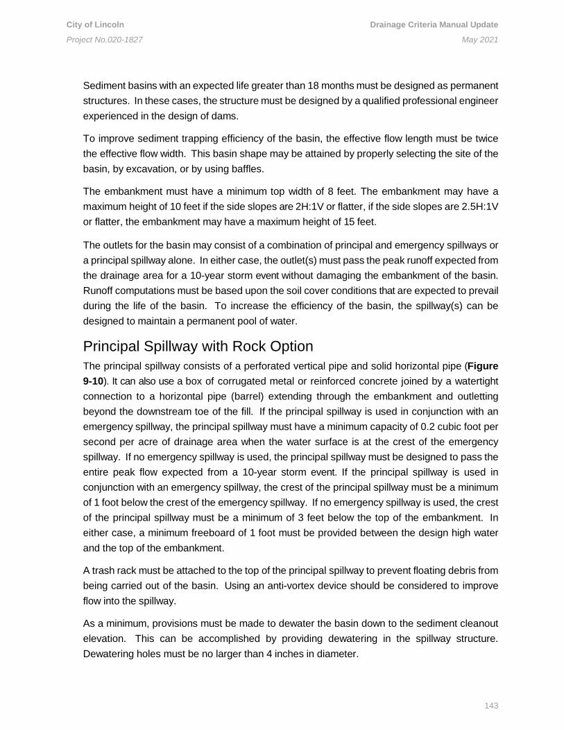
City of Lincoln Drainage Criteria Manual Update
Project No.020-1827 May 2021
143
Sediment basins with an expected life greater than 18 months must be designed as permanent
structures. In these cases, the structure must be designed by a qualified professional engineer
experienced in the design of dams.
To improve sediment trapping efficiency of the basin, the effective flow length must be twice
the effective flow width. This basin shape may be attained by properly selecting the site of the
basin, by excavation, or by using baffles.
The embankment must have a minimum top width of 8 feet. The embankment may have a
maximum height of 10 feet if the side slopes are 2H:1V or flatter, if the side slopes are 2.5H:1V
or flatter, the embankment may have a maximum height of 15 feet.
The outlets for the basin may consist of a combination of principal and emergency spillways or
a principal spillway alone. In either case, the outlet(s) must pass the peak runoff expected from
the drainage area for a 10-year storm event without damaging the embankment of the basin.
Runoff computations must be based upon the soil cover conditions that are expected to prevail
during the life of the basin. To increase the efficiency of the basin, the spillway(s) can be
designed to maintain a permanent pool of water.
Principal Spillway with Rock Option
The principal spillway consists of a perforated vertical pipe and solid horizontal pipe (Figure
9-10). It can also use a box of corrugated metal or reinforced concrete joined by a watertight
connection to a horizontal pipe (barrel) extending through the embankment and outletting
beyond the downstream toe of the fill. If the principal spillway is used in conjunction with an
emergency spillway, the principal spillway must have a minimum capacity of 0.2 cubic foot per
second per acre of drainage area when the water surface is at the crest of the emergency
spillway. If no emergency spillway is used, the principal spillway must be designed to pass the
entire peak flow expected from a 10-year storm event. If the principal spillway is used in
conjunction with an emergency spillway, the crest of the principal spillway must be a minimum
of 1 foot below the crest of the emergency spillway. If no emergency spillway is used, the crest
of the principal spillway must be a minimum of 3 feet below the top of the embankment. In
either case, a minimum freeboard of 1 foot must be provided between the design high water
and the top of the embankment.
A trash rack must be attached to the top of the principal spillway to prevent floating debris from
being carried out of the basin. Using an anti-vortex device should be considered to improve
flow into the spillway.
As a minimum, provisions must be made to dewater the basin down to the sediment cleanout
elevation. This can be accomplished by providing dewatering in the spillway structure.
Dewatering holes must be no larger than 4 inches in diameter.

City of Lincoln Drainage Criteria Manual Update
Project No.020-1827 May 2021
144
A stone filter will be required around the spillway structure to prevent loss of stored sediment.
A mesh-like material (e.g., chicken wire) should be installed around the perforated vertical
pipe to prevent rock from falling into it; filter cloth should not be used because it can cause
clogging issues. The base of the principal spillway must be firmly anchored to prevent it from
floating. If the riser of the spillway is greater than 10 feet in height, computations must be done
to determine the anchoring requirements. As a minimum, a safety factor of 1.25 must be used
(downward forces = 1.25 × upward forces).
Principal Spillway with Skimmer Option
This is similar to the Principal Spillway with Rock option, except that no rock is used and the
vertical pipe is not perforated. Instead, a skimmer is used and connected to the vertical pipe
near the bottom (see Figure 9-11).
The barrel of the principal spillway, which extends through the embankment, must be designed
to carry the flow provided by the riser of the principal spillway with the water level at the crest
of the emergency spillway. The connection between the riser and the barrel must be watertight
and he outlet of the barrel must be protected to prevent erosion or scour of downstream areas.
If the pond is not provided with a means for releasing the stored runoff between inflow storms,
anti-seep collars must be used on the barrel of the principal spillway within the normal
saturation zone of the embankment to increase the seepage length by at least 10 percent, if
either the settled height of the embankment exceeds 10 feet, or the embankment has a low silt-
clay content (Unified Soil Classes SM or GM). Anti-seep collars must be installed within the
saturated zone. The maximum spacing between collars must be 14 times the projection of the
collar above the barrel. Collars must not be closer than 2 feet to a pipe joint and should be
placed sufficiently far apart to allow space for hauling and compacting equipment. Connections
between the collars and the barrel must be watertight.
The emergency spillway must consist of an open channel constructed adjacent to the
embankment over undisturbed material (not fill). Figure 9-12 illustrates emergency spillways.
The emergency spillway must be designed to carry the peak rate of runoff expected from a 10-
year storm event, less any reduction, because of the flow through the principal spillway. The
design high water level through the emergency spillway must be at least 1 foot below the top
of the embankment. The crest of the emergency spillway channel must be at least 1 foot above
the crest of the principal spillway. The channel must be located to avoid sharp turns or bends
and must return the flow of water to a defined channel downstream from the embankment.
Maximum velocities: The maximum allowable velocity in the emergency spillway channel will
depend upon the type of lining used. See Chapter 5 of this manual for allowable velocities.

City of Lincoln Drainage Criteria Manual Update
Project No.020-1827 May 2021
145
Constructed sediment traps that are temporary must be removed after the contributing drainage
area is stabilized. Plans should show how the site of the temporary sediment trap is to be
graded and stabilized after removal of the sediment trap. Plans should show how the site of
the temporary sediment trap is to be graded and stabilized after removal. A geotechnical report
is required if the temporary sediment trap is to be used for a buildable lot. The permittee is
required to demonstrate, prior to the notice of termination approval, that the temporary
sediment trap is suitable for building structures on the property that the sediment basin
occupied.
Construction guidelines for temporary sediment basins are the following:
• Areas under the embankment and any structural works shall be cleared, grubbed,
and stripped of topsoil to remove trees, vegetation, roots, or other such material. To
facilitate cleanout and restoration, the pool area (measured at the top of the principal
spillway) will be cleared of all brush and trees.
• When a cutoff trench is specified, it shall be excavated along the centerline of the dam.
The minimum depth shall be 2 feet and the minimum bottom width shall be 4 feet, but
wide enough to permit operation of compaction equipment. The cutoff trench must
extend up both abutments to the riser crest elevation and the side slopes must be no
steeper than 1H:1V. Compaction requirements shall be the same as those for the
roadway embankment. The trench shall be drained during the backfilling-compacting
operations.
• When discharging drainage from basins and impoundments, the site must use outlet
structures that withdraw water from the surface, unless infeasible. The riser of the principal
spillway must be securely attached to the barrel by a watertight connection. The barrel
and riser must be placed on a firmly compacted soil foundation. The base of the riser
shall be firmly anchored according to design criteria to prevent it from floating. Pervious
materials such as sand, gravel, or crushed stone must not be used as backfill around
the barrel or anti-seep collars. Fill material must be placed around the pipe in 4-inch
layers and compacted by hand at least to the same density as the embankment. A
minimum of 2 feet of fill must be hand-compacted over the barrel before crossing it with
construction equipment.
• Design elevations, widths, and entrance and exit channel slopes are critical to the
successful operation of the emergency spillway and should be adhered to closely during
construction
• The fill material shall be taken from approved borrow areas. The fill material must be
clean mineral soil and be free of roots, woody vegetation, oversized stones, rocks, or
other such material. Areas on which fill is to be placed must be scarified prior to the
placement of fill. Fill material will be placed in 6- to 8-inch continuous layers over the
entire length of the fill. Compaction shall be obtained by routing the hauling equipment

City of Lincoln Drainage Criteria Manual Update
Project No.020-1827 May 2021
146
over the fill so that the entire surface of the fill is traversed by at least one wheel or tread
track of the equipment, or by using a compactor.
• The embankment and emergency spillway of the sediment basin must be stabilized with
temporary vegetation
• The construction of the sediment basin shall be carried out in a manner that does not
result in any undue sediment problems downstream
• All state and local requirements must be met concerning fencing and signs warning the
public of the hazards of soft sediment and floodwaters
9.3.14 Temporary Seeding
Temporary seeding is the establishment of a temporary vegetative cover on disturbed areas
by seeding with appropriate rapidly growing annual or perennial plants. The purpose of
temporary seeding is to reduce erosion and sedimentation by stabilizing disturbed areas that
will not be brought to final grade for a period of 30 days or more; to reduce damage from
sediment and runoff to downstream or off-site areas; and to provide protection to bare soils
exposed during construction until permanent vegetation or other erosion control measures can
be established. Temporary seeding is required when any clearing, grading, excavating, or
other earth-disturbing activities have permanently ceased on any portion of the site, or when
those activities have temporarily ceased on any portion of the site and will not resume for a
period exceeding 14 calendar days.
Temporary seeding should be used on exposed soil surfaces including denuded areas, soil
stockpiles, dikes, dams, sides of sediment basins, temporary road banks, etc. A permanent
vegetative cover must be applied to areas that will be left dormant for a period of more than
one year.
Construction guidelines for temporary seeding are the following:
• Prior to applying temporary seeding, install all necessary erosion control practices such
as dikes, waterways, and basins
• Provide proper shaping of the area to be seeded in such a manner that seedbed
preparation and seeding operations can be carried out
• When preparing a seedbed, if the area has been recently loosened or disturbed, no
further roughening is required. When the area is compacted, crusted, or hardened, the
soil surface shall be loosened by discing, raking, harrowing, or other acceptable means.
Seedbed preparation should not be undertaken when excessively wet conditions exist.
The seedbed shall be prepared to a depth of approximately 3 inches.
• If the soil being seeded is fertile topsoil, fertilizer is not required. However, if subsoil
is to be seeded, it will most likely be deficient in nutrients required for seed
germination and growth. A 10-20-20 fertilizer should be used (450 pounds/acre), and

City of Lincoln Drainage Criteria Manual Update
Project No.020-1827 May 2021
147
it is essential that this fertilizer be incorporated into the top 2 inches to 4 inches of
soil during seedbed preparation. Highly acidic soils should be limed.
o Certified seed must be used on all temporary seedings. Select plants
appropriate to the season and site conditions from those listed in Table 9-5.
Seed should be evenly applied with a drill, cultipacker seeder, or hydroseeder.
For cyclone spreaders, the rate should be twice that of drill seeding. Small
grains shall be planted no more than 1.5 inches deep and grasses no more
than one-half inch deep.
o When seedings are made on critical sites or adverse soil conditions, mulch
material will be applied immediately after seeding
o Seedings made during optimum seeding dates and with favorable soils on very
flat areas may not require mulch
o Maintenance factors for temporary seeding include reseeding areas that fail to
establish vegetative cover adequate to prevent rill erosion as soon as such
areas are identified. Weeds must be controlled by mowing.
9.3.15 Permanent Seeding
Permanent seeding results in vegetation that is established, perennial vegetative cover on
disturbed areas and is planted by seed. Its purpose is to reduce erosion and sediment yield
from disturbed areas; to permanently stabilize disturbed areas in a manner that is economical,
adaptable to site conditions, and allows selection of the most appropriate plant materials; to
improve wildlife habitat; and to enhance natural beauty. Permanent seeding that results in
permanent vegetation may be used on disturbed areas where permanent, long-lived vegetative
cover is needed to stabilize the soil and on rough-graded areas that will not be brought to final
grade for a year or more.
Construction guidelines for permanent seeding are:
• Prior to seeding, install all necessary erosion control practices such as dikes,
waterways, and basins
• Provide proper shaping of the area to be seeded so that seedbed preparation and
seeding operations can be carried out
• Soil conditions needed for the establishment and maintenance of permanent seeding
must include (1) enough fine-grained material to maintain adequate moisture and
nutrient supply; (2) sufficient pore space to permit root penetration; (3) a bulk density
of 1.2 to 1.5, indicating that sufficient pore space is present; (4) a fine granular or
crumb-like structure, which is favorable; (5) sufficient depth of soil to provide an
adequate root zone; (6) depth to rock or impermeable layers such as hardpans that
are 12 inches or more, except on slopes steeper that 2H:1V where the addition of soil

City of Lincoln Drainage Criteria Manual Update
Project No.020-1827 May 2021
148
is not feasible; (7) a favorable pH range for plant growth (if the soil is so acidic that a
pH range of 6.0 to 7.0 cannot be attained by addition of pH-modifying materials, then
the soil is considered an unsuitable environment for plant roots, and further soil
modification would be required); (8) freedom from toxic amounts of materials harmful
to plant growth; and (9) freedom from excessive quantities of roots, branches, large
stones, large clods of earth, or trash of any kind. Clods and stones may be left on
slopes steeper than 3H:1V if they do not significantly impede good seed-to-soil
contact. If any of the preceding criteria cannot be met, then topsoil must be applied.
• Seedbeds should be prepared in flat areas with slopes up to 3H:1V grade and shall be
loose and friable to a depth of at least 3 inches. The top layer of soil shall be loosened
by raking, discing, or other acceptable means before seeding. Slopes steeper than
3H:1V must have the top 1 inch to 3 inches of soil loose and friable before seeding.
When the area is compacted, crusted, or hardened, the soil surface shall be loosened
by discing, raking, harrowing, or by other acceptable means. Seedbed preparation
should not be undertaken when excessively wet conditions exist. Soil amendments
must be applied according to the recommendations of a soil test.
• Rolled erosion control products or hydro seeding should be used to help establish
vegetation on previously disturbed slopes of 3H:1V or steeper (see Sections 9.3.19
Rolled Erosion Control Products and 9.3.16 Hydroseeding/Hydromuchling).
Design a seed mix by using a City of Lincoln-approved seed mix. Seed mixtures for permanent
plantings will contain a mixture of two or more species, though a single species may be used
on some residential or recreational areas. Certified “blue tagged” seed will be used on all
permanent seedings.
Permanent seedings shall have a minimum of 90 PLS (Pounds of Live Seed) / acre. The seed
should be evenly applied in two directions with a cyclone spreader, drill, cultipacker seeder,
or hydroseeder on a firm, moist seedbed. When using a method of application other than a
hydroseeder, maximum seeding depth shall be one-quarter inch on clayey soils and one-half
inch on sandy soils. If hydroseeding is used and the seed and fertilizer are mixed, they will be
mixed on-site, and the seeding shall be immediate without interruption. See City of Lincoln
Standard Specifications, Chapter 30.04, for application periods.
A protective cover crop of annual plants may be seeded for erosion protection until
establishment of the permanent vegetation. Cover crop planting may be done in conjunction
with permanent seeding or immediately after permanent seeding has taken place. Select
cover crop plants appropriate to the season and site conditions from those listed in City of
Lincoln Standard Specifications, Chapter 30.06.

City of Lincoln Drainage Criteria Manual Update
Project No.020-1827 May 2021
149
All permanent seedings must be mulched immediately upon completion of seed application.
Maintenance factors for permanent seeding include the fact that in general, a stand of
vegetation cannot be determined to be fully established until it has been maintained for one full
year after planting. New seedings shall be supplied with adequate moisture; supply water as
needed, especially late in the spring season. Water applications shall be controlled to prevent
excessive runoff. Inspect all seeded areas for failures and make necessary repairs,
replacements, and reseedings within the planting season, if possible. If a stand is inadequate
for erosion control, over-seed and fertilize using half of the rates originally specified. Fertilizer
should be a low- or no-phosphorus mix. If the stand is 60 percent damaged, reestablish
following seedbed and seeding recommendations. If the stand has less than 40 percent cover,
reevaluate for use of soil amenities.
9.3.16 Hydroseeding / Hydromulching
Hydroseeding / hydromulching is a grass planting process. The process begins by mixing
mulch, seed, tackifier, fertilizer, and water into the tank of a hydromulching machine. The
material is often called a slurry. Once applied to the soil, the material enhances initial growth.
Figure 9-13 shows an installation detail for hydroseeding / hydromulching.
Many details should be included when designing a hydroseeding / hydromulching grass
planting process. Prior to hydromulching and hydroseeding, install any needed erosion and
sediment control practices. Complete required shaping of the area in such a manner that the
operations can be carried out. Seed must be incorporated as needed except where seed is to
be applied as part of the process.
Maintenance factors for hydroseeding / hydromulching include inspecting all mulches and soil
covering periodically and after each rain event to check for erosion. Where erosion is observed
in mulched areas, additional mulch should be applied.
9.3.17 Slope Tracking
Slope tracking is the technique used for surface roughening or scarification by means of
mechanical equipment. Slope tracking creates grooves that are perpendicular to the slope. The
primary functions for slope tracking are to reduce erosion potential by decreasing runoff
velocities, trap sediment, increase the chances for water infiltration, and aid in the
establishment of vegetative cover. Figure 9-14 shows an installation detail for slope tracking.
Many details should be included when designing slope tracking. When slope tracking is used
for a surface roughing technique, it shall be done by operating tracked machinery up and down
the slope to leave horizontal depressions in the soil. As few passes of the machinery as possible
should be made to minimize compaction. If the slope steepness is greater than 3H:1V, slope

City of Lincoln Drainage Criteria Manual Update
Project No.020-1827 May 2021
150
tracking is not recommended. Immediately seed and mulch roughened areas to obtain
optimum seed germination and growth.
Maintenance factors for slope tracking include inspecting areas after each storm event,
particularly after events that are greater than 0.05 inch. Regular inspections of slopes will
indicate where additional erosion and sediment controls are needed. If rills appear, they should
be filled, graded again, and reseeded immediately.
9.3.18 Mulching
Mulching is the application of plant residues or other suitable materials to the soil surface. The
purpose of mulching is to prevent erosion by protecting the soil surface from raindrop impact
and reducing the velocity of overland flow. Mulch helps foster the growth of vegetation by
increasing available moisture and providing insulation against extreme heat and cold; it can be
used at any time when protection of the soil surface is desired. Mulch can be used in
conjunction with seedings to establish vegetation, or it can be used by itself to provide
temporary protection of the soil surface.
Construction Guidelines for mulching are:
• To prepare the site prior to mulching, install any needed erosion and sediment control
measures such as diversions, grade stabilization structures, berms, dikes, grassed
waterways, and sediment basins. Complete required shaping of the area so that
mulching operations can be carried out. Soil amendments shall be incorporated, and
surface roughening accomplished as needed. Seed must be applied prior to mulching
except where seed is to be applied as part of a hydroseeding slurry containing fiber
mulch or where seed is to be applied following an organic mulch spread during winter
months.
• Organic materials may be used in any area where mulch is required. Select mulch
material based on site requirements, availability of materials, and availability of labor
and equipment (see City of Lincoln Standard Specifications, Chapter 30.04). Mulch
materials must be spread uniformly by hand or machine. When spreading straw mulch
by hand, divide the area to be mulched into approximately 1,000-square-foot sections
and place 70 to 90 pounds (two bales) of straw in each section to facilitate uniform
distribution.
• Anchor mulch immediately to minimize loss by wind and water. Anchoring may be
done by one of the following methods (listed by preference) depending upon the size
of area, erosion hazard, and cost.
• A mulch anchoring tool and tracking may be used to anchor mulch. A mulch anchoring
tool is a tractor-drawn implement designed to pinch and anchor mulch into the top 2
inches of soil. Use of a mulch anchoring tool offers maximum erosion control but is

City of Lincoln Drainage Criteria Manual Update
Project No.020-1827 May 2021
151
limited to flatter slopes where equipment can operate safely. The practice of tracking
should be done on the contour wherever possible, except when tracking is done up
and down the slope purposefully such that the cleat marks run perpendicular to the
slope. Tracking is used primarily on slopes 3H:1V or steeper.
Mulch nettings may be used to anchor mulch. Staple lightweight biodegradable paper, plastic,
or cotton netting over the mulch according to manufacturer’s recommendations.
Liquid mulch binders may be used to anchor mulch. Application of liquid mulch binders and
tackifiers should be heavier at edges of the project area, in valleys, and at crests of banks and
other areas where the mulch has a greater potential to be moved by wind or water. All other
areas should have a uniform application of binder. Binders may be applied after the mulch is
spread or may be sprayed into the mulch as it is being blown onto the soil. The use of synthetic
binders is the preferred method of mulch binding. Apply at rates recommended by the
manufacturer.
Wood cellulose fiber may be used to anchor mulch. The fiber binder shall be applied at a net
dry weight of 750 pounds/acre. The wood cellulose fiber shall be mixed with water, and the
mixture must contain a maximum of 50 pounds of wood cellulose fiber per 100 gallons of
water.
Peg and twine may be used to anchor mulch. Drive 8-inch to 10-inch wooden pegs to within
2 inches to 3 inches into the soil surface at intervals of 4 feet in all directions. Stakes may be
driven before or after applying mulch. Secure mulch to the soil surface by stretching twine
between pegs in a crisscross within a square pattern. Secure twine around each peg.
Maintenance factors for mulch include inspecting all mulches and soil coverings periodically
and after each rainstorm to check for erosion. Where erosion is observed in mulched areas,
additional mulch should be applied. Nets and mats should be inspected after rainstorms for
dislocation or failure. If washouts or breakage occur, reinstall netting or matting as
necessary after repairing damage to the slope or ditch. Inspections should take place until
grasses are firmly established. Where mulch is used in conjunction with ornamental
plantings, inspect periodically throughout the year to determine whether mulch is
maintaining coverage of the soil surface; repair as needed.
9.3.19 Rolled Erosion Control Products
Rolled erosion control products are protective covering netting, blankets, or turf reinforcement
mats (TRMs) installed on a prepared planning area of a steep slope, channel, or shoreline.
Rolled erosion control products aid in controlling erosion on critical areas by absorbing the
energy from raindrop impacts and by providing a microclimate that protects young vegetation
and promotes its establishment. TRMs are also used to raise the maximum permissible velocity

City of Lincoln Drainage Criteria Manual Update
Project No.020-1827 May 2021
152
and shear stress of turf grass stands in channelized areas by enabling the turf to resist the
forces of erosion during storm events. See Lincoln Standard Plan 179 for illustrations of rolled
erosion control products.
Design Details and Construction Guidelines:
• Netting, blankets, and TRMs will aid in controlling erosion on slopes steeper than 8
percent and of highly erodible soils by providing a protective cover made of straw, jute,
wood, or other organic plant fiber with cotton string or polypropylene netting to hold the
product flat
• Netting can be used alone over blown straw as an alternative to either using crimping
or using a tackifier
• These products can be used on short, steep slopes where erosion hazard is high, and
planting is likely to be too slow in providing adequate protective cover; in vegetated
channels where the design velocity and shear stress of design flow exceed allowable
rates on streambanks where moving water is likely to wash out new plantings; or in
areas where the forces of wind prevent standard mulching practices from remaining in
place until vegetation becomes established
• Before installation of these products, the area should be final graded to a smooth and
uniform surface, free of debris
• Topsoil should be incorporated if needed. Seed and fertilize as shown on the plan.
• The erosion control netting, blankets, and mats should be installed in accordance with
the manufacturer’s recommendations and specifications
• All products should be anchored following the manufacturer’s recommended stapling
pattern for each specific application
• Some important factors in the choice of netting, blanket, or TRM include soil conditions,
steepness of slope, length of slope, type, and duration of protection required to
establish desired vegetation, and probable sheer stress
• Consult the manufacturer’s product specifications to determine the correct product for
each specific application required
• A site visit by a designer or plan reviewer is highly recommended to verify a
product’s appropriateness
• Erosion control blankets should be used to help establish vegetation on previously
disturbed slopes of 3H:1V or steeper
• Since erosion control blankets are composed of materials that deteriorate over time,
they should be used in permanent conveyance channels with the realization that
resistance to erosion will ultimately be based on the type of vegetation planted and the
existing soil characteristics

City of Lincoln Drainage Criteria Manual Update
Project No.020-1827 May 2021
153
• During the establishment of vegetation, blankets should not be subjected to velocities
greater than 4 feet per second
• Erosion control blankets provide the following benefits when properly applied:
o Protection of the seed and soil from raindrop impact and subsequent
displacement
o Thermal consistency and moisture retention for seedbed area
o Stronger and faster germination of grasses and legumes
o Shedding off excess stormwater runoff
o Prevention of sloughing of topsoil added to steeper slopes
• TRMs consist of a nondegradable, three-dimensional polypropylene structure, which
may also have coconut or other organic fiber layers within it so long as the
nondegradable portion of the blanket will withstand design velocities and shear
stresses after the organic fibers degrade
• The matting becomes entangled and penetrated by roots forming continuous
anchorage for surface growth and promoting enhanced energy dissipation
• TRM’s should be used on slopes 2H:1V or steeper, and in stormwater conveyance
channels
• In addition to those benefits noted for blankets, TRMs provide the following benefits for
vegetative stabilization and when replacing concrete and riprap channel linings:
o Cause sediment to drop out of stormwater and fill matrix with fine soils, which
become the growth medium for the development of roots
o Act with the vegetative root system to form an erosion-resistant cover, which
resists hydraulic lift and shear forces when embedded in the soil within
stormwater channels
• Since TRMs are nondegradable, they can be used in permanent conveyance channels
to withstand higher velocities and shear stresses than would normally be allowable with
only soil and vegetation
• Permissible velocities and shear stresses for TRM for reinforced grass-lined channels
range from 10 to 20 feet per second and 6 pounds to 10 pounds per square foot,
respectively
9.3.20 Safety Fence
Safety fences are protective barriers installed to help prevent the public from using or
disturbing an erosion prevention measure. They may be applied to any control measure or
series of measures that can be considered unsafe or may be damaged by the public.
Many details should be included when designing safety fences. They should be located to
create a formidable barrier against undesired access while allowing for the continuation of

City of Lincoln Drainage Criteria Manual Update
Project No.020-1827 May 2021
154
necessary construction operations. Safety fences are most applicable to the construction of
berms, traps, and dams. When used with those structures, safety fences should be located
far enough beyond the outer toe of the embankment to allow for the passage of maintenance
vehicles. Fences should not be installed across the slope of a dam or dike. The height of the
fence shall be a minimum of 5 feet for plastic fence and 6 feet for metal fence; a fence must
never be so short as to become an attraction for children to climb on or over. Signs noting
potential hazards (such as “HAZARDOUS AREA – KEEP OUT”) should be posted so they
can be easily seen by anyone approaching the protected area. Plastic fence may be used as
safety fencing primarily in situations where the need is for a temporary barrier. The color of
safety fences shall be International Orange. Metal fencing should be used when a potentially
dangerous control measure will remain permanently, such as a stormwater detention basin;
however, metal fencing may also be used for measures that only serve a temporary function,
at the discretion of those responsible for project safety. Safety fences must be installed before
the erosion and sediment control measures become accessible.
Construction guidelines for safety fences are:
• The web of the plastic fence shall be secured to a conventional metal “T” or “U” post
driven into the ground to a minimum depth of 18 inches. Posts should be spaced on
6-foot centers.
• Applicable warning signs noting hazardous conditions must be installed immediately
upon installation of safety fence
Maintenance factors for safety fences include checking them regularly for weather-related or
other damage; any necessary repairs must be made immediately. Care should be taken to
secure all access points at the end of each working day. All locking devices must be repaired
or replaced, as necessary.
9.3.21 Dust Control
Dust control is the practice of reducing surface and air movement of dust during land-
disturbing, demolition, and construction activities. The purpose of dust control is to prevent
surface and air movement of dust from exposed soil surfaces and to reduce the presence of
airborne substances that may present health hazards or traffic safety problems or may harm
animal or plant life. Dust control measures should be taken in areas subject to surface and air
movement of dust where on‐site and off‐site damage is likely to occur if preventative measures
are not taken.
Many details should be included when designing dust control measures. In areas subject to
little or no construction traffic, a vegetative stabilized surface will reduce dust emissions.
Mulch, properly applied, offers a fast, effective means of controlling dust. Mulch is not
recommended for areas within heavy traffic pathways. Binders or tackifiers should be used to

City of Lincoln Drainage Criteria Manual Update
Project No.020-1827 May 2021
155
tack organic mulches.
Tillage is designed to make the surface rougher and bring clods to the surface to reduce wind
erosion to the soils. This emergency measure should be used before wind erosion starts.
Begin plowing on the windward side of the site. Chisel‐type plows spaced about 12 inches
apart, spring‐toothed harrows, and similar plows are examples of equipment that may produce
the desired effect.
Irrigation is the most commonly used dust control practice. The site is sprinkled with water
until the surface is wet; repeat as needed. Irrigation offers fast protection for haul roads and
other heavy-traffic areas. Spray‐on adhesives can be used on “mineral” soils; it is not effective
on “muck” soils. Traffic should be kept off treated areas.
Aggregate can be used to stabilize roads or other areas during construction. A board fence,
wind fence, sediment fence, or other, similar barrier can help control air currents and blowing
soil. Place barriers perpendicular to prevailing air currents at intervals of about 15 times the
barrier height. Where dust is a known problem, existing windbreak vegetation should be
preserved.
Calcium chloride may be applied by a mechanical spreader as loose, dry granules or flakes
at a rate that keeps the surface moist but not does not cause water pollution or plant damage.
Application rates should be strictly in accordance with supplier’s specified rates. Applying
permanent seeding and saving existing trees and large shrubs can help reduce soil and air
movement from construction sites.
To control dust from saw-cutting operations, there are two methods: wet dust suppression and
local exhaust ventilation (LEV). Wet dust suppression involves spraying water onto the cutting
disk to reduce dust emissions and should not be used for electrically operated saws.
Application flow rates are determined by the manufacturer of the equipment utilized. The LEV
method can be used for all hand‐held saws. The LEV method uses a dust-collecting hood
connected to a vacuum cleaner to capture dust; this system does not produce a wet slurry.
To prevent the recirculation of dust, vacuums should be fitted with a HEPA filtered vacuum
filter.
Refer to the Occupational Safety and Health Administration (OSHA) Small Entity Compliance
Guide for standards and recommendations (OSHA 2019). Additional information regarding Air
and Water prohibitions can be found under the Lincoln Municipal Code(s) (LMC) 8.06.150 and
28.02.050.

City of Lincoln Drainage Criteria Manual Update
Project No.020-1827 May 2021
156
9.3.22 Other Best Management Practices
For brevity, the following listed structural control measures are not discussed herein, but they
may be useful in specialized applications. If any of these structural control measures are used
for sediment and erosion control purposes, permittee must have Director’s approval. Other
BMP practices are listed below:
• Brush barrier
• Temporary slope drain
• Road stabilization
• Utility stream crossing (e.g., diversion channel crossing, flume pipe crossing, coffer
dam crossing)
• Dewatering structure (e.g., portable sediment tank, filter box, straw bale/silt fence pit)
• Temporary fill diversion
• Turbidity curtain
• Surface roughening
• Lot benching
• Paved flumes
• Subsurface drain
• Structural streambank stabilization (e.g., gabions, deflectors, log cribbing, grid pavers)
• Grade stabilization structure
• Infiltration basin
• Infiltration trench
• Stormwater conveyance channel
• Vegetative stream bank stabilization
• Topsoiling
• Permanent diversion
• Vegetated swale
• Temporary right-of-way diversion
• Other industry accepted practices

City of Lincoln Drainage Criteria Manual Update
Project No.020-1827 May 2021
157
Figure 9-1. Process Chart.

City of Lincoln Drainage Criteria Manual Update
Project No.020-1827 January 2021
158
Figure 9-2. Vegetated Filter / Buffer Strip.

City of Lincoln Drainage Criteria Manual Update
Project No.020-1827 January 2021
159
Table 9-1. Typical Land Slope and Distance for Silt Fence.
Land Slope (%) Maximum Slope Distance* Above Fence (feet)
Less than 2 150
2 to 5 100
*Follow manufacturer’s recommendations for proper placing.

City of Lincoln Drainage Criteria Manual Update
Project No.020-1827 January 2021
160
Figure 9-3. Wattle Barrier Installation.

City of Lincoln Drainage Criteria Manual Update
Project No.020-1827 January 2021
161
Figure 9-4. Compost Berm Detail.

City of Lincoln Drainage Criteria Manual Update
Project No.020-1827 May 2021
162
Table 9-2. Permissible Velocities for Grass- and Earth-lined Channels.
Grass-lined Channels:
Channel Slope (%) Cover Permissible Velocity (ft/sec)
0.5 Bermuda grass
Reed canary grass
Tall fescue
Kentucky bluegrass
Grass legume mixture
Red fescue
Redtop
Sericea lespedeza
Annual lespedeza
6
5
5
5
4
4
4
4
4
0.5 to 1 Bermuda grass
Reed canary grass
Tall fescue
Kentucky bluegrass
Grass legume mixture
5
4
4
4
3
Greater than 1 Bermuda grass
Reed canary grass
Tall fescue
Kentucky bluegrass
4
3
3
3
Earth-lined Channels:
Soil Types Permissible Velocity (ft/sec)*
Fine Sand (noncolloidal) 2.5
Sandy Loam (noncolloidal) 2.5
Silt Loam (noncolloidal) 3.0
Ordinary Firm Loam 3.5
Fine Gravel 5.0
Stiff Clay (very colloidal) 5.0
Graded, Loam to Cobbles (noncolloidal) 5.0
Graded, Silt to Cobbles (colloidal) 5.5
Alluvial Silts (noncolloidal) 3.5
Alluvial Silts (colloidal) 5.0
Coarse Gravel (noncolloidal) 6.0
Cobbles and Shingles 5.5
Shales and Hard Pans 6.0
* For highly erodible soils, decrease permissible velocities by 25 percent.

City of Lincoln Drainage Criteria Manual Update
Project No.020-1827 May 2021
163
Figure 9-5. Temporary Diversion Dike.

City of Lincoln Drainage Criteria Manual Update
Project No.020-1827 May 2021
164
Figure 9-6. Rock Check Dams.

City of Lincoln Drainage Criteria Manual Update
Project No.020-1827 May 2021
165
Table 9-3. Properties of Filter Cloth.
Fabric Properties (1) Light Duty
Entrance (2)
Heavy Duty
Entrance (3) Test Method
Grab Tensile Strength (lbs) 180 250 ASTM D4632
Elongation at Failure (%) 50 60 ASTM D4632
Mullen Burst Strength (psi) 250 380 ASTM D3786
Puncture Strength (lbs) 90 125 ASTM D4833
Apparent Opening Size (mm) 0.20 0.20 ASTM D4751
Aggregate Depth (inches) 6 10 ASTM D4751
(1) Fabrics not meeting these specifications may be used only when design procedure and supporting
documentation are supplied to determine aggregate depth and fabric strength.
(2) Light duty entrance shall be defined as sites that have been graded to subgrade and where most travel
would be by single-axle vehicles and an occasional multi-axle truck. Examples of fabrics that can be
used are Trevira Spunbond 1125, Synthetic Industries 701, Polyfelt TS650, or equivalent.
(3) Heavy duty entrance shall be defined as sites with only rough grading and where most travel would
be by multi-axle vehicles. Examples of fabrics that can be used are Trevira Spunbond 1135, Synthetic
Industries 1001, Polyfelt TS750, or equivalent.

City of Lincoln Drainage Criteria Manual Update
Project No.020-1827 May 2021
166
Figure 9-7. Temporary Culvert Crossing.

City of Lincoln Drainage Criteria Manual Update
Project No.020-1827 May 2021
167
Table 9-4. General Guideline Pipe Diameter (inches) for Stream Crossings.*
Drainage Area Acres Average Slope of Watershed
1% 4% 8% 16%
1 – 25 24 24 30 30
16 – 50 24 30 36 36
51 – 100 30 36 42 48
101 – 150 30 42 48 48
151 – 200 36 42 48 54
201 – 250 42 48 54 60
251 – 300 42 48 54 60
301 – 350 42 48 60 60
351 – 400 42 54 60 60
401 – 450 42 54 60 72
451 – 500 42 54 60 72
501 – 550 48 60 60 72
551 – 600 48 60 60 72
Greater than 600 Detailed calculations required
*Note: Table generally based 2-year frequency storm event with curve number = 65, rainfall depth 3.5
inches.
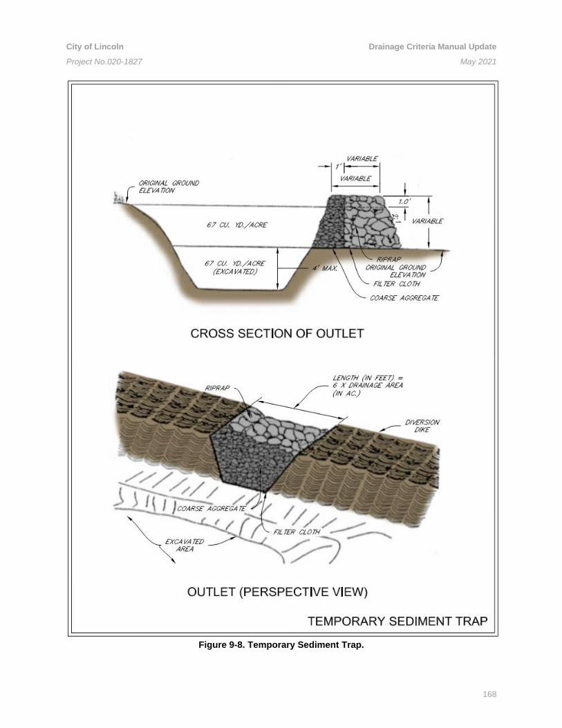
City of Lincoln Drainage Criteria Manual Update
Project No.020-1827 May 2021
168
Figure 9-8. Temporary Sediment Trap.

City of Lincoln Drainage Criteria Manual Update
Project No.020-1827 May 2021
169
Figure 9-9. Sediment Trap Embankment Diagram.

City of Lincoln Drainage Criteria Manual Update
Project No.020-1827 May 2021
170
Figure 9-10. Principal Spillway with Rock Option.

City of Lincoln Drainage Criteria Manual Update
Project No.020-1827 May 2021
171
Figure 9-11. Principal Spillway with Skimmer Option.

City of Lincoln Drainage Criteria Manual Update
Project No.020-1827 May 2021
172
Figure 9-12. Emergency Spillway.

City of Lincoln Drainage Criteria Manual Update
Project No.020-1827 May 2021
173
Table 9-5. Guidelines for Temporary Seeding.
Time of Year Species Seeding Rate
March 15 – May 15 Spring Oats
Barley
Perennial Ryegrass
Orchard Grass
2 bushels/acre
2 bushels/acre
30-40 lbs/acre
20-25 lbs/acre
May 16 – July 15 Grain Sorghum (drilled)
Forage Sorghum (drilled)
Hybrid Sundangrass
10-20 lbs/acre
10-20 lbs/acre
20-30 lbs/acre
July 16 – October 15 Spring Oats
Barley
2 bushels/acre
2 bushels/acre
August 16 – October 15 Winter Wheat
Winter Rye
1.5 bushels/acre
1.5 bushels/acre
October 15 – Mar 15 No planting, use mulches

City of Lincoln Drainage Criteria Manual Update
Project No.020-1827 May 2021
174
Figure 9-13. Hydroseed / Hydromulch / Polymer Application.

City of Lincoln Drainage Criteria Manual Update
Project No.020-1827 May 2021
175
Figure 9-14. Slope Tracking / Contour Furrows.