Technical Report – Task 2.2 Definition of Overall System Architecture

CALIFORNIA
ENERGY COMMISSION
PIER Lighting Research ProgramProject 2.2 LED Task Light Utilizing New Materials to
Reduce Thermal Stress on High Brightness LEDs
FINAL REPORT
Con
sulta
nt R
epor
t
January 2005 500-01-041-A-3
Arnold Schwarzenegger, Governor

CALIFORNIA
ENERGY
COMMISSION
Prepared By: Lawrence Berkeley National
Laboratory
Steve Johnson, Project Lead Berkeley, CA Managed By: Architectural Energy Corporation Judie Porter Program Director Boulder, CO CEC Contract # 500-01-041 Prepared For: Don Aumann Contract Manager Nancy Jenkins PIER Buildings Program Manager DISCLAIMER This report was prepared as the result of work sponsored by the
California Energy Commission. It does not necessarily represent the views of the Energy Commission, its employees or the State of California. The Energy Commission, the State of California, its employees, contractors and subcontractors make no warrant, express or implied, and assume no legal liability for the information in this report; nor does any party represent that the uses of this information will not infringe upon privately owned rights. This report has not been approved or disapproved by the California Energy Commission nor has the California Energy Commission passed upon the accuracy or adequacy of the information in this report.

LED Task Lighting LBNL/Architectural Energy Corporation
PIER Lighting Research Program 3 500-01-041
Contact Information: Subcontract Project Manager Steve Johnson Lawrence Berkeley National Laboratory 1 Cyclotron Rd., Building 90R3111 Berkeley, CA 94720 510 486-4096 – Voice 510 486-4089 – FAX [email protected]
AEC Program Director Judie Porter Architectural Energy Corporation 2540 Frontier Avenue Boulder, CO 80301 303-444-4149 – Voice 303-444-4304 - Fax [email protected]
Prepared By: Steve Johnson, Lawrence Berkeley National Laboratory Project Team Steve Johnson, Lawrence Berkeley National Laboratory (LBNL) Akos Borbely, LBNL Neil Fromer, LBNL Tal Margalith, LBNL Jim Galvin, LBNL Sam Gromins, Luxo Manuel Lynch, Permlight James Ibbetson, Cree Julio Vera, Advance Transformer Included in the Team…. Erlend Lillelien, Luxo, Oslo, Norway This work was completed under contract to Lawrence Berkeley National Laboratory as part of the California Energy Commission's Lighting Research Program. This program is supported by the California Energy Commission's Public Interest Energy Research (PIER) Buildings Program and the Assistant Secretary for Energy Efficiency and Renewable Energy, Office of Building Technology, Building Technologies Program, of the U.S. Department of Energy under Contract No. DE-AC03-76SF00098.

LED Task Lighting LBNL/Architectural Energy Corporation
PIER Lighting Research Program 4 500-01-041
Acknowledgements Lawrence Berkeley National Laboratory (LBNL) would like to acknowledge the contribution of Erlend Lillelien, Luxo (Norway), throughout the development program and the supply of luminaires given by Luxo in support of this program. LBNL would also like to acknowledge the contribution of James Ibbetson, Cree, for his technical support throughout the program and the contribution of materials by Cree prior to their market availability. LBNL also acknowledges the support of Permlight and Advance in supplying materials that significantly advanced the development of the prototypes assembled in this project. LBNL greatly appreciates and wishes to acknowledge the invaluable assistance of the following individuals: Element 2 Technical Advisory Group: Al Marble, Advance Transformer; James Ibbetson, Cree Lighting; Ted Ferreira, City Design Group; Bill Daiber, WFD Associates. Program Advisory Committee: Ron Lewis, Department of Energy; Jerry Mills, Easy Lite; Gregg Ander, SCE; Bill Daiber, WFD Associates; James Bryan, Arden Realty; Neall Digert, Solatube; Jim Benya, Benya Lighting; Dennis Tiede, Sempra Utilities; Noah Horowitz, NRDC; Amy Cortese, Northwest Energy Efficiency Alliance; Pekka Hakkarainen, Lutron; Peter Turnbull, PG&E; Michael Waxer, Carmel Development Co; Kit Tuveson, Tuveson & Associates; David Kaneda, Integrated Design Associates, Inc; Connie Buchan, SMUD. Program and Contract Management: Eric Stubee and Nancy Jenkins, California Energy Commission; Karl Johnson, CIEE; Judie Porter, Architectural Energy Corporation; Don Aumann, CLTC.

LED Task Lighting LBNL/Architectural Energy Corporation
PIER Lighting Research Program 5 500-01-041
Table of Contents Acknowledgements ................................................................................................................4 Preface....................................................................................................................................8 Executive Summary ...............................................................................................................9
Introduction........................................................................................................................9 Project Objectives ..............................................................................................................9 Project Outcomes .............................................................................................................10 Recommendations............................................................................................................11 Conclusions......................................................................................................................12 Benefits to California .......................................................................................................12
Abstract ................................................................................................................................13 Introduction..........................................................................................................................14
Background and Overview...............................................................................................14 Project Objectives ............................................................................................................14
Project Approach..................................................................................................................16 Project Tasks ....................................................................................................................16
Project Outcomes .................................................................................................................17 Summary of Project Outcomes ........................................................................................17 Development of Thermal Transport Subsystem ..............................................................18 First Prototype Task Light ...............................................................................................23 Second Prototype Task Light ...........................................................................................30
Conclusions and Recommendations ....................................................................................45 Recommendations............................................................................................................45 Commercialization Potential............................................................................................45 Benefits to California .......................................................................................................46 Conclusions......................................................................................................................46
LED Task Lighting LBNL/Architectural Energy Corporation
PIER Lighting Research Program 6 500-01-041
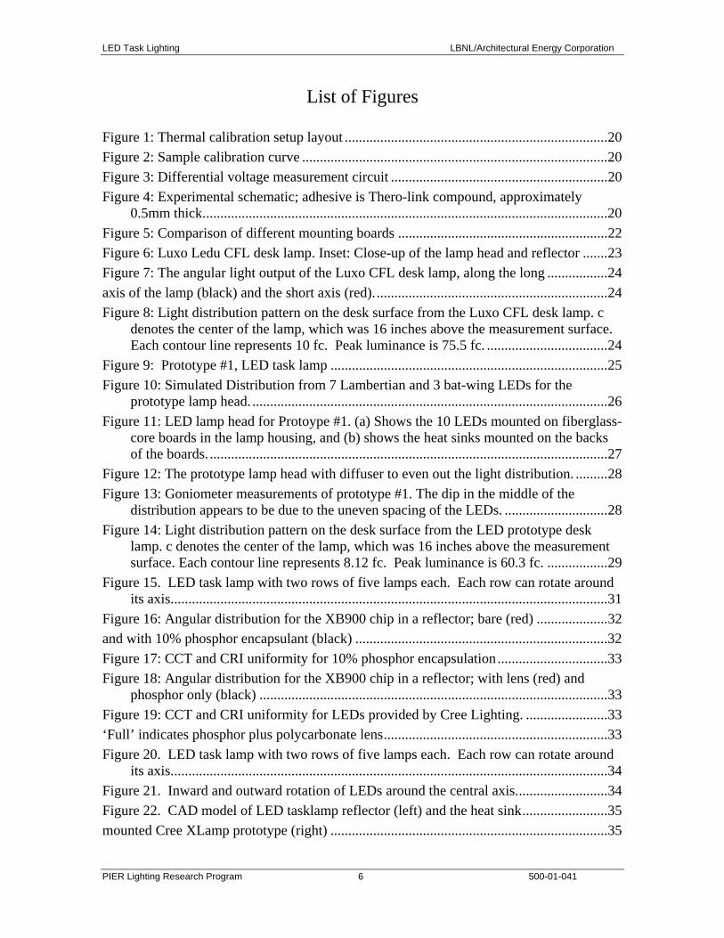
List of Figures Figure 1: Thermal calibration setup layout ..........................................................................20 Figure 2: Sample calibration curve ......................................................................................20 Figure 3: Differential voltage measurement circuit .............................................................20 Figure 4: Experimental schematic; adhesive is Thero-link compound, approximately
0.5mm thick..................................................................................................................20 Figure 5: Comparison of different mounting boards ...........................................................22 Figure 6: Luxo Ledu CFL desk lamp. Inset: Close-up of the lamp head and reflector .......23 Figure 7: The angular light output of the Luxo CFL desk lamp, along the long .................24 axis of the lamp (black) and the short axis (red)..................................................................24 Figure 8: Light distribution pattern on the desk surface from the Luxo CFL desk lamp. c
denotes the center of the lamp, which was 16 inches above the measurement surface. Each contour line represents 10 fc. Peak luminance is 75.5 fc. ..................................24
Figure 9: Prototype #1, LED task lamp ..............................................................................25 Figure 10: Simulated Distribution from 7 Lambertian and 3 bat-wing LEDs for the
prototype lamp head. ....................................................................................................26 Figure 11: LED lamp head for Protoype #1. (a) Shows the 10 LEDs mounted on fiberglass-
core boards in the lamp housing, and (b) shows the heat sinks mounted on the backs of the boards. ................................................................................................................27
Figure 12: The prototype lamp head with diffuser to even out the light distribution. .........28 Figure 13: Goniometer measurements of prototype #1. The dip in the middle of the
distribution appears to be due to the uneven spacing of the LEDs. .............................28 Figure 14: Light distribution pattern on the desk surface from the LED prototype desk
lamp. c denotes the center of the lamp, which was 16 inches above the measurement surface. Each contour line represents 8.12 fc. Peak luminance is 60.3 fc. .................29
Figure 15. LED task lamp with two rows of five lamps each. Each row can rotate around its axis...........................................................................................................................31
Figure 16: Angular distribution for the XB900 chip in a reflector; bare (red) ....................32 and with 10% phosphor encapsulant (black) .......................................................................32 Figure 17: CCT and CRI uniformity for 10% phosphor encapsulation...............................33 Figure 18: Angular distribution for the XB900 chip in a reflector; with lens (red) and
phosphor only (black) ..................................................................................................33 Figure 19: CCT and CRI uniformity for LEDs provided by Cree Lighting. .......................33 ‘Full’ indicates phosphor plus polycarbonate lens...............................................................33 Figure 20. LED task lamp with two rows of five lamps each. Each row can rotate around
its axis...........................................................................................................................34 Figure 21. Inward and outward rotation of LEDs around the central axis..........................34 Figure 22. CAD model of LED tasklamp reflector (left) and the heat sink........................35 mounted Cree XLamp prototype (right) ..............................................................................35

LED Task Lighting LBNL/Architectural Energy Corporation
PIER Lighting Research Program 7 500-01-041
Figure 23. SLA prototype reflector with specular metal coating........................................36 Figure 24. SLA prototype reflector with diffuse white paint coating. ................................36 Figure 25. Specular Reflector: simulated and measured spatial output ..............................37 Figure 26. Comparison of the distribution of the diffuse white coating to the specular
reflective coating..........................................................................................................38 Figure 27. Simulated output showing how turning the reflector rows inward increases
illuminance levels.........................................................................................................39 Figure 28. Simulated output showing illuminance levels when the sources are normal to
the illuminated surface. ................................................................................................39 Figure 29. Simulated output showing how rotation of the reflector rows outward allows a
larger area to be illuminated.........................................................................................39 Figure 30. Spatial distribution of LED subsystem. .............................................................39 Figure 31. Alternative designs for the LED cooling structure ............................................42 Figure 32. Various comparisons photos of the CFL versus the LED prototype. ................44

LED Task Lighting LBNL/Architectural Energy Corporation
PIER Lighting Research Program 8 500-01-041
Preface The Public Interest Energy Research (PIER) Program supports public interest energy research and development that will help improve the quality of life in California by bringing environmentally safe, affordable, and reliable energy services and products to the marketplace. The PIER Program, managed by the California Energy Commission, annually awards up to $62 million to conduct the most promising public interest energy research by partnering with Research, Development, and Demonstration (RD&D) organizations, including individuals, businesses, utilities, and public or private research institutions. PIER funding efforts are focused on the following six RD&D program areas:
• Buildings End-Use Energy Efficiency • Industrial/Agricultural/Water End-Use Energy Efficiency
• Renewable Energy
• Environmentally-Preferred Advanced Generation
• Energy-Related Environmental Research
• Strategic Energy Research
What follows is the final report for the PIER Lighting Research Program, Contract #500-01-041, Project 2.2 conducted by Lawrence Berkeley National Laboratory. The report is entitled Task Light Utilizing New Materials to Reduce Thermal Stress on High Brightness LEDs. This project contributes to the PIER Lighting Research Program. For more information on the PIER Program, please visit the Commission’s web site at http://www.energy.ca.gov/research/index.html or contact the Commission’s Publications Unit at (916) 654-5200.

LED Task Lighting LBNL/Architectural Energy Corporation
PIER Lighting Research Program 9 500-01-041
Executive Summary Introduction This project describes the results of LBNL’s research effort to develop an LED-based task light suitable for the general illumination market. LBNL has been performing basic and applied research in the development of LEDs, phosphors for LEDs, subassemblies and respective light sources and luminaires over the last four years. This project builds on experience developed in these previous efforts. Key findings and directions from this prior research include:
• The application to task lighting offers an immediate opportunity of introducing solid state light sources, and providing end-user benefits in energy efficiency and optical properties not achievable with current sources.
• The relationship of LED device performance to the thermal characteristics of the device is crucial. The LED performance can be increased through improved thermal management of the die temperatures.
• Further improvements in LED performance can be achieved with improved die processing, phosphors, and micro-optics.
Market penetration of an LED-based task light into the general illumination market does not exist. A luminaire using this technology would represent the current state-of-the-art task light. In addition, the technological improvements in thermal management and LED device performance demonstrated in this project will have application to virtually all future LED luminaires. Project Objectives The goal of this project is to accelerate the use of energy efficient light emitting diode (LED) technology for general lighting applications by developing a task lamp utilizing high brightness LEDs in a consumer acceptable light fixture, and utilizing new materials that have high thermal conductivity that will enhance lifetime and performance of the LEDs. The objectives of this project are to:
• Develop a thermally conductive sub-straight onto which LEDs are mounted that enhances the operation of LEDs at high power loadings while maintaining highest performance and reliability of the LED.
• Incorporate the latest developments in LED, phosphor and micro-optics, to achieve the highest system performance.
• Design, prototype, and transfer technology to luminaire manufacturers for the production of a commercial grade LED task light with efficiency equal to or greater than comparable incandescent and CFL luminaires.
LED Task Lighting LBNL/Architectural Energy Corporation
PIER Lighting Research Program 10 500-01-041
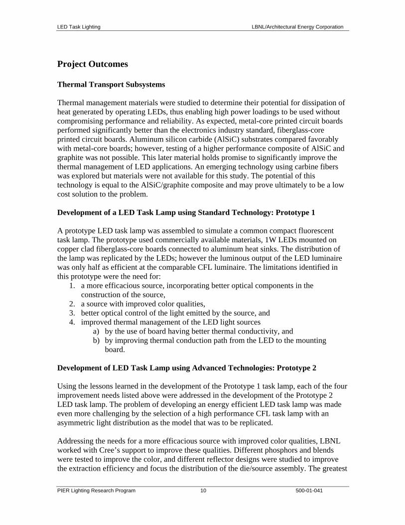
Project Outcomes Thermal Transport Subsystems Thermal management materials were studied to determine their potential for dissipation of heat generated by operating LEDs, thus enabling high power loadings to be used without compromising performance and reliability. As expected, metal-core printed circuit boards performed significantly better than the electronics industry standard, fiberglass-core printed circuit boards. Aluminum silicon carbide (AlSiC) substrates compared favorably with metal-core boards; however, testing of a higher performance composite of AlSiC and graphite was not possible. This later material holds promise to significantly improve the thermal management of LED applications. An emerging technology using carbine fibers was explored but materials were not available for this study. The potential of this technology is equal to the AlSiC/graphite composite and may prove ultimately to be a low cost solution to the problem. Development of a LED Task Lamp using Standard Technology: Prototype 1 A prototype LED task lamp was assembled to simulate a common compact fluorescent task lamp. The prototype used commercially available materials, 1W LEDs mounted on copper clad fiberglass-core boards connected to aluminum heat sinks. The distribution of the lamp was replicated by the LEDs; however the luminous output of the LED luminaire was only half as efficient at the comparable CFL luminaire. The limitations identified in this prototype were the need for:
1. a more efficacious source, incorporating better optical components in the construction of the source,
2. a source with improved color qualities, 3. better optical control of the light emitted by the source, and 4. improved thermal management of the LED light sources
a) by the use of board having better thermal conductivity, and b) by improving thermal conduction path from the LED to the mounting
board. Development of LED Task Lamp using Advanced Technologies: Prototype 2 Using the lessons learned in the development of the Prototype 1 task lamp, each of the four improvement needs listed above were addressed in the development of the Prototype 2 LED task lamp. The problem of developing an energy efficient LED task lamp was made even more challenging by the selection of a high performance CFL task lamp with an asymmetric light distribution as the model that was to be replicated. Addressing the needs for a more efficacious source with improved color qualities, LBNL worked with Cree’s support to improve these qualities. Different phosphors and blends were tested to improve the color, and different reflector designs were studied to improve the extraction efficiency and focus the distribution of the die/source assembly. The greatest

LED Task Lighting LBNL/Architectural Energy Corporation
PIER Lighting Research Program 11 500-01-041
increases in efficacy were realized by improvements in the performance of the die made by Cree during this time period. Ultimately, a standard package with a lambertian distribution was selected because it had improved efficacy of greater than 30 lumens per Watt and was to be introduced into the market within 2004. Greater attention was focused on optics that provided better control of the emitted light from the high brightness Cree light sources. High efficiency non-imaging optics were designed that replicated the desired distribution pattern defined by the CFL luminaire. The optics took the form of an asymmetric reflector that housed a single LED source, where each reflector subassembly replicated the desired distribution pattern. Hence, the loss of one or more sources only decreased the delivered light intensity without affecting the distribution pattern and no diffusers were required that decrease performance. The plastic reflector could easily be fabricated with injection molding techniques. The result was the development of a very efficient optical system that helped to reduce the number of LEDs. Finally, improved thermal management of the light source was obtained by using solder to provide an improved thermal attachment of the LED packages to an aluminum metal-core board. The metal-core boards were attached to aluminum sheets that acted as both heat sink and the housing envelope. The thermal conductivity was significantly improved and resulted in sources well below a junction temperature of 100C. Multiple heat sink designs were developed and some were constructed, but they proved unnecessary with the performance of the present design. The resultant was a lightweight LED task lamp that operated at 12 Watts of LED power and had the distribution and intensity of the 18 Watt CFL luminaire that it was replacing, demonstrating that a high efficiency task lamp can be constructed with LEDs, using available materials and good optical design. The results of this program have stimulated Luxo to generate a very esthetically improved version of this concept using their award winning Arketto task lamp to house three 3W (9 Watts total) LEDs to replace a 40 Watt halogen lamp, providing the same light output and distribution while providing very significant energy savings and vastly improved lamp life to the end user. Recommendations This project demonstrated the first LED task light to meet the light performance characteristics of a compact fluorescent luminaire while consuming less than 75% of the energy. Despite this significant success, the project also identified the limitations of the technology and where further product development would accelerate the commercial acceptance and functionality. This includes:
• Developing materials with higher thermal conductivity for higher power LED light sources.
• Exploring the incorporation of complimentary red LEDs with the white LED primary to improve color performance.

LED Task Lighting LBNL/Architectural Energy Corporation
PIER Lighting Research Program 12 500-01-041
• Developing cost effective power sources to control one or more types of LEDs. • Developing non-imaging optics that have high efficiency and that can provide a
more focused beam from the LED light sources. Conclusions This project has demonstrated that LEDs have reached the level of performance that will allow their incorporation into lighting products for general lighting applications, and that the technology can compete on an energy efficiency and cost-competitive basis with other task lighting solutions. This project demonstrated that the benefits of LED lighting should not be weighed entirely upon the efficacy (lumen per Watt) rating of the source but rather on efficiency of the lighting system to deliver light to the application. LEDs have reached the point where they can be considered appropriate for general lighting applications. Further development in the technologies of heat management, color quality, cost effective control of intensity, and improved optical control still remain critical issues to be addressed that will allow higher power levels and the wider implementation of the technology to more lighting applications. Programs to accelerate the knowledge and acceptance of this program could be facilitated through the emerging technology and rebate programs of California utilities. Benefits to California This product provides an energy efficient solution to task lighting. Luxo has taken advantage of the form factor of the small source size to significantly reduce the space requirements necessary for the luminaire, thus making its adoption for general use more likely. The general adoption of task lighting greatly benefits California by reducing the need of ambient electric lighting to provide lighting levels appropriate for all tasks. Therefore, the potential to reduce the electric load for lighting by the application of a user friendly task-ambient lighting system would be a significant benefit for commercial office spaces in California. The technologies employed in this program have a strong basis in the industries of California, with manufacturers based in Santa Barbara, San Jose, and Santa Rosa. Hence, this product incorporates technologies that were developed in California and that will be marketed throughout the United States, having a positive impact on the creation revenues for California companies and the creation of jobs within the state.

LED Task Lighting LBNL/Architectural Energy Corporation
PIER Lighting Research Program 13 500-01-041
Abstract This report describes the results of a research effort by LBNL under the PIER Lighting Research Program to develop a prototype LED task lamp for general illumination purposes. The project successfully demonstrated that LED technology is sufficiently advanced that an energy-efficient task light can be developed that meets or exceeds the performance characteristics of comparable halogen and compact fluorescent fixtures. The project demonstrated this through the development of a task lamp with industrial partners Luxo, Advance Transformer, Cree Lighting, and Permlight. The luminaire used ten one-Watt LED to replace a comparable 18-Watt compact fluorescent lamp, giving the same light distribution and workplane illuminance as the compact fluorescent fixture. The results of the study stimulated the luminaire manufacturer, Luxo, to commercialize the concept in the newly released Arketto LED lamp.

LED Task Lighting LBNL/Architectural Energy Corporation
PIER Lighting Research Program 14 500-01-041
Introduction Background and Overview LBNL is investigating current practices in commercial spaces relative to the use of task and ambient lighting in a project supported by the U.S. Department of Energy (DOE). One project activity includes an analysis of the market place relative to task and ambient lighting. This task was subcontracted to an nationally known lighting designer and researcher, Naomi Miller, to give an independent evaluation of the current technology and design practice for task and ambient lighting systems. A final report from Ms. Miller is publicly available, results from the draft report define two distinct markets for task lights: 1) portable task lamps and 2) furniture incorporated task lamps. The stand-alone portable task lamps are functionally characterized by a standard 120VAC cord and plug, and they incorporate controls and a power supply. The furniture task lamps are integrated into the design of the office furniture. These luminaries generally have less spatial flexibility and less control of the light distribution. In addition to the above research, LBNL has been performing basic and applied research in the development of LEDs, phosphors for LEDs, subassemblies and respective light sources and luminaires over the last four years. The DOE through various programs and a subcontract with Cree Lighting has funded this work. This project builds on experience developed in these previous efforts. Key findings and directions from this prior research include:
• The application to task lighting offers an immediate opportunity of introducing solid state light sources and providing end-user benefits in energy efficiency and optical properties not achievable with current sources.
• The relationship of LED device performance to the thermal characteristics of the device is crucial. The LED performance can be increased through improved thermal management of the die temperatures.
• Further improvements in LED performance can be achieved with improved die processing, phosphors, and micro-optics.
Market penetration of an LED-based task light into the general illumination market does not exist. A luminaire using this technology would represent the current state-of-the-art task light. In addition, the technological improvements in thermal management and LED device performance demonstrated in this project will have application to virtually all future LED luminaires. Project Objectives The goal of this project is to accelerate the use of energy efficient light emitting diode (LED) technology for general lighting applications by developing a task lamp utilizing

LED Task Lighting LBNL/Architectural Energy Corporation
PIER Lighting Research Program 15 500-01-041
high brightness LEDs in a consumer acceptable light fixture, and utilizing new materials with high thermal conductivity that will enhance lifetime and performance of the LEDs. The objectives of this project are to:
• Develop a thermally conductive sub-straight onto which LEDs are mounted that enhances the operation of LEDs at high power loadings while maintaining highest performance and reliability of the LED.
• Incorporate the latest developments in LED, phosphor and micro-optics, to achieve the highest system performance.
• Design, prototype, and transfer technology to luminaire manufacturers for the production of a commercial grade LED task light with efficiency equal to or greater than comparable incandescent and CFL luminaires.

LED Task Lighting LBNL/Architectural Energy Corporation
PIER Lighting Research Program 16 500-01-041
Project Approach Project Tasks The project’s work scope involved the following technical tasks:
2.2 Task 1. Development of Thermal Transport Subsystem 2.2 Task 2. Design Concept Development with Manufacturers 2.2 Task 3: Design LED Subsystem and Prototype LED based Task Light 2.2 Task 4. Technology Transfer Activities 2.2 Task 5. Production Readiness Plan 2.2 Task 6. Monthly Progress Report 2.2 Task 7. Annual Report 2.2 Task 8. Final Report
LED Task Lighting LBNL/Architectural Energy Corporation
PIER Lighting Research Program 17 500-01-041
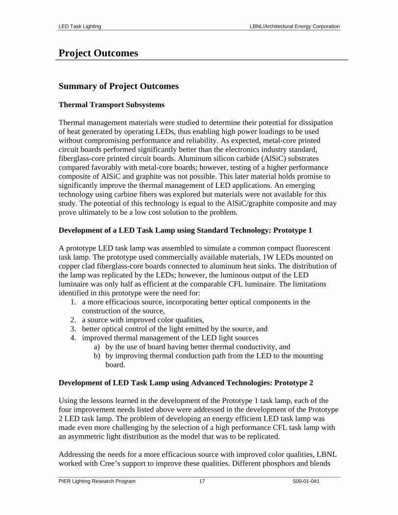
Project Outcomes Summary of Project Outcomes Thermal Transport Subsystems Thermal management materials were studied to determine their potential for dissipation of heat generated by operating LEDs, thus enabling high power loadings to be used without compromising performance and reliability. As expected, metal-core printed circuit boards performed significantly better than the electronics industry standard, fiberglass-core printed circuit boards. Aluminum silicon carbide (AlSiC) substrates compared favorably with metal-core boards; however, testing of a higher performance composite of AlSiC and graphite was not possible. This later material holds promise to significantly improve the thermal management of LED applications. An emerging technology using carbine fibers was explored but materials were not available for this study. The potential of this technology is equal to the AlSiC/graphite composite and may prove ultimately to be a low cost solution to the problem. Development of a LED Task Lamp using Standard Technology: Prototype 1 A prototype LED task lamp was assembled to simulate a common compact fluorescent task lamp. The prototype used commercially available materials, 1W LEDs mounted on copper clad fiberglass-core boards connected to aluminum heat sinks. The distribution of the lamp was replicated by the LEDs; however, the luminous output of the LED luminaire was only half as efficient at the comparable CFL luminaire. The limitations identified in this prototype were the need for:
1. a more efficacious source, incorporating better optical components in the construction of the source,
2. a source with improved color qualities, 3. better optical control of the light emitted by the source, and 4. improved thermal management of the LED light sources
a) by the use of board having better thermal conductivity, and b) by improving thermal conduction path from the LED to the mounting
board. Development of LED Task Lamp using Advanced Technologies: Prototype 2 Using the lessons learned in the development of the Prototype 1 task lamp, each of the four improvement needs listed above were addressed in the development of the Prototype 2 LED task lamp. The problem of developing an energy efficient LED task lamp was made even more challenging by the selection of a high performance CFL task lamp with an asymmetric light distribution as the model that was to be replicated. Addressing the needs for a more efficacious source with improved color qualities, LBNL worked with Cree’s support to improve these qualities. Different phosphors and blends

LED Task Lighting LBNL/Architectural Energy Corporation
PIER Lighting Research Program 18 500-01-041
were tested to improve the color, and different reflector designs were studied to improve the extraction efficiency and focus the distribution of the die/source assembly. The greatest increases in efficacy were realized by improvements in the performance of the die made by Cree during this time period. Ultimately, a standard package with a lambertian distribution was selected because it had improved efficacy of greater than 30 lumens per Watt and was to be introduced into the market within 2004. Greater attention was focused on optics that provided better control of the emitted light from the high brightness Cree light sources. High efficiency non-imaging optics were designed that replicated the desired distribution pattern defined by the CFL luminaire. The optics took the form of an asymmetric reflector that housed a single LED source, where each reflector subassembly replicated the desired distribution pattern. Hence, the loss of one or more sources only decreased the delivered light intensity without affecting the distribution pattern and no diffusers were required that decrease performance. The plastic reflector could easily be fabricated with injection molding techniques. The result was the development of a very efficient optical system that helped to reduce the number of LEDs. Finally, improved thermal management of the light source was obtained by using solder to provide an improved thermal attachment of the LED packages to an aluminum metal-core board. The metal-core boards were attached to aluminum sheets that acted as both heat sink and the housing envelope. The thermal conductivity was significantly improved and resulted in sources well below a junction temperature of 100C. Multiple heat sink designs were developed and some were constructed, but they proved unnecessary with the performance of the present design. The resultant was a lightweight LED task lamp that operated at 12 Watts of LED power and had the distribution and intensity of the 18 Watt CFL luminaire that it was replacing, demonstrating that a high efficiency task lamp can be constructed with LEDs, using available materials and good optical design. The results of this program have stimulated Luxo to generate a very esthetically improved version of this concept using their award winning Arketto task lamp to house three 3W (9 Watts total) LEDs to replace a 40 Watt halogen lamp, providing the same light output and distribution while providing very significant energy savings and vastly improved lamp life to the end user. Development of Thermal Transport Subsystem This section describes the results of the exploration of novel heat-sinking technologies for use in LED-integrating fixtures, specifically the desktop task-lamp. As a transition is made from standard 5mm LED packages to high-power lamps, operating at powers of 1-5 Watts, the issue of thermal management becomes increasingly vital to the efficiency and lifetime of the diodes. Increased junction temperatures can degrade the wiring used in connecting the LED chip to the package, the phosphor used in

LED Task Lighting LBNL/Architectural Energy Corporation
PIER Lighting Research Program 19 500-01-041
converting the blue or UV light to white emission, and the encapsulant material used in the lens. Furthermore, an increased junction temperature results in both reduced luminous efficiency (particularly for AlInGaP based red and amber LEDs) and a red shifting of the emission wavelength. It is essential that heat be removed from the LED package – LumiLeds rates the maximum temperature of the junction at 120°C and the package at 105°C. This is typically accomplished by mounting the LED onto a larger, thermally conductive heat-sink. The use of fiber-core PCBs is common in surface mounting electronic components, but results in junction temperatures well above the recommended values. In this study, researchers compare standard fiber-core boards to two types of metal-core boards, aluminum and copper, as well as to more novel structures, incorporating graphite and carbon wires. Experimental Setup The LEDs used in this study were off-the-shelf 1W white Luxeon packages from LumiLeds. The emission pattern was either batwing or Lambertian, although there should be no effect of that pattern on the thermal characteristics of the device. The packages were then mounted onto the boards using a thermally conductive, yet electrically insulating silicone joint compound (Ther-o-link 1000, Aavid Thermal Technologies, 0.73 Watt/(m°C)). To begin analyzing the thermal characteristics of an operating device, a calibration is made of the voltage drop across the LED as a function of ambient temperature. The device is placed in an oven, and 1mA of current is passed through the diode. The voltage across the junction is measured as the temperature of the oven is varied, allowing for the device to reach an equilibrium temperature at each point. Figure 1 shows the experimental setup used in generating the calibration curves. To determine junction temperature at an operating current of 300-350mA, the device is pulsed, with the current in the LED varying between the desired final operating current and 1mA. The period of the pulse is set at 100msec with an off-time (I = 1mA) of 6.8msec. It is assumed that the off-time is sufficiently short so that no cooling occurs during that interval. The voltage drop across the device at a current of 1mA is then compared to the calibration curve to back-out the operating temperature – a specific voltage drop is correlated to a specific junction temperature. Figure 2 shows a calibration curve for a Luxeon Lambertian package. The schematic of the split-current circuit diagram is shown in Figure 3.

LED Task Lighting LBNL/Architectural Energy Corporation
PIER Lighting Research Program 20 500-01-041
oven
temp
V
power supply
2.4 kΩ
+6
oven
temptemp
VV
power supply
2.4 kΩ
+6
Voltage vs. Temperature Calibration
2.38
2.4
2.42
2.44
2.46
2.48
2.5
2.52
2.54
2.56
2.58
0 20 40 60 80 100
Temperature (Celsius)
Dio
de V
olta
ge (V
)
Figure 1: Thermal calibration setup layout Figure 2: Sample calibration curve
V1
+12
10 kΩ
V2 current probe
V1V1
+12
10 kΩ10 kΩ
V2V2 current probe
adhesive
LED chip
heatsink
adhesive
LED chip
heatsink
Figure 3: Differential voltage measurement circuit Figure 4: Experimental schematic; adhesive is Thero-link compound, approximately 0.5mm thick.
Results Baseline Material: Fiberglass-core PCB The most common PCB material is a fiberglass-core board with a copper trace for mounting. Luxeon LEDs were mounted on this board using the Ther-o-link material (Figure 4), and the junction temperature measured in the manner detailed in the previous section for both 50mA and 300mA operation. At 50mA (92% duty cycle), the ∆V was 2.56V, corresponding to a junction temperature of 40°C. At 300mA (d.c. = 92%), the voltage difference was 2.44V, corresponding to a junction temperature of 120°C. Extrapolating this to 350mA yields a junction temperature of 136°C at that current. Metal-core PCB: Copper (Bergquist Co.)

LED Task Lighting LBNL/Architectural Energy Corporation
PIER Lighting Research Program 21 500-01-041
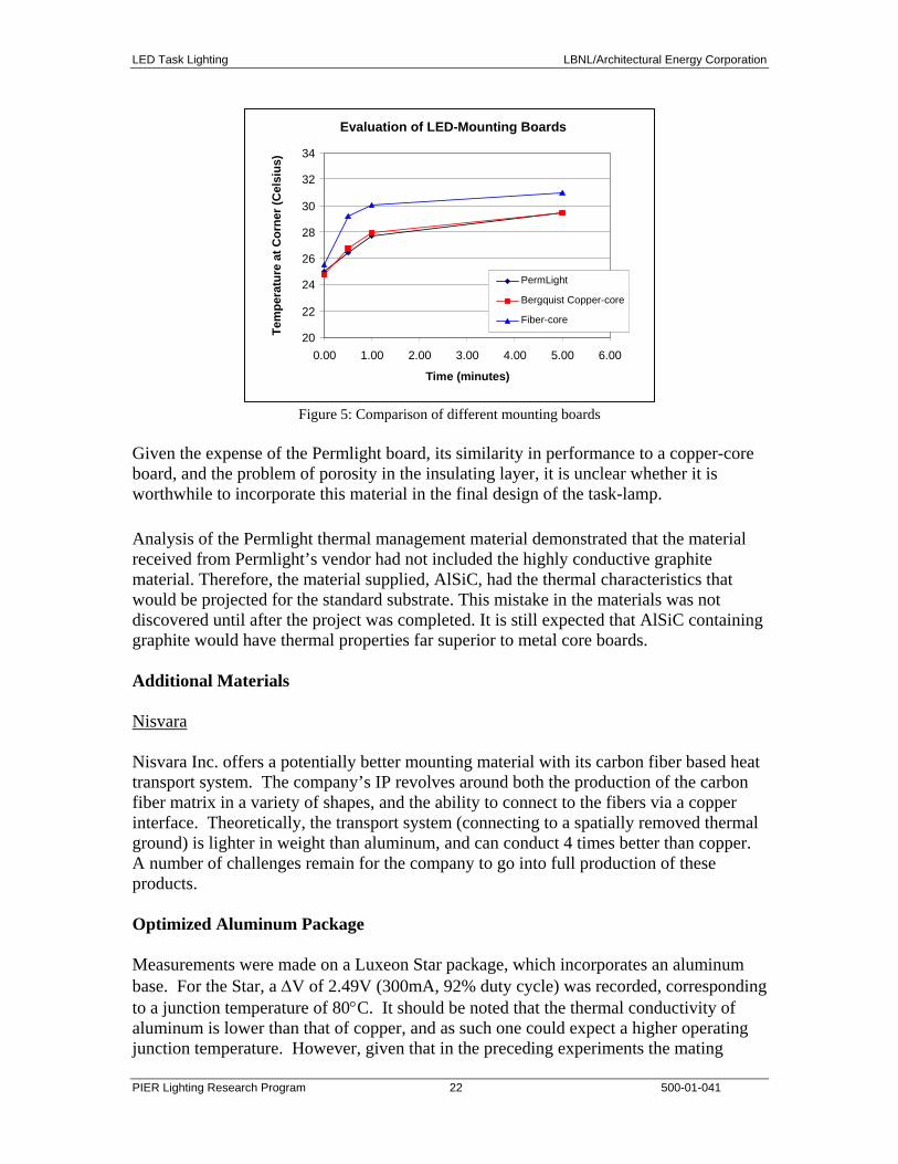
The metal-core board consists of a copper trace laid upon a thin insulator layer on top of a thicker metal heatsink. The insulator should be as thermally conductive as possible while providing electrical isolation. The underlying metal core is typically either copper or aluminum. Copper offers a better thermal conductivity (260 Watt/m°C, versus 173 Watt/m°C for Al) and a smaller thermal expansion coefficient (18 ppm/°C vs. 24 ppm/°C for Al). The drawback for using Cu is the added weight penalty. Measurement of a Luxeon LED mounted to a Copper-core board using the ther-o-link compound yielded a ∆V of 2.34V (at 350mA), corresponding to a junction temperature of 126°C. Permlight Board Through collaboration with Permlight, LBNL has acquired 1.5x1.5 in2 boards with a graphite core surrounded by a silicon carbide ceramic substrate impregnated with aluminum (AlSiC). Mounting the LED using the ther-o-link compound yielded a ∆V of 2.42V (at 350mA), corresponding to a junction temperature of 127°C. However, a problem arose when a Luxeon LED was soldered to a copper pattern on the Permlight board. Upon probing, it became apparent that the circuit was shorted due to the porosity of the insulating SiO2 overcoat. Additional comparison between Permlight and copper A comparison between the Permlight board and a Bergquist copper-core board of similar area showed nearly identical thermal spreading characteristics. Heat was applied to the center of each board by using a soldering iron, and the temperature measured at a corner via thermocouple. During the measurements, each board was placed on a large Aluminum block that served as a heatsink. The temperature of the Aluminum did not change significantly during the course of the measurement. Figure 5 shows the temperature at the corner as a function of time for the copper-core, Permlight, and fiber-core boards. Additionally, a measurement of the temperature at the center of the board was made at the 5-minute mark. For both the copper-core and Permlight board, the value was 29.4°C – the same as at the corner – while for the fiber-core board, the center temperature was higher: 33.9°C as compared to 31.0°C at the corner.
LED Task Lighting LBNL/Architectural Energy Corporation
PIER Lighting Research Program 22 500-01-041
Evaluation of LED-Mounting Boards
20
22
24
26
28
30
32
34
0.00 1.00 2.00 3.00 4.00 5.00 6.00
Time (minutes)
Tem
pera
ture
at C
orne
r (C
elsi
us)
PermLight
Bergquist Copper-core
Fiber-core
Figure 5: Comparison of different mounting boards
Given the expense of the Permlight board, its similarity in performance to a copper-core board, and the problem of porosity in the insulating layer, it is unclear whether it is worthwhile to incorporate this material in the final design of the task-lamp. Analysis of the Permlight thermal management material demonstrated that the material received from Permlight’s vendor had not included the highly conductive graphite material. Therefore, the material supplied, AlSiC, had the thermal characteristics that would be projected for the standard substrate. This mistake in the materials was not discovered until after the project was completed. It is still expected that AlSiC containing graphite would have thermal properties far superior to metal core boards. Additional Materials Nisvara Nisvara Inc. offers a potentially better mounting material with its carbon fiber based heat transport system. The company’s IP revolves around both the production of the carbon fiber matrix in a variety of shapes, and the ability to connect to the fibers via a copper interface. Theoretically, the transport system (connecting to a spatially removed thermal ground) is lighter in weight than aluminum, and can conduct 4 times better than copper. A number of challenges remain for the company to go into full production of these products. Optimized Aluminum Package Measurements were made on a Luxeon Star package, which incorporates an aluminum base. For the Star, a ∆V of 2.49V (300mA, 92% duty cycle) was recorded, corresponding to a junction temperature of 80°C. It should be noted that the thermal conductivity of aluminum is lower than that of copper, and as such one could expect a higher operating junction temperature. However, given that in the preceding experiments the mating

LED Task Lighting LBNL/Architectural Energy Corporation
PIER Lighting Research Program 23 500-01-041
between the LED and the board was accomplished by using a poor thermal conductor, this value is not surprising. In their package, LumiLeds uses a 0.01” thick adhesive with a thermal conductivity of around 1 Watt/m°C. The Ther-o-link (0.73 Watt/m°C) used in LBNL experiments was approximately 0.5mm thick (0.02”). It is likely that a better mounting design – both in terms of material used and thickness – will yield junction temperatures below 80°C (at 300mA). Conclusions and Suggestions for Future Work Based on the measurement shown in Figure 5, it is clear that, for the case of non-integrated mounting boards, copper is the best available choice. The Bergquist board shows properties on par with the Permlight board, but at a lower cost and greater (and easier) availability. Measurement of the junction temperature on the different boards confirms this assessment, although it also indicates that the best design is one in which the LED is properly mounted onto the board, as in the case of the Luxeon Star. It is quite likely that the resulting high junction temperatures (well above 100°C at 350mA) are due to the Ther-o-link compound used in the mounting. One possible solution is to incorporate a high thermal conductivity epoxy. Tra-Con Inc. for example, produces a diamond epoxy (Supertherm 2003) with a thermal conductivity of 2.57 Watt/(m°C) – a factor of 3 higher than the Ther-o-link compound – while remaining electrically insulating. The drawback in using this material is that it must be kept at -40°C for storage. In the use of the Cree packages, it may be possible to solder the base of the lamp to the board directly (assuming that, unlike in the Luxeon lamp, the base is isolated from the diode). A typical thermal conductivity of solder is around 50 Watt/m°C, almost 2 orders of magnitude better than Ther-o-link, and 20 times better than an epoxy. First Prototype Task Light The design of prototype #1 was based on the low cost, commercially available Luxo Ledu CFL desk lamp, shown in Figure 6. The lamp head contains a 13 Watt compact fluorescent lamp, with a reflector behind it to direct as much the light towards the task (see Fig. 6, inset).
Figure 6: Luxo Ledu CFL desk lamp. Inset: Close-up of the lamp head and reflector
LED Task Lighting LBNL/Architectural Energy Corporation
PIER Lighting Research Program 24 500-01-041
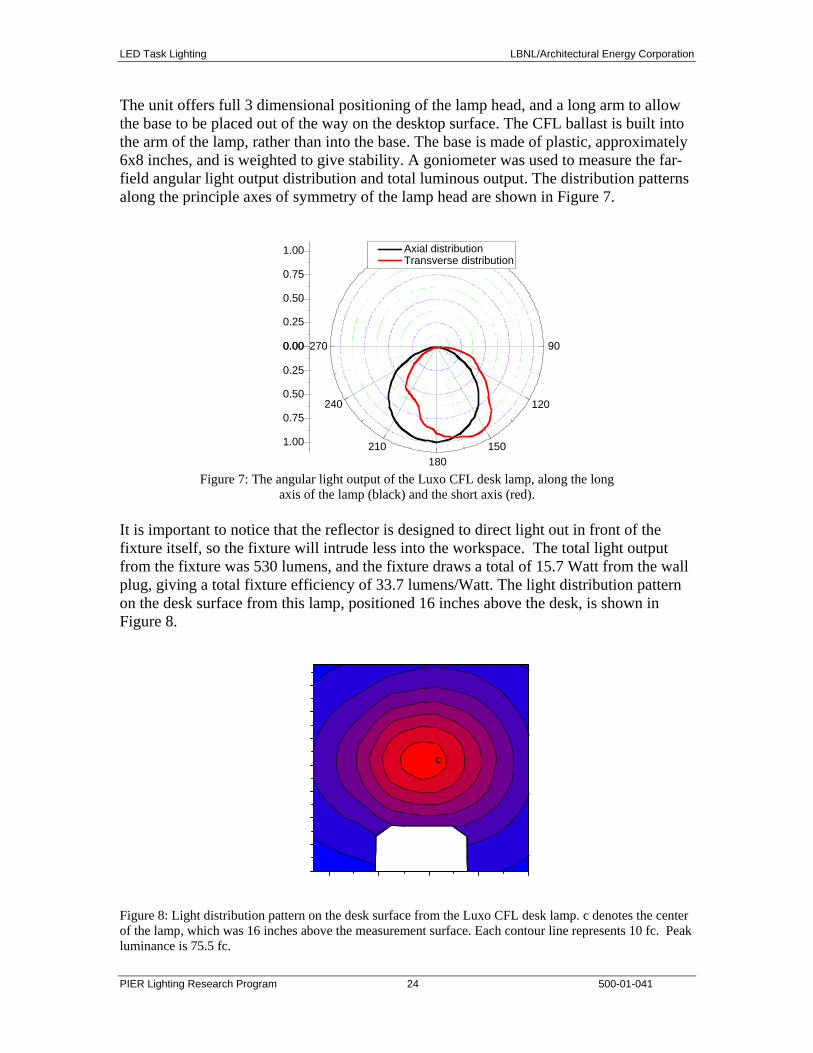
The unit offers full 3 dimensional positioning of the lamp head, and a long arm to allow the base to be placed out of the way on the desktop surface. The CFL ballast is built into the arm of the lamp, rather than into the base. The base is made of plastic, approximately 6x8 inches, and is weighted to give stability. A goniometer was used to measure the far-field angular light output distribution and total luminous output. The distribution patterns along the principle axes of symmetry of the lamp head are shown in Figure 7.
0.00
0.25
0.50
0.75
1.00
90
120
150180
210
240
2700.00
0.25
0.50
0.75
1.00
Axial distribution Transverse distribution
Figure 7: The angular light output of the Luxo CFL desk lamp, along the long
axis of the lamp (black) and the short axis (red). It is important to notice that the reflector is designed to direct light out in front of the fixture itself, so the fixture will intrude less into the workspace. The total light output from the fixture was 530 lumens, and the fixture draws a total of 15.7 Watt from the wall plug, giving a total fixture efficiency of 33.7 lumens/Watt. The light distribution pattern on the desk surface from this lamp, positioned 16 inches above the desk, is shown in Figure 8.
c
Figure 8: Light distribution pattern on the desk surface from the Luxo CFL desk lamp. c denotes the center of the lamp, which was 16 inches above the measurement surface. Each contour line represents 10 fc. Peak luminance is 75.5 fc.

LED Task Lighting LBNL/Architectural Energy Corporation
PIER Lighting Research Program 25 500-01-041
Design of Prototype #1 In order to convert the CFL fixture to an LED fixture, researchers retained the structure of the original and simply replaced the CFL head with several LEDs on a circuit board and heat sink. The LED ballast was built into the base plate of the fixture in the prototype, rather than in the arm. The resulting design is shown in Figure 9.
Figure 9: Prototype #1, LED task lamp LEDs for light generation The LEDs used in prototype #1 were 1 Watt Luxeon emitter packages from LumiLeds. These LEDs give off approximately 25 lumens when running at full current (1 Watt of power in), and they represent the current standard for high power white LEDs in the marketplace. The packages are approximately 1 cm in diameter, with solderable leads on each side, and a metal plug in the middle that conducts heat away from the LED die to the surrounding material. The LEDs can be sold with a high-dome or a low-dome casing, which give different spatial light output, either Lambertian (high-dome) or bat-wing (low-dome). The light distribution pattern is available form LumiLeds on their web site, www.lumileds.com. In order to equal the total luminous output of the Luxo CFL desk lamp, approximately 20 Luxeon 1W LEDs are needed. It was decided to lower this number to ten LEDs, due to the excessive heating that would arise from packing 20 LEDs into such a small area. Output distribution simulations In order to approximate the light distribution from the Luxo lamp, shown in Figure 7, both Lambertian and bat-wing style LEDs were used in the construction of prototype #1. The relative number and orientation of each type were determined by fitting the curves in Figure 7 with a combination of the output curves of the two types of LEDs. The result is

LED Task Lighting LBNL/Architectural Energy Corporation
PIER Lighting Research Program 26 500-01-041
shown in Figure 10, requiring that lamp use 7 Lambertian packages and 3 bat-wing packages, at an angle of 30 degrees from one another (see Figure 11).
0.00
0.25
0.50
0.75
1.00
90
120
150180
210
240
2700.00
0.25
0.50
0.75
1.00
Inte
nsity
(nor
mal
ized
)
Simulated Axial Distribution Simulated transverse Distribution
Figure 10: Simulated Distribution from 7 Lambertian and 3 bat-wing LEDs for the prototype lamp head. Thermal management of the LEDs The thermal management of the LEDs is critically important for several reasons. If the LED junctions overheat, the device lifetime will shorten dramatically, and the efficiency will decrease. If the temperature rises enough, the LED will fail altogether. The maximum working junction temperature for a LumiLeds Luxeon emitter is 135°C. In addition, the fixture temperature must stay below a reasonable level, so that the user is not burned by incidental contact with the lamp head. Since prototype #1 was designed to use the current standard technology, researchers mounted the LED emitter packages onto a standard fiberglass-core copper-clad circuit board. The heat sink plug in the emitter package was connected to the board using thermally conductive grease (Ther-o-link 1000 joint compound). These boards were then mounted to aluminum heat sinks using a thermally conductive silicone adhesive (MG chemicals #1032). The resultant LED ‘lamp’ is shown in Figure 11. The LED lamp head design, owing mostly to the heat sinks, is significantly heavier than the original plastic Luxo CFL lamp head. However, it was still possible to connect the new lamp head to the original fixture arm, to keep the flexibility in lamp position. In a completely new design, the support for the LED lamp head would be stronger, but the current design allowed the full range of motion and was relatively stable.
LED Task Lighting LBNL/Architectural Energy Corporation
PIER Lighting Research Program 27 500-01-041
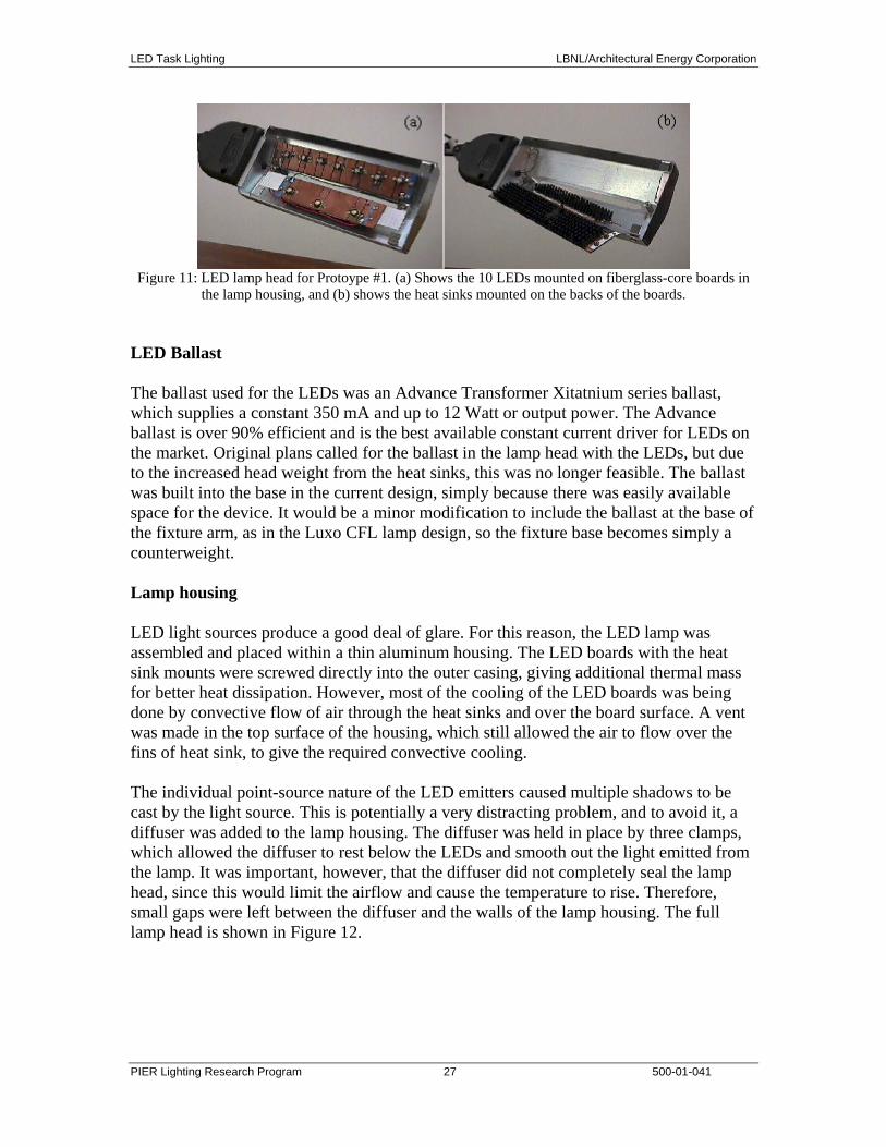
Figure 11: LED lamp head for Protoype #1. (a) Shows the 10 LEDs mounted on fiberglass-core boards in
the lamp housing, and (b) shows the heat sinks mounted on the backs of the boards. LED Ballast The ballast used for the LEDs was an Advance Transformer Xitatnium series ballast, which supplies a constant 350 mA and up to 12 Watt or output power. The Advance ballast is over 90% efficient and is the best available constant current driver for LEDs on the market. Original plans called for the ballast in the lamp head with the LEDs, but due to the increased head weight from the heat sinks, this was no longer feasible. The ballast was built into the base in the current design, simply because there was easily available space for the device. It would be a minor modification to include the ballast at the base of the fixture arm, as in the Luxo CFL lamp design, so the fixture base becomes simply a counterweight. Lamp housing LED light sources produce a good deal of glare. For this reason, the LED lamp was assembled and placed within a thin aluminum housing. The LED boards with the heat sink mounts were screwed directly into the outer casing, giving additional thermal mass for better heat dissipation. However, most of the cooling of the LED boards was being done by convective flow of air through the heat sinks and over the board surface. A vent was made in the top surface of the housing, which still allowed the air to flow over the fins of heat sink, to give the required convective cooling. The individual point-source nature of the LED emitters caused multiple shadows to be cast by the light source. This is potentially a very distracting problem, and to avoid it, a diffuser was added to the lamp housing. The diffuser was held in place by three clamps, which allowed the diffuser to rest below the LEDs and smooth out the light emitted from the lamp. It was important, however, that the diffuser did not completely seal the lamp head, since this would limit the airflow and cause the temperature to rise. Therefore, small gaps were left between the diffuser and the walls of the lamp housing. The full lamp head is shown in Figure 12.

LED Task Lighting LBNL/Architectural Energy Corporation
PIER Lighting Research Program 28 500-01-041
Figure 12: The prototype lamp head with diffuser to even out the light distribution. Analysis of Prototype #1 After final assembly, prototype #1 was measured for comparison with the Luxo CFL fixture. First, the output distribution was measured with the goniometer. The results of that measurement are shown in Figure 13. Notice that there is a small dip in the center of the distribution in the axial direction. Researchers believe this is due to the relatively large spacing between the LEDs, which was necessary to keep the heat load down to a manageable level. Also, notice that the transverse distribution does not show the same asymmetric profile seen in the Luxo CFL fixture, which was expected from the simulations. This is due to constraints placed by the lamp housing. The LEDs were mounted inside the housing each with a 15o angle from vertical. In fact, in order to get the asymmetric distribution, they should have been mounted slightly off center, the same as tilting the lamp head forward by about a 10o angle. This could easily be addressed with slight modifications to the lamp housing design.
0.00
0.25
0.50
0.75
1.00
90
120
150180
210
240
2700.00
0.25
0.50
0.75
1.00
Prototype #1 Axial distribution Prototype #1 Transverse distribution
Figure 13: Goniometer measurements of prototype #1. The dip in the middle of the distribution appears to be due to the uneven spacing of the LEDs. In addition, the light distribution pattern on a desk surface from the prototype lamp was measured. These measurements were performed with the lamp head 16 inches above the desk surface. The results are shown in Figure 14. Notice that the distribution falls off

LED Task Lighting LBNL/Architectural Energy Corporation
PIER Lighting Research Program 29 500-01-041
more rapidly at the edges than the distribution of the Luxo CFL lamp, Figure 8. Also, notice the decrease in intensity just in the center of the distribution, which was discussed above and appears to be due to the spacing of the individual LED sources. The total luminous output of the prototype was approximately ½ the output of the Luxo lamp, at 211 lumens. The unit draws 13.3 Watt from the wall plug, giving a fixture efficiency of 15.9 lum/Watt, significantly lower than the CFL fixture. However, intensity of light sent to the central region of the prototype lamp is nearly as high as that of the Luxo lamp. The CFL lamp gave a maximum of 75 footcandles on the desk surface at the center of the distribution, whereas the LED prototype gives 60 footcandles. Therefore, it appears that the prototype lamp is almost as bright in the direct task-lit area, but that light falls off much faster with distance away from the center point.
c
Figure 14: Light distribution pattern on the desk surface from the LED prototype desk lamp. c denotes the center of the lamp, which was 16 inches above the measurement surface. Each contour line represents 8.12 fc. Peak luminance is 60.3 fc. Finally, the temperature of the LED prototype lamp was measured, in order to ensure that the LED junctions did not overheat. The air inside the LED housing reached a steady 45o
C after 30 minutes of operating. The boards on which the LEDs were mounted reached 85o C during that same time. Assuming 25o C/Watt for the difference between the board and the junction, as estimated by LED experts for the emitter packages, the junction temperature for these LEDs was approximately 110o C. This is hot, but still below the maximum specified temperature. The outside of the lamp housing became warm to the touch, but not hot, and it definitely would not burn skin or other office material. Improvements for prototype #2 Heat sink choice Thermal conductivity measurements on a number of mounting boards have indicated that a copper-core PCB allows for greater conduction and heat dissipation than the fiberglass-

LED Task Lighting LBNL/Architectural Energy Corporation
PIER Lighting Research Program 30 500-01-041
core equivalent. As such, the first step in improving on the thermal characteristics of the prototype would be the replacement of the circuit board as discussed earlier with a metal-core board. LED mounting The thermal conductivity of the Ther-o-link compound used to mount the LED packages to the PCB board is only 0.73 Watt/m°C. To improve the connection between the LED and the board, and to ensure proper heat dissipation, it is recommended that a thermally conductive epoxy be used instead. Tra-Con, inc. produces a die-attach epoxy that is both thermally conductive (2.57 Watt/m°C, a factor of 3 improvement over Ther-o-link) and electrically insulating – a necessity when used Luxeon or Cree lamp packages. The disadvantage of this material is the need for storage at -40°C to prevent curing. LED Efficacy The efficacy of the LEDs limited the performance of Prototype 1 and consequently increased the thermal management requirements of the system. The efficacy can be increased by improvements in the component structure of the LED assembly, including improved optics for the reflector surrounding the die, improved extraction efficiency from the die into the encapsulant, improved quantum efficiency of the phosphors, and improve quantum efficiency of the die. Optics As discussed earlier, the light distribution still exhibited some of the effects of using discreet point sources, such as multiple shadows. Although using a diffuser alleviates some of these problems, the result can be a loss in light output. An alternative approach is the design of non-imaging optics that can be used over each separate LED, or over the aggregate, to direct and mix the light to produce the desired desktop pattern. Ultimately, this would result in a luminaire design that is truly tailored around LEDs. Second Prototype Task Light Using the lessons learned in the development of the Prototype 1 task lamp, each of the four improvement needs listed above were addressed in the development of the Prototype 2 LED task lamp. The problem of developing an energy efficient LED task lamp was made even more challenging by the selection of a high performance CFL task lamp with an asymmetric light distribution as the model that was to be replicated. The design of the LED task lamp was based upon the photometric performance of the Luxo 01A Vision asymmetric task luminaire (Figure 15).

LED Task Lighting LBNL/Architectural Energy Corporation
PIER Lighting Research Program 31 500-01-041
Figure 15. LED task lamp with two rows of five lamps each. Each row can rotate around its axis.
The intent of the design was to maintain the existing illuminance pattern of this luminaire on the workplane, while replacing the compact fluorescent lamp (CFL) with LEDs as the light source. Design of Advanced LED Subsystem During the course of developing their XLamp package, Cree Lighting sent LBNL a number of unencapsulated XB900 chips, wire-bonded and centered in a reflector cup. The goal of this study was to develop a method for mixing a Ce:YAG phosphor into a silicone encapsulant, and dispense the mixture into the reflector such that the final emission was both white and Lambertian. This report will describe the methodology for the encapsulation process, as well as detail some of the results. The Ce:YAG phosphor used was provided by Cree Lighting. The 2-part (1:1) silicone encapsulant (OE4000) was provided by Dow Corning as their highest refractive index (n = 1.466 at 632nm) non-liquid-upon-curing material. It has been indicated that Dow Corning will eventually have a non-liquid encapsulant with n = 1.52. Process: Mix phosphor (at given weight percent) into OE4000 Ultrasonic for 5’ Remove trapped air bubbles by placing mixture in vacuum for 60’ (approximately) Place drop of mixture in reflector cup (researchers did not have accurate control of the
amount – a use of a micropipette would provide the necessary control) Pull on the LED in vacuum for 10’ (again, to remove trapped air bubbles) Cure encapsulant at 80°C for a minimum of 2 hours Figure 16 shows the angular intensity distribution of an unencapsulated XB900 die in a reflector at 90°, as compared to the typical distribution for an encapsulated die. Although the shape of the phosphor/silicone meniscus varied as a result of the size of the mixture drop that was placed in the reflector, the intensity distribution was relatively insensitive to the final curvature.

LED Task Lighting LBNL/Architectural Energy Corporation
PIER Lighting Research Program 32 500-01-041
LBNL tested mixtures with varying percentages of phosphor for color temperature: 10%, 7.5%, 5%, and 2.5% by weight Ce:YAG to OE4000. Both the 5% and 2.5% mixtures resulted in bluish emission off the Planckian curve. For the 7.5% blend, the color temperature was approximately 4700K, with a CRI of 65. For 10%, the temperature averaged 4300K, and the CRI was 66. Figure 17 shows the variation in CRI and CCT as a function of angle for a XB900 die encapsulated in a 10% by weight phosphor mixture. Researchers also measured encapsulated dies provided by Cree Lighting, both with and without a polycarbonate lens. Figure 18 shows the goniometer data for the Cree LEDs; Figure 19 shows the variation in CCT and CRI with angle. During this development phase, LBNL was in continuous communication with the Cree development group in Santa Barbara, CA, who were concurrently developing encapsulated die in a standard format, without focusing micro-optics. In the final prototype, this standard format product with a lambertian distribution was used. This decision was motivated by the desired to use materials that would be available in the market within a short period of time. Since there was little optical control of the new Cree source, the optics would be controlled by the development of an efficient asymmetric reflector. The color temperature of the Cree light source (> 5500 K) was higher than desired, but efficacy of the source, between 30 and 35 lumens per Watt, was significantly higher than the LEDs used in Prototype 1.
Angular distribution of relative luminous intensity (%)
0
10
20
30
40
50
60
70
80
90
1000
5 10 15 2025
3035
4045
5055
6065
7075
80
85
90
95
100100
95
90
85
80
7570
6560
5550
4540
3530
2520 15 10 5
Figure 16: Angular distribution for the XB900 chip in a reflector; bare (red)
and with 10% phosphor encapsulant (black)

LED Task Lighting LBNL/Architectural Energy Corporation
PIER Lighting Research Program 33 500-01-041
CCT and CRI as a function of off-axis angle
2000
3000
4000
5000
6000
7000
8000
9000
0 20 40 60 80
Angle (off-axis)C
CT
(K)
0102030405060708090100
CR
I
CCT CRI
Figure 17: CCT and CRI uniformity for 10% phosphor encapsulation
Angular distribution of relative luminous intensity (%)
0
10
20
30
40
50
60
70
80
90
1000
5 10 15 2025
3035
4045
5055
6065
7075
80
85
90
95
100100
95
90
85
80
7570
6560
5550
4540
3530
2520 15 10 5
no lensfull pkg
Figure 18: Angular distribution for the XB900 chip in a reflector; with lens (red) and phosphor only (black)
CCT and CRI as a function of off-axis angle (CREE)
2000
3000
4000
5000
6000
7000
8000
9000
0 20 40 60 80
Angle (off-axis)
CC
T (K
)
0
10
20
30
40
50
60
70
80
90
100
CR
I
CCT CCT (full) CRI CRI (full)
Figure 19: CCT and CRI uniformity for LEDs provided by Cree Lighting.
‘Full’ indicates phosphor plus polycarbonate lens

LED Task Lighting LBNL/Architectural Energy Corporation
PIER Lighting Research Program 34 500-01-041
Task Lamp Design The LED task luminaire designed by LBNL contains 10 LED lamp units, in two rows of 5 lamps each as shown in Figure 20. This figure is a three dimensional simulation of the lamp reflector viewed looking up into the reflector cups, where the small black dot indicates where the LED would be located. Each row of lamps is able to rotate ± 10 degrees around the central axis of the reflector, and the two rows rotate simultaneously. Figure 21 demonstrates the two extremes of the rotation, looking at the end of the rows.
Figure 20. LED task lamp with two rows of five lamps each. Each row can rotate around its axis.
Figure 21. Inward and outward rotation of LEDs around the central axis.
The design of the reflector cups was developed using a ray tracing simulation program, TracePro, with the intent of simulating the illuminance pattern of the Luxo 01A Vision asymmetric task luminaire as given in Figure 15. The illuminance pattern was not segmented into different areas for the separate LEDs, but rather each reflector replicated the entire distribution pattern. Hence, the reflectors have a cumulative effect in raising the

LED Task Lighting LBNL/Architectural Energy Corporation
PIER Lighting Research Program 35 500-01-041
overall illuminance within the pattern and the failure of one source will not be disruptive to that distribution pattern. The design of the reflector cups assumed a point source with a Lambertian distribution. Measurements in the far field of the LEDs being used verified this assumption. The calculations also assumed that each source would have an efficacy of 25 lumens per Watt and that the reflector was 90% efficient. The resultant simulations indicate that ten 1-Watt LEDs in separate reflectors would provide the same illumance as the 18 Watt CFL in the Luxo 01A Vision task lamp. Each reflector has the dimension of 46 X 32 X 22 mm (LxWxH). Once the simulation program generated a solid model of the reflector cup having the desired optical properties, the information was transferred to fabrication equipment. The prototype reflector pieces for the task lamp were fabricated by a stereo-lithography (SLA) process and modified to be able to take the new Cree XLamp prototype mounted on a heat sink (Figure 22).
Figure 22. CAD model of LED tasklamp reflector (left) and the heat sink mounted Cree XLamp prototype (right)
Two different types of coatings were applied to the reflector surfaces in order to test the output with both specular and diffuse reflectance. In case of the specular coating (Figure 23), the surface of the reflector was smoothed by the application of two very thin UV cured epoxy layers prior to aluminizing the surface. No treatment was applied to the other reflector before application of the diffuse white paint coating (Figure 24).

LED Task Lighting LBNL/Architectural Energy Corporation
PIER Lighting Research Program 36 500-01-041
Figure 23. SLA prototype reflector with specular metal coating.
Figure 24. SLA prototype reflector with diffuse white paint coating.
Results of Testing and Simulations Testing performed on the SLA reflectors measured the spatial intensity distribution pattern relative to the simulated reflector. A comparison of the measured values for the specular reflector to the simulated values is given for the centerline distribution in Figure 25.

LED Task Lighting LBNL/Architectural Energy Corporation
PIER Lighting Research Program 37 500-01-041
The simulated distribution has a broader distribution with a maximum value further from the optical axis of the source, the “0” set point, than the measured distribution. The difference in the observed and simulated distributions may be attributed to several factors:
1) The simulation assumed a point source. Given the size of the source and its close proximity of the source to the reflector walls, this assumption is not entirely valid, introducing some error into the simulation.
2) The surfaces of the reflector were not as smooth as those used in the simulations. This is visible in the photographs of both reflector surfaces (Figures 23 and 24), being more pronounced in the white diffuse reflector where a smoothing epoxy was not used.
3) The accuracy of the dimensional replication of the solid model is limited by the SLA prototyping process and hence limits the development of exact replicas of the simulated reflectors.
0
200
400
600
800
1000
1200
-100 0 100 200 300 400 500 600 700 800 900 1000
[mm]
a.u.
measuredsimulatederror
Figure 25. Specular Reflector: simulated and measured spatial output
Figure 25 represents the results of a single reflector, as the five reflectors are aligned in a row, the resultant distribution will be broader like the simulation because of the spatial separation of the sources.

LED Task Lighting LBNL/Architectural Energy Corporation
PIER Lighting Research Program 38 500-01-041
0
200
400
600
800
1000
1200
-100 0 100 200 300 400 500 600 700 800 900 1000[mm]
rela
tive
inte
nsity
[a.u
.] diffuse whitespecular metal
Figure 26. Comparison of the distribution of the diffuse white coating to the specular reflective coating
Figure 26 compares the distribution of the specular reflector to the reflector using a diffuse white paint. The paint used was not designed for this application and has a lower reflectance than may be anticipated for commercial products designed for luminaires. The maximum of the diffuse coating is shifted further toward the optical axis demonstrating that the reflector is directing less of the light than specular surface. The width of the distribution curve of the diffuse white coating at full width half maxima is much broader than the specular reflector and equals that generated for the simulated reflector. It may be possible to combine these two effects by having a reflector cup with the specular portion near the source and the diffuse reflector at the outer edges to realize a distribution closer to the simulated design. Simulations of the spatial distributions were also calculated for the 10 LED luminaire at a source height of 400mm with the two rows of reflectors in different orientations. These simulations demonstrate the change in distribution and intensity that would be realized by this rotational dimension of flexibility. Figures 27, 28, and 29 provide the distribution pattern as the rows are rotated from 8 degrees inward, to 0 degrees rotation, to 8 degrees outward, respectively. If the rows are turned inward, the hot spot illuminance level increases, while the illuminated area decreases, as shown in Figure 27. Figure 28 represents the distribution pattern for the reflectors normal to the illuminated surface, generating a pattern similar to the Luxo luminaire to which the system was designed. The outward rotation of the rows of reflectors facilitates the illumination of a larger area and consequently decreases the overall illuminance level (Figure 29). Relative to the light intensity, a dimmable driver will also provide an additional element of flexibility in control of the light intensity and in comfort for the end user.

LED Task Lighting LBNL/Architectural Energy Corporation
PIER Lighting Research Program 39 500-01-041
Figure 27. Simulated output showing how turning the reflector rows inward increases illuminance
levels.
Figure 28. Simulated output showing illuminance levels when the sources are normal to the
illuminated surface.
Figure 29. Simulated output showing how rotation of the reflector rows outward allows a larger area to
be illuminated.
-1
00 0
100
200
300
400
500
600
700
800
900
1000
0100200300400500600700800
lx
mm
Spatial illuminance distribution (lamp #1)
700-800600-700500-600400-500300-400200-300100-2000-100
Figure 30. Spatial distribution of LED subsystem.

LED Task Lighting LBNL/Architectural Energy Corporation
PIER Lighting Research Program 40 500-01-041
In conclusion, the results shown above for the prototype reflectors are the culmination of multiple runs of designs modified to reach a distribution that simulates the design criteria for the lamp. Minor modifications may be made to the existing reflector cup design, but further effort will be focused on developing the circuit board layout, integration of the heat sink into an esthetically pleasing design, integrating the LED driver into the design, and assembly of a prototype lamp. Using the attributes of the LED source, LBNL will produce the same distribution and output as the one (1) eighteen Watt (18W) CFL with ten (10) one Watt (1W) LEDs. Since both use electronic ballasts with comparable efficiency having a power loss of about 15% of the power of the sources, the resulting energy use would be: LED Luminaire: (10 X 1W: LEDs) + (10W X .15: ballast) = 11.5 Watts CFL Luminaire: (1 X 18W: CFL) + (18W X .15: ballast) = 20.7 Watts This assumes that the light distribution and intensity given in the Luxo product literature accurately represents product performance. The second assumption is that researchers can make all of the LED reflectors as efficient as the one silvered prototype made to date. This would be no problem for a manufacturer, but LBNL’s prototype tooling is not as reproducible as a production process. However, researchers believe that the project objectives are obtainable since the designs are based upon a 25 lumens per Watt source and they should have sources with significantly higher efficacies. Design of the LED cooling structure for the prototype task lamp It will be necessary to attach coiling fins onto the side of the two LED light bars that form LEDs, assuring their optimum performance. Each light bar is composed of 5 individual reflectors housing a single 1W LED. The top of the light bars will be an aluminum core circuit board that supports the electrical connection to the LEDs and provides the conductive thermal path to the aluminum fins, which are convectively cooled by airflow up through the fins. To follow are 7 designs (Figure 31) which are being considered for the head of the task lamp Arrangement 1: This design is the simplest application of fins attached directly to the side of the light bars. Arrangement 2: The design has a reduced surface area of the fins by shaping the fins in a triangle that blends with the top of the lamp. Arrangement 3: The design additional contour is added to the fins to give a softer appearance.

LED Task Lighting LBNL/Architectural Energy Corporation
PIER Lighting Research Program 41 500-01-041
Arrangement 4: The design adds more dynamics to the shape, blending the fins to both the ends and the top of the light bar. Arrangement 5: This design takes the elements of arrangement 2 and adds safety strip to the ends of the triangle to reduce any sharp edges. Arrangement 6: This design takes the elements of arrangement 4 and adds the safety strip. The safety strip could be made of colored plastic or metal to further the visual dynamics. Arrangement 7: This is a more robust version of Arrangement 6. Task Lamp Cooling Flange Designs
Arrangement #1 Arrangement #2
Arrangement #3 Arrangement #4

LED Task Lighting LBNL/Architectural Energy Corporation
PIER Lighting Research Program 42 500-01-041
Arrangement #5 Arrangement #6
Arrangement #7
Figure 31. Alternative designs for the LED cooling structure

LED Task Lighting LBNL/Architectural Energy Corporation
PIER Lighting Research Program 43 500-01-041
CFL light distribution
LED light distribution
LED prototype
CFL fixture

LED Task Lighting LBNL/Architectural Energy Corporation
PIER Lighting Research Program 44 500-01-041
LED (above) and CFL (below)
Figure 32. Various comparisons photos of the CFL versus the LED prototype.

LED Task Lighting LBNL/Architectural Energy Corporation
PIER Lighting Research Program 45 500-01-041
Conclusions and Recommendations Recommendations This project demonstrated the first LED task light to meet the light performance characteristics of a compact fluorescent luminaire while consuming less than 75% of the energy. Figure 32 provides comparison photographs of the CFL versus the LED prototype. Despite this significant success, the project also identified the limitations of the technology and where further product development would accelerate the commercial acceptance and functionality of the technology. As stated in the initial focus of the study, there is demand for materials that provide thermal management for LED technologies. Although current technology met the demands of the 10 Watt system utilized in this program, materials with higher thermal conductivity will be need for higher power LED light sources. Development programs that focus on developing materials that are cost effective and that can provide higher thermal conductivity would benefit not only this application but all LED applications for lighting. Color performance will continue to be a critical element for the acceptance of LED technology. Strides to improve color performance have recently been made and manufacturers are producing sources with higher CRI and lower color temperatures. One unique approach that provides an alternative to improvements in existing phosphor technology is the incorporation of complimentary red LEDs with the white LED primary. This combination of sources greatly improves the CRI, and varying the intensity of the red LED has the effect of changing the color temperature, allowing the end user to select the value desired. A recommendation would be to further explore this technology beyond the current prototype stage. Neither Prototype 2 nor the Luxo Arketto lamp employs any control of the luminous intensity of the source. The control of LEDs is simpler than other light sources, and the development of cost effective power sources that control one or more types of LEDs would provide greater functionality and energy savings for luminaires using this technology. Finally, the optics used in Prototype 2 was developed specifically for the application to meet a specific light distribution. Further development of non-imaging optics that are highly efficient and can provide a more focused beam from the LED light sources should be supported. Non-imaging optics can provide general improvement in the overall efficiency of all LED sources and can be generally applied to all lighting requirements. Commercialization Potential Luxo has taken the next step upon the conclusion of this project and has adapted the technology incorporating it into the Arketto lamp. Luxo has starting marketing the concept lamp throughout the United States. The lamp has received great attention from the service community which operates 24 hours per day, 7 days per week, i.e. 911 call

LED Task Lighting LBNL/Architectural Energy Corporation
PIER Lighting Research Program 46 500-01-041
centers. These facilities are currently using both halogen and fluorescent task lights and are seeking energy efficient products with longer lamp life. The high design aspect of the Arketto lamp has been enthusiastically received in the design community and recently recommended by the responsible lighting design firm to be the task lamp for the New York Times building being constructed in Times Square. The technology in general has great commercial potential. While Luxo sells high-end product line into the commercial market, this technology could be adapted by lower cost product lines. Support by the utilities in California through the Emerging Technology programs would provide wider exposure to the lighting community. A rebate subsidy would also accelerate the adoption of the technology by other manufacturers and the subsequent penetration of the technology in the market. Therefore, programs with the utilities would significantly improve the opportunity for commercialization of the product and, at the same time, encourage other manufacturers to provide competitive product. Benefits to California This product provides an energy efficient solution to task lighting. Luxo has taken advantage of the form factor of the small source size to significantly reduce the space requirements necessary for the luminaire. This results in a task light that is much less intrusive in the office environment, increasing the acceptance of the task light in the commercial office space. The technology can easily incorporate light control increasing the benefit to the end user and consequently further reducing the energy requirements of the space. In the case of Luxo Arketto lamp, a 40 Watt halogen lamp is replaced by 9 Watts of LEDs realizing a true energy benefit with the incorporation of this technology. The general adoption of task lighting greatly benefits California by reducing the need of ambient electric lighting to provide lighting levels appropriate for all tasks. Therefore, the potential to reduce the electric load for lighting by the application of a user friendly task-ambient lighting system would be a significant benefit for commercial office spaces in California. The technologies employed in this program have a strong basis in the industries of California. The LEDs used in Prototype 2 were developed by Cree Lighting in Santa Barbara and the LEDs being used by Luxo were developed by Lumileds in San Jose. The secondary optics used by Luxo will be manufactured in Santa Rosa. Hence, this product incorporates technologies that were developed in California and that will be marketed throughout the United States, having a positive impact on the creation revenues for California companies and the creation of jobs within the state. Conclusions Prototype 2 clearly demonstrated that LEDs have reached the level of performance that will allow their incorporation into lighting products for general lighting applications. This prototype also demonstrated that the technology can compete on an energy efficient basis

LED Task Lighting LBNL/Architectural Energy Corporation
PIER Lighting Research Program 47 500-01-041
and the subsequent commercialization by Luxo illustrates that the technology can also compete on a cost competitive basis. This project demonstrated that the benefits of LED lighting should not be weighed entirely upon the efficacy (lumen per Watt) rating of the source but rather on efficiency of the lighting system to deliver light to the application. In this project, an 18 Watt CFL was replaced by 10 Watt of LED lighting, and the luminaire manufacturer has commercialized the product into a current fixture design by replacing a 40 Watt halogen lamp with 9 Watts of LEDs. In both cases, the same illuminance on the work plane is provided in a comparable light distribution pattern. Hence, LEDs have reached the point where they can be considered appropriate for general lighting applications. Further development in the technologies of heat management, color quality, cost effective control of intensity, and improved optical control still remain critical issues to be addressed that will allow higher power levels and the wider implementation of the technology to more lighting applications. Programs to accelerate the knowledge and acceptance of this program could be facilitated through the emerging technology and rebate programs of California utilities.