Emiliano Fable- Experimental and Theoretical Study of Particle Transport in the TCV Tokamak
Progress and scientific results in the TCV tokamak
This article has been downloaded from IOPscience. Please scroll down to see the full text article.
2011 Nucl. Fusion 51 094017
(http://iopscience.iop.org/0029-5515/51/9/094017)
Download details:
IP Address: 128.178.125.178
The article was downloaded on 01/09/2011 at 13:03
Please note that terms and conditions apply.
View the table of contents for this issue, or go to the journal homepage for more
Home Search Collections Journals About Contact us My IOPscience

IOP PUBLISHING and INTERNATIONAL ATOMIC ENERGY AGENCY NUCLEAR FUSION
Nucl. Fusion 51 (2011) 094017 (8pp) doi:10.1088/0029-5515/51/9/094017
Progress and scientific results in the TCVtokamakS. Coda for the TCV teama
Ecole Polytechnique Federale de Lausanne (EPFL), Centre de Recherches en Physique desPlasmas, Association EURATOM-Confederation Suisse, EPFL SB CRPP, Station 13,CH-1015 Lausanne, Switzerland
E-mail: [email protected]
Received 30 November 2010, accepted for publication 22 February 2011Published 31 August 2011Online at stacks.iop.org/NF/51/094017
AbstractThe TCV tokamak has the dual mission of supporting ITER and exploring alternative paths to a fusion reactor. Its mostunique tools are a 4.5 MW electron cyclotron resonance heating system with seven real-time controllable launchersand a plasma control system with 16 independent shaping coils. Recent upgrades in temperature, density and rotationdiagnostics are being followed by new turbulence and suprathermal electron diagnostics, and a new digital real-timenetwork has been commissioned. The shape control flexibility of TCV has enabled the generation and control ofthe first ‘snowflake’ divertor, characterized by a null point in which both the poloidal field and its gradient vanish.The predicted increases in flux expansion and edge magnetic shear have been verified experimentally, and stableEC-heated snowflake ELMy H-modes have been obtained and characterized. ECCD modulation techniques havebeen used to study the role of the current profile in energy transport, and simulations reproduce the results robustly.The relation between impurity and electron density gradients in L-mode is explained in terms of neoclassical andturbulent drives. Studies of torqueless plasma rotation have continued, highlighting the important role of MHD andsawtooth relaxations in determining the rotation profiles. A newly predicted mechanism for turbulent momentumtransport associated with up–down plasma asymmetry has been verified in TCV. Sawtooth period control, neoclassicaltearing mode control and soft x-ray emission profile control have been demonstrated in TCV using the new digitalcontrol hardware, as a step on the way to more complex applications.
(Some figures in this article are in colour only in the electronic version)
1. Introduction
The mission of the TCV tokamak (major and minor radii 0.88 mand 0.25 m, respectively, magnetic field up to 1.5 T, plasmacurrent up to 1.0 MA) [1] is to apply its highly specializedcapabilities to the exploration of the physics of magneticallyconfined plasmas, partly in direct support of the ITER project[2], but also charting in parallel some of the alternative
a S. Alberti, R. Behn, A. Bencze (KFKI, Hungary), K. Besseghir,P. Blanchard, A. Bortolon (U. California, Irvine, USA), S. Brunner, Y.Camenen (U. Warwick, UK), G. Canal, P.K. Chattopadhyay (IPR, India),S. Coda, N. Cruz (IST, Portugal), L. Curchod, J. Decker (CEA, France),K. de Meijere, B.P. Duval, W.W. Eshetu, E. Fable (IPP–Garching, Germany),A. Fasoli, L. Federspiel, F. Felici, I. Furno, S. Gnesin, T.P. Goodman,J.P. Graves, J.-Ph. Hogge, B. Joye, A. Karpushov, D. Kim, S.-H. Kim (CEA,France), N. Kirneva (RRC Kurchatov, RF), B. Labit, J.B. Lister, X. Llobet,A. Marinoni, J. Marki, Y. Martin, S. Medvedev (Keldysh Institute, RF),J.-M. Moret, J.I. Paley, Y. Peysson (CEA, France), F. Piras, R.A. Pitts (ITER-JCT), A. Pitzschke, A. Pochelon, L. Porte, S. Puddu, M. Rancic, H. Reimerdes,A.P. Rodrigues (IST, Portugal), J.A. Romero (CIEMAT, Spain), J.X. Rossel,O. Sauter, Ch. Schlatter, G. Sevillano (EHU, Spain), M. Silva, B. Tal (KFKI,Hungary), D. Testa, G. Tonetti, M.Q. Tran, V. Udintsev (ITER-JCT), G. Veres(KFKI, Hungary), L. Villard, F. Voutaz, D. Wagner, H. Weisen, A. Zhuchkovaand C. Zucca.
paths that may be required beyond ITER on the way to aprototype fusion reactor [3]. Strongly electron-heated plasmaswith highly variable shapes have been the primary focus ofresearch on TCV, bringing to bear its unique tools, namely a4.5 MW electron cyclotron resonance heating (ECRH) systemdistributed over two frequencies (second and third harmonicX-mode) and seven real-time-controllable launchers [4], aswell as a set of 16 independently driven shaping coils and twointernal coils for fast vertical control [5]. Both an increasein the depth of this focus and a greater diversification arecurrently being sought through proposed plant upgrades, whichinclude additional ECRH power, direct ion heating sources andversatile in-vessel hardware to enable a broad range of MHDcontrol possibilities.
The research mission of TCV is also sustained by acontinuous development and modernization of its diagnosticcomplement as well as of its control hardware. Severalenhancements have been commenced or completed sincethe last IAEA Fusion Energy Conference [6]. The chargeexchange recombination spectroscopy (CXRS) diagnostic,used for measurements of temperature and rotation (bothtoroidal and poloidal) of carbon impurities, has been upgraded
0029-5515/11/094017+08$33.00 1 © 2011 IAEA, Vienna Printed in the UK & the USA
Nucl. Fusion 51 (2011) 094017 S. Coda
in both the observation geometry and the detection system,enhancing the spatial resolution by over a factor of two (to∼1 cm) and extending simultaneous coverage to the entireplasma cross section. The very recent integration of state-of-the-art, low-noise CCD detectors with on-chip gain is expectedto provide a substantial increase in temporal resolution as well.A similar improvement in the spatial resolution and in thespectral range of core Thomson scattering measurements hasbeen especially directed at investigating the characteristics ofelectron internal transport barriers (eITBs). A versatile systemof visible-light video cameras has been deployed for edgemonitoring: this comprises a fast camera producing megapixelimages at kHz rate with sub-cm resolution, and a view-sharing,filtered, four-camera set providing a multi-line spectroscopicsurvey. A multichannel FIR polarimeter, a fast-injectiondisruption mitigation gas valve, a tangential hard x-ray detectorarray, a single-channel homodyne Doppler reflectometer anda lower-hybrid receiver antenna are additional new diagnosticsystems that have begun operating in the past two years.
Several more diagnostics are currently under develop-ment, including a phase-contrast imaging system for densityfluctuation measurements [7] as well as vertical ECE andhard x-ray tomography [8] diagnostics to extend coverage ofsuprathermal electron dynamics.
One of the major upgrades affecting TCV operationis the just-completed commissioning of a new digital real-time plasma control system (PCS). This uses a network ofmodular Linux PC nodes, either with acquisition (ADC) andcontrol (DAC) capabilities or without (CPU only), linkedvia a reflective-memory network [9]. In addition to vastlyexpanding the—easily upgradeable—number of diagnosticsignals that can be processed and of actuators that can bepiloted in real time, this new system affords us a great deal offlexibility, covering slow CPU-intensive tasks as well as wide-bandwidth requirements (up to 50 kHz). We have recentlydemonstrated the capability of the new PCS to fully replacethe existing analogue one, with the exception of fast internal-coil control which will be handled by a dedicated digital signalprocessor [10].
The following sections provide an overview of theprogress and primary results achieved on TCV in thepast two years, loosely organized along interconnectedthemes: advanced shapes and divertor geometries (section 2),energy and particle transport in L- and H-mode (section 3),spontaneous rotation and MHD (section 4), and plasma control(section 5). Conclusions are drawn in section 6 along with adiscussion of our outlook.
2. The ‘snowflake’ divertor
The novel ‘snowflake’ divertor topology, recently proposed asa possible route towards reducing the heat loads on a reactor’sdivertor plates [11, 12], has been successfully created andstudied for the first time in TCV [13]. This configuration ischaracterized by a second-order null point in which both thepoloidal magnetic field and its gradient vanish, resulting in sixseparatrix branches—visually resembling a snowflake—andfour divertor legs. Stable ELMing H-modes have also beenobtained and investigated in this topology in TCV [14, 15].
1s0.3s
0
1
2
3 #39874
Hmodetransition
Hα [a.u.]
(a)
0
0.5
1PX2
PX3
POH
PECH
(d)0 0.2 0.4 0.6 0.8 1 1.2 1.4 1.6 1.8 2
time[s]
P [MW]
0.1s
0
2
4
(c)
0
0.5
1
(b)
TeV [keV]
nel1019 [m-3]
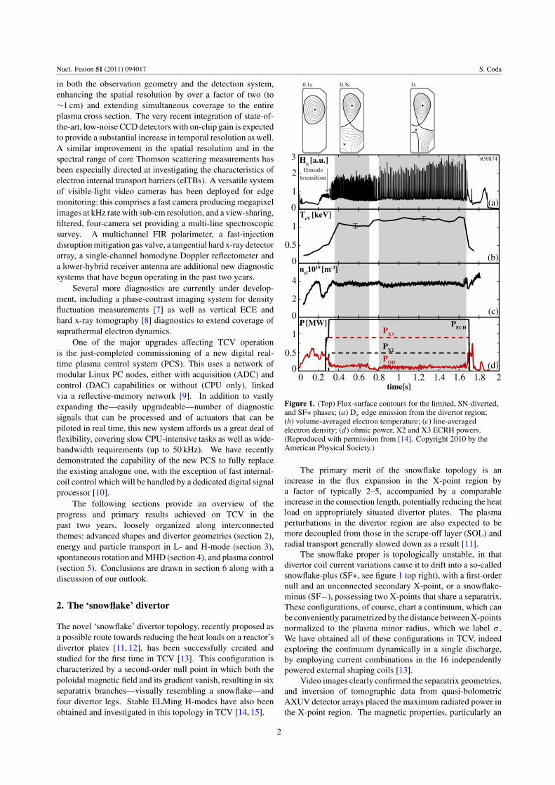
Figure 1. (Top) Flux-surface contours for the limited, SN-diverted,and SF+ phases; (a) Dα edge emission from the divertor region;(b) volume-averaged electron temperature; (c) line-averagedelectron density; (d) ohmic power, X2 and X3 ECRH powers.(Reproduced with permission from [14]. Copyright 2010 by theAmerican Physical Society.)
The primary merit of the snowflake topology is anincrease in the flux expansion in the X-point region bya factor of typically 2–5, accompanied by a comparableincrease in the connection length, potentially reducing the heatload on appropriately situated divertor plates. The plasmaperturbations in the divertor region are also expected to bemore decoupled from those in the scrape-off layer (SOL) andradial transport generally slowed down as a result [11].
The snowflake proper is topologically unstable, in thatdivertor coil current variations cause it to drift into a so-calledsnowflake-plus (SF+, see figure 1 top right), with a first-ordernull and an unconnected secondary X-point, or a snowflake-minus (SF−), possessing two X-points that share a separatrix.These configurations, of course, chart a continuum, which canbe conveniently parametrized by the distance between X-pointsnormalized to the plasma minor radius, which we label σ .We have obtained all of these configurations in TCV, indeedexploring the continuum dynamically in a single discharge,by employing current combinations in the 16 independentlypowered external shaping coils [13].
Video images clearly confirmed the separatrix geometries,and inversion of tomographic data from quasi-bolometricAXUV detector arrays placed the maximum radiated power inthe X-point region. The magnetic properties, particularly an
2
Nucl. Fusion 51 (2011) 094017 S. Coda
SNSF+
0
0.5
1
1.5 Pin [MW]
0 2 4 6 8
neV x1019[m-3]
LH powerscaling
Figure 2. Power threshold for the L–H transition versusvolume-averaged electron density for SN and SF+ configurations.The dashed line represents the 2008 international-database thresholdpower fit [16]. (Reproduced with permission from [14]. Copyright2010 by the American Physical Society.)
expected increase in magnetic shear at the edge, were verifiedthrough equilibrium reconstruction.
More recently, we have applied EC heating to SF+ plasmaswith the express purpose of investigating the possibility ofsustaining a stable H-mode. A value σ = 0.5 was chosen as acompromise between flux expansion and stable controllability.A combination of 1 MW top-injected third harmonic (X3)heating and 0.5 MW X2 heating localized at the edge (theplasma core being beyond the density cutoff layer) wasemployed to induce the L–H transition [14, 15]. A standardsingle-null (SN) and a SF+ plasma, with closely matchedshapes, were generated in the same discharge for ease ofcomparison; in both cases an ELMy H-mode was sustained(figure 1). The measured properties were verified to beindependent of the time history, i.e. the order in which the twotopologies were obtained. A modest (∼15%) enhancementin the stored energy occurs in the SF+ as opposed to theSN, which could be consistent with the effect of the residualshape difference. An important by-product of this study wasa thorough mapping of the L–H power threshold over a broaddensity range, which also, remarkably, revealed no systematicdifference between the two cases (figure 2).
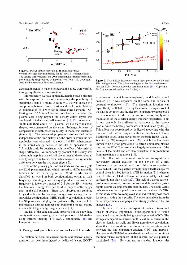
One of the primary goals of this study was to investigatethe ELM phenomenology, which proved to differ markedlybetween the two cases (figure 3). While ELMs can beclassified as type I in both configurations, owing to theirfrequency exhibiting an increasing dependence on power, thefrequency is lower by a factor of 2–3 for the SF+, whereasthe fractional energy loss per ELM is only 20–30% largerthan in the SN plasma. These two observations combineto yield a favourable average energy loss scaling for thesnowflake configuration. MHD stability calculations predictthat SF plasmas are slightly, but systematically, more stable tointermediate-toroidal-number kink-ballooning modes, mainlyas a result of higher edge magnetic shear [14].
Studies of the edge and SOL properties of the snowflakeconfiguration are ongoing, to extend previous ELM studiesusing infrared imaging [17], AXUV tomography [18] andLangmuir probes.
3. Energy and particle transport in L- and H-mode
The relation between the current profile and electron energytransport has been investigated by dedicated ‘swing ECCD’
0
0.1
0.2
0
100
200
300
400 νELM [Hz]
1.2 1.4 1.6 1.8 2 2.2Pin [MW]
0.05
0.15
∆WELM/WP
SF+ν
ELM~43 x Pin+17
SN
νELM
~184 x Pin+5
#40307#40308
Figure 3. Type-I ELM frequency versus input power for the SN andSF+ configurations. The colour coding maps the fractional energyloss per ELM. (Reproduced with permission from [14]. Copyright2010 by the American Physical Society.)
experiments, in which counter-phased, modulated co- andcounter-ECCD was deposited on the same flux surface atconstant total power [19]. The deposition location wastypically at ρ = 0.3–0.5 (ρ being the normalized square root ofthe plasma volume), and the electron temperature was observedto be modulated inside the deposition radius, implying amodulation of the electron energy transport properties. Thisin turn can only be attributed to variations in the currentprofile, since the heating power was not modulated by design.This effect was reproduced by dedicated modelling with thetransport code ASTRA coupled with the quasilinear Fokker–Plank code CQL3D, using variations on the basic Rebut–Lallia–Watkins (RLW) transport model [20], which has long beenknown to be a good predictor of electron-dominated plasmatransport in TCV. The results are largely independent of thedetails of the model and are also consistent with predictionsfrom gyrokinetic simulations [19].
The effect of the current profile on transport is aparticularly crucial question in the physics of eITBs.Systematic experimental work on fully non-inductivelysustained eITBs in the past has strongly suggested that negativecentral shear is a key factor in eITB formation [21], whereasdiscrete effects related to low-order rational safety-factor (q)surfaces do not play a role [22]. The lack of a direct current-profile measurement, however, makes model-based analysis ahighly desirable complement to such studies. The CQL3D–ASTRA
code suite was thus applied to an extensive database of eITBs.In this study ASTRA was employed as an indirect diagnostic toolfor reconstructing the q profile. The two conclusions from theearlier experimental campaign were strongly validated by thisanalysis [23].
The issue of particle transport of both electrons andions is of crucial importance to the operation of a fusionreactor and is accordingly being actively pursued in TCV. Thestrongest temperature barriers in TCV exhibit a barrier in theelectron density as well, and linear gyrokinetic calculationsshow that these conditions are found at the transition pointbetween the ion-temperature-gradient (ITG) and trapped-electron-mode (TEM) dominated regimes, where the dominantthermodiffusive component of the inward particle pinch ismaximized [24]. By contrast, in standard L-modes the
3
Nucl. Fusion 51 (2011) 094017 S. Coda
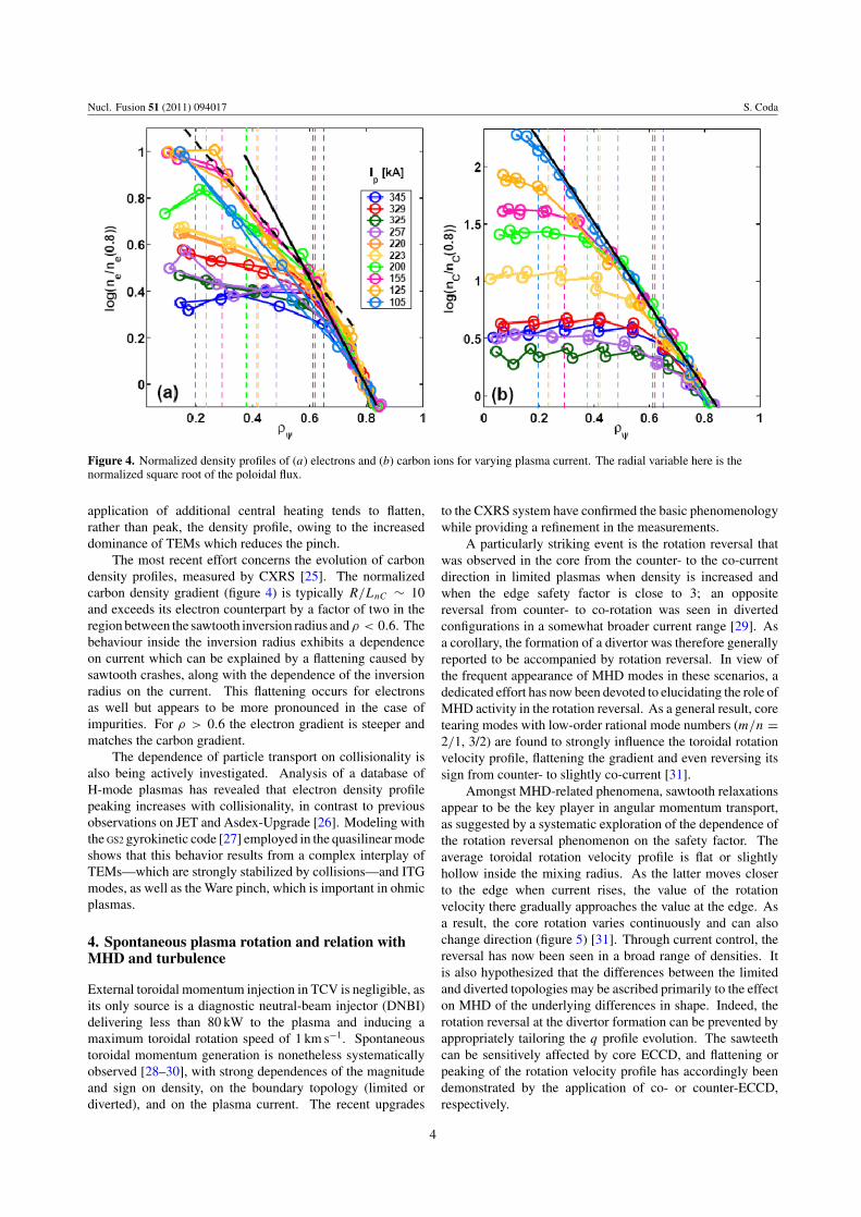
Figure 4. Normalized density profiles of (a) electrons and (b) carbon ions for varying plasma current. The radial variable here is thenormalized square root of the poloidal flux.
application of additional central heating tends to flatten,rather than peak, the density profile, owing to the increaseddominance of TEMs which reduces the pinch.
The most recent effort concerns the evolution of carbondensity profiles, measured by CXRS [25]. The normalizedcarbon density gradient (figure 4) is typically R/LnC ∼ 10and exceeds its electron counterpart by a factor of two in theregion between the sawtooth inversion radius andρ < 0.6. Thebehaviour inside the inversion radius exhibits a dependenceon current which can be explained by a flattening caused bysawtooth crashes, along with the dependence of the inversionradius on the current. This flattening occurs for electronsas well but appears to be more pronounced in the case ofimpurities. For ρ > 0.6 the electron gradient is steeper andmatches the carbon gradient.
The dependence of particle transport on collisionality isalso being actively investigated. Analysis of a database ofH-mode plasmas has revealed that electron density profilepeaking increases with collisionality, in contrast to previousobservations on JET and Asdex-Upgrade [26]. Modeling withthe GS2 gyrokinetic code [27] employed in the quasilinear modeshows that this behavior results from a complex interplay ofTEMs—which are strongly stabilized by collisions—and ITGmodes, as well as the Ware pinch, which is important in ohmicplasmas.
4. Spontaneous plasma rotation and relation withMHD and turbulence
External toroidal momentum injection in TCV is negligible, asits only source is a diagnostic neutral-beam injector (DNBI)delivering less than 80 kW to the plasma and inducing amaximum toroidal rotation speed of 1 km s−1. Spontaneoustoroidal momentum generation is nonetheless systematicallyobserved [28–30], with strong dependences of the magnitudeand sign on density, on the boundary topology (limited ordiverted), and on the plasma current. The recent upgrades
to the CXRS system have confirmed the basic phenomenologywhile providing a refinement in the measurements.
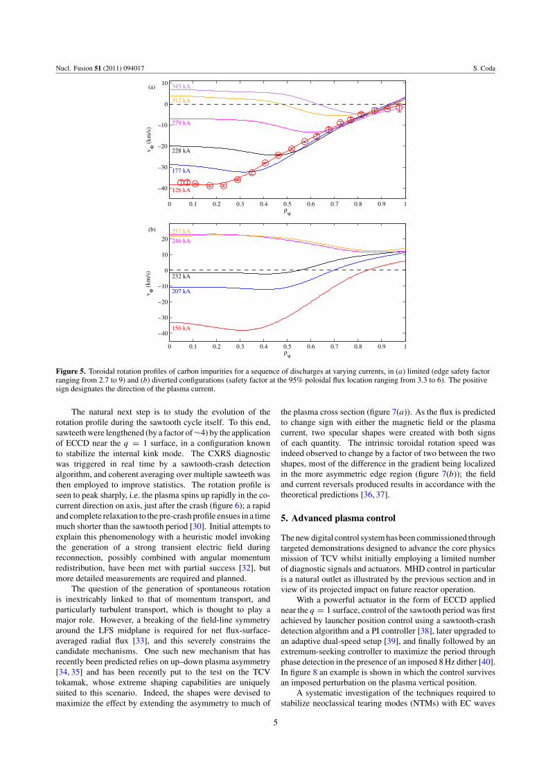
A particularly striking event is the rotation reversal thatwas observed in the core from the counter- to the co-currentdirection in limited plasmas when density is increased andwhen the edge safety factor is close to 3; an oppositereversal from counter- to co-rotation was seen in divertedconfigurations in a somewhat broader current range [29]. Asa corollary, the formation of a divertor was therefore generallyreported to be accompanied by rotation reversal. In view ofthe frequent appearance of MHD modes in these scenarios, adedicated effort has now been devoted to elucidating the role ofMHD activity in the rotation reversal. As a general result, coretearing modes with low-order rational mode numbers (m/n =2/1, 3/2) are found to strongly influence the toroidal rotationvelocity profile, flattening the gradient and even reversing itssign from counter- to slightly co-current [31].
Amongst MHD-related phenomena, sawtooth relaxationsappear to be the key player in angular momentum transport,as suggested by a systematic exploration of the dependence ofthe rotation reversal phenomenon on the safety factor. Theaverage toroidal rotation velocity profile is flat or slightlyhollow inside the mixing radius. As the latter moves closerto the edge when current rises, the value of the rotationvelocity there gradually approaches the value at the edge. Asa result, the core rotation varies continuously and can alsochange direction (figure 5) [31]. Through current control, thereversal has now been seen in a broad range of densities. Itis also hypothesized that the differences between the limitedand diverted topologies may be ascribed primarily to the effecton MHD of the underlying differences in shape. Indeed, therotation reversal at the divertor formation can be prevented byappropriately tailoring the q profile evolution. The sawteethcan be sensitively affected by core ECCD, and flattening orpeaking of the rotation velocity profile has accordingly beendemonstrated by the application of co- or counter-ECCD,respectively.
4
Nucl. Fusion 51 (2011) 094017 S. Coda
0 0.1 0.2 0.3 0.4 0.5 0.6 0.7 0.8 0.9 1
–40
–30
–20
–10
0
10
126 kA
177 kA
228 kA
279 kA
312 kA
345 kA(a)
v Φ (
km/s
)
ρψ
0 0.1 0.2 0.3 0.4 0.5 0.6 0.7 0.8 0.9 1
–40
–30
–20
–10
0
10
20
156 kA
207 kA
232 kA
246 kA
257 kA(b)
v Φ (
km/s
)
ρψ
Figure 5. Toroidal rotation profiles of carbon impurities for a sequence of discharges at varying currents, in (a) limited (edge safety factorranging from 2.7 to 9) and (b) diverted configurations (safety factor at the 95% poloidal flux location ranging from 3.3 to 6). The positivesign designates the direction of the plasma current.
The natural next step is to study the evolution of therotation profile during the sawtooth cycle itself. To this end,sawteeth were lengthened (by a factor of ∼4) by the applicationof ECCD near the q = 1 surface, in a configuration knownto stabilize the internal kink mode. The CXRS diagnosticwas triggered in real time by a sawtooth-crash detectionalgorithm, and coherent averaging over multiple sawteeth wasthen employed to improve statistics. The rotation profile isseen to peak sharply, i.e. the plasma spins up rapidly in the co-current direction on axis, just after the crash (figure 6); a rapidand complete relaxation to the pre-crash profile ensues in a timemuch shorter than the sawtooth period [30]. Initial attempts toexplain this phenomenology with a heuristic model invokingthe generation of a strong transient electric field duringreconnection, possibly combined with angular momentumredistribution, have been met with partial success [32], butmore detailed measurements are required and planned.
The question of the generation of spontaneous rotationis inextricably linked to that of momentum transport, andparticularly turbulent transport, which is thought to play amajor role. However, a breaking of the field-line symmetryaround the LFS midplane is required for net flux-surface-averaged radial flux [33], and this severely constrains thecandidate mechanisms. One such new mechanism that hasrecently been predicted relies on up–down plasma asymmetry[34, 35] and has been recently put to the test on the TCVtokamak, whose extreme shaping capabilities are uniquelysuited to this scenario. Indeed, the shapes were devised tomaximize the effect by extending the asymmetry to much of
the plasma cross section (figure 7(a)). As the flux is predictedto change sign with either the magnetic field or the plasmacurrent, two specular shapes were created with both signsof each quantity. The intrinsic toroidal rotation speed wasindeed observed to change by a factor of two between the twoshapes, most of the difference in the gradient being localizedin the more asymmetric edge region (figure 7(b)); the fieldand current reversals produced results in accordance with thetheoretical predictions [36, 37].
5. Advanced plasma control
The new digital control system has been commissioned throughtargeted demonstrations designed to advance the core physicsmission of TCV whilst initially employing a limited numberof diagnostic signals and actuators. MHD control in particularis a natural outlet as illustrated by the previous section and inview of its projected impact on future reactor operation.
With a powerful actuator in the form of ECCD appliednear the q = 1 surface, control of the sawtooth period was firstachieved by launcher position control using a sawtooth-crashdetection algorithm and a PI controller [38], later upgraded toan adaptive dual-speed setup [39], and finally followed by anextremum-seeking controller to maximize the period throughphase detection in the presence of an imposed 8 Hz dither [40].In figure 8 an example is shown in which the control survivesan imposed perturbation on the plasma vertical position.
A systematic investigation of the techniques required tostabilize neoclassical tearing modes (NTMs) with EC waves
5

Nucl. Fusion 51 (2011) 094017 S. Coda
0 0.1 0.2 0.3 0.4 0.5 0.6 0.7 0.8
–6
–4
–2
0
2crash+1 ms
+3 ms
+11 ms (pre–crash)
v Φ (
km/s
)
ρψ
Figure 6. Radial profile of toroidal rotation speed, coherently averaged over multiple sawteeth, at three times: just after the sawtooth crash,in the middle of the cycle, and after full relaxation. The latter profile is representative of the profile immediately before the crash. Thepositive sign designates the direction of the plasma current.
s+ (a) (b)s–
0 0.2 0.4 0.6 0.8 1
–30
–20
–10
0
10
20
30
ρψ
v φ (km
/s)
Figure 7. (a) Specular, up–down asymmetric flux-surface geometries; (b) toroidal rotation profiles of the carbon impurities (solid curves,measured) and bulk ions (dashed, deduced from the force balance equation assuming neoclassical poloidal rotation) for the twoconfigurations in (a) (red and blue). The dashed vertical lines indicate the sawtooth inversion radius. (Reproduced with permissionfrom [37]. Copyright 2010 IOP Publishing.)
0.4 0.6 0.8 1 1.2 1.4 1.6 1.82
3
4
5
6
au
Plasma vertical position
soft X–ray intensity Pulse 37071
0.4 0.6 0.8 1 1.2 1.4 1.6 1.8
0.18
0.19
0.2
(m)
0.4 0.6 0.8 1 1.2 1.4 1.6 1.80
5
10
ms
Sawtooth period
0.4 0.6 0.8 1 1.2 1.4 1.6 1.814
16
18
20
Time (s)
deg
rees
Launcher position
< Controller on
requested position
measured position
Figure 8. Maximization of the sawtooth period. (Reproduced with permission from [40]. Copyright 2011 IOP Publishing.)
has also begun on TCV. In particular, the tools are nowavailable to explore in detail the relative merits of modulatedversus constant ECRH and O- versus X-point deposition, andthe relative roles of heating versus current drive and directisland stabilization versus current-profile modification. InTCV, ECCD is generally also required to initially destabilizethe mode, providing additional opportunities for physics
modelling and understanding. Initial attempts have beenextremely promising, highlighting the variety of controlopportunities afforded by the multiple actuators.
A salient example is shown in figure 9, involving threegyrotrons delivering a total unmodulated 1.6 MW power tothe plasma, required to destabilize the mode. The followingcomplex succession of real-time observations and decisions
6
Nucl. Fusion 51 (2011) 094017 S. Coda
t (s)
(kH
z)
12
3 45
0
5
10
15
20
25
30
Central SXR [au]
0
250
500
750
1000
EC
H p
ower
(kW
)
P2
P4+P
5ρ
dep,2
ρdep,4–5
#40418
0
0.2
0.4
0.6
0.8
ρ ψ
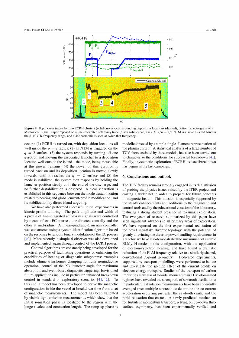
Figure 9. Top: power traces for two ECRH clusters (solid curves), corresponding deposition locations (dashed); bottom: spectrogram of aMirnov coil signal, superimposed on a line-integrated soft x-ray trace (black solid curve, a.u.), A m/n = 2/1 NTM is visible as a red band inthe 6–10 kHz frequency range, and a 4/2 harmonic is seen at twice that frequency.
occurs: (1) ECRH is turned on, with deposition locations allwell inside the q = 2 radius; (2) an NTM is triggered on theq = 2 surface; (3) the system responds by turning off onegyrotron and moving the associated launcher to a depositionlocation well outside the island—the mode, being metastableat this power, remains; (4) the power on this gyrotron isturned back on and its deposition location is moved slowlyinwards, until it reaches the q = 2 surface and (5) themode is stabilized; the system then responds by holding thelauncher position steady until the end of the discharge, andno further destabilization is observed. A clear separation isestablished in this sequence between the mode destabilizationrelated to heating and global current-profile modification, andits stabilization by direct island targeting.
We have also performed successful initial experiments inkinetic profile tailoring. The peak amplitude and width ofa profile of line-integrated soft-x-ray signals were controlledby means of two EC sources, one directed centrally and theother at mid-radius. A linear-quadratic-Gaussian controllerwas constructed using a system-identification algorithm basedon the response to random binary modulation of the EC powers[40]. More recently, a simple β observer was also developedand implemented, again through control of the ECRH power.
Control algorithms are constantly being developed for thepractical purpose of facilitating operations or enhancing thecapabilities of heating or diagnostic subsystems: examplesinclude ohmic transformer clamping for fully noninductiveoperation, control of the X3 launcher angle for maximumabsorption, and event-based diagnostic triggering. Envisionedfuture applications include in particular enhanced breakdowncontrol in standard or exploratory scenarios [41, 42]. Tothis end, a model has been developed to derive the magneticconfiguration inside the vessel at breakdown time from a setof magnetic measurements. The model has been validatedby visible-light emission measurements, which show that theinitial ionization phase is localized to the region with thelongest calculated connection length. The ramp-up phase is
modelled instead by a simple single-filament representation ofthe plasma current. A statistical analysis of a large number ofTCV shots, assisted by these models, has also been carried outto characterize the conditions for successful breakdown [41].Finally, a systematic exploration of ECRH-assisted breakdownhas begun in the last campaign.
6. Conclusions and outlook
The TCV facility remains strongly engaged in its dual missionof probing the physics issues raised by the ITER project andcasting a wider net in order to prepare for future conceptsin magnetic fusion. This mission is especially supported bythe steady enhancements and additions to the diagnostic andcontrol tools and by the educational vocation of the laboratory,featuring a strong student presence in tokamak exploitation.The two years of research summarized by this paper haveseen significant advances in all primary areas of exploration.We have reported on the first experimental realization ofthe novel snowflake divertor topology, with the potential ofgreatly alleviating the divertor power handling requirements ina reactor; we have also demonstrated the sustainment of a stableELMy H-mode in this configuration, with the applicationof electron-cyclotron heating, and have found a dramaticreduction of the ELM frequency relative to a similarly shaped,conventional X-point geometry. Dedicated experiments,supported by transport modelling, were performed to isolateand investigate the specific effect of the current profile onelectron energy transport. Studies of the transport of carbonimpurities as well as of toroidal momentum in TEM-dominatedregimes have revealed the strong role of sawtooth oscillations;in particular, fast rotation measurements have been coherentlyaveraged over multiple sawteeth to determine the co-currentacceleration occurring just after the sawtooth crash, and therapid relaxation that ensues. A newly predicted mechanismfor turbulent momentum transport, relying on up–down flux-surface asymmetry, has been experimentally verified and
7
Nucl. Fusion 51 (2011) 094017 S. Coda
documented for the first time. Finally, we have reported ona budding and rapidly expanding program of nonlinear digitalcontrol of a uniquely flexible and versatile magnetic-coil andelectron-cyclotron heating complement.
Our future outlook envisions a greater diversificationthrough a series of major upgrades, which include neutral-beam heating (up to 3 MW) [43], 3 MW additional X3 power,and a complete refurbishment of the low-field-side plasma-facing components for improved power handling. This willallow the extension of our shaping investigations to high-power scenarios, in particular to study H–mode physics innegative triangularity configurations. A set of in-vessel saddlecoils to generate resonant magnetic perturbations for error-field correction and ELM control would also be installed atthis time [44]. These upgrades are proposed to be phased induring the next six years and thus to be fully implemented wellbefore the start of ITER operation.
Acknowledgment
This work was supported in part by the Swiss National ScienceFoundation.
© Euratom 2011.
References
[1] Hofmann F. et al 1994 Plasma Phys. Control. Fusion 36 B277[2] ITER Technical Basis 2002 ITER EDA Documentation Series
No 24 (Vienna: IAEA)[3] Pamela J., Becoulet A., Borba D., Boutard J.-L., Horton L. and
Maisonnier D. 2009 Fusion Eng. Des. 84 194[4] Goodman T.P. and the TCV Team 2008 Nucl. Fusion
48 054011[5] Lister J.B. et al 1997 Fusion Sci. Technol. 32 321[6] Fasoli A. for the TCV Team 2009 Nucl. Fusion 49 104005[7] Marinoni A., Coda S., Chavan R. and Pochon G. 2006 Rev.
Sci. Instrum. 77 10E929[8] Gnesin S., Coda S., Decker J. and Peysson Y. 2008 Rev. Sci.
Instrum. 79 10F504[9] Paley J.I., Coda S., Duval B., Felici F., Moret J.-M. and the
TCV Team 2010 Architecture and commissioning of theTCV distributed plasma feedback control system Proc. 17thIEEE Real Time Conf. (Lisboa, Portugal, 24–28 May 2010)
[10] Cruz N., Moret J.-M., Coda S., Paley J.I., Duval B.P.,Rodrigues A.P., Piras F., Felici F., Correia C.M.B.A. andVarandas C.A.F. 2010 Using APCS for Plasma VerticalControl at TCV Proc. 17th IEEE Real Time Conf. (Lisboa,Portugal, 24–28 May 2010) IEEE Trans. Nucl. Sci.submitted
[11] Ryutov D.D. 2007 Phys. Plasmas 14 064502[12] Ryutov D.D., Cohen R.H., Rognlien T.D. and Umansky M.V.
2008 Phys. Plasmas 15 092501[13] Piras F. et al 2009 Plasma Phys. Control. Fusion 51 055009[14] Piras F., Coda S., Duval B.P., Labit B., Marki J.,
Medvedev S.Yu., Moret J.-M., Pitzschke A., Sauter O. andTCV team 2010 Phys. Rev. Lett. 105 155003
[15] Piras F., Coda S., Duval B.P., Labit B., Marki J.,Medvedev S.Yu., Moret J.-M., Pitzschke A., Sauter O.and TCV team 2010 Plasma Phys. Control. Fusion52 124010
[16] Martin Y.R., Takizuka T. and ITPA CDBM H-mode ThresholdDatabase Working Group 2008 J. Phys.: Conf. Ser.123 012033
[17] Marki J., Pitts R.A., Horacek J., Tskhakaya D. and The TCVTeam 2009 J. Nucl. Mater. 390–391 801
[18] Veres G., Pitts R.A., Bencze A., Marki J., Tal B., Tye R. andTCV Team 2009 J. Nucl. Mater. 390–391 835
[19] Zucca C., Sauter O., Alberti S., Cirant S., Goodman T.P. andTurri G. 2009 Plasma Phys. Control. Fusion 51 125009
[20] Rebut P.H., Lallia P.P. and Watkins M.L. 1988 Proc. 12th. Int.Conf. on Plasma Physics and Controlled Nuclear FusionResearch 1988 (Nice, France, 1988) vol 2 (Vienna: IAEA)p 191
[21] Henderson M.A., Camenen Y., Coda S., Goodman T.P.,Nikkola P., Pochelon A., Sauter O. and TCV Team 2004Phys. Rev. Lett. 93 215001
[22] Goodman T.P. et al 2005 Plasma Phys. Control. Fusion47 B107
[23] Zucca C., Sauter O., Asp E., Coda S., Fable E., Goodman T.P.and Henderson M.A. 2009 Plasma Phys. Control. Fusion51 015002
[24] Fable E., Angioni C. and Sauter O. 2010 Plasma Phys.Control. Fusion 52 015007
[25] Martin Y. et al 2010 23rd IAEA Fusion Energy Conf. (Daejeon,Korea, 2010) (Vienna: IAEA) CD-ROM File EXC/P8-13http://www-pub.iaea.org/MTCD/Meetings/cn180 papers.asp
[26] Wagner D., Fable E., Pitzschke A., Sauter O., Weisen H. andthe TCV team 2010 37th EPS Conf. (Dublin, Ireland, 2010)vol 34A P-5.125 (ECA)http://ocs.ciemat.es/EPS2010PAP/html/index.html
[27] Kotschenreuther M., Rewoldt G. and Tang W.M. 1995Comput. Phys. Commun. 88 128
[28] Bortolon A., Duval B.P., Pochelon A. and Scarabosio A. 2006Phys. Rev. Lett. 97 235003
[29] Duval B.P., Bortolon A., Karpushov A., Pitts R.A.,Pochelon A., Sauter O., Scarabosio A., Turri G. and theTCV Team 2008 Phys. Plasmas 15 056113
[30] Duval B.P., Bortolon A., Federspiel L., Felici F., Furno I.,Karpushov A., Paley J., Piras F. and the TCV team 201023rd IAEA Fusion Energy Conf. (Daejeon, Korea, 2010)(Vienna: IAEA) CD-ROM File EXS/P4-01http://www-pub.iaea.org/MTCD/Meetings/cn180 papers.asp
[31] Sauter O., Duval B.P., Federspiel L., Felici F., Goodman T.P.,Karpushov A., Puddu S., Rossel J. and the TCV team 201023rd IAEA Fusion Energy Conf. (Daejeon, Korea, 2010)(Vienna: IAEA) CD-ROM File EXS/P2-17http://www-pub.iaea.org/MTCD/Meetings/cn180 papers.asp
[32] Bortolon A 2009 Plasma rotation and momentum transportstudies in the TCV tokamak based on charge exchangespectroscopy measurements PhD Thesis EPFL no 4569http://library.epfl.ch/theses/?nr=4569
[33] Peeters A.G. and Angioni C. 2005 Phys. Plasmas 12 072515[34] Camenen Y., Peeters A.G., Angioni C., Casson F.J.,
Hornsby W.A., Snodin A.P. and Strintzi D. 2009 Phys. Rev.Lett. 102 125001
[35] Camenen Y., Peeters A.G., Angioni C., Casson F.J.,Hornsby W.A., Snodin A.P. and Strintzi D. 2009 Phys.Plasmas 16 062501
[36] Camenen Y. et al 2010 Phys. Rev. Lett. 105 135003[37] Camenen Y. et al 2010 Plasma Phys. Control. Fusion
52 124037[38] Paley J.I. et al 2009 Nucl. Fusion 49 085017[39] Paley J.I., Felici F., Coda S., Goodman T.P., Piras F. and the
TCV Team 2009 Plasma Phys. Control. Fusion 51 055010[40] Paley J.I., Felici F., Coda S., Goodman T.P. and the TCV Team
2009 Plasma Phys. Control. Fusion 51 124041[41] Piras F., Goodman T., Moret J.-M., Bencze A., Duval B.P.,
Rossel J.X., Wagner D. and the TCV team 2010 37th EPSConf. (Dublin, Ireland, 2010) vol 34A (ECA) P-2.186http://ocs.ciemat.es/EPS2010PAP/html/index.html
[42] Piras F., Moret J.-M., Rossel J.X. and the TCV team 2010Fusion Eng. Des. 85 739
[43] Karpushov A.N., Duval B.P., Chavan R., Fable E.,Mayor J.-M., Sauter O. and Weisen H. 2010 A scopingstudy of the application of neutral beam heating on the TCVtokamak Proc. 26th Symp. on Fusion Technol. (Porto,Portugal, 2010) P1-054 Fusion Eng. Des. at press
[44] Rossel J.X., Moret J.-M., Martin Y. and the TCV team 2010Plasma Phys. Control. Fusion 52 035006
8