
Programmable Point-source Digital In-line Holography Using
20
7 Programmable Point-source Digital In-line Holography Using Digital Micro-mirror Devices Adekunle A. Adeyemi and Thomas E. Darcie University of Victoria, Victoria BC Canada 1. Introduction Digital holographic imaging techniques allow fast retrieval of three-dimensional (3-D) amplitude and phase information of an object volume through numerical reconstruction of a two-dimensional (2-D) hologram. Digital holography consists of digital sampling of a hologram on an array of charged-coupled device detectors (CCD), and digital reconstruction of the object field through a numerical algorithm [Sch94, SJ02, Yar03]. The recording process encodes 3-D information of an object into the form of interference fringes on a two- dimensional recording screen. These fringes usually contain high spatial frequencies that represent the mixing between the scattered object field and coherent reference wave. A reconstruction process is performed on the recorded hologram to recover the object wave. This numerical acquisition method eliminates the need for any chemical processing of the hologram and mechanical refocusing of the reconstructed image that is commonly required in the traditional holographic imaging system [CMD99, DJL99, SPISSSW97]. This process has opened new frontiers in digital holography with emerging applications in research and industry [Kre05, SJ05]. Typically, common digital holography recording set-ups include off-axis and in-line configurations [SJ94]. Digital in-line holography (DIH) represents the simplest realization of the digital holography (DH), allowing for rapid acquisition of hologram images without the use of lenses. Recently, DIH with a spherical reference field has emerged as an attractive tool in 3D imaging of biological objects and micro-spheres without the use of lenses [GXJKJK06a, RGMNS06, XJMK02a, XJMK02b]. Basically, the configuration consists of a coherent light source – a pinhole – to generate a spherical reference field. An array of charge-coupled device detectors (CCD) provides digital sampling of a hologram. However, the characteristics and parameters of these components can affect the overall performance of the system. Among factors that limit the performance of a digital in-line holographic microscope (DIHM) are the size and spatial location of the pinhole used. These affect the resolution, obtainable field of view (FOV) and object illumination angle (which determines the projection view in the reconstructed image volume.) In [GPO08], the effect of the pinhole size on the spatial coherence of the reference beam in a DIHM system was studied. The results showed that a reduction in the coherence of the light, due to increase in the size of the pinhole used, leads to broadening of the impulse response of the system. Consequently, this limits the obtainable resolution in the reconstructed image. Other resolution-limiting www.intechopen.com
Transcript of Programmable Point-source Digital In-line Holography Using

7
Programmable Point-source Digital In-line Holography Using Digital Micro-mirror Devices
Adekunle A. Adeyemi and Thomas E. Darcie University of Victoria, Victoria BC
Canada
1. Introduction
Digital holographic imaging techniques allow fast retrieval of three-dimensional (3-D) amplitude and phase information of an object volume through numerical reconstruction of a two-dimensional (2-D) hologram. Digital holography consists of digital sampling of a hologram on an array of charged-coupled device detectors (CCD), and digital reconstruction of the object field through a numerical algorithm [Sch94, SJ02, Yar03]. The recording process encodes 3-D information of an object into the form of interference fringes on a two-dimensional recording screen. These fringes usually contain high spatial frequencies that represent the mixing between the scattered object field and coherent reference wave. A reconstruction process is performed on the recorded hologram to recover the object wave. This numerical acquisition method eliminates the need for any chemical processing of the hologram and mechanical refocusing of the reconstructed image that is commonly required in the traditional holographic imaging system [CMD99, DJL99, SPISSSW97]. This process has opened new frontiers in digital holography with emerging applications in research and industry [Kre05, SJ05]. Typically, common digital holography recording set-ups include off-axis and in-line configurations [SJ94]. Digital in-line holography (DIH) represents the simplest realization of the digital holography (DH), allowing for rapid acquisition of hologram images without the use of lenses. Recently, DIH with a spherical reference field has emerged as an attractive tool in 3D imaging of biological objects and micro-spheres without the use of lenses [GXJKJK06a, RGMNS06, XJMK02a, XJMK02b]. Basically, the configuration consists of a coherent light source – a pinhole – to generate a spherical reference field. An array of charge-coupled device detectors (CCD) provides digital sampling of a hologram. However, the characteristics and parameters of these components can affect the overall performance of the system. Among factors that limit the performance of a digital in-line holographic microscope (DIHM) are the size and spatial location of the pinhole used. These affect the resolution, obtainable field of view (FOV) and object illumination angle (which determines the projection view in the reconstructed image volume.) In [GPO08], the effect of the pinhole size on the spatial coherence of the reference beam in a DIHM system was studied. The results showed that a reduction in the coherence of the light, due to increase in the size of the pinhole used, leads to broadening of the impulse response of the system. Consequently, this limits the obtainable resolution in the reconstructed image. Other resolution-limiting
www.intechopen.com

Holography, Research and Technologies
156
factors in DIHM include the size and position of the CCD, pixel density in the hologram, location of the object between the pinhole and CCD, and wavelength of the reference wave [GXJKJK06b, JGXJK06, RPP04, KJMX01]. Another limiting effect of the size of pinhole used is the restriction of the field of view (area captured) in the reconstructed image, especially when imaging an object that extends over an area of larger dimension compared to the numerical aperture of the system. In [GXJKJK06a, GXJKJK06b], it has been shown that the illuminated area in the object plane, as well as the FOV depends on the pinhole size. Provided the CCD is large enough to capture sufficient interference fringes, the higher spatial coherence obtained from smaller pinhole leads to an increase in the illuminated area in the object plane and hence wider FOV. For three-dimensional imaging, the spatial location of the pinhole determines the object illumination angle and projection view in the reconstructed image. Thus the use of static pinhole in the current DIHM configuration limits the object illumination angle to that provided by the pinhole location. Consequently, this also restricts the angular directional view of a reconstructed image volume to the position of the pinhole. These projections can potentially be used to extract depth information between different planes through the image volume. The aim of this chapter is to describe one possible way to address key limitations in the present configuration of DIHM, especially in recording different projections to extract depth information by point-source translation. This involves recording of holograms at different spatial locations of the point-source. The numerically reconstructed images of these holograms can be either combined into a single image with a wider FOV or used to extract depth information in the image volume. Among other techniques of achieving a scanning point source, a DIHM system that utilized digital micro-mirror devices (DMD) to program the source of the spherical reference field (point source) has been proposed [AD09a]. The DMD is a silicon-based reflective spatial light modulator that consists of more than a million individually addressable and switchable aluminum mirror pixels on a complementary metal oxide semiconductor (CMOS) static random access memory. Early application of the DMD is in projection systems but several emerging applications have evolved and these include confocal microscopy, high dynamic range imaging, 3D metrology and holography [ABD09, BPS03, DM99]. Applications of DMD in off-axis digital holographic recording and reconstruction have been demonstrated [DDS03, KN98]. In DIHM with a programmed point-source, the scanning of the spatial location of the point source was achieved by using the DMD as the primary source of the spherical reference field that illuminates the object. Thus, translation of the addressable ON-state mirror pixel on the DMD plane leads to scanning of the point source with respect to the object position. In addition to programming the point-source, another advantage of this system is the flexibility in reconfiguring the point-source size by simply varying the number of the ON-state DMD pixels. The application of the system to enhancement of the limited FOV in DIHM has been reported [AD09a]. The results obtained through numerical reconstruction of the recorded-translated holograms of Latex micro-spheres deposited on a microscope slide show the possibility of expanding the field of view by 263%. Recently [AD09b], we have extended the application of the system, using microspheres deposited on both side of microscope slide, to record different projections of holograms. Early published results show the possibility of recording different projections of the hologram. In this chapter, we provide an in-depth analysis on the application of the programmable point-source DIHM to extract depth information using projections of the reconstructed
www.intechopen.com

Programmable Point-source Digital In-line Holography Using Digital Micro-mirror Devices
157
image volume. A relationship between the change in illumination angle and the corresponding depth separation using a point source on two parallel planes is established. A review on the expansion of the field of view in DIHM is provided as a complete analysis and demonstration of the capability of the programmable point-source DIHM. We begin with a detailed description of the DMD-based programmable point-source DIHM system and a review of the hologram recording and reconstruction techniques.
2. DMD-based programmable point-source DIHM system
The DMD plane axis and schematic diagram of a spherical reference field digital in-line
holographic microscope with a programmable point source are shown in Fig. 1 (a) and (b),
respectively. A collimated laser beam (0.38 watts, 532nm wavelength and 3mm in diameter)
illuminates the Texas Instruments DMD chip with 1024 x 768 pixel elements; each mirror is
13.68 µm x 13.68 µm square in size, with 14.68 µm pitch.
We mounted the DMD chip at 45 degrees to the surface of the optical table with illumination
beam directed at about 20 degrees to the chip normal so that light from the ON-state mirror
element is reflected perpendicularly to the chip. One of the main challenges we encountered
during illumination of DMD array with coherent light was the appearance of interference
fringes when a mirror element is switched ON. This was caused by the interference between
the background diffraction light (resulting from the spreading of the illumination beam by
the 2-D periodic pattern of the square elements on the DMD array) and light reflected from
the ON-state mirror element. We noted the background diffracted orders from the array are
fixed in space and any changes to the states of the mirror elements only redistribute the
intensity of light among the orders.
Fig. 1. Schematic diagram of the programmable pinhole DIH
To reduce this fringe effect, we employ a simple but effective method to spatially separate
the ON-state reflected light from the background. This is achieved by locating lens L1
(f1=150mm and 25mm diameter) at a focal distance from the DMD elements such that the
diffracted-collimated background light is focused at a certain distance behind the lens and
ON-state reflected light is collimated behind the lens simultaneously, as shown in Fig. 1 (b).
An ink drop on a cover slide (perpendicular to the beam path and positioned at back focal
plane of L1) is used to stop the focused background diffracted light that falls directly within
┟ ξ
Po
P4
P1
P2
P3 Cover slide with ink
CCD
Incident beam
f1f2
Light from ON-state element
DMD
Specimen
L1 L2 d
D
Background light S
(FP1)
(FP2)
(b)(a)
www.intechopen.com

Holography, Research and Technologies
158
the field of view, while the other background diffracted orders are blocked with an iris
located behind lens L1. In order to completely block this focused background diffracted
light, the diameter of the ink spot is made slightly larger than the focused spot. The light
from the ON-state element, transmitted through the cover slide, is brought into focus by
lens L2 (f2=25mm and 25mm diameter). This focused spot represents the point source in the
system.
A typical diffraction pattern from 10x10 ON-state mirror elements (without the ink spot)
captured at approximately 10mm from the focal plane is shown in Fig. 2. The figure also
reveals the appearance of the interference fringes resulting from the superposition of the
background diffracted light and ON-state reflected light. As the number of the “ON”
elements is reduced, the size of the central main lobe (zero order) is increased. Hence, for a
single DMD element, the size of the central lobe is increased beyond the diameter of the iris
opening so that only light from this lobe is admitted into the aperture of L1.
Fig. 2. Diffraction pattern from 10x10 DMD elements
The size of the point source is determined by the number of ON-state DMD elements and
the demagnification between lens L1 and L2 (f1/f2). Typically, the minimum achievable size
of the point source in this configuration for a single element in the “ON” state and
demagnification factor of 6 (150/25) is approximately 2.2 µm. However, smaller point-
source size can be obtained by using more powerful lens combination with high NA. The
size of the point source can be reconfigured by simply varying the number of the elements
in the “ON” state. Light from the focused spot propagates spherically towards the object
plane (located at distance S from the focal plane) and generates an object scattered field that
interferes with the undiffracted spherical reference field at the CCD plane (located at
distance d from the object). The CCD (Qimaging Retiga 2000R) is set to a resolution of 1200 x
1200 pixels with 7.4 µm x 7.4 µm pixel size.
3. Hologram recording and reconstruction
3.1 Recording
To record holograms, one DMD mirror element is switched to ON-state at position
Po o o(ξ ,┟ ) and translated to different position PN o ξ ξ o ┟ ┟(ξ n T ,┟ n T )± ± , where ξT , ξn
and ┟T , ┟n denotes the number of switching step and step size respectively, on ξ − and
η − axis of the DMD plane. Consequently, this process moves the focused point source to a
different lateral position to create translated holograms of the object. The holograms
captured for each DMD position represent the intensity of the interference field.
www.intechopen.com

Programmable Point-source Digital In-line Holography Using Digital Micro-mirror Devices
159
If the complex spherical reference and object field at the CCD plane be represented by
R(x,y) and O(x,y) respectively, such that
R
o
iφ (x,y)R
iφ (x,y)o
R(x,y) A (x,y)exp , and
O(x, y) A (x,y)exp
== (1)
where RA (x,y) and oA (x,y) are real amplitudes and Rφ (x,y) and oφ (x,y) represent the
phase of reference and object waves respectively. The mixing of the two fields at the CCD
plane generates an interference field H(x,y) such that,
( )R o Riφ (x,y) i(φ (x,y) φ (x,y))R o
H(x,y) R(x,y) O(x,y)
exp A A exp .−= += + (2)
The intensity pattern W(x,y) measured by the CCD is
o R
2
i(φ (x,y) φ (x,y))2 2R o R o
W(x,y) H(x,y)
Re A A 2A A exp .−=
⎡ ⎤= + +⎣ ⎦ (3)
In addition to the recorded holograms, background light intensity is captured for each
position of the point source. This is achieved by translating the object out of the hologram
field of view such that only the spherical reference light transmitted through the clear part
of the microscope glass slide is captured.
3.2 Numerical reconstruction
To reduce the effect of the background noise in the reconstructed image, the background
intensity image of the reference beam (captured at every position of the point source) is
subtracted from the corresponding hologram to generate a contrast hologram. The scattered
wave U(X,Y,d), which carries the information of the object, is recovered from the contrast
holograms using Fresnel-Kirchhoff diffraction integral with the well-known convolution
approach [5].
( ) ˆU X,Y,d W(x,y)G(X x,Y y,d)dxdy .∞ ∞−∞ −∞= − −∫ ∫ (4)
In equation (4), ˆG(X x,Y y,d)− − is the impulse response function of the system with
distance d̂ representing a multiplication between distance d and fringe magnification Dm
s= that results from using the spherical reference field. The term W(x,y) represents
the contrast hologram. Using equation (4), the Fourier transforms of both W(x,y) and ˆG(X,Y,d) are multiplied and an inverse Fourier transform applied to the product to obtain
the object wave ( )U X,Y,d . Depth reconstruction can be obtained by reconstructing ( )U X,Y,d on different planes. The intensity I(X,Y) of the reconstructed wave is calculated
as
2
I(X,Y) U(X,Y)= . (5)
www.intechopen.com

Holography, Research and Technologies
160
4. Analysis
4.1 Translations in the DMD and hologram plane
Control of the DMD elements is achieved through control software that communicates directly with the chip via a USB port. This allowed translation of individual elements over a specified switching interval, equivalent to some number of elements. Consequently, the translation of the ON-state DMD elements generates two main effects in the object illumination. First, it leads to shifting of the point source (spherical reference beam) with respect to the object position, since the DMD serve as the primary source of light. Hence, a translated hologram of the object is generated with the interference fringes moving in the opposite direction of the element switching. Second, for objects with some depth features, the translation also changes the illumination angle of the depth features thereby encoding information about different projections through the object volume in the translated hologram.
If dmdT and holoT represents the linear translations distance in the ξ − ┟ plane of the DMD and hologram plane respectively, the relationship can be expressed as follows.
dmdL
holo
TM
T= , (6)
where 1L
2
fM
f= is the magnification between lens L1 and L2. Thus for a given translation on
the DMD plane, the corresponding translation distance in the hologram plane is determined
by the magnification ( LM ) in the system. A higher translation distance in the hologram
plane can be obtained by decreasing LM .
4.2 Focused spot size
For light admitted by L1 from the ON-state DMD elements, the combination of lens L1 and L2 acts as a de-magnifier depending on the ratio between f1 and f2. This process recreates the image of the ON-state DMD elements at the focal plane of L2 (FP1). Thus the focused spot size o(W ) is determined by the achievable de-magnification d(M ) between lens L1 and L2 such that
o dmd dW Δ M= (7)
where L
1d MM = and dmdΔ denotes the DMD mirror element size. For the configuration
shown in Fig. 1, the dimension of the ON-state DMD elements is reduced by a factor of 6
(i.e. dM 6= ). Thus, the minimum focal spot is 2.2 µm and this corresponds to a single
element (13.68um x 13.68um) in On-state (i.e. in position P1).
4.3 Field of view and reconstructed object magnification
Factors that limit the achievable resolution in DIHM have been treated extensively with developed criteria for achieving lateral as well as depth resolution [GXJKJK06a, GXJKJK06b, JGXJK06]. The FOV in DIHM is defined as the area in the object plane magnified by the incident spherical reference field and captured in the reconstructed hologram. Since the resolution and effective number of interference fringes in the recorded hologram are limited significantly by the size and position of the CCD, it is difficult to achieve the desired
www.intechopen.com

Programmable Point-source Digital In-line Holography Using Digital Micro-mirror Devices
161
resolution (with adequate magnification) and wide field of view simultaneously in the reconstructed images. This is applicable to imaging an object that extends over an area of larger dimension compared to the numerical aperture of the system. Increasing the object area (FOV) captured in a hologram, for a given resolution, leads to reduction in the magnification (M) of the reconstructed object features.
(b)
mµ 361 mµ 301
137 µm 51.7 µm
(d)
(a)
(c)
Fig. 3. Bright-field image and reconstructions of 9-µm spheres deposited on a microscope glass slide: (a) Image obtained from compound bright-field microscope. (b) - (d) Reconstructed images at distance S = 1.875 mm, 4.7 mm and 7.3 mm from the point source respectively. Green laser; 2.2-µm point source; D = 4.3 cm; NA = 0.103.
To illustrate this, Fig 3(a)-(d) shows the holographic reconstructed images of 9 µm spheres (D=4.3 cm) at distances S = 1.875 mm, 4.7 mm and 7.3 mm from the point source respectively. The corresponding estimated FOV in Fig. 3(b)-(d) are approximately 0.3 mm, 0.53mm and 0.95 mm respectively. From the images, we observe a reduction in the magnification of the objects as the FOV is increased i.e. as more object areas are captured in the recorded hologram. Thus, for a given resolution, determined by the DIHM configuration parameters, the obtained magnification in DIHM is compromised as the FOV in the reconstructed images increases. However, since one of the primary tasks of any microscope is to produce a magnified and resolved image of a given specimen with high contrast, a system that improves the range of the FOV for a given resolution and magnification at certain CCD position is necessary.
4.4 Depth information extraction
The spatial location of the point source in the programmable point-source DIHM, with respect to the object position, determines the object illumination angle. For a 2-D object
www.intechopen.com

Holography, Research and Technologies
162
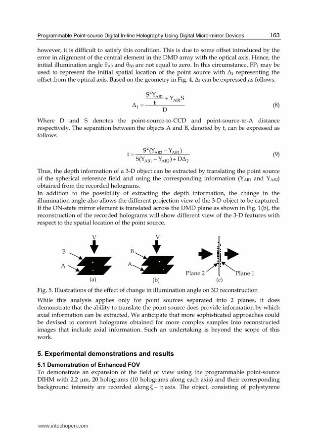
occupying a lateral plane and located at some distance from the point source (Fig. 1(b)), a change in the position of the point source leads to lateral translation of the object in the reconstruction plane. However, for 3-D object with features occupying different planes in depth, the translation of the point source leads to a change in the illumination angle. Figure 4 shows an illustration with two point objects A and B separated by axial distance t and lying on optical axis G0G (perpendicular to the hologram plane).
CCD
Fig. 4. Schematic illustration of change in object illumination angle resulting from point-source translation
When these objects are illuminated from point source located at G0, the illumination angle (┠A0 and ┠B0, not shown in the illustration) corresponding to these objects are equal to zero. Consequently, the corresponding hologram of these objects will superimpose with the center of the interference pattern at G. The reconstructed image of the objects (when the reconstructed planes are combined in depth) will overlap when viewed from the direction indicated by arrow V (from the top of the aligned images) as shown in Fig. 5(a). However, shifting the point source from G0 to position FP1 through distance Δ1 changes the illumination angle such that ┠B1 < ┠A1. The difference between these angles i.e. (┠A1 - ┠B1) transform to a separation (YAB1 = A1 – B1) between the center of hologram of A and B on the CCD plane. An illustration of the separation between the reconstructed image of A and B is shown in Fig. 5(b). Similarly, when the point source is translated from FP1 to FP2 through a distance Δ2, the illumination angles ┠A1 and ┠B1 are increased to ┠A2 and ┠B2 respectively. This consequently leads to an increment in the separation between the holograms of A and B such that YAB2 > YAB1. The illustration in Fig. 4 is based on an initial condition which assumes the objects (A and B) and point source are perfectly located on the optical axis G0G (i.e. ┠A0 = ┠B0 = 0). In practice,
www.intechopen.com
Programmable Point-source Digital In-line Holography Using Digital Micro-mirror Devices
163
however, it is difficult to satisfy this condition. This is due to some offset introduced by the error in alignment of the central element in the DMD array with the optical axis. Hence, the initial illumination angle ┠A0 and ┠B0 are not equal to zero. In this circumstance, FP1 may be used to represent the initial spatial location of the point source with Δ1 representing the offset from the optical axis. Based on the geometry in Fig. 4, Δ1 can be expressed as follows.
2AB1
AB1
1
S YY S
tΔD
+= (8)
Where D and S denotes the point-source-to-CCD and point-source-to-A distance respectively. The separation between the objects A and B, denoted by t, can be expressed as follows.
2
AB2 AB1
AB1 AB2 2
S (Y Y )t
S(Y Y ) DΔ−= − + (9)
Thus, the depth information of a 3-D object can be extracted by translating the point source of the spherical reference field and using the corresponding information (YAB1 and YAB2) obtained from the recorded holograms. In addition to the possibility of extracting the depth information, the change in the illumination angle also allows the different projection view of the 3-D object to be captured. If the ON-state mirror element is translated across the DMD plane as shown in Fig. 1(b), the reconstruction of the recorded holograms will show different view of the 3-D features with respect to the spatial location of the point source.
B
A
(a)
V
A
B
(b)
V
Plane 2 Plane 1 (c)
Fig. 5. Illustrations of the effect of change in illumination angle on 3D reconstruction
While this analysis applies only for point sources separated into 2 planes, it does demonstrate that the ability to translate the point source does provide information by which axial information can be extracted. We anticipate that more sophisticated approaches could be devised to convert holograms obtained for more complex samples into reconstructed images that include axial information. Such an undertaking is beyond the scope of this work.
5. Experimental demonstrations and results
5.1 Demonstration of Enhanced FOV
To demonstrate an expansion of the field of view using the programmable point-source DIHM with 2.2 µm, 20 holograms (10 holograms along each axis) and their corresponding background intensity are recorded along ξ − ┟ axis. The object, consisting of polystyrene
www.intechopen.com
Holography, Research and Technologies
164
microspheres (9um diameter) deposited on a microscope glass slide, and CCD are located at a distance S = 1.875 mm and D = 43 mm from the point source, respectively. This corresponds to a magnification m = 23. We reconstructed all the holograms captured to be combined to generate a single reconstructed image with a wider field of view.
To summarize the hologram recording process described in Section 3.1, we switch “ON” a
DMD element at position Po o o(ξ ,┟ ) close to the optical axis, capture the corresponding
hologram and the background intensity, then switch the element to a different position
PN o ξ ξ o ┟ ┟(ξ n T ,┟ n T )± ± to capture the corresponding hologram and background intensity.
ξT and ┟T represent the switching steps on ξ − and ┟ − axis of the DMD plane respectively.
The step size (number of DMD element in each switching step) along ξ − and ┟ − axis is
denoted by ξn and ┟n . It should be noted that the positions corresponding to
ξ ┟T T 10= = ± set the boundary of the mirror elements admitted into the lens system and
constitute the limits of the FOV expansion in this demonstration.
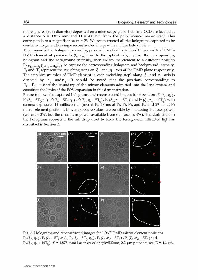
Figure 6 shows the captured holograms and reconstructed images for 6 positions Po o o(ξ ,┟ ) ,
P1 o ξ o(ξ 5T ,┟ )− , P2 o ξ o(ξ 5T ,┟ )+ , P3 o o ┟(ξ ,┟ 5T )− , P4 o o ┟(ξ ,┟ 5T )+ and P5 o o ┟(ξ ,┟ 10T )+ with
camera exposures 12 milliseconds (ms) at Po, 18 ms at P1, P2, P3, and P4, and 29 ms at P5
mirror element positions. Lower exposure values are possible by increasing the laser power
(we use 0.3W, but the maximum power available from our laser is 4W). The dark circle in
the holograms represents the ink drop used to block the background diffracted light as
described in Section 2.
(d)
(e) (f) (g) (h)
(i) (j) (k)
1776 µm 56.9 µm(a) (b) (c)
(l)
Fig. 6. Holograms and reconstructed images for “ON” DMD mirror element positions
P0 )┟,(ξ oo , P1 )┟,5T(ξ oξo − , P2 )┟,5T(ξ oξo + , P3 )5T┟,(ξ ┟oo − , P4 )5T┟,(ξ ┟oo + and
P5 )10T┟,(ξ ┟oo + . S = 1.875 mm; Laser wavelength=532nm; 2.2-µm point source; D = 4.3 cm.
www.intechopen.com
Programmable Point-source Digital In-line Holography Using Digital Micro-mirror Devices
165
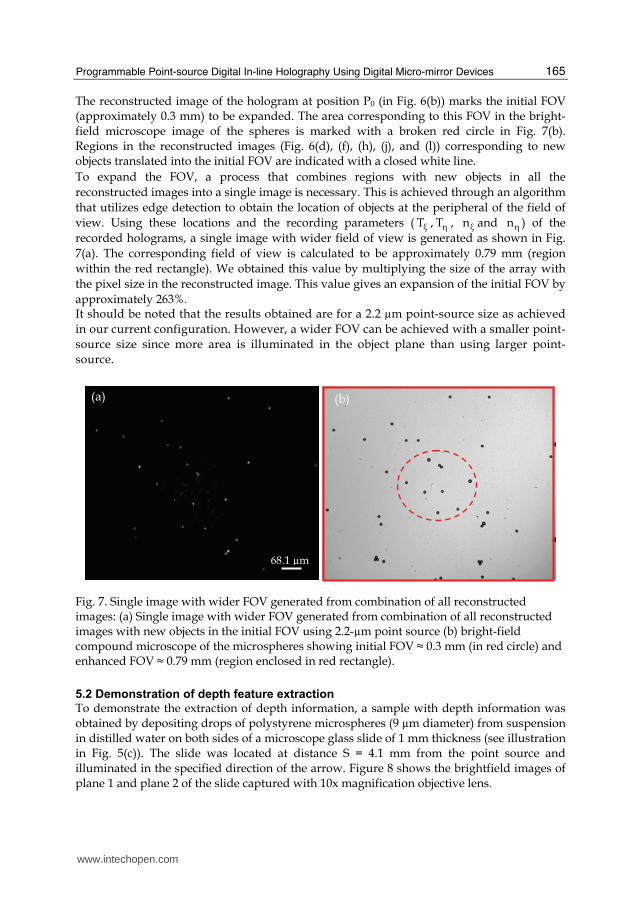
The reconstructed image of the hologram at position P0 (in Fig. 6(b)) marks the initial FOV (approximately 0.3 mm) to be expanded. The area corresponding to this FOV in the bright-field microscope image of the spheres is marked with a broken red circle in Fig. 7(b). Regions in the reconstructed images (Fig. 6(d), (f), (h), (j), and (l)) corresponding to new objects translated into the initial FOV are indicated with a closed white line.
To expand the FOV, a process that combines regions with new objects in all the
reconstructed images into a single image is necessary. This is achieved through an algorithm
that utilizes edge detection to obtain the location of objects at the peripheral of the field of
view. Using these locations and the recording parameters ( ξT , ┟T , ξn and ┟n ) of the
recorded holograms, a single image with wider field of view is generated as shown in Fig.
7(a). The corresponding field of view is calculated to be approximately 0.79 mm (region
within the red rectangle). We obtained this value by multiplying the size of the array with
the pixel size in the reconstructed image. This value gives an expansion of the initial FOV by
approximately 263%. It should be noted that the results obtained are for a 2.2 µm point-source size as achieved
in our current configuration. However, a wider FOV can be achieved with a smaller point-
source size since more area is illuminated in the object plane than using larger point-
source.
68.1 µm
(a) (b)
Fig. 7. Single image with wider FOV generated from combination of all reconstructed images: (a) Single image with wider FOV generated from combination of all reconstructed images with new objects in the initial FOV using 2.2-µm point source (b) bright-field compound microscope of the microspheres showing initial FOV ≈ 0.3 mm (in red circle) and enhanced FOV ≈ 0.79 mm (region enclosed in red rectangle).
5.2 Demonstration of depth feature extraction
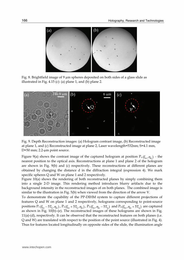
To demonstrate the extraction of depth information, a sample with depth information was obtained by depositing drops of polystyrene microspheres (9 µm diameter) from suspension in distilled water on both sides of a microscope glass slide of 1 mm thickness (see illustration in Fig. 5(c)). The slide was located at distance S = 4.1 mm from the point source and illuminated in the specified direction of the arrow. Figure 8 shows the brightfield images of plane 1 and plane 2 of the slide captured with 10x magnification objective lens.
www.intechopen.com
Holography, Research and Technologies
166
(a) (b)
Fig. 8. Brightfield image of 9 µm spheres deposited on both sides of a glass slide as
illustrated in Fig. 4.15 (c): (a) plane 1, and (b) plane 2.
146.9 µm
Q W
6 µm(a) (b) (c)
Fig. 9. Depth Reconstruction images: (a) Hologram contrast image, (b) Reconstructed image
at plane 1, and (c) Reconstructed image at plane 2, Laser wavelength=532nm; S=4.1 mm,
D=50 mm; 2.2-µm point source.
Figure 9(a) shows the contrast image of the captured hologram at position Po o o(ξ ,┟ ) - the
nearest position to the optical axis. Reconstructions at plane 1 and plane 2 of the hologram
are shown in Fig. 9(b) and (c) respectively. These reconstructions at different planes are
obtained by changing the distance d in the diffraction integral (expression 4). We mark
specific spheres Q and W on plane 1 and 2 respectively. Figure 10(a) shows the rendering of both reconstructed planes by simply combining them
into a single 2-D image. This rendering method introduces blurry artifacts due to the
background intensity in the reconstructed images of on both planes. The combined image is
similar to the illustration in Fig. 5(b) when viewed from the direction of the arrow V.
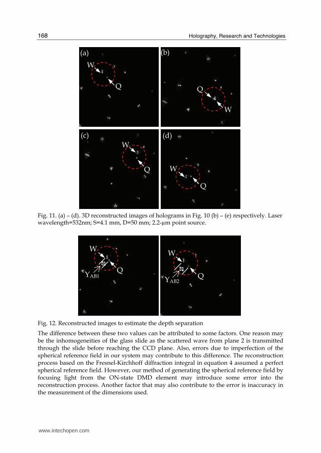
To demonstrate the capability of the PP-DIHM system to capture different projections of
features Q and W on plane 1 and 2 respectively, holograms corresponding to point-source
positions P1 o ξ o(ξ 5T ,┟ )− , P2 o ξ o(ξ 5T ,┟ )+ , P3 o o ┟(ξ ,┟ 5T )− and P4 o o ┟(ξ ,┟ 5T )+ are captured
as shown in Fig. 10(b)–(e). The reconstructed images of these holograms are shown in Fig.
11(a)-(d), respectively. It can be observed that the reconstructed features on both planes (i.e.
Q and W) are translated with respect to the position of the point source (illustrated in Fig. 4).
Thus for features located longitudinally on opposite sides of the slide, the illumination angle
www.intechopen.com

Programmable Point-source Digital In-line Holography Using Digital Micro-mirror Devices
167
┠B is greater than ┠A. This leads to a change in the projection view of the reconstructed
images and lateral shifts between features on both planes. To extract the depth information using expression (9), only two reconstructed holograms are
necessary. For convenience, the images in Fig. 10(a) and Fig. 11(a) are shown in Fig. 12. We
estimate the distances YAB1 and YAB2 (referred to the hologram plane). These distances are
calculated by multiplying the number of image pixels separating Q and W by the CCD (7.4
µm) pixel size. Thus YAB1 and YAB2 are estimated to be 162.3 µm and 418.6 µm respectively.
The translated distance (Δ2) of the point source between positions corresponding to ON-
state DMD element at Po o o(ξ ,┟ ) and P1 o ξ o(ξ 5T ,┟ )− is equivalent to
dmd dmd2
L
N * ΔΔ 114 m.M
μ= = (10)
where dmdN 50= is the number of DMD elements in the translation interval on the DMD
plane, dmdΔ 13.68 mμ= is the DMD pixel size and LM 6= is the magnification between lens
L1 and L2 in Fig. 1. Thus, using expression (9) and given the distance D (between the point
source and CCD plane), and S (between the point source and plane 2 of the slide) as 50mm
and 4.1mm respectively, the depth information (t) separating the two planes can be obtained
as approximately 0.93mm. This value and the known separation (1 mm thickness of the
slide) are quite close.
Q
W6 µm 146.9 µm(a)
(e)(d)
(c)(b)
Fig. 10. (a) Display of both reconstructed plane in Fig. 9; (b)-(e) Hologram at position
P1 o ξ o(ξ - 5T ,┟ ) , P3 o o ┟(ξ ,┟ 5T )+ , P2 ( , 5 )o o Tηξ η − , and P4 o ξ o(ξ 5T ,┟ )+ respectively. Laser
wavelength=532nm; S=4.1 mm, D=50 mm; 2.2-µm point source.
www.intechopen.com
Holography, Research and Technologies
168
Q
W
W
Q
Q
Q W
W
(a) (b)
(c) (d)
Fig. 11. (a) – (d). 3D reconstructed images of holograms in Fig. 10 (b) – (e) respectively. Laser wavelength=532nm; S=4.1 mm, D=50 mm; 2.2-µm point source.
W
W
YAB1YAB2
Fig. 12. Reconstructed images to estimate the depth separation
The difference between these two values can be attributed to some factors. One reason may be the inhomogeneities of the glass slide as the scattered wave from plane 2 is transmitted through the slide before reaching the CCD plane. Also, errors due to imperfection of the spherical reference field in our system may contribute to this difference. The reconstruction process based on the Fresnel-Kirchhoff diffraction integral in equation 4 assumed a perfect spherical reference field. However, our method of generating the spherical reference field by focusing light from the ON-state DMD element may introduce some error into the reconstruction process. Another factor that may also contribute to the error is inaccuracy in the measurement of the dimensions used.
www.intechopen.com

Programmable Point-source Digital In-line Holography Using Digital Micro-mirror Devices
169
6. Discussions
Despite many potential strengths, our DMD-based programmable point-source DIHM system does have challenges. Basically, the main challenges include the new challenges related to the use of the DMD, and more familiar challenges associate with the use of a CCD in holography. Problems introduced by the DMD include background diffraction orders resulting from the 2-D periodic structure of the array and falling within the field of view of the system. These lead to unwanted interference fringes when light from the ON-state element is superimposed, as shown in Fig. 2. For demonstration purposes, our method of reducing the background light in the field of view by locating a cover slide with an ink drop at the back focal plane of lens L1 is quite effective, but introduces complexities in the system. Care is required to locate the cover slide perpendicularly along the beam path and to obtain the required size of the ink drop in comparison to the focused spot size of the background diffracted light. This method at least demonstrates a path to more elegant remediation of this problem through clever spatial filtering. Also, the location of iris P, which blocks some of the diffracted background light, reduces the effective NA of lens L1 in capturing the light beam from the ON-state DMD element. This consequently limits the minimum achievable size of the point source at the focal plane of lens L2. The key to achieving larger NA and removing the complexity introduced by the spatial filter (e.g. ink drop on a cover slide) is to reduce the diffraction effect from the DMD. Given the trends in technological advancement and the general desire to increase contrast, future generations of DMD chips may have less significant diffraction effects. Light scattering from the DMD chip has been improving steadily by advances such as reducing the spacing between the mirror elements and depositing a dark layer on the backplane of the DMD mirror elements. The Gaussian profile of the collimated input beam and its spreading over many DMD elements has potential limiting effects. The spreading of the incident beam leads to low brightness obtained from the ON-state mirror elements. Camera exposure time can be used to compensate for the non-uniform profile of the input beam as the ON-state mirror element is translated away from the origin. However, to achieve high intensity of the light from a single ON-state element, a high-power input laser beam is required. Fortunately, affordable and powerful diode-pumped lasers are available. The challenges associated with the use of CCD in holography are well documented in the literature. In summary, the extent to which a CCD can be located close to the object is limited by the pixel size (affects the sampling of interference pattern) and CCD array size (affects the numerical aperture). Consequently, this also limits the obtainable resolution and restricts the field of view in the reconstructed images. Also, due to the use of a static pinhole in the traditional setup, the obtainable projection view of an object is restricted to only the location of the pinhole. As for strengths of the technique, in addition to enhancing the field of view in the reconstructed image and extracting the axial 3-D information of an object through acquisition of different projections of the hologram, the DMD-based programmable point-source scanning technique provides the flexibility in reconfiguring the size of the point source. This removes the physical limitation imposed by the definite pinhole size in the prior spherical reference-field DIHM configurations. Our approach also eliminates the need for a mechanical scanning procedure in translating the sample or the CCD camera across the beam path.
www.intechopen.com

Holography, Research and Technologies
170
7. Future work
In order to improve the performance of the system under the current configuration and further enhance its application, the following are some research directions to be taken. The current set up takes considerable time to generate the result. This is due to time required to communicate between the various software components to execute certain task. Future work will improve this by speeding up the algorithms implementations and integrating all associated software. Also, an estimation of the background intensity based on a numerical method will potentially improve the speed and eliminate the need to capture background intensity for every point-source position. Another area that needs improvement is the minimum achievable size of the point source. One possibility of reducing the limited size of the point source is to increase the magnification between lens L1 and L2 through the use of more powerful lenses with high NA. For a smaller point source, compared to 2.2 µm in this demonstration, the radial intensity variation in the spherical reference beam profile across the captured hologram field of view is reduced significantly. However, the minimum point source size that can be achieved will also depend on the diffraction limits of the system. Some potentially interesting applications of the programmable point-source DIHM include particle tracking and exploring the advantage of multiple point-source illumination. For the former, the different fields of view in the holograms captured at different scanning positions of the point source can be used to obtain the path taken by an object in the field of view. In principle, multiple point sources can improve depth resolution in DIHM since information about the object from different projections is captured in a single hologram. However, there is need for a smaller point-source size and higher numerical aperture compared to our present configuration. We also envisage a complex reconstruction algorithm will be required to recover the object field due to the multiple point sources of the reference field
8. Conclusion
This chapter has described the technique of programming the point source in digital in-line holographic microscopy using Digital Micro-mirror Devices. By individually addressing the DMD pixels, the location of an ON-state pixel is translated to different locations in the DMD plane. This leads to translation of the source of the spherical reference beam with respect to the object location. Results from the demonstrations showed the system can potentially be used to extract depth information in an object volume and enhance the limited field of view.
9. References
[AD09a] A.A. Adeyemi and T.E. Darcie, Expansion of field of view in digital in-line holography
with a programmable point source, Appl. Opt. vol. 48, pp. 3291-3301, 2009.
[AD09b] A.A. Adeyemi and T.E. Darcie, Extraction of 3D Axial Features in Programmable
Point-Source Digital In-line Holographic Microscope with Spherical Reference Field, IEEE
Pacific Rim (PACRIM) Conference on Communications, Computers and Signal
Processing, pp. 736 – 739, Victoria BC, 2009.
www.intechopen.com

Programmable Point-source Digital In-line Holography Using Digital Micro-mirror Devices
171
[ABD09] A. A. Adeyemi, N. Barakat, and T. E. Darcie, Applications of digital micro-mirror
devices to digital optical microscope dynamic range enhancement, Opt. Express, vol. 17,
Iss. 3, pp. 1831-1843, 2009.
[BPS03] V. Bansal, S. Patel, P. Saggau, A High speed confocal laser-scanning microscope based on
acousto-optic deflectors and a digital micromirror device, Proceedings of the IEEE
conference on engineering in medicine and biology society (Institute of Electrical and
Electronics Engineers, TX), pp. 17-21, 2003.
[CMD99] E. Cuche, P. Marquet, and Ch. Depeursinge, Simultaneous amplitude-contrast and
quantitative phasecontrast microscopy by numerical reconstruction of Fresnel off-axis
holograms, Appl. Opt. vol. 38, pp. 6994-7001, 1999.
[DDS03] D. Dudley, W.M. Duncan, J. Slaughter, Emerging digital micromirror device (DMD)
applications, Proceedings of SPIE, vol. 4985, pp. 14-25, 2003.
[DJL99] F. Dubois, L. Joannes, and J.-C. Legros, Improved three-dimensional imaging with a
digital holographic microscope with a source of partial spatial coherence, Appl. Opt. vol.
38, pp. 7085-7094, 1999.
[DM99] A.L.P. Dlugan and C.E. MacAulay, Update on the use of digital micromirror devices in
quantitative microscopy, Proceeding of SPIE, vol. 3604, pp. 253-262, 1999.
[GPO08] U. Gopinathan, G. Pedrini, and W. Osten, Coherence effects in digital in-line
holographic microscopy, J. Opt. Soc. Am. vol. 25, pp. 2459-2466, 2008.
[GXJKJK06a] J. Garcia-Sucerquia, W. Xu, S.K. Jericho, P. Klages, M.H. Jericho, H.J. Kreuzer,
Digital in-line holographic microscopy, Appl. Opt. vol. 45, pp. 836-850, 2006.
[GXJKJK06b] J. Garcia-Sucerquia, W. Xu, S. Jericho, M. H. Jericho, P. Klages and H.J.
Kreuzer, Resolution power in digital in-line holography, Proceedings of SPIE vol. 6027,
pp. 637-644, 2006.
[JGXJK06] S.K. Jericho, J. Garcia-Sucerquia, W. Xu, M.H. Jericho, H.J. Kreuzer, Submersible
Digital In-line Holographic Microscope, Rev Sci Instrum, vol. 77, 043706, 2006.
[KJMX01] H. J. Kreuzer, M. H. Jerico, I. A. Meinertzhagen, and W. Xu, Digital in-line
holography with photons and electrons, J. Phys.: Condens. Matter vol. 13, pp. 10729–
10741, 2001.
[KN98] K. J. Kearney and Z. Ninkov, Characterization of a digital micromirror device for use as an
optical mask in imaging and spectroscopy, Proceedings of SPIE, vol. 3292, pp. 81-92,
1998.
[Kre05] T. Kreis, Hankbook of holographic interferometry: optical and digital methods, Wiley-VCH,
2005.
[RGMNS06] J. P. Ryle, U. Gopinathan, S. McDonnell, T. J. Naughton, and J. T. Sheridan,
Digital in-line holography of biological specimens, Proceedings of SPIE 6311, 63110C,
2006.
[RPP04] L. Repetto, E. Piano, and C. Pontiggia, Lensless digital holographic microscope with
light-emitting diode illumination, Opt. Lett. vol. 29, pp. 1132-1134, 2004.
[Sch94] U. Schnars, Direct phase determination in hologram interferometry with use of digitally
recorded holograms, J. Opt. Soc. Am. vol. 11, pp. 2011–2015, 1994.
[SJ02] U. Schnars and P. O. Jüptner, Digital recording and numerical reconstruction of holograms,
Meas. Sci. Technol. 13, R85-R101, 2002.
[SJ05] U. Schnars and W. P. Jueptner, Digital Holography, Springer, 2005.
www.intechopen.com

Holography, Research and Technologies
172
[SPISSSW97] B. W. Schilling, T.-Ch. Poon, G. Indebetouw, B. Storrie, K. Shinoda, Y. Suzuki, and M. H. Wu, Three-dimensional holographic fluorescence microscopy, Opt. Lett. vol. 22, pp. 1506-1508, 1997.
[XJMK02a] W. Xu, M. H. Jericho, I. A. Meinertzhagen, and H. J. Kreuzer, Digital In-Line Holography of Microspheres, Appl. Opt. vol. 41, pp. 5367-5375 2002.
[XJMK02b] W. Xu, M. H. Jerico, I. A. Meinertzhagen, and H. J. Kreuzer, Digital in-line holography for biological applications, Proc. Natl. Acad. Sci. USA vol. 98, pp. 11301–11305, 2002.
[Yar03] L. P. Yaroslavsky, Digital Holography and Digital Image Processing: Principles, Methods, Algorithms, Kluwer, 2003.
www.intechopen.com
Holography, Research and TechnologiesEdited by Prof. Joseph Rosen
ISBN 978-953-307-227-2Hard cover, 454 pagesPublisher InTechPublished online 28, February, 2011Published in print edition February, 2011
InTech EuropeUniversity Campus STeP Ri Slavka Krautzeka 83/A 51000 Rijeka, Croatia Phone: +385 (51) 770 447 Fax: +385 (51) 686 166www.intechopen.com
InTech ChinaUnit 405, Office Block, Hotel Equatorial Shanghai No.65, Yan An Road (West), Shanghai, 200040, China
Phone: +86-21-62489820 Fax: +86-21-62489821
Holography has recently become a field of much interest because of the many new applications implementedby various holographic techniques. This book is a collection of 22 excellent chapters written by various experts,and it covers various aspects of holography. The chapters of the book are organized in six sections, startingwith theory, continuing with materials, techniques, applications as well as digital algorithms, and finally endingwith non-optical holograms. The book contains recent outputs from researches belonging to different researchgroups worldwide, providing a rich diversity of approaches to the topic of holography.
How to referenceIn order to correctly reference this scholarly work, feel free to copy and paste the following:
Adekunle A. Adeyemi and Thomas E. Darcie (2011). Programmable Point-source Digital In-line HolographyUsing Digital Micro-mirror Devices, Holography, Research and Technologies, Prof. Joseph Rosen (Ed.), ISBN:978-953-307-227-2, InTech, Available from: http://www.intechopen.com/books/holography-research-and-technologies/programmable-point-source-digital-in-line-holography-using-digital-micro-mirror-devices

© 2011 The Author(s). Licensee IntechOpen. This chapter is distributedunder the terms of the Creative Commons Attribution-NonCommercial-ShareAlike-3.0 License, which permits use, distribution and reproduction fornon-commercial purposes, provided the original is properly cited andderivative works building on this content are distributed under the samelicense.