Programmable AC/DC Power Source - Electronic Test Equipment
210
Programmable AC/DC Power Source ASR-2000 Series USER MANUAL ISO-9001 CERTIFIED MANUFACTURER 99 Washington Street Melrose, MA 02176 Phone 781-665-1400 Toll Free 1-800-517-8431 Visit us at www.TestEquipmentDepot.com
Transcript of Programmable AC/DC Power Source - Electronic Test Equipment
Programmable AC/DC Power Source
ASR-2000 Series
USER MANUAL
ISO-9001 CERTIFIED MANUFACTURER
99 Washington Street Melrose, MA 02176 Phone 781-665-1400Toll Free 1-800-517-8431
Visit us at www.TestEquipmentDepot.com

This manual contains proprietary information, which is protected by copyright. All rights are reserved. No part of this manual may be photocopied, reproduced or translated to another language without prior written consent of Good Will company.
The information in this manual was correct at the time of printing. However, Good Will continues to improve products and reserves the rights to change specification, equipment, and maintenance procedures at any time without notice.
Good Will Instrument Co., Ltd. No. 7-1, Jhongsing Rd., Tucheng Dist., New Taipei City 236, Taiwan.
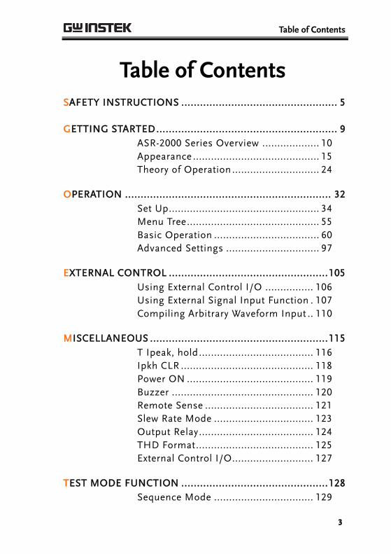
Table of Contents
3
Table of Contents SAFETY INSTRUCTIONS .................................................. 5
GETTING STARTED .......................................................... 9
ASR-2000 Series Overview ................... 10
Appearance .......................................... 15
Theory of Operation ............................. 24
OPERATION .................................................................. 32
Set Up .................................................. 34
Menu Tree ............................................ 55
Basic Operation ................................... 60
Advanced Settings ............................... 97
EXTERNAL CONTROL ................................................... 105
Using External Control I/O ................ 106
Using External Signal Input Function . 107
Compiling Arbitrary Waveform Input .. 110
MISCELLANEOUS ......................................................... 115
T Ipeak, hold ...................................... 116
Ipkh CLR ............................................ 118
Power ON .......................................... 119
Buzzer ............................................... 120
Remote Sense .................................... 121
Slew Rate Mode ................................. 123
Output Relay ...................................... 124
THD Format ....................................... 125
External Control I/O........................... 127
TEST MODE FUNCTION ............................................... 128
Sequence Mode ................................. 129
ASR-2000 Series User Manual
4
Simulate Mode ................................... 145
COMMUNICATION INTERFACE .................................... 159
Interface Configuration ...................... 160
FAQ .............................................................................. 180
APPENDIX .................................................................... 181
Firmware Update ............................... 181
Factory Default Settings ..................... 183
Error Messages & Messages .............. 187
Specifications .................................... 193
Information of Name Order ............... 201
ASR-2000 Dimensions ........................ 202
Declaration of Conformity .................. 206
Maintenance & Regular Inspection .... 207
INDEX .......................................................................... 209
SAFETY INSTRUCTIONS
5
SAFETY INSTRUCTIONS This chapter contains important safety instructions that you must follow during operation and storage. Read the following before any operation to ensure your safety and to keep the instrument in the best possible condition.
Safety Symbols
These safety symbols may appear in this manual or on the instrument.
WARNING Warning: Identifies conditions or practices that could result in injury or loss of life.
CAUTION Caution: Identifies conditions or practices that could result in damage to the ASR-2000 or to other properties.
DANGER High Voltage
Attention Refer to the Manual
Protective Conductor Terminal
Earth (ground) Terminal
ASR-2000 Series User Manual
6
Do not dispose electronic equipment as unsorted municipal waste. Please use a separate collection facility or contact the supplier from which this instrument was purchased.
Safety Guidelines
General Guideline
CAUTION
Do not place any heavy object on the ASR-2000.
Avoid severe impact or rough handling that leads to damaging the ASR-2000.
Do not discharge static electricity to the ASR-2000.
Use only mating connectors, not bare wires, for the terminals.
Do not block the cooling fan opening.
Do not disassemble the ASR-2000 unless you are qualified.
If the equipment is used in a manner not specified by the manufacturer, the protection provided by the equipment may be impaired.
(Measurement categories) EN 61010-1:2010 specifies the measurement categories and their requirements as follows. The ASR-2000 doesn’t fall under category II, III or IV.
Measurement category IV is for measurement performed at the source of low-voltage installation.
Measurement category III is for measurement performed in the building installation.
Measurement category II is for measurement performed on the circuits directly connected to the low voltage installation.
0 is for measurements performed on circuits not directly connected to Mains.
SAFETY INSTRUCTIONS
7
Power Supply
WARNING
AC Input voltage range:
100 ~ 240 Vac
Frequency: 47 ~ 63 Hz
To avoid electrical shock connect the protective grounding conductor of the AC power cord to an earth ground.
The power switch that is included in the instrument is not considered a disconnecting device.
The power cord set is used as the disconnecting device and shall remain readily operable.
Do not position the equipment so that it is difficult to operate the disconnecting device.
Do not replace the power supply cord with an improperly rated cord. A certified power supply cord should not lighter than light PVC sheathed flexible cord according to IEC 60227, designation H05VV-F, and be rated for at least 3G 0.75 mm² (for rated current up to 10 A) or 3G 1.0mm² (for rated current over 10 A up to 16 A) wire or larger, and the length of the cord that does not exceed 2 m must be used.
Cleaning the ASR-2000
Disconnect the power cord before cleaning.
Use a soft cloth dampened in a solution of mild detergent and water. Do not spray any liquid.
Do not use chemicals containing harsh material such as benzene, toluene, xylene, and acetone.
Operation Environment
Location: Indoor, no direct sunlight, dust free, almost non-conductive pollution (Note below)
Relative Humidity: 20%~ 80%, no condensation
Altitude: < 2000m
Temperature: 0°C to 40°C

ASR-2000 Series User Manual
8
(Pollution Degree) EN 61010-1:2010 specifies the pollution degrees and their requirements as follows. The ASR-2000 falls under degree 2.
Pollution refers to “addition of foreign matter, solid, liquid, or gaseous (ionized gases), that may produce a reduction of dielectric strength or surface resistivity”.
Pollution degree 1: No pollution or only dry, non-conductive pollution occurs. The pollution has no influence.
Pollution degree 2: Normally only non-conductive pollution occurs. Occasionally, however, a temporary conductivity caused by condensation must be expected.
Pollution degree 3: Conductive pollution occurs, or dry, non-conductive pollution occurs which becomes conductive due to condensation which is expected. In such conditions, equipment is normally protected against exposure to direct sunlight, precipitation, and full wind pressure, but neither temperature nor humidity is controlled.
Storage environment
Location: Indoor
Temperature: -10°C to 70°C
Relative Humidity: ≤90%, no condensation
Disposal
Do not dispose this instrument as unsorted municipal waste. Please use a separate collection facility or contact the supplier from which this instrument was purchased. Please make sure discarded electrical waste is properly recycled to reduce environmental impact.

GETTING STARTED
9
GETTING STARTED This chapter describes the ASR-2000 power supply in a nutshell, including its main features and front / rear panel introduction.
ASR-2000 ASR-2000R
ASR-2000 Series Overview ...................................... 10 Series lineup ...................................................................................... 10 Operating Area ................................................................................. 10 Main Features ................................................................................... 12 Accessories ........................................................................................ 13
Appearance ............................................................ 15 Front Panel ........................................................................................ 15 Rear Panel .......................................................................................... 20 Status Bar Icons ............................................................................... 23
Theory of Operation ............................................... 24 Description of ASR-2000 System ................................................. 24 Glossary ............................................................................................. 25 Alarms ................................................................................................ 27 Considerations .................................................................................. 29 Grounding ......................................................................................... 31
ASR-2000 Series User Manual
10
ASR-2000 Series Overview
Series lineup
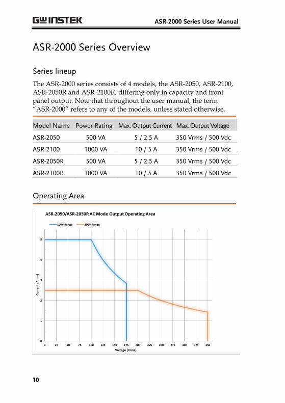
The ASR-2000 series consists of 4 models, the ASR-2050, ASR-2100, ASR-2050R and ASR-2100R, differing only in capacity and front panel output. Note that throughout the user manual, the term “ASR-2000” refers to any of the models, unless stated otherwise.
Model Name Power Rating Max. Output Current Max. Output Voltage
ASR-2050 500 VA 5 / 2.5 A 350 Vrms / 500 Vdc
ASR-2100 1000 VA 10 / 5 A 350 Vrms / 500 Vdc
ASR-2050R 500 VA 5 / 2.5 A 350 Vrms / 500 Vdc
ASR-2100R 1000 VA 10 / 5 A 350 Vrms / 500 Vdc
Operating Area

GETTING STARTED
11
ASR-2000 Series User Manual
12
Main Features
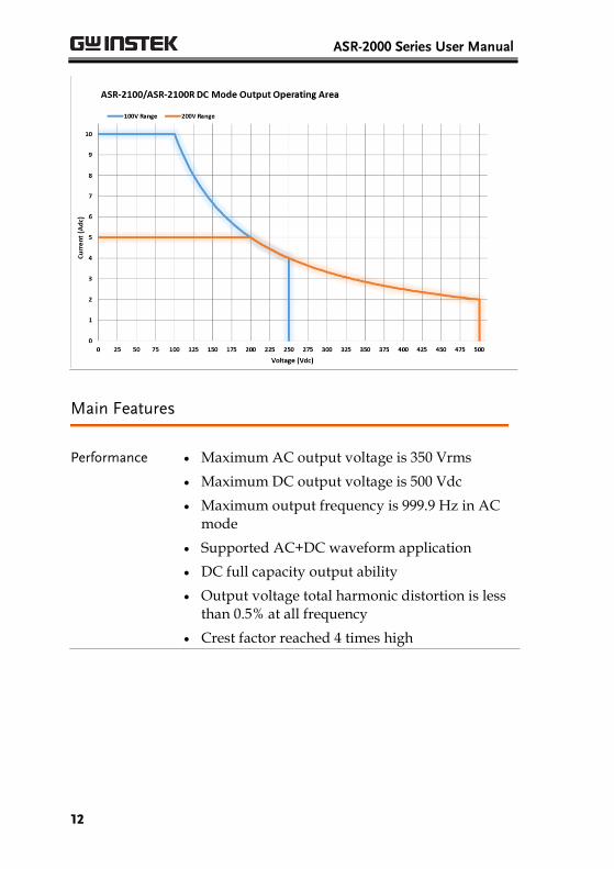
Performance Maximum AC output voltage is 350 Vrms
Maximum DC output voltage is 500 Vdc
Maximum output frequency is 999.9 Hz in AC mode
Supported AC+DC waveform application
DC full capacity output ability
Output voltage total harmonic distortion is less than 0.5% at all frequency
Crest factor reached 4 times high

GETTING STARTED
13
Features Include sine, square, triangle, arbitrary and DC
output waveforms
Variable voltage, frequency and current limiter
Harmonic voltage and current analysis ability
Excellent and feature-rich measurement capacity
Sequence and simulate function
External input amplification
AC line synchronized output
Preset memory function
USB memory support
Remote sense
OCP, OPP and OTP protection function
Interface Built-in LAN, USB host and USB device interface
External control I/O
External signal input
Factory option RS232 and GPIB interface
Accessories
Before using the ASR-2000 power source unit, check the package contents to make sure all the standard accessories are included.
Standard Accessories
Part number Description
CD ROM User manual, programming manual
82GW1SAFE0M*1 Safety guide
Region dependent Power cord
63SC-XF101601 x 1 Mains terminal cover set
63SC-XF101701 x 1 Remote sensing cover set

ASR-2000 Series User Manual
14
GTL-123 Test leads: 1x red, 1x black
GTL-246 USB CABLE (USB 2.0 Type A- Type B Cable, Approx. 1.2M)
Factory Installed Options
Part number Description
Optional 1 RS232 + GPIB interface
Optional 2 European Output Socket
Optional Accessories
Part number Description
GET-003 Universal extended terminal box
(ASR-2000R only)
GET-004 EURO extended terminal box (ASR-2000R only)
GRA-439-E Rack mount adapter (EIA)
GRA-439-J Rack mount adapter (JIS)
GTL-232 RS232C cable, approx. 2M
GTL-258 An approximately 2M in length GPIB Cable including 25 pins Micro-D connector
ASR-001 Air inlet filter
Download Name Description
gw_asr.inf USB driver

GETTING STARTED
15
Appearance
Front Panel
M 1 6 2 B
F G
C
H
D E
J
I
5
4A97 8K 3
L
Item Index Description
1 Power switch button
2 USB interface connector (A Type)
3 LCD screen
4 Display mode select key
5 Function keys (blue zone)
6 Lock/Unlock button
7 V/V-Limit button
8 F/F-Limit button
9 Irms/IPK-Limit button
A Range key/Output mode key

ASR-2000 Series User Manual
16
B Menu key/On phase key
C Shift key
D Test key/Output waveform key
E Enter key
F Preset key/Local mode key
G Cancel key/ALM CLR key
H Output key
I Scroll wheel
J Arrow keys
K Air inlet
L Hardcopy key
M Output socket (ASR-2100/2050 only)

GETTING STARTED
17
Item Description
Power Switch
Turn on the mains power
USB A Port
The USB port is used for data transfers and upgrading software. Also, it is available for screenshot hardcopy in association with the Hardcopy key.
LCD Screen Displays the setting and measured values or menu system
Display Mode Select Key
Selects between standard, simple and harmonic analysis mode
Function Keys
Assigned to the functions displayed on the right side of the screen
Lock/Unlock Key
Used to lock or unlock the front panel keys except output key. Simply press to lock, whilst long press to unlock.
Shift Key
Turns on the shift state, which enables shortcut operations with an icon indicated on the top status bar. The shift state, which allows continuous shortcut operations, is kept until another press on shift key again.
Note When performing shortcut operations, press shift key followed by another shortcut function key. Do Not press both shift key and shortcut function key simultaneously.

ASR-2000 Series User Manual
18
V
Used for setting the output voltage
V-Limit +
Used for setting the output voltage limit value
F
Used for setting the output frequency (DC mode N/A)
F-Limit +
Used for setting the output frequency limit value (DC mode N/A)
Irms
Used for setting the maximum output current
IPK-Limit +
Used to set the peak output current limit value
Range Key Switches between the 100V, 200V and AUTO ranges
Output Mode +
Selects between the AC+DC-INT, AC-INT, DC-INT, AC+DC-EXT, AC-EXT, AC+DC-ADD, AC-ADD, AC+DC-Sync and AC-Sync modes
Menu Key
Enters the Main menu or goes back to one of the display modes.
On Phase +
Sets the on phase for the output voltage
Test Key
Puts the instrument into the Sequence and Simulation control mode.
Output Waveform +
Selects between the Sine, Square, Triangle and ARB 1~16 waveforms
(not available for DC-INT, AC+DC-EXT and AC-EXT)
GETTING STARTED
19
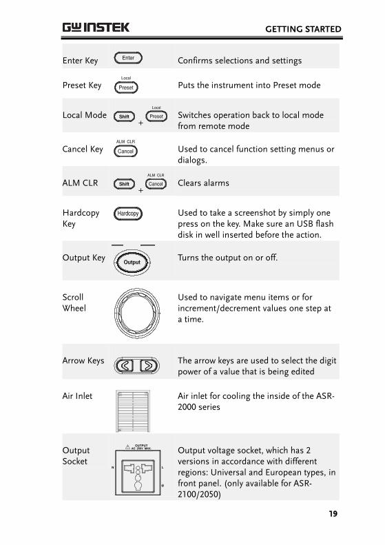
Enter Key Confirms selections and settings
Preset Key
Puts the instrument into Preset mode
Local Mode +
Switches operation back to local mode from remote mode
Cancel Key
Used to cancel function setting menus or dialogs.
ALM CLR +
Clears alarms
Hardcopy Key
Used to take a screenshot by simply one press on the key. Make sure an USB flash disk in well inserted before the action.
Output Key
Turns the output on or off.
Scroll Wheel
Used to navigate menu items or for increment/decrement values one step at a time.
Arrow Keys
The arrow keys are used to select the digit power of a value that is being edited
Air Inlet
Air inlet for cooling the inside of the ASR-2000 series
Output Socket
Output voltage socket, which has 2 versions in accordance with different regions: Universal and European types, in front panel. (only available for ASR-2100/2050)

ASR-2000 Series User Manual
20
Rear Panel
3478
9
5
2 16
Item Index Description
1 Line input
2 Output terminal
3 Remote sensing input terminal
4 Exhaust fan
5 External I/O connector
6 External signal input/ External synchronized signal input
7 USB interface connector (B Type)
8 Ethernet (LAN) connector
9 Optional 1 interfaces (RS232C & GPIB connectors)

GETTING STARTED
21
Item Description
Line Input
AC inlet
Output Terminal
Output voltage terminal (M3 screw type, 10 ~ 18 AWG)
Remote Sensing Input Terminal
Compensation of load wire voltage drop. Only +S and –S are available for compensation. N.C. terminals are N/A. Refer to page 98 for details.
Exhaust Fan
The exhaust fan is used to expel the heat from the unit. Please ensure there is at least 20 cm distance between any object and the fan.
External Control I/O Connector
Used to control ASR-2000 externally by using the logic signal and monitor Sequence function status
External Signal Input Connector
Synchronizing the output frequency with this external input signal for SYNC or outputting the amplified external signal with this external input signal for EXT and ADD.
ASR-2000 Series User Manual
22
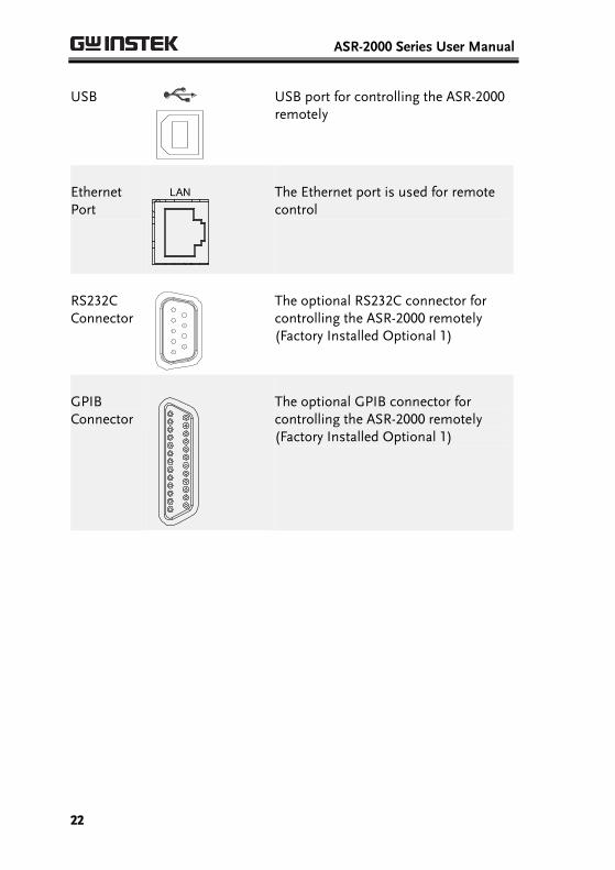
USB USB port for controlling the ASR-2000 remotely
Ethernet Port
The Ethernet port is used for remote control
RS232C Connector
The optional RS232C connector for controlling the ASR-2000 remotely (Factory Installed Optional 1)
GPIB Connector
The optional GPIB connector for controlling the ASR-2000 remotely (Factory Installed Optional 1)
GETTING STARTED
23
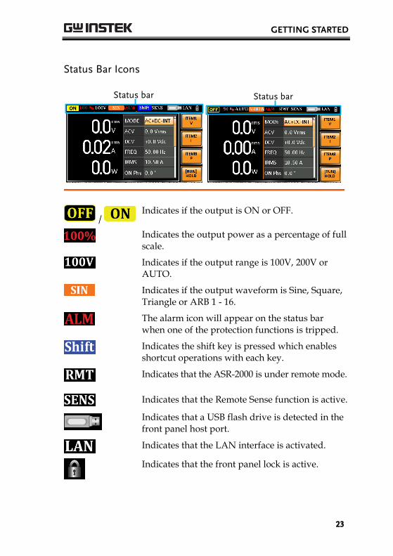
Status Bar Icons
Status bar
Status bar
/ Indicates if the output is ON or OFF.
Indicates the output power as a percentage of full scale.
Indicates if the output range is 100V, 200V or AUTO.
Indicates if the output waveform is Sine, Square, Triangle or ARB 1 - 16.
The alarm icon will appear on the status bar when one of the protection functions is tripped.
Indicates the shift key is pressed which enables shortcut operations with each key.
Indicates that the ASR-2000 is under remote mode.
Indicates that the Remote Sense function is active.
Indicates that a USB flash drive is detected in the front panel host port.
Indicates that the LAN interface is activated.
Indicates that the front panel lock is active.
ASR-2000 Series User Manual
24
Theory of Operation The theory of operation chapter describes the basic principles of operation, protection modes and important considerations that must be taken into account before use.
Description of ASR-2000 System
System block are composed of the parts described below.
Input EMI Filter and PFC Circuit
A two stage π filter and a passive PFC circuit that convert AC power to DC power.
Auxiliary Power It converts AC power line input to +24Vdc power for the PWM ICs, fan, among other devices.
Isolation DC to DC Converter
The isolation DC to DC converter is able to convert high DC level to lower that not only offers inverter a stable DC source but separates primary and secondary side efficiently.
Output Power Stage (inverter)
Two inverter power stages are in parallel or in series that provide, in addition to AC and DC output, sinusoid, square as well as triangle output waveforms.
Digital Processor and Close Loop Control Circuit
Composition of the C2000 DSP device and the closed-loop control circuit that execute inverter action, output measurement and all of the relevant protection functions.
Communication Interface and Data Transmission
DSP, FPGA and LCD controller that are collectively responsible for interface communication, data transmission, LED panel control as well as remote control.
Keypad and Display
CPLD that controls keys action and communicates with DSP for data transmission.
GETTING STARTED
25
Glossary
Rate Output Maximum Power Capacity
The maximum value of the output power capacity will be provided consecutively when the following situations exist:
Output voltage is 100 to 175 V within the 100 V range.
Output voltage is 200 to 350 V within the 200 V range.
Output frequency is 40 to 999.9 Hz in AC mode.
Output frequency is 1 to 999.9 Hz in AC+DC mode.
Output voltage is 100 to 250 V within the 100 V range in DC mode.
Output voltage is 200 to 500 V within the 200 V range in DC mode.
Rate Maximum Current
The maximum value of the output current (rms value) will be provided consecutively when the following situations exist:
Output voltage is 100 V within the 100 V range.
Output voltage is 200 V within the 200 V range.
Output frequency is 40 to 999.9 Hz in AC mode.
Output frequency is 1 to 999.9 Hz in AC+DC mode.
Output voltage is 100 V within the 100 V range in DC mode.
Output voltage is 200 V within the 200 V range in DC mode.
Note The maximum capacity and current in DC mode is equal to AC+ DC and AC mode.
ASR-2000 Series User Manual
26
Equation:
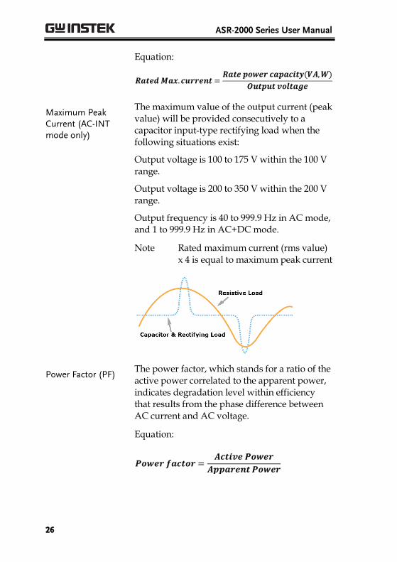
Maximum Peak Current (AC-INT mode only)
The maximum value of the output current (peak value) will be provided consecutively to a capacitor input-type rectifying load when the following situations exist:
Output voltage is 100 to 175 V within the 100 V range.
Output voltage is 200 to 350 V within the 200 V range.
Output frequency is 40 to 999.9 Hz in AC mode, and 1 to 999.9 Hz in AC+DC mode.
Note Rated maximum current (rms value) x 4 is equal to maximum peak current
Power Factor (PF) The power factor, which stands for a ratio of the active power correlated to the apparent power, indicates degradation level within efficiency that results from the phase difference between AC current and AC voltage.
Equation:

GETTING STARTED
27
Crest Factor (CF) The crest factor stands for a ratio of the rms value correlated to the peak value (crest value) of the waveform.
Equation:
Note The crest factor is 1.41 of sine wave.
Inrush Current Capacity
It indicates the current, which is able to be supplied to a load, exceeds the rating for a short period and the duration.
Output Power Ratio
It indicates the output power of a percentage where the rated maximum output power is 100%.
Alarms
The ASR-2000 series have a number of protection features. When one of the protection alarms is tripped, the ALM icon on the display will be lit and the type of alarm that has been tripped will be shown on the display. When an alarm has been tripped the output will be automatically turned off. For details on how to clear an alarm or to set the protection modes, please see page 187.
Abnormal Output This alarm is activated and output will be disabled immediately when output overvoltage or overcurrent is detected.
Abnormal Power Source Block
This alarm is activated and output will be disabled immediately when internal power source abnormality is detected. Beware that all operations will be disabled except for the power shutdown operation if an error occurs.
ASR-2000 Series User Manual
28
Abnormal Internal Control
This alarm is activated and output will be disabled immediately when internal control abnormality is detected. Beware that all operations will be disabled except for the power shutdown operation if an error occurs.
V-Limit Voltage limit protection prevents a high voltage from damaging the DUT. This alarm can be set by the user.
F-Limit Frequency limit protection prevents a high frequency from damaging the DUT. This alarm can be set by the user.
OCP Over current protection prevents high current from damaging the DUT. This alarm can be set by the user.
OTP Over temperature protection for power stage board. OTP is a hardware protection function. Only when the unit has cooled can the over temperature protection alarms be cleared.
Remote Sense Error
Sense alarm. This alarm will detect if the sense wires have been connected to the wrong polarity.
AC Fail AC failure. This alarm function is activated when a low AC input is detected.
FAN Fail Fan failure. This alarm function is activated when the fan RPMs drop to an abnormally low level.

GETTING STARTED
29
Considerations
The following situations should be taken into consideration when using the power supply.
Inrush Current
When the power supply switch is first turned on, an inrush current is generated. Ensure there is enough power available for the power supply when first turned on, especially if a number of units are turned on at the same time.
Capacitive Load When the power supply connects to a capacitive load, e.g., capacitor, the load is being charged consecutively and the larger the voltage change, the more the current grow. Also, the overshoot will be possibly generated within the currents output, therefore leading to output turned off thanks to overcurrent protection from the power supply.
It is suggested to lower down the set voltage output from power supply so that the voltage of capacitive load decreases per certain unit time. In addition, a block diode is necessary to keep current from flowing back to the output terminal of power supply. Refer to the figure below where a block diode connects with the capacitive load in series to efficiently prevent current from flowing back to the power supply.
L
N
Capacitive Load
Block DiodeASR-2000
ASR-2000 Series User Manual
30
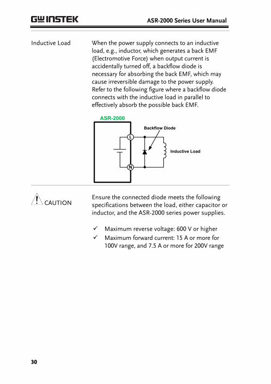
Inductive Load When the power supply connects to an inductive load, e.g., inductor, which generates a back EMF (Electromotive Force) when output current is accidentally turned off, a backflow diode is necessary for absorbing the back EMF, which may cause irreversible damage to the power supply. Refer to the following figure where a backflow diode connects with the inductive load in parallel to effectively absorb the possible back EMF.
L
N
Inductive Load
Backflow Diode
ASR-2000
CAUTION Ensure the connected diode meets the following specifications between the load, either capacitor or inductor, and the ASR-2000 series power supplies.
Maximum reverse voltage: 600 V or higher
Maximum forward current: 15 A or more for 100V range, and 7.5 A or more for 200V range
GETTING STARTED
31
Grounding
The output terminals of the ASR-2000 series are isolated with respect to the protective grounding terminal. The insulation capacity of the load, the load cables and other connected devices must be taken into consideration when connected to the protective ground or when floating.
Grounded Neutral Output
Basically, grounded return on the neutral output is allowed for ASR-2000 series and electric shock may occur if not following the grounding procedure based on the local electrical safety codes. In some cases, 0 V is specifically required between ground and neutral, which can substantially moderate ground loops, thus keeping sensitive equipment from effects of ground loops and reducing ground noise.
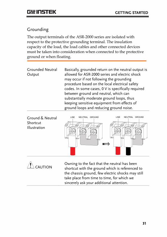
Ground & Neutral Shortcut Illustration
LINE NEUTRAL GROUND
LINE NEUTRAL GROUND
CAUTION Owning to the fact that the neutral has been shortcut with the ground which is referenced to the chassis ground, few electric shocks may still take place from time to time, for which we sincerely ask your additional attention.

ASR-2000 Series User Manual
32
OPERATION
Set Up .................................................................... 34 Power Up ........................................................................................... 34 How to Use the Instrument ........................................................... 35 Output Terminals ............................................................................. 38 Installing GET-003/GET-004 Box Series (ASR-2000R only) 41 Using the Rack Mount Kit ............................................................. 44 Reset to Factory Default Settings .................................................. 46 View Firmware Version and Serial Number ............................... 47 LCD Configuration.......................................................................... 48 USB Driver Installation .................................................................. 49 Filter Installation .............................................................................. 51 Wire Gauge Considerations ........................................................... 53
Menu Tree .............................................................. 55 Main Page .......................................................................................... 56 Function Keys................................................................................... 57 Menu................................................................................................... 59
Basic Operation ...................................................... 60 Select the Output Mode .................................................................. 61 Select the Voltage Range................................................................. 62 Select the Output Waveform ......................................................... 63 Setting the Frequency Limit ........................................................... 71 Setting the Output Frequency & Signal ....................................... 74 Setting the Peak Current Limit ...................................................... 76 Setting the Output Current Level ................................................. 79 Setting the Output On Phase ......................................................... 82 Setting the Output Off Phase ........................................................ 84 Switch the Display Modes .............................................................. 86 Using the Measurement Function ................................................. 89 Switch the Measurement Format .................................................. 92 Panel Lock ......................................................................................... 94 Alarm Clear ....................................................................................... 95 Turning the Output On/Off ......................................................... 96
Advanced Settings .................................................. 97 Using the Remote Sense Function ................................................ 97
Local Sense ........................................................................... 97
OPERATION
33
Remote Sense ...................................................................... 98 Preset Settings ................................................................................. 100
Save Preset Settings to Local Memory .......................... 100 Load Preset Settings to Local Memory ......................... 101 Manage Preset Settings .................................................... 102

ASR-2000 Series User Manual
34
Set Up
Power Up
Steps 1. Connect the power cord to the rear panel socket.
2. Press the POWER key. The splash screen will
appear momentarily before the continuous mode screen appears with the settings loaded.
CAUTION The power supply takes around 15 seconds to fully turn on and shutdown.
Do not turn the power on and off quickly.

OPERATION
35
How to Use the Instrument
Background The ASR-2000 AC power supplies generally use the scroll wheel, Arrow keys and Enter keys to edit numerical values or to select menu options.
Menu navigation is performed using the menu keys and function keys on the front panel.
The following section will explain some of these concepts in detail.
Selecting Menu Items
1. Turn the scroll wheel to select parameters in menus and lists. The selected parameter will be highlighted in orange. The scroll wheel is also used to increment/decrement setting values.
2. Press the Enter key to edit the parameter or to enter the selected menu.
Example The following is an example of the menu list that appears when the Menu key is pressed.
Selected parameter
ASR-2000 Series User Manual
36
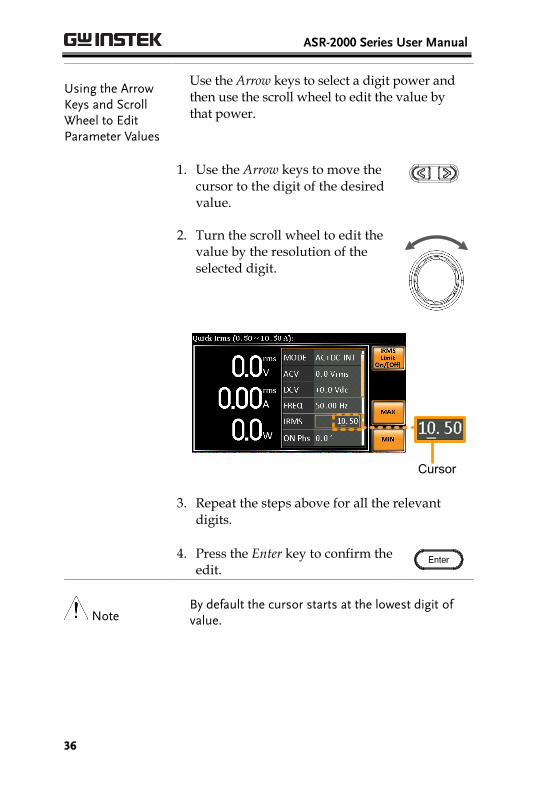
Using the Arrow Keys and Scroll Wheel to Edit Parameter Values
Use the Arrow keys to select a digit power and then use the scroll wheel to edit the value by that power.
1. Use the Arrow keys to move the cursor to the digit of the desired value.
2. Turn the scroll wheel to edit the value by the resolution of the selected digit.
Cursor
3. Repeat the steps above for all the relevant
digits.
4. Press the Enter key to confirm the edit.
Note By default the cursor starts at the lowest digit of value.

OPERATION
37
Using the Function Keys
The function keys are quick settings keys, the function of which depends on the current menu or operation.
1. Press the Function key that corresponds to the setting directly to its left side.
2. The setting or parameter is immediately executed.
Function keys
Corresponding quick settings
3. Repeat the steps above for all the relevant
digits.
ASR-2000 Series User Manual
38
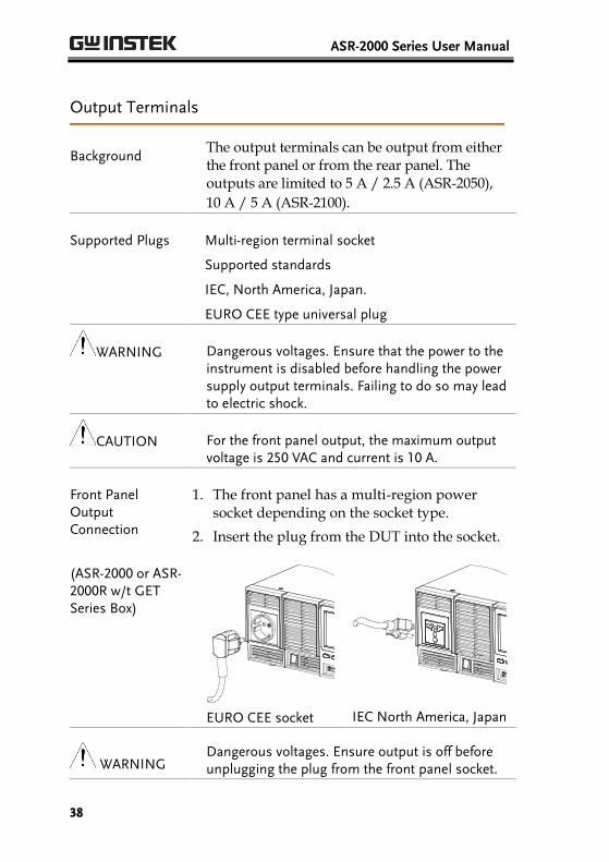
Output Terminals
Background The output terminals can be output from either the front panel or from the rear panel. The outputs are limited to 5 A / 2.5 A (ASR-2050),
10 A / 5 A (ASR-2100).
Supported Plugs
Multi-region terminal socket
Supported standards
IEC, North America, Japan.
EURO CEE type universal plug
WARNING Dangerous voltages. Ensure that the power to the instrument is disabled before handling the power supply output terminals. Failing to do so may lead to electric shock.
CAUTION For the front panel output, the maximum output voltage is 250 VAC and current is 10 A.
Front Panel Output Connection
1. The front panel has a multi-region power socket depending on the socket type.
2. Insert the plug from the DUT into the socket.
(ASR-2000 or ASR-2000R w/t GET Series Box)
EURO CEE socket
IEC North America, Japan
WARNING Dangerous voltages. Ensure output is off before unplugging the plug from the front panel socket.
OPERATION
39
WARNING Except for the AC-INT, AC-EXT and AC-Sync modes, the terminal outputs DC voltage as well.
3. Turn the power on. The AC power supply is now ready to power the DUT.
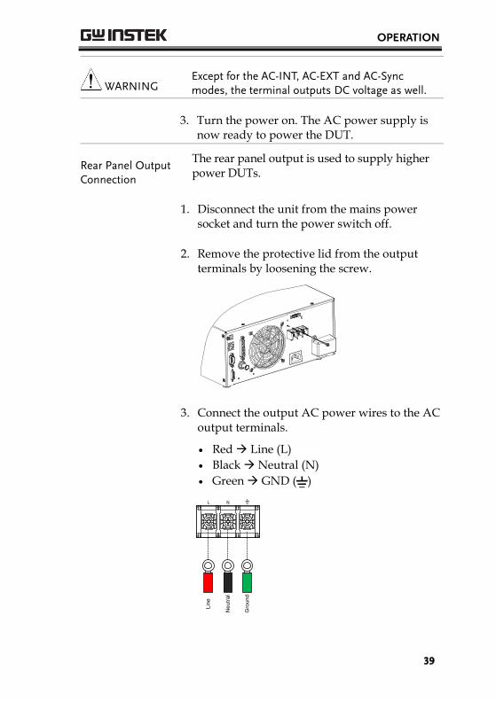
Rear Panel Output Connection
The rear panel output is used to supply higher power DUTs.
1. Disconnect the unit from the mains power socket and turn the power switch off.
2. Remove the protective lid from the output terminals by loosening the screw.
3. Connect the output AC power wires to the AC output terminals.
Red Line (L)
Black Neutral (N)
Green GND ( )
Line
Neu
tral
Gro
und

ASR-2000 Series User Manual
40
4. Cover the protective lid onto the output
terminals as the figure below shown.
5. Fasten the screw of protective lid with the unit.
6. Turn the power on. The AC power supply is
now ready to power the DUT.
Note Grounded Neutral Output: ASR-2000 allows for a grounded return on the neutral output. It is suit for the medical industry that required between ground with neutral is 0 V essentially. And possible to mitigate ground loops that is ideal for reduce ground noise and isolate sensitive equipment from the effects of ground loops.
WARNING Because the neutral has been referenced to the chassis ground, be careful electric shock by yourself.
OPERATION
41
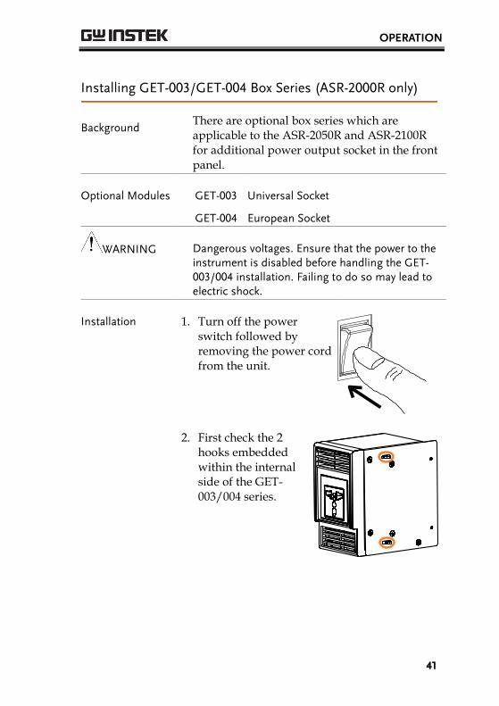
Installing GET-003/GET-004 Box Series (ASR-2000R only)
Background There are optional box series which are applicable to the ASR-2050R and ASR-2100R for additional power output socket in the front panel.
Optional Modules
GET-003 Universal Socket
GET-004 European Socket
WARNING Dangerous voltages. Ensure that the power to the instrument is disabled before handling the GET-003/004 installation. Failing to do so may lead to electric shock.
Installation 1. Turn off the power switch followed by removing the power cord from the unit.
2. First check the 2 hooks embedded within the internal side of the GET-003/004 series.

ASR-2000 Series User Manual
42
3. Align the 2 hooks of GET-003/004 with the 2 rectangular grooves on the flank of ASR-2000R unit and slide GET-003/004 horizontally.
4. Gently slide the GET-003/004 into place until
click to have it level with ASR-2000R evenly.
5. Fasten the 2 screws in the rear side of GET-003/004 with bare hands easily.
OPERATION
43
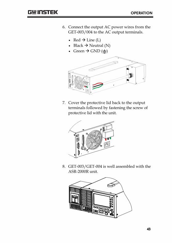
6. Connect the output AC power wires from the
GET-003/004 to the AC output terminals.
Red Line (L)
Black Neutral (N)
Green GND ( )
7. Cover the protective lid back to the output
terminals followed by fastening the screw of protective lid with the unit.
8. GET-003/GET-004 is well assembled with the
ASR-2000R unit.

ASR-2000 Series User Manual
44
Using the Rack Mount Kit
Background The ASR-2000 and ASR-2000R have the following optional Rack Mount kits, respectively.
Unit Model Rack Mount kit part
number
ASR-2000
ASR-2000R GRA-439-E
ASR-2000
ASR-2000R GRA-439-J
The GRA-439-E is designed to fit into an EIA rack of 3U-height, while the GRA-439-J is designed to fit into a JIS rack of 3U-height. Please see your distributor for further rack mount details.
GRA-439-E Series
GRA-439-E Rack Mount Diagram (ASR-2000)
GRA-439-E Rack Mount Diagram (ASR-2000R)
GRA-439-E Rack Mount Diagram (Dual ASR-2000Rs)

OPERATION
45
GRA-439-J Series
GRA-439-J Rack Mount Diagram (ASR-2000)
GRA-439-J Rack Mount Diagram (ASR-2000R)
GRA-439-J Rack Mount Diagram (Dual ASR-2000Rs)
CAUTION Ensure adequate ventilation is provided when using the rack mount. Ensure that a gap is given for air intakes. Failure to do so may cause the instrument to overheat.

ASR-2000 Series User Manual
46
Reset to Factory Default Settings
Background The default settings can be restored from the Menu key settings. See page 183 for the default factory settings.
Steps 1. Press the Menu key. The Menu settings will appear on the display.
2. Use the scroll wheel to go to item 8, Default Setting.
3. Press Enter for 2 times to restore the unit back to the default settings.
Default settings

OPERATION
47
View Firmware Version and Serial Number
Background The Menu>System Information setting displays the serial number and firmware version.
Steps 1. Press the Menu key. The Menu setting will appear on the display.
2. The system information should now be listed in the item 1, System Information, on the display
Exit 3. Press Exit[F4] to exit from the Menu settings.
System Information
Exit [F4]

ASR-2000 Series User Manual
48
LCD Configuration
Background The LCD Configuration setting sets the brightness, contrast and saturation level of the LCD display.
Steps 1. Press the Menu key. The Menu settings will appear on the display.
2. Use the scroll wheel to go to item 7, LCD Configuration and press Enter.
3. Set the brightness, contrast and saturation.
Contrast(%) 1 ~ 100% (Default=50%)
Brightness(%) 1 ~ 100% (Default=50%)
Saturation(%) 1 ~ 100% (Default=50%)
Exit 4. Press Exit[F4] to exit from the LCD Configuration settings.
Default Settings 5. Press Default[F3] to set all the LCD settings to 50%.
LCD Configuration
Default settings [F3]
Exit [F4]

OPERATION
49
USB Driver Installation
Background If the USB Type B interface is to be used for remote control, the USB driver needs to be installed.
Note
The USB driver, gw_asr.inf, can be downloaded from the GW Instek website.
For information on the USB interface, see page 161.
Steps 1. Connect the rear panel USB -B port on the ASR-2000 to the PC using a USB Type A to B cable.
2. Go the Windows Device Manager.
For Windows 7: Start > Control Panel > Hardware and Sound > Device Manager
Note It is available for Windows 7 and Windows 10.
3. The ASR-2000 will be located under Other Devices in the hardware tree. Right-click the ASR-2XXX and choose Update Driver Software.
ASR-2000 Series User Manual
50
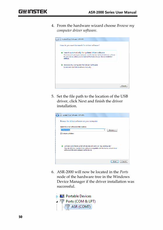
4. From the hardware wizard choose Browse my computer driver software.
5. Set the file path to the location of the USB driver, click Next and finish the driver installation.
6. ASR-2000 will now be located in the Ports node of the hardware tree in the Windows Device Manager if the driver installation was successful.

OPERATION
51
Filter Installation
Background The ASR-2000 has a filter (GW Instek part number, ASR-001) that must first be inserted under the control panel before operation.
Steps 1. Loose the screw embedded beneath the air inlet as indicated within the figure below.
2. Pull the frame of air inlet outward from the bottom side to detach it from unit.
ASR-2000 Series User Manual
52
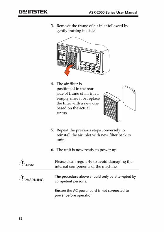
3. Remove the frame of air inlet followed by gently putting it aside.
4. The air filter is positioned in the rear side of frame of air inlet. Simply rinse it or replace the filter with a new one based on the actual status.
5. Repeat the previous steps conversely to reinstall the air inlet with new filter back to unit.
6. The unit is now ready to power up.
Note Please clean regularly to avoid damaging the internal components of the machine.
WARNING The procedure above should only be attempted by competent persons.
Ensure the AC power cord is not connected to power before operation.
OPERATION
53
Wire Gauge Considerations
Background Before connecting the output terminals to a load, the wire gauge of the cables should be considered.
It is essential that the current capacity of the load cables is adequate. The rating of the cables must equal or exceed the maximum current rated output of the instrument.
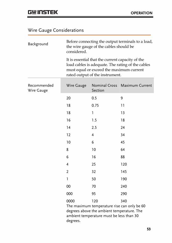
Recommended Wire Gauge
Wire Gauge Nominal Cross Section
Maximum Current
20 0.5 9
18 0.75 11
18 1 13
16 1.5 18
14 2.5 24
12 4 34
10 6 45
8 10 64
6 16 88
4 25 120
2 32 145
1 50 190
00 70 240
000 95 290
0000 120 340 The maximum temperature rise can only be 60
degrees above the ambient temperature. The ambient temperature must be less than 30 degrees.

ASR-2000 Series User Manual
54
To minimize noise pickup or radiation, the load wires and remote sense wires should be twisted-pairs of the shortest possible length. Shielding of the sense leads may be necessary in high noise environments. Where shielding is used, connect the shield to the chassis via the rear panel ground screw. Even if noise is not a concern, the load and remote sense wires should be twisted-pairs to reduce coupling, which might impact the stability of the power supply. The sense leads should be separated from the power leads.
OPERATION
55
Menu Tree
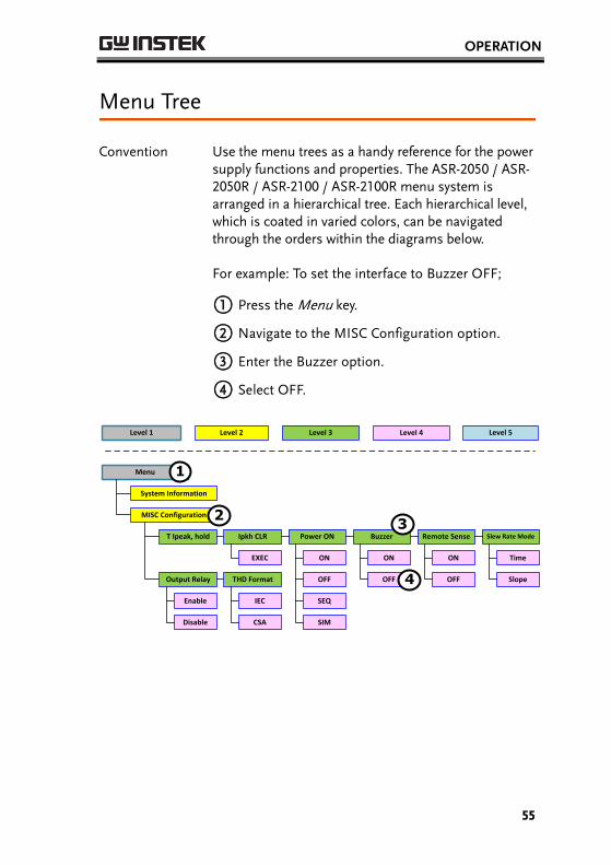
Convention Use the menu trees as a handy reference for the power supply functions and properties. The ASR-2050 / ASR-2050R / ASR-2100 / ASR-2100R menu system is arranged in a hierarchical tree. Each hierarchical level, which is coated in varied colors, can be navigated through the orders within the diagrams below.
For example: To set the interface to Buzzer OFF;
○1 Press the Menu key.
○2 Navigate to the MISC Configuration option.
○3 Enter the Buzzer option.
○4 Select OFF.
Menu
System Information
MISC Configuration
T Ipeak, hold
Level 2Level 1 Level 3
Ipkh CLR
EXEC
Level 4
Power ON Buzzer Remote Sense Slew Rate Mode
ON
OFF
Time
Slope
ON
OFF
ON
OFF
SEQ
SIM
Output Relay
Enable
Disable
THD Format
IEC
CSA
1
23
4
Level 5

ASR-2000 Series User Manual
56
Main Page
Main Page
MODE
AC+DC-INT
ACV DCV FREQ IRMS ON phs WAVE Test
FIXED
FREE
SIN
SQU
TRI
ARB 1~16
SEQ
AC-INT
ACV FREQ IRMS WAVE Test
FIXED
FREE
SIN
SQU
TRI
ARB 1~16
SEQ
SIM
DC-INT
DCV I Test
SEQ
AC+DC-EXT
GAIN IRMS
AC-EXT
GAIN IRMS
AC+DC-ADD
ACV DCV FREQ IRMS ON phs WAVE
FIXED
FREE
SIN SQU
TRI ARB 1~16
GAIN
AC-ADD
ACV FREQ IRMS WAVE
FIXED
FREE
SIN
GAIN
SQU
TRI ARB 1~16
AC+DC-sync
ACV DCV SIG IRMS
AC-sync
ACV FREQ IRMS
LINE
EXT
LINE
EXT
OFF phs
FIXED
FREE
ON phs OFF phs
FIXED
FREE
OFF phs
FIXED
FREE
ON phs OFF phs
FIXED
FREE
WAVE
FIXED
FREE
SIN SQU
TRI ARB 1~16
ON phs OFF phs
FIXED
FREE
WAVE
FIXED
FREE
SIN SQU
TRI ARB 1~16
ON phs OFF phs
FIXED
FREE
OPERATION
57
Function Keys
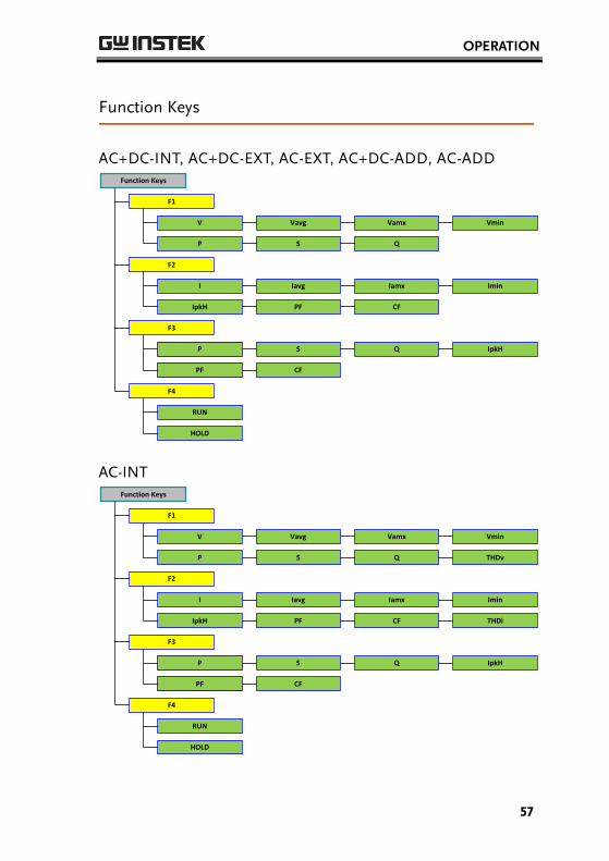
AC+DC-INT, AC+DC-EXT, AC-EXT, AC+DC-ADD, AC-ADD Function Keys
F1
V Vavg Vamx Vmin
P S Q
F2
I Iavg Iamx Imin
IpkH PF CF
F3
P S Q IpkH
PF CF
RUN
HOLD
F4
AC-INT Function Keys
F1
V Vavg Vamx Vmin
P S Q
F2
I Iavg Iamx Imin
IpkH PF CF
THDv
THDi
F3
P S Q IpkH
PF CF
RUN
HOLD
F4
ASR-2000 Series User Manual
58
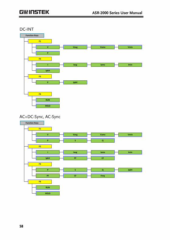
DC-INT Function Keys
F1
V Vavg Vamx Vmin
P
F2
I Iavg Iamx Imin
IpkH
F3
P IpkH
RUN
HOLD
F4
AC+DC-Sync, AC-Sync Function Keys
F1
V Vavg Vamx Vmin
P S Q
F2
I Iavg Iamx Imin
IpkH PF CF
F3
P S Q IpkH
PF CF Freq
RUN
HOLD
F4
OPERATION
59
Menu
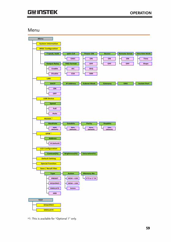
Menu
System Information
MISC Configuration
T Ipeak, hold Ipkh CLR
EXEC
Power ON Buzzer Remote Sense Slew Rate Mode
ON
OFF
Time
Slope
ON
OFF
ON
OFF
SEQ
SIM
Output Relay
Enable
Disable
THD Format
IEC
CSA
LAN
DHCP IP Address Subnet Mask Gateway DNS Socket Port
ON
OFF
USB Device
Speed
Full
Auto
RS232C*1
Baudrate Databits Parity Stopbits
9600 (default)
8bits (default)
None (default)
1bits (default)
GPIB*1
Address
10 (default)
LCD Configuration
Contrast(%) Brightness(%) Saturation(%)
Default Setting
Special Function
Save / Recall Files
Type Action Memory No.
PRESET MEM→USB 0~9 or 1~16
SEQUENCE
SIMULATE
ARB
MEM←USB
Delete
TEST
SEQUENCE
SIMULATE
*1: This is available for “Optional 1” only.

ASR-2000 Series User Manual
60
Basic Operation This section describes the basic operations required to operate the power supply.
Select the Output Mode → from page 61
Select the Voltage Range → from page 62
Select the Output Waveform → from page 63
Setting the Output Voltage Limit → from page 65
Setting the Output AC/DC Voltage & Gain → from page 68
Setting the Frequency Limit → from page 71
Setting the Output Frequency & Signal → from page 74
Setting the Peak Current Limit → from page 76
Setting the Output Current Level → from page 79
Setting the Output On Phase → page 82
Setting the Output Off Phase → page 84
Switch the Display Modes → from page 86
Using the Measurement Function → from page 89
Switch the Measurement Format → from page 92
Panel Lock → from page 94
Alarm Clear → from page 95
Turning the Output On/Off → from page 96
Before operating the power supply, please see the Getting Started chapter, page 9.
OPERATION
61
Select the Output Mode
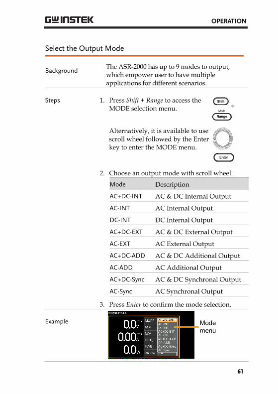
Background The ASR-2000 has up to 9 modes to output, which empower user to have multiple applications for different scenarios.
Steps 1. Press Shift + Range to access the MODE selection menu. +
Alternatively, it is available to use scroll wheel followed by the Enter key to enter the MODE menu.
2. Choose an output mode with scroll wheel.
Mode Description
AC+DC-INT AC & DC Internal Output
AC-INT AC Internal Output
DC-INT DC Internal Output
AC+DC-EXT AC & DC External Output
AC-EXT AC External Output
AC+DC-ADD AC & DC Additional Output
AC-ADD AC Additional Output
AC+DC-Sync AC & DC Synchronal Output
AC-Sync AC Synchronal Output
3. Press Enter to confirm the mode selection.
Example
Modemenu

ASR-2000 Series User Manual
62
Select the Voltage Range
Background The Range setting determines the general outlet voltage range. The ranges available correspond to common mains output voltage standards.
Steps 1. Press Range to access the Range menu.
2. Set the voltage range with the F1 ~ F4 soft-keys.
Soft-keys
F1: AUTO
F3: 200V
F4: 100V
3. Press Enter to confirm the Range setting.
Example
Range setting
F1
F3
F4
Note The output voltage values set by user can be divided into 2 manual settings, both of which have close relation with voltage range that contains high range (200V, AUTO) and low range (100V). For instance, when setting 5 Vrms under 200V range and 3 Vrms under 100V range, the Vrms setting will change from 5 Vrms to 3 Vrms directly after switching the voltage range from 200V to 100V.
Also, if the voltage range is changed when the output is on, the output will be automatically turned off.
OPERATION
63
Select the Output Waveform
Background The ASR-2000 is capable of outputting sine, square, triangle and ARB wave shapes while connecting with external signals.
Steps 1. Press Shift + Test to access the Wave menu. +
Alternatively, it is available to use scroll wheel followed by the Enter key to enter the Wave menu.
2. Choose a waveform with scroll wheel.
Mode Description
SIN Sine wave
SQU Square wave
TRI Triangle wave
ARB 1 ~ 16 Arbitrary wave 1 ~ 16
3. Press Enter to confirm the waveform setting.

ASR-2000 Series User Manual
64
Wavesetting
Note Waveform selection is Not available under DC-
INT, AC+DC-EXT and AC-EXT output modes.
For more details about Arbitrary waveforms, refer to the page 110.
When changing to a waveform with setting higher than the upper limit of other waveform, the setting of other waveform will be adjusted to zero forcibly. For instance, when it is originally SIN output with ACV in 150 Vrms (175 Vrms for V-Limit), the ACV will be changed to 0 Vrms (144.3 Vrms for V-Limit) after output waveform adjusts to TRI.
OPERATION
65
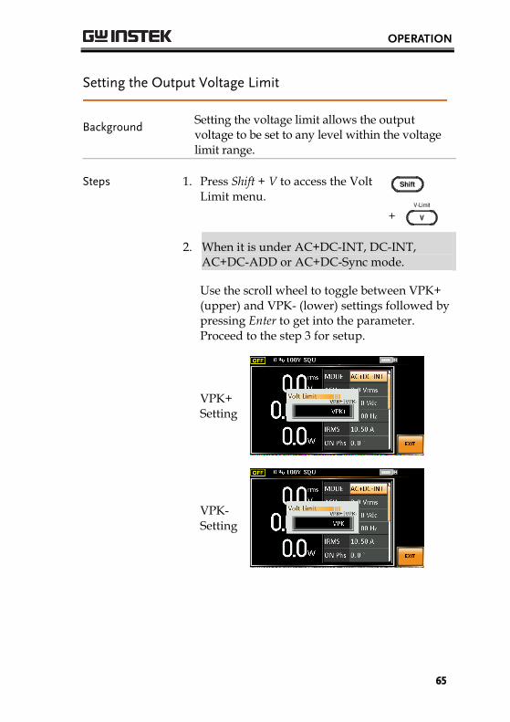
Setting the Output Voltage Limit
Background Setting the voltage limit allows the output voltage to be set to any level within the voltage limit range.
Steps 1. Press Shift + V to access the Volt Limit menu.
+
2. When it is under AC+DC-INT, DC-INT,
AC+DC-ADD or AC+DC-Sync mode.
Use the scroll wheel to toggle between VPK+ (upper) and VPK- (lower) settings followed by pressing Enter to get into the parameter. Proceed to the step 3 for setup.
VPK+ Setting
VPK- Setting

ASR-2000 Series User Manual
66
When it is under AC-INT, AC-ADD or AC-Sync mode.
Use the scroll wheel to set value of Vrms limit directly or use the F3 (MAX) and F4 (MIN) soft-keys to set the limit to the maximum or minimum value.
AC–INT, AC-ADD, AC-Sync
Vrms
Range 10% ~ 100% full range voltage
Soft-keys MAX, MIN
Vrms Setting
Note The Vrms Limit value defined by user will be generally applied to AC-INT, AC-ADD and AC-Sync modes under the same voltage range, which divides into 2 levels, high range including AUTO and 200V and low range covering 100V.
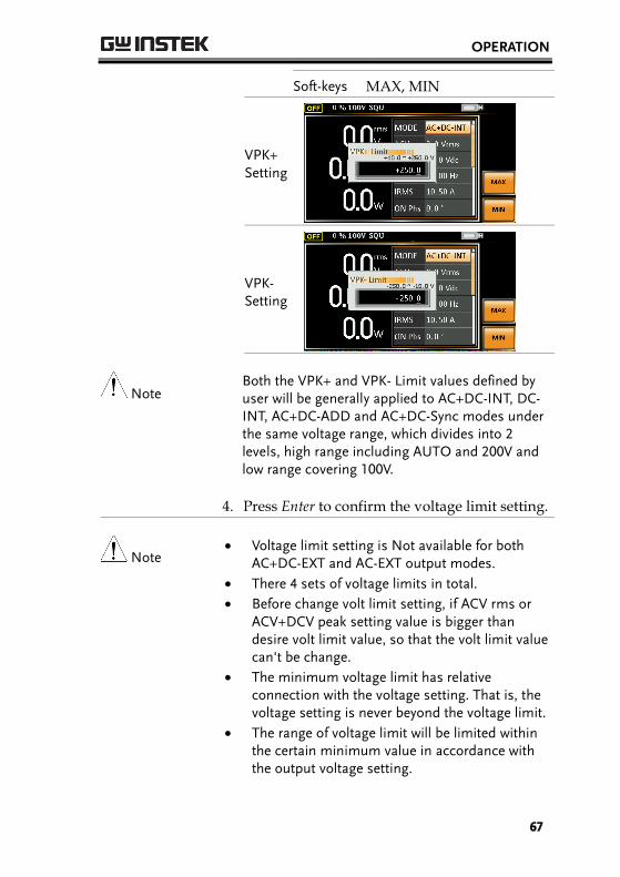
3. Set the voltage limit (VPK+ & VPK-) with the scroll wheel or with the F3 (MAX) and F4 (MIN) soft-keys to set the limit to the maximum and minimum values, respectively.
AC+DC-INT, DC-INT,
AC+DC-ADD, AC+DC-Sync
VPK+
Range 4% ~ 100% full range peak voltage
Soft-keys MAX, MIN
VPK-
Range 4% ~ 100% full range peak voltage
OPERATION
67
Soft-keys MAX, MIN
VPK+ Setting
VPK- Setting
Note Both the VPK+ and VPK- Limit values defined by user will be generally applied to AC+DC-INT, DC-INT, AC+DC-ADD and AC+DC-Sync modes under the same voltage range, which divides into 2 levels, high range including AUTO and 200V and low range covering 100V.
4. Press Enter to confirm the voltage limit setting.
Note Voltage limit setting is Not available for both
AC+DC-EXT and AC-EXT output modes.
There 4 sets of voltage limits in total.
Before change volt limit setting, if ACV rms or ACV+DCV peak setting value is bigger than desire volt limit value, so that the volt limit value can't be change.
The minimum voltage limit has relative connection with the voltage setting. That is, the voltage setting is never beyond the voltage limit.
The range of voltage limit will be limited within the certain minimum value in accordance with the output voltage setting.

ASR-2000 Series User Manual
68
Setting the Output AC/DC Voltage & Gain
Background The ACV, DCV and Gain settings set the output voltage level. Before setting the power supply voltage level, set the voltage range and voltage limit beforehand.
Steps 1. Press the V key. The ACV parameter will be selectable.
Also, it is available to use the scroll wheel followed by the Enter key to make the ACV parameter selectable as well.
DCV
When it is under AC+DC-INT, AC+DC-ADD or AC+DC-Sync mode.
Further use the scroll wheel to navigate to the DCV parameter and press Enter to make DCV parameter selectable.
When it is under DC-INT mode.
Directly press the V key or use the scroll wheel to navigate to the DCV parameter and press Enter to make DCV parameter selectable.
GAIN
When it is under AC+DC-EXT or AC-EXT mode.
Directly press the V key or use the scroll wheel to navigate to the GAIN parameter and press Enter to make GAIN parameter selectable.
When it is under AC-ADD mode.
Further use the scroll wheel to navigate to the GAIN parameter and press Enter to make GAIN parameter selectable.
OPERATION
69
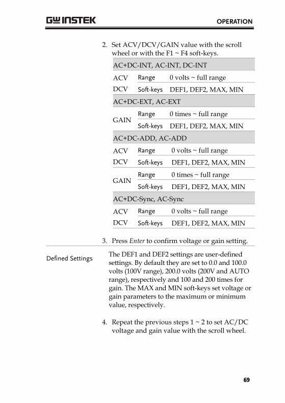
2. Set ACV/DCV/GAIN value with the scroll wheel or with the F1 ~ F4 soft-keys.
AC+DC-INT, AC-INT, DC-INT
ACV
DCV
Range 0 volts ~ full range
Soft-keys DEF1, DEF2, MAX, MIN
AC+DC-EXT, AC-EXT
GAIN
Range 0 times ~ full range
Soft-keys DEF1, DEF2, MAX, MIN
AC+DC-ADD, AC-ADD
ACV
DCV
Range 0 volts ~ full range
Soft-keys DEF1, DEF2, MAX, MIN
GAIN
Range 0 times ~ full range
Soft-keys DEF1, DEF2, MAX, MIN
AC+DC-Sync, AC-Sync
ACV
DCV
Range 0 volts ~ full range
Soft-keys DEF1, DEF2, MAX, MIN
3. Press Enter to confirm voltage or gain setting.
Defined Settings The DEF1 and DEF2 settings are user-defined settings. By default they are set to 0.0 and 100.0 volts (100V range), 200.0 volts (200V and AUTO range), respectively and 100 and 200 times for gain. The MAX and MIN soft-keys set voltage or gain parameters to the maximum or minimum value, respectively.
4. Repeat the previous steps 1 ~ 2 to set AC/DC voltage and gain value with the scroll wheel.

ASR-2000 Series User Manual
70
5. Press and hold either the DEF1 or DEF2 soft-key until “Saved to DEF1/2” is displayed, which indicates the voltage and gain settings are saved to the DEF1 or DEF2 soft-key individually.
Note Trying to set the voltage outside of the voltage
limit/range will result in a voltage setting error being displayed on the screen.
ACV, DCV and GAIN settings under each output mode and range have their own DEF1 and DEF2 saved values, respectively.
Example of ACV Setting in the AC+DC-INT
ACV setting Defined setting
F3
F4
F1
F2
Example of DCV Setting in the DC-INT
DCV setting Defined setting
F3
F4
F1
F2
Example of GAIN Setting in the AC+DC-EXT
GAIN setting Defined setting
F3
F4
F1
F2

OPERATION
71
Setting the Frequency Limit
Background Setting the frequency limit allows the frequency output to be set to any level within the limit range.
Steps 1. Press Shift + F to access the Freq Limit menu.
+
2. Use the scroll wheel to toggle between Freq Hi (upper) and Freq Lo (lower) settings followed by pressing Enter to get into the parameter.
Freq Hi Setting
Freq Lo Setting
3. Set the frequency limit with the scroll wheel or with the F3 ~ F4 soft-keys. The MAX and MIN soft-keys set the frequency limit to the maximum and minimum, respectively.

ASR-2000 Series User Manual
72
AC+DC-INT, AC+DC-ADD
Freq Hi Limit
Range 1.00 ~ 999.9 Hz
Soft-keys MAX, MIN
Freq Lo Limit
Range 1.00 ~ 999.9 Hz
Soft-keys MAX, MIN
Freq Hi Setting
Freq Lo Setting
AC-INT, AC-ADD
Freq Hi Limit
Range 40.00 ~ 999.9 Hz
Soft-keys MAX, MIN
Freq Lo Limit
Range 40.00 ~ 999.9 Hz
Soft-keys MAX, MIN
Freq Hi Setting

OPERATION
73
Freq Lo Setting
4. Press Enter to confirm the limit setting.
Example of Freq Hi Limit Setting in AC+DC-INT
Freq Limit setting
Min/Max settings
F3
F4
Note Frequency limit setting is Not available under
DC-INT, AC+DC-EXT, AC-EXT, AC+DC-Sync and AC-Sync output modes.
Before change freq limit setting, if FREQ setting value is bigger than desire freq limit value, the freq limit value cannot be change accordingly.
The range of frequency limit will be limited within the certain minimum value in accordance with the output frequency setting.
There are 2 sets of frequency limits in total.
ASR-2000 Series User Manual
74
Setting the Output Frequency & Signal
Background The FREQ and SIN settings set the frequency of the output. Before setting the frequency, set the frequency limit.
Steps 1. Press the F key to access the FREQ or SIG parameter depending on varied modes.
Also, it is available to use the scroll wheel followed by the Enter key to make the FREQ or SIG parameter selectable as well.
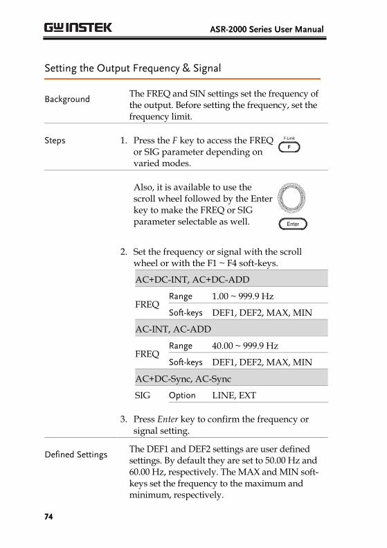
2. Set the frequency or signal with the scroll wheel or with the F1 ~ F4 soft-keys.
AC+DC-INT, AC+DC-ADD
FREQ
Range 1.00 ~ 999.9 Hz
Soft-keys DEF1, DEF2, MAX, MIN
AC-INT, AC-ADD
FREQ
Range 40.00 ~ 999.9 Hz
Soft-keys DEF1, DEF2, MAX, MIN
AC+DC-Sync, AC-Sync
SIG Option LINE, EXT
3. Press Enter key to confirm the frequency or signal setting.
Defined Settings The DEF1 and DEF2 settings are user defined settings. By default they are set to 50.00 Hz and 60.00 Hz, respectively. The MAX and MIN soft-keys set the frequency to the maximum and minimum, respectively.
OPERATION
75
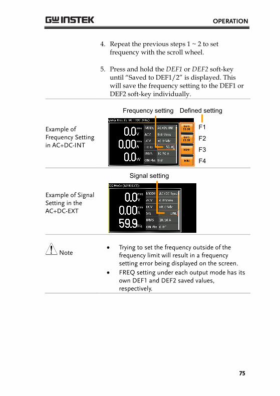
4. Repeat the previous steps 1 ~ 2 to set frequency with the scroll wheel.
5. Press and hold the DEF1 or DEF2 soft-key until “Saved to DEF1/2” is displayed. This will save the frequency setting to the DEF1 or DEF2 soft-key individually.
Example of Frequency Setting in AC+DC-INT
Frequency setting Defined setting
F3
F4
F1
F2
Example of Signal Setting in the AC+DC-EXT
Signal setting
Note Trying to set the frequency outside of the
frequency limit will result in a frequency setting error being displayed on the screen.
FREQ setting under each output mode has its own DEF1 and DEF2 saved values, respectively.
ASR-2000 Series User Manual
76
Setting the Peak Current Limit
Background Setting the peak current limit sets a limit on the current that can be sourced by the power supply. Once the output current over the setting, the output will set to off.
Note When the peak current limit is tripped, an alarm will sound. Press Shift + Cancel to clear the Ipk alarm.
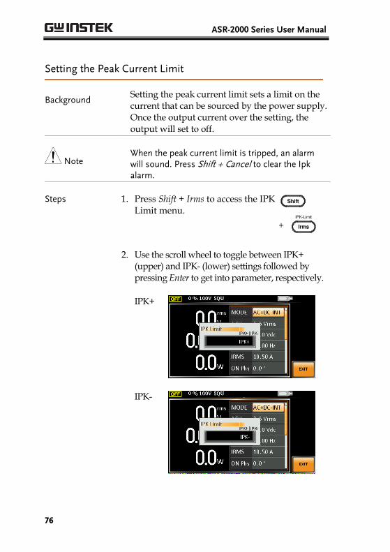
Steps 1. Press Shift + Irms to access the IPK Limit menu.
+
2. Use the scroll wheel to toggle between IPK+ (upper) and IPK- (lower) settings followed by pressing Enter to get into parameter, respectively.
IPK+
IPK-
OPERATION
77
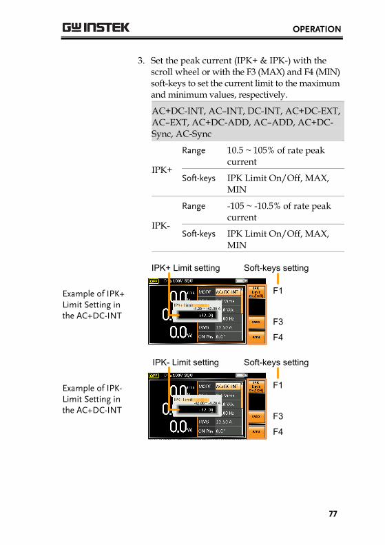
3. Set the peak current (IPK+ & IPK-) with the scroll wheel or with the F3 (MAX) and F4 (MIN) soft-keys to set the current limit to the maximum and minimum values, respectively.
AC+DC-INT, AC–INT, DC-INT, AC+DC-EXT, AC–EXT, AC+DC-ADD, AC–ADD, AC+DC-Sync, AC-Sync
IPK+
Range 10.5 ~ 105% of rate peak current
Soft-keys IPK Limit On/Off, MAX, MIN
IPK-
Range -105 ~ -10.5% of rate peak current
Soft-keys IPK Limit On/Off, MAX, MIN
Example of IPK+ Limit Setting in the AC+DC-INT
IPK+ Limit setting Soft-keys setting
F3
F4
F1
Example of IPK- Limit Setting in the AC+DC-INT
IPK- Limit setting Soft-keys setting
F3
F4
F1

ASR-2000 Series User Manual
78
IPK Limit On/Off
In theory, It is the function which keeps the IPK limits (+ & -) within the certain range when the predefined values are reached. If, however, this function is turned off, the output will be disabled instantly when either IPK+ or IPK- limit is reached.
IPK Limit On 4. After entering the either IPK+ Limit or IPK- Limit setting, press F1 soft key to turn IPK Limit function On.
IPK Limit ON:
T
Kept within IPK Limit On Level
I
Load On
IPK Limit Off 5. After entering the either IPK+ Limit or IPK- Limit setting, press F1 soft key to turn IPK Limit function Off.
IPK Limit OFF:
T
IPK Limit Off Level is reached.Turn the Output Off Immediately.
I
Load On
6. Press Enter to confirm the peak current setting.
OPERATION
79
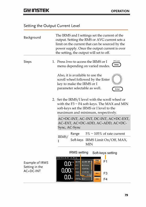
Setting the Output Current Level
Background The IRMS and I settings set the current of the output. Setting the RMS or AVG current sets a limit on the current that can be sourced by the power supply. Once the output current is over the setting, the output will set to off.
Steps 1. Press Irms to access the IRMS or I menu depending on varied modes.
Also, it is available to use the scroll wheel followed by the Enter key to make the IRMS or I parameter selectable as well.
2. Set the IRMS/I level with the scroll wheel or with the F3 ~ F4 soft-keys. The MAX and MIN soft-keys set the IRMS or I level to the maximum and minimum, respectively.
AC+DC-INT, AC–INT, DC-INT, AC+DC-EXT, AC–EXT, AC+DC-ADD, AC–ADD, AC+DC-Sync, AC-Sync
IRMS/I
Range 5% ~ 105% of rate current
Soft-keys IRMS Limit On/Off, MAX, MIN
Example of IRMS Setting in the AC+DC-INT
IRMS setting Soft-keys setting
F3
F4
F1

ASR-2000 Series User Manual
80
Example of I Setting in the DC-INT
I setting Soft-keys setting
F3
F4
F1
IRMS & I Limit On/Off
Almost identical with the concept of previous IPK Limit function, the IRMS/I Limit function keeps the IRMS/I value within the certain limit when the predefined value is reached. However, due to RMS calculation, the unit requires approximate 200ms of detect time before starting the adjustment process so that the IRMS/I limit can be well maintained. If, on the other hand, this function is turned off, the output will be disabled instantly when IRMS/I Limit off level is reached.
IRMS & I Limit On
3. After entering the either IRMS or I setting, press F1 soft key to turn IRMS Limit function On.
IRMS & I Limit ON:
T
Kept within IRMS & I Limit On Level
I
Detect TimeApprox. 200ms
AdjustmentprocessLoad On

OPERATION
81
IRMS & I Limit Off
4. After entering the either IRMS or Isetting, press F1 soft key to turnIRMS Limit function Off.
IRMS & I Limit OFF:
T
IRMS or I Limit Off Level is reached.Turn the Output Off Immediately.
I
Load On
5. Press Enter to confirm the IRMS/I setting.

ASR-2000 Series User Manual
82
Setting the Output On Phase
Background
The on phase setting sets the starting phase of the voltage output.
Steps 1. Press Shift + Menu to make the ON Phs parameter selectable.
+
Also, it is available to use the scroll wheel followed by the Enter key to make the ON Phs parameter selectable as well.
2. Set the ON Phs setting with the scroll wheel or with the F3 (MAX) and F4 (MIN) soft-keys to set the On Phase to the maximum and minimum values, respectively.
AC+DC-INT, AC-INT, AC+DC-ADD,
AC-ADD, AC+DC-Sync, AC-Sync
ON Phs
Range 0.0° ~ 359.9°
Soft-keys FIXED/FREE, MAX, MIN
3. Press Enter to confirm the On Phase setting.
OPERATION
83
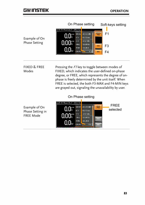
Example of On Phase Setting
On Phase setting
F1
F3
F4
Soft-keys setting
FIXED & FREE Modes
Pressing the F1 key to toggle between modes of FIXED, which indicates the user-defined on-phase degree, or FREE, which represents the degree of on-phase is freely determined by the unit itself. When FREE is selected, the both F3-MAX and F4-MIN keys are grayed out, signaling the unavailability by user.
Example of On Phase Setting in FREE Mode
On Phase setting
FREEselected

ASR-2000 Series User Manual
84
Setting the Output Off Phase
Background
The off phase setting sets the ending phase of the voltage output.
Steps 1. Use the scroll wheel followed by the Enter key to make the OFF Phs parameter selectable.
2. Set the OFF Phs setting with the scroll wheel or with the F3 (MAX) and F4 (MIN) soft-keys to set the Off Phase to the maximum and minimum values, respectively.
AC+DC-INT, AC-INT, AC+DC-ADD,
AC-ADD, AC+DC-Sync, AC-Sync
OFF Phs
Range 0.0° ~ 359.9°
Soft-keys FIXED/FREE, MAX, MIN
3. Press Enter to confirm the Off Phase setting.

OPERATION
85
Example of OFF Phase Setting
OFF Phase setting
F1
F3
F4
Soft-keys setting
FIXED & FREE Modes
Pressing the F1 key to toggle between modes of FIXED, which indicates the user-defined off-phase degree, or FREE, which represents the degree of off-phase is freely determined by the unit itself. When FREE is selected, the both F3-MAX and F4-MIN keys are grayed out, signaling the unavailability by user.
Example of OFF Phase Setting in FREE Mode
OFF Phase setting
FREEselected
ASR-2000 Series User Manual
86
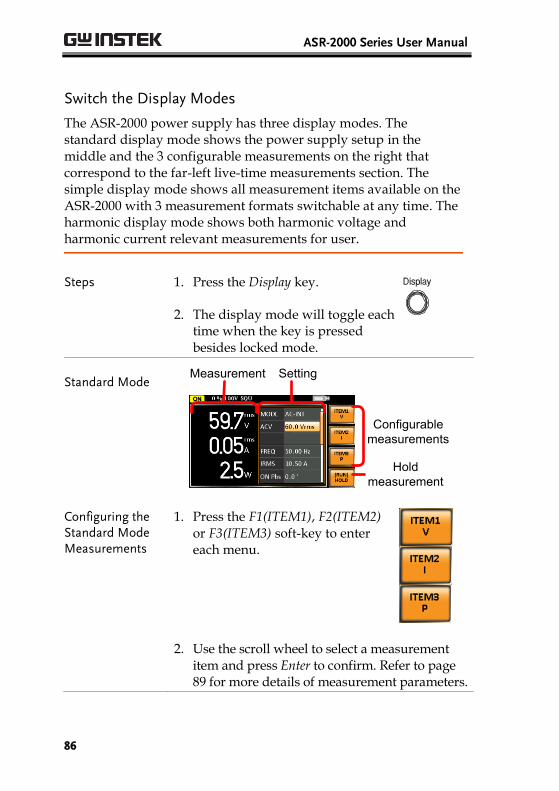
Switch the Display Modes
The ASR-2000 power supply has three display modes. The standard display mode shows the power supply setup in the middle and the 3 configurable measurements on the right that correspond to the far-left live-time measurements section. The simple display mode shows all measurement items available on the ASR-2000 with 3 measurement formats switchable at any time. The harmonic display mode shows both harmonic voltage and harmonic current relevant measurements for user.
Steps 1. Press the Display key.
2. The display mode will toggle eachtime when the key is pressedbesides locked mode.
Standard Mode Measurement Setting
Configurable measurements
Hold measurement
Configuring the Standard Mode Measurements
1. Press the F1(ITEM1), F2(ITEM2)or F3(ITEM3) soft-key to entereach menu.
2. Use the scroll wheel to select a measurementitem and press Enter to confirm. Refer to page89 for more details of measurement parameters.
OPERATION
87
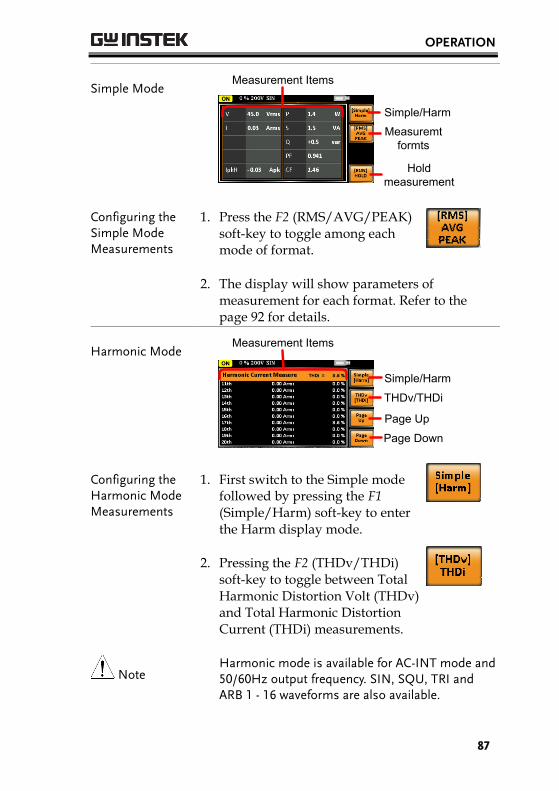
Simple Mode Measurement Items
Hold measurement
Measuremt formts
Simple/Harm
Configuring the Simple Mode Measurements
1. Press the F2 (RMS/AVG/PEAK) soft-key to toggle among each mode of format.
2. The display will show parameters of measurement for each format. Refer to the page 92 for details.
Harmonic Mode
Measurement Items
Page Down
Page Up
THDv/THDi
Simple/Harm
Configuring the Harmonic Mode Measurements
1. First switch to the Simple mode followed by pressing the F1 (Simple/Harm) soft-key to enter the Harm display mode.
2. Pressing the F2 (THDv/THDi) soft-key to toggle between Total Harmonic Distortion Volt (THDv) and Total Harmonic Distortion Current (THDi) measurements.
Note Harmonic mode is available for AC-INT mode and 50/60Hz output frequency. SIN, SQU, TRI and ARB 1 - 16 waveforms are also available.

ASR-2000 Series User Manual
88
3. When the measurements are beyond one page, which consists of up to 10 items, press the F3 (Page Up) and F4 (Page Down) soft-keys to flip through pages.
Hold Measurement
Press the soft-key F4 to toggle hold on or off. This function will “hold” the current measurements on the display, which means the measurements won’t be updated until the function is released.
Note Hold measurement is available for the Standard and Simple display modes only.
OPERATION
89
Using the Measurement Function
The 3 configurable measurements, which indicate the live-time measurement in varied units, on the far-right side within the standard display mode can be switched by user anytime in the process of power output, thus providing an instantaneous analysis.
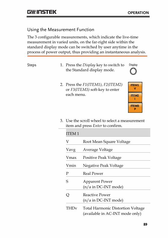
Steps 1. Press the Display key to switch tothe Standard display mode.
2. Press the F1(ITEM1), F2(ITEM2)or F3(ITEM3) soft-key to entereach menu.
3. Use the scroll wheel to select a measurement item and press Enter to confirm.
ITEM 1
V Root Mean Square Voltage
Vavg Average Voltage
Vmax Positive Peak Voltage
Vmin Negative Peak Voltage
P Real Power
S Apparent Power
(n/a in DC-INT mode)
Q Reactive Power
(n/a in DC-INT mode)
THDv Total Harmonic Distortion Voltage
(available in AC-INT mode only)
ASR-2000 Series User Manual
90
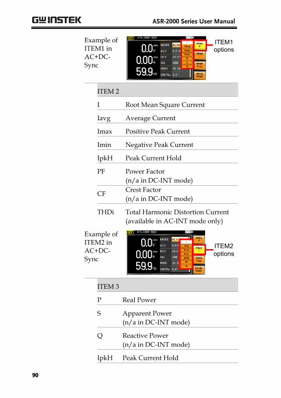
Example of ITEM1 in AC+DC-Sync
ITEM1options
ITEM 2
I Root Mean Square Current
Iavg Average Current
Imax Positive Peak Current
Imin Negative Peak Current
IpkH Peak Current Hold
PF Power Factor
(n/a in DC-INT mode)
CF Crest Factor
(n/a in DC-INT mode)
THDi Total Harmonic Distortion Current
(available in AC-INT mode only)
Example of ITEM2 in AC+DC-Sync
ITEM2options
ITEM 3
P Real Power
S Apparent Power
(n/a in DC-INT mode)
Q Reactive Power
(n/a in DC-INT mode)
IpkH Peak Current Hold

OPERATION
91
PF Power Factor
(n/a in DC-INT mode)
CF Crest Factor
(n/a in DC-INT mode)
Freq Frequency
(available in AC+DC-Sync and AC-Sync modes only)
Example of ITEM3 in AC+DC-Sync
ITEM3options
Note Each output mode has varied measurement functions display. Refer to the above tables for detailed options.
ASR-2000 Series User Manual
92
Switch the Measurement Format
The 3 measuring formats, RMS, AVG as well as PEAK, on the far-right side within the simple display mode can be switched by user anytime in the process of power output, thus offering an instant readout of diversified calculations.
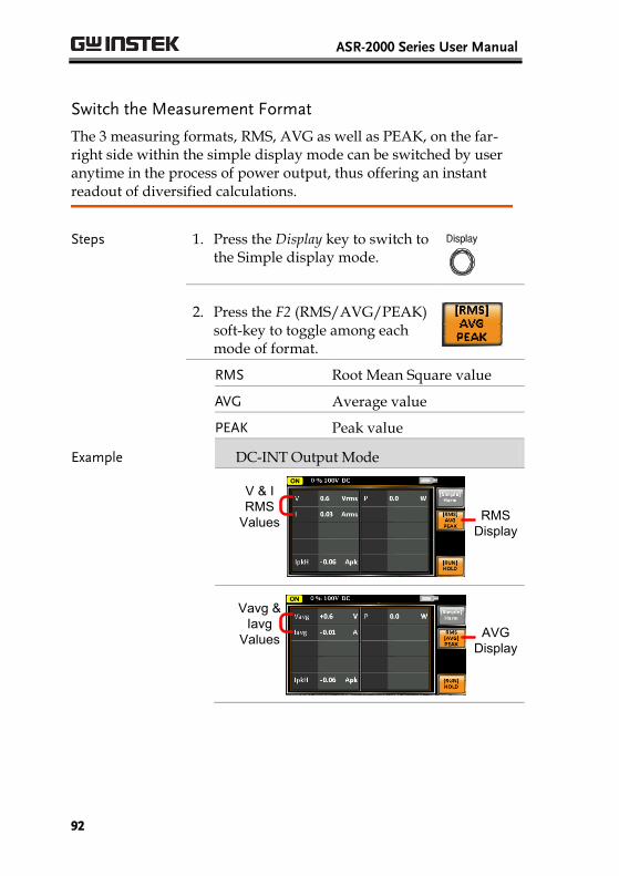
Steps 1. Press the Display key to switch to the Simple display mode.
2. Press the F2 (RMS/AVG/PEAK) soft-key to toggle among each mode of format.
RMS Root Mean Square value
AVG Average value
PEAK Peak value
Example DC-INT Output Mode
RMSDisplay
V & IRMS
Values
AVGDisplay
Vavg & Iavg
Values

OPERATION
93
PEAKDisplay
Vmax/Vmin
& Imax/Imin
Values
All output modes except DC-INT
RMSDisplay
V & IRMS
Values
AVGDisplay
Vavg & Iavg
Values
PEAKDisplay
Vmax/Vmin
& Imax/Imin
Values
Note The selected measurement format will be merely shown in the Simple display mode, for which refer to page 87 for further details.

ASR-2000 Series User Manual
94
Panel Lock
The panel lock feature prevents settings from being changed accidentally. When activated, all keys and knobs except the Lock/Unlock key and the Output key (if active) will be disabled.
If the instrument is remotely controlled via the USB/LAN/RS-232/GPIB interface, the panel lock is automatically enabled. See page 159 for remote control details.
Activate the
Panel Lock
Press the Lock key to active the panel lock. “Keys locked” appears on the display.
A lock icon will appear in the upper-right corner when the panel keys are locked.
Disable the
Panel Lock
Hold the Lock key for ~3 seconds to disable the panel lock. “Keys unlocked” will appear on the display and the lock icon will disappear.
Example
Message Lock icon

OPERATION
95
Alarm Clear
Background
The ALM CLR (Alarm Clear) function will clear alarms like Over Current, Over Peak Current, Over Temperature, AC fail, Fan fail, Remote Sense Error, among others. Refer to page 187 for more details.
Steps 1. Press Shift + Cancel to clear any alarms.
+
Example
Alarm message
ALM indicator

ASR-2000 Series User Manual
96
Turning the Output On/Off
When the output is turned on, the DUT can be connected to either the rear panel output or the front panel output.
WARNING Both of these outputs are electrically linked. Only one DUT should be connected to any one of the outputs at a time. Using both outputs at the same time is not supported. Using the front and rear outputs at the same time could cause dangerous operating conditions. See page 38 for details about using the output terminals or sockets.
Turn Output On Press the Output key. The Output key will light up in orange and ON will be displayed in the status bar to indicate that the output is on.
Turn Output Off Press the Output key. The Output key light will go out and OFF will be displayed in the status bar to indicate that the output is off.

OPERATION
97
Advanced Settings
Using the Remote Sense Function → from page 97
Preset Settings → from page 100
Using the Remote Sense Function
The ASR-2000 can be operated using local or remote voltage sense. By default, the power supply is configured for local sense.
WARNING Ensure the output is off before handling the remote sense connectors.
Use sense cables with a voltage rating exceeding the isolation voltage of the power supply.
Never connect sensing cables when the output is on. Electric shock or damage to the power supply could result.
Remote Sensing Input Connectors Overview
The remote sensing input connector is located at the rear panel of the ASR-2000.
Local Sense
Local Sense Operation
When using local sense, the remote sensing input terminal is not used. No compensation of any possible voltage drop seen on the load cables is performed. Local sense is only recommended when the voltage drop is of no consequence. By default, the power supply is configured for local sense.
1. Check that the remote sense setting is disabled (page 121).

ASR-2000 Series User Manual
98
Remote Sense
Remote Sense Operation
Remote sense is used to compensate for the voltage drop seen across load cables due to resistance inherent in the load cables. The remote sense function can compensate a maximum of 5% of the output voltage and all of output frequency.
1. Configure the remote sense setting to ON(page 121).
2. Connect the Neutral terminal of the remotesense terminal block to the Neutral terminal ofthe load.
3. Connect the Live terminal of the remote senseterminal block to the Live terminal of the load.
Connection Example
OUTPUT terminal block
Load cables
Sensing points
Sensing cables
N.C. terminals are Not available in the case.
Load
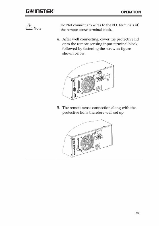
OPERATION
99
Note Do Not connect any wires to the N.C terminals of the remote sense terminal block.
4. After well connecting, cover the protective lid onto the remote sensing input terminal block followed by fastening the screw as figure shown below.
5. The remote sense connection along with the protective lid is therefore well set up.
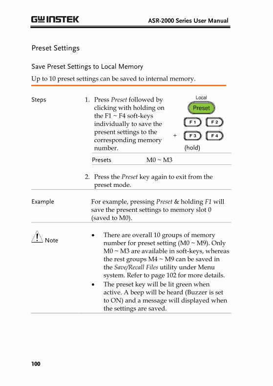
ASR-2000 Series User Manual
100
Preset Settings
Save Preset Settings to Local Memory
Up to 10 preset settings can be saved to internal memory.
Steps 1. Press Preset followed byclicking with holding on the F1 ~ F4 soft-keys individually to save the present settings to the corresponding memory number.
+
(hold)
Presets M0 ~ M3
2. Press the Preset key again to exit from thepreset mode.
Example For example, pressing Preset & holding F1 will save the present settings to memory slot 0 (saved to M0).
Note There are overall 10 groups of memory
number for preset setting (M0 ~ M9). OnlyM0 ~ M3 are available in soft-keys, whereasthe rest groups M4 ~ M9 can be saved inthe Save/Recall Files utility under Menusystem. Refer to page 102 for more details.
The preset key will be lit green whenactive. A beep will be heard (Buzzer is setto ON) and a message will displayed whenthe settings are saved.
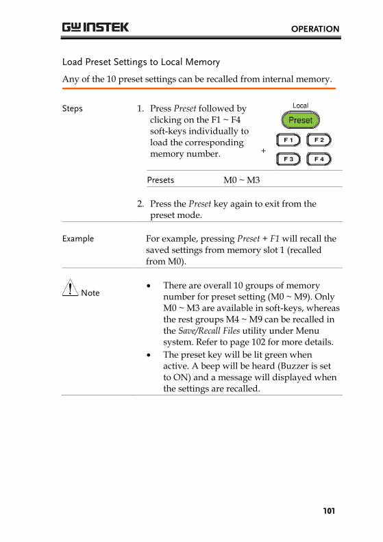
OPERATION
101
Load Preset Settings to Local Memory
Any of the 10 preset settings can be recalled from internal memory.
Steps 1. Press Preset followed by clicking on the F1 ~ F4 soft-keys individually to load the corresponding memory number.
+
Presets M0 ~ M3
2. Press the Preset key again to exit from the preset mode.
Example For example, pressing Preset + F1 will recall the saved settings from memory slot 1 (recalled from M0).
Note There are overall 10 groups of memory
number for preset setting (M0 ~ M9). Only M0 ~ M3 are available in soft-keys, whereas the rest groups M4 ~ M9 can be recalled in the Save/Recall Files utility under Menu system. Refer to page 102 for more details.
The preset key will be lit green when active. A beep will be heard (Buzzer is set to ON) and a message will displayed when the settings are recalled.
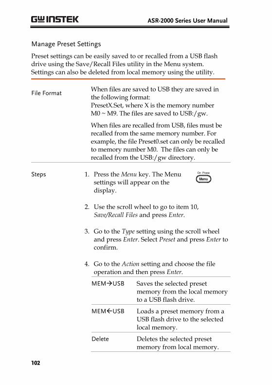
ASR-2000 Series User Manual
102
Manage Preset Settings
Preset settings can be easily saved to or recalled from a USB flash drive using the Save/Recall Files utility in the Menu system. Settings can also be deleted from local memory using the utility.
File Format When files are saved to USB they are saved in the following format: PresetX.Set, where X is the memory number M0 ~ M9. The files are saved to USB:/gw.
When files are recalled from USB, files must be recalled from the same memory number. For example, the file Preset0.set can only be recalled to memory number M0. The files can only be recalled from the USB:/gw directory.
Steps 1. Press the Menu key. The Menu settings will appear on the display.
2. Use the scroll wheel to go to item 10,Save/Recall Files and press Enter.
3. Go to the Type setting using the scroll wheeland press Enter. Select Preset and press Enter toconfirm.
4. Go to the Action setting and choose the fileoperation and then press Enter.
MEMUSB Saves the selected preset memory from the local memory to a USB flash drive.
MEMUSB Loads a preset memory from a USB flash drive to the selected local memory.
Delete Deletes the selected preset memory from local memory.
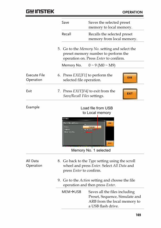
OPERATION
103
Save Saves the selected preset memory to local memory.
Recall Recalls the selected preset memory from local memory.
5. Go to the Memory No. setting and select the preset memory number to perform the operation on. Press Enter to confirm.
Memory No. 0 ~ 9 (M0 ~ M9)
Execute File Operation
6. Press EXE[F1] to perform the selected file operation.
Exit 7. Press EXIT[F4] to exit from the Save/Recall Files settings.
Example
Memory No. 1 selected
Load file from USB to Local memory
All Data Operation
8. Go back to the Type setting using the scroll wheel and press Enter. Select All Data and press Enter to confirm.
9. Go to the Action setting and choose the file operation and then press Enter.
MEMUSB Saves all the files including Preset, Sequence, Simulate and ARB from the local memory to a USB flash drive.

ASR-2000 Series User Manual
104
MEMUSB Loads all the files including Preset, Sequence, Simulate and ARB from a USB flash drive to the local memory.
Delete Deletes all the files including Preset, Sequence, Simulate and ARB from local memory.
Example
Save all data from Local memory to USB
All Data option selected
EXTERNAL CONTROL
105
EXTERNAL CONTROLThe rear panel has 3 signal output connectors. These connectors are used for external control from the menu of this product by using the external signal that includes amplified external voltage, amplified external signal as well as synchronization frequency.
Note that prior to operation, it is required to implement insulation process for external circuit. For example, while connecting to I/O signals of ASR-2000, be sure to have double insulation process for live parts in advance.
Furthermore the state output is always on. The following chapter will give a brief overview each of these connectors.
Using External Control I/O ................................... 106
Using External Signal Input Function.................... 107 EXT GAIN - AC+DC-EXT and AC-EXT mode .................. 108 EXT ADD - AC+DC-ADD and AC-ADD mode ................. 109 EXT Sync - AC+DC-Sync and AC-Sync mode ....................... 109
Compiling Arbitrary Waveform Input .................... 110

ASR-2000 Series User Manual
106
Using External Control I/O
Overview The External Control I/O is primarily used to control ASR-2000 externally by using the logic signal. More than that, it is able to monitor Sequence function status remotely with ease.
Specification Control input
High level: +2.2 V or higher
Low level: +1.0 V or lower
Non-destructive maximum input:+7 V / -5 V
Input Impedance: Pulled up to+5 V with 47 kΩ
Status output
Output level: 0 / +5 V
Output Impedance: 100 Ω
Pin Assignment Check the table below for definition of each pin.
Pin No. I/O Function Remark
1 Output Power source on/off status 0: OFF, 1: On
2 Output The output on/off status 0: OFF, 1: On
3 Output 0: OFF, 1: On
4 Output Software busy status 0: Normal, 1: Busy
5 Output Sequence sync output 0
6 Output Sequence sync output 1
7 Output Undefined output 0
8 Output Undefined output 1
9 GND
10 Input Undefined input 0
11 Input Output off Falling edge detection
12 Input Output on Falling edge detection
13 Input Sequence start Falling edge detection
14 Input Sequence stop Falling edge detection
15 Input Sequence hold Falling edge detection
16 Input Sequence branch 1 Falling edge detection
17 Input Sequence branch 2 Falling edge detection
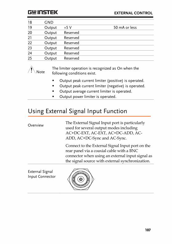
EXTERNAL CONTROL
107
18 GND
19 Output +5 V 50 mA or less
20 Output Reserved
21 Output Reserved
22 Output Reserved
23 Output Reserved
24 Output Reserved
25 Output Reserved
Note The limiter operation is recognized as On when the following conditions exist.
Output peak current limiter (positive) is operated.
Output peak current limiter (negative) is operated.
Output average current limiter is operated.
Output power limiter is operated.
Using External Signal Input Function
Overview The External Signal Input port is particularly used for several output modes including AC+DC-EXT, AC-EXT, AC+DC-ADD, AC-ADD, AC+DC-Sync and AC-Sync.
Connect to the External Signal Input port on the rear panel via a coaxial cable with a BNC connector when using an external input signal as the signal source with external synchronization.
External Signal Input Connector
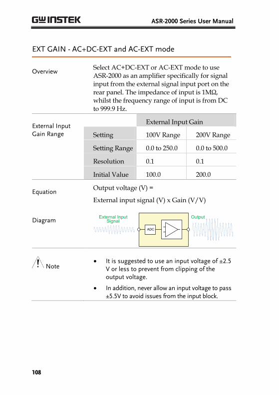
ASR-2000 Series User Manual
108
EXT GAIN - AC+DC-EXT and AC-EXT mode
Overview Select AC+DC-EXT or AC-EXT mode to use ASR-2000 as an amplifier specifically for signal input from the external signal input port on the rear panel. The impedance of input is 1MΩ, whilst the frequency range of input is from DC to 999.9 Hz.
External Input Gain Range
External Input Gain
Setting 100V Range 200V Range
Setting Range 0.0 to 250.0 0.0 to 500.0
Resolution 0.1 0.1
Initial Value 100.0 200.0
Equation Output voltage (V) =
External input signal (V) x Gain (V/V)
Diagram External Input
SignalOutput
ADC
Note It is suggested to use an input voltage of ±2.5
V or less to prevent from clipping of theoutput voltage.
In addition, never allow an input voltage to pass±5.5V to avoid issues from the input block.

EXTERNAL CONTROL
109
EXT ADD - AC+DC-ADD and AC-ADD mode
Overview & Concept
Select AC+DC-ADD or AC-ADD mode to add the external signal source signal that includes magnification to the internal signal then power output on the rear panel. The impedance of input is 1MΩ, whilst the frequency range of input is from DC to 999.9 Hz.
EXT Sync - AC+DC-Sync and AC-Sync mode
Overview When AC+DC-Sync or AC-Sync mode is selected, the externally synchronized oscillation function embedded in the ASR-2000 synchronizes the output frequency, specifically, to the frequency of external synchronization TTL signal. It is not allowed to set the synchronization phase difference and the output frequency is able to be synchronized to frequency from 40 to 999.9 Hz.
Diagram & Concept
For SIG option, choose either EXT (signal sync) or LINE (line sync) for external sync signal source. It is noted that synchronous is with power source frequency when LINE is opted. See page 74 for operation steps.
0
1
Output Waveform
External Sync Signal (TTL)

ASR-2000 Series User Manual
110
Compiling Arbitrary Waveform Input
Background In order to generate arbitrary waveforms, it is requested to use a specifically control software on external PC which transfers data, via USB interface, to the arbitrary waveform memory with ASR-2000.
Note Arbitrary waveforms cannot be changed when
output is on. To change arbitrary waveform,make sure the output is off beforehand.
It is not allowed to compile the arbitrarywaveform memory directly from ASR-2000. Only connecting with a PC with control software via USB interface can complete it.
Memory Arbitrary waveform memory count: 16
Arbitrary waveform length: 4096 words
Arbitrary waveform data: 16-bit binary (2’s complement format)
Valid range of waveform data: -32767 to 32767
When a value greater than 32767 is input, waveform data will be clipped to 32767. Also, when a value less than -32767 is input, the waveform data will be clipped to -32767.
Output Arbitrary Waveform on ASR-2000
1. Press Shift + Test to access the Wave menu. +
Alternatively, it is available to use scroll wheel followed by the Enter key to enter the Wave menu.

EXTERNAL CONTROL
111
2. Choose one of the ARB waveforms (ARB 1 toARB 16) with scroll wheel.
Default Waveform Setting
ARB 1 - 8 SIN waveform
ARB 9 - 12 SQU waveform
ARB 13 - 16 TRI waveform
3. Press Enter to confirm the waveform setting.
Example
ARB 16 selected
Note When the input peak value of ARB waveform is not in the full scale 32768, the ratio of maximum value of voltage output by ARB waveform will decrease accordingly.

ASR-2000 Series User Manual
112
Manage Arbitrary Waveform Settings
Arbitrary waveform settings can be easily saved to or from a USB flash drive using the Save/Recall Files utility in the Menu system. Files can also be deleted from local memory using the utility.
File Format When files are saved to USB they are saved in the following format: ARBX.ARB, where X is the memory number 1 ~ 16 (ARB0 ~ ARB16). The files are saved to USB:/gw.
When files are recalled from USB, files must be recalled from the same memory number. For example, the file ARB1. SEQ can only be recalled to memory number ARB1. The files can only be recalled from the USB:/gw directory.
Steps 1. Press the Menu key. The Menu settings will appear on the display.
2. Use the scroll wheel to go to item 10,Save/Recall Files and press Enter.
3. Go to the Type setting using the scroll wheeland press Enter. Select ARB and press Enter toconfirm.
4. Go to the Action setting and choose the fileoperation and then press Enter.
MEMUSB Saves the selected ARB memory from the local memory to a USB flash drive.
MEMUSB Loads the ARB memory from a USB flash drive to the selected local memory.

EXTERNAL CONTROL
113
Delete Deletes the selected ARB memory from local memory.
5. Go to the Memory No. setting and select thesequence memory number to perform theoperation on. Press Enter to confirm.
Memory No. 1 ~ 16 (ARB1 ~ ARB16)
Execute File Operation
6. Press EXE[F1] key to perform thefile operation.
Exit 7. Press EXIT[F4] key to exit fromthe Save/Recall Files settings.
Example
Memory No. 1 selected
Load file from USB to Local memory
All Data Operation
8. Go back to the Type setting using the scrollwheel and press Enter. Select All Data andpress Enter to confirm.
9. Go to the Action setting and choose the fileoperation and then press Enter.
MEMUSB Saves all the files including Preset, Sequence, Simulate and ARB from the local memory to a USB flash drive.
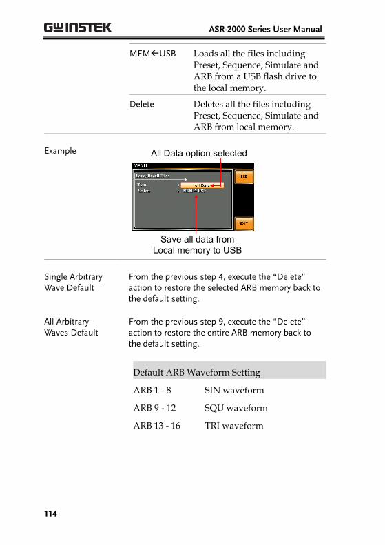
ASR-2000 Series User Manual
114
MEMUSB Loads all the files including Preset, Sequence, Simulate and ARB from a USB flash drive to the local memory.
Delete Deletes all the files including Preset, Sequence, Simulate and ARB from local memory.
Example
Save all data from Local memory to USB
All Data option selected
Single Arbitrary Wave Default
From the previous step 4, execute the “Delete” action to restore the selected ARB memory back to the default setting.
All Arbitrary Waves Default
From the previous step 9, execute the “Delete” action to restore the entire ARB memory back to the default setting.
Default ARB Waveform Setting
ARB 1 - 8 SIN waveform
ARB 9 - 12 SQU waveform
ARB 13 - 16 TRI waveform

MISCELLANEOUS
115
MISCELLANEOUSThe Miscellaneous menu contains miscellaneous parameter settings.
T Ipeak, hold ......................................................... 116
Ipkh CLR ................................................................ 118
Power ON .............................................................. 119
Buzzer ................................................................... 120
Remote Sense ........................................................ 121
Slew Rate Mode ..................................................... 123
Output Relay ......................................................... 124
THD Format .......................................................... 125
External Control I/O .............................................. 127

ASR-2000 Series User Manual
116
T Ipeak, hold The T Ipeak, hold function sets the hold time for the peak current measurement. After the output is turned on, the ASR-2000 will delay starting the peak current measurement by this hold time.
Concept in diagram
Output on
Ipeak Hold time
I
Hold the peak current measurement value
T
Note The hold peak current will be updated when new
measurement is greater than the previous value. By contrast, it will not update when new measurement is less than the hold peak current.
Ipeak hold time begins counting only when the output function is turned on.
Ipeak measurement is not executed during the set Ipeak hold time.
Steps 1. Press the Menu key. The Menu setting will appear on the display.
2. Use the scroll wheel to go to item 2, MISC Configuration and press Enter.
3. Go to the T Ipeak, hold(msec) setting using thescroll wheel and press Enter. Set the time andpress Enter again to confirm.
T Ipeak 1 ~ 60,000 ms

MISCELLANEOUS
117
Exit 4. Press Exit[F4] to exit from theMISC Configuration settings.
Example
Hold time of current peak value setting
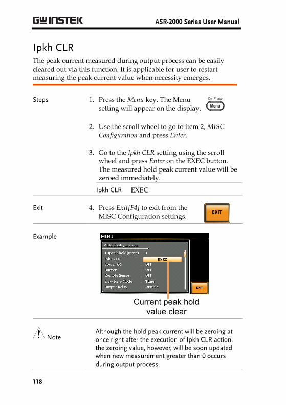
ASR-2000 Series User Manual
118
Ipkh CLR The peak current measured during output process can be easily cleared out via this function. It is applicable for user to restart measuring the peak current value when necessity emerges.
Steps 1. Press the Menu key. The Menu setting will appear on the display.
2. Use the scroll wheel to go to item 2, MISC Configuration and press Enter.
3. Go to the Ipkh CLR setting using the scroll wheel and press Enter on the EXEC button. The measured hold peak current value will be zeroed immediately.
Ipkh CLR EXEC
Exit 4. Press Exit[F4] to exit from the MISC Configuration settings.
Example
Current peak hold value clear
Note Although the hold peak current will be zeroing at once right after the execution of Ipkh CLR action, the zeroing value, however, will be soon updated when new measurement greater than 0 occurs during output process.
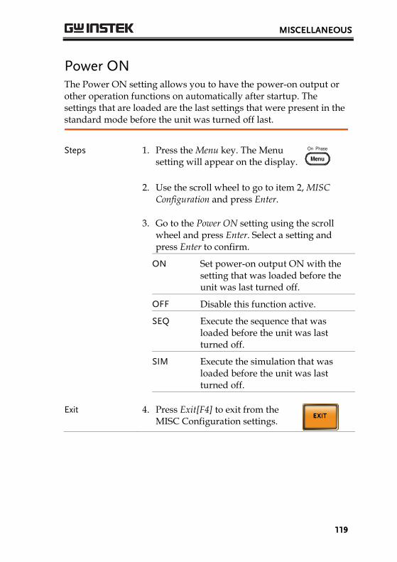
MISCELLANEOUS
119
Power ON The Power ON setting allows you to have the power-on output or other operation functions on automatically after startup. The settings that are loaded are the last settings that were present in the standard mode before the unit was turned off last.
Steps 1. Press the Menu key. The Menu setting will appear on the display.
2. Use the scroll wheel to go to item 2, MISC Configuration and press Enter.
3. Go to the Power ON setting using the scrollwheel and press Enter. Select a setting andpress Enter to confirm.
ON Set power-on output ON with the setting that was loaded before the unit was last turned off.
OFF Disable this function active.
SEQ Execute the sequence that was loaded before the unit was last turned off.
SIM Execute the simulation that was loaded before the unit was last turned off.
Exit 4. Press Exit[F4] to exit from theMISC Configuration settings.

ASR-2000 Series User Manual
120
Example
Power ON setting
Buzzer The Buzzer setting turns the buzzer sound on or off for key presses.
Steps 1. Press the Menu key. The Menu setting will appear on the display.
2. Use the scroll wheel to go to item 2, MISC Configuration and press Enter.
3. Go to the Buzzer setting using the scroll wheeland press Enter. Turn the setting on or off andpress Enter again to confirm.
Buzzer ON, OFF
Exit 4. Press Exit[F4] to exit from theMISC Configuration settings.
Example
Buzzer setting
Note When any alarm occurs, buzzer always beeps regardless of the setting in on or off.

MISCELLANEOUS
121
Remote Sense The remote sense function detects the output voltage at the sensing input terminal. This function compensates for voltage drops across the load cables when the load is connected to the ASR-2000 over a long distance.
Note The remote sense function can compensate a maximum of 5% of the output voltage. The maximum output voltage when compensation is used is limited by the rated voltage.
Steps 1. Press the Menu key. The Menu setting will appear on the display.
2. Use the scroll wheel to go to item 2, MISC Configuration and press Enter.
3. Go to the Remote Sense setting using the scrollwheel and press Enter. Turn the setting on oroff and press Enter again to confirm.
Remote Sense ON, OFF
Exit 4. Press Exit[F4] to exit from theMISC Configuration settings.
Example
Remote Sense setting
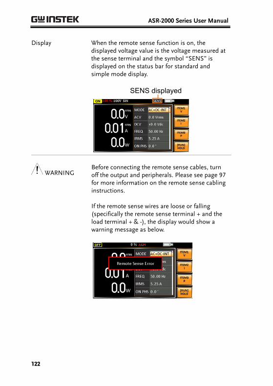
ASR-2000 Series User Manual
122
Display When the remote sense function is on, the displayed voltage value is the voltage measured at the sense terminal and the symbol “SENS” is displayed on the status bar for standard and simple mode display.
SENS displayed
WARNING Before connecting the remote sense cables, turn off the output and peripherals. Please see page 97 for more information on the remote sense cabling instructions.
If the remote sense wires are loose or falling (specifically the remote sense terminal + and the load terminal + & -), the display would show a warning message as below.
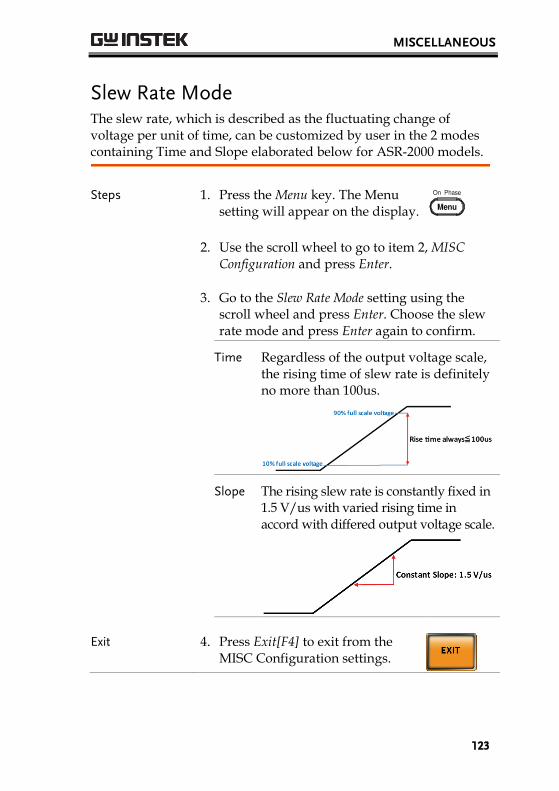
MISCELLANEOUS
123
Slew Rate Mode The slew rate, which is described as the fluctuating change of voltage per unit of time, can be customized by user in the 2 modes containing Time and Slope elaborated below for ASR-2000 models.
Steps 1. Press the Menu key. The Menu setting will appear on the display.
2. Use the scroll wheel to go to item 2, MISC Configuration and press Enter.
3. Go to the Slew Rate Mode setting using the scroll wheel and press Enter. Choose the slew rate mode and press Enter again to confirm.
Time Regardless of the output voltage scale, the rising time of slew rate is definitely no more than 100us.
Slope The rising slew rate is constantly fixed in 1.5 V/us with varied rising time in accord with differed output voltage scale.
Exit 4. Press Exit[F4] to exit from the MISC Configuration settings.

ASR-2000 Series User Manual
124
Voltage drop occurs in output voltage due to the set waveform or frequency under the Slope mode. It is suggested to adopt the Time mode when precise sine wave voltage output is required.
Example
Slew Rate setting
Output Relay The internally built-in output relay function has close relation with the power output function by default. That is to say, when output is on, the output relay will be activated if output relay is enabled; by contrast, the output relay will be deactivated when output is off. On the other hand, output relay function disabled means output terminal is under the condition of high impedance and output relay retains the state of conducting for good, which is suitable for the condition of turning output on/off rapidly.
Steps 1. Press the Menu key. The Menu setting will appear on the display.
2. Use the scroll wheel to go to item 2, MISC Configuration and press Enter.
3. Go to the Output Relay setting using the scrollwheel and press Enter. Enable or disable outputrelay mode and press Enter again to confirm.
Output Relay Enable, Disable
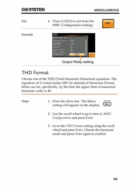
MISCELLANEOUS
125
Exit 4. Press Exit[F4] to exit from theMISC Configuration settings.
Example
Output Relay setting
THD Format Choose one of the THD (Total Harmonic Distortion) equations. The equations of 2 varied modes (IEC by default) of Harmonic Format below are for, specifically, by the time the upper limit of measured harmonic order is 40.
Steps 1. Press the Menu key. The Menu setting will appear on the display.
2. Use the scroll wheel to go to item 2, MISC Configuration and press Enter.
3. Go to the THD Format setting using the scrollwheel and press Enter. Choose the harmonicmode and press Enter again to confirm.

ASR-2000 Series User Manual
126
IEC & Equation
The ratio of rms value of the second to the 40th harmonic component is computed to that of the fundamental.
CSA & Equation
The ratio of rms value of the second to the 40th harmonic component is computed to that of the rms value of the first to 40th component.
Parameter F1: Fundamental (1st harmonic)component
FO: Fundamental or harmoniccomponent
O: Measured harmonic order
N: Upper limit of measuredharmonic order, which varies inaccord with the fundamentalfrequency.
Exit 4. Press Exit[F4] to exit from theMISC Configuration settings.

MISCELLANEOUS
127
Example
THD Format setting
External Control I/O User can enable or disable the External Control I/O input. When External Control I/O input is set as disabled, the ASR-2000 series status will remain output.
Steps 1. Press the Menu key. The Menu setting will appear on the display.
2. Use the scroll wheel to go to item 2, MISC Configuration and press Enter.
3. Go to the External Control setting using thescroll wheel and press Enter. Enable or disableExternal Control I/O and press Enter again toconfirm selection.
ON Signal will be input from the pin 11 to the pin 17 of External Control I/O, and ASR-2000 series is able to receive external input signal and execute control action.
OFF Signal will be input from the pin 11 to the pin 17 of External Control I/O, and ASR-2000 series is Not able to receive external input signal.
ASR-2000 Series User Manual
128
TEST MODE FUNCTIONThere are two test modes, Sequence Mode and Simulate Mode respectively, available for user to execute. Refer to the following chapters for details in necessity.
Sequence Mode ..................................................... 129 Sequence Mode Overview ............................................................ 129 Sequence Settings ........................................................................... 134 Save a Sequence to Local Memory ............................................. 139 Recall a Sequence from Local Memory ...................................... 139 Manage Sequence Settings ............................................................ 140 Running a Sequence ....................................................................... 143
Simulate Mode ...................................................... 145 Simulate Mode Overview ............................................................. 145 Simulate Settings ............................................................................ 149 Save a Simulation to Local Memory ........................................... 153 Recall a Simulation from Local Memory ................................... 153 Manage Simulation Settings ......................................................... 154 Running a Simulation .................................................................... 157

TEST MODE FUNCTION
129
Sequence Mode
Sequence Mode Overview
Background The Sequence function works with DC-INT, AC-INT and AC+DC-INT modes with full AC waveforms containing sine, square, triangle as well as arbitrary. The available parameters, which will be introduced in later sectors, vary depending on selected output modes.
A Sequence function is comprised of up to the maximum 999 steps.
Setting Screen Overview
Test ModeV RANGE
Recall TestSave Test
Run Test
Branch 2Sync Code
Branch 1Step TerminationOn Phase Off Phase
DC VoltageAC VoltageStep Number
Step TimeFrequencyWaveform
Jump To
Jump Count
Sequence Parameter Overview
The Sequence function is comprised of a minimum of 2 steps that are executed in user defined sequences.
Each step can have different step time, voltage level, start & stop phase, frequency and wave.
Note: Step 0 is assigned as a “Standby” step. At the end of the test the unit will shift to the standby step.
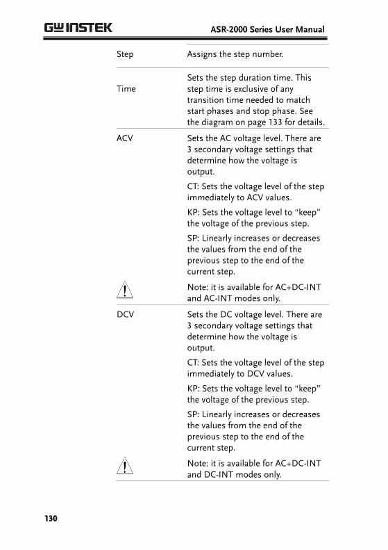
ASR-2000 Series User Manual
130
Step Assigns the step number.
Time Sets the step duration time. This step time is exclusive of any transition time needed to match start phases and stop phase. See the diagram on page 133 for details.
ACV Sets the AC voltage level. There are 3 secondary voltage settings that determine how the voltage is output.
CT: Sets the voltage level of the step immediately to ACV values.
KP: Sets the voltage level to “keep” the voltage of the previous step.
SP: Linearly increases or decreases the values from the end of the previous step to the end of the current step.
Note: it is available for AC+DC-INT and AC-INT modes only.
DCV Sets the DC voltage level. There are 3 secondary voltage settings that determine how the voltage is output.
CT: Sets the voltage level of the step immediately to DCV values.
KP: Sets the voltage level to “keep” the voltage of the previous step.
SP: Linearly increases or decreases the values from the end of the previous step to the end of the current step.
Note: it is available for AC+DC-INT and DC-INT modes only.

TEST MODE FUNCTION
131
AC/DC Voltage Range (ACV/DCV)
There are 2 voltage range settings: HI 200V & LO 100V, which result in varied ranges of ACV and DCV values, respectively.
Fset (Frequency) Sets the frequency of the step.
There are 3 secondary frequency settings that determine how the frequency is output.
CT: Sets the frequency level of the step immediately to Fset values.
KP: Sets the frequency level to “keep” the frequency of the previous step.
SP: Linearly increases or decreases the frequency from the end of the previous step to the end of the current step.
Note: it is available for AC+DC-INT and AC-INT modes only.
Wave Sets the outputting waveform of the
step. Up to 4 waves including sine, square, triangle and arbitrary (1-16) wave shapes are available.
Note: it is available for AC+DC-INT and AC-INT modes only.
Jump To The Jump To setting determines
which step to jump to at the end of the step. If Jump To is turned off, the unit will follow the Term (Step termination) setting for the step.
Jump Cnt Determines the number of times to
loop the jump step.

ASR-2000 Series User Manual
132
Branch1/ Branch2
The Branch settings allow you to make a selectable branch within the sequence when the sequence is running or on hold. The branch1 or branch2 actions are enabled by pressing the F1 or F2 function keys, or by using the :TRIG:SEQ:SEL:EXEC remote control command. After the branch step(s) have completed the unit will return back to the step from which the branch was executed and continue to run the step from where it left off.
Term (Termination)
Determines the step termination settings at end of the step.
The CONTI setting tells the sequence to go to the next step.
The HOLD setting will pause the output at the end of the step and will only continue to the next step when CONTI [F3] is pressed.
The END setting will end the sequence and go to Step 0(standby step).
Sync Code Sets the synchronous code including LL, LH, HL and HH for each step.
ON/OFF Phs Sets the start and stop phase of the AC waveform for each step. The ON Phs setting sets the starting phase of the step.
OFF Phs sets the off phase for the output when the output if turned off.
Note: it is available for AC+DC-INT and AC-INT modes only.
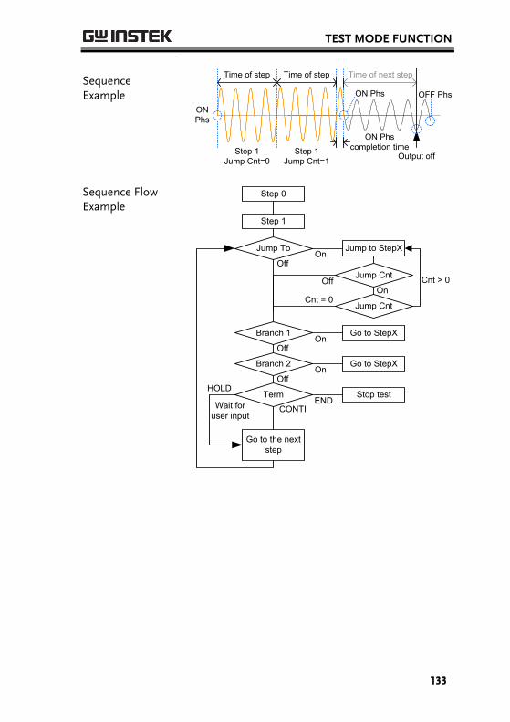
TEST MODE FUNCTION
133
Sequence Example
Time of step Time of next step
ON Phs completion time
ON Phs
ON Phs
Step 1 Jump Cnt=0
Step 1 Jump Cnt=1
Time of step
Output off
OFF Phs
Sequence Flow Example
Step 1
Jump To
Branch 1
Go to StepX
Go to StepX
Cnt > 0
Branch 2
Jump to StepX
OnOff
OnOff
OnOff
Jump Cnt
OnOff
Go to the next step
TermEND
CONTI
HOLDStop test
Wait for user input
Jump CntCnt = 0
Step 0
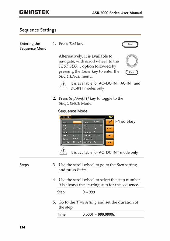
ASR-2000 Series User Manual
134
Sequence Settings
Entering the Sequence Menu
1. Press Test key. Test
Alternatively, it is available to navigate, with scroll wheel, to the TEST SEQ… option followed by pressing the Enter key to enter the SEQUENCE menu.
It is available for AC+DC-INT, AC-INT and DC-INT modes only.
2. Press Seq/Sim[F1] key to toggle to theSEQUENCE Mode.
Sequence Mode
F1 soft-key
It is available for AC+DC-INT mode only.
Steps 3. Use the scroll wheel to go to the Step settingand press Enter.
4. Use the scroll wheel to select the step number.0 is always the starting step for the sequence.
Step 0 ~ 999
5. Go to the Time setting and set the duration ofthe step.
Time 0.0001 ~ 999.9999s

TEST MODE FUNCTION
135
6. In order to adjust both ACV and DCV voltage range between HI and LO, it is required to set up outside of the SEQUENCE menu. Refer to the page 62 for details. The selected range will be shown on the top bar.
Range
Range LO - 100V, HI - 200V
7. Go to the ACV setting and set the output voltage for the step. If you input an ACV value that is not within the voltage range, the warning message below will be shown.
Next set the secondary voltage settings to determine characteristics of the voltage output.
ACV 0.0 ~ 350.0V (Range 200V) 0.0 ~ 175.0V (Range 100V)
Secondary settings
CT (Constant), KP (Keep), SP (Sweep)
Note: Step 0 can only be set to either CT or SP.
8. Go to the DCV setting and set the output voltage for the step. If you input a DCV value that is not within the voltage range, the warning message below will be shown.
Next set the secondary voltage settings to determine characteristics of the voltage output.
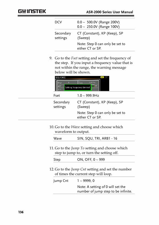
ASR-2000 Series User Manual
136
DCV 0.0 ~ 500.0V (Range 200V) 0.0 ~ 250.0V (Range 100V)
Secondary settings
CT (Constant), KP (Keep), SP (Sweep)
Note: Step 0 can only be set to either CT or SP.
9. Go to the Fset setting and set the frequency ofthe step. If you input a frequency value that isnot within the range, the warning messagebelow will be shown.
Fset 1.0 ~ 999.9Hz
Secondary settings
CT (Constant), KP (Keep), SP (Sweep)
Note: Step 0 can only be set to either CT or SP.
10. Go to the Wave setting and choose whichwaveform to output.
Wave SIN, SQU, TRI, ARB1 - 16
11. Go to the Jump To setting and choose whichstep to jump to, or turn the setting off.
Step ON, OFF, 0 ~ 999
12. Go to the Jump Cnt setting and set the numberof times the current step will loop.
Jump Cnt 1 ~ 9999, 0
Note: A setting of 0 will set the number of jump step to be infinite.

TEST MODE FUNCTION
137
13. Go to the Branch 1/2 setting and set a step to branch to.
Branch 1, 2 ON, OFF, 0 ~ 999
14. Go to the Term setting and set the step termination setting. CONTI will automatically go to the next step at the end of the step. END will return to step 0. HOLD will stay at the current step until you allow the sequence to continue to the next step.
Term CONTI, END, HOLD
15. Go to the Sync Code setting and set the synchronous code when the step has started.
Sync Code LL, LH, HL, HH
16. Go to the ON Phs setting and set the starting phase of the step. The Fixed indicates user-defined degree.
ON Phase Free, Fixed
ON Phase 0.0 ~ 359.9º
Resolution 0.1º
17. Go to the OFF Phs setting and set the end phase of the step. The Fixed indicates user-defined degree.
OFF Phase Free, Fixed
OFF Phase 0.0 ~ 359.9º
Resolution 0.1º
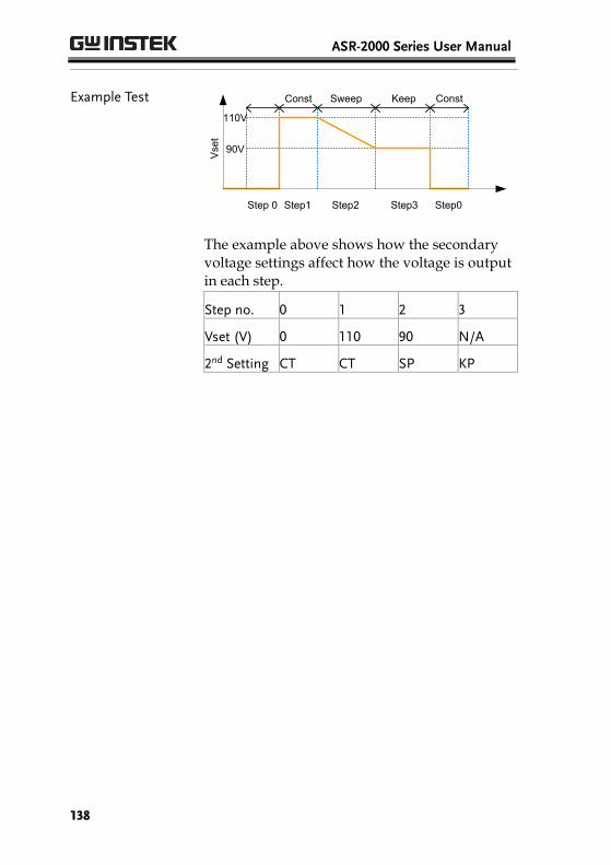
ASR-2000 Series User Manual
138
Example Test
Step 0 Step3Step1 Step2 Step0
Sweep Keep Const
Vset
110V
90V
Const
The example above shows how the secondary voltage settings affect how the voltage is output in each step.
Step no. 0 1 2 3
Vset (V) 0 110 90 N/A
2nd Setting CT CT SP KP
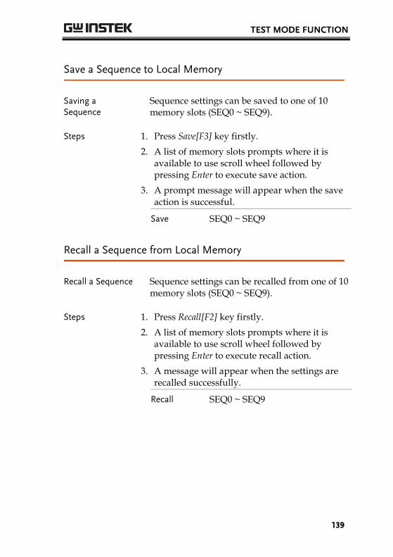
TEST MODE FUNCTION
139
Save a Sequence to Local Memory
Saving a Sequence
Sequence settings can be saved to one of 10 memory slots (SEQ0 ~ SEQ9).
Steps 1. Press Save[F3] key firstly.
2. A list of memory slots prompts where it is available to use scroll wheel followed by pressing Enter to execute save action.
3. A prompt message will appear when the save action is successful.
Save SEQ0 ~ SEQ9
Recall a Sequence from Local Memory
Recall a Sequence Sequence settings can be recalled from one of 10 memory slots (SEQ0 ~ SEQ9).
Steps 1. Press Recall[F2] key firstly.
2. A list of memory slots prompts where it is available to use scroll wheel followed by pressing Enter to execute recall action.
3. A message will appear when the settings are recalled successfully.
Recall SEQ0 ~ SEQ9

ASR-2000 Series User Manual
140
Manage Sequence Settings
Sequence settings can be easily saved to or from a USB flash drive using the Save/Recall Files utility in the Menu system. Files can also be deleted from local memory using the utility.
File Format When files are saved to USB they are saved in the following format: SEQX.SEQ, where X is the memory number 0 ~ 9 (SEQ0 ~ SEQ9). The files are saved to USB:/gw.
When files are recalled from USB, files must be recalled from the same memory number. For example, the file SEQ0. SEQ can only be recalled to memory number SEQ0. The files can only be recalled from the USB:/gw directory.
Steps 4. Press the Menu key. The Menu settings will appear on the display.
5. Use the scroll wheel to go to item 10,Save/Recall Files and press Enter.
6. Go to the Type setting using the scroll wheeland press Enter. Select SEQUENCE and pressEnter to confirm.
7. Go to the Action setting and choose the fileoperation and then press Enter.
MEMUSB Saves the selected sequence memory from the local memory to a USB flash drive.
MEMUSB Loads the sequence memory from a USB flash drive to the selected local memory.

TEST MODE FUNCTION
141
Delete Deletes the selected sequence memory from local memory.
8. Go to the Memory No. setting and select thesequence memory number to perform theoperation on. Press Enter to confirm.
Memory No. 0 ~ 9 (SEQ0 ~ SEQ9)
Execute File Operation
9. Press EXE[F1] key to perform thefile operation.
Exit 10. Press EXIT[F4] key to exit fromthe Save/Recall Files settings.
Example
Memory No. 0 selected
Load file from USB to Local memory
All Data Operation
11. Go back to the Type setting using the scrollwheel and press Enter. Select All Data andpress Enter to confirm.
12. Go to the Action setting and choose the fileoperation and then press Enter.
MEMUSB Saves all the files including Preset, Sequence, Simulate and ARB from the local memory to a USB flash drive.

ASR-2000 Series User Manual
142
MEMUSB Loads all the files including Preset, Sequence, Simulate and ARB from a USB flash drive to the local memory.
Delete Deletes all the files including Preset, Sequence, Simulate and ARB from local memory.
Example
Save all data from Local memory to USB
All Data option selected
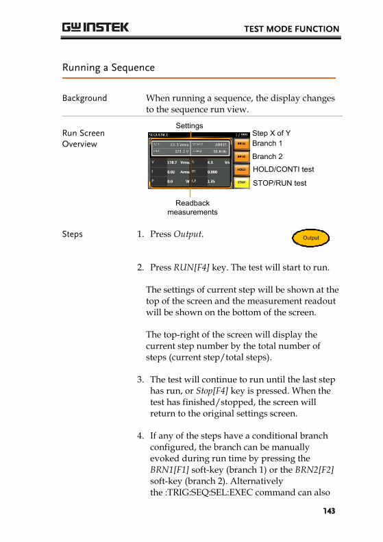
TEST MODE FUNCTION
143
Running a Sequence
Background When running a sequence, the display changes to the sequence run view.
Run Screen Overview
SettingsStep X of Y
Branch 2
HOLD/CONTI test
STOP/RUN test
Readback measurements
Branch 1
Steps 1. Press Output.Output
2. Press RUN[F4] key. The test will start to run.
The settings of current step will be shown at thetop of the screen and the measurement readoutwill be shown on the bottom of the screen.
The top-right of the screen will display thecurrent step number by the total number ofsteps (current step/total steps).
3. The test will continue to run until the last stephas run, or Stop[F4] key is pressed. When thetest has finished/stopped, the screen willreturn to the original settings screen.
4. If any of the steps have a conditional branchconfigured, the branch can be manuallyevoked during run time by pressing theBRN1[F1] soft-key (branch 1) or the BRN2[F2]soft-key (branch 2). Alternativelythe :TRIG:SEQ:SEL:EXEC command can also
ASR-2000 Series User Manual
144
be used evoke a conditional branch.
Hold Test 5. To pause the test mid-way, press HOLD[F3] key.
Continue Test 6. To continued a paused test, press CONTI[F3] key.

TEST MODE FUNCTION
145
Simulate Mode
Simulate Mode Overview
Background The Simulate function, which works in AC+DC-INT mode only, is used to test power supply fluctuation. This function is able to simulate common abnormalities in mains power such as fluctuations in voltage, phase and frequency. These simulations can be run as one-off anomalies or cyclic anomalies.
Setting Screen Overview
Number of Repeat
Sync Code
Step WaveStep FrequencyStep VoltageStep
ON/OFF PhaseStep Time
Test ModeV RANGE
Recall Test
Save Test
Run Test
Step Overview The Simulate function is comprised of 6 steps. Each step is run sequentially in the following order: Initial, Normal1, Trans1, Abnormal, Trans2, Normal2 and Initial.
Initial
The Initial step is used as the initial and final settings of the waveform simulation. This is the standby step before the test starts and the standby step after the test ends.
Normal1 This step configures the normal output conditions that precede the abnormal conditions.
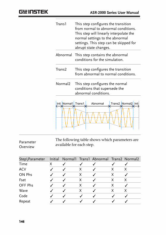
ASR-2000 Series User Manual
146
Trans1 This step configures the transition from normal to abnormal conditions. This step will linearly interpolate the normal settings to the abnormal settings. This step can be skipped for abrupt state changes.
Abnormal
This step contains the abnormal conditions for the simulation.
Trans2
This step configures the transition from abnormal to normal conditions.
Normal2 This step configures the normal conditions that supersede the abnormal conditions.
AbnormalTrans1Normal1Init Trans2 Normal2 Init
Parameter Overview
The following table shows which parameters are available for each step.
Step\Parameter Initial Normal1 Trans1 Abnormal Trans2 Normal2
Time X ✓ ✓ ✓ ✓ ✓
ACV ✓ ✓ X ✓ X X
ON Phs ✓ ✓ X ✓ X ✓
Fset ✓ ✓ X ✓ X X
OFF Phs ✓ ✓ X ✓ X ✓
Wave ✓ ✓ X ✓ X X
Code ✓ ✓ ✓ ✓ ✓ ✓
Repeat ✓ ✓ ✓ ✓ ✓ ✓

TEST MODE FUNCTION
147
Time Sets the duration time of the step. When the ON Phs=ON, the total duration of the step is equal to the Time setting + ON Phs=ON duration.
ACV Sets the voltage of the step. Not applicable for the Trans 1/2 steps and the Normal2 step.
ON Phs Sets the starting phase of the waveform for the step. Not applicable for the Trans 1/2 steps.
Fset Sets the frequency of the step. Not applicable for the Trans 1/2 steps and the Normal2 step.
OFF Phs Sets the off phase of the waveform after the output has been turned off. Not applicable for the Trans 1/2 steps.
Wave Sets the outputting waveform of the step. Not applicable for the Trans 1/2 steps and the Normal2 step.
Code Sets the synchronous code including LL, LH, HL and HH for the duration of the step.
Repeat Indicates the number of times the simulation will be run, from Normal1 to Normal2.
A value of 0 indicates infinite repeats. The repeat setting is the same for each step.

ASR-2000 Series User Manual
148
The following diagram illustrates the relationship between each of the parameters in a step.
Time
ON Phs
ON Phs additional time
Output off
OFF Phs
Trigger out position
Fset
OFF Phs additional time
Vset

TEST MODE FUNCTION
149
Simulate Settings
Entering the Simulate Menu
1. Press Test key. Test
Alternatively, it is available to navigate, with scroll wheel, to the TEST SIM… option followed by pressing the Enter key to enter the SIMULATE menu.
It is available for AC+DC-INT mode only.
2. Press Seq/Sim[F1] key to toggle to the SIMULATE Mode.
Simulate Mode
F1 soft-key
Steps 3. Use the scroll wheel to go to the Step setting and press Enter.
4. Use the scroll wheel to select one of the simulate steps and press Enter.
Steps Initial, Normal1, Trans1, Abnormal, Trans2, Normal2
5. Go to the Time setting and set the duration of the step.

ASR-2000 Series User Manual
150
Time 0.0001 ~ 999.9999s (Normal1, Normal2 and Abnormal)
0.0000 ~ 999.9999s (Trans1 and Trans2)
Note: For Trans1 and Trans2, it supports a value of 0, which will skip the step.
6. In order to adjust ACV voltage range between HI and LO, it is required to set up outside of the SIMULATE menu. Refer to the page 62 for details. The selected range will be shown on the top bar.
Range
Range LO - 100V, HI - 200V
7. Go to the ACV setting and set the Vrms level of the step. If you input an ACV value that is not within the voltage range, the warning message below will be shown. Not applicable for Trans1, Trans2 and Normal2.
ACV 0.0 ~ 350.0V (Range 200V)
0.0 ~ 175.0V (Range 100V)

TEST MODE FUNCTION
151
8. Go to the ON Phs setting and set the startingphase of the step.
Not applicable for Trans1 and Trans2.
ON Phase Free, Fixed
ON Phase 0.0 ~ 359.9º
Resolution 0.1º
9. Go to the Fset setting set the frequency of step.If you input a frequency value that is notwithin the range, the warning message belowwill be shown.
Not applicable for Trans1, Trans2 and Normal2.
Fset 1.0 ~ 999.9Hz
10. Go to the OFF Phs setting and set the endphase of the step.
Not applicable for Trans1 and Trans2.
OFF Phase Free, Fixed
OFF Phase 0.0 ~ 359.9º
Resolution 0.1º
11. Go to the Wave setting and set the wave of step.
Not applicable for Trans1, Trans2 and Normal2.
Wave SINE
12. Go to the Code setting and set the synchronouscode of the step.
Code LL, LH, HL, HH

ASR-2000 Series User Manual
152
13. Lastly, go to the Repeat parameter select the number of times the simulation will repeat the Normal1-Trans1-Abnormal-Trans2-Normal2 sequence of steps. A value of 0 will set the number of repetitions to infinite.
Repeat 1 ~ 9999, 0(infinite)

TEST MODE FUNCTION
153
Save a Simulation to Local Memory
Saving a Simulation
Simulation settings can be saved to one of 10 memory slots (SIM0 ~ SIM9).
Steps 1. Press Save[F3] key firstly.
2. A list of memory slots prompts where it is available to use scroll wheel followed by pressing Enter to execute save action.
3. A prompt message will appear when the save action is successful.
Save SIM0 ~ SIM9
Recall a Simulation from Local Memory
Recall a Simulation
Simulation settings can be recalled from one of 10 memory slots (SIM0 ~ SIM9).
Steps 1. Press Recall[F2] key firstly.
2. A list of memory slots prompts where it is available to use scroll wheel followed by pressing Enter to execute recall action.
3. A message will appear when the settings are recalled successfully.
Recall SIM0 ~ SIM9
ASR-2000 Series User Manual
154
Manage Simulation Settings
Simulation settings can be easily saved to or from a USB flash drive using the Save/Recall Files utility in the Menu system. Files can also be deleted from local memory using the utility.
File Format When files are saved to USB they are saved in the following format: SIMX. SIM, where X is the memory number 0 ~ 9 (SIM0 ~ SIM9). The files are saved to USB:/gw.
When files are recalled from USB, files must be recalled from the same memory number. For example, the file sim0.sim can only be recalled to memory number SIM0. The files can only be recalled from the USB:/gw directory.
Steps 1. Press the Menu key. The Menu settings will appear on the display.
2. Use the scroll wheel to go to item 10,Save/Recall Files and press Enter.
3. Go to the Type setting using the scroll wheeland press Enter. Select SIMULATE and pressEnter to confirm.
4. Go to the Action setting and choose the fileoperation and then press Enter.
MEMUSB Saves the selected simulation memory from the local memory to a USB flash drive.
MEMUSB Loads the simulation memory from a USB flash drive to the selected local memory.
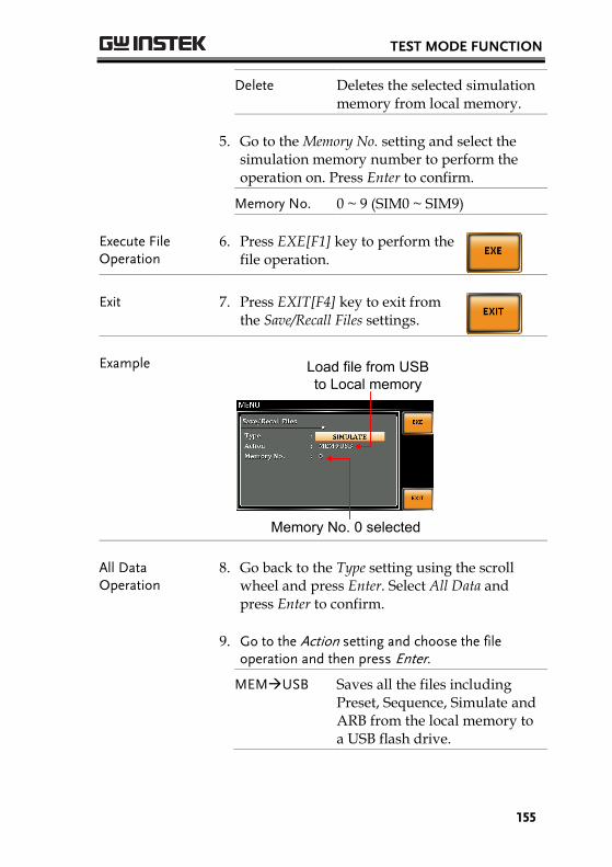
TEST MODE FUNCTION
155
Delete Deletes the selected simulation memory from local memory.
5. Go to the Memory No. setting and select thesimulation memory number to perform theoperation on. Press Enter to confirm.
Memory No. 0 ~ 9 (SIM0 ~ SIM9)
Execute File Operation
6. Press EXE[F1] key to perform thefile operation.
Exit 7. Press EXIT[F4] key to exit fromthe Save/Recall Files settings.
Example
Memory No. 0 selected
Load file from USB to Local memory
All Data Operation
8. Go back to the Type setting using the scrollwheel and press Enter. Select All Data andpress Enter to confirm.
9. Go to the Action setting and choose the fileoperation and then press Enter.
MEMUSB Saves all the files including Preset, Sequence, Simulate and ARB from the local memory to a USB flash drive.
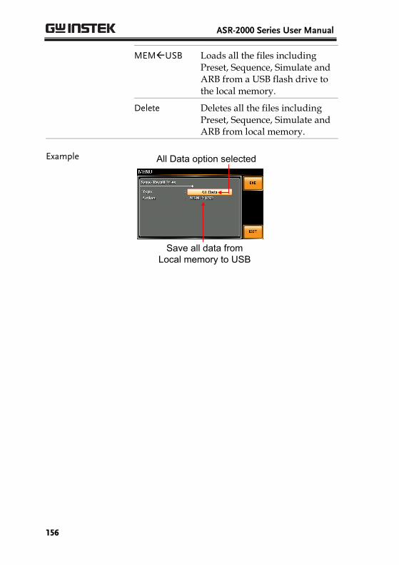
ASR-2000 Series User Manual
156
MEMUSB Loads all the files including Preset, Sequence, Simulate and ARB from a USB flash drive to the local memory.
Delete Deletes all the files including Preset, Sequence, Simulate and ARB from local memory.
Example
Save all data from Local memory to USB
All Data option selected
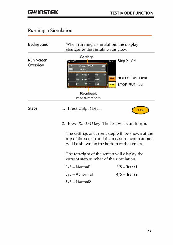
TEST MODE FUNCTION
157
Running a Simulation
Background When running a simulation, the display changes to the simulate run view.
Run Screen Overview
SettingsStep X of Y
HOLD/CONTI test
STOP/RUN test
Readback measurements
Steps 1. Press Output key.Output
2. Press Run[F4] key. The test will start to run.
The settings of current step will be shown at thetop of the screen and the measurement readoutwill be shown on the bottom of the screen.
The top-right of the screen will display thecurrent step number of the simulation.
1/5 = Normal1 2/5 = Trans1
3/5 = Abnormal 4/5 = Trans2
5/5 = Normal2
ASR-2000 Series User Manual
158
3. The test will continue to run until the lastrepeat step has run, or Stop[F4] key is pressedor the output is turned off*. When the test hasfinished/stopped, the screen will return to theoriginal settings screen.
* If the OFF-phase has been set, the output willcontinue until the OFF-phase setting issatisfied.
Hold Test 4. To pause the test mid-way, press HOLD[F3] key.
Continue Test 5. To continued a paused test, press CONTI[F3] key.
COMMUNICATION INTERFACE
159
COMMUNICATION
INTERFACE
Note
If the instrument is remotely controlled via the USB/LAN/RS-232/GPIB interface, the panel lock is automatically enabled.
Interface Configuration ......................................... 160 Configure Ethernet Connection.................................................. 160 USB Remote Interface .................................................................. 161 USB Remote Control Function Check ...................................... 163 RS-232 Remote Interface (Optional 1) ...................................... 164 RS232 Remote Control Function Check ................................... 166 Using Realterm to Establish a Remote Connection ................ 167 GPIB Remote Interface (Optional 1) ........................................ 170 GPIB Function Check .................................................................. 171 Web Server Remote Control Function Check .......................... 174 Socket Server Function Check .................................................... 175
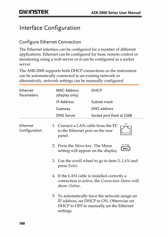
ASR-2000 Series User Manual
160
Interface Configuration
Configure Ethernet Connection
The Ethernet interface can be configured for a number of different applications. Ethernet can be configured for basic remote control or monitoring using a web server or it can be configured as a socket server.
The ASR-2000 supports both DHCP connections so the instrument can be automatically connected to an existing network or alternatively, network settings can be manually configured.
Ethernet Parameters
MAC Address (display only)
DHCP
IP Address Subnet mask
Gateway DNS address
DNS Server Socket port fixed at 2268
Ethernet Configuration
1. Connect a LAN cable from the PC to the Ethernet port on the rear panel.
LA
2. Press the Menu key. The Menu
setting will appear on the display.
3. Use the scroll wheel to go to item 3, LAN and press Enter.
4. If the LAN cable is installed correctly a connection is active, the Connection Status will show Online.
5. To automatically have the network assign an IP address, set DHCP to ON. Otherwise set DHCP to OFF to manually set the Ethernet settings.
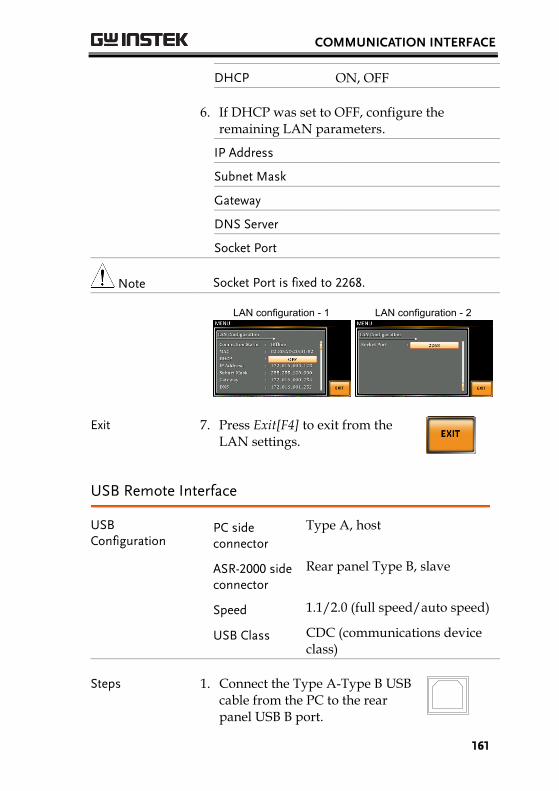
COMMUNICATION INTERFACE
161
DHCP ON, OFF
6. If DHCP was set to OFF, configure the remaining LAN parameters.
IP Address
Subnet Mask
Gateway
DNS Server
Socket Port
Note Socket Port is fixed to 2268.
LAN configuration - 1
LAN configuration - 2
Exit 7. Press Exit[F4] to exit from the LAN settings.
USB Remote Interface
USB Configuration
PC side connector
Type A, host
ASR-2000 side connector
Rear panel Type B, slave
Speed 1.1/2.0 (full speed/auto speed)
USB Class CDC (communications device class)
Steps 1. Connect the Type A-Type B USB cable from the PC to the rear panel USB B port.

ASR-2000 Series User Manual
162
2. Press the Menu key. The Menu setting will appear on the display.
3. Use the scroll wheel to go to item 4, USB Device and press Enter.
4. Go to the Speed setting and set the USB speed.
Speed Full(default), Auto
5. If the connection is successful Connection Status will change from Offline to Online.
USB Device Configuration
Exit 6. Press Exit[F4] to exit from the rear panel USB settings.

COMMUNICATION INTERFACE
163
USB Remote Control Function Check
Functionality Check
Invoke a terminal application such as Realterm.
ASR-2000 will appear as a COM port on the PC.
To check the COM settings in Windows, see the Device Manager. For example, in Win7 go to the Control panel → System → Hardware tab.
Note If you are not familiar with using a terminal application to send/receive remote commands via a USB connection, please see page 167 for more information.
Run this query command via the terminal after the instrument has been configured for USB remote control (page 161).
*IDN?
This should return the Manufacturer, Model number, Serial number, and Software version in the following format.
GWINSTEK, ASR-2XXX, GXXXXXXXX, XX.XX.20XXXXXX
Manufacturer: GWINSTEK
Model number : ASR-2XXX
Serial number : GXXXXXXXX
Software version : XX.XX.20XXXXXX
Note For further details, please see the programming manual, available on the GW Instek web site @ www.gwinstek.com.
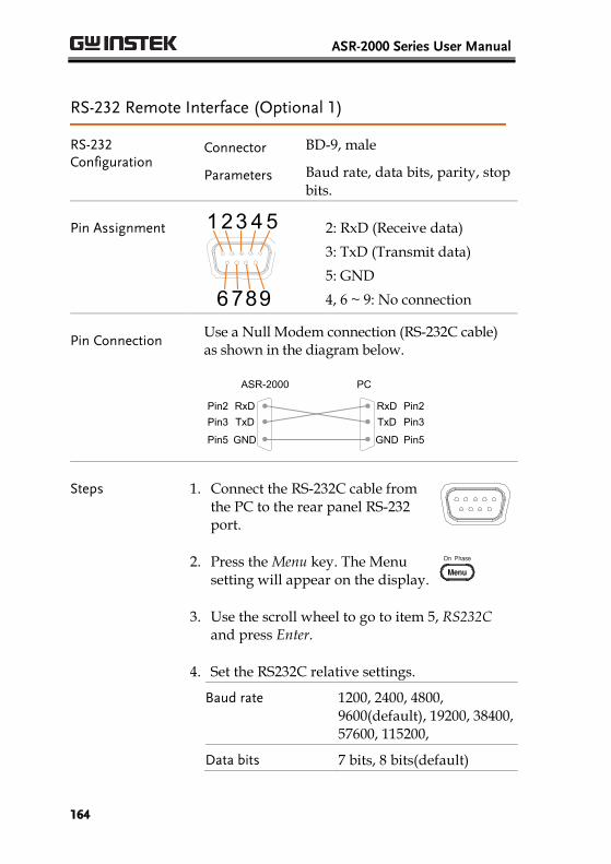
ASR-2000 Series User Manual
164
RS-232 Remote Interface (Optional 1)
RS-232 Configuration
Connector BD-9, male
Parameters Baud rate, data bits, parity, stop bits.
Pin Assignment 123 4 5
6789
2: RxD (Receive data)
3: TxD (Transmit data)
5: GND
4, 6 ~ 9: No connection
Pin Connection Use a Null Modem connection (RS-232C cable) as shown in the diagram below.
ASR-2000 PC
RxDPin2 RxD Pin2
GNDPin5 GND Pin5
TxD Pin3TxDPin3
Steps 1. Connect the RS-232C cable from the PC to the rear panel RS-232 port.
2. Press the Menu key. The Menu setting will appear on the display.
3. Use the scroll wheel to go to item 5, RS232C and press Enter.
4. Set the RS232C relative settings.
Baud rate 1200, 2400, 4800, 9600(default), 19200, 38400, 57600, 115200,
Data bits 7 bits, 8 bits(default)
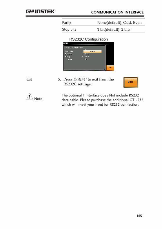
COMMUNICATION INTERFACE
165
Parity None(default), Odd, Even
Stop bits 1 bit(default), 2 bits
RS232C Configuration
Exit 5. Press Exit[F4] to exit from the RS232C settings.
Note The optional 1 interface does Not include RS232 data cable. Please purchase the additional GTL-232 which will meet your need for RS232 connection.
ASR-2000 Series User Manual
166
RS232 Remote Control Function Check
Functionality Check
Invoke a terminal application such as Realterm.
For RS-232, set the COM port, baud rate, stop bit, data bit and parity accordingly.
To check the COM settings in Windows, see the Device Manager. For example, in Win7 go to the Control panel → System → Hardware tab.
Note If you are not familiar with using a terminal application to send/receive remote commands from the serial port, please see page 167 for more information.
Run this query command via the terminal after the instrument has been configured for RS-232 remote control (page 164).
*IDN?
This should return the Manufacturer, Model number, Serial number, and Software version in the following format.
GWINSTEK, ASR-2XXX, GXXXXXXXX, XX.XX.20XXXXXX
Manufacturer: GWINSTEK
Model number : ASR-2XXX
Serial number : GXXXXXXXX
Software version : XX.XX.20XXXXXX
Note For further details, please see the programming manual, available on the GW Instek web site @ www.gwinstek.com.

COMMUNICATION INTERFACE
167
Using Realterm to Establish a Remote Connection
Background Realterm is a terminal program that can be used to communicate with a device attached to the serial port of a PC or via an emulated serial port via USB.
The following instructions apply to version 2.0.0.70. Even though Realterm is used as an example to establish a remote connection, any terminal program can be used that has similar functionality.
Note Realterm can be downloaded on Sourceforge.net free of charge.
For more information please see http://realterm.sourceforge.net/
Operation 1. Download Realterm and install according to the instructions on the Realterm website.
2. Connect the ASR-2000 via USB (page 160) or via RS-232 (page 163).
3. If using RS-232, make note of the configured baud rate, stop bits and parity.
4. Go to the Windows device manager and find the COM port number for the connection. For example, go to the Start menu > Control Panel > Device Manager.
Double click the Ports icon to reveal the connected serial port devices and the COM port for the each connected device.
If using USB, the baud rate, stop bit and parity

ASR-2000 Series User Manual
168
settings can be viewed by right-clicking the connected device and selecting the Properties option.
5. Start Realterm on the PC as an administrator.Click:Start menu>All
Programs>RealTerm>realterm
Tip: to run as an administrator, you can rightclick the Realterm icon in the Windows Startmenu and select the Run as Administratoroption.
6. After Realterm has started, click on the Porttab.
Enter the Baud, Parity, Data bits, Stop bits andPort number configuration for the connection.
The Hardware Flow Control, Software FlowControl options can be left at the defaultsettings.
Press Open to connect to the ASR-2000.

COMMUNICATION INTERFACE
169
Note For USB, the baud rate should be fixed to 115,200.
7. Click on the Send tab.
In the EOL configuration, check on the +LFcheck boxes.
Enter the query:*idn?
Click on Send ASCII.

ASR-2000 Series User Manual
170
8. The terminal display will return the following:
GWINSTEK, ASR-2XXX, GXXXXXXXX,XX.XX.20XXXXXX
(manufacturer, model, serial number, software version)
9. If Realterm fails to connect to the ASR-2000, please check all the cables and settings and try again.
GPIB Remote Interface (Optional 1)
GPIB Configuration
1. Connect a GPIB cable from the PC to the GPIB port on the rear panel.
2. Press the Menu key. The Menusetting will appear on the display.
3. Use the scroll wheel to go to item 6, GPIB and press Enter.
4. Set the GPIB address.
GPIB Address 0 ~ 30 (10 by default)
GPIB Configuration
Note Only one GPIB address can be used at a time.
COMMUNICATION INTERFACE
171
Exit 5. Press Exit[F4] to exit from theGPIB settings.
GPIB Constraints Maximum 15 devices altogether, 20m
cable length, 2m between each device
Unique address assigned to each device
At least 2/3 of the devices turned On
No loop or parallel connection
Note The optional 1 interface does Not include GPIB data cable. Please purchase the additional GTL-258 which will meet your need for GPIB connection.
GPIB Function Check
Functionality Check
Please use the National Instruments Measurement & Automation Controller software to confirm GPIB/LAN functionality.
See the National Instrument website, http://www.ni.com for details.
Operation 1. Start the NI Measurement andAutomation Explorer (MAX)program. Using Windows, press:
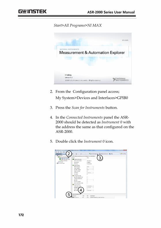
ASR-2000 Series User Manual
172
Start>All Programs>NI MAX
2. From the Configuration panel access;
My System>Devices and Interfaces>GPIB0
3. Press the Scan for Instruments button.
4. In the Connected Instruments panel the ASR-2000 should be detected as Instrument 0 withthe address the same as that configured on theASR-2000.
5. Double click the Instrument 0 icon.
3
2
4
3
5
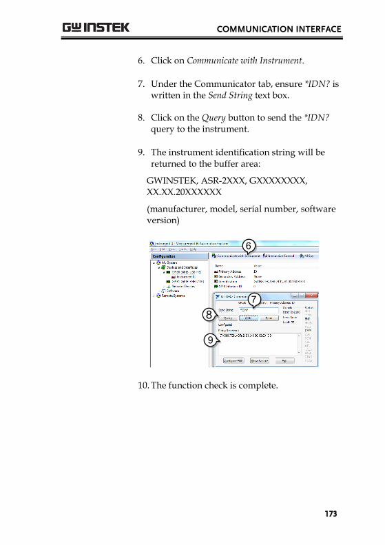
COMMUNICATION INTERFACE
173
6. Click on Communicate with Instrument.
7. Under the Communicator tab, ensure *IDN? iswritten in the Send String text box.
8. Click on the Query button to send the *IDN?query to the instrument.
9. The instrument identification string will bereturned to the buffer area:
GWINSTEK, ASR-2XXX, GXXXXXXXX,XX.XX.20XXXXXX
(manufacturer, model, serial number, software version)
9
6
78
10. The function check is complete.

ASR-2000 Series User Manual
174
Web Server Remote Control Function Check
Functionality Check
Enter the IP address of the power supply (for example: http:// XXX.XXX.XXX.XXX) in a web browser after the instrument has been configured for LAN (page 160).
The web interface allows you to:
View the system and information and thenetwork configuration.
View the analog control pinout.
View the dimensions of the unit.
View the operating area
Example:
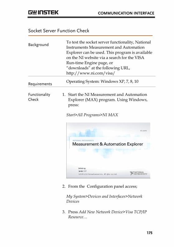
COMMUNICATION INTERFACE
175
Socket Server Function Check
Background To test the socket server functionality, National Instruments Measurement and Automation Explorer can be used. This program is available on the NI website via a search for the VISA Run-time Engine page, or “downloads” at the following URL, http://www.ni.com/visa/
Requirements Operating System: Windows XP, 7, 8, 10
Functionality Check
1. Start the NI Measurement and AutomationExplorer (MAX) program. Using Windows,press:
Start>All Programs>NI MAX
2. From the Configuration panel access;
My System>Devices and Interfaces>NetworkDevices
3. Press Add New Network Device>Visa TCP/IPResource…

ASR-2000 Series User Manual
176
2
3
4. Select Manual Entry of Raw Socket from thepopup window.
4
5. Enter the IP address and the port number ofthe ASR-2000. The port number is fixed at2268.
6. Double click the Validate button and pressNext.
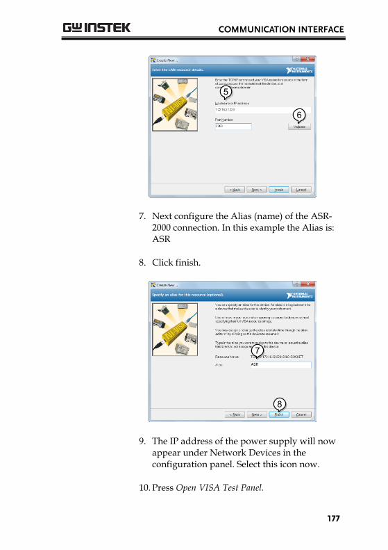
COMMUNICATION INTERFACE
177
5
6
7. Next configure the Alias (name) of the ASR-2000 connection. In this example the Alias is:ASR
8. Click finish.
7
8
9. The IP address of the power supply will nowappear under Network Devices in theconfiguration panel. Select this icon now.
10. Press Open VISA Test Panel.

ASR-2000 Series User Manual
178
9
10
11. Click the Configuration Icon. Under the IOSettings tab check Enable Termination Character.The termination character should be set as LineFeed -\n.
11
12. Click the Input/Output icon. Under the BasicI/O tab, make sure *IDN?\n is entered in theSelect or Enter Command drop box.
13. Click Query.
The ASR-2000 will return the machineidentification string into the buffer area:
GWINSTEK, ASR-2XXX, GXXXXXXXX,XX.XX.20XXXXXX
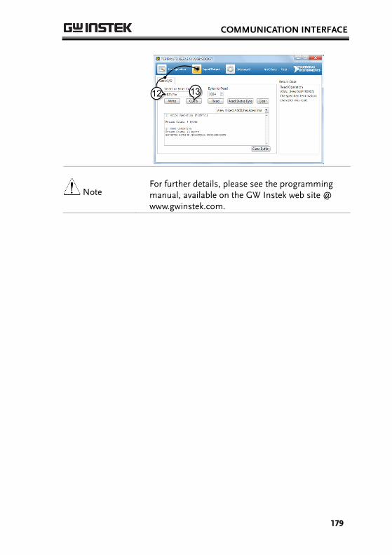
COMMUNICATION INTERFACE
179
1312
Note For further details, please see the programming manual, available on the GW Instek web site @ www.gwinstek.com.

ASR-2000 Series User Manual
180
FAQ
• The accuracy does not match the specification.
• How frequently should the power source be calibrated?
• Is it proper to combine 2 or 3 units to reach 1P3W or 3P4W output?
The accuracy does not match the specification.
Make sure the device is powered On for at least 30 minutes, within +18°C~+28°C. This is necessary to stabilize the unit to match thespecification.
How frequently should the power source be calibrated?
The ASR-2000 should be calibrated by an authorized service center at least every 2 years.
For details regarding calibration, contact your local dealer or GWInstek.
Is it proper to combine 2 or 3 units to reach the 1P3W or
3P4W output?
Not available. ASR-2000 doesn’t support 1P3W or 3P4W output function. Only support 1P2W output type.
For more information, contact your local dealer or GWInstek at www.gwinstek.com / [email protected].
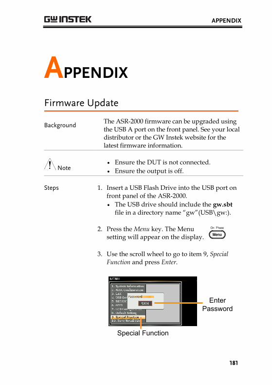
APPENDIX
181
APPENDIX
Firmware Update
Background The ASR-2000 firmware can be upgraded using the USB A port on the front panel. See your local distributor or the GW Instek website for the latest firmware information.
Note Ensure the DUT is not connected.
Ensure the output is off.
Steps 1. Insert a USB Flash Drive into the USB port on front panel of the ASR-2000.
The USB drive should include the gw.sbt
file in a directory name “gw”(USB\gw:).
2. Press the Menu key. The Menusetting will appear on the display.
3. Use the scroll wheel to go to item 9, Special Function and press Enter.
Special Function
EnterPassword

ASR-2000 Series User Manual
182
4. Key in the password when prompted and thenpress Enter.
The password is “5004”.
5. Go to Item 1, Update Firmware and press Enter.
Update Firmware
Exit [F4]
Exit Press Exit[F4] to exit from the Update Firmware settings.
6. Wait for the unit to update. Upon completionthe unit will automatically reboot.

APPENDIX
183
Factory Default Settings The following default settings are the factory configuration settings for the ASR-2000 series. For details on how to return to the factory default settings, see page 46.
AC+DC-INT Mode ASR-2050 ASR-2050R ASR-2100 ASR-2100R
Range 100V Wave Shape SIN ACV 0.0 Vrms DCV +0.0 VdcFREQ 50.00 HzIRMS 5.25 A 10.50 A V Limit +/- 250.0 Vpp F Limit Lo 1.0 Hz F Limit Hi 999.9 Hz IPK Limit +/- 21.00 A +/- 42.00 A ON Phs 0.0o OFF Phs 0.0o
AC-INT Mode ASR-2050 ASR-2050R ASR-2100 ASR-2100R
Range 100V Wave Shape SIN ACV 0.0 Vrms FREQ 50.00 Hz IRMS 5.25 A 10.50 A V Limit 175.0 Vrms F Limit Lo 40.0 Hz F Limit Hi 999.9 Hz IPK Limit +/- 21.00 A +/- 42.00 A ON Phs 0.0o OFF Phs 0.0o
DC-INT Mode ASR-2050 ASR-2050R ASR-2100 ASR-2100R
Range 100V DCV 0.0 Vdc I 5.25 A 10.50 A V Limit +/- 250.0 Vpp IPK Limit +/- 21.00 A +/- 42.00 A

ASR-2000 Series User Manual
184
AC+DC-EXT Mode ASR-2050 ASR-2050R ASR-2100 ASR-2100R
Range 100V GAIN 100.0 IRMS 5.25 A 10.50 A IPK Limit +/- 21.00 A +/- 42.00 A
AC-EXT Mode ASR-2050 ASR-2050R ASR-2100 ASR-2100R
Range 100V GAIN 100.0 IRMS 5.25 A 10.50 A IPK Limit +/- 21.00 A +/- 42.00 A
AC+DC-ADD Mode ASR-2050 ASR-2050R ASR-2100 ASR-2100R
Range 100V Wave Shape SIN ACV 0.0 Vrms DCV +0.0 VdcGAIN 100.0FREQ 50.00 Hz IRMS 5.25 A 10.50 A V Limit +/- 250.0 Vpp F Limit Lo 1.0 Hz F Limit Hi 999.9 Hz IPK Limit +/- 21.00 A +/- 42.00 A ON Phs 0.0o OFF Phs 0.0o
AC-ADD Mode ASR-2050 ASR-2050R ASR-2100 ASR-2100R
Range 100V Wave Shape SIN ACV 0.0 Vrms GAIN 100.0 FREQ 50.00 Hz IRMS 5.25 A 10.50 A V Limit 175.0 Vrms F Limit Lo 40.0 Hz F Limit Hi 999.9 Hz IPK Limit +/- 21.00 A +/- 42.00 A ON Phs 0.0o OFF Phs 0.0o

APPENDIX
185
AC+DC-SYNC Mode ASR-2050 ASR-2050R ASR-2100 ASR-2100R
Range 100V Wave Shape SIN ACV 0.0 Vrms DCV +0.0 VdcSIG LINEIRMS 5.25 A 10.50 A V Limit +/- 250.0 Vpp F Limit 999.9 Hz IPK Limit +/- 21.00 A +/- 42.00 A ON Phs 0.0o OFF Phs 0.0o
AC-SYNC Mode ASR-2050 ASR-2050R ASR-2100 ASR-2100R
Range 100V Wave Shape SIN ACV 0.0 Vrms SIG LINE IRMS 5.25 A 10.50 A V Limit 175.0 Vrms F Limit 999.9 Hz IPK Limit +/- 21.00 A +/- 42.00 A ON Phs 0.0o OFF Phs 0.0o
Menu ASR-2000
T ipeak, hold(msec) 1 ms Ipkh CLR EXEC Power ON OFF Buzzer ON Remote Sense OFF Slew Rate Mode Slope Output Relay Enable THD Format IEC External Control OFF
LAN ASR-2000
DHCP ON
USB Device ASR-2000
Speed Auto
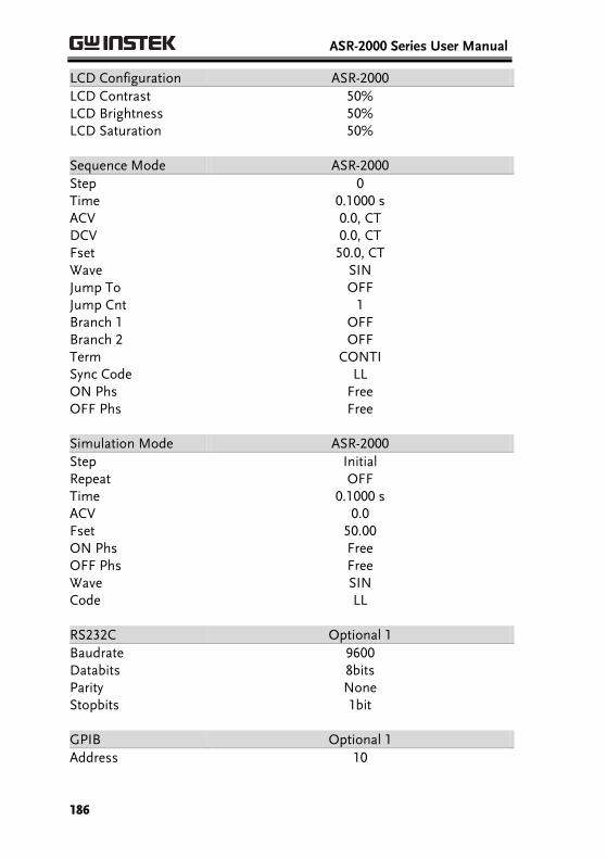
ASR-2000 Series User Manual
186
LCD Configuration ASR-2000
LCD Contrast 50% LCD Brightness 50% LCD Saturation 50%
Sequence Mode ASR-2000
Step 0 Time 0.1000 s ACV 0.0, CT DCV 0.0, CT Fset 50.0, CT Wave SIN Jump To OFF Jump Cnt 1 Branch 1 OFF Branch 2 OFF Term CONTI Sync Code LL ON Phs Free OFF Phs Free
Simulation Mode ASR-2000
Step Initial Repeat OFF Time 0.1000 s ACV 0.0 Fset 50.00 ON Phs Free OFF Phs Free Wave SIN Code LL
RS232C Optional 1
Baudrate 9600 Databits 8bits Parity None Stopbits 1bit
GPIB Optional 1
Address 10

APPENDIX
187
Error Messages & Messages The following error messages or messages may appear on the ASR-2000 screen display during varied operations.
Error Messages Description Protection type Over Ipeak+ Current Positive output current peak value
is excessive. Press "Shift + Cancel" to clear this alarm.
Output Off
Over Ipeak- Current Negative output current peak value is excessive. Press "Shift + Cancel" to clear this alarm.
Output Off
Overheat Internal power stage over heat. Press "Shift + Cancel" to clear this alarm. Check if operating temperature is suitable and if filter is clogged.
Output Off
Over Irms Current Output current RMS value is excessive. Press "Irms" to check allowance set range
Output Off
Power Input Anomaly The power input voltage is insufficient or turning off main power switch. Check input power before rebooting the unit.
System Lock
Fan Failure Fan failure. Contact service center. System Lock
Output Over-Power Over internal power stage maximum power (110% of rating power), press "Shift + Cancel" to clear this alarm.
Output Off
Output Short Call attention to output terminal short status
Output Off
Output Overvoltage Over internal maximum voltage (110% of rating voltage). Press "Shift + Cancel" to clear this alarm.
Output Off
Calibration Data Error The calibration data is abnormal or out of allowance range. Contact service center.
Output Off
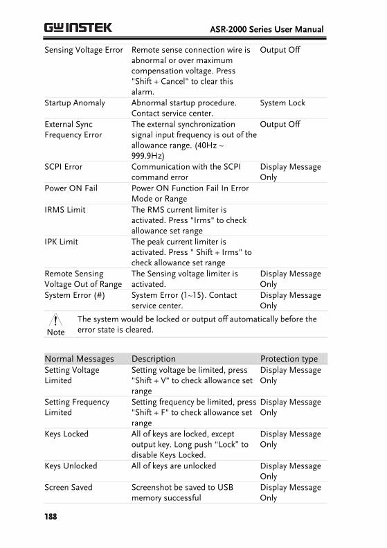
ASR-2000 Series User Manual
188
Sensing Voltage Error Remote sense connection wire is abnormal or over maximum compensation voltage. Press "Shift + Cancel" to clear this alarm.
Output Off
Startup Anomaly Abnormal startup procedure. Contact service center.
System Lock
External Sync Frequency Error
The external synchronization signal input frequency is out of the allowance range. (40Hz ~ 999.9Hz)
Output Off
SCPI Error Communication with the SCPI command error
Display Message Only
Power ON Fail Power ON Function Fail In Error Mode or Range
IRMS Limit The RMS current limiter is activated. Press "Irms" to check allowance set range
IPK Limit The peak current limiter is activated. Press " Shift + Irms" to check allowance set range
Remote Sensing Voltage Out of Range
The Sensing voltage limiter is activated.
Display Message Only
System Error (#) System Error (1~15). Contact service center.
Display Message Only
Note
The system would be locked or output off automatically before the error state is cleared.
Normal Messages Description Protection type Setting Voltage Limited
Setting voltage be limited, press "Shift + V" to check allowance set range
Display Message Only
Setting Frequency Limited
Setting frequency be limited, press "Shift + F" to check allowance set range
Display Message Only
Keys Locked All of keys are locked, except output key. Long push “Lock” to disable Keys Locked.
Display Message Only
Keys Unlocked All of keys are unlocked Display Message Only
Screen Saved Screenshot be saved to USB memory successful
Display Message Only
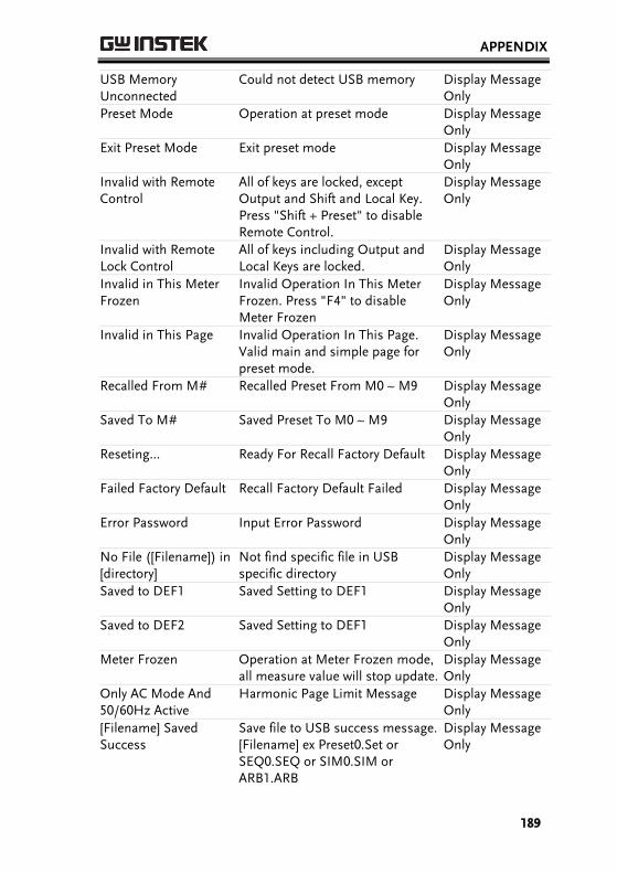
APPENDIX
189
USB Memory Unconnected
Could not detect USB memory Display Message Only
Preset Mode Operation at preset mode Display Message Only
Exit Preset Mode Exit preset mode Display Message Only
Invalid with Remote Control
All of keys are locked, except Output and Shift and Local Key. Press "Shift + Preset" to disable Remote Control.
Display Message Only
Invalid with Remote Lock Control
All of keys including Output and Local Keys are locked.
Display Message Only
Invalid in This Meter Frozen
Invalid Operation In This Meter Frozen. Press "F4" to disable Meter Frozen
Display Message Only
Invalid in This Page Invalid Operation In This Page. Valid main and simple page for preset mode.
Display Message Only
Recalled From M# Recalled Preset From M0 ~ M9 Display Message Only
Saved To M# Saved Preset To M0 ~ M9 Display Message Only
Reseting... Ready For Recall Factory Default Display Message Only
Failed Factory Default Recall Factory Default Failed Display Message Only
Error Password Input Error Password Display Message Only
No File ([Filename]) in [directory]
Not find specific file in USB specific directory
Display Message Only
Saved to DEF1 Saved Setting to DEF1 Display Message Only
Saved to DEF2 Saved Setting to DEF1 Display Message Only
Meter Frozen Operation at Meter Frozen mode, all measure value will stop update.
Display Message Only
Only AC Mode And 50/60Hz Active
Harmonic Page Limit Message Display Message Only
[Filename] Saved Success
Save file to USB success message. [Filename] ex Preset0.Set or SEQ0.SEQ or SIM0.SIM or ARB1.ARB
Display Message Only
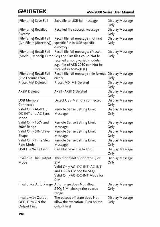
ASR-2000 Series User Manual
190
[Filename] Save Fail Save file to USB fail message Display Message Only
[Filename] Recalled Success
Recalled file success message Display Message Only
[Filename] Recall Fail (No File in [directory])
Recall file fail message (not find specific file in USB specific directory)
Display Message Only
[Filename] Recall Fail (Model ([Model]) Error
Recall file fail message. (Preset, Seq and Sim files could Not be recalled among varied models, e.g., file of ASR-2050 can Not berecalled in ASR-2100.)
Display Message Only
[Filename] Recall Fail (File Format Error)
Recall file fail message (file format error)
Display Message Only
Preset M# Deleted Preset M0~M9 Deleted Display Message Only
ARB# Deleted ARB1~ARB16 Deleted Display Message Only
USB Memory Connected
Detect USB Memory connected Display Message Only
Valid Only AC-INT, DC-INT and AC-Sync Mode
Remote Sense Setting Limit Message
Display Message Only
Valid Only 100V and 200V Range
Remote Sense Setting Limit Message
Display Message Only
Valid Only SIN Wave Shape
Remote Sense Setting Limit Message
Display Message Only
Valid Only Time Slew Rate Mode
Remote Sense Setting Limit Message
Display Message Only
USB File Write Error! Can Not Save File to USB Display Message Only
Invalid in This Output Mode
This mode not support SEQ or SIM Valid Only AC+DC-INT, AC-INT and DC-INT Mode for SEQ Valid Only AC+DC-INT Mode for SIM
Display Message Only
Invalid For Auto Range Auto range does Not allow SEQ/SIM, change the output range
Display Message Only
Invalid with Output OFF, Turn ON the Output First
The output off state does Not allow the execution. Turn on the output first
Display Message Only

APPENDIX
191
Invalid with Output ON, Turn OFF the Output First
The output on state does Not allow the execution. Turn off the output first
Display Message Only
Invalid in This Sequence
Invalid Operation In This Sequence
Display Message Only
SEQ# Deleted SEQ0~SEQ9 Deleted Display Message Only
SIM# Deleted SIM0~SIM9 Deleted Display Message Only
Cleared SEQ# Cleared SEQ0~SEQ9 Display Message Only
Cleared SIM# Cleared SIM0~SIM9 Display Message Only
Recalled from SEQ# %s is File Name , ex SEQ0~SEQ9 or SIM0~SIM9
Display Message Only
Recalled from SIM# Recalled from SIM0 ~ SIM9 Display Message Only
Recall Fail! SEQ0 ~ SEQ9 or SIM0 ~ SIM9 Recall Fail!
Display Message Only
Saved to SEQ# Saved to SEQ0 ~ SEQ9 Display Message Only
Saved to SIM# Saved to SIM0 ~ SIM9 Display Message Only
Save Fail! SEQ0 ~ SEQ9 or SIM0 ~ SIM9 save Fail!
Display Message Only
Sequence preparation...
Sequence preparation, please wait some time
Display Message Only
Sequence is ready. Sequence is ready. Display Message Only
Simulation preparation...
Simulation preparation, please wait some time
Display Message Only
Simulation is ready. Simulation is ready. Display Message Only
Save All Data Ready to save all data (Preset0~9 + SEQ0~9 + SIM0~9 + ARB1~16)
Display Message Only
All Data Saved Success All data are saved successfully (Preset0~9 + SEQ0~9 + SIM0~9 + ARB1~16)
Display Message Only
Recall All Data Ready to recall all data (Preset0~9 + SEQ0~9 + SIM0~9 + ARB1~16)
Display Message Only

ASR-2000 Series User Manual
192
All Data Recall Success All data are recalled successfully (Preset0~9 + SEQ0~9 + SIM0~9 + ARB1~16)
Display Message Only
Delete All Data Ready to delete all data (Preset0~9 + SEQ0~9 + SIM0~9 + ARB1~16)
Display Message Only
All Data Deleted All data are deleted successfully (Preset0~9 + SEQ0~9 + SIM0~9 + ARB1~16)
Display Message Only
Communication Interface Messages
Description Protection type
Rear USB Port Connected To PC
Rear USB port connected to PC Display Message Only
Rear USB Port Disconnected From PC
Rear USB port disconnected from PC
Display Message Only

APPENDIX
193
Specifications The specifications apply when the ASR-2000 is powered on for at least 30 minutes.
Electrical specifications
Model ASR-2050 ASR-2050R
ASR-2100 ASR-2100R
Input ratings (AC rms) Nominal input voltage 100 Vac to 240 Vac
Input voltage range 90 Vac to 264 Vac
Phase Single phase, Two-wire
Nominal input Frequency 50 Hz to 60 Hz
Input frequency range 47 Hz to 63 Hz
Max. power consumption 800 VA or less 1500 VA or less
Power factor*1 100Vac 0.95 (typ.)
200Vac 0.90 (typ.)
Max. input current 100Vac 8 A 15 A
200Vac 4 A 7.5 A
*1 For an output voltage of 100 V/200 V (100V / 200V range), maximum current, and aload power factor of 1.

ASR-2000 Series User Manual
194
Model ASR-2050 ASR-2050R
ASR-2100 ASR-2100R
AC mode output ratings (AC rms)
Voltage
Setting Range*1
0.0 V to 175.0 V / 0.0 V to 350.0 V
Setting Resolution
0.1 V
Accuracy*2 ±(0.5 % of set + 0.6 V / 1.2 V)
Output phase Single phase, Two-wire
Maximum current*3
100 V 5 A 10 A
200 V 2.5 A 5 A
Maximum peak current*4
100 V 20 A 40 A
200 V 10 A 20 A
Load power factor 0 to 1 (leading phase or lagging phase)
Power capacity 500 VA 1000 VA
Frequency Setting range AC Mode: 40.00 Hz to 999.9 Hz, AC+DC Mode: 1.00 Hz to 999.9 Hz
Setting resolution
0.01 Hz (1.00 to 99.99 Hz), 0.1 Hz (100.0 to 999.9 Hz)
Accuracy For 45 Hz to 65 Hz: 0.01% of set For 40 Hz to 999.9 Hz: 0.02% of set
Stability*5 ± 0.005%
Output on/off phase 0.0° to 359.9° variable (setting resolution 0.1°)
DC offset*6 Within ± 20 mV (TYP)
*1 100 V / 200 V range *2 For an output voltage of 17.5 V to 175 V / 35 V to 350 V, sine wave, an output
frequency of 45 Hz to 65 Hz, no load, DC voltage setting 0V (AC+DC mode) and 23°C± 5°C
*3 For an output voltage of 1 V to 100 V / 2 V to 200 V. Limited by the power capacitywhen the output voltage is 100 V to 175 V / 200 V to 350 V.
*4 With respect to the capacitor-input rectifying load. Limited by the maximum current.*5 For 45 Hz to 65 Hz, the rated output voltage, no load and the resistance load for the
maximum current, and the operating temperature.*6 In the case of the AC mode and output voltage setting to 0 V.

APPENDIX
195
Model ASR-2050 ASR-2050R
ASR-2100 ASR-2100R
Output rating for DC mode
Voltage Setting Range*1 -250 V to +250 V / -500 V to +500 V
Setting Resolution
0.1 V
Accuracy*2 ±(|0.5 % of set| + 0.6 V / 1.2 V)
Maximum current*3
100 V 5 A 10 A
200 V 2.5 A 5 A
Maximum peak current*4
100 V 20 A 40 A
200 V 10 A 20 A
Power capacity 500 W 1000 W
*1 100 V / 200 V range *2 For an output voltage of -250 V to -25 V, +25 V to +250 V / -500 V to -50 V, +50 V to
+500 V, no load, AC voltage setting 0V (AC+DC mode) and 23℃ ± 5℃ *3 For an output voltage of 1.4 V to 100 V / 2.8 V to 200 V. Limited by the power capacity
when the output voltage is 100 V to 250 V / 200 V to 500 V.*4 Within 5 ms, Limited by the maximum current.
Model ASR-2050 ASR-2050R
ASR-2100 ASR-2100R
Output voltage stability
Line regulation*1 ±0.2% or less
Load regulation*2 ±0.15% @45 - 65Hz ±0.5% @DC, all other frequencies (0 to 100%, via output terminal)
Ripple noise*3 0.7 Vrms / 1.4 Vrms (TYP)
*1 Power source input voltage is 100 V, 120 V, or 230 V, no load, rated output.*2 For an output voltage of 75 V to 175 V / 150 V to 350 V, a load power factor of 1,
stepwise change from an output current of 0 A to maximum current (or its reverse), using the output terminal on the rear panel.
*3 For 5 Hz to 1 MHz components in DC mode using the output terminal on the rear panel.
Model ASR-2050 ASR-2050R
ASR-2100 ASR-2100R
Output voltage waveform distortion ratio, Output voltage response time, Efficiency
Output voltage waveform distortion ratio*1 0.5 % or less
Output voltage response time*2 100 us (TYP)
Efficiency*3 70 % or more
*1 At an output voltage of 50 V to 175 V / 100 V to 350 V, a load power factor of 1, and inAC and AC+DC mode.
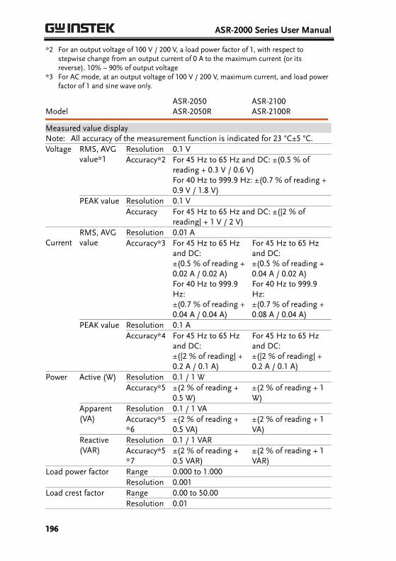
ASR-2000 Series User Manual
196
*2 For an output voltage of 100 V / 200 V, a load power factor of 1, with respect tostepwise change from an output current of 0 A to the maximum current (or its reverse). 10% ~ 90% of output voltage
*3 For AC mode, at an output voltage of 100 V / 200 V, maximum current, and load powerfactor of 1 and sine wave only.
Model ASR-2050 ASR-2050R
ASR-2100 ASR-2100R
Measured value display Note: All accuracy of the measurement function is indicated for 23 °C±5 °C.
Voltage RMS, AVG value*1
Resolution 0.1 V
Accuracy*2 For 45 Hz to 65 Hz and DC: ±(0.5 % of reading + 0.3 V / 0.6 V) For 40 Hz to 999.9 Hz: ±(0.7 % of reading + 0.9 V / 1.8 V)
PEAK value Resolution 0.1 V
Accuracy For 45 Hz to 65 Hz and DC: ±(|2 % of reading| + 1 V / 2 V)
Current RMS, AVG value
Resolution 0.01 A
Accuracy*3 For 45 Hz to 65 Hz and DC: ±(0.5 % of reading + 0.02 A / 0.02 A) For 40 Hz to 999.9 Hz: ±(0.7 % of reading + 0.04 A / 0.04 A)
For 45 Hz to 65 Hz and DC: ±(0.5 % of reading + 0.04 A / 0.02 A) For 40 Hz to 999.9 Hz: ±(0.7 % of reading + 0.08 A / 0.04 A)
PEAK value Resolution 0.1 A
Accuracy*4 For 45 Hz to 65 Hz and DC: ±(|2 % of reading| + 0.2 A / 0.1 A)
For 45 Hz to 65 Hz and DC: ±(|2 % of reading| + 0.2 A / 0.1 A)
Power Active (W) Resolution 0.1 / 1 W
Accuracy*5 ±(2 % of reading + 0.5 W)
±(2 % of reading + 1 W)
Apparent (VA)
Resolution 0.1 / 1 VA
Accuracy*5*6
±(2 % of reading + 0.5 VA)
±(2 % of reading + 1 VA)
Reactive (VAR)
Resolution 0.1 / 1 VAR
Accuracy*5*7
±(2 % of reading + 0.5 VAR)
±(2 % of reading + 1 VAR)
Load power factor Range 0.000 to 1.000
Resolution 0.001
Load crest factor Range 0.00 to 50.00
Resolution 0.01
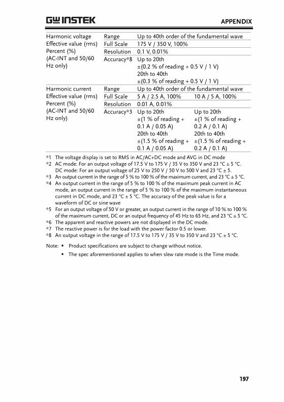
APPENDIX
197
Harmonic voltage Effective value (rms) Percent (%) (AC-INT and 50/60 Hz only)
Range Up to 40th order of the fundamental wave
Full Scale 175 V / 350 V, 100%
Resolution 0.1 V, 0.01%
Accuracy*8 Up to 20th ±(0.2 % of reading + 0.5 V / 1 V) 20th to 40th ±(0.3 % of reading + 0.5 V / 1 V)
Harmonic current Effective value (rms) Percent (%) (AC-INT and 50/60 Hz only)
Range Up to 40th order of the fundamental wave
Full Scale 5 A / 2.5 A, 100% 10 A / 5 A, 100%
Resolution 0.01 A, 0.01%
Accuracy*3 Up to 20th ±(1 % of reading + 0.1 A / 0.05 A) 20th to 40th ±(1.5 % of reading + 0.1 A / 0.05 A)
Up to 20th ±(1 % of reading + 0.2 A / 0.1 A) 20th to 40th ±(1.5 % of reading + 0.2 A / 0.1 A)
*1 The voltage display is set to RMS in AC/AC+DC mode and AVG in DC mode*2 AC mode: For an output voltage of 17.5 V to 175 V / 35 V to 350 V and 23 °C ± 5 °C.
DC mode: For an output voltage of 25 V to 250 V / 50 V to 500 V and 23 °C ± 5. *3 An output current in the range of 5 % to 100 % of the maximum current, and 23 °C ± 5 °C. *4 An output current in the range of 5 % to 100 % of the maximum peak current in AC
mode, an output current in the range of 5 % to 100 % of the maximum instantaneouscurrent in DC mode, and 23 °C ± 5 °C. The accuracy of the peak value is for a waveform of DC or sine wave
*5 For an output voltage of 50 V or greater, an output current in the range of 10 % to 100 % of the maximum current, DC or an output frequency of 45 Hz to 65 Hz, and 23 °C ± 5 °C.
*6 The apparent and reactive powers are not displayed in the DC mode.*7 The reactive power is for the load with the power factor 0.5 or lower. *8 An output voltage in the range of 17.5 V to 175 V / 35 V to 350 V and 23 °C ± 5 °C.
Note: Product specifications are subject to change without notice.
The spec aforementioned applies to when slew rate mode is the Time mode.
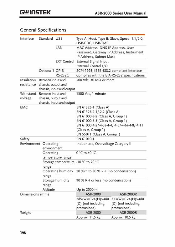
ASR-2000 Series User Manual
198
General Specifications
Interface Standard USB Type A: Host, Type B: Slave, Speed: 1.1/2.0, USB-CDC, USB-TMC
LAN MAC Address, DNS IP Address, User Password, Gateway IP Address, Instrument IP Address, Subnet Mask
EXT Control External Signal Input External Control I/O
Optional 1 GPIB SCPI-1993, IEEE 488.2 compliant interface
RS-232C Complies with the EIA-RS-232 specifications
Insulation resistance
Between input and chassis, output and chassis, input and output
500 Vdc, 30 MΩ or more
Withstand voltage
Between input and chassis, output and chassis, input and output
1500 Vac, 1 minute
EMC EN 61326-1 (Class A) EN 61326-2-1/-2-2 (Class A) EN 61000-3-2 (Class A, Group 1) EN 61000-3-3 (Class A, Group 1) EN 61000-4-2/-4-3/-4-4/-4-5/-4-6/-4-8/-4-11 (Class A, Group 1) EN 55011 (Class A, Group1)
Safety EN 61010-1
Environment Operating environment
Indoor use, Overvoltage Category II
Operating temperature range
0 °C to 40 °C
Storage temperature range
-10 °C to 70 °C
Operating humidity range
20 %rh to 80 % RH (no condensation)
Storage humidity range
90 % RH or less (no condensation)
Altitude Up to 2000 m
Dimensions (mm) ASR-2000 ASR-2000R
285(W)×124(H)×480(D) (not includingprotrusions)
213(W)×124(H)×480(D) (not includingprotrusions)
Weight ASR-2000 ASR-2000R
Approx. 11.5 kg Approx. 10.5 kg
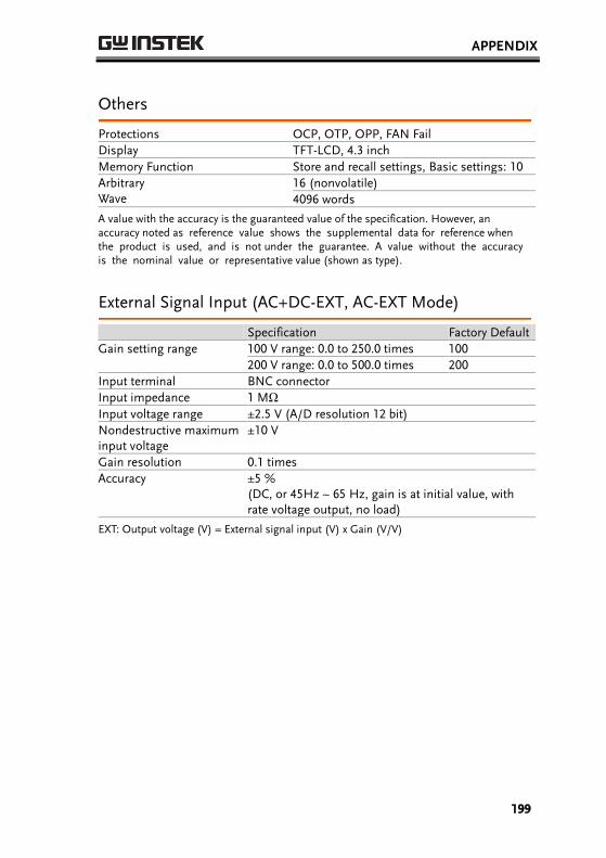
APPENDIX
199
Others
Protections OCP, OTP, OPP, FAN Fail
Display TFT-LCD, 4.3 inch
Memory Function Store and recall settings, Basic settings: 10
Arbitrary Wave
16 (nonvolatile)
4096 words
A value with the accuracy is the guaranteed value of the specification. However, an accuracy noted as reference value shows the supplemental data for reference when the product is used, and is not under the guarantee. A value without the accuracy is the nominal value or representative value (shown as type).
External Signal Input (AC+DC-EXT, AC-EXT Mode)
Specification Factory Default
Gain setting range 100 V range: 0.0 to 250.0 times 100
200 V range: 0.0 to 500.0 times 200
Input terminal BNC connector
Input impedance 1 MΩ
Input voltage range ±2.5 V (A/D resolution 12 bit)
Nondestructive maximum input voltage
±10 V
Gain resolution 0.1 times
Accuracy ±5 % (DC, or 45Hz ~ 65 Hz, gain is at initial value, with rate voltage output, no load)
EXT: Output voltage (V) = External signal input (V) x Gain (V/V)
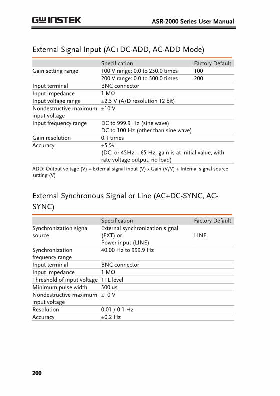
ASR-2000 Series User Manual
200
External Signal Input (AC+DC-ADD, AC-ADD Mode)
Specification Factory Default
Gain setting range 100 V range: 0.0 to 250.0 times 100
200 V range: 0.0 to 500.0 times 200
Input terminal BNC connector
Input impedance 1 MΩ
Input voltage range ±2.5 V (A/D resolution 12 bit)
Nondestructive maximum input voltage
±10 V
Input frequency range DC to 999.9 Hz (sine wave) DC to 100 Hz (other than sine wave)
Gain resolution 0.1 times
Accuracy ±5 % (DC, or 45Hz ~ 65 Hz, gain is at initial value, with rate voltage output, no load)
ADD: Output voltage (V) = External signal input (V) x Gain (V/V) + Internal signal source setting (V)
External Synchronous Signal or Line (AC+DC-SYNC, AC-
SYNC)
Specification Factory Default
Synchronization signal source
External synchronization signal (EXT) or Power input (LINE)
LINE
Synchronization frequency range
40.00 Hz to 999.9 Hz
Input terminal BNC connector
Input impedance 1 MΩ
Threshold of input voltage TTL level
Minimum pulse width 500 us
Nondestructive maximum input voltage
±10 V
Resolution 0.01 / 0.1 Hz
Accuracy ±0.2 Hz
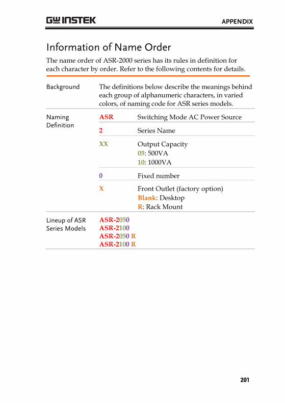
APPENDIX
201
Information of Name Order The name order of ASR-2000 series has its rules in definition for each character by order. Refer to the following contents for details.
Background The definitions below describe the meanings behind each group of alphanumeric characters, in varied colors, of naming code for ASR series models.
Naming Definition
ASR Switching Mode AC Power Source
2 Series Name
XX Output Capacity
05: 500VA
10: 1000VA
0 Fixed number
X Front Outlet (factory option)
Blank: Desktop
R: Rack Mount
Lineup of ASR Series Models
ASR-2050 ASR-2100 ASR-2050 R ASR-2100 R

ASR-2000 Series User Manual
202
ASR-2000 Dimensions
ASR-2100/2050
Scale = mm

APPENDIX
203
ASR-2100R/2050R
Scale = mm

ASR-2000 Series User Manual
204
ASR-2100R/2050R with GET Series Box
Scale = mm
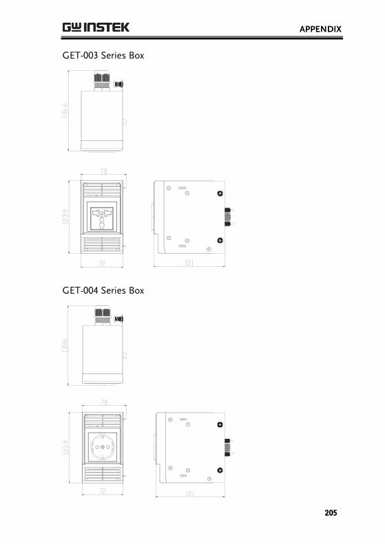
APPENDIX
205
GET-003 Series Box
GET-004 Series Box
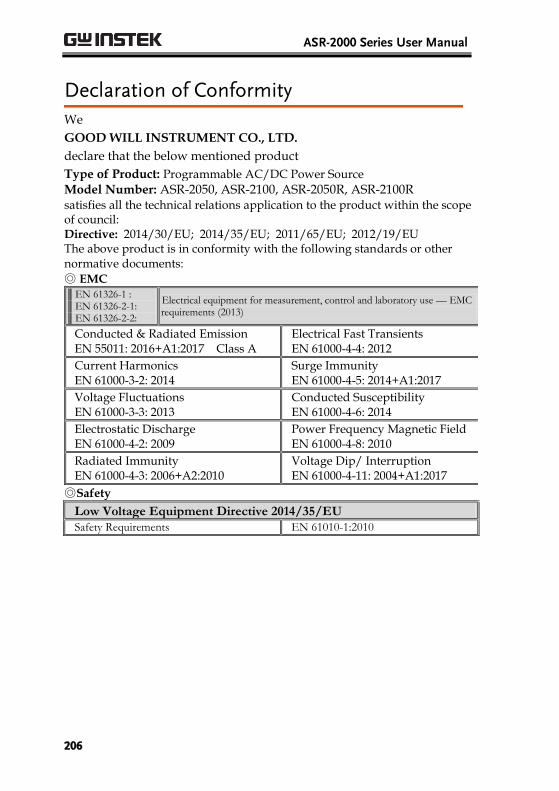
ASR-2000 Series User Manual
206
Declaration of Conformity
We
GOOD WILL INSTRUMENT CO., LTD.
declare that the below mentioned product
Type of Product: Programmable AC/DC Power Source Model Number: ASR-2050, ASR-2100, ASR-2050R, ASR-2100R satisfies all the technical relations application to the product within the scope of council: Directive: 2014/30/EU; 2014/35/EU; 2011/65/EU; 2012/19/EU The above product is in conformity with the following standards or other normative documents:
◎ EMCEN 61326-1 : EN 61326-2-1: EN 61326-2-2:
Electrical equipment for measurement, control and laboratory use –– EMC requirements (2013)
Conducted & Radiated Emission EN 55011: 2016+A1:2017 Class A
Electrical Fast Transients EN 61000-4-4: 2012
Current Harmonics EN 61000-3-2: 2014
Surge Immunity EN 61000-4-5: 2014+A1:2017
Voltage Fluctuations EN 61000-3-3: 2013
Conducted Susceptibility EN 61000-4-6: 2014
Electrostatic Discharge EN 61000-4-2: 2009
Power Frequency Magnetic Field EN 61000-4-8: 2010
Radiated Immunity EN 61000-4-3: 2006+A2:2010
Voltage Dip/ Interruption EN 61000-4-11: 2004+A1:2017
◎Safety
Low Voltage Equipment Directive 2014/35/EU Safety Requirements EN 61010-1:2010

APPENDIX
207
Maintenance & Regular Inspection
Background The potential malfunctions and faults may occur on ASR-2000 due to scores of reasons like humidity, temperature, dust, vibration as well as aging and wear of components. Consequently, to conduct regular maintenance and inspection on ASR-2000 is highly suggested on daily basis.
Note
The maintenance and inspection can only be performed by qualified and authorized technician or personnel.
Regular Inspection
Background To achieve a systematically regular inspection, the daily operating data, parameter-relevant records, among other critical information should be well taken down for the establishment of thorough application files for ASR-2000.
Object Item Method
Operating Environment Inspection
Temperature & Humidity
Use both thermometer and hygrometer to check if ambient temperature is lower than 40°C and if the requirement of humidity is well met at all times.
Moisture, Dust & Leak
Observe and make sure no dust bunnies, nor water leak traces and condensation occur.
Gas Leak To sniff if there is any abnormal odor or color existed.

ASR-2000 Series User Manual
208
Equipment
Vibration Check if the equipment is operating stably and free from any vibration.
Heating & Cooling
From the wind hole check if the fan runs adequately and make sure both wind speed and wind volume are in normal status.
Noise Ensure that no abnormal noise does happen.
Maintenance
Calibration Before shipping, we confirm that the proper calibration procedure was implemented in each unit. Nevertheless, in order to maintain the highest performance, we strongly suggest that the periodic calibration is necessary. Contact your dealer or local distributor for calibration.
Cleaning Gently wipe the unit by a soft cloth dipped with neutral diluted detergent when the unit is in need of cleaning. Avoid using volatile chemicals, e.g., benzene, in that some irreversible resultsmay occur as follows.
Discolored surface
Printed characters erased
Clouded display
Note
Before maintenance jobs, it is imperative to turn Off the power switch and remove the power cord from the unit as possible electric shock, which leads to injury or death, may occur if not doing so.
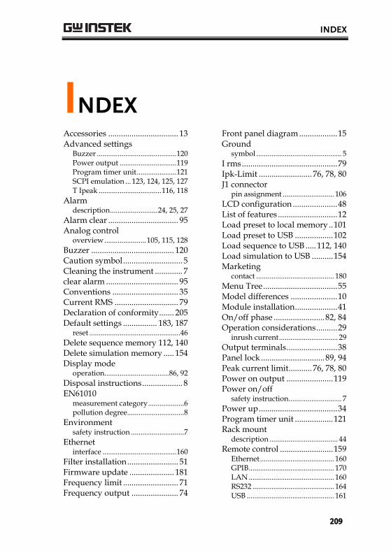
INDEX
209
INDEXAccessories ................................. 13 Advanced settings
Buzzer .......................................... 120 Power output .............................. 119 Program timer unit ..................... 121 SCPI emulation ... 123, 124, 125, 127 T Ipeak ................................. 116, 118
Alarm description ......................... 24, 25, 27
Alarm clear ................................. 95 Analog control
overview ...................... 105, 115, 128
Buzzer ....................................... 120 Caution symbol ............................ 5 Cleaning the instrument ............. 7 clear alarm .................................. 95 Conventions ............................... 35 Current RMS .............................. 79 Declaration of conformity ....... 205 Default settings ................ 183, 187
reset ................................................46
Delete sequence memory 112, 140 Delete simulation memory ..... 154 Display mode
operation .................................. 86, 92
Disposal instructions ................... 8 EN61010
measurement category ...................6 pollution degree ..............................8
Environment safety instruction ............................7
Ethernet interface ....................................... 160
Filter installation ........................ 51 Firmware update ..................... 181 Frequency limit .......................... 71 Frequency output ...................... 74
Front panel diagram .................. 15 Ground
symbol ............................................. 5
I rms ............................................. 79 Ipk-Limit ......................... 76, 78, 80 J1 connector
pin assignment ........................... 106
LCD configuration ..................... 48 List of features ............................ 12 Load preset to local memory .. 101 Load preset to USB .................. 102 Load sequence to USB ..... 112, 140 Load simulation to USB .......... 154 Marketing
contact ......................................... 180
Menu Tree ................................... 55 Model differences ...................... 10 Module installation .................... 41 On/off phase ........................ 82, 84 Operation considerations .......... 29
inrush current ............................... 29
Output terminals ........................ 38 Panel lock .............................. 89, 94 Peak current limit ........... 76, 78, 80 Power on output ...................... 119 Power on/off
safety instruction ............................ 7
Power up ..................................... 34 Program timer unit .................. 121 Rack mount
description .................................... 44
Remote control ......................... 159 Ethernet ....................................... 160 GPIB ............................................. 170 LAN ............................................. 160 RS232 ........................................... 164 USB .............................................. 161

ASR-2000 Series User Manual
210
Remote control function check GPIB ............................................. 171 Realterm ...................................... 167 RS-232 .................................. 163, 166 USB ...................................... 163, 166
Save preset to local memory .. 100 Save preset to USB ................... 102 Save sequence to USB ......112, 140 Save simulation to USB........... 154 SCPI emulation . 123, 124, 125, 127 Serial number
view ............................................... 47
Service operation about disassembly .......................... 6 contact .......................................... 180
Signal output pin assignment ........................... 110
Socket server function check .. 175 Start/stop phase .................. 82, 84 SYNC output
pin assignment ........................... 108
System version
view ............................................... 47
T Ipeak............................... 116, 118 Test
Sequence Overview ....................................... 129 Recall.............................................. 139 Run ................................................. 143 Save ................................................ 139 Settings .......................................... 134
Simulation Overview ....................................... 145 Recall.............................................. 153 Run ................................................. 157 Save ................................................ 153 Settings .......................................... 149
Updating the firmware ........... 181 USB driver installation .............. 49 Voltage limit ............................... 65 Voltage output level .. 68, 206, 207 Voltage range ......... 61, 62, 63, 200 Warning symbol .......................... 5 Web server function check ..... 174 Wire gauge chart ........................ 53
Test Equipment Depot - 800.517.8431 - 99 Washington Street Melrose, MA 02176
TestEquipmentDepot.com