Profibus Network Issues
18
Resolving Typical PROFIBUS Network issues using PROFIBUS Tester By BlueBox Communication 1 www.BlueBoxComm.com
-
Upload
bluboxx-communication-pvt-ltd -
Category
Engineering
-
view
474 -
download
0
Transcript of Profibus Network Issues

Resolving Typical PROFIBUS
Network issues using
PROFIBUS Tester
By
BlueBox Communication
1
www.BlueBoxComm.com
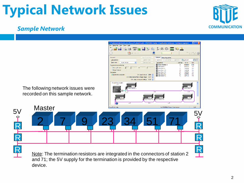
Typical Network Issues
Sample Network
Master
2 7 9 23 34 51 71
RR
R
R R
R
5V
Note: The termination resistors are integrated in the connectors of station 2
and 71; the 5V supply for the termination is provided by the respective
device.
5V
The following network issues were
recorded on this sample network.
2

Typical Network Issues Case 1: Reversal of results from both ends of the system
Case 1:
Step 1:
Connect and test from left end side (Master 2)
Step 2:
Connect and test from right end side (Slave 71)
Result:
Test results from the left end:
- Good quality values for stations 2 - 34
- Bad quality values for stations 51 – 71
Test results from the right side:
- Bad quality values for stations 2 – 34
- Good quality values for stations 51 – 71
Reversal of Q-Levels !
measurement from right side
(Slave 71)
measurement from left side
(Master 2)
3

2 7 9 23 34 51 71
RR
R
R R
R
5V 5VMaster
R
Reason: High Line Resistance between two Stations
(#34 and #51)
Interpretation:
The test result from the right side is the reversal (!) of the test results from the left side and
vice versa.
This kind of reversal is a clear indication for an high resistance in the network.
In this case the problem is caused somewhere between slave 34 and slave 51
e.g. corrosion, sharply bent cable, etc.
Typical Network Issues
Case 1: Reversal of results from both ends of the system
4

Typical Network Issues Case 2: Q-level becomes worse from one measuring point to other
Case 2:
- Step 1: perform test at left end (Master 2)
- Step 2: perform test at right end (Slave 71)
- Step 3: perform tests at random stations located in the middle of the network
Result:
- No reversion of Q-level between left and right side
- Instead, the Q-level for all stations generally declines from one station to the other.
Master 2 Slave 7 Slave 23 Slave 71
5

Interpretation:
- The problem is not caused by resistance problems (corrosion, cable too long, etc…
- The problem is caused by signal reflections in the network,
in this case by a missing termination resistance at Slave 71.
Typically, the problem is located at the test point that shows most stations with a bad Q-
level.
2 7 9 23 34 51 71RR
R
R R
R
5V 5VMaster
You can see the reflections in the oscilloscope
display of master 2 while connected
at test point Slave 71.
Typical Network Issues Case 2: Q-level becomes worse from one measuring point to other
6

Typical Network Issues Case 3: Some stations are “missing”
Case 3:
- Step 1: perform test at left side (Master 2)
- Step 2: perform test at right side (Slave 71)
(Note: make sure that Timeout is not caused by the
time-out setting in PB-T4: => Tools / settings)
Result:
- Test at left end: Slave 53 and 71 are missing
- Test at right end: all stations are missing
7

Interpretation:
The fact that some devices can be seen from one end but not from the other
indicates that the problem is not be caused by the devices themselves.
The test result at the left end shows that the Q-levels are good until slave 34.
After slave 34 the Q-levels are not testable. This indicates that the problem
must be in the line between slave 34 and 51.
Conclusion:
The problem is caused by a break of one or both signal lines.
Master
2 7 9 23 34 51 71
RR
R
R R
R
5V 5V
?
Typical Network Issues Case 3: Some stations are “missing”
8

Typical Network Issues Case 4: Quality Level of one device is bad
Step 1: perform test at left side (Master 2)
Step 2: perform test at right side (Slave 123)
Step 3: perform test at Slave 23
Result:
The Q-level of slave 23 is bad. All others are good. The result of all three measurements is basically
identical.
Interpretation:
The voltage level of RS485 driver of station 23 (and only station 23) is too low.
measurement from left side (master 2)
measurement directly from slave 23
measurement from right side (slave 123)
9

Typical Network Issues
Case 5: Bus-termination is not powered correctly
An idle voltage of approx. 0,6 Volts indicates that only one bus-termination is powered correctly
communication may work, sporadic failures likely
An idle voltage close to 0 Volts (both terminations not correctly powered or one termination missing/one
not correctly powered PROFIBUS will not start
Indication of idle voltage:The correct idle voltage is supposed to be
between 0.8 and 1.4 V.
An idle voltage lower than that indicates that one
or both bus-terminations are not powered
correctly.
In addtion, you can detect a low
idle-voltage in the oscilloscope
(in this case approx. 0.5 V)
1V
10

Typical Network Issues
Case 6: Too many bus-terminations or electrical resistance
R
R
R
2 7 9 23 34 51 71
RR
R
R R
R
5V 5VMaster
11

Typical Failure Cases
Case 6: Too many bus-terminations or electrical resistance
Note: The test results get worse the closer the PBT-4 is connected to the location of
the problem (Master #2).
However, the signal quality level of the problematic station (Master #2) might be one
of the best.
Unfortunately, the test results do not change as strikingly when dealing with tool
many bus-terminations as they do with missing bus-terminations. Additional
resistance usually affects all stations.
signal blurred
only some drops in signal due to reflections
bad signal flanks
12

Typical Network Issues
Case 7: Cable too long for selected baud rate
Note:
Here the built-in Master functionality of the PB-
T4 comes in very handy.
Without changing the PLC-program, the
network can be tested at different baud rates
(e.g. 1.5Mbaud). As shown above, running the
same network at a baud rate of 1,5 Mbaud is
perfectly acceptable.
Note 1:
A cable length of 144m is too long for 12 Mbaud
(100m permissible).
Therefore, the quality levels / signal level of the
stations measured at the master drop with the
distance to the referring slave.
Note 2:
A test performed at the opposite end of the
network (station #17) will show a “mirrored
image”. In contrast to high line resistance the
signal quality degrades gradually.
12 Mbaud, 144m 1.5 Mbaud, 144m
13

Best-Practice for PROFIBUS
Cable type, number of stations, cable length
PROFIBUS RS-485
Layout: terminated line, branch (or stub) lines < 0.3 m (1 foot) !!
Cable type: shielded twisted pair cable acc. to PROFIBUS specification
Number of stations: max. 32 w/o repeater, 127 using repeaters
Max. cable length (applies to cable type A only):
Baud Rate Max. Cable Length
9.6, 19.2, 31.25, and 45.45Kbit/s 1200 m (3940 ft)
93.75 and 187.5 Kbit/s 1000 m (3280 ft)
500 Kbit/s 400 m (1310 ft)
1500 Kbit/s 200 m (656 ft)
3000, 6000, and 12000 Kbit/s 100 m (328 ft)
14
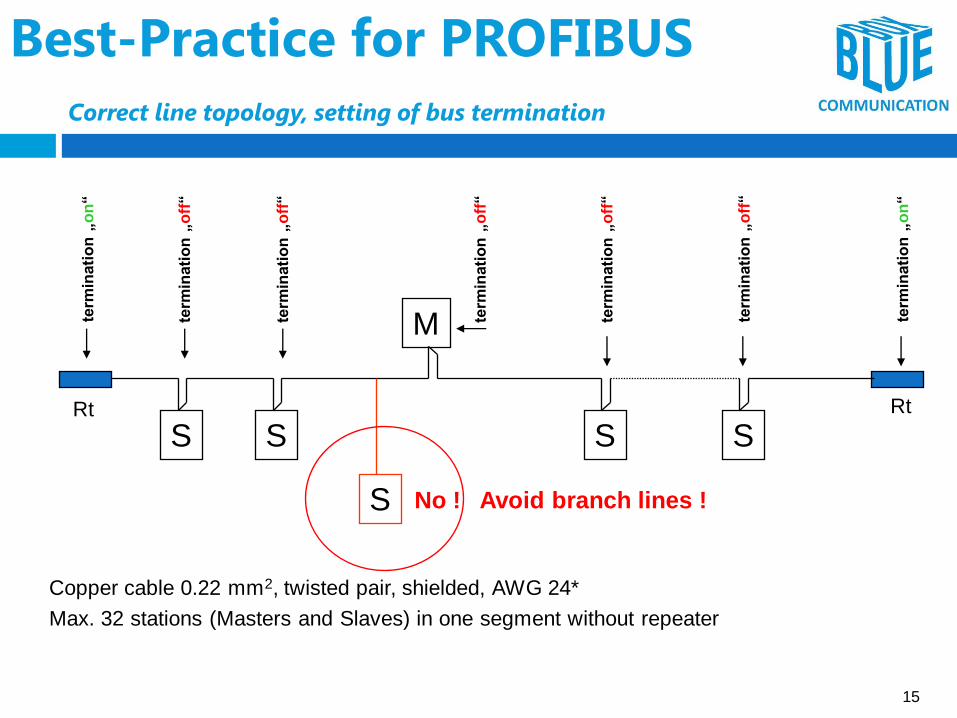
Best-Practice for PROFIBUS
Correct line topology, setting of bus termination
Rt Rt
S S SS
M
S No ! Avoid branch lines !
term
inati
on
„o
n“
term
inati
on
„o
n“
term
inati
on
„o
ff“
term
inati
on
„o
ff“
term
inati
on
„o
ff“
term
inati
on
„o
ff“
term
inati
on
„o
ff“
Copper cable 0.22 mm2, twisted pair, shielded, AWG 24*
Max. 32 stations (Masters and Slaves) in one segment without repeater
15
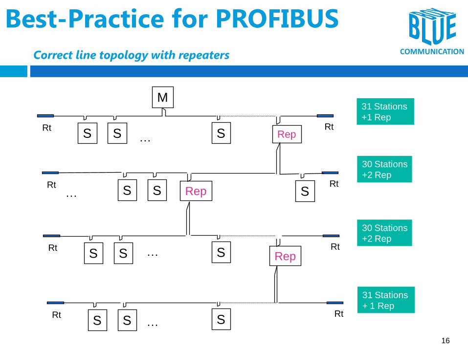
Best-Practice for PROFIBUS
Correct line topology with repeaters
Rt RtS SS
Rt RtS SS
M31 Stations
+1 Rep
30 Stations
+2 Rep
30 Stations
+2 Rep
Rt RtS SS
Rt RtS SS
31 Stations
+ 1 Rep
Rep
Rep
Rep
…
…
…
…
16

Best-Practice for PROFIBUS Grounding and mounting of PROFIBUS RS-485
PROFIBUS
GND Cable to balance the Potentials, approx. 16 mm2,
Best: Same Routing as PROFIBUS Cable (parallel)
Slave SlaveMaster
Equipotential Rail
PROFIBUS
Planar Connection of the PROFIBUS Cable Shielding to the Ground
Potential, e.g. through special Clamps
Equipotential Rail Equipotential Rail
17

www.BlueBoxComm.com
Thank You
BlueBox Communication
443, Nana Peth, Kirad Villa,
Shop No. 5B, Pune- 411002,
Maharashtra, India.
+91 7875218696
+91 7875440101
18