
Product manual FlexPLP IRPLP220 - sluzba.cz · Product documentation, IRC5 3HAW050041018 Revision:-...
112
Product manual FlexPLP IRPLP220
Transcript of Product manual FlexPLP IRPLP220 - sluzba.cz · Product documentation, IRC5 3HAW050041018 Revision:-...

Product manualFlexPLP IRPLP220


Product Manual
FlexPLP IRPLP220
Document ID: 3HAW050041018-001
Revision: -

The information in this manual is subject to change without notice and should not be construed as a commitment by ABB. ABB assumes no responsibility for any errors that may appear in this manual.
Except as may be expressly stated anywhere in this manual, nothing herein shall be construed as any kind of guarantee or warranty by ABB for losses, damages to persons or property, fitness for a specific purpose or the like.
In no event shall ABB be liable for incidental or consequential damages arising from use of this manual and products described herein.
This manual and parts thereof must not be reproduced or copied without ABB’s written permission.
Additional copies of this manual may be obtained from ABB at its then current charge.
"The original language for this publication is English. Any other languages that are supplied have been translated from English"
© Copyright 2015 ABB All rights reserved.
ABB RoboticsCNAUS
Shanghai, China
Table of contents
Overview . . . . . . . . . . . . . . . . . . . . . . . . . . . . . . . . . . . . . . . . . . . . . . . . . . . . . . . . . . . . . . . . . . . . . . . . . . . . . 5Product documentation, IRC5 . . . . . . . . . . . . . . . . . . . . . . . . . . . . . . . . . . . . . . . . . . . . . . . . . . . . . . . . . . . . . 7How to read the product manual. . . . . . . . . . . . . . . . . . . . . . . . . . . . . . . . . . . . . . . . . . . . . . . . . . . . . . . . . . . . 9
1 Safety 11
1.1 Introduction . . . . . . . . . . . . . . . . . . . . . . . . . . . . . . . . . . . . . . . . . . . . . . . . . . . . . . . . . . . . . . . . . . . . . . . 11
1.2 General safety information. . . . . . . . . . . . . . . . . . . . . . . . . . . . . . . . . . . . . . . . . . . . . . . . . . . . . . . . . . . 121.2.1 Safety in the machine controller system. . . . . . . . . . . . . . . . . . . . . . . . . . . . . . . . . . . . . . . . . . . . . 12
1.3 Safety risks . . . . . . . . . . . . . . . . . . . . . . . . . . . . . . . . . . . . . . . . . . . . . . . . . . . . . . . . . . . . . . . . . . . . . . . 131.3.1 Safety risks during installation and service work. . . . . . . . . . . . . . . . . . . . . . . . . . . . . . . . . . . . . . 131.3.2 Safety risks related to tools/workpieces . . . . . . . . . . . . . . . . . . . . . . . . . . . . . . . . . . . . . . . . . . . . . 151.3.3 Safety risks related to pneumatic/hydraulic systems . . . . . . . . . . . . . . . . . . . . . . . . . . . . . . . . . . . 161.3.4 Safety risks during operational disturbances . . . . . . . . . . . . . . . . . . . . . . . . . . . . . . . . . . . . . . . . . 171.3.5 Risks associated with live electric parts . . . . . . . . . . . . . . . . . . . . . . . . . . . . . . . . . . . . . . . . . . . . . 18
1.4 Safety actions related to the FlexPLP . . . . . . . . . . . . . . . . . . . . . . . . . . . . . . . . . . . . . . . . . . . . . . . . . . 191.4.1 Safety fence dimensions . . . . . . . . . . . . . . . . . . . . . . . . . . . . . . . . . . . . . . . . . . . . . . . . . . . . . . . . . 191.4.2 Fire extinguishing. . . . . . . . . . . . . . . . . . . . . . . . . . . . . . . . . . . . . . . . . . . . . . . . . . . . . . . . . . . . . . 201.4.3 Emergency release of the FlexPLP device axes . . . . . . . . . . . . . . . . . . . . . . . . . . . . . . . . . . . . . . . 211.4.4 Brake testing. . . . . . . . . . . . . . . . . . . . . . . . . . . . . . . . . . . . . . . . . . . . . . . . . . . . . . . . . . . . . . . . . . 221.4.5 Safe use of the Teach Pendant Unit . . . . . . . . . . . . . . . . . . . . . . . . . . . . . . . . . . . . . . . . . . . . . . . . 231.4.6 Work inside the FlexPLP's working range . . . . . . . . . . . . . . . . . . . . . . . . . . . . . . . . . . . . . . . . . . . 241.4.7 Translate the information on safety and information labels . . . . . . . . . . . . . . . . . . . . . . . . . . . . . . 25
1.5 Safety stops. . . . . . . . . . . . . . . . . . . . . . . . . . . . . . . . . . . . . . . . . . . . . . . . . . . . . . . . . . . . . . . . . . . . . . . 261.5.1 What is an emergency stop? . . . . . . . . . . . . . . . . . . . . . . . . . . . . . . . . . . . . . . . . . . . . . . . . . . . . . . 26
1.6 Safety related instructions . . . . . . . . . . . . . . . . . . . . . . . . . . . . . . . . . . . . . . . . . . . . . . . . . . . . . . . . . . . 271.6.1 Safety signals in the manual . . . . . . . . . . . . . . . . . . . . . . . . . . . . . . . . . . . . . . . . . . . . . . . . . . . . . . 27
2 Product description 29
2.1 Product overview . . . . . . . . . . . . . . . . . . . . . . . . . . . . . . . . . . . . . . . . . . . . . . . . . . . . . . . . . . . . . . . . . . . 292.2 Terminology . . . . . . . . . . . . . . . . . . . . . . . . . . . . . . . . . . . . . . . . . . . . . . . . . . . . . . . . . . . . . . . . . . . . . . . 30
2.3 Principle structure . . . . . . . . . . . . . . . . . . . . . . . . . . . . . . . . . . . . . . . . . . . . . . . . . . . . . . . . . . . . . . . . . 312.3.1 Modularity . . . . . . . . . . . . . . . . . . . . . . . . . . . . . . . . . . . . . . . . . . . . . . . . . . . . . . . . . . . . . . . . . . . 312.3.2 Axes combinations . . . . . . . . . . . . . . . . . . . . . . . . . . . . . . . . . . . . . . . . . . . . . . . . . . . . . . . . . . . . . 322.3.3 Driving types . . . . . . . . . . . . . . . . . . . . . . . . . . . . . . . . . . . . . . . . . . . . . . . . . . . . . . . . . . . . . . . . . 332.3.4 Vertical axis mounting and cable chain . . . . . . . . . . . . . . . . . . . . . . . . . . . . . . . . . . . . . . . . . . . . . 34
2.4 Performances . . . . . . . . . . . . . . . . . . . . . . . . . . . . . . . . . . . . . . . . . . . . . . . . . . . . . . . . . . . . . . . . . . . . . 352.4.1 FlexPLP IRPLP220 overall specifications . . . . . . . . . . . . . . . . . . . . . . . . . . . . . . . . . . . . . . . . . . . 352.4.2 FlexPLP IRPLP220 motor specifications. . . . . . . . . . . . . . . . . . . . . . . . . . . . . . . . . . . . . . . . . . . . 36
2.5 Dimensions . . . . . . . . . . . . . . . . . . . . . . . . . . . . . . . . . . . . . . . . . . . . . . . . . . . . . . . . . . . . . . . . . . . . . . . 372.5.1 Dimensions one-axis FlexPLP IRPLP220 . . . . . . . . . . . . . . . . . . . . . . . . . . . . . . . . . . . . . . . . . . . 372.5.2 Dimensions two-axes FlexPLP IRPLP220. . . . . . . . . . . . . . . . . . . . . . . . . . . . . . . . . . . . . . . . . . . 392.5.3 Dimensions three-axes FlexPLP IRPLP220. . . . . . . . . . . . . . . . . . . . . . . . . . . . . . . . . . . . . . . . . . 42
2.6 Weight . . . . . . . . . . . . . . . . . . . . . . . . . . . . . . . . . . . . . . . . . . . . . . . . . . . . . . . . . . . . . . . . . . . . . . . . . . . 442.6.1 Weight . . . . . . . . . . . . . . . . . . . . . . . . . . . . . . . . . . . . . . . . . . . . . . . . . . . . . . . . . . . . . . . . . . . . . . 44
3 Unpacking and handling 45
3.1 Pre-requisites for reception. . . . . . . . . . . . . . . . . . . . . . . . . . . . . . . . . . . . . . . . . . . . . . . . . . . . . . . . . . . . 453.2 Unpacking and acceptance . . . . . . . . . . . . . . . . . . . . . . . . . . . . . . . . . . . . . . . . . . . . . . . . . . . . . . . . . . . . 463.3 Handling/lifting . . . . . . . . . . . . . . . . . . . . . . . . . . . . . . . . . . . . . . . . . . . . . . . . . . . . . . . . . . . . . . . . . . . . 48
4 Installation and commissioning 49
4.1 Introduction . . . . . . . . . . . . . . . . . . . . . . . . . . . . . . . . . . . . . . . . . . . . . . . . . . . . . . . . . . . . . . . . . . . . . . . 49
33HAW050008850 Revision: H

Table of contents
4.2 Mechanical installation. . . . . . . . . . . . . . . . . . . . . . . . . . . . . . . . . . . . . . . . . . . . . . . . . . . . . . . . . . . . . . 504.2.1 Introduction . . . . . . . . . . . . . . . . . . . . . . . . . . . . . . . . . . . . . . . . . . . . . . . . . . . . . . . . . . . . . . . . . . 504.2.2 Mounting surface (fastening of the FlexPLP IRPLP220 to the floor plate). . . . . . . . . . . . . . . . . . 514.2.3 Mounting surfaces (fastening of an axis or customer equipment) . . . . . . . . . . . . . . . . . . . . . . . . . 534.2.4 Jogging axes of a unit with FlexPendant . . . . . . . . . . . . . . . . . . . . . . . . . . . . . . . . . . . . . . . . . . . . 544.2.5 Fastening a unit to the floor plate . . . . . . . . . . . . . . . . . . . . . . . . . . . . . . . . . . . . . . . . . . . . . . . . . . 57
4.3 Cabling and control . . . . . . . . . . . . . . . . . . . . . . . . . . . . . . . . . . . . . . . . . . . . . . . . . . . . . . . . . . . . . . . . 604.3.1 Connectors and internal equipment wiring. . . . . . . . . . . . . . . . . . . . . . . . . . . . . . . . . . . . . . . . . . . 604.3.2 Control architecture . . . . . . . . . . . . . . . . . . . . . . . . . . . . . . . . . . . . . . . . . . . . . . . . . . . . . . . . . . . . 614.3.3 Controller capabilities . . . . . . . . . . . . . . . . . . . . . . . . . . . . . . . . . . . . . . . . . . . . . . . . . . . . . . . . . . 624.3.4 Examples of configurations . . . . . . . . . . . . . . . . . . . . . . . . . . . . . . . . . . . . . . . . . . . . . . . . . . . . . . 644.3.5 Configuration files . . . . . . . . . . . . . . . . . . . . . . . . . . . . . . . . . . . . . . . . . . . . . . . . . . . . . . . . . . . . . 70
5 Calibration 71
5.1 Introduction / When to calibrate. . . . . . . . . . . . . . . . . . . . . . . . . . . . . . . . . . . . . . . . . . . . . . . . . . . . . . . . 715.2 Calibration points . . . . . . . . . . . . . . . . . . . . . . . . . . . . . . . . . . . . . . . . . . . . . . . . . . . . . . . . . . . . . . . . . . . 725.3 Fine calibration . . . . . . . . . . . . . . . . . . . . . . . . . . . . . . . . . . . . . . . . . . . . . . . . . . . . . . . . . . . . . . . . . . . . . 745.4 Update of the revolution counters . . . . . . . . . . . . . . . . . . . . . . . . . . . . . . . . . . . . . . . . . . . . . . . . . . . . . . 77
6 Maintenance 81
6.1 Introduction . . . . . . . . . . . . . . . . . . . . . . . . . . . . . . . . . . . . . . . . . . . . . . . . . . . . . . . . . . . . . . . . . . . . . . . 816.2 Maintenance planning. . . . . . . . . . . . . . . . . . . . . . . . . . . . . . . . . . . . . . . . . . . . . . . . . . . . . . . . . . . . . . . . 836.3 Inspection . . . . . . . . . . . . . . . . . . . . . . . . . . . . . . . . . . . . . . . . . . . . . . . . . . . . . . . . . . . . . . . . . . . . . . . . . 846.4 Lubrication . . . . . . . . . . . . . . . . . . . . . . . . . . . . . . . . . . . . . . . . . . . . . . . . . . . . . . . . . . . . . . . . . . . . . . . . 856.5 Driving belt (tension check, adjustment and replacement) . . . . . . . . . . . . . . . . . . . . . . . . . . . . . . . . . . . 876.6 SMB Battery pack replacement . . . . . . . . . . . . . . . . . . . . . . . . . . . . . . . . . . . . . . . . . . . . . . . . . . . . . . . . 916.7 Repair information . . . . . . . . . . . . . . . . . . . . . . . . . . . . . . . . . . . . . . . . . . . . . . . . . . . . . . . . . . . . . . . . . . 92
7 Decommissioning 93
7.1 Decommissioning . . . . . . . . . . . . . . . . . . . . . . . . . . . . . . . . . . . . . . . . . . . . . . . . . . . . . . . . . . . . . . . . . . . 93
8 Reference information 95
8.1 Introduction . . . . . . . . . . . . . . . . . . . . . . . . . . . . . . . . . . . . . . . . . . . . . . . . . . . . . . . . . . . . . . . . . . . . . . . 958.2 Unit conversion. . . . . . . . . . . . . . . . . . . . . . . . . . . . . . . . . . . . . . . . . . . . . . . . . . . . . . . . . . . . . . . . . . . . . 968.3 Bolt, screws, tightening torques . . . . . . . . . . . . . . . . . . . . . . . . . . . . . . . . . . . . . . . . . . . . . . . . . . . . . . . . 978.4 Standard toolkit. . . . . . . . . . . . . . . . . . . . . . . . . . . . . . . . . . . . . . . . . . . . . . . . . . . . . . . . . . . . . . . . . . . . . 988.5 Special tools . . . . . . . . . . . . . . . . . . . . . . . . . . . . . . . . . . . . . . . . . . . . . . . . . . . . . . . . . . . . . . . . . . . . . . . 99
9 Spare parts 101
9.1 Introduction . . . . . . . . . . . . . . . . . . . . . . . . . . . . . . . . . . . . . . . . . . . . . . . . . . . . . . . . . . . . . . . . . . . . . . 1019.2 Spare parts ballscrew type . . . . . . . . . . . . . . . . . . . . . . . . . . . . . . . . . . . . . . . . . . . . . . . . . . . . . . . . . . . 1029.3 Spare parts gear rack type. . . . . . . . . . . . . . . . . . . . . . . . . . . . . . . . . . . . . . . . . . . . . . . . . . . . . . . . . . . . 1049.4 Covers. . . . . . . . . . . . . . . . . . . . . . . . . . . . . . . . . . . . . . . . . . . . . . . . . . . . . . . . . . . . . . . . . . . . . . . . . . . 1059.5 Cables . . . . . . . . . . . . . . . . . . . . . . . . . . . . . . . . . . . . . . . . . . . . . . . . . . . . . . . . . . . . . . . . . . . . . . . . . . . 106
43HAW050008850 Revision: H

Overview
Overview
About this manual
This manual contains instructions and information for:
• the characteristics of the FlexPLP IRPLP220
• mechanical and electrical installation instructions for the FlexPLP IRPLP220
• maintenance instructions for the FlexPLP IRPLP220
• spare parts
Usage
This manual should be used when working during:
• installation, from lifting the FlexPLP IRPLP220 to its work site and securing it to the
foundation, to making it ready for operation
• maintenance work
• repair work.
Who should read this manual?
This manual is intended for:
• installation personnel
• maintenance personnel
• repair personnel.
Prerequisites
A maintenance /repair/ installation craftsman working with an ABB FlexPLP IRPLP220
must:
• be trained by ABB and have the required knowledge of mechanical and electrical
installation/repair/maintenance work.
Organization of chapters
The manual is organized in the following chapters:
Chapter Content
Safety Safety information that must be read through before performing any installation or service work on the FlexPLP IRPLP220. Contains general safety aspects as well as more specific information about how to avoid personal injuries and damage to the product.
Product description Specifications and characteristics of the FlexPLP IRPLP220.
Unpacking and handling Information relative to the steps following the reception of the FlexPLP IRPLP220, until its installation.
Installation and commis-sioning
Required information about lifting and installation of the FlexPLP IRPLP220 and installation of cabling.
Calibration Information about calibration of the system.
53HAW050041018 Revision:-

Overview
References
Revisions
Maintenance Step-by-step procedures that describe how to perform maintenance of the FlexPLP IRPLP220. Based on a maintenance schedule that may be used in the work of planning periodical maintenance.
Decommissioning Environmental information about the FlexPLP IRPLP220.
Reference information Reference information may be useful for the understanding of this manual.
Spare parts List of the spare parts available for the FlexPLP IRPLP220.
Chapter Content
Reference (ABB manuals) Document ID
Product manual - IRC5 Robot Controller 3HAC021313-001
Service Information System - IRC5 3HAC025709-001
Application manual - Additional axes and stand alone controller 3HAC021395-001
Operating manual - IRC5 with FlexPendant 3HAC16590
System Parameters 3HAC17076
Technical reference manual - RAPID Instructions, Functions, Data types
3HAC16581
Revision Description
- First edition
3HAW050041018 Revision:- 6

Product documentation, IRC5
Product documentation, IRC5
Categories for user documentation from ABB Robotics
The user documentation from ABB Robotics is divided into a number of categories.
This listing is based on the type of information in the documents, regardless of whether the
products are standard or optional.
All documents listed can be ordered from ABB on a DVD. The documents listed are valid for
IRC5 robot systems.
Product manuals
All hardware, manipulators and controllers will be delivered with a Product manual that
contains:
• Safety information
• Installation and commissioning (description of mechanical installation, electrical
connections)
• Maintenance (description of all required preventive maintenance procedures
including intervals)
• Repair (description of all recommended repair procedures including spare parts)
• Additional procedures, if any (calibration, decommissioning)
• Reference information (article numbers for documentation referred to in Product
manual, procedures, lists of tools, safety standards)
• Parts list.
• Foldouts or exploded views.
• Circuit diagrams (or references to circuit diagrams).
Technical reference manuals
The technical reference manuals describe the manipulator software in general and contain
relevant reference information.
• RAPID Overview: An overview of the RAPID programming language.
• RAPID Instructions, Functions and Data types: Description of all RAPID
instructions, functions and data types.
• RAPID Kernel: A formal description of the RAPID programming language.
• System parameters: Description of system parameters and configuration workflow.
73HAW050041018 Revision:-

Product documentation, IRC5
Application manuals
Specific applications (for example, software or hardware options) are described in
Application manuals. An application manual can describe one or several applications.
An application manual generally contains information about:
• The purpose of the application (what it does and when it is useful)
• What is included (for example, cables, I/O boards, RAPID instructions, system
parameters)
• How to install included or required hardware.
• How to use the application
• Examples of how to use the application
Operating manuals
The operating manuals describe hands-on handling of the products. The manuals are aimed
at those having first-hand operational contact with the product, that is production cell
operators, programmers, and trouble shooters.
The group of manuals includes:
• Emergency safety information
• General safety information
• Getting started, IRC5 and RobotStudio
• IRC5 with FlexPendant
• RobotStudio
• Introduction to RAPID
• Trouble shooting, for the controller and manipulator.
3HAW050041018 Revision:- 8

How to read the product manual
How to read the product manual
Reading the procedures
The procedures contain references to figures, tools, material and so on. The references are
read as described below.
References to figures
The procedures often include references to components or attachment points located on the
device/controller. The components or attachment points are marked with italic text in the
procedures and completed with a reference to the figure where the current component or
attachment point is shown.
The denomination in the procedure for the component or attachment point corresponds to the
denomination in the referenced figure.
The table below shows an example of a reference to a figure from a step in a procedure.
Reference to required equipment
The procedures often include references to equipment (spare parts, tools, and so on.) required
for the different actions in the procedure. The equipment is marked with italic text in the
procedures and completed with a reference to the section where the equipment is listed with
further information, i.e. article number, dimension.
The denomination in the procedure for the component or attachment point corresponds to the
denomination in the referenced list.
The table below shows an example of a reference to a list of required equipment, from a step
in a procedure.
Safety information
The manual includes a separate safety chapter that must be read through before proceeding
with any service or installation procedures. All procedures also include specific safety
information when dangerous steps are to be performed.
For more information, see Safety on page 11
Action Note/Illustration
8. Remove the rear attachment screws, gearbox.
Shown in the figure Location of gearbox on page xx.
Action Note/Illustration
3. Fit a new sealing, 2 to the gearbox. Art. no. is specified in Required equipment on page xx.
93HAW050041018 Revision:-

How to read the product manual
3HAW050041018 Revision:- 10

1 Safety
1.1. Introduction
1 Safety
1.1. Introduction
Overview
The safety information in this manual is divided in two categories:
• general safety aspects, important to attend to before performing any service work on
the device. These are applicable for all service work and are found in General safety
information on page 12.
• specific safety information, pointed out in the procedure at the moment of the danger.
How to avoid and eliminate the danger is either detailed directly in the procedure, or
further detailed in separate instructions, found in Safety related instructions on page
27.
113HAW050041018 Revision:-

1 Safety
1.2.1. Safety in the machine controller system
1.2 General safety information
1.2.1. Safety in the machine controller system
Validity and responsibility
The information does not cover how to design, install and operate a complete system, nor
does it cover all peripheral equipment, which can influence the safety of the total system. To
protect personnel, the complete system must be designed and installed in accordance with the
safety requirements set forth in the standards and regulations of the country where the
machine controller is installed.
The users of ABB industrial machine controllers are responsible for ensuring that the
applicable safety laws and regulations in the country concerned are observed and that the
safety devices necessary to protect people working with the machine controller system are
designed and installed correctly. Personnel working with machine controllers must be
familiar with the operation and handling of the industrial machine controller, described in the
applicable documents, e.g. User's Guide and Product Manual
Connection of external safety devices
Apart from the built-in safety functions, the machine controller is also supplied with an
interface for the connection of external safety devices. Via this interface, an external safety
function can interact with other machines and peripheral equipment. This means that control
signals can act on safety signals received from the peripheral equipment as well as from the
machine controller.
Limitation of liability
Any information given in this manual regarding safety, must not be construed as a warranty
by ABB that the industrial machine controller will not cause injury or damage even if all
safety instructions are complied with.
Related information
Type of information Detailed in document Section
Installation of safety devices Product manual for the machine controller
Installation and commission-ing
Change operating modes Operating manual - IRC5 with FlexPendant
Operating modes
Restricting the working space Product manual for the machine controller
Installation and commission-ing
Safety information about the machine controller
Product manual for the
machine controller
Safety
3HAW050041018 Revision:- 12

1 Safety
1.3.1. Safety risks during installation and service work
1.3 Safety risks
1.3.1. Safety risks during installation and service work
Overview
This section includes information of general safety risks to be considered when performing
installation and service work on FlexPLP IRPLP220 device.
General risks during installation and service
• The instructions in the Product Manual - Installation and Commissioning must always
be followed.
• Emergency stop buttons must be positioned in easily accessible places so that the
FlexPLP IRPLP220 device can be stopped quickly.
• Those in charge of operations must make sure that safety instructions are available for
the installation in question.
• Those who install the FlexPLP IRPLP220 device must have the appropriate training
for the FlexPLP IRPLP220 device system in question and in any safety matters
associated with it.
Nation/region specific regulations
To prevent injuries and damage during the installation of the FlexPLP IRPLP220 device, the
regulations applicable in the country concerned and the instructions of ABB Robotics must
be complied with.
Non-voltage related risks
• Safety zones, which have to be crossed before admittance, must be set up in front of
the FlexPLP IRPLP220's working space. Light beams or sensitive mats are suitable
devices.
• Turntables or the like should be used to keep the operator out of the FlexPLP
IRPLP220's working space.
• The axes are affected by the force of gravity when the brakes are released. In addition
to the risk of being hit by moving FlexPLP IRPLP220 parts, you run the risk of being
crushed by the FlexPLP IRPLP220 axes.
• When dismantling/assembling mechanical units, watch out for falling objects.
• Be aware of stored heat energy in the controller.
• Never use the FlexPLP IRPLP220 device as a ladder, i.e. do not climb on the device
or other part during service work. There is a serious risk of slipping because of the high
temperature of the motors or oil spills that can occur on the device.
To be observed by the supplier of the complete system
• The supplier of the complete system must ensure that all circuits used in the safety
function are interlocked in accordance with the applicable standards for that function.
• The supplier of the complete system must ensure that all circuits used in the
emergency stop function are interlocked in a safe manner, in accordance with the
applicable standards for the emergency stop function.
133HAW050041018 Revision:-

1 Safety
1.3.1. Safety risks during installation and service work
Complete FlexPLP IRPLP220 device
Cabling
Gearboxes and motors
Safety risk Description
Hot components!
Removed parts may result in collapse of the device!
Caution signal
Caution!
Motors and gears are HOT after running the device! Touching the motors and gears may result in burns!
Warning!
Take any necessary measures to ensure that the device does not collapse as parts are removed, e.g. secure the vertical axis with fixtures if removing driving belt of horizontal axes.
Safety risk Description
Cable packs are sensitive to mechanical damage!
Caution signal
Caution!
The cable packs are sensitive to mechanical damage! They must be handled with care, especially the connectors, in order to avoid damaging them!
Safety risk Description
Gears may be damaged if excessive force is used!
Caution signal
Caution!
Whenever parting/mating motor and gearbox, the gears may be damaged if excessive force is used!
3HAW050041018 Revision:- 14

1 Safety
1.3.2. Safety risks related to tools/workpieces
1.3.2. Safety risks related to tools/workpieces
Safe handling
It must be possible to safely turn off tools. Make sure that guards remain closed until the tools
turn off.
It should be possible to release parts by manual operation (valves).
Safe design
End effectors must be designed so that they retain workpieces in the event of a power failure
or a disturbance of the controller.
CAUTION!
Ensure that an end effectors is prevented from dropping a workpiece, if such is used.
153HAW050041018 Revision:-

1 Safety
1.3.3. Safety risks related to pneumatic/hydraulic systems
1.3.3. Safety risks related to pneumatic/hydraulic systems
General
Special safety regulations apply to pneumatic and hydraulic systems.
Residual energy
• Residual energy may be present in these systems. After shutdown, particular care must
be taken.
• The pressure in pneumatic and hydraulic systems must be released before starting to
repair them.
Safe design
• Gravity may cause any parts or objects held by these systems to drop.
• Dump valves should be used in case of emergency.
• Shot bolts should be used to prevent tools, and so on, from falling due to gravity.
3HAW050041018 Revision:- 16

1 Safety
1.3.4. Safety risks during operational disturbances
1.3.4. Safety risks during operational disturbances
General
• The FlexPLP IRPLP220 device is a flexible tool which can be used in many different
industrial applications.
• All work must be carried out professionally and in accordance with the applicable
safety regulations.
• Care must be taken at all times.
Qualified personnel
• Corrective maintenance must only be carried out by qualified personnel who are
familiar with the entire installation as well as the special risks associated with its
different parts.
Extraordinary risks
If the working process is interrupted, extra care must be taken due to risks other than those
associated with regular operation. Such an interruption may have to be rectified manually.
173HAW050041018 Revision:-

1 Safety
1.3.5. Risks associated with live electric parts
1.3.5. Risks associated with live electric parts
Voltage related risks, general
• Although troubleshooting may, on occasion, have to be carried out while the power
supply is turned on, the FlexPLP IRPLP220 device must be turned off (by setting the
mains switch to OFF) when repairing faults, disconnecting electric leads and
disconnecting or connecting units.
• The mains supply to the FlexPLP IRPLP220 device must be connected in such a way
that it can be turned off outside the device's working space.
Voltage related risks, controller IRC5
A danger of high voltage is associated with the following parts:
• Be aware of stored electrical energy (DC link, Ultra Cap unit) in the controller.
• Units inside the controller, e.g. I/O modules, can be supplied with power from an
external source.
• The mains supply/mains switch
• The transformers
• The power unit
• The control power supply (230 VAC)
• The rectifier unit (400-480 VAC and 700 VDC. Note: Capacitors!)
• The drive unit (700 VDC)
• The drive system power supply (230 VAC)
• The service outlets (115/230 VAC)
• The customer power supply (230 VAC)
• The power supply unit for tools, or special power supply units for the machining
process.
• The external voltage connected to the control cabinet remains live even when the
device is disconnected from the mains.
• Additional connections.
Voltage related risks, FlexPLP IRPLP220
A danger of high voltage is associated with the FlexPLP IRPLP220 device in:
• The power supply for the motors (up to 800 VDC).
• The user connections for tools or other parts of the installation (max. 230 VAC, see
chapter Installation and commissioning in the Product manual).
Voltage related risks, tools, material handling devices, and so on.
Tools, material handling devices, and so on may be live even if the FlexPLP IRPLP220
control system is in the OFF position. Power supply cables which are in motion during the
working process may be damaged.
3HAW050041018 Revision:- 18

1 Safety
1.4.1. Safety fence dimensions
1.4 Safety actions related to the FlexPLP IRPLP220
1.4.1. Safety fence dimensions
General
Install a safety cell around the FlexPLP IRPLP220 device to ensure safe installation and
operation.
Dimensioning
Dimension the fence or enclosure to enable it to withstand the force created if the load being
handled by the FlexPLP IRPLP220 device is dropped or released at maximum speed.
Determine the maximum speed from the maximum velocities of the FlexPLP IRPLP220
device axes and from the position at which the FlexPLP IRPLP220 device is working in the
work cell (see Performances on page 35 and Dimensions on page 37).
Also consider the maximum possible impact caused by a breaking or malfunctioning rotating
tool or other device fitted to the FlexPLP IRPLP220.
193HAW050041018 Revision:-

1 Safety
1.4.2. Fire extinguishing
1.4.2. Fire extinguishing
NOTE!
Use a CARBON DIOXIDE (CO2) extinguisher in the event of a fire in the FlexPLP
IRPLP220 device (or controller)!
3HAW050041018 Revision:- 20

1 Safety
1.4.3. Emergency release of the FlexPLP IRPLP220 device axes
1.4.3. Emergency release of the FlexPLP IRPLP220 device axes
Description
In an emergency situation, any of the FlexPLP IRPLP220 device axes may be released
manually by pushing the brake release buttons on the device.
How to release the brakes is detailed in the FlexPLP IRPLP220 product manual.
• The FlexPLP IRPLP220 axes may be moved by using a crane or similar.
Increased injury
Before releasing the brakes, make sure that the weight of the axes do not increase the pressure
on the trapped person, further increasing any injury!
213HAW050041018 Revision:-

1 Safety
1.4.4. Brake testing
1.4.4. Brake testing
When to test
During operation the holding brakes of each axis motor wear normally. A test may be per-
formed to determine whether the brake can still perform its function.
How to test
The function of each axis' motor holding brakes may be checked as detailed below:
1. Run each FlexPLP IRPLP220 axis to a position where the combined weight of the
FlexPLP IRPLP220 axes and any load is maximized (max. static load).
2. Switch the motor to the MOTORS OFF position with the Operating mode selector on
the controller.
3. Check that the axis maintains its position.
If the FlexPLP IRPLP220 device does not change position as the motors are switched off,
then the brake function is adequate.
3HAW050041018 Revision:- 22
1 Safety
1.4.5. Safe use of the Teach Pendant Unit
1.4.5. Safe use of the Teach Pendant Unit
NOTE!
The enabling device is a push button located on the side of the Teach Pendant Unit (TPU)
which, when pressed halfway in, takes the system to MOTORS ON. When the enabling
device is released or pushed all the way in, the device is taken to the MOTORS OFF state. To
ensure safe use of the Teach Pendant Unit, the following must be implemented:
• The enabling device must never be rendered inoperative in any way.
• During programming and testing, the enabling device must be released as soon as
there is no need for the FlexPLP IRPLP220 device to move.
• The programmer must always bring the Teach Pendant Unit with him/her, when
entering the FlexPLP IRPLP220's working space. This is to prevent anyone else taking
control of the FlexPLP IRPLP220 device without the programmer knowing.
• Do not change Transm. gear ratio or other kinematic parameters from the Teach
Pendant Unit or a PC.
233HAW050041018 Revision:-

1 Safety
1.4.6. Work inside the FlexPLP IRPLP220's working range
1.4.6. Work inside the FlexPLP IRPLP220's working range
WARNING!
If work must be carried out within the FlexPLP IRPLP220's work envelope, the following
points must be observed:
• The operating mode selector on the controller must be in the manual mode position to
render the enabling device operative and to block operation from a computer link or
remote control panel.
• The FlexPLP IRPLP220's speed is limited to max. 200 mm/s when the operating mode
selector is in position < 200 mm/s. This should be the normal position when entering
the working space. The position 100% "full speed" may only be used by trained
personnel who are aware of the risks that this entails.
• Pay attention to the moving axes of the device! Keep a distance to the axes. Also be
aware of any danger that may be caused by tools or other devices mounted on the
device or inside the cell.
3HAW050041018 Revision:- 24

1 Safety
1.4.7. Translate the information on safety and information labels
1.4.7. Translate the information on safety and information labels
Labels on the product
Both the device and the controller are marked with several safety and information labels,
containing important information about the product. The information is useful for all
personnel handling the FlexPLP IRPLP220 system, e.g. during installation, service or
operation.
Translation possibilities
The labels fitted to the product contain space for adding a fourth language underneath the
three standard languages (English, German and French).
Add a local language to the label by:
• Using a transparent sticker over the standard label with text added in a fourth
language. Drawings detailing the design (text, figure, dimensions) of the standard
labels can be ordered from ABB. Notice that each label is identified according to the
article number located in the lower corner of the label.
Example of transparent sticker
The figure below shows the location of the free space on one of the labels on the device,
where the fourth language can be added. The figure also shows a transparent sticker,
containing the text in Swedish.
xx0500002517
A Free space for adding a fourth language
253HAW050041018 Revision:-
1 Safety
1.5.1. What is an emergency stop?
1.5 Safety stops
1.5.1. What is an emergency stop?
Definition of emergency stop
An emergency stop is a state that overrides any other device control, disconnects drive power
from the device motors, stops all moving parts, and disconnects power from any potentially
dangerous functions controlled by the FlexPLP IRPLP220 system. An emergency stop state
means that all power is disconnected from the device except for the manual brake release
circuits. You must perform a recovery procedure, i.e, resetting the emergency stop button and
pressing the Motors On button, in order to return to normal operation. The FlexPLP
IRPLP220 system can be configured so that the emergency stop results in either:
• An uncontrolled stop, immediately stopping the device actions by disconnecting
power from the motors.
• A controlled stop, stopping the device actions with power available to the motors so
that the device path can be maintained. When completed, power is disconnected.
The default setting is uncontrolled stop. However, controlled stops are preferred since they
minimize extra, unnecessary wear on the device and the actions needed to return the FlexPLP
IRPLP220 system back to production. Please consult your plant or cell documentation to see
how your FlexPLP IRPLP220 system is configured.
NOTE!
The emergency stop function may only be used for the purpose and under the conditions for
which it is intended.
NOTE!
The emergency stop function is intended for immediately stopping equipment in the event of
an emergency.
NOTE!
Emergency stop should not be used for normal program stops as this causes extra,
unnecessary wear on the device.
Classification of stops
The safety standards that regulates automation and equipment defines categories in which
each type of stop applies:
Emergency stop devices
In a FlexPLP IRPLP220 system there are several emergency stop devices that can be operated
in order to achieve an emergency stop. There are emergency stop buttons available on the
Flex-Pendant and on the controller cabinet (on the Control Module on a Dual Cabinet
Controller).There can also be other types of emergency stops on your device, consult your
plant or cell documentation to see how your FlexPLP IRPLP220 system is configured.
If the stop is... then it is classified as...
uncontrolled category 0 (zero)
controlled category 1
3HAW050041018 Revision:- 26

1 Safety
1.6.1. Safety signals in the manual
1.6 Safety related instructions
1.6.1. Safety signals in the manual
Introduction to safety signals
This section specifies all dangers that may arise from performing the work detailed in the
manual. Each danger is detailed in its own section consisting of:
• A caption specifying the danger level (DANGER, WARNING or CAUTION) and the
type of danger.
• A brief description of what will happen if the operator/service personnel do not
eliminate the danger.
• An instruction of how to eliminate the danger to facilitate performing the activity at
hand.
Danger levels
The table below defines the captions specifying the danger levels used throughout this
manual.
Symbol Designation Signification
danger
DANGER Warns that an accident will occur if the instructions are not followed, resulting in a serious or fatal injury and/or severe damage to the product. It applies to warnings that apply to danger with, for example, contact with hig, and so onh voltage electrical units, explosion or fire risk, risk of poisonous gases, risk of crushing, impact, fall from height, and so on.
warning
WARNING Warns that an accident may occur if the instructions are not followed, that can lead to serious injury, possibly fatal, and/or great damage to the product. It applies to warnings that apply to danger with, for example, contact with high voltage electrical units, explosion or fire risk, risk of poisonous gases, risk of crushing, impact, fall from height, and so on.
Electrical shock
ELECTRICAL SHOCK
The electrocution or electrical shock symbol indicates electrical hazards which could result in severe personal injury or death.
caution
CAUTION Warns that an accident may occur if the instructions are not followed, that can result in injury and/or damage to the product. It also applies to warnings of risks that include burns, eye injury, skin injury, hearing damage, crushing or slipping, tripping, impact, fall from height, and so on. Furthermore, it applies to warnings that include function requirements when fitting and removing equipment, where there is a risk of damaging the product or causing a breakdown.
273HAW050041018 Revision:-

1 Safety
1.6.1. Safety signals in the manual
Electrostatic discharge (ESD)
ELECTROSTATIC DISCHARGE (ESD)
The electrostatic discharge (ESD) symbol indicates electrostatic hazards which could result in severe damage to the product.
Magnetic fields
MAGNETIC FIELDS
An intense and/or variable magnetic field can affect or damage certain electrical devices like cardiac pacemakers.
Note
NOTE Note symbols alert you to important facts and conditions.
Tip
TIP Tip symbols direct you to specific instructions, where to find additional information or how to perform a certain operation in an easier way.
Symbol Designation Signification
3HAW050041018 Revision:- 28
2 Product description
2.1. Product overview
2 Product description
2.1. Product overview
General
FlexPLP IRPLP220 is a programmable linear positioner. It is a versatile tool designed for a
wide range of industrial applications. In particular, it can be used as a programmable locator
for a vehicle reference, to position a locating pin or a clamping unit.
Modularity
FlexPLP IRPLP220 is based on a modular concept and can be constituted of one to three or
more linear axes: one or two horizontal axes, with or without a vertical axis, the vertical axis
alone or combined horizontal axis one. The stroke of horizontal axes is up to 670 mm and the
vertical axes is up to 510 mm.
FlexPLP IRPLP220 must be installed on a device or tooling base.
Operating system
FlexPLP IRPLP220 functions with the IRC5 controller and FlexPLP IRPLP220 control
software RobotWare, which supports every aspect of the FlexPLP IRPLP220 system, such as
motion control, development and execution of application programs, communication, and so
on.
See Product specification - Controller IRC5 with FlexPendant.
FlexPLP IRPLP220 can be controlled by an IRC5.
External wiring
FlexPLP IRPLP220 uses cable chains to integrate an external electrical wiring and pneumatic
tubes. It is easy for maintenance. The cable chains have an available space 15 mm x 25 mm
for additional cables.
Complete protection
FlexPLP IRPLP220 is rated International Protection IP54.
293HAW050041018 Revision:-
Continues on next page
2 Product description
2.2. Terminology
2.2. Terminology
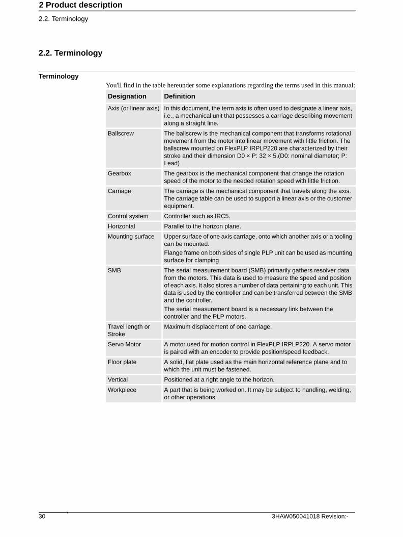
TerminologyYou'll find in the table hereunder some explanations regarding the terms used in this manual:
Designation Definition
Axis (or linear axis) In this document, the term axis is often used to designate a linear axis, i.e., a mechanical unit that possesses a carriage describing movement along a straight line.
Ballscrew The ballscrew is the mechanical component that transforms rotational movement from the motor into linear movement with little friction. The ballscrew mounted on FlexPLP IRPLP220 are characterized by their stroke and their dimension D0 × P: 32 × 5.(D0: nominal diameter; P: Lead)
Gearbox The gearbox is the mechanical component that change the rotation speed of the motor to the needed rotation speed with little friction.
Carriage The carriage is the mechanical component that travels along the axis. The carriage table can be used to support a linear axis or the customer equipment.
Control system Controller such as IRC5.
Horizontal Parallel to the horizon plane.
Mounting surface Upper surface of one axis carriage, onto which another axis or a tooling can be mounted.
Flange frame on both sides of single PLP unit can be used as mounting surface for clamping
SMB The serial measurement board (SMB) primarily gathers resolver data from the motors. This data is used to measure the speed and position of each axis. It also stores a number of data pertaining to each unit. This data is used by the controller and can be transferred between the SMB and the controller.
The serial measurement board is a necessary link between the controller and the PLP motors.
Travel length or Stroke
Maximum displacement of one carriage.
Servo Motor A motor used for motion control in FlexPLP IRPLP220. A servo motor is paired with an encoder to provide position/speed feedback.
Floor plate A solid, flat plate used as the main horizontal reference plane and to which the unit must be fastened.
Vertical Positioned at a right angle to the horizon.
Workpiece A part that is being worked on. It may be subject to handling, welding, or other operations.
3HAW050041018 Revision:- 30

2 Product description
2.3.1. Modularity
2.3 Principle structure
2.3.1. Modularity
Modularity
FlexPLP IRPLP220 is designed with high modularity what are constituted of the strokes,
driving types, axes combination, vertical axis mounting methods and cable chains directions.
FlexPLP IRPLP220 overview
Item Description Note
A Vertical axis ΝΟΤΕ:When carriage is fixed on the triangle bracket, motor is moving with the movement of vertical axis. If basement body is fixed on the interface bracket, motor is not moving.
B Second horizontal axis
C First horizontal axis The Rack and Pinion version could extend stroke to 990 mm for first horizontal axis by additional module.
D Interface bracket Used to assemble axis 3 and guide cables.
E Cable chain External cable chains are used for axes of FlexPLP IRPLP220.
F Cable box Power and resolver cable connectors are inside. Each axis has a cable box installed.
313HAW050041018 Revision:-
2 Product description
2.3.2. Axes combinations
2.3.2. Axes combinations
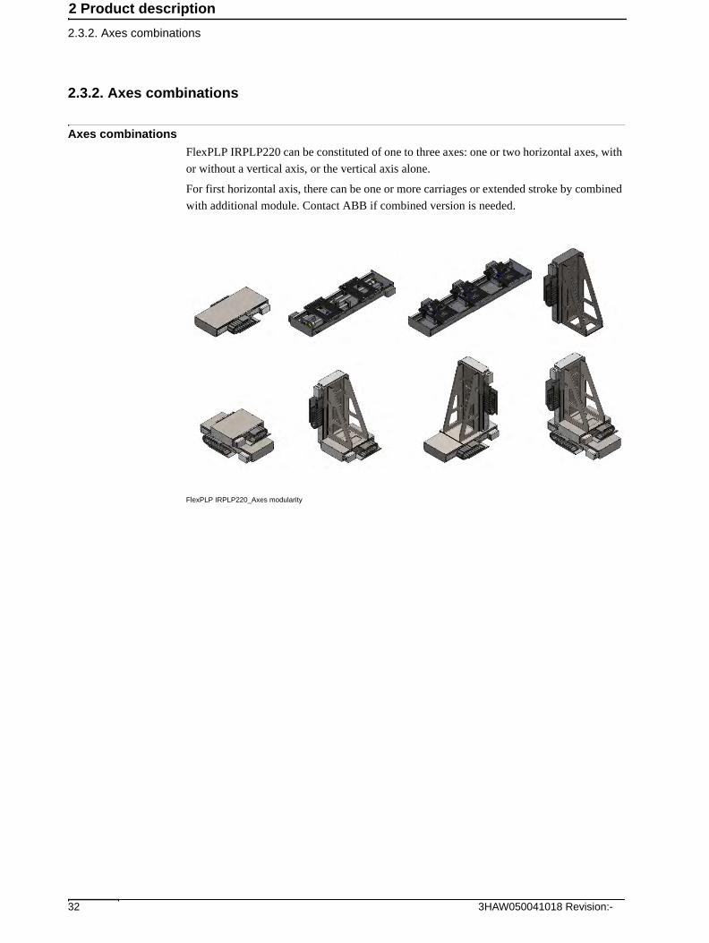
Axes combinations
FlexPLP IRPLP220 can be constituted of one to three axes: one or two horizontal axes, with
or without a vertical axis, or the vertical axis alone.
For first horizontal axis, there can be one or more carriages or extended stroke by combined
with additional module. Contact ABB if combined version is needed.
FlexPLP IRPLP220_Axes modularity
3HAW050041018 Revision:- 32

2 Product description
2.3.3. Driving types
2.3.3. Driving types
Driving types
FlexPLP IRPLP220 axes have two types of drive method: Ballscrew type and Rack and
Pinion type that have same parts except the driving system. The horizontal axes can use either
type of drive method. The vertical axis use ballscrew type. Both of the two kinds of axes are
available with stroke of 190, 270, 350, 430,510, 590 and 670.
Below table show the stokes for each axis.
FlexPLP IRPLP220_Ballscrew driving type FlexPLP IRPLP220_Rack and Pinion driving type
First Horizontal axis Second Horizontal axis Vertical axis
190 mm 190 mm 190 mm
270 mm 270 mm 270 mm
350 mm 350 mm 350 mm
430 mm 430 mm 430 mm
510 mm 510 mm 510 mm
590 mm 590 mm
670 mm
333HAW050041018 Revision:-

2 Product description
2.3.4. Vertical axis mounting and cable chain
2.3.4. Vertical axis mounting and cable chain
Vertical axis mounting and cable chain
The vertical axis of FlexPLP IRPLP220 axes has two mounting method: Body moving or
carriage moving. Both the carriage and base body of the axis can be mounted on the triangle
bracket. The dimension for two mounting method are the same at lowest position. For body
moving, there is an option of tooling flange plate for the top flange.
FlexPLP IRPLP220_Body moving FlexPLP IRPLP220_Carriage moving
The cable chain of FlexPLP IRPLP220 axes can be mounted both on left and right side. If the
connector is not moving, there is no need to assemble the cable chain. However, for second
horizontal axis and vertical axis, the mounting method of cable chain should consider the first
horizontal axis cable chain mounting method for cables routing.
FlexPLP IRPLP220_cable chain mounting
3HAW050041018 Revision:- 34

2 Product description
2.4.1. FlexPLP IRPLP220 overall specifications
2.4 Performances
2.4.1. FlexPLP IRPLP220 overall specifications
General
Below are the overall specification of FlexPLP IRPLP220.
1)Per ISO9283
Specification First Horizontal axis Second Horizontal axis Vertical axis
Stroke 190, 270, 350, 430,510, 590, or 670 mm
190, 270, 350, 430, 510, or 590 mm
190, 270, 350, 430, or 510 mm
Repeatability1) ±0.025 mm1) ±0.025 mm1) ±0.025 mm1)
Maximum speed 200 mm/s 200 mm/s 200 mm/s
Acceleration time < 0.2 s < 0.2 s < 0.2 s
Static load 220 kg 220 kg 220 kg
Dynamic load 220 kg 220 kg 220 kg
Protection index IP 54 IP 54 IP 54
353HAW050041018 Revision:-

2 Product description
2.4.2. FlexPLP IRPLP220 motor specifications
2.4.2. FlexPLP IRPLP220 motor specifications
General
The ballscrew version and Rack and Pinion version of FlexPLP IRPLP220 are using the same
servo motor.
Below are the specifications of the motor used on FlexPLP IRPLP220:
Specification Performance
Power 750 W
Nominal speed 3000 rpm
Voltage 400 V AC
Torque 2.39 Nm
Brake voltage 24 V
Brake torque 2.39 Nm
3HAW050041018 Revision:- 36
2 Product description
2.5.1. Dimensions one-axis FlexPLP IRPLP220
2.5 Dimensions
2.5.1. Dimensions one-axis FlexPLP IRPLP220
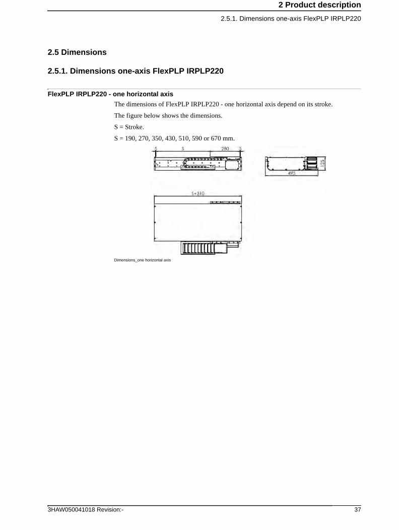
FlexPLP IRPLP220 - one horizontal axis
The dimensions of FlexPLP IRPLP220 - one horizontal axis depend on its stroke.
The figure below shows the dimensions.
S = Stroke.
S = 190, 270, 350, 430, 510, 590 or 670 mm.
Dimensions_one horizontal axis
373HAW050041018 Revision:-

2 Product description
2.5.1. Dimensions one-axis FlexPLP IRPLP220
FlexPLP IRPLP220 - one vertical axis
The dimensions of FlexPLP IRPLP220 - one vertical axis depend on its stroke.
The dimension of the vertical axis - body moving is same with vertical axis - carriage moving
when they are at low position.
The figure below shows the dimensions of one vertical axis at low position.
S = Stroke.
S = 190, 270, 350, 430 or 510 mm.
Dimensions_one vertical axis-carriage moving
Dimensions_one vertical axis-body moving
3HAW050041018 Revision:- 38

2 Product description
2.5.2. Dimensions two-axes FlexPLP IRPLP220
2.5.2. Dimensions two-axes FlexPLP IRPLP220
FlexPLP IRPLP220 - two horizontal axes
The dimensions of FlexPLP IRPLP220 unit depend on its axes strokes.
The figure below shows the dimensions of the two horizontal axes.
S1 = Stroke of the first horizontal axis. S1 = 190, 270, 350, 430, 510, 590 or 670 mm.
S2 = Stroke of the second horizontal axis. S2 = 190, 270, 350, 430, 510 or 590 mm.
Dimensions_two horizontal axes
393HAW050041018 Revision:-

2 Product description
2.5.2. Dimensions two-axes FlexPLP IRPLP220
FlexPLP IRPLP220 - one horizontal and one vertical axis
The dimensions of FlexPLP IRPLP220 unit depend on its axes strokes. The dimensions of
FlexPLP IRPLP220 unit with vertical axis - body moving is same with vertical axis - carriage
moving when they are at low position.
The figure below shows the dimensions of a two axes FlexPLP IRPLP220 with vertical axis
- carriage moving at low position with:
S1 = Stroke of the first horizontal axis. S1 = 190, 270, 350, 430, 510, 590 or 670 mm.
S3 = Stroke of the vertical axis. S3 = 190, 270, 350, 430 or 510 mm.
Dimensions_one horizontal axis and one vertical axis-carriage moving
3HAW050041018 Revision:- 40

2 Product description
2.5.2. Dimensions two-axes FlexPLP IRPLP220
The figure below shows the dimensions of a two axes FlexPLP IRPLP220 with vertical axis
- body moving at low position with:
S1 = Stroke of the first horizontal axis. S1 = 190, 270, 350, 430, 510, 590 or 670 mm.
S3 = Stroke of the vertical axis. S3 = 190, 270, 350, 430 or 510 mm.
Dimensions_one horizontal axis and one vertical axis-body moving
413HAW050041018 Revision:-

2 Product description
2.5.3. Dimensions three-axes FlexPLP IRPLP220
2.5.3. Dimensions three-axes FlexPLP IRPLP220
FlexPLP IRPLP220 three axes
The dimensions of FlexPLP IRPLP220 unit depend on its axes strokes. The dimension of a
FlexPLP IRPLP220 unit with vertical axis - body moving is same with vertical axis - carriage
moving when they are at low position.
The figure below shows the dimensions a three axes FlexPLP IRPLP220 with vertical axis -
carriage moving with:
S1 = Stroke of the first horizontal axis. S1 = 190, 270, 350, 430, 510, 590 or 670 mm.
S2 = Stroke of the second horizontal axis. S2 = 190, 270, 350, 430, 510 or 590 mm.
S3 = Stroke of the vertical axis. S3 = 190, 270, 350, 430 or 510 mm.
Dimensions_three axes
3HAW050041018 Revision:- 42

2 Product description
2.5.3. Dimensions three-axes FlexPLP IRPLP220
The figure below shows the dimensions a three axes FlexPLP IRPLP220 with vertical axis -
body moving with:
S1 = Stroke of the first horizontal axis. S1 = 190, 270, 350, 430, 510, 590 or 670 mm.
S2 = Stroke of the second horizontal axis. S2 = 190, 270, 350, 430, 510 or 590 mm.
S3 = Stroke of the vertical axis. S3 = 190, 270, 350, 430 or 510 mm.
Dimensions_three axes
433HAW050041018 Revision:-

2 Product description
2.6.1. Weight
2.6 Weight
2.6.1. Weight
Overview
The weight of the complete mechanical unit depends on the configuration. Here under are the
weight of each axis type and the total weight of each available combination of axis:
Axis type Stroke (mm) Weight (kg)
Ballscrew 190 67
Ballscrew 270 72
Ballscrew 350 78
Ballscrew 430 84
Ballscrew 510 89
Ballscrew 590 95
Ballscrew 670 99
Rack and Pinion 190 65
Rack and Pinion 270 70
Rack and Pinion 350 75
Rack and Pinion 430 81
Rack and Pinion 510 86
Rack and Pinion 590 91
Rack and Pinion 670 97
Interface bracket 190 33
Interface bracket 270 37
Interface bracket 350 39
Interface bracket 430 43
Interface bracket 510 46
3HAW050041018 Revision:- 44
3 Unpacking and handling
3.1. Pre-requisites for reception
3 Unpacking and handling
3.1. Pre-requisites for reception
Pre-requisites
The check-list below details what must be observed before proceeding with the unpacking
and/or installation of the FlexPLP:
Action Note
1. Make sure that only qualified installation personnel conforming to all national and local codes are allowed to perform the installation.
2. Make sure that FlexPLP has not been damaged, by visual inspection.
Specified in Unpacking and acceptance on page 46.
3. Make sure that the lifting device to be used is dimensioned to handle the weight of FlexPLP.
Specified in Weight on page 44
4. When these prerequisites have been met, FlexPLP may be taken to its storage or installation site.
453HAW050041018 Revision:-
3 Unpacking and handling
3.2. Unpacking and acceptance
3.2. Unpacking and acceptance
TIP!
Before unpacking the unit, quickly check that the package is not damaged, and that the goods
are as ordered.
Contents
The content of the delivery package should be detailed on the delivery note.
A standard delivery package generally contains (not including options):
• FlexPLP
• The SMB box(es) and the cables
Inspection
FlexPLP is wrapped in a protective bag. Unpack it and check for any visible transport
damage. If FlexPLP is damaged, stop unpacking and contact ABB.
Make sure that all parts of the packing list have been delivered.
Cleaning
If the unit seems to have been contaminated by impurities during the transport, clean them
with a clean lint-free cloth.
3HAW050041018 Revision:- 46

3 Unpacking and handling
3.2. Unpacking and acceptance
Identification plate
To identify the delivery, read the identification plates and compare them to the delivery note.
There is one identification plate per axis, which displays the axis assembly drawing number,
the serial number, and the weight.
The serial number is an alpha-numerical combination of the following types:
IRPLP220X0000 - 00 for the first horizontal axes, IRPLP220Y0000 - 00 for the second
horizontal axes, and IRPLP220Z0000 - 00 for the vertical axis.
When FlexPLP IRPLP220 has more than one axis, the digits are identical on all plates.
The plates can be found on the sides of FlexPLP IRPLP220:
ID plate location
473HAW050041018 Revision:-

3 Unpacking and handling
3.3. Handling/lifting
3.3. Handling/lifting
Safety
CAUTION!
Before lifting FlexPLP, read through the safety instructions carefully.
Handling equipment for FlexPLP
CAUTION!
Only use straps for lifting FlexPLP. Chains could damage FlexPLP.
Lifting the FlexPLP
Use lifting straps to lift FlexPLP with vertical axis by lifting the interface bracket.
Tighten the eye bolts (A) to the unit as shown on the following picture:
Lift of FlexPLP IRPLP220
For the dimensions and lifting weight, please refer to Dimensions on page 37 and Weight on
page 44.
NOTE!
Before lifting FlexPLP IRPLP220, the carriages of the horizontal axis must be at mid-stroke
and the vertical axis must be in low position.
Lifting the Interface bracket
Use lifting straps to lift the interface bracket.
No. Equipment for horizontal axis Equipment for vertical axis
1 4 Eye-bolts with M8 thread hole 2 Eye-bolts with M8 thread
2 M8 x 25 screw M8 nuts
3 Lifting straps rated for a minimum of 400kg
Lifting straps rated for a minimum of 400kg
3HAW050041018 Revision:- 48
4 Installation and commissioning
4.1. Introduction
4 Installation and commissioning
4.1. Introduction
Safety information
Before any service work is commenced, it is important that all safety information is observed!
Read Safety on page 11 before performing any service work.
Required equipment
Bolts and screws and tightening torques
Specified in Bolt, screws, tightening torques on page 97.
Equipment Note
Handling equipment Specified in Handling/lifting on page 48.
Standard toolkit Specified in Standard toolkit on page 98.
Other tools and procedures may be required. See references to these procedures in the step-by-step instructions below.
Specified in Special tools on page 99.
493HAW050041018 Revision:-

4 Installation and commissioning
4.2.1. Introduction
4.2 Mechanical installation
4.2.1. Introduction
Overview
The FlexPLP IRPLP220 is mounted on a floor plate, a tooling frame or another FlexPLP
IRPLP220. The below picture shown the mounting surfaces.
Mounting surfaces
NOTE!
FlexPLP IRPLP220 must be mounted on a machined leveling mounting surface.
Carefully check the work area of FlexPLP IRPLP220 before setting the system into service.
Make sure that the area is free of all personnel when the unit moves. Also check that no object
is located on the cover plates of FlexPLP IRPLP220.
WARNING!
Cables and pipes must not be contact with moving parts.
Inclination
The mounting surface must be horizontal. If FlexPLP IRPLP220 is mounted on a base plate,
the base plate would be mounted horizontally on the ground.
Item Name Description
A Basement body The basement body would be installed on a floor plate, a tooling frame or another FlexPLP IRPLP220.
B Mounting surface of FlexPLP IRPLP220 carriage
Tools, fixtures or another FlexPLP IRPLP220 axis can be mounted on it.
3HAW050041018 Revision:- 50

4 Installation and commissioning
4.2.2. Mounting surface (fastening of the FlexPLP IRPLP220 to the floor plate)
4.2.2. Mounting surface (fastening of the FlexPLP IRPLP220 to the floor plate)
Robustness
The FlexPLP IRPLP220 must be secured on a mounting surface that be sized to withstand the
static loads resulting from the weight of the equipment and the dynamic loads generated by
the movements of the carriages and the weight carried.
The table below gives the resulting static loads generated by a FlexPLP IRPLP220 at nominal
payload:
Holes Configuration
The figures below show the countersunk and dowel holes prepared in the base body of the
horizontal axis.The unit must be secured with socket head hex screws M8 and two 8 mm
dowel pins.
The table below gives the detail numbers of holes and dimensions depending on the strokes.
Holes configuration_floor plate mounting
X axis Y axis Z axis
Load 600 kg 500 kg 400 kg
Stroke
(mm)
Body length
L0 (mm)
Pin holes
distance L (mm)
Number of
countersunk holes
N × M
(No.× mm)
190 480 240 8 1 x 80
270 560 320 8 1 x 80
350 640 320 8 1 x 160
430 720 400 8 1 x 160
510 800 480 8 1 x 160
590 880 560 8 1 x 160
670 960 640 12 2 x 160
513HAW050041018 Revision:-

4 Installation and commissioning
4.2.2. Mounting surface (fastening of the FlexPLP IRPLP220 to the floor plate)
Floor Plate
The FlexPLP IRPLP220 must be secured on a floor plate or a tooling frame. ABB provide the
option of standard floor plate. With the standard floor plate, it is convenient for replacement
of a whole FlexPLP IRPLP220 unit. Contact ABB if a floor plate is needed.
FlexPLP IRPLP220_floor plate option
The figures below show the dimensions of the floor plate.
The table below gives the detail numbers of holes and dimensions depending on the strokes
Dimensions _floor plate
Stroke
(mm)
Length
L0 (mm)
Length
L (mm)
Length
L1 (mm)
Length
L2 (mm)
No. of
Ø20 holes
N × M
(No. × mm)
190 470 240 200 0 6 1 x 80
270 550 320 240 0 6 1 x 80
350 630 320 280 0 6 1 x 160
430 710 400 200 240 8 1 x 160
510 790 480 240 240 8 1 x 160
590 870 560 280 240 8 1 x 160
670 950 640 280 320 8 2 x 160
3HAW050041018 Revision:- 52

4 Installation and commissioning
4.2.3. Mounting surfaces (fastening of an axis or customer equipment)
4.2.3. Mounting surfaces (fastening of an axis or customer equipment)
Mounting surfaces
For all axes have the same structure, the mounting surface of the horizontal and vertical axis
carriages are the same. It includes eight Ø9 through holes and four Ø8H7 through holes for
the fastening of another axis or the customer equipment.
Mounting surface of axis carriage
For vertical axis, the mounting surface for customer equipment has another option where the
payload is mounted on the flange. The flange includes an area where the holes could be drilled
according to the requirements.
Mounting surface of axis flange
533HAW050041018 Revision:-

4 Installation and commissioning
4.2.4. Jogging axes of a unit with FlexPendant
4.2.4. Jogging axes of a unit with FlexPendant
Jogging properties
To jog is to manually position or move axes using the FlexPendant. It is possible to jog the
axes under the following conditions:
• The system has been started.
• No programmed operation is running.
• The system is in Manual mode.
• The enabling device is pressed and the system is in Motors On state.
Any changes you make to jogging properties only affects the currently selected mechanical
unit. All jogging properties are saved and restored when you return to jog that mechanical
unit.
For details, please refer to Operating manual - IRC5 with FlexPendant.
Select mechanical unit
If the system has more than one unit or additional axes, then it is needed to select which
mechanical unit to jog when using the joystick. Each mechanical unit that can be jogged is
represented in the mechanical units list. The name of the unit is defined in the system
configuration. Each unit also has a symbol that is used in the Status bar.
There are three ways to select mechanical unit.
• Using the Quickset menu Mechanical unit.
On the Quickset menu, tap Mechanical unit, then tap to select a mechanical unit.
Select unit_Quickset menu
3HAW050041018 Revision:- 54

4 Installation and commissioning
4.2.4. Jogging axes of a unit with FlexPendant
• Using the Select mechanical unit button.
Press the Select mechanical unit button to change unit. One press on the button changes to the
next mechanical unit, as steps in a cycle.
Select unit_hard button
• Using the Jogging window on the ABB menu.
One the ABB menu, tap Jogging. Then tap Mechanical unit. Tap the mechanical unit to be
jogged, and then tap OK.
The selected mechanical unit is active until you select another unit, even if you close the
Jogging window.
Select unit_Jogging window
Jog axis by axis
Jog the linear axis by Joystick, notice the Joystick Directions.
The Joystick Directions area shows how joystick axes correspond to the selected coordinate
system’s axes. The all axes of PLP can be jogged manually using the joystick. Please check
your plant or product documentation to determine the movement patterns for each axis.
Joy axix_Joystick
A Mechanical unit menu button
B Mechanical unit, a selected unit is highlighted
553HAW050041018 Revision:-
Continues on next page

4 Installation and commissioning
4.2.4. Jogging axes of a unit with FlexPendant
Incremental movement for precise positioning
Use incremental movement to jog the unit in small steps, which enables very precise
positioning.
This means that each time the joystick is deflected, the device moves one step (increment). If
the joystick is deflected for one or more seconds, a sequence of steps, (at a rate of 10 steps
per second), will be performed as long as the joystick is deflected.
Default mode is no increment, then the robot moves continuously when the joystick is
deflected.
There are three ways to select the increment size.
• Using the Quickset menu increments.
On the Quickset menu, tap Mechanical unit, then tap to select a mechanical unit.
Increments set_Quickset menu
• Using the Toggle increments button.
Press the Toggle increments button to switch increment size, toggle between no increments
and the increment size you previously selected in the Jogging window.
Increments set_hard button
• Using the Jogging window on the ABB menu.
One the ABB menu, tap Jogging. Then tap incrment. Tap the desired increment mode, and
then tap OK.
Increments set_Jogging window
Choose between small, medium or large increments. You can also define your own increment
movement sizes.
3HAW050041018 Revision:- 56

4 Installation and commissioning
4.2.5. Fastening a unit to the floor plate
4.2.5. Fastening a unit to the floor plate
Equipment
The required equipment is the standard toolkit, and in particular:
Procedure
1. Hex keys (Allen keys) 3 and 6 (socket wrenches recommended)
2. Torque wrench used with socket head cap 6 mm. See Bolt, screws, tightening torques on page 97
3. Two dowel pins Ø8 and eight M8 socket head screws for 190-590 stroke unit (twelve eight M8 socket head screws for 670 mm stroke unit).
Steps Actions Info/Illustration
1. As it is necessary to jog the first horizontal axis carriage to tighten all the screws, you must prepare the equipment (controller, cables, SMB box) necessary to control the unit. See Jogging axes of a unit with FlexPendant on page 54 and Cabling on page 14.
2. Dismantle the cover plate (B) of the first horizontal axis by dismantling its six M5x10 Class 8.8 fixing screws (A).
Dismantle axis one cover plate
573HAW050041018 Revision:-

4 Installation and commissioning
4.2.5. Fastening a unit to the floor plate
3. Remove the cover plate by sliding it from one end of FlexPLP IRPLP220.
Remove the cover plate
4. Lift FlexPLP IRPLP220 and position it on the mounting surface.
Position on the floor plate
5. Connect the power and resolver cables to the unit. If needed, use the controller’s FlexPendant to move the first horizontal axis carriage and clear the access to the countersunk holes and pin holes of the base body.
Steps Actions Info/Illustration
3HAW050041018 Revision:- 58

4 Installation and commissioning
4.2.5. Fastening a unit to the floor plate
6. Fix the first horizontal axis of FlexPLP IRPLP220 by fixing the following fastening parts on the basement body: the two dowel pins Ø8 mm (A) and eight M8 screws with lock washer (B).
Body fixed on floor plate
7. Put the first horizontal axis cover back in position.
Steps Actions Info/Illustration
593HAW050041018 Revision:-

4 Installation and commissioning
4.3.1. Connectors and internal equipment wiring
4.3 Cabling and control
4.3.1. Connectors and internal equipment wiring
Connectors
Each axis of FlexPLP IRPLP220 has its own cable box which containing the power cable
connector and the resolver cable connector.
External harness
FlexPLP IRPLP220 integrates an external harness of one power cable and one resolver cable
for the control of customer equipment.
Read Safety on page 11before performing any service work.
Quantity Specification
1 Power cable, with M16 connector
1 resolver cable, With M16 connector
3HAW050041018 Revision:- 60

4 Installation and commissioning
4.3.2. Control architecture
4.3.2. Control architecture
Overview
FlexPLP IRPLP220 is driven by the IRC5 through a set of cables and a SMB box.
The standard control system includes:
• Controller: IRC5 (A). An IRC5 controller can control up to 36 axis, in up to 6 motion
tasks. See Controller capabilities on page 62.
• Floor resolver cable, IRC5 to SMB (B). For IRC5’s XS.2 (single cabinet’s SMB
connection), A4.XS2 (drive module’s SMB connection), XS.41 (single cabinet’s
external axis SMB connection), or A4.XS41 (drive module’s external axis SMB
connection).
• Floor power cable, IRC5 to SMB (C). Exists in 2 types:
- 6 axis type for IRC5’s XS.1 (single cabinet’s robot power connection) or A4.X1
(drive module’s robot power connection)
- 3 axis type for XS.7 (single cabinet’s external axis power connection) or A4.X7
(drive module’s external axis power connection).
• SMB Box (D). Exists in 3 types: 1, 3, or 6 axes. Equipped with brake release trigger
and back-up battery.
• FlexPLP IRPLP220 resolver cable, SMB to PLP (E) For 1 axis
• FlexPLP IRPLP220 power cable, SMB to PLP (F) For 1 axis
Each type of cable is available in a length of 2, 5, 10 or 15m.
FlexPLP IRPLP220 cables
Item Description
A IRC5
B Floor resolver cable
C Floor power cable
D SMB Box
E FlexPLP IRPLP220 resolver cable
F FlexPLP IRPLP220 power cable
613HAW050041018 Revision:-

4 Installation and commissioning
4.3.3. Controller capabilities
4.3.3. Controller capabilities
General
Depending on its configuration, an IRC5 controller with one drive module can control up to
nine axes: six axis controlled by the Main Drive Unit (MDU) and up to three axis controlled
by the Additional Drive Units (ADU). Up to three additional drive modules can be added to
the controller. For a total of four drive modules, up to thirty-six axes can be driven by an IRC5
controller. Read 3HAC021313 - Product Manual, IRC5 Controller.
Furthermore, a controller with Multi-move system can manage up to six motions tasks,
regardless of the number of drive modules. This means that if the system configuration has
more than six FlexPLP IRPLP220, two or more units must be grouped in one motion task.
Read 3HA021395 - Additional axes and stand alone controller.
NOTE!
On one drive module, the axes of one FlexPLP IRPLP220 unit shouldn't be controlled across
the MDU (six first drive units) and the ADU (up to three drive units). For example, a 3 axis
FlexPLP IRPLP220 should not have two axes controlled by the MDU and one axis controlled
by one of the ADU.
Configurations: fully occupied drive module
Below are all the configurations in which all of the axes of one drive module are occupied:
# Main Drive Unit Additional Drive Units PLP
Drive 1 Drive 2 Drive 3 Drive 4 Drive 5 Drive 6 Drive 7 Drive 8 Drive 9
1 PLP3 axis PLP3 axis PLP3 axis 3
2 PLP3 axis PLP3 axis PLP2 axis PLP1 axis
4
3 PLP3 axis PLP3 axis PLP1 axis
PLP1 axis
PLP1 axis
5
4 PLP3 axis PLP2 axis PLP1 axis
PLP3 axis 4
5 PLP3 axis PLP2 axis PLP1 axis
PLP2 axis PLP1 axis
5
6 PLP3 axis PLP2 axis PLP1 axis
PLP1 axis
PLP1 axis
PLP1 axis
6
7 PLP3 axis PLP1 axis
PLP1 axis
PLP1 axis
PLP3 axis 5
8 PLP3 axis PLP1 axis
PLP1 axis
PLP1 axis
PLP2 axis PLP1 axis
6
9 PLP3 axis PLP1 axis
PLP1 axis
PLP1 axis
PLP1 axis
PLP1 axis
PLP1 axis
71)
10 PLP2 axis PLP2 axis PLP2 axis PLP3 axis 4
11 PLP2 axis PLP2 axis PLP2 axis PLP2 axis PLP1 axis
5
12 PLP2 axis PLP2 axis PLP2 axis PLP1 axis
PLP1 axis
PLP1 axis
6
13 PLP2 axis PLP2 axis PLP1 axis
PLP1 axis
PLP3 axis 5
3HAW050041018 Revision:- 62

4 Installation and commissioning
4.3.3. Controller capabilities
1)Configuration in which two or more mechanical units must be grouped in one motion task.
14 PLP2 axis PLP2 axis PLP1 axis
PLP1 axis
PLP2 axis PLP1 axis
6
15 PLP2 axis PLP2 axis PLP1 axis
PLP1 axis
PLP1 axis
PLP1 axis
PLP1 axis
71)
16 PLP2 axis PLP1 axis
PLP1 axis
PLP1 axis
PLP1 axis
PLP3 axis 6
17 PLP2 axis PLP1 axis
PLP1 axis
PLP1 axis
PLP1 axis
PLP2 axis PLP1 axis
71)
18 PLP2 axis PLP1 axis
PLP1 axis
PLP1 axis
PLP1 axis
PLP1 axis
PLP1 axis
PLP1 axis
81)
19 PLP1 axis
PLP1 axis
PLP1 axis
PLP1 axis
PLP1 axis
PLP1 axis
PLP3 axis 71)
20 PLP1 axis
PLP1 axis
PLP1 axis
PLP1 axis
PLP1 axis
PLP1 axis
PLP2 axis PLP1 axis
81)
21 PLP1 axis
PLP1 axis
PLP1 axis
PLP1 axis
PLP1 axis
PLP1 axis
PLP1 axis
PLP1 axis
PLP1 axis
91)
633HAW050041018 Revision:-

4 Installation and commissioning
4.3.4. Examples of configurations
4.3.4. Examples of configurations
System example: One 3 axis FlexPLP IRPLP220
Below is an example of configuration with one single cabinet IRC5 which controls one 3 axis
FlexPLP IRPLP220 through one 3 axis SMB box. Note that if the controller’s XS.1 and XS.2
are already occupied, and if the number of drive units in the controller is enough for all the
mechanical units, it is possible to use a power cable for IRC5’s XS.7 (3 axis) and a resolver
cable for XS.41.
One 3 axes FlexPLP IRPLP220
System example: Two 3 axis FlexPLP IRPLP220
Below is an example of configuration with one single cabinet IRC5 which controls two 3 axis
FlexPLP IRPLP220 through one 6 axis SMB box.
Two 3 axes FlexPLP IRPLP220
3HAW050041018 Revision:- 64

4 Installation and commissioning
4.3.4. Examples of configurations
System example: Two 3 axis FlexPLP IRPLP220 and three 1 axis FlexPLP IRPLP220
Below is an example of configuration with one single cabinet IRC5 (with nine drive units)
which controls two 3 axis FlexPLP IRPLP220 and three 1 axis FlexPLP IRPLP220 through
respectively one 6 axis SMB box and one 3 axis SMB box.
Two 3axes FlexPLP IRPLP220 and three 1 axis FlexPLP IRPLP220
653HAW050041018 Revision:-

4 Installation and commissioning
4.3.4. Examples of configurations
System example: Four 3 axis FlexPLP IRPLP220
Below is an example of configuration with one IRC5 (with six drive units) equipped with one
additional drive module (also with six drive units), connected with one Ethernet cable and one
safety cable. The IRC5 controls four 3 axis FlexPLP IRPLP220 through two 6 axis SMB box.
Four 3 axes FlexPLP IRPLP220
3HAW050041018 Revision:- 66

4 Installation and commissioning
4.3.4. Examples of configurations
System example: Six 3 axis FlexPLP IRPLP220
Below is an example of configuration with one IRC5 (with nine drive units) equipped with
one additional drive module (also with nine drive units). The IRC5 controls six 3 axis
FlexPLP IRPLP220 through two 6 axis SMB box, and two 3 axis SMB box.
Six 3 axes FlexPLP IRPLP220
673HAW050041018 Revision:-

4 Installation and commissioning
4.3.4. Examples of configurations
System example: Eight 3 axis FlexPLP IRPLP220
Below is an example of configuration with one IRC5 (with nine drive units) equipped with
two additional drive module (one with nine drive units and the other one with six drive units),
connected with two Ethernet cables and two safety cables. The IRC5 controls eight 3 axis
FlexPLP IRPLP220 through three 6 axis SMB box, and two 3 axis SMB box. Since the
system has eight FlexPLP IRPLP220, three mechanical units or more are grouped in two
motion tasks or more.
Eight 3 axes FlexPLP IRPLP220
3HAW050041018 Revision:- 68

4 Installation and commissioning
4.3.4. Examples of configurations
System example: Four 3 axis FlexPLP IRPLP220, one 2 axis FlexPLP IRPLP220, and two 1 axis FlexPLP IRPLP220
Below is an example of configuration with one IRC5 (with nine drive units) equipped with
one additional drive module (with seven drive units). The IRC5 controls four 3 axis FlexPLP
IRPLP220, one 2 axis FlexPLP IRPLP220, and two 1 axis FlexPLP IRPLP220 through two
6 axis SMB box, one 3 axis SMB box, and one 1 axis SMB box. Since the system has seven
FlexPLP IRPLP220, two mechanical units or more are grouped in one motion task or more.
Four 3 axes FlexPLP IRPLP220 one 1 axes FlexPLP IRPLP220 one 2 axis FlexPLP IRPLP220
693HAW050041018 Revision:-

4 Installation and commissioning
4.3.5. Configuration files
4.3.5. Configuration files
Overview
In order for the controller to identify that the FlexPLP exists and to control it, configuration
files must be loaded into the IRC5 system.
Two files need to be set:
• The Motion Control file: MOC.cfg
• The System file: SYS.cfg
The Motion control file is provided with the product.
The system file should be set depending on your existing system and the layout.
Detailed instructions regarding the setting and loading of these files can be found in the
following controller documentation:
• 3HAC021313-001 - Product manual, IRC5 Robot Controller
• 3HAC035738-001 - Product Manual, IRC5 Compact
• 3HAC16590-1 - Operating manual, IRC5 with FlexPendant
Once the parameters are properly set in the system, calibrate the unit(s) as described in
Calibration on page 71.
3HAW050041018 Revision:- 70
Continues on next page

5 Calibration
5.1. Introduction / When to calibrate
5 Calibration
5.1. Introduction / When to calibrate
General
This chapter includes general information and detailed procedures about the calibration
methods: The fine calibration and the update of the revolution counters.
When to perform a fine calibration
The fine calibration of the FlexPLP must be done at the first commissioning or after the
replacement of mechanical parts such as:
• Servomotor
• driving belt/pulley or gear/rack
• Ballscrew
• Replacement of a complete axis
For FlexPLP IRPLP220 without calibration index system, an Ø8 x 100 mm pin is required to
perform the fine calibration.
For FlexPLP IRPLP220 with calibration index system, an Ø8 x 50 mm pin is required to
perform the fine calibration.
When to update the revolution counters
The FlexPLP axis must be calibrated each time the contents of the revolution counter are
changed or lost. This will occur when:
• The battery is discharged
• A resolver error occurs
• The signal between a resolver and measurement board is interrupted (for example:
cable disconnected)
• A FlexPLP axis is moved with the control system disconnected
The revolution counters must also be updated after the device and controller are connected at
the first installation.
Power failure
There's no need to calibrate the FlexPLP after a power failure, the backup battery included in
the SMB box will store the resolver position until power is restored.
Precautions
CAUTION!
• If an axis is incorrectly calibrated or if the revolution counter is incorrectly updated, it
will cause incorrect positioning, which in turn may cause damage or injury! Check the
calibration position very carefully after each update.
• Before any service work, make sure that nobody stands near the mechanical unit when
the carriage moves, and make sure that no object which could get in the way of the
carriage or jam between the carriage and the covers.
713HAW050041018 Revision:-

5 Calibration
5.2. Calibration points
5.2. Calibration points
Calibration point, without calibration index system
For the FlexPLP IRPLP220 without calibration index system, there is only one calibration
hole on the basement body. And the carriage has a corresponding calibration hole. The
calibration point is reached when the two calibration holes align exactly with each other. An
Ø8 x 100 pin should be used to do the fine calibration.
Calibration holes on basement and carriage
NOTE!
As FlexPLP IRPLP220 without calibration index system has flexible installation methods for
both parts and axes combination, there are only one calibration point for each axis.
Here are the location of the calibration holes on the side plate of FlexPLP IRPLP220
basement.
Calibration holes per axis
A One calibration hole on the side plate of the basement.
NOTE: To make the calibration hole on the carriage visible, here the side plate of the basement is made semi-transparent.
B Calibration hole on the carriage
C Calibration pin
3HAW050041018 Revision:- 72

5 Calibration
5.2. Calibration points
Calibration point, with calibration index system
For the FlexPLP IRPLP220 with calibration index system, the calibration index system was
installed on one side of the carriage. And there is a corresponding calibration hole on the
basement body side. The calibration point is reached when the two calibration holes align
exactly with each other. An Ø8 x 50 pin should be used to do the fine calibration.
Calibration holes on basement and index system
NOTE!
As FlexPLP IRPLP220 with calibration index system has flexible installation methods for
both parts and axes combination, there are only one calibration index system for each axis.
Here are the location of the calibration holes on the index system of FlexPLP IRPLP220.
Calibration index system per axis
A Calibration mark on the side plate of the basement.
B Calibration index system
C Calibration hole on the index system.
NOTE: To make the calibration hole on the basement body visible, here the calibration index system is made semi-transparent.
D Calibration pin
E Calibration hole on basement
733HAW050041018 Revision:-

5 Calibration
5.3. Fine calibration
5.3. Fine calibration
Calibration Pin, without calibration index system
The fine calibration of the FlexPLP without calibration index system must be done with an
Ø8 x 100 mm calibration pin.
TIP!
You can order a calibration pin from ABB under the reference number 3HAW050041927. See
Special tools on page 99
Calibration Pin, with calibration system
The fine calibration of the FlexPLP with calibration index system must be done with an Ø8
x 50 mm calibration pin.
TIP!
You can order a calibration pin from ABB under the reference number 3HAW050041930. See
Special tools on page 99
Procedure
Steps Action Info/Illustration
1. Using the FlexPendant, jog the carriage or calibration index system close to the calibration point. See Jogging axes of a unit with FlexPendant on page 54.
2. Jog the axis slowly until the two calibration holes are aligned Insert the calibration pin.
Fine calibration_without index system
Fine calibration_with index system
3HAW050041018 Revision:- 74

5 Calibration
5.3. Fine calibration
3. On the FlexPendant, tap on the ABB logo to access the ABB menu and tap on Calibration.
All mechanical units connected to the system are shown along with their calibration status.
4. Tap to select the mechanical unit and then tap to select Calib.Parameters.Tap Fine Calibration..., a dialog box is displayed prompting to performing the actual calibra-tion. A warning that updating the revolution counters can change. Programmed FlexPLP IRPLP220 positions are also displayed. Tap Yes to proceed.
Steps Action Info/Illustration
753HAW050041018 Revision:-

5 Calibration
5.3. Fine calibration
5. Select the check-box for the axis to calibrate.
6. Tap Calibrate. A dialog box is displayed, warning that calibration of the selected axes will be changed, which cannot be undone:
Tap Calibrate to proceed. Then a dialog box announcing that the calibration process has started would display.
To cancel the calibration, tap Cancel
7. The axis is calibrated and the system returns to the list of available mechanical units.
ny
ny
Steps Action Info/Illustration
3HAW050041018 Revision:- 76
Continues on next page

5 Calibration
5.4. Update of the revolution counters
5.4. Update of the revolution counters
Procedure
Steps Action Info/Illustration
1. Using the FlexPendant, jog the carriage or calibration index system to the calibration point. See Jogging axes of a unit with FlexPendant on page 54 .
calibration position_without index system
calibration position_with index system
2. On the FlexPendant, tap on the ABB logo to access the ABB menu and tap Calibration.
All mechanical units connected to the system are shown along with their calibration status.
y
773HAW050041018 Revision:-

5 Calibration
5.4. Update of the revolution counters
3. Tap to select the mechanical unit and then tap to select Rev.Counters. Tap Update Revolution counters..., a dialog box will display warning that updating the revolution counters may change programmed FlexPLP positions. Tap Yes to display the axis selection window.
4. Select the axis to have its revolution counter updated by ticking in the box to its left. Or tapping Select all to and then tapping Update to update revolution counters for all axes.
Steps Action Info/Illustration
3HAW050041018 Revision:- 78

5 Calibration
5.4. Update of the revolution counters
5. Tap Update. A dialog box is displayed, warning that calibration of the selected axes will be changed, which cannot be undone.
Tap Calibrate to proceed.
Tap Cancel to cancel.
6. Tap Update to update the selected revolution counters and removes the tick from the list of axes.
Steps Action Info/Illustration
793HAW050041018 Revision:-

5 Calibration
5.4. Update of the revolution counters
3HAW050041018 Revision:- 80

6 Maintenance
6.1. Introduction
6 Maintenance
6.1. Introduction
General
This chapter details all maintenance activities recommended for the FlexPLP.
It is based on the maintenance schedule, located in the beginning of the chapter. The schedule
contains information about required maintenance activities including intervals and refers to
procedures for the activities. Each procedure contains all information required to perform the
activity, for example: required tools and materials. The procedures are gathered in different
sections, divided according to the maintenance activity.
Safety information
Observe all safety information before conducting any service work!
There are general safety aspects that must be read through, as well as more specific safety
information that describe danger and safety risks when performing the procedures. Read
Safety on page 11 before performing any service work.
Precautions
The precautions below should be observed before proceeding with the maintenance of the
FlexPLP.
CAUTION!
• Before any intervention on the mechanical and electrical components, all power
supplies to the FlexPLP as well as to other machines within the danger zone must be
turned off.
• If required, the main switch should be locked.
• Make sure that the pneumatic system is not pressurized.
• Use only original ABB spare parts. The use of unauthorized parts or others than
original parts will void the warranty.
Required equipment
Bolts and screws and tightening torques
Specified in Bolt, screws, tightening torques on page 97.
Equipment Note
Handling equipment Specified in Handling/lifting on page 48.
Standard toolkit Specified in Standard toolkit on page 98.
Other tools and procedures may be required. See references to these procedures in the step-by-step instructions below.
Specified in Special tools on page 99.
813HAW050041018 Revision:-

6 Maintenance
6.1. Introduction
Maintenance position
Before proceeding any service work, FlexPLP IRPLP220 must be in its maintenance
position: horizontal axes carriages on their mid-stroke and vertical axis carriage in low
position.
The mounting method of the vertical axis showing below is carriage plate fixed with the
triangle bracket.
Maintenance position
3HAW050041018 Revision:- 82

6 Maintenance
6.2. Maintenance planning
6.2. Maintenance planning
The FlexPLP IRPLP220 must be maintained regularly to ensure proper function. The
maintenance activities and intervals are described in the table below.
Non-predictable situations also give rise to inspections of the product. Any damages must be
attended to immediately!
The inspection intervals do not specify the life of each component.
NOTE!
Battery low alert (38213 Battery charge low) is displayed when remaining backup capacity
(robot powered off) is less than two months. Typical lifetime of a new battery is 36 months if
the robot is powered off 2 days/week or 18 months if the robot is powered off 16 h/day. The
lifetime can be extended (approx. 3 times) for longer production breaks by a battery shutdown
service routine. See Operating manual - IRC5 with FlexPendant for instructions.
Item Maintenance Interval More info.
General condition
Covers removed, inspect the condition of the unit and clean it thoroughly.
1 month Inspection on page 84.
Cables and connectors
Look for wearing or damages. 1 month
cable chains Look for wearing or damages. 1 month
Linear guide ways and ball bearings blocks
Inspect, clean, and lubricate 3 month or every 100 km
Lubrication on page 85.
Ballscrew Inspect, clean, and lubricate 3 month or every 100 km
Driving belt • Look for premature wearing.
• Measure the belt tension and adjust it if necessary.
• Replace the belt in case of apparent damage.
1 year Driving belt (tension check, adjustment and replacement) on page 87.
Pinion and rack and gearbox
Inspect, clean, temperature and lubricate.
3 month or every 100 km
SMB box back-up battery
Replace the battery Battery low alert (1)
SMB Battery pack replacement on page 91.
833HAW050041018 Revision:-

6 Maintenance
6.3. Inspection
6.3. Inspection
General
A thorough inspection of the FlexPLP IRPLP220 should be done at least once a year.
All covers removed, clean the unit with a lint free cloth.
CAUTION!
Before any intervention on the mechanical and electrical components, all power supplies to
FlexPLP IRPLP220 as well as to other machines within the danger zone must be turned off.
Remember to go first through the inspections that require the system to be live (for example:
test of all electrical functions and search for abnormal noise).
Emergency stop
To check the emergency stop function, the unit must be stationary. Press the emergency stop
button and perform the procedure for restart after an emergency stop as detailed in the
controller documentation.
Electrical functions
Test all the electrical functions.
Make sure that each carriage can reach the limits of its stroke.
Abnormal noise
Look for any abnormal noise, for example: bearing noise.
Cables
Inspect all cables. If a cable is damaged due to wear or pinching, replace it. If a cable rubs
against sharp edges, extend the cable so that it hangs freely.
Contacts
Make sure that all plugs are properly connected and that there is no clearance.
Cable chain
Check the condition of the cable chain and in particular the state of the mechanical links and
the fastening points (carriage and base plate).
3HAW050041018 Revision:- 84

6 Maintenance
6.4. Lubrication
6.4. Lubrication
General
For ballscrew type of FlexPLP IRPLP220, each axis of FlexPLP IRPLP220 has 5 lubrication
points: On the four ball bearings block, and on the ballscrew nut.
For gear and rack type of FlexPLP IRPLP220, each axis of FlexPLP IRPLP220 has 4
lubrication points on the four ball bearings block and rack need lubrication.
WARNING!
Use lithium soap grease, class NLGI 0, with a mineral oil base, doped with EP (extreme
pressure) additives. The base oil viscosity must be ISO VG68 to ISO VG 100.Grease doped
with EP additives is absolutely necessary, due to high loads on blocks.
Lubrication ports of ballscrew type
To access the lubrication ports of the horizontal axis, make sure that the carriage is in
maintenance position (mid-stroke) and remove the upper and side covers.
If necessary, clean the ballscrew and/or the linear guides with a lint-free cloth and slightly
lubricate them with a brush.
Use a manual pump to inject grease in the five nipples. If difficult to reach the nut grease
nipple for small strokes, try to move the carriage to the end. If necessary, remove the flange
frame.
Lubrication ports_ ballscrew type
Equipment Note
Lubricant CASTROL Longtime PD0
Lubricant KLÜBER Microlube GB0
Lubricant TOTAL Multis EP 0
Port 1,2,3,4
Ball bearing blocks
Ports 5 Nut of the ballscrew
853HAW050041018 Revision:-

6 Maintenance
6.4. Lubrication
Lubricate ports of gear and rack type
Lubrication ports_gear and rack type
Port 1,2,3,4
Ball bearing blocks
Port 5 Racks
3HAW050041018 Revision:- 86

6 Maintenance
6.5. Driving belt (tension check, adjustment and replacement)
6.5. Driving belt (tension check, adjustment and replacement)
Inspection
To inspect the driving belt of a horizontal axis, remove the upper cover.
To inspect the belt of a vertical axis, it is necessary to remove the axis from the horizontal axis
or surface place to which it is attached.
Driving belt location_ballscrew
Driving belt location_Rack and Pinion
Wearing of the belt is normal and the presence of a reasonable quantity of black dust should
not be alarming. If however the belt shows signs of advanced wearing, it should be replaced
(Spare parts on page 101). In any case, you should measure the tension of the belt and, if
necessary, adjust it.
A Motor shaft pulley
B Driving belt
C Ballscrew shaft pulley
A Motor shaft pulley
B Driving belt
C Gearbox shaft pulley
873HAW050041018 Revision:-

6 Maintenance
6.5. Driving belt (tension check, adjustment and replacement)
Tension of the belt
The easiest and most reliable method to measure the belt tension is to use a tension gauge with
an optical resonance frequency meter, such as the Continental CONTITECH VSM-1.
Below is the correct value for the belt tension
TIP!
You can order a tension gauge (Continental CONTITECH VSM-1) from ABB under the
reference number 3HAW050009048. See Special tools on page 99
Adjustment or replacement of the belt of Ballscrew unit
Item Belt resonance frequency
Ballscrew 185 Hz ± 5Hz
Rack & pinion 175 Hz ± 5Hz
Steps Actions Info/Illustration
1. FlexPLP IRPLP220 must be in maintenance position (horizontal carriage at mid stroke, vertical axis in low position)
2. For vertical axis, Remove the eight M8 screws and two dowel pins Ø8 mm from the vertical axis and take it off the interface bracket.
Lay the axis horizontally on the worktable.
Vertical axis maintenance
3. Remove the upper cover to clear the access to the belt.
4. Measure the tension of the belt (A), preferably with a tension gauge.
If the tension is out of range, slightly loosen the four M6 (B) screws on motor mounting bracket.
Driving belt adjustment
3HAW050041018 Revision:- 88

6 Maintenance
6.5. Driving belt (tension check, adjustment and replacement)
Adjustment or replacement of the belt of Rack and Pinion unit
5. Assembly a the adjusting hex cap M5 screw (C) and slightly tighten or loosen the screw using a 8 mm wrench adjust the belt to desired tension.
When the desired tension is achieved, tighten the four motor mounting bracket screw and check the tension again. Remove the adjusting M5 screw (C)
Put the cover back.
6. If a replacement of the belt and/or the pulley is needed, remove the end flange to clear access to the locking device (A).Remove the locking screws and screw them in the adjacent holes to pull the device out.
Remove the motor mounting bracket screws to loosen the belt and extract the belt and pulleys (B).
To re-assemble, proceed in opposite order.
The belt must be perfectly aligned on the two pulleys.
The locking device screws must be tightened in a gradual uniform way, increasing the torque on each equally to 5Nm.
Steps Actions Info/Illustration
Steps Actions Info/Illustration
1. FlexPLP IRPLP220 must be in maintenance position (horizontal carriage at mid stroke)
2. Remove the upper cover to clear the access to the belt.
3. Measure the tension of the belt (A),
preferably with a tension gauge.
If the tension is out of range, slightly
loosen the four M6 (B) screws on motor
mounting bracket.
Driving belt adjustment
893HAW050041018 Revision:-

6 Maintenance
6.5. Driving belt (tension check, adjustment and replacement)
4. Assembly a adjusting M5 screw (C) and slightly tighten the adjusting M5 screw (C) using a M4 hexagonal spanner to adjust the belt to desired tension.
When the desired tension is achieved, tighten the four motor mounting bracket screw and check the tension again.
Remove the adjusting M5 screw (C).
Put the cover back.
5. If a replacement of the belt is needed, loosen and remove the belt. If replacement of a pulley need, loosen the belt and remove the end flange. Using plastic rail to protect rail blocks (C) and take out the carriage system. Clear access to the locking device (A).Remove the locking screws and screw them in the adjacent holes to pull the device out.
Remove the motor mounting bracket screws to loosen the belt and extract the belt and pulleys (B).
To re-assemble, proceed in opposite order.
The belt must be perfectly aligned on the two pulleys.
The locking device screws must be tightened in a gradual uniform way, increasing the torque on each equally to 5Nm.
Steps Actions Info/Illustration
3HAW050041018 Revision:- 90

6 Maintenance
6.6. SMB Battery pack replacement
6.6. SMB Battery pack replacement
General
The SMB box uses a battery for the memory backup in order to maintain position data. The
battery reference number is 3HAC16831-1.
The battery should be replaced:
• Every three years.
• When the battery is going flat. This is generally shown by an error code on the
FlexPendant screen (38213). Information about error codes can be found in the
FlexPendant documentation.
NOTE!
In a new system the batteries are charged to full capacity after a few hours in STANDBY
mode.
Instructions
Replace the SMB battery as follows:
SMB Box
Action
1. Position all of the carriages at the calibration point. See Calibration points on page 72.
2. Switch off the power on the SMB box.
warning
WARNING!
Turn off all electric power and pneumatic pressure supplies to the unit!
3. Open the SMB box and locate the battery.
4. Cut the plastic straps.
5. Unplug the 2 wires cable from the board and remove the battery pack.
6. Place the new battery pack, plug the connector on the board, and secure the pack with straps.
7. Close the SMB box, switch on the power.
8. Update the revolution counters of each axis.
A Battery
B Board
913HAW050041018 Revision:-

6 Maintenance
6.7. Repair information
6.7. Repair information
Replacement of critical parts
Some critical components require to be replaced by appropriately trained ABB personnel.
In the case of failure of the parts listed below, please contact ABB in order to arrange an on-
site repair by an ABB technician, or send the unit (or axis) for “exchange repair”:
• The ballscrews
• The motor
• The gearbox
• The racks and pinion
• The rails
3HAW050041018 Revision:- 92

7 Decommissioning
7.1. Decommissioning
7 Decommissioning
7.1. Decommissioning
Safety information
Before any service work is commenced, it is extremely important that all safety information
is observed! Read Safety on page 11 before performing any service work.
Precautions
The precautions below should be observed before proceeding with the decommissioning of
the FlexPLP:
CAUTION!
• All power supplies to the FlexPLP as well as to other machines within the danger zone
must be turned off. Make sure that the pneumatic circuit is not pressurized.
• If required, the main switch should be locked.
Required equipment
Hazardous materialThe table specifies some of the materials in the product and their respective use throughout the product. Dispose of the components properly to prevent health or environmental hazards.
Oil and grease
Where possible, arrange for the oil and grease to be recycled. Dispose of oil and grease via
an authorized person/contractor in accordance with local regulations. Do not dispose of oil
and grease near lakes, ponds, ditches, down drains or onto soil. Incineration must be carried
out under controlled conditions in accordance with local regulations. Also note that:
• Spills may form a film on water surfaces causing damage to organisms. Oxygen
transfer could also be impaired. Spillage may penetrate the soil causing ground water
contamination.
Equipment Note
Handling equipment Specified in Handling/lifting on page 48.
Standard toolkit Specified in Standard toolkit on page 98.
Material Example application
Aluminum Cable box, and so on.
Copper alloy Cable, motor, and so on.
Steel Gears, screws, nuts, and so on.
Plastic / Rubber (PVC) Cables, connectors, belt, and so on.
933HAW050041018 Revision:-

7 Decommissioning
7.1. Decommissioning
3HAW050041018 Revision:- 94

8 Reference information
8.1. Introduction
8 Reference information
8.1. Introduction
General
This chapter includes general information, complementing the more specific information in
the different procedures in the manual.
953HAW050041018 Revision:-

8 Reference information
8.2. Unit conversion
8.2. Unit conversion
Converter table
Use the following table to convert units used in this manual.
Quantity Unit
Length 1 m 3.28 ft 39.37 in
Weight 1 kg 2.21 lb
Pressure 1 bar 100 kpa 14.5 psi
Force 1 N 0.738 lbf
Moment 1 N.m 0.738 lbf-tn
Volume 1 L 0.264 US gal
3HAW050041018 Revision:- 96

8 Reference information
8.3. Bolt, screws, tightening torques
8.3. Bolt, screws, tightening torques
Bolt and screws
Before tightening any screw, observe the following:
• Determine whether a standard tightening torque or special torque is to be applied. The
standard torques are specified in the following tables. Any special torques are
specified in the repair, maintenance or installation procedure descriptions. Any special
torque specified overrides the standard torque! Use the correct tightening torque for
each type of screw joint.
• Only use correctly calibrated torque wrench.
• Always tighten the joint by hand, and never use pneumatic tools. Use the correct
tightening technique, tighten the screw in a slow, flowing motion. Maximum allowed
total deviation from the specified value is 10%!
NOTE!
Unless indicated otherwise, the bolts used on (or provided with) the FlexPLP are of class 8.8.
NOTE!
Unless indicated otherwise, all bolts must be clean of oil or grease and tightened with a mild
thread-locker such as Loctite 243.
Standard tightening torques
The following table specifies the recommended standard tightening torques for hex screws
and socket head hex screws:
The following table specifies the recommended standard tightening torque for water and air
connectors when one or both connectors are made of brass:
Screw thread size M5 M6 M8 M10 M12
Tightening torque
CLASS 8.8
5.5 N.m 9.5 N.m 23 N.m 46 N.m 79 N.m
Tightening torque
CLASS 10.9
8.1 N.m 14 N.m 34 N.m 67 N.m 116 N.m
Tightening torque
CLASS 12.9
9.5 N.m 16.4 N.m 40 N.m 79 N.m 136 N.m
Dimension Tightening torque Nm - Nominal
Tightening torque Nm - Minimal
Tightening torque Nm - Maximum
1/8 12 N.m 8 N.m 15 N.m
1/4 15 N.m 10 N.m 20 N.m
3/8 20 N.m 15 N.m 25 N.m
1/2 40 N.m 30 N.m 50 N.m
3/4 70 N.m 55 N.m 90 N.m
973HAW050041018 Revision:-

8 Reference information
8.4. Standard toolkit
8.4. Standard toolkit
General
All service (repairs, maintenance and installation) procedures contain lists of tools required
to perform the specified activity.
All special tools required are listed directly in the procedures while all the tools that are
considered standard are gathered in the standard toolkit and defined in the table below.
This way, the tools required are the sum of the standard toolkit and any tools listed in the
instruction.
Contents, standard toolkit
Qty Tool
1 Set of spanners
1 Hex keys (Allen key) 3, 4, 5, and 6 mm, Wrench 8 mm
1 Torque wrench 5-40 Nm
1 Ratchet head for torque wrench 1/4”
1 Socket head cap 4 mm, 5 mm and 6 mm socket 1/4” bit L 20 MM
(for socket head cap screws - ISO 4762)
1 Plastic mallet
1 Dowel Pin remover
1 Mild thread-locker (Recommended: Loctite 243)
3HAW050041018 Revision:- 98

8 Reference information
8.5. Special tools
8.5. Special tools
General
All service instructions contain lists of tools required to perform the specified activity. The
required tools are a sum of standard tools, defined in the section Standard toolkit on page 98,
and of special tools, listed directly in the instructions and also gathered in this section.
Special tools
The following table specifies the special tools required during several of the service
procedures. The tools are also specified directly in concerned instructions in the Product
manual.
Special tools available from ABB
The following table specifies the special tools required during several of the service
procedures. The tools may be ordered separately and are also specified directly in concerned
instructions in the Product manual.
For operations on pneumatic connectors:
Qty Tool Product
1 Thread sealant for conical fittings Loctite 577
For operations on electrical parts:
Qty Tool Product
1 Wire strippers
1 Cable cutters
Qty Tool ABB Article no.
1 Tension gauge 3HAW050009048
2 Calibration pin for FlexPLP IRPLP220 without index system
3HAW050041927
2 Calibration pin for FlexPLP IRPLP220 with index system
3HAW050041930
993HAW050041018 Revision:-

8 Reference information
8.5. Special tools
3HAW050041018 Revision:- 100

9 Spare parts
9.1. Introduction
9 Spare parts
9.1. Introduction
General
This chapter specifies all spare parts and replacement articles of the FlexPLP. It is divided in
4 sections:
• Spare parts for ballscrew unit axes.
• Spare parts for Rack and Pinion axes, which share most of their components with
ballscrew units.
• Spare parts for covers
• Electrical parts: SMB boxes, static cables.
Some spare parts must be chosen according to the strokes of your PLP: The horizontal axes
exist in versions for 190 mm, 270 mm, 350 mm, 430 mm, 510 mm, 590 mm and 670 mm
stroke.
In any case, contact ABB if you do not know what type of material is required for your PLP.
1013HAW050041018 Revision:-
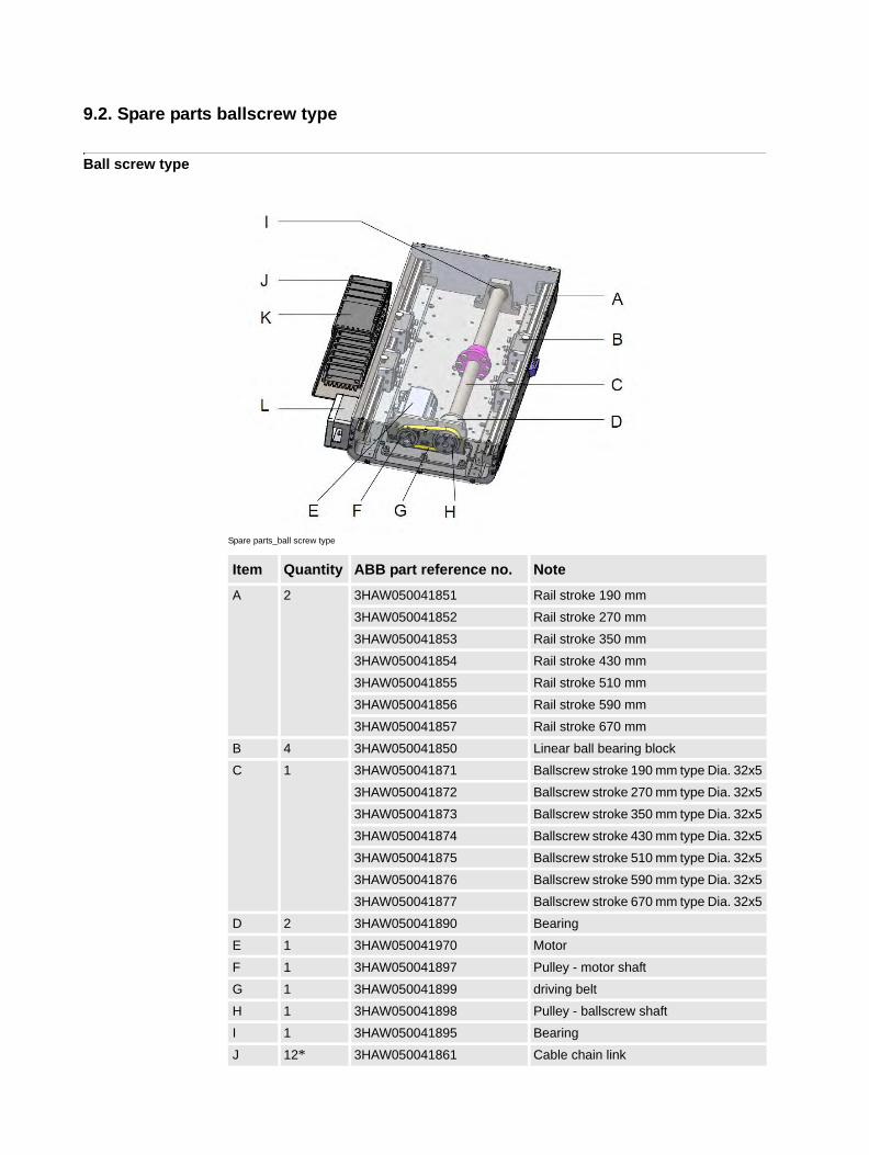
9.2. Spare parts ballscrew type
Ball screw type
Spare parts_ball screw type
Item Quantity ABB part reference no. Note
A 2 3HAW050041851 Rail stroke 190 mm
3HAW050041852 Rail stroke 270 mm
3HAW050041853 Rail stroke 350 mm
3HAW050041854 Rail stroke 430 mm
3HAW050041855 Rail stroke 510 mm
3HAW050041856 Rail stroke 590 mm
3HAW050041857 Rail stroke 670 mm
B 4 3HAW050041850 Linear ball bearing block
C 1 3HAW050041871 Ballscrew stroke 190 mm type Dia. 32x5
3HAW050041872 Ballscrew stroke 270 mm type Dia. 32x5
3HAW050041873 Ballscrew stroke 350 mm type Dia. 32x5
3HAW050041874 Ballscrew stroke 430 mm type Dia. 32x5
3HAW050041875 Ballscrew stroke 510 mm type Dia. 32x5
3HAW050041876 Ballscrew stroke 590 mm type Dia. 32x5
3HAW050041877 Ballscrew stroke 670 mm type Dia. 32x5
D 2 3HAW050041890 Bearing
E 1 3HAW050041970 Motor
F 1 3HAW050041897 Pulley - motor shaft
G 1 3HAW050041899 driving belt
H 1 3HAW050041898 Pulley - ballscrew shaft
I 1 3HAW050041895 Bearing
J 12* 3HAW050041861 Cable chain link

9 Spare parts
9.2. Spare parts ballscrew type
*The number of chain links depend on strokes. 12 for stroke 190 mm, 14 for stroke 270 mm,
16 for stroke 350 mm, 17 for stroke 430mm, 19 for stroke 510 mm, 21 for stroke 590 mm, 23
for stroke 670 mm.
NOTE!
Contact ABB if you do not know whether your FlexPLP requires:
• Material for strokes
• Ballscrew type or Rack and Pinion type
K 1 3HAW050041864 Chain moving end
L 1 3HAW050041823 Cable box
Item Quantity ABB part reference no. Note
1033HAW050041018 Revision:-
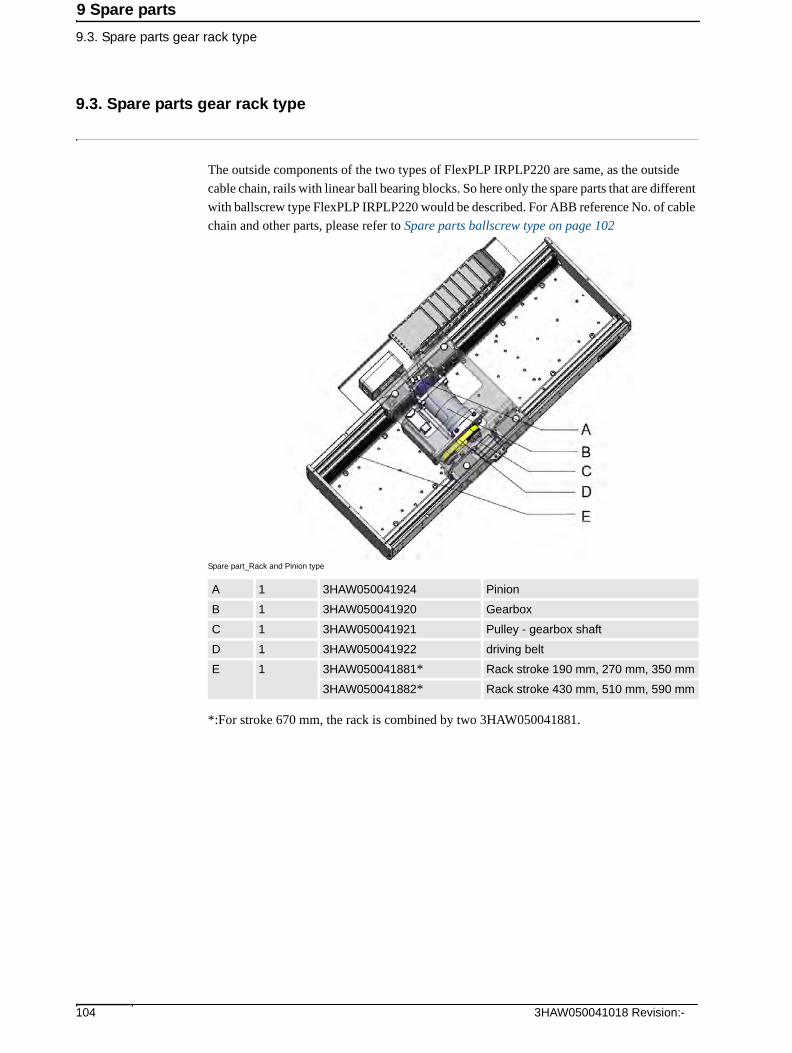
9 Spare parts
9.3. Spare parts gear rack type
9.3. Spare parts gear rack type
The outside components of the two types of FlexPLP IRPLP220 are same, as the outside
cable chain, rails with linear ball bearing blocks. So here only the spare parts that are different
with ballscrew type FlexPLP IRPLP220 would be described. For ABB reference No. of cable
chain and other parts, please refer to Spare parts ballscrew type on page 102
Spare part_Rack and Pinion type
*:For stroke 670 mm, the rack is combined by two 3HAW050041881.
A 1 3HAW050041924 Pinion
B 1 3HAW050041920 Gearbox
C 1 3HAW050041921 Pulley - gearbox shaft
D 1 3HAW050041922 driving belt
E 1 3HAW050041881* Rack stroke 190 mm, 270 mm, 350 mm
3HAW050041882* Rack stroke 430 mm, 510 mm, 590 mm
3HAW050041018 Revision:- 104

9 Spare parts
9.4. Covers
9.4. Covers
Covers
Covers
Item Quantity ABB part reference no. Note
A 1 per vertical axis
3HAW050041828 Flange frame tooling (For body moving axis)
B 1 per vertical axis
3HAW050041931 Interface Bracket stroke 190 mm
3HAW050041932 Interface Bracket stroke270 mm
3HAW050041933 Interface Bracket stroke 350 mm
3HAW050041934 Interface Bracket stroke 430 mm
3HAW050041935 Interface Bracket stroke510 mm
C 1 or 2 3HAW050041825 Cable tray
D 1 per axis 3HAW050041841 Cover stroke 190 mm
3HAW050041842 Cover stroke 270 mm
3HAW050041843 Cover stroke 350 mm
3HAW050041844 Cover stroke 430 mm
3HAW050041845 Cover stroke 510 mm
3HAW050041846 Cover stroke 590 mm
3HAW050041847 Cover stroke 670 mm
1053HAW050041018 Revision:-

9 Spare parts
9.5. Cables
9.5. Cables
Cables: from controller to SMB box
SMB boxes
Cables: from SMB box to mechanical unit
ABB part reference no. Description
3HAW050008612-005 6 axis resolver static cable XS41-2 5m
3HAW050008612-010 6 axis resolver static cable XS41-2 5m
3HAW050008612-015 6 axis resolver static cable XS41-2 10m
3HAW050008614-005 3 axis motor static cable XP7 400-600V 5m
3HAW050008614-010 3 axis motor static cable XP7 400-600V 10m
3HAW050008614-015 3 axis motor static cable XP7 400-600V 15m
3HAW050008616-005 6 axis motor static cable XP1 400V 5m
3HAW050008616-010 6 axis motor static cable XP1 400V 10m
3HAW050008616-015 6 axis motor static cable XP1 400V 15m
ABB part reference no. Description
3HAW050008651 SMB box 6 axis M2011 (Does not include board & battery! Order in addition 3HAC044168-001 and 3HAC044075-001)
3HAW050008605 SMB box 3 axis M2008 (Does not include board & battery! Order in addition 3HAC044168-001 and 3HAC044075-001)
3HAC044168-001 Main board for SMB box
3HAC044075-001 Battery for SMB box
3HAW050008607 PTC Shunt M2008
Quantity ABB part reference no. Description
1 per axis 3HAW050041981-002 1 Resolver Static M2008 2m
1 per axis 3HAW050041981-005 1 Resolver Static M2008 5m
1 per axis 3HAW050041981-010 1 Resolver Static M2008 10m
1 per axis 3HAW050041981-015 1 Resolver Static M2008 15m
1 per axis 3HAW050041980-002 1 Motor Static or Extension M2008 2m
1 per axis 3HAW050041980-005 1 Motor Static or Extension M2008 5m
1 per axis 3HAW050041980-010 1 Motor Static or Extension M2008 10m
1 per axis 3HAW050041980-015 1 Motor Static or Extension M2008 15m
3HAW050041018 Revision:- 106

9 Spare parts
9.5. Cables
1073HAW050041018 Revision:-


3HA
W05
0041
018,
Rev
1,en
Contact us
ABB Engineering (Shanghai) Ltd.Discrete Automation and Motion RoboticsNo.4528, Kangxin Highway, Kangqiao Town, PuDong District, SHANGHAI 201319, China Telephone: +86 (0) 21 6105 6666
www.abb.com