Product Manual ABB i-bus EIB Universal Interfaces US/U 4.2 ... · Product Manual ABB i-bus® EIB...
66
Product Manual ABB i-bus ® EIB Universal Interfaces US/U 4.2 US/U 2.2 Intelligent Installation Systems Intelligent and limitless
Transcript of Product Manual ABB i-bus EIB Universal Interfaces US/U 4.2 ... · Product Manual ABB i-bus® EIB...
Product Manual ABB i-bus® EIBUniversal InterfacesUS/U 4.2US/U 2.2
Intelligent Installation Systems
Intelligent andlimitless
Contents
1
Page
1 General . . . . . . . . . . . . . . . . . . . . . . . . . . . . . . . . . . . . . . . . . . . . . 3
1.1 Product and functional overview . . . . . . . . . . . . . . . . . . . . . . . . . . 3
2 Device technology . . . . . . . . . . . . . . . . . . . . . . . . . . . . . . . . . . . . 4
2.1 Technical data . . . . . . . . . . . . . . . . . . . . . . . . . . . . . . . . . . . . . . . . 4
2.2 Device connection . . . . . . . . . . . . . . . . . . . . . . . . . . . . . . . . . . . . . 5
2.3 Description of the inputs and outputs . . . . . . . . . . . . . . . . . . . . . . 6
2.4 Assembly and installation . . . . . . . . . . . . . . . . . . . . . . . . . . . . . . . 6
3 Function and operation . . . . . . . . . . . . . . . . . . . . . . . . . . . . . . . 7
4 Project design and programming . . . . . . . . . . . . . . . . . . . . . . . 8
4.1 Overview of the functions . . . . . . . . . . . . . . . . . . . . . . . . . . . . . . . 8
4.2 Overview of the communication objects . . . . . . . . . . . . . . . . . . . . 9
4.3 General functions . . . . . . . . . . . . . . . . . . . . . . . . . . . . . . . . . . . . . 94.3.1 General parameters . . . . . . . . . . . . . . . . . . . . . . . . . . . . . 94.3.2 General communication objects . . . . . . . . . . . . . . . . . . . . 10
4.4 Function: “Switch sensor” . . . . . . . . . . . . . . . . . . . . . . . . . . . . . . . 114.4.1 Parameters . . . . . . . . . . . . . . . . . . . . . . . . . . . . . . . . . . . . 114.4.2 Communication objects . . . . . . . . . . . . . . . . . . . . . . . . . . 13
4.5 Function: “Switch/dimming sensor” . . . . . . . . . . . . . . . . . . . . . . . . 144.5.1 Parameters . . . . . . . . . . . . . . . . . . . . . . . . . . . . . . . . . . . . 144.5.2 Communication objects . . . . . . . . . . . . . . . . . . . . . . . . . . 15
4.6 Function: “Shutter sensor” . . . . . . . . . . . . . . . . . . . . . . . . . . . . . . . 174.6.1 Parameters . . . . . . . . . . . . . . . . . . . . . . . . . . . . . . . . . . . . 174.6.2 Communication objects . . . . . . . . . . . . . . . . . . . . . . . . . . 19
4.7 Function: “Value / forced operation” . . . . . . . . . . . . . . . . . . . . . . . 204.7.1 Parameters . . . . . . . . . . . . . . . . . . . . . . . . . . . . . . . . . . . . 204.7.2 Communication objects . . . . . . . . . . . . . . . . . . . . . . . . . . 21
4.8 Function: “Control scene” . . . . . . . . . . . . . . . . . . . . . . . . . . . . . . . 234.8.1 Parameters . . . . . . . . . . . . . . . . . . . . . . . . . . . . . . . . . . . . 234.8.2 Communication objects . . . . . . . . . . . . . . . . . . . . . . . . . . 25
4.9 Function: “Control electronic relay (heating actuator)” . . . . . . . . . 274.9.1 Parameters . . . . . . . . . . . . . . . . . . . . . . . . . . . . . . . . . . . . 274.9.2 Communication objects . . . . . . . . . . . . . . . . . . . . . . . . . . 29
4.10 Function: “Control LED” . . . . . . . . . . . . . . . . . . . . . . . . . . . . . . . . . 314.10.1 Parameters . . . . . . . . . . . . . . . . . . . . . . . . . . . . . . . . . . . . 314.10.2 Communication objects . . . . . . . . . . . . . . . . . . . . . . . . . . 32
4.11 Function: “Switching sequence” . . . . . . . . . . . . . . . . . . . . . . . . . . 334.11.1 Parameters . . . . . . . . . . . . . . . . . . . . . . . . . . . . . . . . . . . . 334.11.2 Communication objects . . . . . . . . . . . . . . . . . . . . . . . . . . 34
4.12 Function: “Push button with multiple operation” . . . . . . . . . . . . . . 354.12.1 Parameters . . . . . . . . . . . . . . . . . . . . . . . . . . . . . . . . . . . . 354.12.2 Communication objects . . . . . . . . . . . . . . . . . . . . . . . . . . 36
4.13 Function: “Counter” . . . . . . . . . . . . . . . . . . . . . . . . . . . . . . . . . . . . 374.13.1 Parameters . . . . . . . . . . . . . . . . . . . . . . . . . . . . . . . . . . . . 374.13.2 Communication objects . . . . . . . . . . . . . . . . . . . . . . . . . . 39
4.14 Programming . . . . . . . . . . . . . . . . . . . . . . . . . . . . . . . . . . . . . . . . . 40
2
Contents
Seite
5 Special functions . . . . . . . . . . . . . . . . . . . . . . . . . . . . . . . . . . . . . 41
5.1 Debounce time and minimum operation time . . . . . . . . . . . . . . . . 41
5.2 Limit telegram rate . . . . . . . . . . . . . . . . . . . . . . . . . . . . . . . . . . . . . 42
5.3 Cyclical sending . . . . . . . . . . . . . . . . . . . . . . . . . . . . . . . . . . . . . . . 42
5.4 Dimming . . . . . . . . . . . . . . . . . . . . . . . . . . . . . . . . . . . . . . . . . . . . . 42
5.5 Scene control . . . . . . . . . . . . . . . . . . . . . . . . . . . . . . . . . . . . . . . . . 43
5.6 Control of electronic relay (heating actuator) . . . . . . . . . . . . . . . . 43
5.7 Switching sequences . . . . . . . . . . . . . . . . . . . . . . . . . . . . . . . . . . . 45
5.8 Pulse counter . . . . . . . . . . . . . . . . . . . . . . . . . . . . . . . . . . . . . . . . . 46
5.9 Behaviour during bus voltage failure . . . . . . . . . . . . . . . . . . . . . . . 47
5.10 Behaviour after bus voltage recovery . . . . . . . . . . . . . . . . . . . . . . 47
6 Planning and application . . . . . . . . . . . . . . . . . . . . . . . . . . . . . . 49
6.1 1 push button operation with central function (switch lamp) . . . . . 49
6.2 Operation of dimmable lighting . . . . . . . . . . . . . . . . . . . . . . . . . . . 50
6.3 Operation of shutters . . . . . . . . . . . . . . . . . . . . . . . . . . . . . . . . . . . 51
6.4 Controlling scenes . . . . . . . . . . . . . . . . . . . . . . . . . . . . . . . . . . . . . 53
6.5 Controlling a heating valve . . . . . . . . . . . . . . . . . . . . . . . . . . . . . . 55
6.6 Switching the lighting in sequence . . . . . . . . . . . . . . . . . . . . . . . . 57
6.7 Switching the lighting via multiple push button operation . . . . . . . 59
6.8 Counting energy values . . . . . . . . . . . . . . . . . . . . . . . . . . . . . . . . . 60
7 Appendix . . . . . . . . . . . . . . . . . . . . . . . . . . . . . . . . . . . . . . . . . . . 61
7.1 Table of grey code . . . . . . . . . . . . . . . . . . . . . . . . . . . . . . . . . . . . . 61
7.2 Ordering information . . . . . . . . . . . . . . . . . . . . . . . . . . . . . . . . . . . 62
This manual describes the function of the universal interfaces US/U 2.2 andUS/U 4.2 with the application program “Binary Input Display Heat xf/1”.
Subject to technical changes. Errors excepted
Exclusion of liability:
Despite checking that the contents of this document correspond to the hard-ware and software, deviations cannot be ruled out completely. We thereforecannot accept liability for this. Any necessary corrections will be integrated innew versions of the manual.
Please tell us about any suggestions for improvement you may have.
1 General
1.1 Product and functionaloverview
The functions implemented in modern buildings with ABB i-bus® EIB shouldbe both simple to operate and intuitive. At the same time, clear and user-friendly operation is extremely important to the value of a building installation.
The universal interfaces US/U 2.2 and US/U 4.2 meet individual require-ments in both functional buildings and the residential sector. A variety ofapplication possibilities are thus available to the planner of the system asregards the implementation of functions.
This manual provides technical information about the device as well as itsassembly and programming. The last section contains application examplesfor its effective use on site.
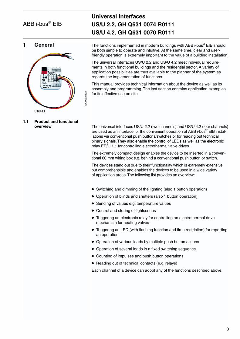
The universal interfaces US/U 2.2 (two channels) and US/U 4.2 (four channels)are used as an interface for the convenient operation of ABB i-bus® EIB instal-lations via conventional push buttons/switches or for reading out technicalbinary signals.They also enable the control of LEDs as well as the electronicrelay ER/U 1.1 for controlling electrothermal valve drives.
The extremely compact design enables the device to be inserted in a conven-tional 60 mm wiring box e.g. behind a conventional push button or switch.
The devices stand out due to their functionality which is extremely extensivebut comprehensible and enables the devices to be used in a wide variety of application areas.The following list provides an overview:
Switching and dimming of the lighting (also 1 button operation)
Operation of blinds and shutters (also 1 button operation)
Sending of values e.g. temperature values
Control and storing of lightscenes
Triggering an electronic relay for controlling an electrothermal drive mechanism for heating valves
Triggering an LED (with flashing function and time restriction) for reportingan operation
Operation of various loads by multiple push button actions
Operation of several loads in a fixed switching sequence
Counting of impulses and push button operations
Reading out of technical contacts (e.g. relays)
Each channel of a device can adopt any of the functions described above.
Universal InterfacesUS/U 2.2, GH Q631 0074 R0111US/U 4.2, GH Q631 0070 R0111
3
ABB i-bus® EIB
SK
009
3 B
02
US/U 4.2
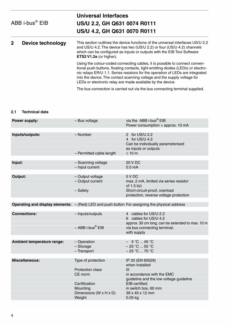
This section outlines the device functions of the universal interfaces US/U 2.2and US/U 4.2. The device has two (US/U 2.2) or four (US/U 4.2) channelswhich can be configured as inputs or outputs with the EIB Tool SoftwareETS2 V1.2a (or higher).
Using the colour-coded connecting cables, it is possible to connect conven-tional push buttons, floating contacts, light-emitting diodes (LEDs) or electro-nic relays ER/U 1.1. Series resistors for the operation of LEDs are integratedinto the device. The contact scanning voltage and the supply voltage forLEDs or electronic relay are made available by the device.
The bus connection is carried out via the bus connecting terminal supplied.
2 Device technology
2.1 Technical data
Universal InterfacesUS/U 2.2, GH Q631 0074 R0111US/U 4.2, GH Q631 0070 R0111
4
ABB i-bus® EIB
Power supply: – Bus voltage via the ABB i-bus® EIBPower consumption < approx. 10 mA
Inputs/outputs: – Number 2 for US/U 2.24 for US/U 4.2Can be individually parameterised as inputs or outputs
– Permitted cable length ≤ 10 m
Input: – Scanning voltage 20 V DC– Input current 0.5 mA
Output: – Output voltage 5 V DC– Output current max. 2 mA, limited via series resistor
of 1.5 kΩ– Safety Short-circuit-proof, overload
protection, reverse voltage protection
Operating and display elements: – (Red) LED and push button For assigning the physical address
Connections: – Inputs/outputs 4 cables for US/U 2.26 cables for US/U 4.2approx. 30 cm long, can be extended to max. 10 m
– ABB i-bus® EIB via bus connecting terminal,with supply
Ambient temperature range: – Operation – 5 °C ... 45 °C– Storage – 25 °C ... 55 °C– Transport – 25 °C ... 70 °C
Miscellaneous: Type of protection IP 20 (EN 60529) when installed
Protection class IIICE norm in accordance with the EMC
guideline and the low voltage guidelineCertification EIB-certifiedMounting in switch box, 60 mmDimensions (W x H x D) 39 x 40 x 12 mmWeight 0.05 kg

During operation as an input, the scanned contact is connected betweenthe grey core and the coloured core.
During operation as an output, the load (LED or electronic relay) is connec-ted between the black and the coloured core. The coloured core representsthe positive output voltage.
Note: When connecting to an S0 impulse output (e.g. an energyconsumption meter), it must be ensured that it is electricallyisolated from the mains. The correct polarity should also beobserved (“+” on the grey core).
Connection of a floating push button/switch
coloured / farbig
grey / grau
Connection of an electronic relay
coloured / farbig
black /schwarz
Connection of an LED
coloured / farbig
black / schwarz
2 mA
2.2 Device connection
Universal InterfacesUS/U 2.2, GH Q631 0074 R0111US/U 4.2, GH Q631 0070 R0111
5
ABB i-bus® EIB

Grey core: Positive scanning voltage
During operation as an input, the grey core makes the positive, pulsed scanning voltage available.
Coloured core: Control of the channel
During operation as an input, the status of the contact is read out via thecoloured cores.
During operation as an output, the coloured core makes the positive outputvoltage available.
The following table allocates the colours to the channels:
brown Channel A
red Channel B
orange* Channel C
yellow* Channel D
*only for US/U 4.2
Black core: Negative reference potential
During operation as an output, the black core makes the negative referencepotential available.
Important: The inputs and outputs do not have electrical isolation to the EIB bus voltage (SELV). The SELV criteria only enablethe connection of floating contacts with safety separation.
The device can in mounted in any position. Any cores that are not requiredmust be insulated.
2.3 Description of the inputsand outputs
2.4 Assembly and installation
Universal InterfacesUS/U 2.2, GH Q631 0074 R0111US/U 4.2, GH Q631 0070 R0111
6
ABB i-bus® EIB

3 Function and operation
This section does not apply.
Universal InterfacesUS/U 2.2, GH Q631 0074 R0111US/U 4.2, GH Q631 0070 R0111
7
ABB i-bus® EIB
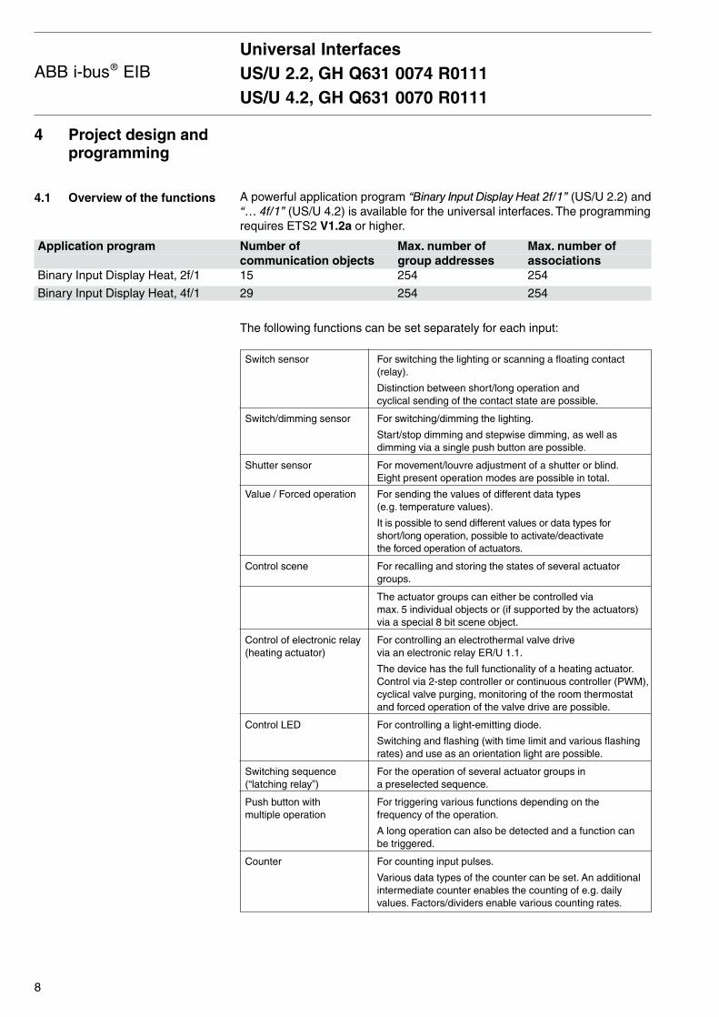
A powerful application program “Binary Input Display Heat 2f/1” (US/U 2.2) and“… 4f/1” (US/U 4.2) is available for the universal interfaces. The programmingrequires ETS2 V1.2a or higher.
The following functions can be set separately for each input:
Switch sensor For switching the lighting or scanning a floating contact(relay).
Distinction between short/long operation and cyclical sending of the contact state are possible.
Switch/dimming sensor For switching/dimming the lighting.
Start/stop dimming and stepwise dimming, as well asdimming via a single push button are possible.
Shutter sensor For movement/louvre adjustment of a shutter or blind.Eight present operation modes are possible in total.
Value / Forced operation For sending the values of different data types (e.g. temperature values).
It is possible to send different values or data types forshort/long operation, possible to activate/deactivate the forced operation of actuators.
Control scene For recalling and storing the states of several actuatorgroups.
The actuator groups can either be controlled via max. 5 individual objects or (if supported by the actuators)via a special 8 bit scene object.
Control of electronic relay For controlling an electrothermal valve drive (heating actuator) via an electronic relay ER/U 1.1.
The device has the full functionality of a heating actuator.Control via 2-step controller or continuous controller (PWM),cyclical valve purging, monitoring of the room thermostatand forced operation of the valve drive are possible.
Control LED For controlling a light-emitting diode.
Switching and flashing (with time limit and various flashingrates) and use as an orientation light are possible.
Switching sequence For the operation of several actuator groups in (“latching relay”) a preselected sequence.
Push button with For triggering various functions depending on the multiple operation frequency of the operation.
A long operation can also be detected and a function can be triggered.
Counter For counting input pulses.
Various data types of the counter can be set. An additionalintermediate counter enables the counting of e.g. dailyvalues. Factors/dividers enable various counting rates.
4 Project design andprogramming
4.1 Overview of the functions
Universal InterfacesUS/U 2.2, GH Q631 0074 R0111US/U 4.2, GH Q631 0070 R0111
8
ABB i-bus® EIB
Application program Number of Max. number of Max. number ofcommunication objects group addresses associations
Binary Input Display Heat, 2f/1 15 254 254
Binary Input Display Heat, 4f/1 29 254 254
4.2 Overview of the communication objects
4.3 General functions
4.3.1 General parameters
Both the communication objects and the objects are identical for each channel.
Parameters and objects, which apply to the device as a whole, are outlined in this section.
Parameters and objects which are assigned to each channel, are describedin the following sections using output A as an example.
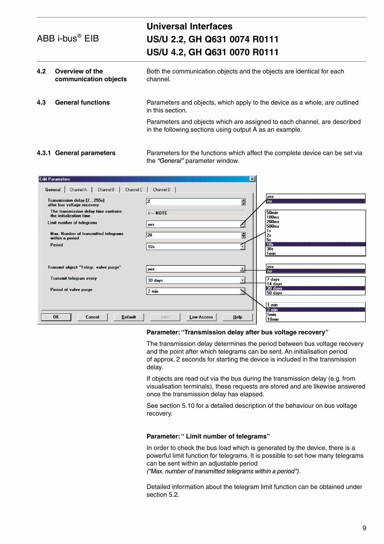
Parameters for the functions which affect the complete device can be set viathe “General” parameter window.
Parameter: “Transmission delay after bus voltage recovery”
The transmission delay determines the period between bus voltage recoveryand the point after which telegrams can be sent. An initialisation period of approx. 2 seconds for starting the device is included in the transmissiondelay.
If objects are read out via the bus during the transmission delay (e.g. fromvisualisation terminals), these requests are stored and are likewise answeredonce the transmission delay has elapsed.
See section 5.10 for a detailed description of the behaviour on bus voltagerecovery.
Parameter: “ Limit number of telegrams”
In order to check the bus load which is generated by the device, there is apowerful limit function for telegrams. It is possible to set how many telegramscan be sent within an adjustable period (“Max. number of transmitted telegrams within a period”).
Detailed information about the telegram limit function can be obtained undersection 5.2.
Universal InterfacesUS/U 2.2, GH Q631 0074 R0111US/U 4.2, GH Q631 0070 R0111
9
ABB i-bus® EIB
Parameter: “Transmit object ‘Telegr. valve purge’”
This function is only relevant if one or several channels are used to control an electronic relay. Regular purging of a heating control valve can preventdeposits from building up in the valve thereby restricting the valve function.This is particularly significant during periods when only a few changes aremade to the valve position.
If this parameter is set to “yes”, the object “Telegr. trigger valve purge” isvisible. It is sent at adjustable intervals to start the valve purge (“Transmit telegram every”) and has the value “1” for the “Period of valvepurge”. The “Valve purge” object of a channel which has been assigned thefunction of a heating actuator can be controlled via this object.
Object “Disable”: 1 bit (EIS 1)
This object is visible for each channel that is operated as an input.
The function of the protective input circuit can be disabled or enabled viathe “Disable” object. A disabled input behaves as if a change in the inputsignal has not taken place. The objects of the input remain available.
If the input is disabled during operation, the behaviour is undefined.
When a disabled input is enabled, no telegrams are initially sent on the bus,even if the status of the input has changed during the blocking. If the input isoperated when it is enabled, it behaves as if the operation had started withthe end of the blocking.
Telegram value “0”: Enable input
“1”: Disable input
Object “Telegr. trigger valve purge”: 1 bit (EIS 1)
This object is visible if the parameter “Transmit object ‘Telegr. valve purge’” is set to “yes”.
The object is set at regular intervals to the value “1” for an adjustable periodand then reset to “0”.
It can be used for example to trigger a valve purge at regular intervals (see “Valve purge” object).
After bus voltage recovery, this object sends the value “0” to the bus and thepurge cycle is restarted.
4.3.2 General communication objects
Universal InterfacesUS/U 2.2, GH Q631 0074 R0111US/U 4.2, GH Q631 0070 R0111
10
ABB i-bus® EIB
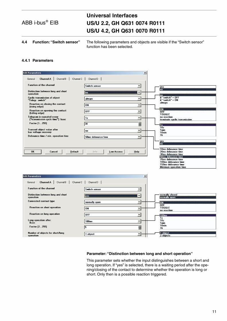
The following parameters and objects are visible if the “Switch sensor”function has been selected.
Parameter: “Distinction between long and short operation”
This parameter sets whether the input distinguishes between a short andlong operation. If “yes” is selected, there is a waiting period after the ope-ning/closing of the contact to determine whether the operation is long orshort. Only then is a possible reaction triggered.
Universal InterfacesUS/U 2.2, GH Q631 0074 R0111US/U 4.2, GH Q631 0070 R0111
11
ABB i-bus® EIB
4.4 Function: “Switch sensor”
4.4.1 Parameters
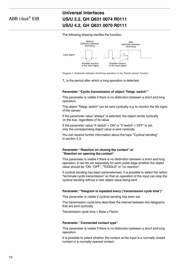
The following drawing clarifies the function:
Diagram 1: Distinction between short/long operation in the “Switch sensor” function
TL is the period after which a long operation is detected.
Parameter: “Cyclic transmission of object ‘Telegr. switch’”
This parameter is visible if there is no distinction between a short and longoperation.
The object “Telegr. switch” can be sent cyclically e.g. to monitor the life signsof the sensor.
If the parameter value “always” is selected, the object sends cyclically on the bus, regardless of its value.
If the parameter value “if ‘switch’ = ON” or “if ‘switch’ = OFF” is set,only the corresponding object value is sent cyclically.
You can receive further information about the topic “Cyclical sending”in section 5.3.
Parameter: “Reaction on closing the contact” or “Reaction on opening the contact”
This parameter is visible if there is no distinction between a short and longoperation. It can be set separately for each pulse edge whether the objectvalue should be “ON, “OFF”, “TOGGLE” or “no reaction”.
If cyclical sending has been parameterised, it is possible to select the option“terminate cyclic transmission” so that an operation of the input can stop thecyclical sending without a new object value being sent.
Parameter: “Telegram is repeated every (‘transmission cycle time’)”
This parameter is visible if cyclical sending has been set.
The transmission cycle time describes the interval between two telegramsthat are sent cyclically.
Transmission cycle time = Base x Factor.
Parameter: “Connected contact type”
This parameter is visible if there is no distinction between a short and longoperation.
It is possible to select whether the contact at the input is a normally closedcontact or a normally opened contact.
Universal InterfacesUS/U 2.2, GH Q631 0074 R0111US/U 4.2, GH Q631 0070 R0111
12
ABB i-bus® EIB
Withdistinction between
short/long
TLInput signal
Possible reactionto the input signal
Possible reactionto the input signal
Withoutdistinction between
short/long

4.4.2 Communication objects
Parameter: “Reaction on short operation” or “Reaction on long operation”
This parameter is visible if there is no distinction between a short and longoperation.
It can be set for each operation at the input (short or long) how the objectvalue is changed. The object value is updated as soon as it is establishedwhether the operation is long or short.
Parameter: “Long operation after”
This parameter is visible if there is a distinction between a short and longoperation. The period TL is defined here, after which an operation is interpre-ted as “long”.
TL = Base x Factor.
Parameter: “Number of objects for short/long operation”
This parameter is visible if there is a distinction between a short and longoperation.
To differentiate between short and long operations, it is possible to activatea further object by setting the parameter value “2 objects” which reacts solelyto long operations.
Parameter: “Transmit object value after bus voltage recovery”
This parameter is only visible if there is no distinction between a short andlong operation.
It can be set whether the current status of the input is sent on the bus (object“Telegr. switch”) after bus voltage recovery (once the transmission delay haselapsed).
A value is however only sent on the bus if the value “TOGGLE” has not beenset in either of the two parameters “Reaction on opening/closing the contact”.If one of the two parameters has the value “TOGGLE”, no values are sent ingeneral on the bus after bus voltage recovery.
Parameter: “Debounce time / min. operation time”
The debounce prevents unwanted multiple operation of the input e.g. bybouncing of the contacts. Refer to section 5.1 for the exact function of thisparameter. A minimum operation time can only be set if there is no distinctionbetween a short and long operation.
Object: “Telegr. switch”, 1 bit (EIS 1)
According to the parameter setting, it is possible for this object to be switchedon, switched off or toggled via an operation of the input.
If the parameter “Distinction between long and short operation” is set to “yes”and the parameter “Number of objects for short/long operation” is set to “2 objects”, two separate objects are made available. The second object isassigned to long operations.
Universal InterfacesUS/U 2.2, GH Q631 0074 R0111US/U 4.2, GH Q631 0070 R0111
13
ABB i-bus® EIB
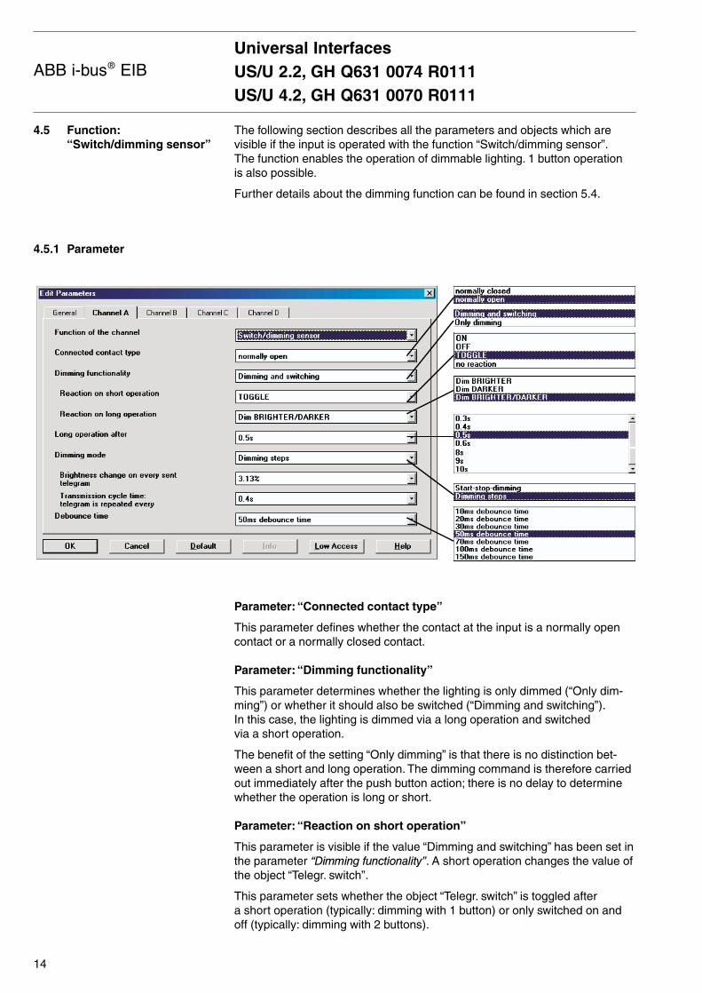
The following section describes all the parameters and objects which arevisible if the input is operated with the function “Switch/dimming sensor”.The function enables the operation of dimmable lighting. 1 button operation is also possible.
Further details about the dimming function can be found in section 5.4.
Parameter: “Connected contact type”
This parameter defines whether the contact at the input is a normally opencontact or a normally closed contact.
Parameter: “Dimming functionality”
This parameter determines whether the lighting is only dimmed (“Only dim-ming”) or whether it should also be switched (“Dimming and switching”).In this case, the lighting is dimmed via a long operation and switched via a short operation.
The benefit of the setting “Only dimming” is that there is no distinction bet-ween a short and long operation. The dimming command is therefore carriedout immediately after the push button action; there is no delay to determinewhether the operation is long or short.
Parameter: “Reaction on short operation”
This parameter is visible if the value “Dimming and switching” has been set inthe parameter “Dimming functionality”. A short operation changes the value ofthe object “Telegr. switch”.
This parameter sets whether the object “Telegr. switch” is toggled after a short operation (typically: dimming with 1 button) or only switched on andoff (typically: dimming with 2 buttons).
4.5 Function:“Switch/dimming sensor”
4.5.1 Parameter
Universal InterfacesUS/U 2.2, GH Q631 0074 R0111US/U 4.2, GH Q631 0070 R0111
14
ABB i-bus® EIB

Parameter: “Reaction on long operation”
This parameter is visible if the value “Dimming and switching” has been set in the parameter “Dimming functionality”. A long operation changes the valueof the object “Telegr. dimming”.
This parameter sets whether the object “Telegr. dimming” sends a dim brigh-ter or a dim darker telegram after a long operation. The setting “Dim BRIGH-TER/DARKER” must be selected for dimming with 1 button. The oppositedimming command to the last command is sent in this case.
Parameter: “Long operation after”
This parameter is visible if the value “Dimming and switching” has been set in the parameter “Dimming functionality”. The period TL is defined here, afterwhich an operation is interpreted as “long”.
Parameter: “Reaction on operation”
This parameter is visible if the value “Only dimming” has been set in theparameter “Dimming functionality”. There is no distinction between a shortand long operation. The meaning of the parameter settings corresponds tothose of the parameter “Reaction on long operation” (see above).
Parameter: “Dimming mode”
Normal “Start-stop dimming” begins the dimming process with a dim darkeror brighter telegram and ends the dimming process with a stop telegram.Cyclical sending of the dimming telegram is not required in this case.
For “Dimming steps”, the dimming telegram is sent cyclically during a longoperation. Once the operation has finished, a stop telegram ends the dim-ming process.
Parameter: “Brightness change on every sent telegram”
This parameter is only visible for “Dimming steps”. It can be set, which chan-ge in brightness (percentage value) causes a dimming telegram to be sentcyclically.
Parameter: “Transmission cycle time: telegram is repeated every”
If “Dimming steps” has been set, the dimming telegram is sent cyclicallyduring a long operation. The transmission cycle time corresponds to theinterval between two telegrams during cyclical sending.
Parameter: “Debounce time / min. operation time”
The debounce prevents unwanted multiple operation of the input e.g. bybouncing of the contacts. Refer to section 5.1 for the exact function of thisparameter. A minimum operation time can only be set if the value “Only dimming” has been set in the parameter “Dimming functionality”.
Universal InterfacesUS/U 2.2, GH Q631 0074 R0111US/U 4.2, GH Q631 0070 R0111
15
ABB i-bus® EIB

Object: “Telegr. switch”, 1 bit (EIS 1)
This object is visible if the value “Switching and dimming” has been set in theparameter “Dimming functionality”.
Depending on the parameter setting, the object value can be switched on, off or toggled after a short operation. For dimming with 1 button, this objectshould be linked with the status response of the dimming actuator as a non-sending group address. The input is thus informed about the current swit-ching status of the dimming actuator.
Object: “Telegr. dimming”, 4 bit (EIS 2)
A long operation of the input causes a dim brighter or dim darker commandto be sent on the bus via this object. A stop command is sent at the end of this operation.
4.5.2 Communication objects
Universal InterfacesUS/U 2.2, GH Q631 0074 R0111US/U 4.2, GH Q631 0070 R0111
16
ABB i-bus® EIB
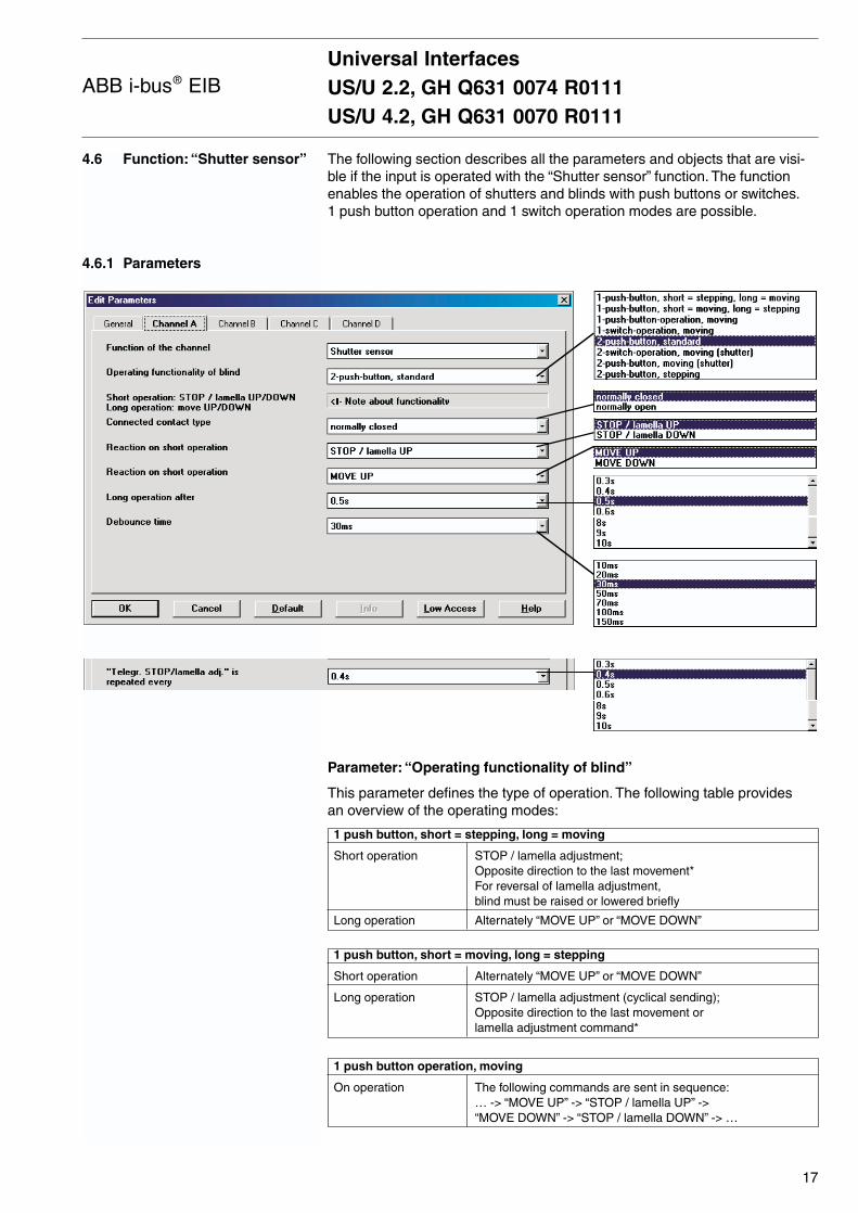
The following section describes all the parameters and objects that are visi-ble if the input is operated with the “Shutter sensor” function. The functionenables the operation of shutters and blinds with push buttons or switches.1 push button operation and 1 switch operation modes are possible.
Parameter: “Operating functionality of blind”
This parameter defines the type of operation. The following table provides an overview of the operating modes:
1 push button, short = stepping, long = moving
Short operation STOP / lamella adjustment;Opposite direction to the last movement*For reversal of lamella adjustment, blind must be raised or lowered briefly
Long operation Alternately “MOVE UP” or “MOVE DOWN”
1 push button, short = moving, long = stepping
Short operation Alternately “MOVE UP” or “MOVE DOWN”
Long operation STOP / lamella adjustment (cyclical sending);Opposite direction to the last movement or lamella adjustment command*
1 push button operation, moving
On operation The following commands are sent in sequence:… -> “MOVE UP” -> “STOP / lamella UP” -> “MOVE DOWN” -> “STOP / lamella DOWN” -> …
4.6 Function: “Shutter sensor”
4.6.1 Parameters
Universal InterfacesUS/U 2.2, GH Q631 0074 R0111US/U 4.2, GH Q631 0070 R0111
17
ABB i-bus® EIB

1 switch operation, moving
Start of operation Alternately “MOVE UP” or “MOVE DOWN”
End of operation STOP / lamella adjustment*
* Note: If the actuator is in a limit position (see “Upper limit position”or “Lower limit position”), the direction of movement is preset.
In 1 push button/switch operation mode, the last direction of movement is determined via the last update of the object“Telegr. shutter UP/DOWN”.
2 push button, standard
Short operation “STOP / lamella UP” or “STOP / lamella DOWN”(can be parameterised)
Long operation “MOVE UP” or “MOVE DOWN” (can be parameterised)
2 switch operation, moving (shutter)
Start of operation “MOVE UP” or “MOVE DOWN” (can be parameterised)
End of operation “STOP / lamella UP” or “STOP / lamella DOWN”
2 push button, moving (shutter)
On operation The following commands are sent in sequence:… -> “MOVE UP” -> “STOP / lamella UP” -> … or“MOVE DOWN” -> “STOP / lamella DOWN” -> …
2 push button, stepping
On operation “STOP / lamella UP” or “STOP / lamella DOWN”
Parameter: “Connected contact type”
This parameter defines whether the contact at the input is a normally opencontact or a normally closed contact.
Parameter: “Reaction on operation”
This parameter is visible if there is no distinction between a short and longoperation. It can be set whether the input triggers commands for upwardmovement (“UP”) or downward movement (“DOWN”).
Parameter: “Reaction on short operation” or “Reaction on long operation”
This parameter is visible in all operating modes in which there is a distinctionbetween a short and long operation. It can be set whether the input triggerscommands for upward movement (“UP”) or downward movement (“DOWN”).
Parameter: “Long operation after”
This parameter is visible in all operating modes in which there is a distinctionbetween a short and long operation. The period which defines a long operati-on is set here.
Universal InterfacesUS/U 2.2, GH Q631 0074 R0111US/U 4.2, GH Q631 0070 R0111
18
ABB i-bus® EIB

4.6.2 Communications objects
Parameter: “’Telegr. “STOP/lamella adj.’ is repeated every”
This parameter is visible in operating modes in which the object “Telegr.STOP/lamella adj.” is sent cyclically on the bus during a long operation.The interval between two telegrams is set here.
Parameter: “Debounce time”
The debounce prevents unwanted multiple operation of the input e.g. bybouncing of the contacts. Refer to section 5.1 for the exact function of thisparameter.
Object: “Telegr. shutter UP/DOWN”, 1 bit (EIS 7)
This communication object sends a shutter movement command (UP orDOWN) on the bus. The device also recognises movement commands of another sensor via the receipt of telegrams.
Telegram value “0” UP“1” DOWN
Object: “Telegr. STOP/lamella adj.”, 1 bit (EIS 7)
This communication object sends a STOP or lamella adjustment telegram.
Telegram value “0” STOP / lamella UP“1” STOP / lamella DOWN
Object: “Upper limit position”, 1 bit (EIS 1)
The shutter actuator reports via this object whether it is located in the upperlimit position (“Blind open”).The object is intended for 1 push button operation.
Telegram value “0” No upper limit position“1” Upper limit position
Object: “Lower limit position”, 1 bit (EIS 1)
The shutter actuator reports via this object whether it is located in the lowerlimit position (“Blind closed”).The object is intended for 1 push button operation.
Telegram value “0” No lower limit position“1” Lower limit position
Universal InterfacesUS/U 2.2, GH Q631 0074 R0111US/U 4.2, GH Q631 0070 R0111
19
ABB i-bus® EIB
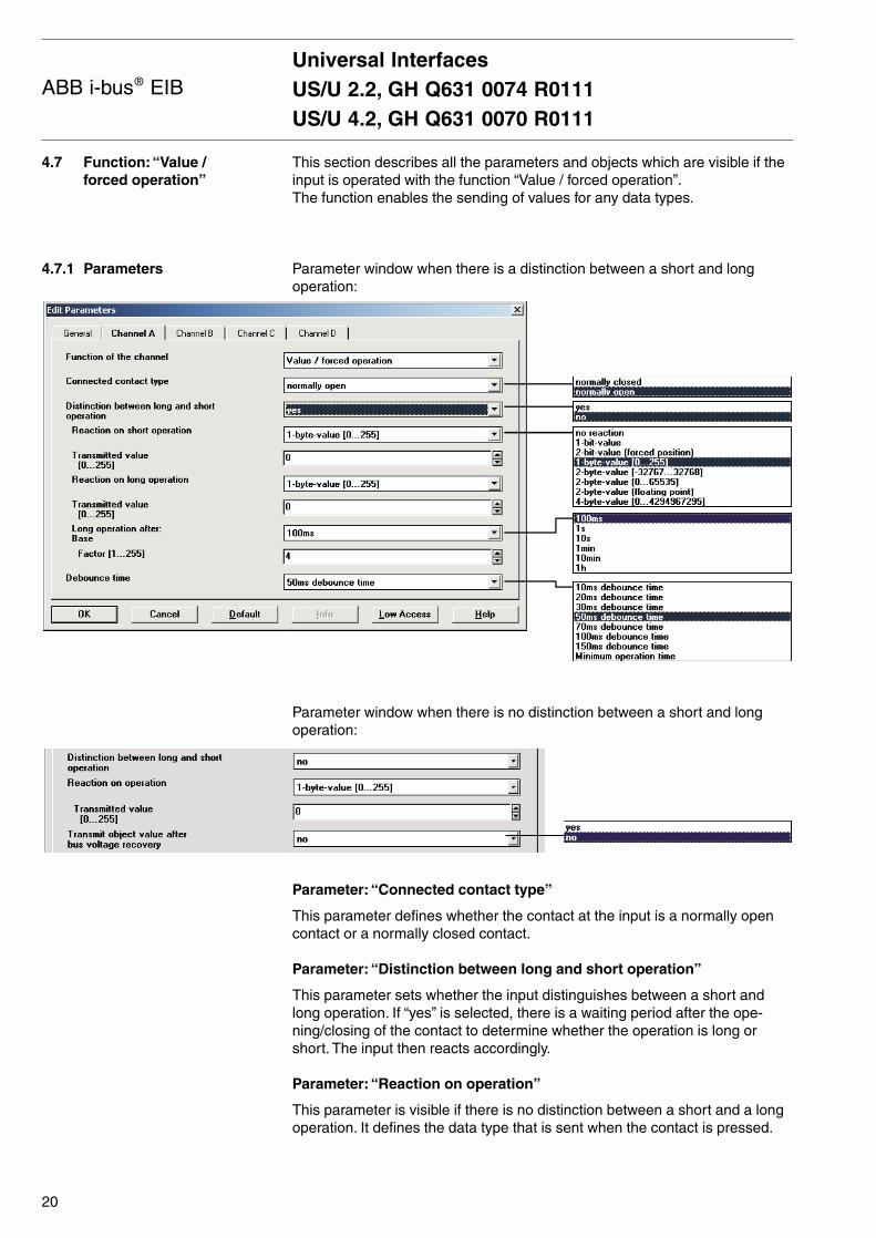
This section describes all the parameters and objects which are visible if theinput is operated with the function “Value / forced operation”.The function enables the sending of values for any data types.
Parameter window when there is a distinction between a short and longoperation:
Parameter window when there is no distinction between a short and longoperation:
Parameter: “Connected contact type”
This parameter defines whether the contact at the input is a normally opencontact or a normally closed contact.
Parameter: “Distinction between long and short operation”
This parameter sets whether the input distinguishes between a short andlong operation. If “yes” is selected, there is a waiting period after the ope-ning/closing of the contact to determine whether the operation is long orshort. The input then reacts accordingly.
Parameter: “Reaction on operation”
This parameter is visible if there is no distinction between a short and a longoperation. It defines the data type that is sent when the contact is pressed.
4.7 Function: “Value / forced operation”
4.7.1 Parameters
Universal InterfacesUS/U 2.2, GH Q631 0074 R0111US/U 4.2, GH Q631 0070 R0111
20
ABB i-bus® EIB
4.7.2 Communication objects
Parameter: “Reaction on short operation” or “Reaction on long operation”
This parameter is visible if there is no distinction between a short and longoperation. It defines the data type that is sent after a short or long operation.
Parameter: “Transmitted value”
This parameter defines the value which is sent on operation. The value rangeis dependent on the selected data type. Two values can be set here whenthere is a distinction between a short and long operation.
Parameter: “Long operation after”
This parameter is visible if there is a distinction between a short and longoperation. The period TL is defined here, after which an operation is interpre-ted as “long”.
TL = Base x Factor
Parameter: “Transmit object value after bus voltage recovery”
This parameter is visible if there is no distinction between a short and longoperation. If “yes” is selected, the device sends the object “Telegr. value”on the bus after bus voltage recovery (once the transmission delay has elapsed).
Parameter: “Debounce time / min. operation time”
The debounce prevents unwanted multiple operation of the input e.g. bybouncing of the contacts. Refer to section 5.1 for the exact function of thisparameter. A minimum operation time can only be set if there is no distinctionbetween a short and long operation.
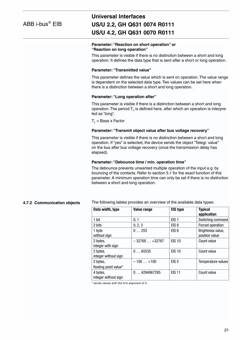
The following tables provides an overview of the available data types:
Data width, type Value range EIS type Typical application
1 bit 0, 1 EIS 1 Switching command2 bits 0, 2, 3 EIS 8 Forced operation1 byte 0 … 255 EIS 6 Brightness value,without sign position value2 bytes, – 32768 … +32767 EIS 10 Count valueinteger with sign2 bytes, 0 … 65535 EIS 10 Count valueinteger without sign2 bytes, – 100 … +100 EIS 5 Temperature valuesfloating point value*4 bytes, 0 … 4294967295 EIS 11 Count valueinteger without sign
* sends values with the firm exponent of 3
Universal InterfacesUS/U 2.2, GH Q631 0074 R0111US/U 4.2, GH Q631 0070 R0111
21
ABB i-bus® EIB

Object: “Telegr. value (…)” (various types)
This communication object sends a value on the bus when the contact is opened or closed. The value and data types can be freely selected in the parameters.
When there is a distinction between a short and long operation, 2 objects arevisible per input. One object only transmits a value after a short operationwhile the other object only sends after a long operation.
Note: By default, the “Write” flag is deleted for the value objects (except for the 1 bit objects). The object value cannot thus bemodified via the EIB. If this function is required, the “Write” flagmust be set in ETS. On bus voltage recovery, the object value is overwritten with the parameterised value.
Universal InterfacesUS/U 2.2, GH Q631 0074 R0111US/U 4.2, GH Q631 0070 R0111
22
ABB i-bus® EIB
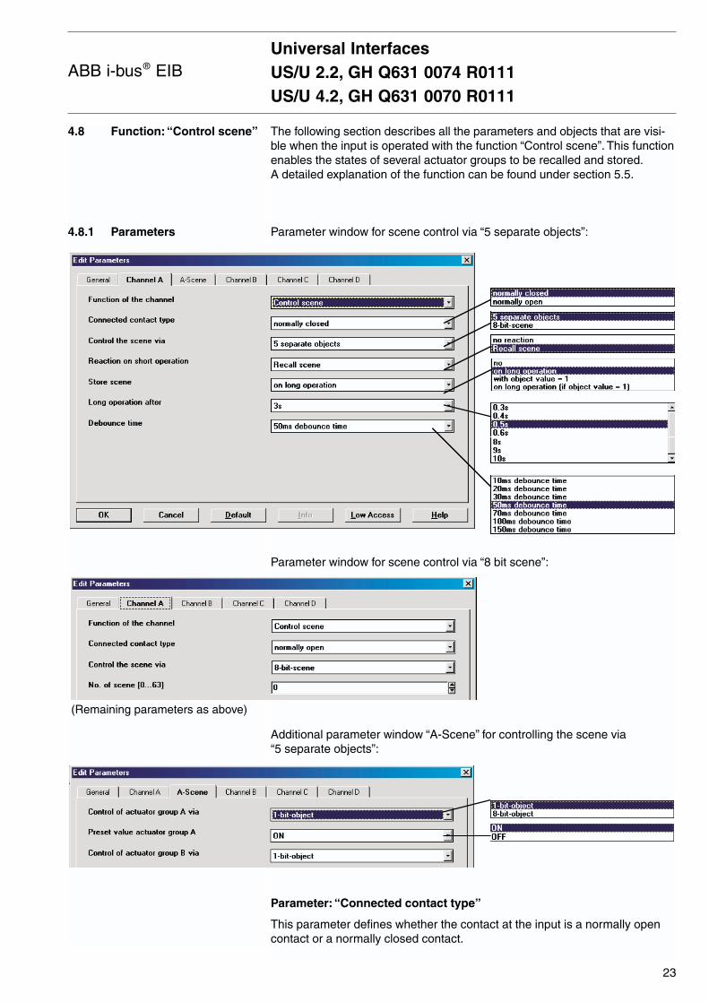
4.8 Function: “Control scene”
4.8.1 Parameters
The following section describes all the parameters and objects that are visi-ble when the input is operated with the function “Control scene”. This functionenables the states of several actuator groups to be recalled and stored.A detailed explanation of the function can be found under section 5.5.
Parameter window for scene control via “5 separate objects”:
Parameter window for scene control via “8 bit scene”:
Additional parameter window “A-Scene” for controlling the scene via “5 separate objects”:
Parameter: “Connected contact type”
This parameter defines whether the contact at the input is a normally opencontact or a normally closed contact.
Universal InterfacesUS/U 2.2, GH Q631 0074 R0111US/U 4.2, GH Q631 0070 R0111
23
ABB i-bus® EIB
(Remaining parameters as above)
Parameter: “Control the scene via”
It is possible to select whether the scene control is carried out via “5 separateobjects” or whether values that are stored in the actuators are recalled andsaved via an “8 bit scene” (see section 5.5 for further information).
Parameter: “Reaction on short operation”
This parameter defines whether a short operation of the input causes a lightscene to be recalled or no reaction takes place.
Parameter: “Store scene”
This parameter specifies how the saving of the current scene can be trigge-red and defines the function of the object “Store scene”. This is dependent onthe type of scene control. The following table provides an overview:
Control the scene via “5 separate objects”
Parameter value Behaviour
“on long operation” As soon as a long operation is detected, the object “Storescene” sends the value “1” on the bus and the object values“Telegr. switch/value actuator group A…E” are read out via the bus and stored in the object values.
The objects “Telegr. switch/value actuator group A…E” can bemodified via the bus for the duration of the long operation.
Once the long operation has finished, the object “Store scene” sends the value “0” on the bus and the currentobject values are stored in the device.
“if object value = 1” If the object “Store scene” receives the value “1”, the objectvalues “Telegr. switch/value actuator group A…E” are read outvia the bus.
While the object value is “1”, the objects “Telegr. switch/valueactuator group A…E” can be modified via the bus.
On receipt of the object value “0”, the current object valuesare stored in the device.
Important:
The storing of the current scene requires the object values “1” and “0” to be sent in succession.
“on long operation If the object “Store scene” receives the value “1” on the bus, (if object value = 1)” the next long push button action leads to the value “1” being
sent via the object “Store scene”.
The scanning of the object values “Telegr. switch/value actua-tor group A…E” is then carried out.
After the end of the long operation, the object values “Telegr.switch/value actuator group A…E” are stored in the device.
Provided that a “1” has not been received at the object “Storescene”, a long operation is interpreted in the same way as ashort operation. The same applies if the object “Store scene”has received the value “0”.
Universal InterfacesUS/U 2.2, GH Q631 0074 R0111US/U 4.2, GH Q631 0070 R0111
24
ABB i-bus® EIB
4.8.2 Communication objects
Control the scene via “8 bit scene”
Parameter value Behaviour
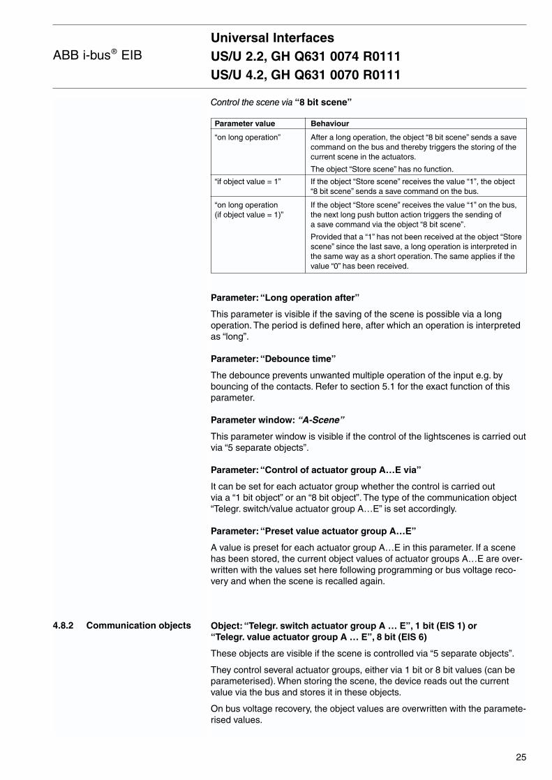
“on long operation” After a long operation, the object “8 bit scene” sends a savecommand on the bus and thereby triggers the storing of thecurrent scene in the actuators.
The object “Store scene” has no function.
“if object value = 1” If the object “Store scene” receives the value “1”, the object “8 bit scene” sends a save command on the bus.
“on long operation If the object “Store scene” receives the value “1” on the bus,(if object value = 1)” the next long push button action triggers the sending of
a save command via the object “8 bit scene”.
Provided that a “1” has not been received at the object “Storescene” since the last save, a long operation is interpreted inthe same way as a short operation. The same applies if thevalue “0” has been received.
Parameter: “Long operation after”
This parameter is visible if the saving of the scene is possible via a longoperation. The period is defined here, after which an operation is interpretedas “long”.
Parameter: “Debounce time”
The debounce prevents unwanted multiple operation of the input e.g. bybouncing of the contacts. Refer to section 5.1 for the exact function of thisparameter.
Parameter window: “A-Scene”
This parameter window is visible if the control of the lightscenes is carried outvia “5 separate objects”.
Parameter: “Control of actuator group A…E via”
It can be set for each actuator group whether the control is carried out via a “1 bit object” or an “8 bit object”. The type of the communication object “Telegr. switch/value actuator group A…E” is set accordingly.
Parameter: “Preset value actuator group A…E”
A value is preset for each actuator group A…E in this parameter. If a scenehas been stored, the current object values of actuator groups A…E are over-written with the values set here following programming or bus voltage reco-very and when the scene is recalled again.
Object: “Telegr. switch actuator group A … E”, 1 bit (EIS 1) or “Telegr. value actuator group A … E”, 8 bit (EIS 6)
These objects are visible if the scene is controlled via “5 separate objects”.
They control several actuator groups, either via 1 bit or 8 bit values (can beparameterised). When storing the scene, the device reads out the currentvalue via the bus and stores it in these objects.
On bus voltage recovery, the object values are overwritten with the paramete-rised values.
Universal InterfacesUS/U 2.2, GH Q631 0074 R0111US/U 4.2, GH Q631 0070 R0111
25
ABB i-bus® EIB
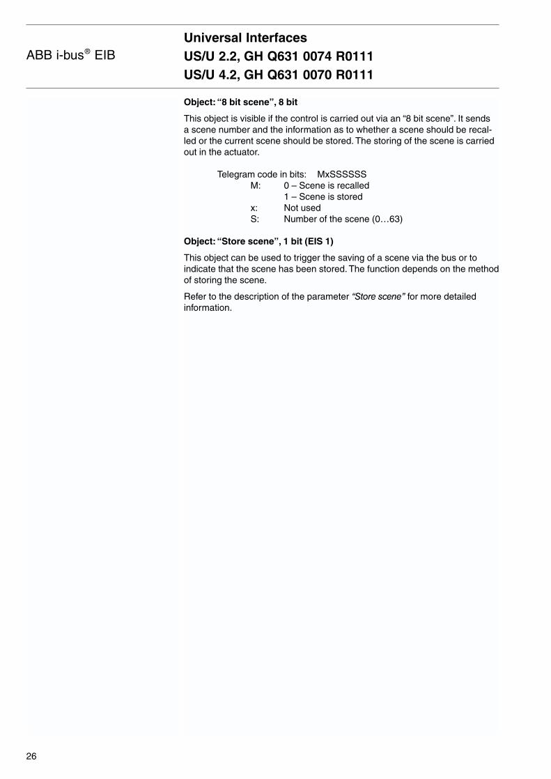
Object: “8 bit scene”, 8 bit
This object is visible if the control is carried out via an “8 bit scene”. It sends a scene number and the information as to whether a scene should be recal-led or the current scene should be stored. The storing of the scene is carriedout in the actuator.
Telegram code in bits: MxSSSSSSM: 0 – Scene is recalled
1 – Scene is storedx: Not usedS: Number of the scene (0…63)
Object: “Store scene”, 1 bit (EIS 1)
This object can be used to trigger the saving of a scene via the bus or toindicate that the scene has been stored. The function depends on the methodof storing the scene.
Refer to the description of the parameter “Store scene” for more detailedinformation.
Universal InterfacesUS/U 2.2, GH Q631 0074 R0111US/U 4.2, GH Q631 0070 R0111
26
ABB i-bus® EIB
4.9 Function:“Control electronic relay(heating actuator)”
4.9.1 Parameters
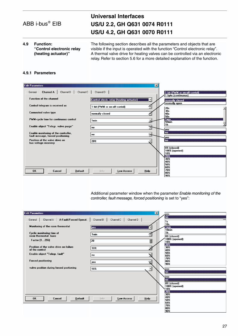
The following section describes all the parameters and objects that are visible if the input is operated with the function “Control electronic relay”.A thermal valve drive for heating valves can be controlled via an electronicrelay. Refer to section 5.6 for a more detailed explanation of the function.
Additional parameter window when the parameter Enable monitoring of thecontroller, fault message, forced positioning is set to “yes”:
Universal InterfacesUS/U 2.2, GH Q631 0074 R0111US/U 4.2, GH Q631 0070 R0111
27
ABB i-bus® EIB
Parameter: “Control telegram is received as”
The heating actuator can either be controlled via the 1 bit object “Telegr. switch” or the 1 byte object “Control value (PWM)”.
In the case of 1 bit control, the heating actuator functions in a similar way toa normal switch actuator: The room thermostat regulates the heating actuatorvia normal switching commands. It is thus possible to implement a simple 2-step closed-loop control or a pulse width modulation of the control value.
In the case of 1 byte control, a value of 0…255 (corresponds to 0%…100%)is preset by the room thermostat. This function is usually referred to as “continuous-action control”. The valve is closed at 0% and fully opened at 100%. The heating actuator controls intermediate values via pulse widthmodulation (see the graphic is section 5.6).
Parameter: “Connected valve type”
In this parameter, it is possible to set whether a valve is “de-energised closed” or “de-energised opened”. In the case of “de-energised closed”, the opening of the valve is achieved by closing the electronic relay whilethe process is reversed for “de-energised opened”.
Parameter: “PWM cycle time for continuous control”
When 1 byte control is selected, this parameter sets the PWM cycle timeTCYC which is used to time the control signal.
For 1 bit control and 1 byte control, this period is only used when the actuatoris controlled in fault mode, during forced positioning and directly after busvoltage recovery.
Parameter: “Enable object ‘Telegr. valve purge’”
The object “Valve purge” is enabled with this parameter.
Parameter:“Enable monitoring of the controller, fault message, forced positioning”
The parameter window “A-Fault-Forced Operat.” is enabled with this parame-ter. Further settings can be carried out in this window for the cyclical monito-ring of the room thermostat and for the forced positioning of the actuator.
Parameter: “Position of the valve drive on bus voltage recovery”
This parameter defines how the valve drive is controlled after bus voltagerecovery, until the first switching or positioning command of the room ther-mostat is received. The parameterised value is selected as the PWM cycletime.
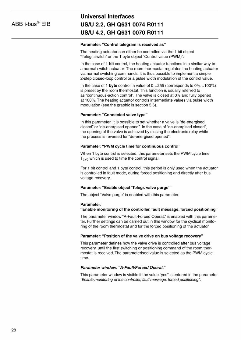
Parameter window: “A-Fault/Forced Operat.”
This parameter window is visible if the value “yes” is entered in the parameter“Enable monitoring of the controller, fault message, forced positioning”.
Universal InterfacesUS/U 2.2, GH Q631 0074 R0111US/U 4.2, GH Q631 0070 R0111
28
ABB i-bus® EIB
4.9.2 Communication objects
Parameter: “Monitoring of the room thermostat”
The cyclical monitoring of the room thermostat is enabled with this parame-ter.
The telegrams of the room thermostat are transmitted to the electronic actua-tor at specific cyclic intervals. If one or more of these telegram sequences is omitted, there may be a communications fault or a defect in the room thermostat. If no telegrams are sent to the objects “Telegr. switch” or “Controlvale (PWM)” for the duration of the cyclic monitoring time, the actuatorswitches to fault mode and triggers a safety position. The fault mode is finis-hed as soon as a telegram is received again.
Parameter: “Cyclic monitoring time of room thermostat”
The cyclic monitoring time for the telegrams of the room thermostat is set in this parameter.
Period = Base x Factor
Parameter: “Position of the valve drive on failure of the control”
This parameter defines the safety position which the actuator triggers in faultmode. The PWM cycle time TCYC of the control is defined in the parameter“Cycle time for continuous control”.
Parameter: “Enable object ‘Telegr. fault’”
The object “Telegr. fault” can be enabled in this parameter. It has the objectvalue “ON” during fault mode. If there is no fault, it has the object value“OFF”. The object is always sent cyclically. The cyclic transmission time is identical to the cyclic monitoring time.
Parameter: “Forced positioning”
This parameter enables the forced positioning function. During forced positio-ning, the actuator triggers a freely selectable forced positioning. This has thehighest priority i.e. it is not modified by a valve purge or a safety position.The forced positioning can be activated via the object “Forced positioning” = “ON” and deactivated via “Forced positioning” = “OFF”.
Parameter: “Valve position during forced positioning”
In this parameter, the valve position triggered by the actuator is definedduring the forced positioning. The PWM cycle time TCYC of the control is defined in the parameter “Cycle time for continuous control”.
Object: “Telegr. switch”, 1 bit (EIS 1)
This object is visible if the control of the heating actuator is carried out via a 1 bit object. If the object has the value “ON”, the valve is opened whilethe valve is closed if the object has the value “OFF”.
Telegram value: “0” Close valve“1” Open valve
Universal InterfacesUS/U 2.2, GH Q631 0074 R0111US/U 4.2, GH Q631 0070 R0111
29
ABB i-bus® EIB
Object: “Control value (PWM)”, 8 bit (EIS 6)
This object is visible if the control of the heating actuator is carried out via an 8 bit object e.g. during continuous control. The object value (0…255)determines the selection ratio (mark-to-space ratio) of the valve.
Telegram value: “0” Close valve“...” Mark-to-space ratio“255” Open valve
Object: “Valve purge”, 1 bit (EIS 1)
This object is visible if the parameter “Enable object ‘Telegr. valve purge’”has the value “yes”.
The valve purge of the device is activated or deactivated via this object.During the valve purge, the valve is controlled with “Open”.
Telegram value: “0” Stop valve purge“1” Start valve purge
Object: “Forced positioning”, 1 bit (EIS 1)
This object is visible if 1 bit forced positioning is enabled in the parameters.
The forced positioning of the device is activated or deactivated via this object.In this way, the valve can be controlled with a defined value. Forced positio-ning has the highest priority.
Telegram value: “0” Stop forced positioning “1” Start forced positioning
Object: “Telegr. status/ackn.”, 1 bit (EIS 1)
This object reports the switching state of the heating actuator.The object value is sent after each change of the output.
Telegram value: “0” Valve is closed“1” Valve is opened
Note: For PWM continuous control, this object is sent after each chan-ge in the output. The additional telegram load should thereforebe taken into account particularly if a short PWM cycle time hasbeen set.
Object: “Telegr. fault”, 1 bit (EIS 1)
This object is visible if the fault message has been enabled in the parame-ters.
If the output does not receive any telegrams from the room thermostat via the object “Telegr. switch” or “Control value (PWM)” for an adjustableperiod, the devices switches to fault mode and reports this via the object.
Telegram value: “0” No fault “1” Fault mode active
Universal InterfacesUS/U 2.2, GH Q631 0074 R0111US/U 4.2, GH Q631 0070 R0111
30
ABB i-bus® EIB
4.10 Function: “Control LED”
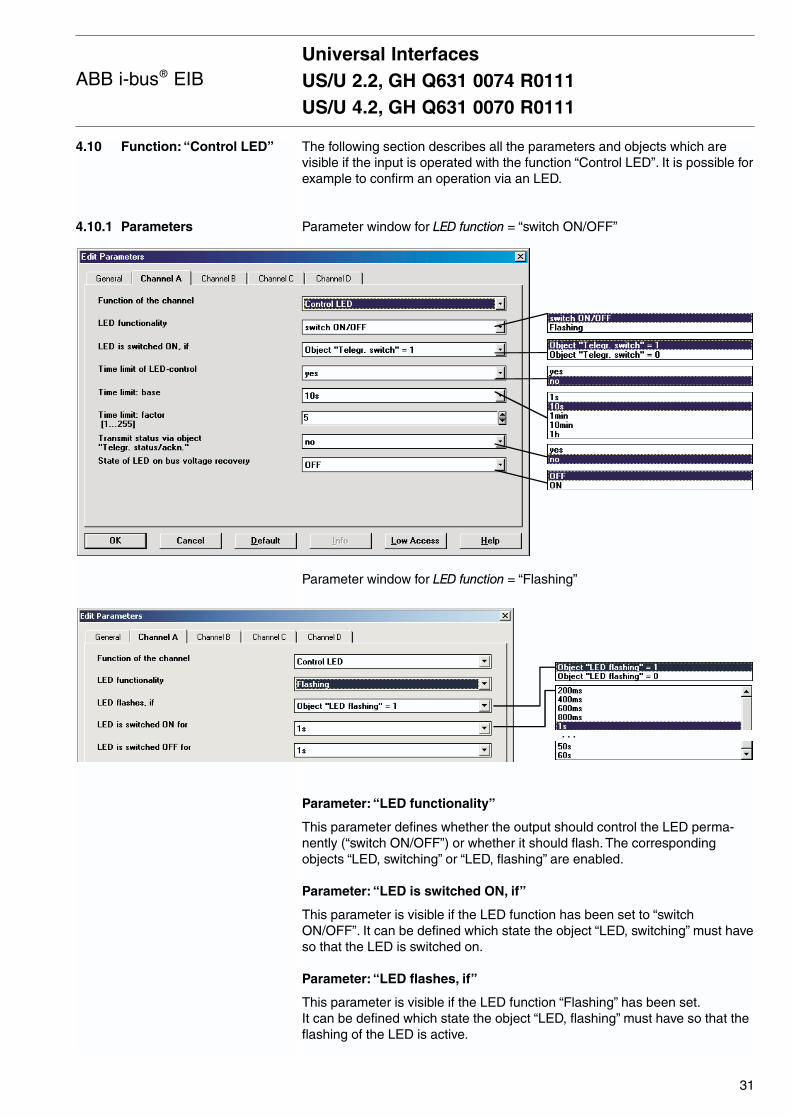
4.10.1 Parameters
The following section describes all the parameters and objects which arevisible if the input is operated with the function “Control LED”. It is possible forexample to confirm an operation via an LED.
Parameter window for LED function = “switch ON/OFF”
Parameter window for LED function = “Flashing”
Parameter: “LED functionality”
This parameter defines whether the output should control the LED perma-nently (“switch ON/OFF”) or whether it should flash. The corresponding objects “LED, switching” or “LED, flashing” are enabled.
Parameter: “LED is switched ON, if”
This parameter is visible if the LED function has been set to “switchON/OFF”. It can be defined which state the object “LED, switching” must haveso that the LED is switched on.
Parameter: “LED flashes, if”
This parameter is visible if the LED function “Flashing” has been set.It can be defined which state the object “LED, flashing” must have so that theflashing of the LED is active.
Universal InterfacesUS/U 2.2, GH Q631 0074 R0111US/U 4.2, GH Q631 0070 R0111
31
ABB i-bus® EIB
...
Parameter: “LED is switched ON for” or “LED is switched OFF for”
This parameter is visible if the LED function “Flashing” has been set.
It is defined how long the LED is switched on or switched off during the flashing signal. The flash rate of the signal can thus be set.
Parameter: “Time limit of LED control”
If “yes” has been entered in this parameter, the operating time or flashing of the LED has a time restriction.
Parameter: “Time limit” (Base/Factor)
If the time limit is active, it is possible to indicate in this parameter the maxi-mum period that an LED is switched on or flashes. Once this time limit haselapsed, the LED is switched off.
Period = Base x Factor
Parameter: “Transmit status via object ‘Telegr, status/ackn.’”
The object “Telegr. status/ackn.” Is enabled via this parameter. It indicateswith the value “ON” that the LED has been switched on or is flashing.
Object: “LED, switching”, 1 bit (EIS 1)
This object is visible if the parameter “LED function” has been set to “switch ON/OFF”. The object switches the LED on and off.The telegram values can be set in the parameters.
Object: “LED, flashing”, 1 bit (EIS 1)
This object is visible if the parameter “LED function” has been set to “Flashing”. The flashing of the LED can be started and stopped via this object.
Telegram value: “0” Stop flashing“1” Start flashing
Object: “LED, permanent ON”, 1 bit (EIS 1)
This object is visible if the parameter “LED function” has been set to “Flashing”.
The LED can be switched on permanently via this object.The flashing function is deactivated in this way.
Telegram value: “0” Flashing function active“1” LED permanently ON
Object: “Telegr. status/ackn.”, 1 bit (EIS 1)
This object is visible if the value “yes” has been set in the parameter “Transmit status via …”. It reports the status of the output.
Telegram value: “0” LED is switched off“1” LED is switched on or flashes
4.10.2 Communication objects
Universal InterfacesUS/U 2.2, GH Q631 0074 R0111US/U 4.2, GH Q631 0070 R0111
32
ABB i-bus® EIB
4.11 Function:“Switching sequence”
4.11.1 Parameters
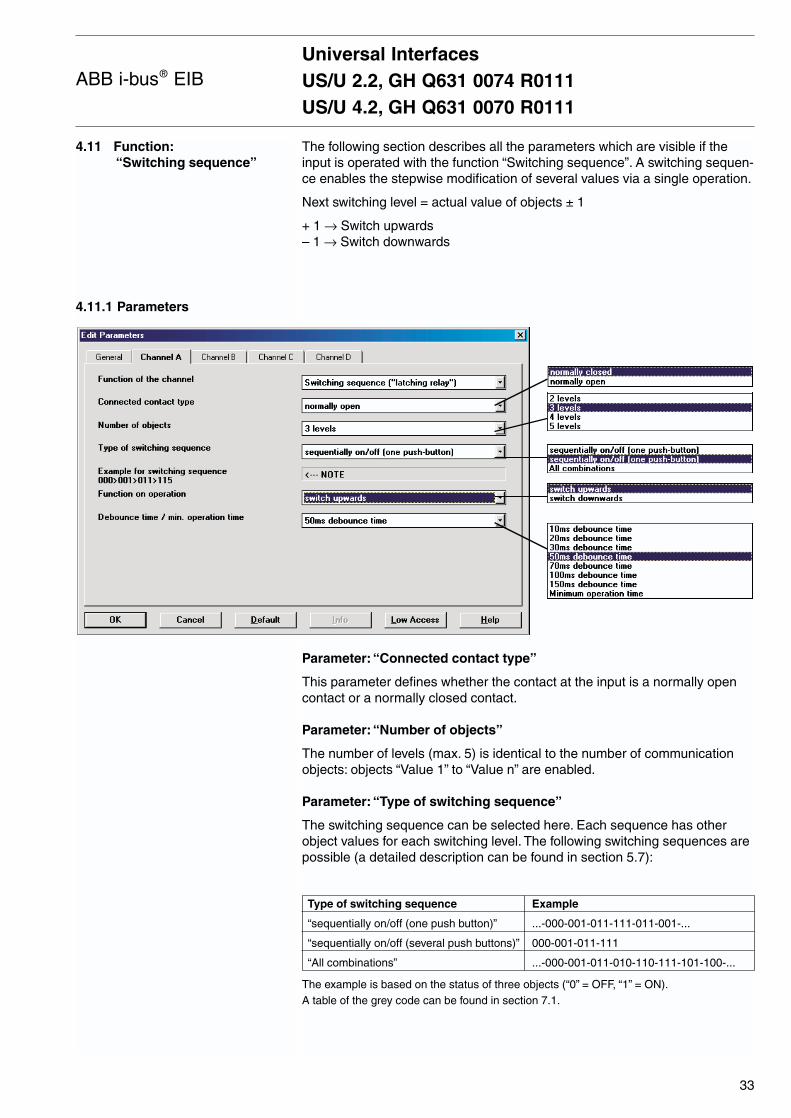
The following section describes all the parameters which are visible if theinput is operated with the function “Switching sequence”. A switching sequen-ce enables the stepwise modification of several values via a single operation.
Next switching level = actual value of objects ± 1
+ 1 → Switch upwards– 1 → Switch downwards
Parameter: “Connected contact type”
This parameter defines whether the contact at the input is a normally opencontact or a normally closed contact.
Parameter: “Number of objects”
The number of levels (max. 5) is identical to the number of communicationobjects: objects “Value 1” to “Value n” are enabled.
Parameter: “Type of switching sequence”
The switching sequence can be selected here. Each sequence has otherobject values for each switching level. The following switching sequences arepossible (a detailed description can be found in section 5.7):
Type of switching sequence Example
“sequentially on/off (one push button)” ...-000-001-011-111-011-001-...
“sequentially on/off (several push buttons)” 000-001-011-111
“All combinations” ...-000-001-011-010-110-111-101-100-...
The example is based on the status of three objects (“0” = OFF, “1” = ON).A table of the grey code can be found in section 7.1.
Universal InterfacesUS/U 2.2, GH Q631 0074 R0111US/U 4.2, GH Q631 0070 R0111
33
ABB i-bus® EIB
Parameter: “Function on operation”
Only visible in the switching sequence “sequentially on/off (several pushbuttons)”. It can be set whether an operation of the push button switches up or down a level.
Parameter: “Debounce time / min. operation time”
The debounce prevents unwanted multiple operation of the input e.g. bybouncing of the contacts. Refer to section 5.1 for the exact function of thisparameter.
Objects: “Telegr. value 1” to “Telegr. value 5”, 1 bit (EIS 1)
The number of these objects (max. 5) is set in the parameter “Number ofobjects”. The objects represent the values within a switching sequence.
Object: “Level increment/decrement”, 1 bit (EIS 1)
On receipt of an ON telegram at this communication object, the input swit-ches up one level in the switching sequence. On receipt of an OFF telegram,it switches down one level.
Telegram value: “0” Switch up one level“1” Switch down one level
4.11.2 Communication objects
Universal InterfacesUS/U 2.2, GH Q631 0074 R0111US/U 4.2, GH Q631 0070 R0111
34
ABB i-bus® EIB
4.12 Function: “Push buttonwith multiple operation”
4.12.1 Parameters
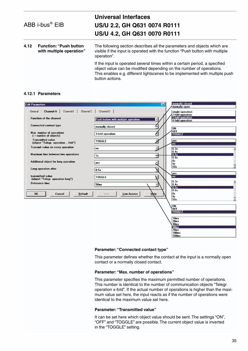
The following section describes all the parameters and objects which arevisible if the input is operated with the function “Push button with multipleoperation”.
If the input is operated several times within a certain period, a specifiedobject value can be modified depending on the number of operations.This enables e.g. different lightscenes to be implemented with multiple pushbutton actions.
Parameter: “Connected contact type”
This parameter defines whether the contact at the input is a normally opencontact or a normally closed contact.
Parameter: “Max. number of operations”
This parameter specifies the maximum permitted number of operations.This number is identical to the number of communication objects “Telegr.operation x-fold”. If the actual number of operations is higher than the maxi-mum value set here, the input reacts as if the number of operations wereidentical to the maximum value set here.
Parameter: “Transmitted value”
It can be set here which object value should be sent. The settings “ON”,“OFF” and “TOGGLE” are possible. The current object value is inverted in the “TOGGLE” setting.
Universal InterfacesUS/U 2.2, GH Q631 0074 R0111US/U 4.2, GH Q631 0070 R0111
35
ABB i-bus® EIB

Parameter: “Transmit value on each operation”
If “yes” is entered in this parameter, the associated object value is updatedand sent after each operation in the case of multiple push button actions.
Example: For three-fold operations, the objects “Telegr. operation 1-fold”(after the first operation), “Telegr. operation 2-fold” (after the second operati-on) and “Telegr. operation 3-fold” (after the third operation) are sent.
Parameter: “Maximum time between two operations”
This parameter sets the interval between two operations. After an operation,there is a delay for the duration specified here. If there are no further operati-ons within this period, the object “Telegr. switch” is sent and the period restarts after the next operation.
Parameter: “Additional object for long operation”
After a long operation of the input, a further function can be executed via theobject “Telegr. switch-long”. If a long operation is carried out after one orseveral short operations within the maximum period, the short operations are ignored.
Parameter: “Long operation after”
The period is defined here, after which an operation is interpreted as “long”.
Parameter: “Transmitted value”
It can be set here whether the object value “Telegr. switch-long” should beswitched on, switched off or toggled after a long operation.
Parameter: “Debounce time / min. operation time”
The debounce prevents unwanted multiple operation of the input e.g. bybouncing of the contacts. Refer to section 5.1 for the exact function of thisparameter. A minimum operation time can only be set when there is no distinction between a short and a long operation.
Objects: “Telegr. operation 1-fold” to “Telegr. operation 4-fold”,1 bit (EIS 1)
The number of these objects (max. 4) is set in the parameter “Max. number of operations”.
After multiple operation of an input, the corresponding object is sent according to the number of operations. The telegram value can be set in the parameters.
Object: “Telegr. operation-long”, 1 bit (EIS 1)
This object is visible if the value “yes” has been set in the parameter “Additional object for long operation”.
This object is sent once a long operation has been detected. The telegramvalue can be set in the parameters.
4.12.2 Communication objects
Universal InterfacesUS/U 2.2, GH Q631 0074 R0111US/U 4.2, GH Q631 0070 R0111
36
ABB i-bus® EIB

4.13 Function: “Counter”
4.13.1 Parameter
The following section describes all the parameters and objects which arevisible when the input is operated with the function “Counter”.
Using the “Counter” function, the device is able to count the number of pulseedges at the input. A “differential counter” is therefore available if required inaddition to the standard counter. Both counters are triggered by countingpulses but otherwise operate independently of each other. The counter always has the same data width as the differential counter.
Additional parameter window if “Enable additional options (…)” is set to “yes”.
Universal InterfacesUS/U 2.2, GH Q631 0074 R0111US/U 4.2, GH Q631 0070 R0111
37
ABB i-bus® EIB
Parameter: “Pulse detection on”
The type of input signal is defined in this parameter. It can be set whether the contact is a normally open contact or a normally closed contact.
Parameter: “Data width of counter”
The data type of the counter (absolute counter and differential counter) is defined in this parameter. The data type specifies the counting range forthe counter.
The type of the objects “Telegr. counter value …” and “Differential counter …”is adapted to the data width.
Parameter: “Counter starts at …”
The starting value of the absolute counter is defined in this parameter.The starting value is used when there is a counter overflow in order to calculate the new counter value.
Parameter: “Debounce time / min. operation time”
The debounce prevents unwanted multiple operation of the input e.g. bybouncing of the contacts. Refer to section 5.1 for the exact function of thisparameter.
Parameter: “Transmit counter values after bus voltage recovery”
If this parameter has the value “yes”, the current value of the counter is senton the bus after bus voltage recovery (once the transmission delay has elap-sed). If the differential counter has been enabled, it is also sent on the bus.
After an extended bus voltage failure, the counter is reset to the startingvalue. If the differential counter has been enabled, it is reset to zero. If nodata loss has occurred after a short bus voltage failure, the counter contentsare retained.
Parameter: “Enable additional options (…)”
If this parameter is set to “yes”, the parameter window “A-Counter” is display-ed. Additional functions are possible here.
Parameter window: “A-Counter”
Additional functions can be activated in this parameter window for the pulsecounter.
Parameter: “Divider: number of input pulses for one counter step”
It can be set via this parameter how many pulses are necessary to generatea counting pulse. It thus functions as a divider.
Parameter: “Factor: one counter step changes counter value by”
This parameter defines how much the counter and differential counter shouldbe increased by in the event of a counting pulse. It thus functions as a factor.
Parameter: “Transmit counter values cyclically”
If this parameter has the value “yes”, the values of the counter and the diffe-rential counter are sent cyclically on the bus.
Universal InterfacesUS/U 2.2, GH Q631 0074 R0111US/U 4.2, GH Q631 0070 R0111
38
ABB i-bus® EIB

4.13.2 Communication objects
Parameter: “Counter values are being transmitted every”
This parameter is visible if the parameter “Transmit counter values cyclically”has been set to “yes”. It can be set in which intervals the values are sentcyclically on the bus.
Parameter: “Enable differential counter”
The object “Differential counter” is made visible via this parameter.The differential counter can e.g. take over the function of a daily counter.
Parameter: “Over-/underrun of differential counter at”
This parameter is visible if the parameter “Enable differential counter”is set to “yes”.
It can be set in this parameter which value generates an overflow of thedifferential counter. In the event of an overflow, the same rules apply as forthe standard counter. The object “Differential counter overflow” is sentin this case.
Object: “Telegr. counter value … bytes”, 1 to 4 bytes
This object contains the absolute counter content of the pulse counter.The counter can have a data width of 1 byte, 2 bytes and 4 bytes.
The following table provides an overview of the data types:
Data width EIS type Value range
1 byte EIS 14 0...255
2 bytes EIS 10 -32.768...32.767
2 bytes EIS 10 0...65.535
4 bytes EIS 11 -2.147.483.648...2.147.483.647
Object: “Differential counter … bytes”, 1 to 4 bytes
This object is visible if the value “yes” has been set in the parameter “Enable differential counter”.
The object contains the status of the differential counter which is identical to the absolute counter in its counting function. In contrast to this counterhowever, it can be reset (object “Reset differential counter”) and a counteroverflow can be reported on the bus (object “Differential counter overflow”).Daily consumption values for example can be measured via the differentialcounter.
As soon as the differential counter reaches, exceeds or falls below the over-flow value defined in the parameter “Over-/underrun of differential counter at”,the overflow value is deducted from the value of the differential counter.
Object: “Request counter values”, 1 bit (EIS 1)
The values of the absolute counter and the differential counter are requestedvia this object.
Telegram value: “0” No reaction“1” Send counter values
Universal InterfacesUS/U 2.2, GH Q631 0074 R0111US/U 4.2, GH Q631 0070 R0111
39
ABB i-bus® EIB

Object: “Differential counter overflow”, 1 bit (EIS 1)
This object is visible if the value “yes” has been selected in the parameter“Enable differential counter”.
As soon as the value of the differential counter has exceeded or fallen belowthe overflow value defined in the parameter “Over-/underrun of differentialcounter at”, the object is sent on the bus (telegram value = “1”).
Object: “Reset differential counter”, 1 bit (EIS 1)
This object is visible if the value “yes” has been set in the parameter “Enable differential counter”. The differential counter can be reset to the value“0” via this object.
Telegram value: “0” No reaction“1” Reset differential counter
The device can be programmed via the EIB Tool Software ETS2 V1.2a orhigher. To reduce the programming time of the device via ETS, it is suppliedas pre-programmed. During the programming, it is automatically detectedwhether the device already has the correct application program.
If the device has been pre-programmed with another version, which shouldonly happen in exceptional cases, a full download is required. This can takeseveral minutes.
Note: If a programmed application program needs to be reprogrammed, the device must first be unloaded via the ETS.This can be necessary in rare cases e.g. if an error occurs during a download.
Important: If a device has no function after programming, please make a new product import of the Universal Interface (.VD2-file) into the ETS and repeat the programming.
4.14 Programming
Universal InterfacesUS/U 2.2, GH Q631 0074 R0111US/U 4.2, GH Q631 0070 R0111
40
ABB i-bus® EIB

5 Special functions
5.1 Debounce time and minimum operation time
The following section outlines special functions which could not be describedin connection with the parameters and objects due to lack of space.
A debounce time or a minimum operation time can be defined for each input.
Debounce timeIf a pulse edge is detected at the input, the input reacts to it immediately (e.g. with the sending of a telegram). The debounce time TD starts at thesame time. During the debounce time, the signal is not evaluated at the input.
The following example clarifies this:
When a pulse edge is detected at the input, further pulse edges are ignoredfor the duration of the debounce time TD.
Minimum operation timeThis function differs from the debounce time in that the telegram is only sentonce the minimum operation time has elapsed. The function operates asfollows:
If a pulse edge is detected at the input, the minimum operation time starts.No telegrams are sent on the bus at this point. The signal at the input isobserved during the minimum operation time. If a further pulse edge occursat the input during this period, it is interpreted as a new operation and theminimum operation time is restarted. If the input signal does not changeduring the minimum operation time, a pulse edge is detected and a telegramis likewise sent on the bus.
The following example clarifies this:
Since only two pulse edges remain stable for the duration of the minimumoperation time TM, only these edges are recognised as valid.
Universal InterfacesUS/U 2.2, GH Q631 0074 R0111US/U 4.2, GH Q631 0070 R0111
41
ABB i-bus® EIB
TD TD TD
Input signal
Detected pulse edge
TM TM
Input signal
Detected pulse edge
A new monitoring period starts at the end of the previous monitoring periodor – in the case of bus voltage recovery – at the end of the transmissiondelay. The transmitted telegrams are counted. As soon as the “Max. number of transmitted telegrams within a period” has been reached, no further tele-grams are sent on the bus until the end of the monitoring period. When a newmonitoring period starts, the telegram counter is reset to zero and the sen-ding of telegrams is again permitted.
Cyclical sending is part of the “Switch sensor” function. It enables the object“Telegr. switch” to be sent automatically at fixed intervals.
If cyclical sending is only carried out for a specific object value (ON or OFF),this condition is based on the value of the communication object. It is there-fore possible in principle to start the cyclical sending by sending a value tothe object “Telegr. switch”. Since this is generally not required, the “Write”and “Update” flags of the object are deleted in the default setting so that theobject cannot be modified via the bus. If this functionality should however berequired, these flags must be set accordingly.
When the object “Telegr. switch” is modified and after bus voltage recovery(once the transmission delay has elapsed), the object value is immediatelysent on the bus and the transmission cycle time is restarted. The minimumvalue for the cyclic period is 200 ms. If a smaller value is set in the parame-ters, the transmission cycle time is identical to the minimum value.
The option “1 push button dimming” is selected as the default setting i.e.the switching and dimming function can be fully controlled via a single pushbutton. As a result, a telegram for dimming BRIGHTER or DARKER is sentalternately after each dimming operation. If the object “Telegr. switch” = 0, a dimming BRIGHTER telegram is sent.To be able to evaluate the status signalof the actuator, the “Write” flag of the “Telegr. switch” object must be set.
5.2 Limit telegram rate
5.3 Cyclical sending
5.4 Dimming
Universal InterfacesUS/U 2.2, GH Q631 0074 R0111US/U 4.2, GH Q631 0070 R0111
42
ABB i-bus® EIB
5.5 Scene control
5.6 Control of electronic relay(heating actuator)
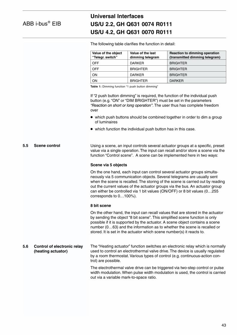
The following table clarifies the function in detail:
Value of the object Value of the last Reaction to dimming operation “Telegr. switch” dimming telegram (transmitted dimming telegram)
OFF DARKER BRIGHTER
OFF BRIGHTER BRIGHTER
ON DARKER BRIGHTER
ON BRIGHTER DARKER
Table 1: Dimming function “1 push button dimming”
If “2 push button dimming” is required, the function of the individual pushbutton (e.g. “ON” or “DIM BRIGHTER”) must be set in the parameters “Reaction on short or long operation”. The user thus has complete freedomover
which push buttons should be combined together in order to dim a groupof luminaires
which function the individual push button has in this case.
Using a scene, an input controls several actuator groups at a specific, presetvalue via a single operation. The input can recall and/or store a scene via thefunction “Control scene”. A scene can be implemented here in two ways:
Scene via 5 objects
On the one hand, each input can control several actuator groups simulta-neously via 5 communication objects. Several telegrams are usually sentwhen the scene is recalled. The storing of the scene is carried out by readingout the current values of the actuator groups via the bus. An actuator groupcan either be controlled via 1 bit values (ON/OFF) or 8 bit values (0…255corresponds to 0…100%).
8 bit scene
On the other hand, the input can recall values that are stored in the actuatorby sending the object “8 bit scene”. This simplified scene function is onlypossible if it is supported by the actuator. A scene object contains a scenenumber (0…63) and the information as to whether the scene is recalled orstored. It is set in the actuator which scene number(s) it reacts to.
The “Heating actuator” function switches an electronic relay which is normallyused to control an electrothermal valve drive. The device is usually regulatedby a room thermostat. Various types of control (e.g. continuous-action con-trol) are possible.
The electrothermal valve drive can be triggered via two-step control or pulsewidth modulation. When pulse width modulation is used, the control is carriedout via a variable mark-to-space ratio.
Universal InterfacesUS/U 2.2, GH Q631 0074 R0111US/U 4.2, GH Q631 0070 R0111
43
ABB i-bus® EIB

The following example clarifies this:
During tON, the valve is triggered with OPEN (“ON phase”). During tOFF, the valve is triggered with CLOSE (“OFF phase”). Due to tON = 0.4 x TCYC,the valve is set at approx. 40%. TCYC is the so-called PWM cycle time forcontinuous control.
The actuator can trigger specific special positions during “Forced positio-ning”, “Valve purge” and “Safety position”. The following diagram provides an overview:
Universal InterfacesUS/U 2.2, GH Q631 0074 R0111US/U 4.2, GH Q631 0070 R0111
44
ABB i-bus® EIB
T
t0%
100%
40%
tON tOFF
CYC
Start
Is forcedpositioning
active?
Trigger forcedpositioning
yes
Valve opened tomaximum for
duration of valvepurge
no
yes
Trigger safetyposition
yes
no
Type ofcontrol
Control acc. toobject “Controlvalue (PWM)”
Output followsobject “Telegr.
switch”
no
8 bit1 bit
Is valvepurge
active?
Is faultmode
active?
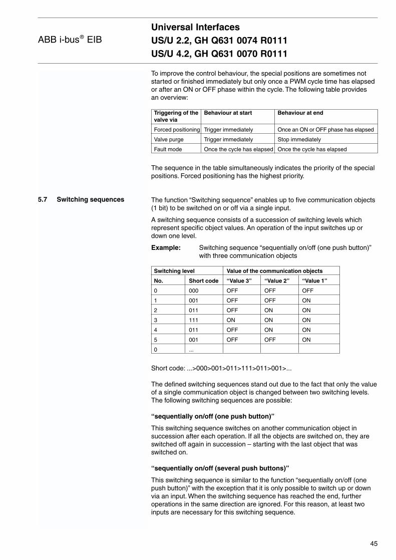
5.7 Switching sequences
To improve the control behaviour, the special positions are sometimes notstarted or finished immediately but only once a PWM cycle time has elapsedor after an ON or OFF phase within the cycle. The following table provides an overview:
Triggering of the Behaviour at start Behaviour at endvalve via
Forced positioning Trigger immediately Once an ON or OFF phase has elapsed
Valve purge Trigger immediately Stop immediately
Fault mode Once the cycle has elapsed Once the cycle has elapsed
The sequence in the table simultaneously indicates the priority of the specialpositions. Forced positioning has the highest priority.
The function “Switching sequence” enables up to five communication objects(1 bit) to be switched on or off via a single input.
A switching sequence consists of a succession of switching levels whichrepresent specific object values. An operation of the input switches up ordown one level.
Example: Switching sequence “sequentially on/off (one push button)”with three communication objects
Switching level Value of the communication objects
No. Short code “Value 3” “Value 2” “Value 1”
0 000 OFF OFF OFF
1 001 OFF OFF ON
2 011 OFF ON ON
3 111 ON ON ON
4 011 OFF ON ON
5 001 OFF OFF ON
0 ...
Short code: ...>000>001>011>111>011>001>...
The defined switching sequences stand out due to the fact that only the valueof a single communication object is changed between two switching levels.The following switching sequences are possible:
“sequentially on/off (one push button)”
This switching sequence switches on another communication object in succession after each operation. If all the objects are switched on, they areswitched off again in succession – starting with the last object that was switched on.
“sequentially on/off (several push buttons)”
This switching sequence is similar to the function “sequentially on/off (onepush button)” with the exception that it is only possible to switch up or downvia an input. When the switching sequence has reached the end, furtheroperations in the same direction are ignored. For this reason, at least twoinputs are necessary for this switching sequence.
Universal InterfacesUS/U 2.2, GH Q631 0074 R0111US/U 4.2, GH Q631 0070 R0111
45
ABB i-bus® EIB
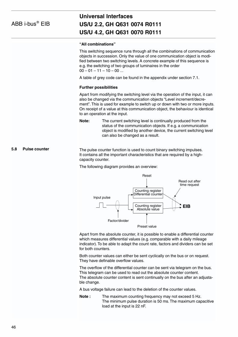
“All combinations”
This switching sequence runs through all the combinations of communicationobjects in succession. Only the value of one communication object is modi-fied between two switching levels. A concrete example of this sequence ise.g. the switching of two groups of luminaires in the order 00 – 01 – 11 – 10 – 00 ...
A table of grey code can be found in the appendix under section 7.1.
Further possibilities
Apart from modifying the switching level via the operation of the input, it canalso be changed via the communication objects “Level increment/decre-ment”. This is used for example to switch up or down with two or more inputs.On receipt of a value at this communication object, the behaviour is identicalto an operation at the input.
Note: The current switching level is continually produced from thestatus of the communication objects. If e.g. a communicationobject is modified by another device, the current switching levelcan also be changed as a result.
The pulse counter function is used to count binary switching impulses.It contains all the important characteristics that are required by a high-capacity counter.
The following diagram provides an overview:
Apart from the absolute counter, it is possible to enable a differential counterwhich measures differential values (e.g. comparable with a daily mileageindicator). To be able to adapt the count rate, factors and dividers can be setfor both counters.
Both counter values can either be sent cyclically on the bus or on request.They have definable overflow values.
The overflow of the differential counter can be sent via telegram on the bus.This telegram can be used to read out the absolute counter content.The absolute counter content is sent continually on the bus after an adjusta-ble change.
A bus voltage failure can lead to the deletion of the counter values.
Note : The maximum counting frequency may not exceed 5 Hz.The minimum pulse duration is 50 ms. The maximum capacitiveload at the input is 22 nF.
5.8 Pulse counter
Universal InterfacesUS/U 2.2, GH Q631 0074 R0111US/U 4.2, GH Q631 0070 R0111
46
ABB i-bus® EIB
Counting registerDifferential counter
Counting registerAbsolute value
Factor/divider
Preset value
Reset
EIB
Read out aftertime request
Input pulse
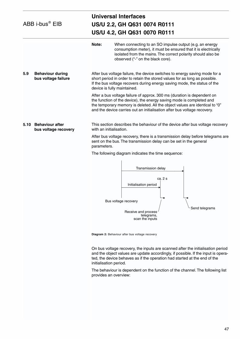
5.9 Behaviour during bus voltage failure
5.10 Behaviour after bus voltage recovery
Note: When connecting to an SO impulse output (e.g. an energyconsumption meter), it must be ensured that it is electricallyisolated from the mains. The correct polarity should also beobserved (“-” on the black core).
After bus voltage failure, the device switches to energy saving mode for ashort period in order to retain the stored values for as long as possible.If the bus voltage recovers during energy saving mode, the status of thedevice is fully maintained.
After a bus voltage failure of approx. 300 ms (duration is dependent on the function of the device), the energy saving mode is completed and the temporary memory is deleted. All the object values are identical to “0”and the device carries out an initialisation after bus voltage recovery.
This section describes the behaviour of the device after bus voltage recoverywith an initialisation.
After bus voltage recovery, there is a transmission delay before telegrams aresent on the bus. The transmission delay can be set in the generalparameters.
The following diagram indicates the time sequence:
Diagram 2: Behaviour after bus voltage recovery
On bus voltage recovery, the inputs are scanned after the initialisation periodand the object values are update accordingly, if possible. If the input is opera-ted, the device behaves as if the operation had started at the end of theinitialisation period.
The behaviour is dependent on the function of the channel. The following listprovides an overview:
Universal InterfacesUS/U 2.2, GH Q631 0074 R0111US/U 4.2, GH Q631 0070 R0111
47
ABB i-bus® EIB
Bus voltage recovery
ca. 2 s
Transmission delay
Send telegrams
Initialisation period
Receive and processtelegrams,
scan the inputs
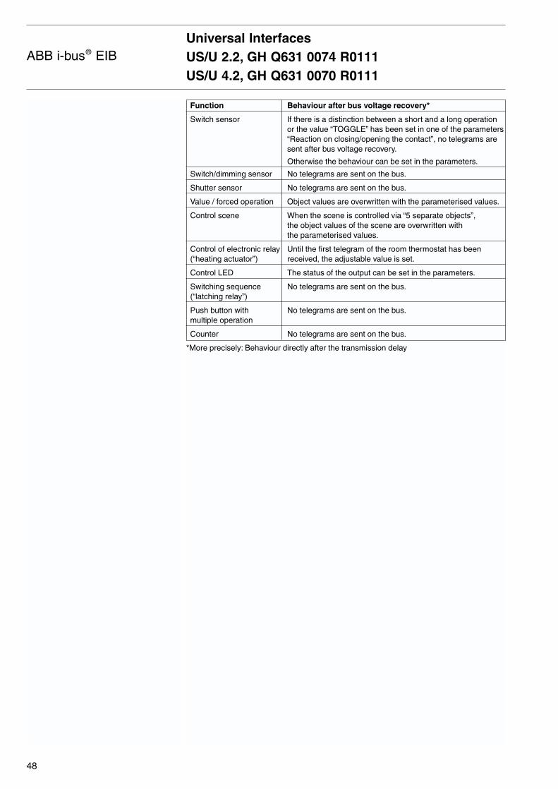
Function Behaviour after bus voltage recovery*
Switch sensor If there is a distinction between a short and a long operationor the value “TOGGLE” has been set in one of the parameters“Reaction on closing/opening the contact”, no telegrams aresent after bus voltage recovery.
Otherwise the behaviour can be set in the parameters.
Switch/dimming sensor No telegrams are sent on the bus.
Shutter sensor No telegrams are sent on the bus.
Value / forced operation Object values are overwritten with the parameterised values.
Control scene When the scene is controlled via “5 separate objects”, the object values of the scene are overwritten with the parameterised values.
Control of electronic relay Until the first telegram of the room thermostat has been (“heating actuator”) received, the adjustable value is set.
Control LED The status of the output can be set in the parameters.
Switching sequence No telegrams are sent on the bus.(“latching relay”)
Push button with No telegrams are sent on the bus.multiple operation
Counter No telegrams are sent on the bus.
*More precisely: Behaviour directly after the transmission delay
Universal InterfacesUS/U 2.2, GH Q631 0074 R0111US/U 4.2, GH Q631 0070 R0111
48
ABB i-bus® EIB
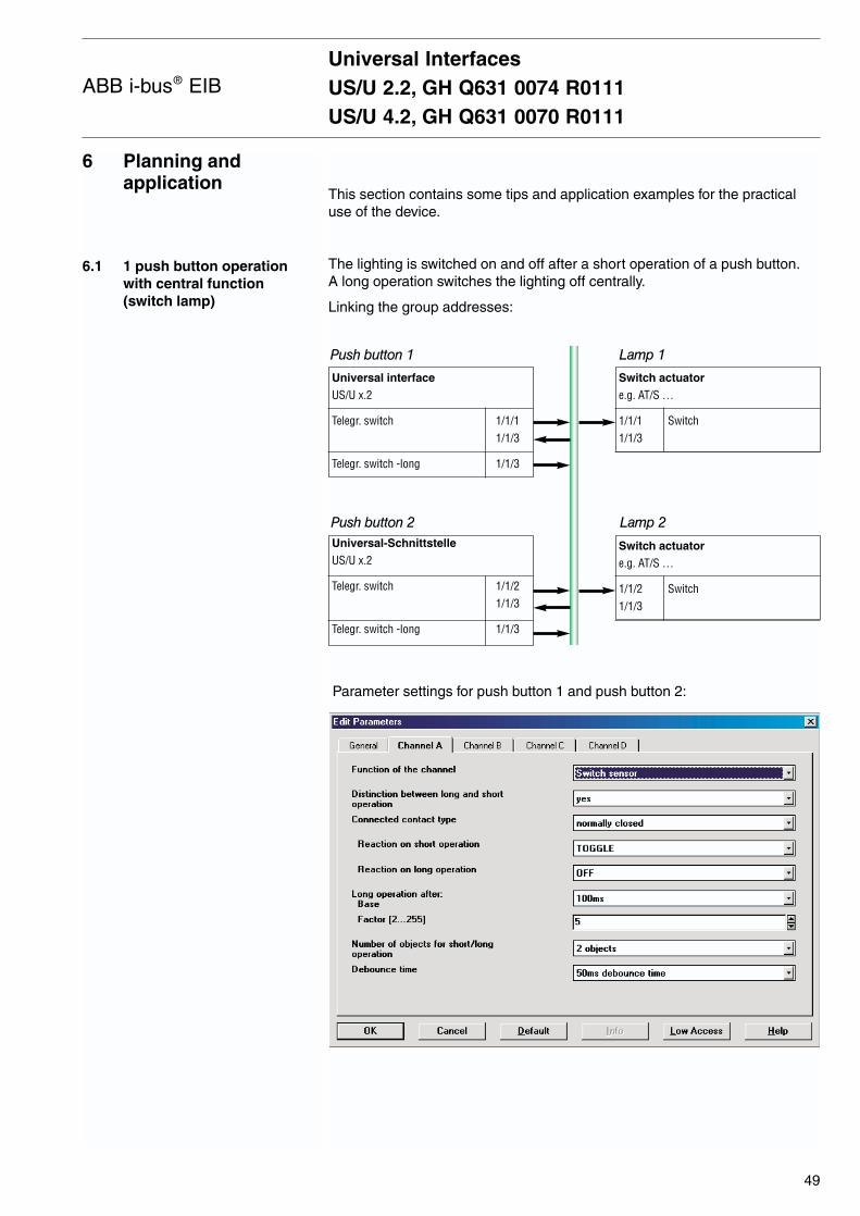
6 Planning and application
6.1 1 push button operationwith central function (switch lamp)
This section contains some tips and application examples for the practicaluse of the device.
The lighting is switched on and off after a short operation of a push button.A long operation switches the lighting off centrally.
Linking the group addresses:
Parameter settings for push button 1 and push button 2:
Universal InterfacesUS/U 2.2, GH Q631 0074 R0111US/U 4.2, GH Q631 0070 R0111
49
ABB i-bus® EIB
Universal interface
US/U x.2
Telegr. switch 1/1/11/1/3
Telegr. switch -long 1/1/3
Switch actuator
e.g. AT/S …
1/1/1 Switch1/1/3
Universal-Schnittstelle
US/U x.2
Telegr. switch 1/1/21/1/3
Telegr. switch -long 1/1/3
Switch actuator
e.g. AT/S …
1/1/2 Switch1/1/3
Push button 1 Lamp 1
Push button 2 Lamp 2
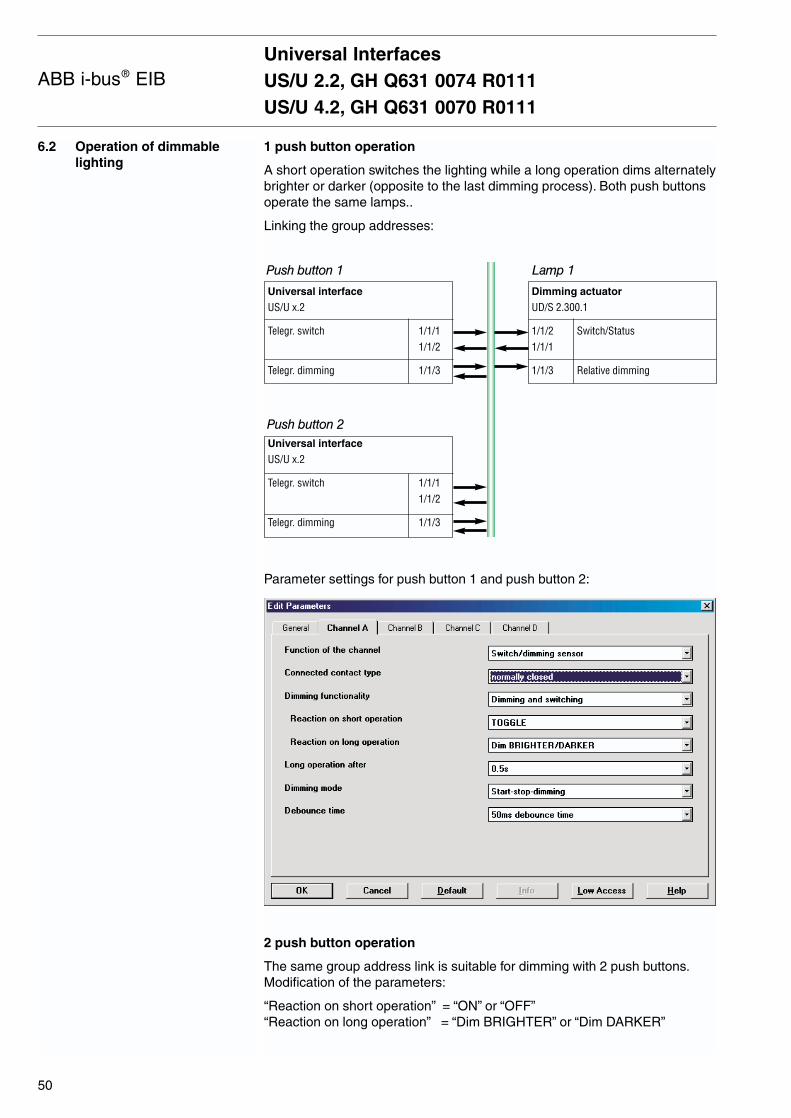
Universal InterfacesUS/U 2.2, GH Q631 0074 R0111US/U 4.2, GH Q631 0070 R0111
50
ABB i-bus® EIB
6.2 Operation of dimmablelighting
1 push button operation
A short operation switches the lighting while a long operation dims alternatelybrighter or darker (opposite to the last dimming process). Both push buttonsoperate the same lamps..
Linking the group addresses:
Parameter settings for push button 1 and push button 2:
2 push button operation
The same group address link is suitable for dimming with 2 push buttons.Modification of the parameters:
“Reaction on short operation” = “ON” or “OFF”“Reaction on long operation” = “Dim BRIGHTER” or “Dim DARKER”
Universal interface
US/U x.2
Telegr. switch 1/1/11/1/2
Telegr. dimming 1/1/3
Dimming actuator
UD/S 2.300.1
1/1/2 Switch/Status1/1/1
1/1/3 Relative dimming
Universal interface
US/U x.2
Telegr. switch 1/1/11/1/2
Telegr. dimming 1/1/3
Push button 1 Lamp 1
Push button 2
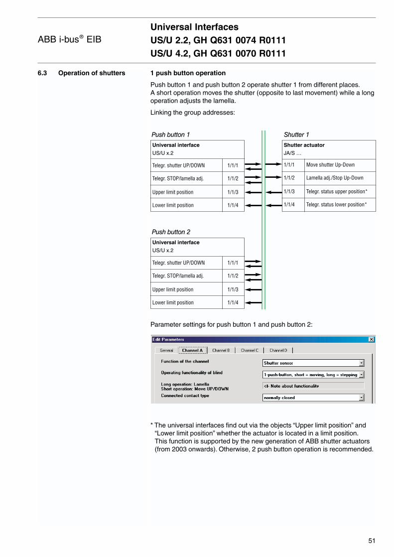
6.3 Operation of shutters 1 push button operation
Push button 1 and push button 2 operate shutter 1 from different places.A short operation moves the shutter (opposite to last movement) while a longoperation adjusts the lamella.
Linking the group addresses:
Parameter settings for push button 1 and push button 2:
* The universal interfaces find out via the objects “Upper limit position” and“Lower limit position” whether the actuator is located in a limit position.This function is supported by the new generation of ABB shutter actuators(from 2003 onwards). Otherwise, 2 push button operation is recommended.
Universal InterfacesUS/U 2.2, GH Q631 0074 R0111US/U 4.2, GH Q631 0070 R0111
51
ABB i-bus® EIB
Universal interface
US/U x.2
Telegr. shutter UP/DOWN 1/1/1
Telegr. STOP/lamella adj. 1/1/2
Upper limit position 1/1/3
Lower limit position 1/1/4
Shutter actuator
JA/S …
1/1/1 Move shutter Up-Down
1/1/2 Lamella adj./Stop Up-Down
1/1/3 Telegr. status upper position*
1/1/4 Telegr. status lower position*
Push button 1 Shutter 1
Push button 2
Universal interface
US/U x.2
Telegr. shutter UP/DOWN 1/1/1
Telegr. STOP/lamella adj. 1/1/2
Upper limit position 1/1/3
Lower limit position 1/1/4
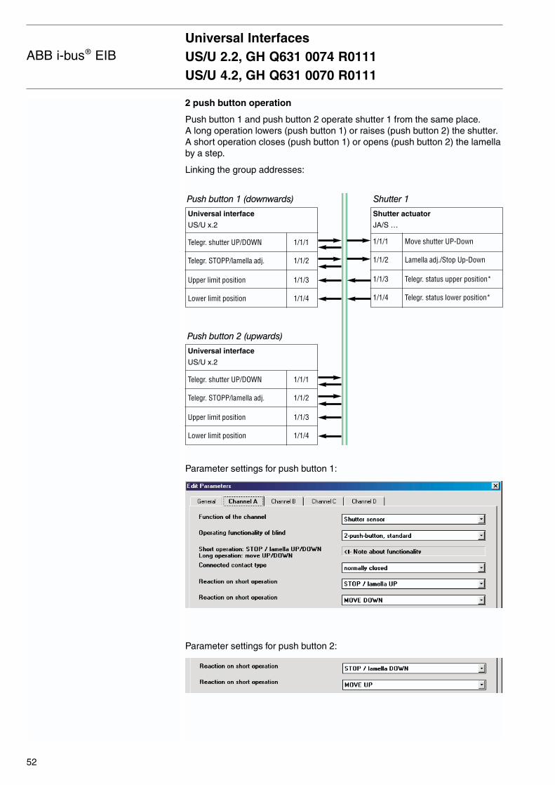
Universal InterfacesUS/U 2.2, GH Q631 0074 R0111US/U 4.2, GH Q631 0070 R0111
52
ABB i-bus® EIB
2 push button operation
Push button 1 and push button 2 operate shutter 1 from the same place.A long operation lowers (push button 1) or raises (push button 2) the shutter.A short operation closes (push button 1) or opens (push button 2) the lamellaby a step.
Linking the group addresses:
Parameter settings for push button 1:
Parameter settings for push button 2:
Universal interface
US/U x.2
Telegr. shutter UP/DOWN 1/1/1
Telegr. STOPP/lamella adj. 1/1/2
Upper limit position 1/1/3
Lower limit position 1/1/4
Shutter actuator
JA/S …
1/1/1 Move shutter UP-Down
1/1/2 Lamella adj./Stop Up-Down
1/1/3 Telegr. status upper position*
1/1/4 Telegr. status lower position*
Push button 1 (downwards) Shutter 1
Push button 2 (upwards)
Universal interface
US/U x.2
Telegr. shutter UP/DOWN 1/1/1
Telegr. STOPP/lamella adj. 1/1/2
Upper limit position 1/1/3
Lower limit position 1/1/4
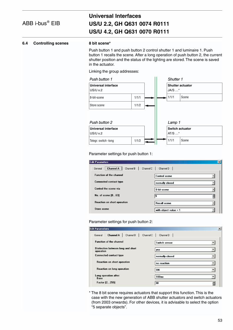
6.4 Controlling scenes 8 bit scene*
Push button 1 and push button 2 control shutter 1 and luminaire 1. Pushbutton 1 recalls the scene. After a long operation of push button 2, the currentshutter position and the status of the lighting are stored. The scene is savedin the actuator.
Linking the group addresses:
Parameter settings for push button 1:
Parameter settings for push button 2:
* The 8 bit scene requires actuators that support this function. This is thecase with the new generation of ABB shutter actuators and switch actuators(from 2003 onwards). For other devices, it is advisable to select the option“5 separate objects”.
Universal InterfacesUS/U 2.2, GH Q631 0074 R0111US/U 4.2, GH Q631 0070 R0111
53
ABB i-bus® EIB
Universal interface
US/U x.2
8-bit-scene 1/1/1
Store scene 1/1/2
Shutter actuator
JA/S …*
1/1/1 Scene
Push button 1 Shutter 1
Universal interface
US/U x.2
Telegr. switch -long 1/1/2
Switch actuator
AT/S …*
1/1/1 Scene
Push button 2 Lamp 1
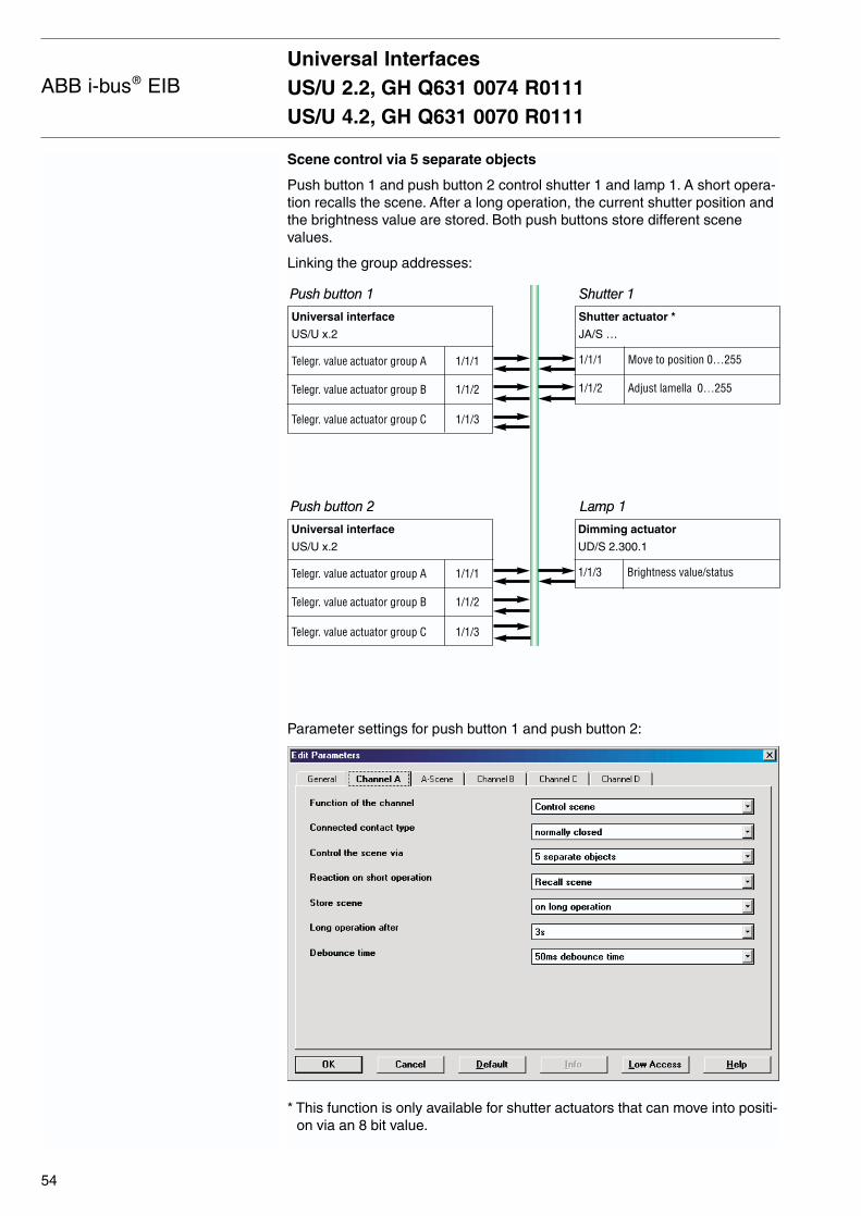
Scene control via 5 separate objects
Push button 1 and push button 2 control shutter 1 and lamp 1. A short opera-tion recalls the scene. After a long operation, the current shutter position andthe brightness value are stored. Both push buttons store different scenevalues.
Linking the group addresses:
Parameter settings for push button 1 and push button 2:
* This function is only available for shutter actuators that can move into positi-on via an 8 bit value.
Universal InterfacesUS/U 2.2, GH Q631 0074 R0111US/U 4.2, GH Q631 0070 R0111
54
ABB i-bus® EIB
Universal interface
US/U x.2
Telegr. value actuator group A 1/1/1
Telegr. value actuator group B 1/1/2
Telegr. value actuator group C 1/1/3
Shutter actuator *
JA/S …
1/1/1 Move to position 0…255
1/1/2 Adjust lamella 0…255
Dimming actuator
UD/S 2.300.1
1/1/3 Brightness value/status
Push button 1 Shutter 1
Push button 2 Lamp 1
Universal interface
US/U x.2
Telegr. value actuator group A 1/1/1
Telegr. value actuator group B 1/1/2
Telegr. value actuator group C 1/1/3
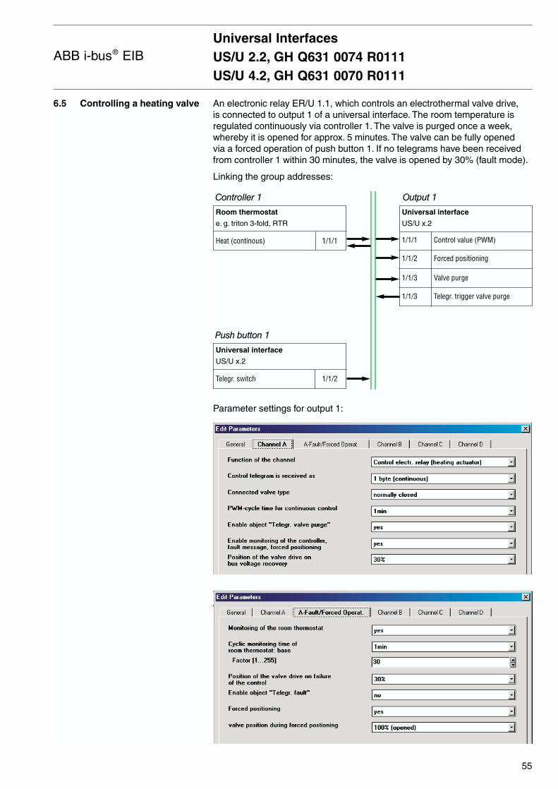
6.5 Controlling a heating valve An electronic relay ER/U 1.1, which controls an electrothermal valve drive, is connected to output 1 of a universal interface. The room temperature isregulated continuously via controller 1. The valve is purged once a week,whereby it is opened for approx. 5 minutes. The valve can be fully openedvia a forced operation of push button 1. If no telegrams have been receivedfrom controller 1 within 30 minutes, the valve is opened by 30% (fault mode).
Linking the group addresses:
Parameter settings for output 1:
Universal InterfacesUS/U 2.2, GH Q631 0074 R0111US/U 4.2, GH Q631 0070 R0111
55
ABB i-bus® EIB
Room thermostat
e. g. triton 3-fold, RTR
Heat (continous) 1/1/1
Universal interface
US/U x.2
1/1/1 Control value (PWM)
1/1/2 Forced positioning
1/1/3 Valve purge
1/1/3 Telegr. trigger valve purge
Controller 1 Output 1
Push button 1
Universal interface
US/U x.2
Telegr. switch 1/1/2

Output 1 sends itself the group address 1/1/3 once a week and therebytriggers the valve purge. The sending object is enabled in the “General”parameter window.
Universal InterfacesUS/U 2.2, GH Q631 0074 R0111US/U 4.2, GH Q631 0070 R0111
56
ABB i-bus® EIB

6.6 Switching the lighting in sequence
Sequentially on/off (several push buttons)
Push button 1 and push button 2 control a luminaire with three independentcircuits – lamp 1, lamp 2, lamp 3. Push button 1 switches them on in sequen-ce (order: lamp 1>lamp 2>lamp 3). Push button 2 switches them off in sequence (order: lamp 3>lamp 2>lamp 1).
Linking the group addresses:
Parameter settings for push button 1:
The parameters of push button 2 should be set so that “Telegr. switch” sendsa “0” with each push button action.
Universal InterfacesUS/U 2.2, GH Q631 0074 R0111US/U 4.2, GH Q631 0070 R0111
57
ABB i-bus® EIB
Universal interface
US/U x.2
Telegr. value 1 1/1/1
Telegr. value 2 1/1/2
Telegr. value 3 1/1/3
Level increment/decrement 1/1/4
Switch actuator
AT/S …
1/1/1 Switch
Switch actuator
AT/S …
1/1/3 Switch
Push button 1 Lamp 1
Push button 2
Switch actuator
AT/S …
1/1/2 Switch
Lamp 2
Lamp 3
Universal interface
US/U x.2
Telegr. switch 1/1/4
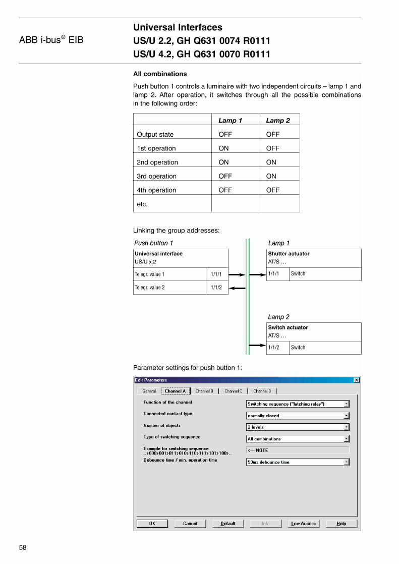
Universal InterfacesUS/U 2.2, GH Q631 0074 R0111US/U 4.2, GH Q631 0070 R0111
58
ABB i-bus® EIB
All combinations
Push button 1 controls a luminaire with two independent circuits – lamp 1 andlamp 2. After operation, it switches through all the possible combinations in the following order:
Lamp 1 Lamp 2
Output state OFF OFF
1st operation ON OFF
2nd operation ON ON
3rd operation OFF ON
4th operation OFF OFF
etc.
Linking the group addresses:
Parameter settings for push button 1:
Universal interface
US/U x.2
Telegr. value 1 1/1/1
Telegr. value 2 1/1/2
Shutter actuator
AT/S …
1/1/1 Switch
Push button 1 Lamp 1
Switch actuator
AT/S …
1/1/2 Switch
Lamp 2
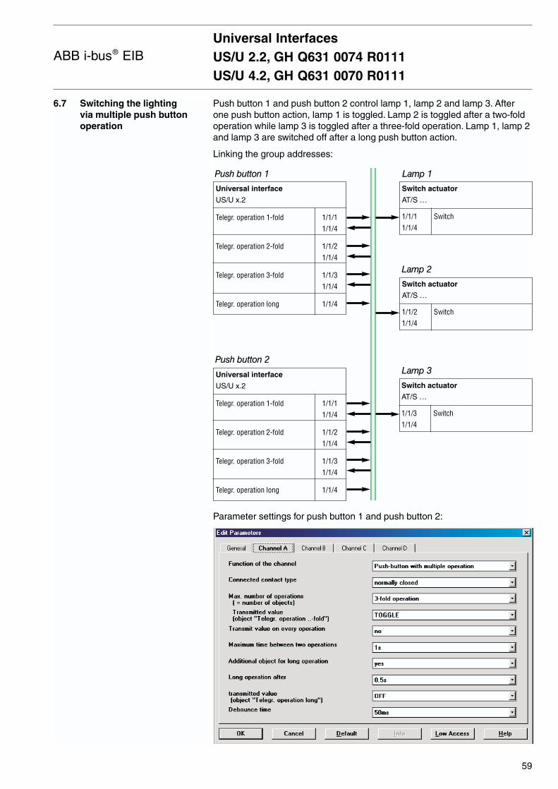
6.7 Switching the lighting via multiple push buttonoperation
Push button 1 and push button 2 control lamp 1, lamp 2 and lamp 3. Afterone push button action, lamp 1 is toggled. Lamp 2 is toggled after a two-foldoperation while lamp 3 is toggled after a three-fold operation. Lamp 1, lamp 2and lamp 3 are switched off after a long push button action.
Linking the group addresses:
Parameter settings for push button 1 and push button 2:
Universal InterfacesUS/U 2.2, GH Q631 0074 R0111US/U 4.2, GH Q631 0070 R0111
59
ABB i-bus® EIB
Universal interface
US/U x.2
Telegr. operation 1-fold 1/1/11/1/4
Telegr. operation 2-fold 1/1/21/1/4
Telegr. operation 3-fold 1/1/31/1/4
Telegr. operation long 1/1/4
Switch actuator
AT/S …
1/1/1 Switch1/1/4
Switch actuator
AT/S …
1/1/3 Switch1/1/4
Push button 1 Lamp 1
Push button 2
Universal interface
US/U x.2
Telegr. operation 1-fold 1/1/11/1/4
Telegr. operation 2-fold 1/1/21/1/4
Telegr. operation 3-fold 1/1/31/1/4
Telegr. operation long 1/1/4
Switch actuator
AT/S …
1/1/2 Switch1/1/4
Lamp 2
Lamp 3
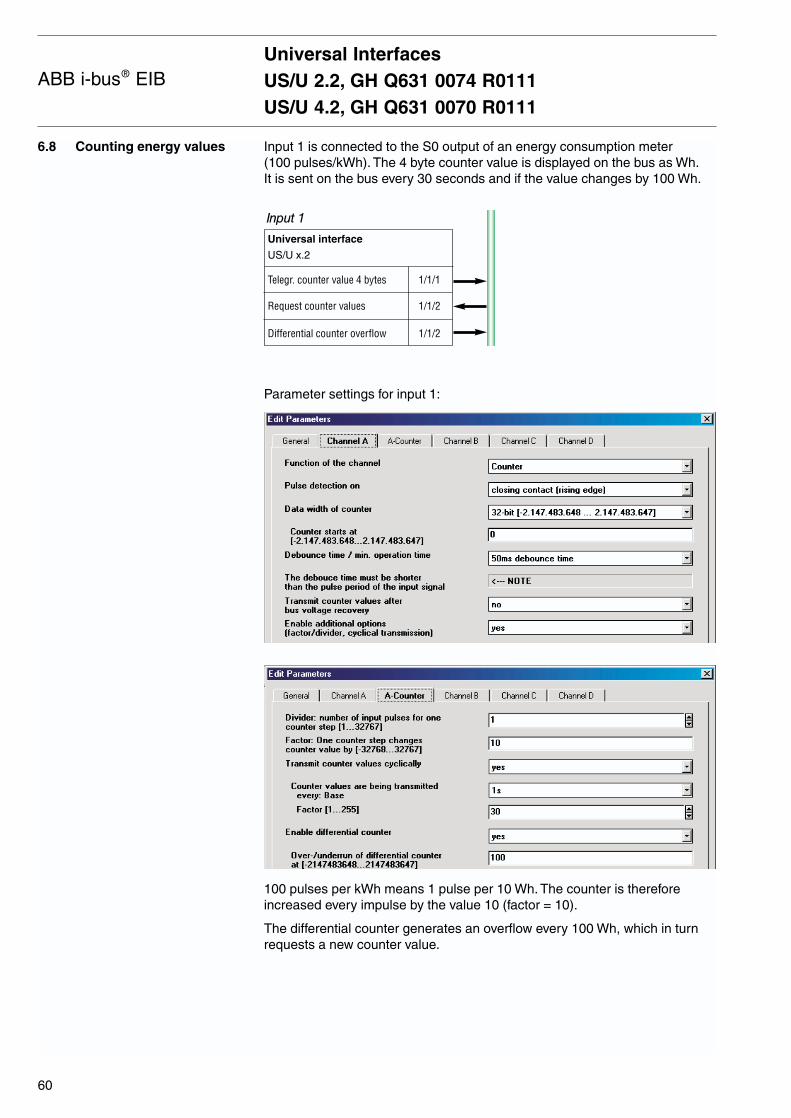
Universal InterfacesUS/U 2.2, GH Q631 0074 R0111US/U 4.2, GH Q631 0070 R0111
60
ABB i-bus® EIB
6.8 Counting energy values Input 1 is connected to the S0 output of an energy consumption meter (100 pulses/kWh). The 4 byte counter value is displayed on the bus as Wh.It is sent on the bus every 30 seconds and if the value changes by 100 Wh.
Parameter settings for input 1:
100 pulses per kWh means 1 pulse per 10 Wh. The counter is thereforeincreased every impulse by the value 10 (factor = 10).
The differential counter generates an overflow every 100 Wh, which in turnrequests a new counter value.
Universal interface
US/U x.2
Telegr. counter value 4 bytes 1/1/1
Request counter values 1/1/2
Differential counter overflow 1/1/2
Input 1
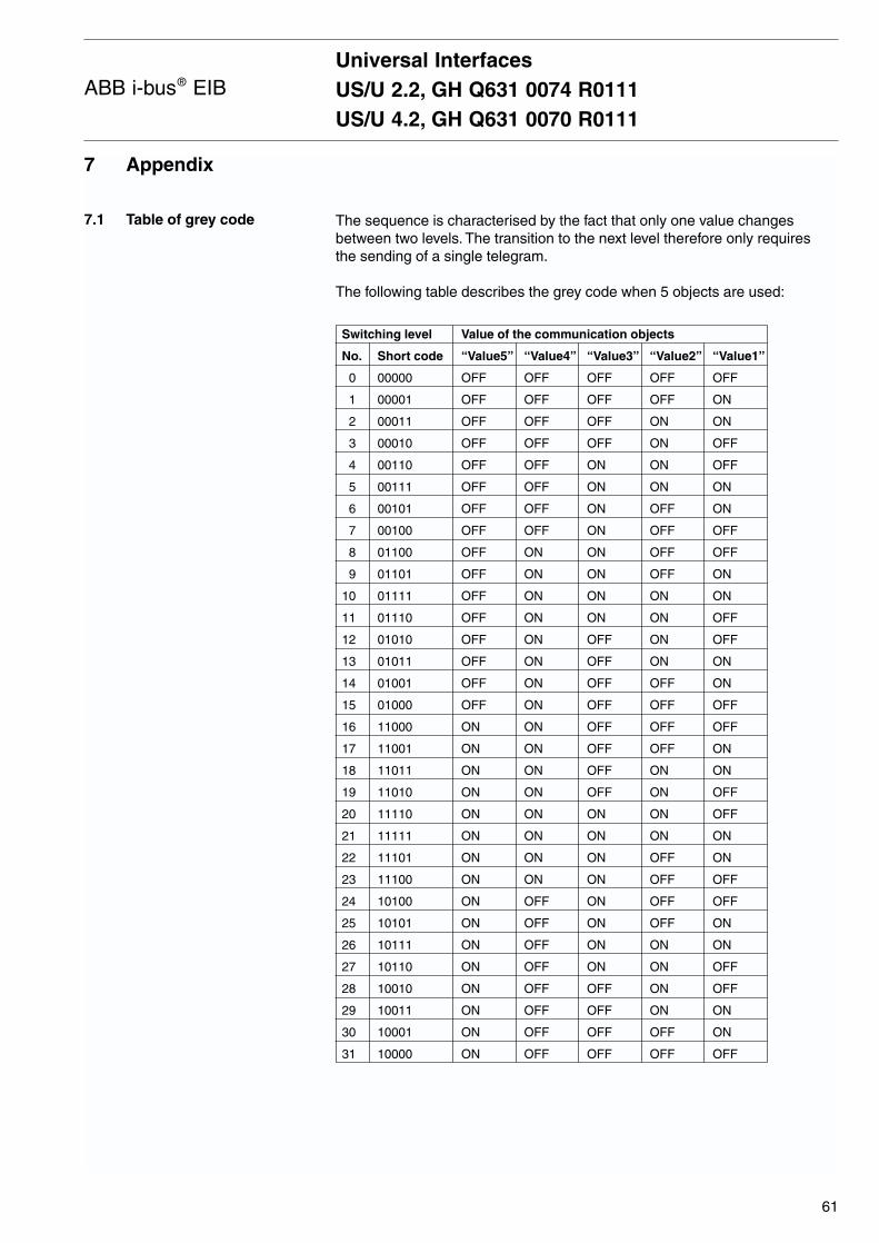
The sequence is characterised by the fact that only one value changes between two levels. The transition to the next level therefore only requires the sending of a single telegram.
The following table describes the grey code when 5 objects are used:
Switching level Value of the communication objects
No. Short code “Value5” “Value4” “Value3” “Value2” “Value1”
0 00000 OFF OFF OFF OFF OFF
1 00001 OFF OFF OFF OFF ON
2 00011 OFF OFF OFF ON ON
3 00010 OFF OFF OFF ON OFF
4 00110 OFF OFF ON ON OFF
5 00111 OFF OFF ON ON ON
6 00101 OFF OFF ON OFF ON
7 00100 OFF OFF ON OFF OFF
8 01100 OFF ON ON OFF OFF
9 01101 OFF ON ON OFF ON
10 01111 OFF ON ON ON ON
11 01110 OFF ON ON ON OFF
12 01010 OFF ON OFF ON OFF
13 01011 OFF ON OFF ON ON
14 01001 OFF ON OFF OFF ON
15 01000 OFF ON OFF OFF OFF
16 11000 ON ON OFF OFF OFF
17 11001 ON ON OFF OFF ON
18 11011 ON ON OFF ON ON
19 11010 ON ON OFF ON OFF
20 11110 ON ON ON ON OFF
21 11111 ON ON ON ON ON
22 11101 ON ON ON OFF ON
23 11100 ON ON ON OFF OFF
24 10100 ON OFF ON OFF OFF
25 10101 ON OFF ON OFF ON
26 10111 ON OFF ON ON ON
27 10110 ON OFF ON ON OFF
28 10010 ON OFF OFF ON OFF
29 10011 ON OFF OFF ON ON
30 10001 ON OFF OFF OFF ON
31 10000 ON OFF OFF OFF OFF
Universal InterfacesUS/U 2.2, GH Q631 0074 R0111US/U 4.2, GH Q631 0070 R0111
61
ABB i-bus® EIB
7 Appendix
7.1 Table of grey code

Universal InterfacesUS/U 2.2, GH Q631 0074 R0111US/U 4.2, GH Q631 0070 R0111
62
ABB i-bus® EIB
7.2 Ordering information
Description Ordering info. Product code bbn 40 16779 Unit price Price Weight Package Short code EAN [EURO] group 1 Pc. [kg] [Pc.]
Universal interface, US/U 2.2 GH Q631 0074 R0111 56483 0 26 0.05 12-fold
Universal interface, US/U 4.2 GH Q631 0070 R0111 56481 6 26 0.05 14-fold

63
Notizen

64
Notizen

The information in this leaflet is subject to change without further notice. Pub
No.
2CD
C 5
04 0
19 D
0201
Your EIB-Partner