
PRODUCT CATALOGUE FIRE PROTECTION
62
PRODUCT CATALOGUE FIRE PROTECTION A truly world class manufacturer serving Global Markets
Transcript of PRODUCT CATALOGUE FIRE PROTECTION

PRODUCT CATALOGUEFIRE PROTECTIONA truly world class manufacturer serving Global Markets

A True Manufacturer
Fivalco is a widely recognised world class manufacturer of flow control products primarily serving the critical Fire Protection, General Process Industries, Water Supply and Heating, Ventilating & Air Conditioning (HVAC) markets worldwide.
We operate from two main facilities utilising the latest manufacturing technologies and equipment available to produce world class flow control products serving multiple industries.
Our primary mission is to continue to provide the highest quality products to discerning customers, whilst allowing our employees career growth prospects, all elements working together as partners to enhance stakeholder value.

FIVALCO HIGHRISER OS&Y GATE VALVE
HIGH STRENGTH DUCTILEIRON BODY+BONNET
TRIPLE PTFE SEAL
FUSION BONDED EPOXY COATING
BRONZE STEM NUT
STAINLESS STEEL STEM
STAINLESS STEEL YOKE BOLTS
PRE GROOVED FOR TAMPER SWITCH
WAX BOLT SEALS
PRECISION MOULDED DISCGUIDES FOR POSITIVE
DOUBLE SEALING
FIVALCO® - BETTER BY DESIGN
UL LISTED FM APPROVED
300PSI/21BARS

We are now in our 35th year of manufacturing Fire Protection Valves of uncomprosmising quality for our discerning customers.
All our products are FM or UL approved and most carry both UL and FM listings/approvals.
The latest edition of the NFPA code stated “products shall be listed or approved,” without reference to either UL or FM although it is common practice for consultants to specify both a Underwriter Laboratories listed and a Factory Mutual approval.
UL listed means that the product has been tested, has passed all the stringent tests mandated by Underwriter Laboratories and is listed in the UL catalogue of Fire Protection Equipment.
FM approved means that the product has passed all severe tests mandated by Factory Mutual and is approved by FM for use in building structures insured by Factory Mutual Insurance.
We, and all other manufacturers of similar products are subject to identical factory and product audit approvals and tests without compromise as the same approval and test criteria are applied to all procedures of such products regardless of location any where in the world.
All valves are pressure tested for approval at 4 times the working pressure depending on valve size, and all valves must pass a cycling test of 1000 open/shut operations without failure of any part or component.
We take great care to make our products both attractive and functional and it is essential that our customers and end users do the same in order to maintain product integrity and proper function.
We draw your attention to minimum practices for handling and installation of our valves, at the end of this catalogue.
We are not content with making valves purely to meet mandatory specifications and have added quality and other features to stand out above the crowd.
All gate valves have stainless steel stems for better corrosion resistance - our competitors use common brass.
All gate valves are painted true fire engine red, no on site painting needed.
All materials for our valves are equal to, or superior to, our competirors.
“ The quality goes in before our name goes on”
GENERAL INFORMATION
FIVALCO® - BETTER BY DESIGN
All written material in this catalogue is copyrighted and may not be produced in part or in whole without express written permission.Violators will be prosecuted.
Fivalco is registered trademark. Use of the trademarks without written permission is illegal and all violators will be prosecuted to the fullextent of the law.
Design, materials, & specifications are subject to change without notice for continuous product improvement & development.

1
2
3
4
5
6
7
8
9
10
11
12
13
14
15
16
17
21
22
25
26
27
28
29
30
23
24
18
19
GATE VALVES
CHECK VALVES
BUTTERFLY VALVES
3299-LI-300-FLA
3299-LI-300-FG
3299-LI-300-GG
3299-LI-300-MJ
3299-LI-300-FM
3288-LI-300-FLA
3288-LI-300-FG
3288-LI-300-GG
3288-LI-300-MJ
3288-LI-300-FM
3299-L-200/250-FLA
3288-L-200/250-FLA
IPO888
IPOL888
WPO999
OS&Y Gate Valve Flanged Ends
OS&Y Gate Valve Flanged-Grooved Ends
OS&Y Gate Valve Grooved Ends
OS&Y Gate Valve Mechanical Joint Ends
OS&Y Gate Valve Flanged-Mechanical Joint Ends
NRS Gate Valve Flanged Ends
NRS Gate Valve Flanged-Grooved Ends
NRS Gate Valve Grooved Ends
NRS Gate Valve Mechanical Joint Ends
NRS Gate Valve Flanged-Mechanical Joint Ends
OS&Y Large Gate Valve Flanged Ends
NRS Large Gate Valve Flanged Ends
Vertical Type Indicator Post
Vertical Type Large Indicator Post
Wall Type Indicator Post
Indicator Post Adjustment
5201-LI-300-FLA
5201-365-GGI
5201-365-GGP
Swing Check Valve Flanged Ends
Swing Check Valve Grooved Ends
Swing Check Valve Grooved Ends Riser
205301-300W Double Door Check Valve Wafer Type
FPB-300W
FPB-300W-1012
FPB-300G
FPB-300G-1012
FPB-300GT
BBG-300
BBT-300
Butterfly Valve Wafer Type
Butterfly Valve Wafer Type
Butterfly Valve Grooved Ends
Butterfly Valve Grooved Ends
Butterfly Valve Grooved Ends Tapped
Bronze Butterfly Valve Grooved Ends
Bronze Butterfly Valve Threaded Ends
1352
BS VALVES
1353
BSGV3243 IND
BS Butterfly Valve Grooved Ends
BS Butterfly Valve Wafer Type
BS5163 NRS Gate Valve Flanged Ends
List

Y-STRAINERS
YS-300-FF
YS-300-FG
YS-300-GG
9702
AIR VENT VALVE
FIRE HYDRANT
DBH2012/2013FV-WBH
BRONZE VALVES
BGV
BAV
BGVT
BGL
FIRE HOSE VALVES
BHVFF
BHVGF
BHVFM
BHVGM
QF-600/1000/1000E
FLEXIBLE SPRINKLER CONNECTOR
Flexible Sprinkler Connector
37
38
39
40
41
42
43
44
45
31
35
36
32
33
34
Y-Strainer Flanged Ends
Y-Strainer Flanged-Grooved Ends
Y-Strainer Grooved Ends
Automatic Air Vent Valve Threaded Ends
Dry Barrel Fire HydrantWet Barrel Fire Hydrant
Bronze Gate Valve
Bronze Angle Valve
Bronze Globe Valve
Bronze 3 Way Globe Valve
Brass Fire Hose Valve
Brass Fire Hose Valve
Brass Fire Hose Valve
Brass Fire Hose Valve

Approved and listed valve products by FM (Factory Mutual) and UL (Underwriters Laboratories)

- 1 -
GA
TE
VA
LVE
D
L
H(A
LL O
PEN
)
Name Material
MATERIALS LIST
DIMENSIONS (inch/mm)
NET WEIGHT (kg) & CRATE QTY (pcs)
2”/507.01/178
16.18/4117.20/183
Body
Wedge
Wedge Nut
Stem
Bonnet
Gasket
Packing
Stem Nut
Handwheel
Ductile Iron ASTM A536 65-45-12Ductile Iron ASTM A536 65-45-12 + EPDMStainless Steel AISI 304Stainless Steel AISI 304/420Ductile Iron ASTM A536 65-45-12EPDM
GraphiteBronze ASTM B62Ductile Iron ASTM A536 65-45-12
2.5”/657.50/191
16.18/4117.20/183
3”/808.00/203
18.19/4629.96/253
4”/1009.00/229
20.24/5149.96/253
5”/12510.00/25424.76/62912.05/306
6”/15010.50/26727.91/70912.05/306
8”/20011.50/29236.18/91913.98/355
10”/25013.00/330
43.94/111617.52/445
12”/30014.00/356
51.18/130017.52/445
12”/300167.00
2
10”/250111.00
4
8”/20072.00
6
6”/15046.90
9
5”/12540.30
9
4”/10027.16
16
3”/8022.13
16
2.5”/6518.91
25
2”/5017.64
25
Size
N.W.
Crate Qty
Size
L
H
D
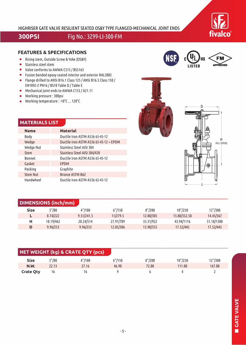
FEATURES & SPECIFICATIONS
Rising stem, Outside Screw & Yoke (OS&Y)Stainless steel stem
Valve conforms to AWWA C515 / BS5163Fusion bonded epoxy coated interior and exterior RAL3002Flange drilled to ANSI B16.1 Class 125 / ANSI B16.5 Class 150 / EN1092-2 PN16 / BS10 Table D / Table EWorking pressure : 300psiWorking temperature : -10°C ... 120°C
HIGHRISER GATE VALVE RESILIENT SEATED OS&Y TYPE FLANGED ENDS
300PSI Fig No.: 3299-LI-300-FLA

- 2 -
GA
TE
VA
LVE
Name Material
MATERIALS LIST
DIMENSIONS (inch/mm)
NET WEIGHT (kg) & CRATE QTY (pcs)
2”/50
7.00/178
16.18/411
7.20/183
2.37/60.3
2.5”/65
7.50/191
16.18/411
7.20/183
2.87/73 2.99/76.1
3”/80
8.00/203
18.19/462
9.96/253
2.37/88.9
4”/100
9.00/229
20.24/514
9.96/253
4.5/114.3
5”/125
10.00/254
24.76/629
12.05/306
5.56/141.3 5.5/139.7
6”/150
10.50/267
27.91/709
12.05/306
6.63/168.3 6.5/165.1
8”/200
11.50/292
36.18/919
13.98/355
8.63/219.1
10”/250
13.00/330
43.94/1116
17.52/445
10.75/273
12”/300
14.00/356
51.18/1300
17.52/445
12.75/323.9
12”/300167.00
2
10”/250111.00
4
8”/20072.00
6
6”/15046.90
9
5”/12540.30
9
4”/10027.16
16
3”/8022.13
16
2.5”/6518.91
25
2”/5017.64
25
Size
N.W.
Crate Qty
Size
L
H
D
D3
Body
Wedge
Wedge Nut
Stem
Bonnet
Gasket
Packing
Stem Nut
Handwheel
Ductile Iron ASTM A536 65-45-12Ductile Iron ASTM A536 65-45-12 + EPDMStainless Steel AISI 304Stainless Steel AISI 304/420Ductile Iron ASTM A536 65-45-12EPDM
GraphiteBronze ASTM B62Ductile Iron ASTM A536 65-45-12
FEATURES & SPECIFICATIONS
Rising stem, Outside Screw & Yoke (OS&Y)Stainless steel stem
Valve conforms to AWWA C515 / BS5163Fusion bonded epoxy coated interior and exterior RAL3002Flange drilled to ANSI B16.1 Class 125 / ANSI B16.5 Class 150 /EN1092-2 PN16 / BS10 Table D / Table EGrooved ends to suit ANSI / AWWA and BS Pipe sizeWorking pressure : 300psiWorking temperature : -10°C ... 120°C
HIGHRISER GATE VALVE RESILIENT SEATED OS&Y TYPE FLANGED-GROOVED ENDS
300PSI Fig No.: 3299-LI-300-FG

- 3 -
GA
TE
VA
LVE
Name Material
MATERIALS LIST
DIMENSIONS (inch/mm)
NET WEIGHT (kg) & CRATE QTY (pcs)
12”/300167.00
2
10”/250111.00
4
8”/20072.00
6
6”/15046.90
9
5”/12540.30
9
4”/10027.16
16
3”/8022.13
16
2.5”/6518.91
25
2”/5017.64
25
Size
N.W.
Crate Qty
2”/50
7.00/178
16.18/411
7.20/183
2.37/60.3
2.5”/65
7.50/191
16.18/411
7.20/183
2.87/73 2.99/76.1
3”/80
8.00/203
18.19/462
9.96/253
2.37/88.9
4”/100
9.00/229
20.24/514
9.96/253
4.5/114.3
5”/125
10.00/254
24.76/629
12.05/306
5.56/141.3 5.5/139.7
6”/150
10.50/267
27.91/709
12.05/306
6.63/168.3 6.5/165.1
8”/200
11.50/292
36.18/919
13.98/355
8.63/219.1
10”/250
13.00/330
43.94/1116
17.52/445
10.75/273
12”/300
14.00/356
51.18/1300
17.52/445
12.75/323.9
Size
L
H
D
D3
Body
Wedge
Wedge Nut
Stem
Bonnet
Gasket
Packing
Stem Nut
Handwheel
Ductile Iron ASTM A536 65-45-12Ductile Iron ASTM A536 65-45-12 + EPDMStainless Steel AISI 304Stainless Steel AISI 304/420Ductile Iron ASTM A536 65-45-12EPDM
GraphiteBronze ASTM B62Ductile Iron ASTM A536 65-45-12
FEATURES & SPECIFICATIONS
Rising stem, Outside Screw & Yoke (OS&Y)Stainless steel stem
Valve conforms to AWWA C515 / BS5163Fusion bonded epoxy coated interior and exterior RAL3002Grooved ends to suit ANSI / AWWA and BS Pipe sizeWorking pressure : 300psiWorking temperature : -10°C ... 120°C
HIGHRISER GATE VALVE RESILIENT SEATED OS&Y TYPE GROOVED-GROOVED ENDS
300PSI Fig No.: 3299-LI-300-GG

- 4 -
GA
TE
VA
LVE
Name Material
MATERIALS LIST
DIMENSIONS (inch/mm)
NET WEIGHT (kg) & CRATE QTY (pcs)
3”/809.49/241
18.19/4629.96/253
3”/8022.13
16
Size
N.W.
Crate Qty
4”/10027.16
16
6”/15046.90
9
8”/20072.00
6
10”/250111.00
4
12”/300167.00
2
Size
L
H
D
4”/10010.00/25420.24/5149.96/253
6”/15011.50/29227.91/70912.05/306
8”/20012.52/31836.31/92213.98/355
10”/25014.76/375
43.94/111617.52/445
12”/30014.88/378
51.18/130017.52/445
Body
Wedge
Wedge Nut
Stem
Bonnet
Gasket
Packing
Stem Nut
Handwheel
Ductile Iron ASTM A536 65-45-12Ductile Iron ASTM A536 65-45-12 + EPDMStainless Steel AISI 304Stainless Steel AISI 304/420Ductile Iron ASTM A536 65-45-12EPDM
GraphiteBronze ASTM B62Ductile Iron ASTM A536 65-45-12
FEATURES & SPECIFICATIONS
Rising stem, Outside Screw & Yoke (OS&Y)Stainless steel stem
Valve conforms to AWWA C515 / BS5163Fusion bonded epoxy coated interior and exterior RAL3002Mechanical joint ends to AWWA C153 / A21.11Working pressure : 300psiWorking temperature : -10°C ... 120°C
HIGHRISER GATE VALVE RESILIENT SEATED OS&Y TYPE MECHANICAL JOINT ENDS
300PSI Fig No.: 3299-LI-300-MJ
- 5 -- 5 -
GA
TE
VA
LVE
Name Material
HIGHRISER GATE VALVE RESILIENT SEATED OS&Y TYPE FLANGED-MECHANICAL JOINT ENDS
MATERIALS LIST
DIMENSIONS (inch/mm)
NET WEIGHT (kg) & CRATE QTY (pcs)
Body
Wedge
Wedge Nut
Stem
Bonnet
Gasket
Packing
Stem Nut
Handwheel
Ductile Iron ASTM A536 65-45-12Ductile Iron ASTM A536 65-45-12 + EPDMStainless Steel AISI 304Stainless Steel AISI 304/420Ductile Iron ASTM A536 65-45-12EPDM
GraphiteBronze ASTM B62Ductile Iron ASTM A536 65-45-12
3”/808.74/222
18.19/4629.96/253
3”/8022.13
16
4”/10027.16
16
6”/15046.90
9
8”/20072.00
6
10”/250111.00
4
12”/300167.00
2
4”/1009.51/241.520.24/5149.96/253
6”/15011/279.5
27.91/70912.05/306
8”/20012.00/30533.31/92213.98/355
10”/25013.88/352.5043.94/111617.52/445
12”/30014.45/367
51.18/130017.52/445
Size
L
H
D
Size
N.W.
Crate Qty
FEATURES & SPECIFICATIONS
Rising stem, Outside Screw & Yoke (OS&Y)Stainless steel stem
Valve conforms to AWWA C515 / BS5163Fusion bonded epoxy coated interior and exterior RAL3002Flange drilled to ANSI B16.1 Class 125 / ANSI B16.5 Class 150 /EN1092-2 PN16 / BS10 Table D / Table EMechanical joint ends to AWWA C153 / A21.11Working pressure : 300psiWorking temperature : -10°C ... 120°C
Fig No.: 3299-LI-300-FM300PSI

- 6 -
GA
TE
VA
LVE
Name Material
HIGHRISER GATE VALVE RESILIENT SEATED NRS TYPE FLANGED ENDS
MATERIALS LIST
DIMENSIONS (inch/mm)
NET WEIGHT (kg) & CRATE QTY (pcs)
Body
Wedge Disc
Disc Nut
Stem
Gasket
Bonnet
Thrust CollarGland
Wrench NutPost Plate
Ductile Iron ASTM A536 65-45-12Ductile Iron ASTM A536 65-45-12 + EPDMBronze ASTM B62Stainless Steel AISI 304/420EPDM
Ductile Iron ASTM A536 65-45-12Bronze ASTM B62Ductile Iron ASTM A536 65-45-12Ductile Iron ASTM A536 65-45-12Ductile Iron ASTM A536 65-45-12
2”/507.00/178
10.98/27912.01/305
2.5”/657.5/191
10.98/27912.01/305
3”/808.00/203
11.99/304.5012.01/305
4”/1009.00/229
12.76/32412.01/305
5”/12510.00/254
15.49/393.5012.01/305
6”/15010.50/26716.85/42812.01/305
8”/20011.50/29221.14/53712.01/305
10”/25013.00/33025.20/64012.01/305
12”/30014.00/35628.46/72312.01/305
2”/5024.00
9
2.5”/6525.30
9
3”/8027.50
9
4”/10035.00
9
5”/12542.00
9
6”/15050.00
9
8”/20083.00
9
10”/250123.50
4
12”/300175.50
2
Size
L
H
D
Size
N.W.
Crate Qty
FEATURES & SPECIFICATIONS
Non-rising stem
Stainless steel stem
Valve conforms to AWWA C515 / BS5163Fusion bonded epoxy coated interior and exterior RAL3002Flange drilled to ANSI B16.1 Class 125 / ANSI B16.5 Class 150 /EN1092-2 PN16 / BS10 Table D / Table EWorking pressure : 300psiWorking temperature : -10°C ... 120°CAll valves provided with 2” (50mm) operating nut
Fig No.: 3288-LI-300-FLA300PSI

- 7 -
GA
TE
VA
LVE
Name Material
HIGHRISER GATE VALVE RESILIENT SEATED NRS TYPE FLANGED-GROOVED ENDS
MATERIALS LIST
DIMENSIONS (inch/mm)
NET WEIGHT (kg) & CRATE QTY (pcs)
2”/50
7.00/178
10.98/279
12.01/305
2.37/60.3
Size
L
H
D
D3
2.5”/65
7.5/191
10.98/279
12.01/305
2.87/73 2.99/76.1
3”/80
8.00/203
12.01/305
12.01/305
2.37/88.9
4”/100
9.00/229
12.76/324
12.01/305
4.5/114.3
5”/125
10.00/254
15.51/394
12.01/305
5.56/141.3 5.5/139.7
6”/150
10.50/267
16.85/428
12.01/305
6.63/168.3 6.5/165.1
8”/200
11.50/292
21.14/537
12.01/305
8.63/219.1
10”/250
13.00/330
25.20/640
12.01/305
10.75/273
12”/300
14.00/356
28.46/723
12.01/305
12.75/323.9
Body
Wedge Disc
Disc Nut
Stem
Gasket
Bonnet
Thrust CollarGland
Wrench NutPost Plate
Ductile Iron ASTM A536 65-45-12Ductile Iron ASTM A536 65-45-12 + EPDMBronze ASTM B62Stainless Steel AISI 304/420EPDM
Ductile Iron ASTM A536 65-45-12Bronze ASTM B62Ductile Iron ASTM A536 65-45-12Ductile Iron ASTM A536 65-45-12Ductile Iron ASTM A536 65-45-12
2”/5024.00
9
2.5”/6525.30
9
3”/8027.50
9
4”/10035.00
9
5”/12542.00
9
6”/15050.00
9
8”/20083.00
9
10”/250123.50
4
12”/300175.50
2
Size
N.W.
Crate Qty
FEATURES & SPECIFICATIONS
Non-rising stem
Stainless steel stem
Valve conforms to AWWA C515 / BS5163Fusion bonded epoxy coated interior and exterior RAL3002Flange drilled to ANSI B16.1 Class 125 / ANSI B16.5 Class 150 /EN1092-2 PN16 / BS10 Table D / Table EGrooved ends to suit ANSI / AWWA and BS Pipe sizeWorking pressure : 300psiWorking temperature : -10°C ... 120°CAll valves provided with 2” (50mm) operating nut
300PSI Fig No.: 3288-LI-300-FG
- 8 -
GA
TE
VA
LVE
Name Material
HIGHRISER GATE VALVE RESILIENT SEATED NRS TYPE GROOVED-GROOVED ENDS
MATERIALS LIST
DIMENSIONS (inch/mm)
NET WEIGHT (kg) & CRATE QTY (pcs)
2”/50
7.00/178
10.98/279
12.01/305
2.37/60.3
Size
L
H
D
D3
2.5”/65
7.5/191
10.98/279
12.01/305
2.87/73 2.99/76.1
3”/80
8.00/203
12.01/305
12.01/305
2.37/88.9
4”/100
9.00/229
12.76/324
12.01/305
4.5/114.3
5”/125
10.00/254
15.51/394
12.01/305
5.56/141.3 5.5/139.7
6”/150
10.50/267
16.85/428
12.01/305
6.63/168.3 6.5/165.1
8”/200
11.50/292
21.14/537
12.01/305
8.63/219.1
10”/250
13.00/330
25.20/640
12.01/305
10.75/273
12”/300
14.00/356
28.46/723
12.01/305
12.75/323.9
Body
Wedge Disc
Disc Nut
Stem
Gasket
Bonnet
Thrust CollarGland
Wrench NutPost Plate
Ductile Iron ASTM A536 65-45-12Ductile Iron ASTM A536 65-45-12 + EPDMBronze ASTM B62Stainless Steel AISI 304/420EPDM
Ductile Iron ASTM A536 65-45-12Bronze ASTM B62Ductile Iron ASTM A536 65-45-12Ductile Iron ASTM A536 65-45-12Ductile Iron ASTM A536 65-45-12
2”/5024.00
9
2.5”/6525.30
9
3”/8027.50
9
4”/10035.00
9
5”/12542.00
9
6”/15050.00
9
8”/20083.00
9
10”/250123.50
4
12”/300175.50
2
Size
N.W.
Crate Qty
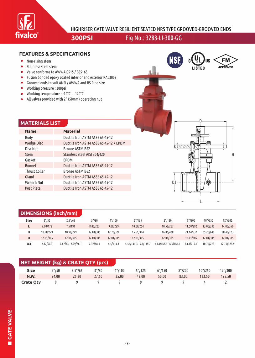
FEATURES & SPECIFICATIONS
Non-rising stem
Stainless steel stem
Valve conforms to AWWA C515 / BS5163Fusion bonded epoxy coated interior and exterior RAL3002Grooved ends to suit ANSI / AWWA and BS Pipe sizeWorking pressure : 300psiWorking temperature : -10°C ... 120°CAll valves provided with 2” (50mm) operating nut
300PSI Fig No.: 3288-LI-300-GG

- 9 -
GA
TE
VA
LVE
Name Material
HIGHRISER GATE VALVE RESILIENT SEATED NRS TYPE MECHANICAL JOINT ENDS
MATERIALS LIST
DIMENSIONS (inch/mm)
NET WEIGHT (kg) & CRATE QTY (pcs)
Body
Wedge Disc
Disc Nut
Stem
Gasket
Bonnet
Thrust CollarGland
Wrench NutPost Plate
Ductile Iron ASTM A536 65-45-12Ductile Iron ASTM A536 65-45-12 + EPDMBronze ASTM B62Stainless Steel AISI 304/402EPDM
Ductile Iron ASTM A536 65-45-12Bronze ASTM B62Ductile Iron ASTM A536 65-45-12Ductile Iron ASTM A536 65-45-12Ductile Iron ASTM A536 65-45-12
3”/809.49/241
12.01/30512.01/305
3”/8027.50
9
4”/10035.00
9
6”/15050.00
9
8”/20083.00
9
10”/250123.50
4
12”/300175.50
2
4”/10010.00/25412.76/32412.01/305
6”/15011.50/29216.85/42812.01/305
8”/20012.52/31821.14/53712.01/305
10”/25014.76/37525.20/64012.01/305
12”/30014.88/37828.46/72312.01/305
Size
L
H
D
Size
N.W.
Crate Qty
FEATURES & SPECIFICATIONS
Non-rising stem
Stainless steel stem
Valve conforms to AWWA C515 / BS5163Fusion bonded epoxy coated interior and exterior RAL3002Mechanical joint ends to AWWA C153 / A21.11Working pressure : 300psiWorking temperature : -10°C ... 120°CAll valves provided with 2” (50mm) operating nut
300PSI Fig No.: 3288-LI-300-MJ

- 10 -
GA
TE
VA
LVE
Name Material
HIGHRISER GATE VALVE RESILIENT SEATED NRS TYPE FLANGED-MECHANICAL JOINT ENDS
MATERIALS LIST
DIMENSIONS (inch/mm)
NET WEIGHT (kg) & CRATE QTY (pcs)
Body
Wedge Disc
Disc Nut
Stem
Gasket
Bonnet
Thrust CollarGland
Wrench NutPost Plate
Ductile Iron ASTM A536 65-45-12Ductile Iron ASTM A536 65-45-12 + EPDMBronze ASTM B62Stainless Steel AISI 304/402EPDM
Ductile Iron ASTM A536 65-45-12Bronze ASTM B62Ductile Iron ASTM A536 65-45-12Ductile Iron ASTM A536 65-45-12Ductile Iron ASTM A536 65-45-12
3”/808.74/222.012.01/30512.01/305
4”/1009.51/241.512.76/32412.01/305
6”/15011.00/279.516.85/42812.01/305
8”/20012.01/30521.14/53712.01/305
10”/25013.88/352.525.20/64012.01/305
12”/30014.45/367.028.46/72312.01/305
Size
L
H
D
3”/8027.50
9
4”/10035.00
9
6”/15050.00
9
8”/20083.00
9
10”/250123.50
4
12”/300175.50
2
Size
N.W.
Crate Qty
FEATURES & SPECIFICATIONS
Non-rising stem
Stainless steel stem
Valve conforms to AWWA C515 / BS5163Fusion bonded epoxy coated interior and exterior RAL3002Flange drilled to ANSI B16.1 Class 125 / ANSI B16.5 Class 150 /EN1092-2 PN16 / BS10 Table D / Table EMechanical joint ends to AWWA C153 / A21.11Working pressure : 300psiWorking temperature : -10°C ... 120°CAll valves provided with 2” (50mm) operating nut
300PSI Fig No.: 3288-LI-300-FM
- 11 -
GA
TE
VA
LVE
FIRERISER GATE VALVE OS&Y TYPE FLANGED ENDS
Name Material
MATERIALS LIST
DIMENSIONS (inch/mm)
NET WEIGHT (kg) & CRATE QTY (pcs)
Body
Wedge
Wedge Nut
Stem
Bonnet
Gasket
Packing
Stem Nut
Handwheel
Ductile Iron ASTM A536 65-45-12Ductile Iron ASTM A536 65-45-12 + EPDMStainless Steel AISI 304Stainless Steel AISI 304/420Ductile Iron ASTM A536 65-45-12EPDM
GraphiteBronze ASTM B62Ductile Iron ASTM A536 65-45-12
14”/35015.00/381
62.09/157720.00/508
14”/350277.00
1
16”/400366.00
1
18”/450530.00
1
20”/500754.00
1
24”/6001020.00
1
16”/40015.98/406
70.87/180021.97/558
18”/45017.01/432
80.63/204824.02/610
20”/50017.99/457
90.43/229724.02/610
24”/60020.00/508
102.36/260030.00/762
Size
L
H
D
Size
N.W.
Crate Qty
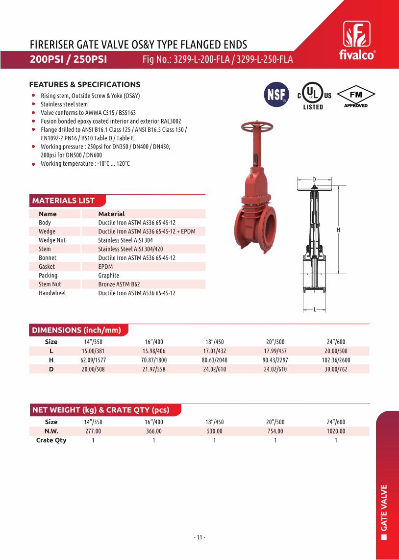
FEATURES & SPECIFICATIONS
Rising stem, Outside Screw & Yoke (OS&Y)Stainless steel stem
Valve conforms to AWWA C515 / BS5163Fusion bonded epoxy coated interior and exterior RAL3002Flange drilled to ANSI B16.1 Class 125 / ANSI B16.5 Class 150 /EN1092-2 PN16 / BS10 Table D / Table EWorking pressure : 250psi for DN350 / DN400 / DN450, 200psi for DN500 / DN600Working temperature : -10°C ... 120°C
Fig No.: 3299-L-200-FLA / 3299-L-250-FLA200PSI / 250PSI

- 12 -
GA
TE
VA
LVE
Name Material
FIRERISER GATE VALVE NRS TYPE FLANGED ENDS
MATERIALS LIST
DIMENSIONS (inch/mm)
NET WEIGHT (kg) & CRATE QTY (pcs)
Body
Wedge Disc
Disc Nut
Stem
Gasket
Bonnet
Thrust CollarGland
Wrench NutPost Plate
Ductile Iron ASTM A536 65-45-12Ductile Iron ASTM A536 65-45-12 + EPDMASTM B62 C83600
Stainless Steel AISI 431EPDM
Ductile Iron ASTM A536 65-45-12Bronze ASTM B62Ductile Iron ASTM A536 65-45-12Ductile Iron ASTM A536 65-45-12Ductile Iron ASTM A536 65-45-12
14”/35015.00/38133.94/86212.01/305
16”/40015.98/40636.93/93812.01/305
18”/45017.01/432
41.61/105712.01/305
20”/50017.99/457
44.96/114212.01/305
24”/60020.00/508
50.98/129512.01/305
14”/350232.00
1
16”/400308.00
1
18”/450446.00
1
20”/500636.00
1
24”/600848.00
1
Size
L
H
D
Size
N.W.
Crate Qty
FEATURES & SPECIFICATIONS
Non-rising stem
Stainless steel stem
Valve conforms to AWWA C515Fusion bonded epoxy coated interior and exterior RAL3002Flange drilled to ANSI B16.1 Class 125 / ANSI B16.5 Class 150 /EN1092-2 PN16 / BS10 Table D / Table EWorking pressure : 250psi for DN350 / DN400 / DN450, 200psi for DN500 / DN600Working temperature : -10°C ... 120°CAll valves provided with 2” (50mm) operating nut
Fig No.: 3288-L-200-FLA / 3288-L-250-FLA250PSI

- 13 -
IND
ICA
TO
R P
OS
T
mm inch
HMin. Bury Depth(mm/inch)
Max. Bury Depth(mm/inch)
ValveSize
Ground Line
0~
34
.25
11
"
30
"
26
24
25
23
22
21
20
19
1
6
3
2
5
8
10
7
4
15
9
1211
13
14
17
16
18
Name MaterialNo. QTY.
1. Remove the top section from the top of the Indicator Post assembly.2. Cut the required length off the bottom of the Standpipe for the Gound Line to match up with Standpipe Gound Line mark.3. Set the “OPEN” and “SHUT” targets for the apporpriate valve size.4. Reattach the Top Section to the top of the Indicator Post assembly.
INDICATOR POST
MATERIALS LIST
BURY DEPTH
FIELD ADJUSTMENT
1
2
3
45
6
7
8
9
10
11
12
13
1415
16
17
18
19
20
21
22
23
24
25
26
1
1
2
2
1
1
442
2
441
6
6
1
441
1
1
1
1
1
1
1
Locking WrenchOperating NutHex Nut ScrewHex NutSnap RingTaget Carrier Nut
Taget
Hex Cap NutWindow Glass
Window Glass Gasket
Hex Cap ScrewHex NutBody
Hex Cap ScrewHex Nut ScrewHex NutBase Flange
Hex NutCrane CouplingCotter Pin
Stand PipeStem
Plug
Cover
Cross Recessed
Countersunk HeadScrew
Locking Nose
ASTM A126B
ASTM B62
ASTM A105
ASTM A105
AISI 066
ASTM B62
ASTM B108
ASTM A105
LEXAN-UMPTFE
ASTM A105
ASTM A105
ASTM A536
ASTM A105
ASTM A105
ASTM A126B
ASTM A105
ASTM A105
ASTM A536
AISI 304ASTM A53
AISI 1045AISI 304ASTM A126B
AISI 304
ASTM 307 B
4”5”6”8”
10”12”
757 / 29.8”818 / 32.2”
852 / 33.54”937 / 36.89”
1032 / 40.63”1118 / 44.02”
1627 / 64.06”1688 / 66.46”1722 / 67.8”
1807 / 71.14”1902 / 74.88”1988 / 78.27”
217
278
312
397
492578
8.54”10.94”12.28”15.63”19.37”22.76”
Fig No.: IPO888
11.18”

- 14 -
IND
ICA
TO
R P
OS
T
mm inch mm inchValve Size
Min. BuryDepth (inch)
Max. BuryDepth (inch)
H1 H2
Ground Line
37
RA
NG
E O
D S
PA
CE0~
2800
34
35
24
36
23
33
32
14
305
111
31
29
30
25
26
28
27
13
16
10
5
17
20
22
21
1918
1514
1211
9
87
6
43
2
1
1039
1305
135
OPEN
SHUT
No. Name Material
1. Remove the top section from the top of the Indicator Post assembly.2. Cut the required length off the bottom of the Standpipe for the Gound Line to match up with Standpipe Gound Line mark.3. Set the “OPEN” and “SHUT” targets for the apporpriate valve size.4. Reattach the Top Section to the top of the Indicator Post assembly.
LARGE NRS INDICATOR POST
MATERIALS LIST
BURY DEPTH FIELD ADJUSTMENT
1
2
3
45
6
7
8
9
10
11
12
13
1415
16
17
18
19
20
21
22
23
2425
26
27
28
29
30
31
32
33
3435
36
37
Locking WrenchOperating NutBolt
Nut
Flat WasherShap RingTaget Carrier Nut
Target
Bolt
Flat WasherWindow Gland
Window Glass
Gasket
Bolt
Spring WasherNut
Body
Bolt
Nut
Base Flange
Bolt
Nut
Crane CouplingCotter Pin
Stand PipeStem 1” SquarePlug
Top CoverScrew
Lock Nose
Reducer
Bolt
Nut
Wrench NutWasherHex. Socket CapScrew
Spring Washer
ASTM A536
ASTM B62/A351 CF8ASTM A105
ASTM A105
ASTM A105
AISI 606
ASTM B62
ASTM B108
ASTM A105
ASTM A105
ASTM A307B
LEXAN-UN STABILIZEEPDM
ASTM A105
ASTM A105
ASTM A105
ASTM A536
ASTM A105
ASTM A105
ASTM A126B
ASTM A105
ASTM A105
ASTM A536
AISI 304ASTM A536
AISI 1045AISI 304ASTM A126B
AISI 304ASTM A307B
PARTS
ASTM A105
ASTM A105
ASTM A536
AISI 304AISI 304
AISI 304
14”16”18”20”24”
50.87”53.82”58.54”61.89”67.87”
158.35”161.30”166.02”169.37”175.35”
741816
936
1021
1173
29.17”32.13”36.85”40.20”46.18”
889.5964.510841169
1344.5
35.02”37.97”42.68”46.02”52.93”
Fig No.: IPOL888

- 15 -
IND
ICA
TO
R P
OS
T
13
-1/4
"
14 3/4"
3"
17
-1/4
"(1
2")
23
12"
10-1/2"
22
3/4
"
EQUALLY4-3/4"
2421
13
18
20
19
17
16
1514
12
11
10
9
8
76
5
4
3
2
1
OPEN
Name MaterialNo. QTY.
1. Remove the top section from the top of the Indicator Post assembly.2. Set the “OPEN” and “SHUT” targets for the apporpriate valve size.3. Reattach the Top Section to the top of the Indicator Post assembly.
INDICATOR POST WALL TYPE
MATERIALS LIST
FIELD ADJUSTMENT
1
2
3
45
6
7
8
9
10
11
12
13
1415
16
17
18
19
20
21
22
23
24
1
1
1
1
1
2
2
1
1
442
2
441
1
1
1
1
1
1
1
1
Lifting Eye Bolt
Hex NutWasherHand WheelOperating NutHex Cap ScrewHex NutSnap RingTarget Carrier Nut
Target
Hex Cap ScrewWindow Glass
Window Glass Gasket
Hex Cap ScrewHex NutBody
Stand PipeStem
Cotter Pin
Crane CouplingPlug
Cover
Cross Recessed
Countersunk HeadScrew
Locking Nose
ASTM A105
ASTM A105
ASTM A105
ASTM A536
ASTM B62
ASTM A105
ASTM A105
AISI 066
ASTM B62
ASTM B108
ASTM A105
LEXAN-UMPTFE
ASTM A105
ASTM A105
ASTM A536
ASTM A53
AISI 1045AISI 304ASTM A536
AISI 304ASTM A126B
AISI 304
ASTM 307B
Fig No.: WPO999

- 16 -
IND
ICA
TO
R P
OS
T
NOTE: Ensure that the Non-Rising Stem Gate Valve is in the fully open postition before installing the Vertical IndicatorPost.
1) Disassemble the Indicator Post
Take off the Locking Wrench (11). Slide off the Top Section(20) together with the Operating Nut (19) and the square Stem (9) as well as the Crane Coupling (3) and ensure that all other accessories attached from the end of the Body (10)by loosening two Hex Cap screws (24) and Square Nut (23), slide off the Body (10) from the Standpipe (8) by loosening two Hex Cap Screws and Hex Nut. Loosen the two Hex Cap Screws and Hex Nut. Slide off the Standpipe (8) from the Base Flange (5).
2) Install the Base Flange and Standpipe
Attach the Base Flange (5) together with the Standpipe to the Post Flange of the Non-Rising Stem Gate Valve using the four Cap Screws (1) and Hex Nut.
3) Adjust the Grade Line Mark
Pull in and lower the Body (10) over the Standpipe (8) untilthe Gound Line Mark on the Body (10) is the same height as ground level. Tighten the two Hex Cap Screws and Hex Nut.
4) Adjust the Square Stem
Lower the Stem (9) into Body (10) Standpipe (8) such that the Crane Coupling (13) fits over the Operating nut of the Non-Rising Stem Gate Valve. Ensure that the Stem (9) engages the Operating Nut (19) a minimum of 2 inches butno more than 4.5 inches. To check for correct engagement, the end of stem should be from 2 to 4.5 inches below the topof the Body (10).
5) Adjust the Targets
Remove the Target Carrier Assembly (12+13+14) from insidethe Body (10) by rotating the Operating Nut (19) counterclockweise. The Open Target (16) and Shut Target (not shown) are adjusted up or down on the Target CarrierAssembly (12+13+14) by pulling the middle section of the Target (Open and Shut) a small distance away from the TargetCarrier Assembly (12+13+14) and sliding the Target (Open and Shut) up or down as desired. If the Non-Rising Stem Gate Valveis opened left: move the two Open Targets (16) to the very top of the Target Carrier Assembly (12+13+14). Locate the two ShutTargets (not shown) according to the Non-Rising Stem GateValve size (stem) turning distance. If the Non-Rising Stem GateValve is opened right: move the two Shut Targets (not shown) to the very top of the Target Carrier Assembly (12+13+14).
Locate the two Open Targets (16) according to the Non-Rising Stem Gate Valve is opened right: move the two Shut Targets (not shown) to the very top of the Target Carrier Assembly (12+13+14).
6) Final Assembly and Test
Insert the Target Carrier Assembly (12+13+14) back into the Top Section (20) by rotating the Operating Nut (19) clockwise.Rotate until the Open Target (16) is centered in the window of the window of the Body (10) which corresponds with the Non-Rising Stem Gate Valve being in the open position. Lowerthe Top Section (20) with Target Carrier Assembly (12+13+14) onto the Body (10), assuring that the Stem (9) Engages with the Operating Nut (19) at least 2 inches but not more than 4.5 inches. Secure the Top Section (20) to the Body (10) by tightening the Cap Screw (24) and Square Nut (23). Close the Non-Rising Stem Gate Valve and make sure that the Shut Target (not shown) is properly centered in the window of the Body (10) and adjust as necessary.
Oil the baring in the Top Section (20) at least once per year by adding several drops of oil in the hole located on the topof the Operating Nut (19).
INDICATOR POST ADJUSTMENT
INSTALLATION
MAINTENANCE

- 17 -
CH
EC
K V
ALV
E
4"~12"
Name Material
HIGHRISER SWING CHECK VALVE RESILIENT SEATED FLANGED ENDS
2"~3"
MATERIALS LIST
DIMENSIONS (inch/mm)
NET WEIGHT (kg) & CRATE QTY (pcs)
Body
Cover
ClapperClapper ArmHinge PinSeat
Ductile Iron A536 65-45-12Ductile Iron A536 65-45-12Ductile Iron A536 65-45-12 + EPDMDuctile Iron A536 65-45-12Stainless Steel AISI 304Bronze ASTM B62Stainless Steel AISI 304
2”/508/203
4.60/117
2.5”/6510/254
5.04/128
3”/8011/279
5.21/132.5
4”/10013/330
8.76/222.5
5”/12514/356
11.42/290
6”/15016/406
11.69/297
8”/20019.5/495
14.37/365
10”/25022/559
16.34/417.5
12”/30026/660
17.83/453
2”/5012.00
30
2.5”/6517.50
20
3”/8022.00
20
4”/10034.00
12
5”/12558.00
8
6”/15067.30
6
8”/200120.00
6
10”/250174.00
2
12”/300246.00
2
Size
L
H
Size
N.W.
Crate Qty
FEATURES & SPECIFICATIONS
Bolted bonnet
Swing typeValve conforms to AWWA C508, clear waterwayFusion bonded epoxy coated RAL3002Flange drilled to ANSI B16.1 Class 125 / ANSI B16.5 Class 150 /EN1092-2 PN16 / BS10 Table D / Table EWorking pressure : 300psiWorking temperature : -10°C ... 110°C
Fig No.: 5201-LI-300-FLA300PSI

- 18 -
CH
EC
K V
ALV
E
5201-365-GGI is a non-return valve which permits water flow in one directionand prevents flow in reverse direction. This function is realized by a spring loaded EPDM sealed carbon steel clapper and a broadened bronze seat, to provide a long service time and leak-free sealing. It is widely used with various configurations in fire pump room, fire sprinkler systems, fire department connections, gravity pressure tank or by-pass connections etc.
Part Specification
HIGHRISER SWING CHECK VALVE GROOVED ENDS
MATERIALS LIST
DESCRIPTION
DIMENSIONS (inch/mm)
NET WEIGHT (kg) & CRATE QTY (pcs)
Body
Seat
ClapperClapper ArmWasherHexagonal Slot Thin NutSplit Pin
Ductile Iron ASTM A536 65-45-12Bronze ASTM B62 C83600Carbon Steel WCB Q235 + EPDM
Stainless Steel AISI 304Stainless Steel AISI 304Stainless Steel AISI 304Stainless Steel AISI 304
2”/506.65/169
5.69/144.652.37/60.3
2.5”/657.99/2036.02/153
2.87/73 3.0/76.1
3”/808.39/213
6.71/170.53.5/88.9
4”/1009.65/245
7.89/200.54.5/114.3
5”/12510.54/2679.33/237
5.5/139.7 5.56/141.3
6”/15011.50/29210.75/273
6.5/165.1 6.63/168.3
8”/20014.02/35612.91/3288.63/219.1
10”/25017.01/43215.24/38710.75/273
12”/30019.49/495
17.66/448.512.75/323.9
2”/503.5100
2.5”/654.5100
3”/806
95
4”/1009.550
5”/12518
32
6”/15019.532
8”/20033
6
10”/25053
6
12”/300942
Size
L
H
OD
Size
N.W.
Crate Qty
FEATURES & SPECIFICATIONS
Swing typeSpring loaded EPDM sealed carbon steel clapperFusion bonded epoxy coated RAL3002Grooved ends to suit ANSI / AWWA and BS Pipe sizeWorking pressure : 365psiWorking temperature : 0°C ... 80°C
Fig No.: 5201-365-GGI365PSI
H
- 19 -
CH
EC
K V
ALV
E
Note: Pipe tappered thread hole size has to be specified by ordering. If non-standard thread, please contact Fivalco or its local distributor.
Pipe TapperedStandard Thread
Size
Pipe TapperedOptional Thread
Size
Nominal Size(inch/mm)
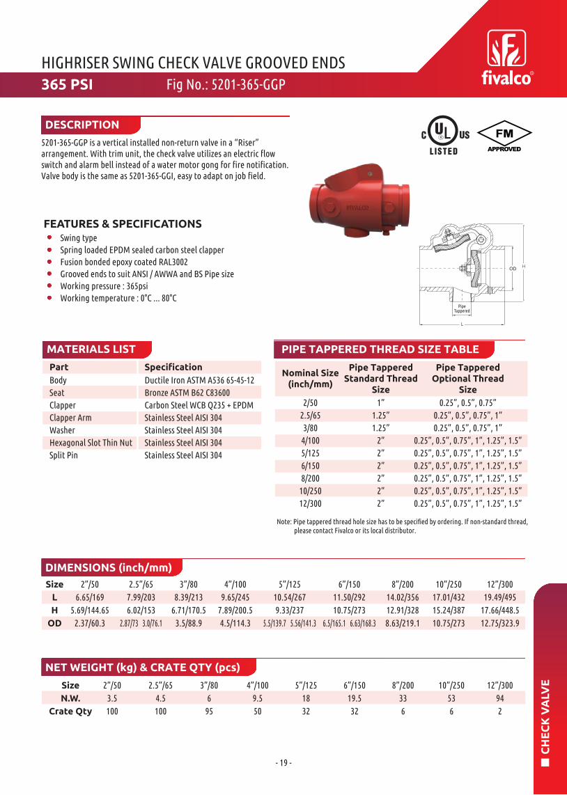
5201-365-GGP is a vertical installed non-return valve in a “Riser” arrangement. With trim unit, the check valve utilizes an electric flow switch and alarm bell instead of a water motor gong for fire notification. Valve body is the same as 5201-365-GGI, easy to adapt on job field.
HIGHRISER SWING CHECK VALVE GROOVED ENDS
DESCRIPTION
PIPE TAPPERED THREAD SIZE TABLE
Part Specification
MATERIALS LIST
Body
Seat
ClapperClapper ArmWasherHexagonal Slot Thin NutSplit Pin
Ductile Iron ASTM A536 65-45-12Bronze ASTM B62 C83600Carbon Steel WCB Q235 + EPDM
Stainless Steel AISI 304Stainless Steel AISI 304Stainless Steel AISI 304Stainless Steel AISI 304
2/502.5/653/80
4/1005/1256/1508/200
10/25012/300
1”1.25”1.25”
2”2”2”2”2”2”
0.25”, 0.5”, 0.75”0.25”, 0.5”, 0.75”, 1”0.25”, 0.5”, 0.75”, 1”
0.25”, 0.5”, 0.75”, 1”, 1.25”, 1.5”0.25”, 0.5”, 0.75”, 1”, 1.25”, 1.5”0.25”, 0.5”, 0.75”, 1”, 1.25”, 1.5”0.25”, 0.5”, 0.75”, 1”, 1.25”, 1.5”0.25”, 0.5”, 0.75”, 1”, 1.25”, 1.5”0.25”, 0.5”, 0.75”, 1”, 1.25”, 1.5”
DIMENSIONS (inch/mm)
NET WEIGHT (kg) & CRATE QTY (pcs)
2”/506.65/169
5.69/144.652.37/60.3
2.5”/657.99/2036.02/153
2.87/73 3.0/76.1
3”/808.39/213
6.71/170.53.5/88.9
4”/1009.65/245
7.89/200.54.5/114.3
5”/12510.54/2679.33/237
5.5/139.7 5.56/141.3
6”/15011.50/29210.75/273
6.5/165.1 6.63/168.3
8”/20014.02/35612.91/3288.63/219.1
10”/25017.01/43215.24/38710.75/273
12”/30019.49/495
17.66/448.512.75/323.9
2”/503.5100
2.5”/654.5100
3”/806
95
4”/1009.550
5”/12518
32
6”/15019.532
8”/20033
6
10”/25053
6
12”/300942
Size
L
H
OD
Size
N.W.
Crate Qty
FEATURES & SPECIFICATIONSSwing typeSpring loaded EPDM sealed carbon steel clapperFusion bonded epoxy coated RAL3002Grooved ends to suit ANSI / AWWA and BS Pipe sizeWorking pressure : 365psiWorking temperature : 0°C ... 80°C
365 PSI Fig No.: 5201-365-GGP
PipeTappered
H

- 20 -
CH
EC
K V
ALV
E
NET WEIGHT (kg) & CRATE QTY (pcs)
2”/501.801296
2.5”/652.90686
3”/804.80539
4”/1005.40396
5”/1258.10250
6”/15012.00168
8”/20019.20
84
10”/25033.20
54
12”/30052.90
28
Size
N.W.
Crate Qty
Name Material
MATERIALS LIST
DIMENSIONS (inch/mm)
Body
Disc
Stem
Seat-RingSpring
Note : Lifting ring for DN200 and above
Ductile Iron A536 65-45-12Stainless Steel A351 CF8
Stainless Steel AISI 416EPDM
Stainless Steel AISI 304
2”/502.13/54
2.5”/652.36/60
3”/802.64/67
4”/1002.64/67
5”/1253.27/83
6”/1503.74/95
8”/2005/127
10”/2505.51/140
12”/3007.13/181
Size
H
FEATURES & SPECIFICATIONS
Spring loaded double doorRubber seat for non-slam effectFusion bonded epoxy coated RAL3002Valve conforms to API 594Wafer connection to ANSI Class 125 / ANSI Class 150 / EN 1092-2 PN16 / BS10 Table D / Table EWorking pressure : 300psiWorking temperature : -20°C ... 110°C
HIGHRISER DOUBLE DOOR CHECK VALVE WAFER TYPEFig No.: 5301-300W300PSI

- 21 -
BU
TT
ER
FLY
VA
LVE
Size A B C D H K J P M N d L
ØPØMX4-ØN
ØD
d×d
Name Material
HIGHRISER BUTTERFLY VALVE WAFER TYPE
Note : FM approved for 2.5” - 8”, UL listed for 2” - 8”.
MATERIALS LIST
DIMENSIONS (inch/mm)
NET WEIGHT (kg) & CRATE QTY (pcs)
Signal GearboxEnd Face Seal
Lower Shaft Sealing NutLower ShaftDisc
Upper ShaftBody
Shaft SealUpper Shaft Sealing Nut
Ductile Iron ASTM A536 65-45-12EPDM
WCB ASTM A216
Stainless Steel SS416DI+EPDM
Stainless Steel SS416Ductile Iron ASTM A536 65-45-12EPDM
WCB ASTM A216
2”/502.5”/653”/80
4”/1005”/1256”/1508”/200
Size
N.W.
Crate Qty
2”/508.4035
2.5”/658.7030
3”/808.8025
4”/10010.80
25
5”/12512.00
18
6”/15014.60
18
8”/20026.70
9
110
125
140160
170
190
230
85
95
100
100
125
140175
32
32
32
32
32
32
32
100
112
120
165
182
216
260
111
111
111
111
111
111
126
218
218
218
218
218
218
232
152
152
152
152
152
200
290
90
90
90
90
90
90
125
70
70
70
70
70
70
102
9
9
9
9
9
9
12
10
10
11
141416
19
4244.245.352
54.455.860.5
FEATURES & SPECIFICATIONS
Valve conforms to MSS SP-67 / BS EN593: 2009Fusion bonded epoxy coated interior and exterior RAL3000Factory installed UL listed double tamper switchesValve approved for indoor and outdoor useUniversal Wafer Type Butterfly Valve suitable forconnecting to ANSI B16.1 Class 125, ISO 2084 / DIN 2501 PN16 & BS 4504 PN16 FlangesWorking pressure : 300psi - Non Shock ColdwaterMax. Test Pressure : 600psiWorking temperature : -20°C ... 110°C
300PSI Fig No.: FPB-300W

- 22 -
BU
TT
ER
FLY
VA
LVE
Size A B C D H K J P M N d L
ØPØMX4-ØN
ØD
d×d
Name Material
HIGHRISER BUTTERFLY VALVE WAFER TYPE
MATERIALS LIST
DIMENSIONS (mm)
NET WEIGHT (kg) & CRATE QTY (pcs)
Signal GearboxEnd Face Seal
Lower Shaft Sealing NutLower ShaftDisc
Upper ShaftBody
Shaft SealUpper Shaft Sealing Nut
Ductile Iron ASTM A536 65-45-12EPDM
WCB ASTM A216
Stainless Steel SS416DI+EPDM
Stainless Steel SS416Ductile Iron ASTM A536 65-45-12EPDM
WCB ASTM A216
Size
N.W.
Crate Qty
10”/25033.70
5
12”/30062.10
3
10”/25012”/300
260
300
200
2404545
320
375
126
161
232
252
290
350
125
150
102
125
12
1422
2466.576.9
FEATURES & SPECIFICATIONS
Valve conforms to MSS SP-67 / BS EN593: 2009Fusion bonded epoxy coated interior and exterior RAL3000Factory installed UL listed double tamper switchesValve approved for indoor and outdoor useUniversal Wafer Type Butterfly Valve suitable forconnecting to ANSI B16.1 Class 125, ISO 2084 / DIN 2501 PN16 & BS 4504 PN16 FlangesWorking pressure : 300psi - Non Shock ColdwaterMax. Test Pressure : 600psiWorking temperature : -20°C ... 110°C
300PSI Fig No.: FPB-300W-1012

- 23 -
BU
TT
ER
FLY
VA
LVE
Name
Size A B C D E F G H K J P M N d L
ØP
ØMX4-ØNd×d
G
Material
HIGHRISER BUTTERFLY VALVE GROOVED ENDS
MATERIALS LIST
DIMENSIONS (mm)
NET WEIGHT (kg) & CRATE QTY (pcs)
Signal Gearbox
Lower Shaft Sealing Nut
Lower Shaft
Disc
Upper Shaft
Body
Shaft Seal
Upper Shaft Sealing Nut
2”/50
2.5”/65
3”/80
4”/100
5”/125
6”/150
8”/200
Size
N.W.
Crate Qty
2”/50
8.20
35
2.5”/65
8.40
30
3”/80
9.10
25
4”/100
10.10
25
5”/125
13.80
18
6”/150
14.70
16
8”/200
28.70
8
110
120
140
160
170
190
230
85
95
100
100
125
140
175
32
32
32
32
32
32
32
60.3
73/76.1
88.9
114.3
141.3/139.7
168.3/165.1
219.1
57
72.1
84.9
110.1
137
164
214.6
15.9
15.9
15.9
15.9
15.9
15.9
19
7.9
7.9
7.9
9.5
9.5
9.5
11.1
111
111
111
111
111
111
126
218
218
218
218
218
218
232
152
152
152
152
152
200
290
90
90
90
90
90
90
125
70
70
70
70
70
70
102
9
9
9
9
9
9
12
10
10
11
14
14
16
19
88
96.4
97
115.1
132.4
132.4
147.4
Ductile Iron ASTM A536 65-45-12
WCB ASTM A216
Stainless Steel SS416
DI+EPDM
Stainless Steel SS416
Ductile Iron ASTM A536 65-45-12
EPDM
WCB ASTM A216
Fig No.: FPB-300G300PSI
FEATURES & SPECIFICATIONS
Valve conforms to MSS SP-67 / BS EN593: 2009
Fusion bonded epoxy coated interior and exterior RAL3000
Factory installed UL listed double tamper switches
Valve approved for indoor and outdoor use
Grooved ends to suit BS or ANSI pipe size
Working pressure : 300psi - Non Shock Coldwater
Max. Test Pressure : 600psi / FM Standard 1112
Working temperature : -20°C ... 110°C
Note : FM approved for 2.5” - 8”, UL listed for 2” - 8”.

- 24 -
BU
TT
ER
FLY
VA
LVE
Size A B C D E F G H K J P M N d L
ØP
ØMX4-ØNd×d
G
Name Material
HIGHRISER BUTTERFLY VALVE GROOVED ENDS
MATERIALS LIST
DIMENSIONS (mm)
NET WEIGHT (kg) & CRATE QTY (pcs)
Signal Gearbox
Lower Shaft Sealing Nut
Lower Shaft
Disc
Upper Shaft
Body
Shaft Seal
Upper Shaft Sealing Nut
10”/250
12”/300
Size
N.W.
Crate Qty
10”/250
37.40
5
12”/300
72.70
3
260
300
200
240
45
45
273
324
268.3
318.3
19
19
12.7
12.7
126
161
232
252
290
350
125
150
102
125
12
14
22
24
159
165
Ductile Iron ASTM A536 65-45-12
WCB ASTM A216
Stainless Steel SS416
DI+EPDM
Stainless Steel SS416
Ductile Iron ASTM A536 65-45-12
EPDM
WCB ASTM A216
Fig No.: FPB-300G-1012300PSI
FEATURES & SPECIFICATIONS
Valve conforms to MSS SP-67 / BS EN593: 2009
Fusion bonded epoxy coated interior and exterior RAL3000
Factory installed UL listed double tamper switches
Valve approved for indoor and outdoor use
Grooved ends to suit BS or ANSI pipe size
Working pressure : 300psi - Non Shock Coldwater
Max. Test Pressure : 600psi / FM Standard 1112
Working temperature : -20°C ... 110°C
- 25 -
BU
TT
ER
FLY
VA
LVE
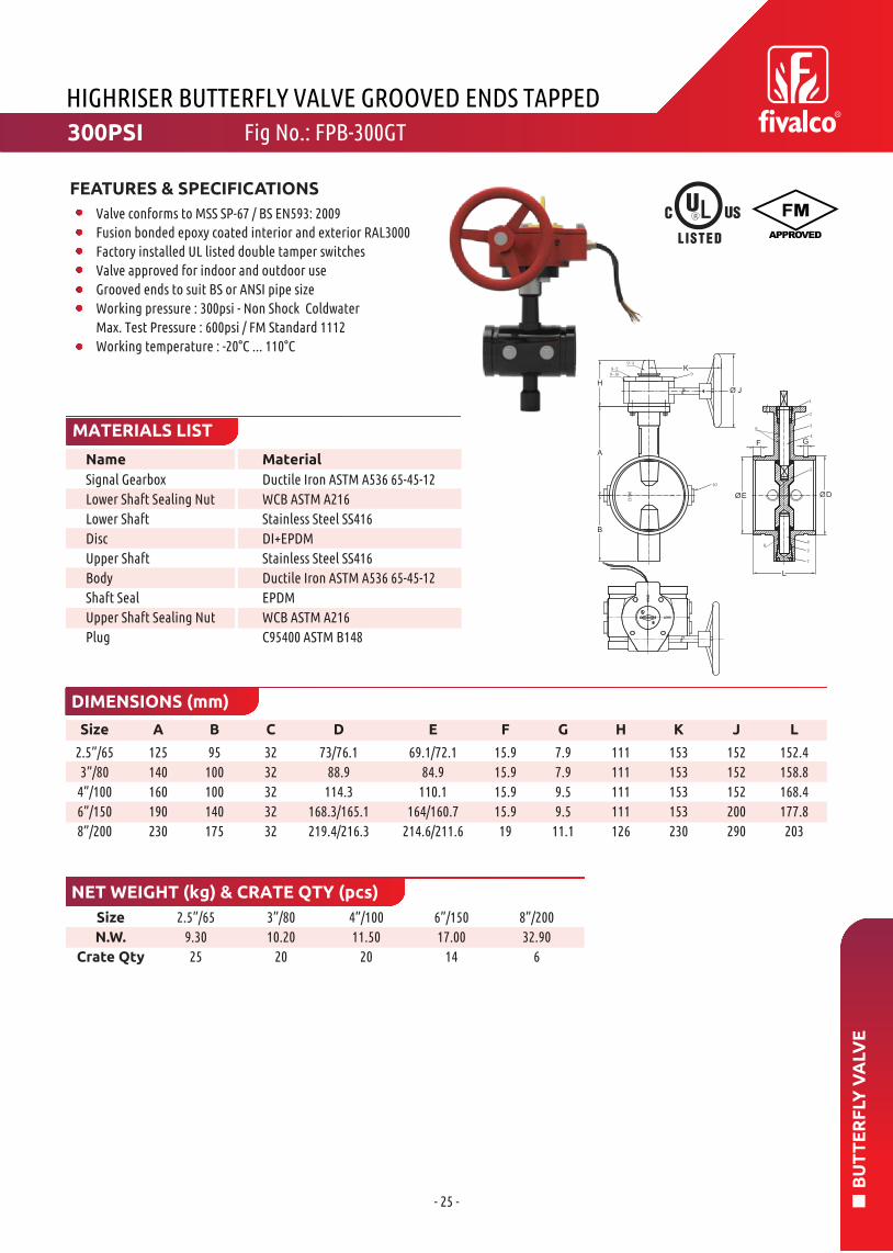
Size A B C D E F G H K J L
GF
Name Material
HIGHRISER BUTTERFLY VALVE GROOVED ENDS TAPPED
MATERIALS LIST
DIMENSIONS (mm)
NET WEIGHT (kg) & CRATE QTY (pcs)
Signal Gearbox
Lower Shaft Sealing Nut
Lower Shaft
Disc
Upper Shaft
Body
Shaft Seal
Upper Shaft Sealing Nut
Plug
2.5”/65
3”/80
4”/100
6”/150
8”/200
Size
N.W.
Crate Qty
2.5”/65
9.30
25
3”/80
10.20
20
4”/100
11.50
20
6”/150
17.00
14
8”/200
32.90
6
125
140
160
190
230
95
100
100
140
175
32
32
32
32
32
73/76.1
88.9
114.3
168.3/165.1
219.4/216.3
69.1/72.1
84.9
110.1
164/160.7
214.6/211.6
15.9
15.9
15.9
15.9
19
7.9
7.9
9.5
9.5
11.1
111
111
111
111
126
153
153
153
153
230
152
152
152
200
290
152.4
158.8
168.4
177.8
203
Ductile Iron ASTM A536 65-45-12
WCB ASTM A216
Stainless Steel SS416
DI+EPDM
Stainless Steel SS416
Ductile Iron ASTM A536 65-45-12
EPDM
WCB ASTM A216
C95400 ASTM B148
300PSI Fig No.: FPB-300GT
FEATURES & SPECIFICATIONS
Valve conforms to MSS SP-67 / BS EN593: 2009
Fusion bonded epoxy coated interior and exterior RAL3000
Factory installed UL listed double tamper switches
Valve approved for indoor and outdoor use
Grooved ends to suit BS or ANSI pipe size
Working pressure : 300psi - Non Shock Coldwater
Max. Test Pressure : 600psi / FM Standard 1112
Working temperature : -20°C ... 110°C

- 26 -
BU
TT
ER
FLY
VA
LVE
Name Material
FIREFLY BRONZE BUTTERFLY VALVE GROOVED ENDS
118±3
NC
B
SIZE300 CWP
MATERIALS LIST
DIMENSIONS (mm)
NET WEIGHT (kg) & CRATE QTY (pcs)
Body
Disc
Handwheel
Seat
Indicator
Housing
Size
B
C
ØE
ØF
M
N
Size
N.W.
Crate Qty
1.25”/32
138.9
98
42.4
38.99
15.88
7.95
1.25”/32
1.80
6
1.5”/40
1.87
6
2”/50
2.17
6
2.5”/65
2.80
6
1.5”/40
145.9
102
48.3
45.09
15.88
7.95
2”/50
159
104
60.3
57.15
15.88
7.95
2.5”/65
175.5
114
73
69.09
15.88
7.95
Bronze C836000
Stainless Steel AISI304
WCB
Viton
Powder Metal
Forged Brass
300PSI Fig No.: BBG-300
FEATURES & SPECIFICATIONS
Factory installed UL listed double tamper switches
Valve approved for indoor and outdoor use
Grooved ends to suit BS or ANSI pipe size
Working pressure : 300psi
Max. Test Pressure : 600psi
Max. working temperature : 250°F (120°C)

- 27 -
BU
TT
ER
FLY
VA
LVE
Name Material
FIREFLY BRONZE BUTTERFLY VALVE THREADED ENDS
118±3
SIZE
300 CWP
F C
MATERIALS LIST
DIMENSIONS (mm)
NET WEIGHT (kg) & CRATE QTY (pcs)
Body
Disc
Handwheel
Seat
Indicator
Housing
Size
B
C
E
F
Size
N.W.
Crate Qty
1”/25
129
54
39.7
44.5
1”/25
1.55
6
1.25”/32
1.71
6
1.5”/40
1.83
6
2”/50
2.35
6
2.5”/65
3.38
6
1.25”/32
137.9
66.7
49.2
55
1.5”/40
145.9
73
55.6
60.3
2”/50
159.8
82.6
70
79
2.5”/65
175.5
114
86.5
96
Bronze C836000
Stainless Steel AISI304
WCB
Viton
Powder Metal
Forged Brass
300PSI Fig No.: BBT-300
FEATURES & SPECIFICATIONS
Factory installed UL listed double tamper switches
Valve approved for indoor and outdoor use
Threaded : NPT or BSPT
Working pressure : 300psi
Max. Test Pressure : 600psi
Max. working temperature : 250°F (120°C)

- 28 -
BU
TT
ER
FLY
VA
LVE
Name Material EN Spec.
BS BUTTERFLY VALVE GROOVED ENDS
50
4-ØD
ØP
MATERIALS LIST
DIMENSIONS (mm)
NET WEIGHT (kg) & CRATE QTY (pcs)
Body
Shaft
Disc
Bushing
O-Ring
Size
A
B
C1
C2
Pipe OD
E
F
G
H
L
P
Size
N.W.
Crate Qty
2”/50
100.5
62
201.5
261.5
60.3
147
50
71.5
109
81
70
2”/50
6.50
100
2.5”/65
7.00
100
3”/80
7.50
80
4”/100
7.50
80
5”/125
14.00
42
6”/150
16.00
42
8”/200
20.00
30
10”/250
32.00
14
12”/300
48.00
14
2.5”/65
107
73/75
208
268
73/76.1
147
50
71.5
109
96
70
3”/80
114.5
81
215.5
275.5
88.9
147
50
71.5
109
96
70
4”/100
135
97
236
296
114.3
147
59
71.5
109
116
70
5”/125
148.5
114
249.5
309.5
141.3/139.7
147
72
71.5
109
147.6
70
6”/150
169
129
270
330
168.3/165.1
147
85.5
71.5
145
148
70
8”/200
198
159
299
359
219.1
47
112
71.5
145
135
70
10”/250
228.5
191
329.5
389.5
273
197
138
75
166
159
102
12”/300
266
222
367
427
323.9
197
164
75
166
165
102
Ductile Iron
Stainless Steel
EPDM Coated DI
NBR Coated DI
PTFE
EPDM/NBR
EN-JS1050
BS970 420S37
EN-JS1050
EN-JS1050
Commercial
Commercial
300PSI Fig No.: 1352
FEATURES & SPECIFICATIONS
Valve complies with EN593 / BS5155 / MSS SP-67
Top flange complies with ISO5211/1End-to-end dimensions according to MSS SP-67-2002
Grooved dimensions comply with Metric or ANSI pipe standards
Gear operator with two internal CE approved switches
Working pressure : 300psi
Working temperature : -10°C ... 100°C for EPDM coated discWorking temperature : -10°C ... 82°C for NBR coated disc

- 29 -
BU
TT
ER
FLY
VA
LVE
Name Material EN Spec.
BS BUTTERFLY VALVE WAFER TYPE
4-ØD
ØL
MATERIALS LIST
DIMENSIONS (mm)
NET WEIGHT (kg) & CRATE QTY (pcs)
Body
Shaft
Disc
Bushing
O-Ring
Size
A
B
C
D1
D2
E
F
G
H
L
4-ØD
Size
N.W.
Crate Qty
2”/50
132.5
78
43
233.5
293.5
147
53
71.5
109
70
6
2”/50
7.00
100
2.5”/65
7.30
100
3”/80
8.30
80
4”/100
11.00
80
5”/125
12.50
50
6”/150
14.00
50
8”/200
22.00
24
10”/250
29.00
20
12”/300
36.00
20
2.5”/65
145
85
46
246
306
147
63
71.5
109
70
6
3”/80
154.5
93
46
255.5
315.5
147
74
71.5
109
70
6
4”/100
179
112
52
280
340
147
77.5
71.5
109
70
6
5”/125
191.5
130
56
292.5
352.5
147
93
71.5
109
70
6
6”/150
213.5
146
56
314.5
374.5
147
107
71.5
145
70
8
8”/200
250.5
175
60
351.5
411.5
147
134
71.5
145
70
8
10”/250
282.5
210
68
383.5
443.5
197
162
75
166
102
10
12”/300
325.5
247
78
426.5
486.5
197
185
75
166
102
10
Ductile Iron
Stainless Steel
EPDM Coated DI
NBR Coated DI
PTFE
EPDM/NBR
EN-JS1050
BS970 420S37
EN-JS1050
EN-JS1050
Commercial
Commercial
Fig No.: 1353300PSI
FEATURES & SPECIFICATIONS
Valve complies with EN593 / BS5155 / MSS SP-67
Top flange complies with ISO5211/1End-to-end dimensions according to MSS SP-67-2002
Flange drilled to BS EN 1092-2 PN16 / ANSI B16.1 Class125
Gear operator with two internal CE approved switches
Working pressure : 300psi
Working temperature : -10°C ... 100°C for EPDM coated discWorking temperature : -10°C ... 82°C for NBR coated disc

- 30 -
GA
TE
VA
LVE
Name Material
FIRERISER GATE VALVE BS5163 NRS TYPE A
MATERIALS LIST
NET WEIGHT (kg) & CRATE QTY (pcs)
DIMENSIONS (inch/mm)
Body
Wedge Disc
Stem Nut
Stem
Bonnet
Gland
Dust Cap
Indicator
Indicator Plate
Handwheel
O-Ring
O-Ring(Cover)
Gland Ring
Spacer
O-Ring
Size
L
H
D
Size
N.W.
Crate Qty
2”/50
26.00
9
2.5”/65
27.00
9
3”/80
30.00
9
4”/100
39.00
9
5”/125
48.00
9
6”/150
56.00
9
8”/200
90.00
9
10”/250
130.00
4
12”/300
182.00
2
14”/350
232.00
1
16”/400
308.00
1
18”/450
446.00
1
20”/500
616.00
1
24”/600
848.00
1
2”/50
7.00/178
8.27/210
6.30/160
2.5”/65
7.48/190
9.33/237
7.87/200
3”/80
8.00/203
9.72/247
7.87/200
4”/100
9.00/229
11.81/300
7.87/200
5”/125
10.00/254
14.33/364
9.84/250
6”/150
10.50/267
15.90/404
9.84/250
8”/200
11.50/292
19.57/497
12.60/320
10”/250
13.00/330
23.23/590
14.57/370
12”/300
14.00/358
26.26/667
14.57/370
14”/350
13.78/381
34.72/882
17.72/450
16”/400
15.98/406
37.64/956
17.72/450
18”/450
17.00/432
40.43/1027
25.20/640
20”/500
17.99/457
43.54/1106
24.20/640
24”/600
20.00/508
49.53/1258
25.20/640
Ductile Iron ASTM A536 65-45-12
EPDM NBR
Brass
SS420
Ductile Iron ASTM A536 65-45-12
Ductile Iron ASTM A536 65-45-12
EPDM NBR
SS304
SS304
Ductile Iron ASTM A536 65-45-12
EPDM NBR
EPDM NBR
EPDM NBR
PTFE
EPDM NBR
Fig No.: BSGV3243 IND300PSI/235PSI
FEATURES & SPECIFICATIONS
Valve complies with BS5163 Type A
Fusion bonded epoxy coated RAL3000 with open shut indicator
Flange drilled to ANSI B16.1 Class 125 / ANSI B16.5 Class 150
Handwheel operator
Working pressure :
DN50 - DN300 : 300psi
DN350 - DN600 : 235psi
Working temperature : -10°C ... 120°C

- 31 -
ST
RA
INE
R
Size Measured Loss atIn/mm 15 fps (4.6m/s)
PLUG 3/4"
Name Material
HIGHRISER Y STRAINER FLANGED ENDS
MATERIALS LIST
NET WEIGHT (kg) & CRATE QTY (pcs)
DIMENSIONS (inch/mm)
Body
Cover
Screen
Gasket
Plug
2”/50
2.5”/65
3”/80
4”/100
5”/125
6”/150
8”/200
10”/250
12”/300
2”/50
7.99/203
5.20/132
7.68/195
2”/50
7.55
90
2.5”/65
13.05
50
3”/80
17.00
40
4”/100
26.00
32
5”/125
32.00
16
6”/150
55.60
12
8”/200
93.60
6
10”/250
132.00
2
12”/300
206.00
2
2.5”/65
10.00/254
6.22/158
9.45/240
3”/80
10.24/260
6.89/175
10.63/270
4”/100
12.13/308
7.99/202
12.60/320
5”/125
15.67/398
11.42/290
16.73/425
6”/150
18.58/472
13.15/334
19.49/495
8”/200
21.65/550
15.39/391
22.44/570
10”/250
25.75/654
18.11/460
27.56/700
12”/300
30.00/762
23.23/590
33.07/840
Size
N.W.
Crate Qty
Size
L
H
H1
7.22 psi
5.89 psi
8.24 psi
5.88 psi
7.63 psi
4.82 psi
5.83 psi
7.25 psi
5.73 psi
Ductile Iron A536 65-45-12
Ductile Iron A536 65-45-12
Stainless Steel AISI 304
EPDM
Carbon Steel
300PSI Fig No.: YS-300-FF
FEATURES & SPECIFICATIONS
Fusion bonded epoxy coated RAL3002
Flange drilled to ANSI B16.1 Class 125 / ANSI B16.5 Class 150 /
EN1092-2 PN16 / BS10 Table D / Table E
Working pressure : 300psi
Working temperature : -10°C ... 120°C

- 32 -
ST
RA
INE
R
PLUG 3/4"
Size Measured Loss atIn/mm 15 fps (4.6m/s)
Name Material
HIGHRISER Y STRAINER FLANGED-GROOVED ENDS
MATERIALS LIST
NET WEIGHT (kg) & CRATE QTY (pcs)
DIMENSIONS (inch/mm)
Body
Cover
Screen
Gasket
Plug
2”/50
2.5”/65
3”/80
4”/100
5”/125
6”/150
8”/200
10”/250
12”/300
2”/50
7.99/203
5.20/130
7.68/195
2.37/60.3
2.5”/65
10.00/254
6.22/158
9.45/240
2.87/73.0 3/76.1
3”/80
10.24/260
6.69/175
10.63/270
3.50/88.9
4”/100
12.13/308
7.95/202
12.60/320
4.50/114.3
5”/125
15.67/398
11.42/290
16.73/425
5.56/141.3 5.5/139.7
6”/150
18.58/472
13.15/334
19.49/495
6.63/168.3 6.5/165.1
8”/200
21.65/550
15.39/391
22.44/570
8.63/219.1
10”/250
25.75/654
18.11/460
27.56/700
10.75/273
12”/300
30.00/762
23.23/590
33.07/840
12.75/323.9
Size
L
H
H1
OD
Size
N.W.
Crate Qty
2”/50
7.55
90
2.5”/65
13.05
50
3”/80
17.00
40
4”/100
26.00
32
5”/125
32.00
16
6”/150
55.60
12
8”/200
93.60
6
10”/250
132.00
2
12”/300
206.00
2
7.22 psi
5.89 psi
8.24 psi
5.88 psi
7.63 psi
4.82 psi
5.83 psi
7.25 psi
5.73 psi
Ductile Iron A536 65-45-12
Ductile Iron A536 65-45-12
Stainless Steel AISI 304
EPDM
Carbon Steel
300PSI Fig No.: YS-300-FG
FEATURES & SPECIFICATIONS
Fusion bonded epoxy coated RAL3002
Flange drilled to ANSI B16.1 Class 125 / ANSI B16.5 Class 150 /
EN1092-2 PN16 / BS10 Table D / Table E / AWWA C606
Grooved ends to suit ANSI or BS standard pipe
Working pressure : 300psi
Working temperature : -10°C ... 120°C

- 33 -
ST
RA
INE
R
PLUG 3/4"
Name Material
Size Measured Loss atIn/mm 15 fps (4.6m/s)
HIGHRISER Y STRAINER GROOVED ENDS
MATERIALS LIST
NET WEIGHT (kg) & CRATE QTY (pcs)
DIMENSIONS (inch/mm)
Body
Cover
Screen
Gasket
Plug
2”/50
2.5”/65
3”/80
4”/100
5”/125
6”/150
8”/200
10”/250
12”/300
2”/50
7.99/203
5.20/130
7.68/195
2.37/60.3
2.5”/65
10.00/254
6.22/158
9.45/240
2.87/73.0 3/76.1
3”/80
10.24/260
6.69/175
10.63/270
3.50/88.9
4”/100
12.13/308
7.95/202
12.60/320
4.50/114.3
5”/125
15.67/398
11.42/290
16.73/425
5.56/141.3 5.5/139.7
6”/150
18.58/472
13.15/334
19.49/495
6.63/168.3 6.5/165.1
8”/200
21.65/550
15.39/391
22.44/570
8.63/219.1
10”/250
25.75/654
18.11/460
27.56/700
10.75/273
12”/300
30.00/762
23.23/590
33.07/840
12.75/323.9
Size
L
H
H1
OD
Size
N.W.
Crate Qty
2”/50
7.55
90
2.5”/65
13.05
50
3”/80
17.00
40
4”/100
26.00
32
5”/125
32.00
16
6”/150
55.60
12
8”/200
93.60
6
10”/250
132.00
2
12”/300
206.00
2
7.22 psi
5.89 psi
8.24 psi
5.88 psi
7.63 psi
4.82 psi
5.83 psi
7.25 psi
5.73 psi
Ductile Iron A536 65-45-12
Ductile Iron A536 65-45-12
Stainless Steel AISI 304
EPDM
Carbon Steel
300PSI Fig No.: YS-300-GG
FEATURES & SPECIFICATIONS
Fusion bonded epoxy coated RAL3002
Grooved ends to suit ANSI or BS standard pipe
Working pressure : 300psi
Working temperature : -10°C ... 120°C

- 34 -
AIR
VE
NT
Name Material
OUTLET
INLET
140
Ø134
Size Female Threaded
Size N.W. Crate Qty
AUTOMATIC AIR VENT VALVE THREADED ENDS
MATERIALS LIST
DIMENSIONS (inch/mm)
NET WEIGHT (kg) & CRATE QTY (pcs)
Body
Cover
Level
Seat Ring
Float
Float Arm
Orifice Button
½”/15
¾”/20
1”/25
½” - 1” 2.9 300
½” BSPT or NPT
¾” BSPT or NPT
1” BSPT or NPT
Ductile Iron A536 65-45-12
Ductile Iron A536 65-45-12
Stainless Steel AISI 304
Stainless Steel
Stainless Steel AISI 304
Stainless Steel AISI 304
Viton
200PSI Fig No.: 9702
FEATURES & SPECIFICATIONS
Threaded ends : NPT or BSPT
Working pressure : 200psi
Working temperature : -10°C ... 120°C

- 35 -
HY
DR
AN
T
Name Material
Bury Depths 3'-0" 3'-6" 4'-0" 4'-6" 5'-0" 5'-6" 6'-0"
Valve complies with AWWA C502Working pressure : 250psiWorking temperature : 0.6°C ... 52°C
CONSTRUCTION
Seating type is resilient material to bronze seal constructionOne pumper nozzle, 4.5-4NH threaded. Two hose nozzles, 2.5-7.5NHthread, other size threads are available6” mechanical joint designed to ANSI / AWWA C153 / A21.53 /Flanged to ANSI B16.1 Class125 / ANSI B16.5 Class150 / EN 1092-2 PN16
FIRERISER DRY BARREL FIRE HYDRANT
FEATURES
MATERIALS LIST
BURY DEPTH
Operating Nut
Hold Down Nut
O-Ring
Bonnet
Bonnet Bolt & Nut
Upper Rod
Pumper Nozzle
Pumper Nozzle Gasket
Hose Nozzle
Hose Nozzle Gasket
Pumper Nozzle Cap
Hose Nozzle Cap
Cap Chain
Standpipe Upper
Safety Coupling
Safety Flange Bolt & Nut
Safety Flange
Lower Rod
Standpipe Lower
Stem Pin
Drain Ring Housing
Drain Ring
Seat Ring
Bottom Plate
Disc Ring
Bottom Plate Nut
Elbow
Bronze ASTM B62
Bronze ASTM B62
NBR
Ductile Iron A536-65-45-12
Stainless Steel AISI 201
Carbon Steel AISI 1045
Bronze ASTM B62
NBR
Bronze ASTM B62
NBR
Ductile Iron A536-65-45-12
Ductile Iron A536-65-45-12
Carbon Steel Plated
Ductile Iron A536-65-45-12
Stainless Steel A890
Stainless Steel AISI 201
Ductile Iron A536-65-45-12
Carbon Steel AISI 1045
Ductile Iron A536-65-45-12
Stainless Steel A276
Ductile Iron A536-65-45-12
Bronze ASTM B62
Bronze ASTM B62
Ductile Iron A536-65-45-12
NBR
Ductile Iron A536-65-45-12
Ductile Iron A536-65-45-12
Fig No.: DBH2013-114(Flanged) / DBH2012-114(MJ)250PSI
- 36 -
HY
DR
AN
T
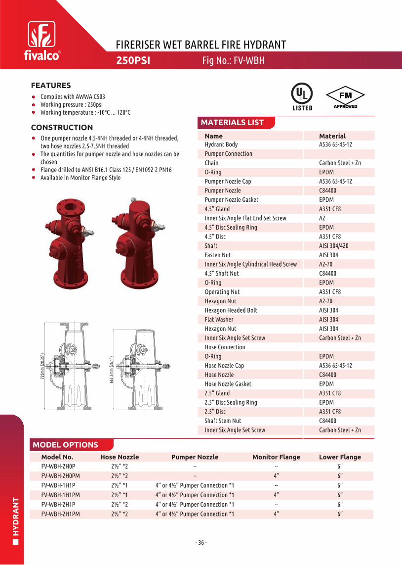
FIRERISER WET BARREL FIRE HYDRANT
Model No.
FV-WBH-2H0P
FV-WBH-2H0PM
FV-WBH-1H1P
FV-WBH-1H1PM
FV-WBH-2H1P
FV-WBH-2H1PM
Hose Nozzle
2½” *2
2½” *2
2½” *1
2½” *1
2½” *2
2½” *2
Pumper Nozzle
--
--
4” or 4½” Pumper Connection *1
4” or 4½” Pumper Connection *1
4” or 4½” Pumper Connection *1
4” or 4½” Pumper Connection *1
Monitor Flange
--
4”
--
4”
--
4”
Lower Flange
6”
6”
6”
6”
6”
6”
MODEL OPTIONS
Name Material
Complies with AWWA C503Working pressure : 250psiWorking temperature : -10°C ... 120°C
CONSTRUCTION
One pumper nozzle 4.5-4NH threaded or 4-4NH threaded,two hose nozzles 2.5-7.5NH threadedThe quantities for pumper nozzle and hose nozzles can bechosenFlange drilled to ANSI B16.1 Class 125 / EN1092-2 PN16Available in Monitor Flange Style
FEATURES
MATERIALS LIST
Hydrant Body
Pumper Connection
Chain
O-Ring
Pumper Nozzle Cap
Pumper Nozzle
Pumper Nozzle Gasket
4.5” Gland
Inner Six Angle Flat End Set Screw
4.5” Disc Sealing Ring
4.5” Disc
Shaft
Fasten Nut
Inner Six Angle Cylindrical Head Screw
4.5” Shaft Nut
O-Ring
Operating Nut
Hexagon Nut
Hexagon Headed Bolt
Flat Washer
Hexagon Nut
Inner Six Angle Set Screw
Hose Connection
O-Ring
Hose Nozzle Cap
Hose Nozzle
Hose Nozzle Gasket
2.5” Gland
2.5” Disc Sealing Ring
2.5” Disc
Shaft Stem Nut
Inner Six Angle Set Screw
A536 65-45-12
Carbon Steel + Zn
EPDM
A536 65-45-12
C84400
EPDM
A351 CF8
A2
EPDM
A351 CF8
AISI 304/420
AISI 304
A2-70
C84400
EPDM
A351 CF8
A2-70
AISI 304
AISI 304
AISI 304
Carbon Steel + Zn
EPDM
A536 65-45-12
C84400
EPDM
A351 CF8
EPDM
A351 CF8
C84400
Carbon Steel + Zn
720m
m (2
8.35
")
662.
5mm
(26.
1")
Fig No.: FV-WBH250PSI

GA
TE
VA
LVE
Saving lives and properties

- 37 -
GA
TE
VA
LVE
Name MaterialNo.
Size A±3 B±3 L±0.5 D W±3 Size N.W. Crate Qty
FIREFLY BRONZE OS&Y GATE VALVE THREADED ENDS
MATERIALS LIST
NET WEIGHT (kg) & CRATE QTY (pcs)DIMENSIONS (mm)
1
2
3
4
5
6
7
8
9
10
11
0.75”/20
1”/25
1.25”/32
1.5”/40
2”/50
173
196.5
220.5
243
282
145.5
163
181.5
197
227
59
69
75
82
90.5
20
25
32
37.5
50
80
80
80
100
120
0.75”/20
1”/25
1.25”/32
1.5”/40
2”/50
1.40
1.80
2.48
3.24
4.73
18
16
12
8
6
Body
Bonnet
Stem
Handwheel
Packing Gland
Disc
Disc Pin
Gland Packing
Stud
Yoke Bushing
Set Screw
Bronze ASTM C83600
Bronze ASTM C83600
Brass
Cast Iron
Bronze ASTM C83600
Bronze ASTM C83600
SS304
Graphite
Steel
Brass
Steel
175PSI Fig No.: BGV
FEATURES & SPECIFICATIONS
Threaded ends : NPT or BSPT
Working pressure : 175psi

- 38 -
GA
TE
VA
LVE
No. Name Material
Size A B C ØD L ØW
2"/50 184.5 168.5 58.8 38 46 99
Size N.W. Crate Qty
2"/50 1.82 12
FIREFLY BRONZE ANGLE VALVE THREADED ENDS
MATERIALS LIST
NET WEIGHT (kg) & CRATE QTY (pcs)DIMENSIONS (mm)
1
2
3
4
5
6
7
8
9
10
11
12
13
Body
Bonnet
Stem
Handwheel
Disc Holder
Seat
Packing Nut
Gland Packing
Lock Nut
Wheel Nut
Washer
Name Plate
Disc Nut
Bronze ASTM C84400
Forged Brass
Brass
Cast Iron
Forged Brass
BUNA-N
Brass
PTFE
Brass
Steel
Brass
Aluminum
Brass
300PSI Fig No.: BAV
FEATURES & SPECIFICATIONS
Threaded ends : NPT or BSPT
Working pressure : 300psi

- 39 -
GL
OB
E V
ALV
E
No. Name Material
FIREFLY BRONZE GLOBE VALVE THREADED ENDS
MATERIALS LIST
NET WEIGHT (kg) & CRATE QTY (pcs)
DIMENSIONS (mm)
1
2
3
4
5
6
7
8
9
10
11
12
13
Size
A
B
L
ØW
ØD
Size
N.W.
Crate Qty
0.5”/15
99
90.5
54.7
58
13.5
0.5”/15
0.32
80
0.75”/20
0.41
60
1”/25
0.82
30
1.25”/32
1.19
24
1.5”/40
1.50
18
2”/50
2.30
12
0.75”/20
103
98
60.5
58
16.5
1”/25
130
119
77
74
23
1.25”/32
166
151.5
91.8
78.5
28
1.5”/40
181
165
101.5
78.5
34
2”/50
219
200
116.5
99
45
Body
Bonnet
Stem
Handwheel
Disc Holder
Seat
Packing Nut
Gland Packing
Lock Nut
Wheel Nut
Washer(1½”~2”)
Name Plate
Disc Nut(1½”~2”)
Bronze C84400
Brass C37700(¼”~¾”)
Bronze C84400(1”~2”)
Brass
Cast Iron
Brass(¼”~1¼”)
Forged Brass(1½”~2”)
BUNA-N
Brass
PTFE
Brass
Steel
Brass
Aluminum
Brass
175PSI Fig No.: BGVT
FEATURES & SPECIFICATIONS
Threaded ends : NPT or BSPT
Working pressure : 175psi
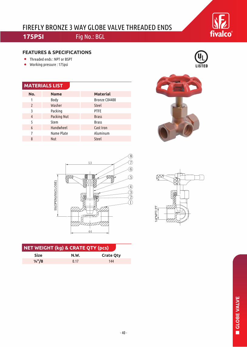
- 40 -
GL
OB
E V
ALV
E
Size N.W. Crate Qty
¼"/8 0.17 144
FIREFLY BRONZE 3 WAY GLOBE VALVE THREADED ENDS
Name MaterialNo.
MATERIALS LIST
NET WEIGHT (kg) & CRATE QTY (pcs)
1
2
3
4
5
6
7
8
Body
Washer
Packing
Packing Nut
Stem
Handwheel
Name Plate
Nut
Bronze C84400
Steel
PTFE
Brass
Brass
Cast Iron
Aluminum
Steel
175PSI Fig No.: BGL
FEATURES & SPECIFICATIONS
Threaded ends : NPT or BSPT
Working pressure : 175psi

- 41 -
FIR
E H
OS
E V
ALV
E
DET QTY Name Material
FIREFLY BRASS FIRE HOSE VALVE
MATERIALS LIST
NET WEIGHT (kg) & CRATE QTY (pcs)DIMENSIONS (mm)
1
2
3
4
5
6
7
8
9
10
11
12
13
A±2
161.5
222
B±2
188
270.5
C±0.5
49.5
70
D±0.5
58
79
E
90
128
1.5”/40
1.75
12
2.5”/65
4.03
4
Size
1.5”/40
2.5”/65
Size
N.W.
Crate Qty
1
1
1
1
1
1
1
1
1
1
1
2
1
Body
Bonnet
Stem
Disc Holder
Disc Nut
Packing Nut
Handwheel
Seat
Nut
Clamping Ring
Name Plate
O-Ring
O-Ring
Brass ASTM B584
Brass ASTM B584
Brass
Forged Brass
Brass
Brass
Ductile Iron
NBR
Stainless Steel
Forged Brass
Aluminum
NBR
NBR
Fig No.: BHVFF300PSI
FEATURES & SPECIFICATIONS
Inlet : Female NPT
Outlet : Female NPT
Working pressure : 300psi
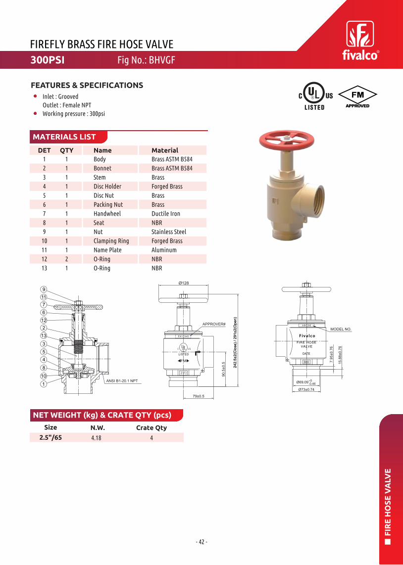
- 42 -
FIR
E H
OS
E V
ALV
E
DET QTY Name Material
Size N.W. Crate Qty
2.5"/65 4.18 4
FIREFLY BRASS FIRE HOSE VALVE
MATERIALS LIST
NET WEIGHT (kg) & CRATE QTY (pcs)
1
2
3
4
5
6
7
8
9
10
11
12
13
1
1
1
1
1
1
1
1
1
1
1
2
1
Body
Bonnet
Stem
Disc Holder
Disc Nut
Packing Nut
Handwheel
Seat
Nut
Clamping Ring
Name Plate
O-Ring
O-Ring
Brass ASTM B584
Brass ASTM B584
Brass
Forged Brass
Brass
Brass
Ductile Iron
NBR
Stainless Steel
Forged Brass
Aluminum
NBR
NBR
Fig No.: BHVGF300PSI
FEATURES & SPECIFICATIONS
Inlet : Grooved
Outlet : Female NPT
Working pressure : 300psi

- 43 -
FIR
E H
OS
E V
ALV
E
DET QTY Name Material
FIREFLY BRASS FIRE HOSE VALVE
MATERIALS LIST
NET WEIGHT (kg) & CRATE QTY (pcs)
DIMENSIONS (mm)
1
2
3
4
5
6
7
8
9
10
11
12
13
A±2
161.5
222
B±2
188
270.5
C±0.5
49.5
70
D±0.5
58
79
E
90
128
Size
1.5”/40
2.5”/65
1.5”/40
1.82
12
2.5”/65
4.03
4
Size
N.W.
Crate Qty
1
1
1
1
1
1
1
1
1
1
1
2
1
Body
Bonnet
Stem
Disc Holder
Disc Nut
Packing Nut
Handwheel
Seat
Nut
Clamping Ring
Name Plate
O-Ring
O-Ring
Brass ASTM B584
Brass ASTM B584
Brass
Forged Brass
Brass
Brass
Ductile Iron
NBR
Stainless Steel
Forged Brass
Aluminum
NBR
NBR
300PSI Fig No.: BHVFM
FEATURES & SPECIFICATIONS
Inlet : Female NPT
Outlet : Male NST
Working pressure : 300psi

- 44 -
FIR
E H
OS
E V
ALV
E
DET QTY Name Material
1
9
2
4
8
10
5
3
13
12
6
7
11
R
UL
2 1 2
C US
APPROVER#2
42
.5±2
(Clo
se
) /
29
1±2
(Op
en
)
90
.5±0
.5
79±0.5
Size N.W. Crate Qty
2.5"/65 4.18 4
FIREFLY BRASS FIRE HOSE VALVE
MATERIALS LIST
NET WEIGHT (kg) & CRATE QTY (pcs)
1
2
3
4
5
6
7
8
9
10
11
12
13
1
1
1
1
1
1
1
1
1
1
1
2
1
Body
Bonnet
Stem
Disc Holder
Disc Nut
Packing Nut
Handwheel
Seat
Nut
Clamping Ring
Name Plate
O-Ring
O-Ring
Brass ASTM B584
Brass ASTM B584
Brass
Forged Brass
Brass
Brass
Ductile Iron
NBR
Stainless Steel
Forged Brass
Aluminum
NBR
NBR
300PSI Fig No.: BHVGM
FEATURES & SPECIFICATIONS
Inlet : Grooved
Outlet : Male NST
Working pressure : 300psi

- 45 -
FLE
XIB
LE S
PR
INK
LER
CO
NN
ECTO
R
DET QTY Name Material
Rated Pressure : 200psiMaximum Ambient Temperature : 225(°F), 107(°C)Connection : DN25*DN15 or DN20 (1” x 1/2” or 3/4”), NPT or BSPTHose Diameter : O.D. 26.8mm / 11/15” Flow: 22.5mm / 7/8”Designed for use in Wet and Dry Systems
AssemblingLength
mm inch
In-&OutletHead Size
DN in.
Max. numberof 90° bends
Min bendingradius
n x 90° mm inch
Equivalent Length of DN25/1” Sch. 40 Pipe at C=120 in
QF-600 With straight discharge Nipple*
AssemblingLength
mm inch
In-&OutletHead Size
DN in.
Max. numberof 90° bends
Min bendingradius
n x 90° mm inch
Equivalent Length of DN25/1” Sch. 40 Pipe at C=120 in
QF-1000E With 90° elbow discharge
QF-1000With
FLEXIBLE SPRINKLER CONNECTOR
Results are tested & recorded by UL under minimum bending radius in maximum bending degrees.Results are tested & recorded by FM approvals under minimum bending radius in maximum bending degrees.
Note : 1. For QF-600, UL & ULC Listed2. For QF-1000, FM Approved, UL & ULC Listed
MAIN COMPONENTS & MATERIALS LIST
TECHNICAL DATA
1
2
3
4
5
6
7
8
9
10
70028
100040
120048
150060
180072
70028
100040
120048
150060
180072
70028
100040
120048
150060
180072
70028
100040
120048
150060
180072
25x151”x½”25x151”x½”25x151”x½”25x151”x½”25x151”x½”25x201”x¾”25x201”x¾”25x201”x¾”25x201”x¾”25x201”x¾”
25x151”x½”25x151”x½”25x151”x½”25x151”x½”25x151”x½”25x201”x¾”25x201”x¾”25x201”x¾”25x201”x¾”25x201”x¾”
1004
1004
1004
1004
1004
1004
1004
1004
1004
1004
5.51810331343
19.263
23.8787.324
12.5411446
19.564
24.480
1
2
2
3
4
1
2
2
3
4
25010
25010
25010
25010
25010
25010
25010
25010
25010
25010
8.126.712.942.616.253.220.667.825.182.46.5
21.512
39.515.751.619.363.522.975.4
826.512.440.815.450.420
65.724.6815.1
16.810.434.213.945.817
58.721.771.5
1
3
3
4
4
1
3
3
4
4
1
1
1
2
2
2
1
2
1
1 Set
Corrugated Tube
Discharge Nipple(Elbow)
Inlet Nipple
Hexagon Slip Nut
Gasket
Isolation Ring
Center Bracket
Side Bracket
Square Bar
Bolts & Screws
AISI 304 Stainless Steel
Galv. Steel ASTM 1020
Galv. Steel ASTM 1020
Galv. Steel ASTM 1020
EPDM
Nylon 66
Galv. Steel ASTM A283 Gr. D
Galv. Steel ASTM A283 Gr. D
Galv. Steel ASTM A283 Gr. B
Galv. Steel ASTM A283 Gr. D
Fig No.: QF-600 / QF-1000 / QF-1000E
QF-600 : Unbraided HoseQF-1000 : Braided HoseQF-1000E : Braided Hose With Elbow NippleAnchoring components are intended for use with drop ceilings conforming to ASTM C635 and other majorStandards when installed in accordance with the Standard Practice for installation Metal Ceiling Suspension Systems for Acoustical Tile and Lay-In Panels, ASTM C636 or other equivalent standards.
FEATURES & SPECIFICATIONS

- 46 -
FLE
XIB
LE S
PR
INK
LER
CO
NN
ECTO
R
A. Connect Inlet Nipple
B. Fix bracket set
C. Bending & Locating D. Connect Discharge Nipple
INSTALLATION INSTRUCTIONS
Use pipe wrench to screw the Inlet Nipple into the branch outlet interface on water supply pipeline, use pipe sealant (Teflon tape or pipe glue etc.) to seal and apply tightening torque of approx. 50N·m/35ft-lbs. Then tighten the Hexagon Slip Nut with 15N·m/10ft-lbs to ensure sealing performance.
Bend the Flexible Hose body as desired (According the parameters on Specification sheet) and locate the Discharge Nipple into the center bracket.Tighten the bolts on center bracket with 4N·m/3ft-lbs after the proper location of springkler head has been found.
Actual bending radius
EQUAL to GREATER than SMALLER than
Required minimum bending radius
Use Fivalco® bend snap-gauge for bending gradius inspection
FLEXIBLE SPRINKLER CONNECTOR
Tighten the Slip Nuts with 15N·m/10ft-lbs and install sprinkler head to Discharge Nipple by following the sprinkler manufacture’s installation instructions. Finally test leak in according with NFPA guidelines.
Attach side brackets to the main-rail of the T-bar grid and cross the square bar through 2 side brackets, with the center bracket in the middle. Tighten all fixing bolt on the side brackets with 4N·m/3ft-lbs.
Hose Length L W H QF-600 QF-1000 L W H Box Hose QF-600 QF-1000
mm mm mm mm ea kg kg mm mm mm ea ea kg kg
Carton box Pallet
SizeQty
Gross weight Size Quantity Gross weight
HOSE BENDING, CORRECT OR WRONG?
ASSEMBLY INSTRUCTIONS
CALCULATION OF BENDING DEGREES
1050
1300
1500
1800
2100
205
205
205
205
205
195
195
195
195
195
20
20
20
20
20
27.2
28.9
30.2
32
34
31.5
35.3
37.7
42
45.6
1050
1300
1500
1800
2100
1050
1050
1050
1050
1050
1125
1125
1125
1125
1125
25
25
25
25
25
500
500
500
500
500
700
745
780
830
885
805
905
970
1080
1175
700
1000
1200
1500
1800

- 47 -
INS
TA
LL
AT
ION
GU
IDE
INSTALLATION GUIDE
Design Requirements
Installation
Care&Maintenance
Fivalco grooved butterfly valve should be connected to the piping system with approved coupling or flange adapters. Flow may be from either direction, and the valve may be positioned in any direction.
Fivalco butterfly valves have been designed with a slow close handwheel operator which effectively minimizes water hammer. These valves feature minimum flow restriction and pressure loss when in the fully open position.
When the valves are received from the manufacture they should be handled carefully to avoid breakage anddamage to the seating area. Before installation of the valve, clean piping, flange and couping. When the valve closes hard, it is usually due to debris lodged in the sealing area. Often this may be corrected by backing off thehand wheel and closing again.
The valve should never be forced to seat by applying a wrench to the hand wheel as this may distort the valvecomponents or score the sealing surface. The use of excessive force to open or close the valve violates all warranties express or implied.
The inlet and outlet pipe adjacent to the valve should be properly supported to prevent excessive stress on thevalve body. The valve should not be used to force a pipeline into position as this may result in distortion of thevalve body.
Conduit and electrical connections to the optional tamper switch must be in accordance with National ElectricalCode(NFPA 72) and /or requirements of the local authority having jurisdiction.
Fivalco butterfly valves require no regular maintenance, however, it is advisable to inspect and verify properoperation of the unit annually or in accordance with the authority having jurisdiction. The inspection shouldinclude a visual check for leakage at the valve pipe connection and body to operator connection.
Inspection and maintenance should be performed by a qualified inspection service.

- 48 -
INS
TA
LL
AT
ION
GU
IDE
BUTTERFLY VALVE INSTALLATION GUIDE
Fivalco butterfly valves are provided with internal supervisory position switches. The tamper switch operates by a cam connected to the valve stem.
Switch Installation
SUPERVISORY SWITCH
FIRE ALARM CONTROL PANEL SUPERVISORY PANEL
YELLOW
COMMON
YELLOW
RED
RED
SWITCH
RED
YELLOW (COMMON)
S.P.S.T.N.C. SWITCHWITH DUAL LEADSSOLDERED TOSWITCH TABS(SWITCH SHOWN IN ‘FULL-OPEN’ POSITION)
AUXILIARY SWITCH
WHITECOMMON
WHITE (COMMON)GREEN
BLUESWITCH
BLUE
GREEN
BLACK
GROUND
TO AUXILIARY DEVICE
S.P.S.T.N.C. SWITCHWITH DUAL LEADSSOLDERED TOSWITCH TABS(SWITCH SHOWN IN ‘FULL-OPEN’ POSITION)
CONNECTION TO GROUNDSCREW INSIDE HOUSING
WIRING DIAGRAM
SUPERVISORYSWITCH
AUXILIARYSWITCH
ACTUATORCASE
GROUND
GREEN
BLACK(COM)
WHITE(COM)YELLOW×2-Valve Open
RED×2-Valve Not Open
BLUE×2-Valve Open
ORANGE×2-Valve Not Open

- 49 -
INS
TA
LL
AT
ION
GU
IDE
1. GENERAL
2. UNLOADING & TRANSPORTATION
5. INSTALLATION
Gate valves form a significant component of the piping systems. Failure of a gate valve in such systems, either due to faulty installation or improper maintenance, could result in extensive damage and costly repairs. In addition, many gate valves are installed in buried- service or underground applications. Problems with or malfunctions of the valves due to faulty installation or improper maintenance may result in extensive and costly unearthing operation to effectively correct or eliminate the problem. Many gate-valve problems and failure can be traced back to improper installation, operation, or maintenance procedures. Gate valves may not be installed and used as anchor points, and should at all times be kept free from stress arising from the system pipeline.
A vital consideration in handling valves should be avoid damaging or scratching the coating protection.
All valves should be unloaded carefully. Each valve should be carefully lowered from the truck to the ground; it should not be dropped. In the case of larger valves, forklifts or slings around the body of the valve or under the skids should be used for unloading. Only hoists and slings with adequate load capacity to handle the weight of the valve or valves should be used. Hoists should not be hooked into or chains fastened around yokes, stem, or handwheels. Failure to carefully follow these recommendations is likely to result in damage to the valve.
4. INSPECTION PRIOR TO INSTALLATION
Gate valves should be inspected at the time of receipt for damage in shipment. The initial inspection should be to verify compliance with specifications, direction of opening, and type of end connections. A visual inspection of the seating surfaces should be performed to detect any damage in shipment or scoring of the seating surfaces. Inspection personnel should look for bent stems, broken handwheels, cracked parts, loose bolt, missing parts and accessories, and any other evidence of mishandling during shipment. Each valve should be operated through one complete opening-and-closing cycle in the position in which it is to be installed.
3. STORAGE
Valves should be stored in the fully closed position to prevent the entry of foreign material that could cause damage to the seating surface. Whenever practical, valves should be stored indoors under dry, cool conditions, away from direct sunlight and corrosive or otherwise chemically active atmosphere. If outside storage is required, means should be provided to protect the operating mechanism from weather elements. During outside storage, valves should be protected from the weather, sunlight, ozone, and foreign materials. In colder climates where valves may be subject to freezing temperatures, it is absolutely essential to remove the water from the valve interior and close the valve before storage. Failure to do so many results in a cracked valve casting and or deterioration of the resilient seat material.
At the jobsite prior to installation, each valve should be visually inspected and any foreign material in the interior portion of the valve should be removed.
Before being installed, the valves need to be washed so as to eliminate the dust caused during the transportation and storage.
Valves can be installed at horizontal or vertical pipe line. When being installed, the medium flow direction should be same as the showing flowing direction on the valves.
During installation in the pipeline system, care must be taken to ensure that the connecting flanges of the pipeline getting in contact with the gate valve are arranged parallel to each other and are exactly aligned to avoid any tension loads acting upon the valve body.
Only hand can be used to open and close the valves, all of the other force from outside should not be used.
INSTALLATION, OPERATION AND MAINTENANCE OF RESILIENT-SEATED GATE VALVE

- 50 -
INS
TA
LL
AT
ION
GU
IDE
5.1 All bolts should be checked for proper tightness and protected by the installer to prevent corrosion, either with a suitable paint or by polyethylene wrapping.
5.2 Underground installation valves in water-distribution lines shall, where practical, be located in easily accessible areas.5.2.1 During installation there is the possibility of foreign materials inadvertently entering the valve. Foreign material can damage internal working parts during operation of the gate valve. For this reason, gate valves should be installed in the closed position. Each valve should be placed on firm footing in the trench to prevent setting and excessive strain on the connection to the pipe. Pipe systems should be supported and aligned to avoid damage to the valve.5.2.2 A valve box or vault should be provided for each valve used in a buried-service application. The valve box should be installed so as not to transmit shock loads or stress to the valve. The valve box should be centered over the operating nut of the valve with the box cover flush with the surface of the finished area or such other level as directed by the owner. Valve boxes should be of such design that a traffic load on the top of is not transmitted to the valve.5.2.3 Valves buried in unusually deep trenches should have special provisions for operating the valve - either a riser on the stem to permit use of a normal key or a notation on the valve records that a long key will be required.5.2.4 When valves with exposed gearing or operating mechanisms are installed belowground, a vault designed to allow pipe clearance and prevent setting on the pipe should be provided. The operating nut should be accessible from the top opening of the vault with a valve key. The size of the vault should provide for easy removal of the valve bonnet and internal parts of the valve for purpose of repair.Consideration should be given to the possible entry of groundwater and/or surface water and to the need to provide for the disposal of such water.
5.3 Aboveground Installation. Valves installed aboveground or in a plant piping system should be supported and aligned to avoid damage to the valves. Valves should not be used to correct the misalignment of piping.
5.4 After installation and before pressurization of the valve, all pressure-containing bolting (bonnet, seal plate, packing gland, and end connections) should be inspected for adequate tightness to prevent leakage. In addition, an inspection should be made for adequate tightness of all tapped and plugged connections to the valve interior. Proper inspection at this time will minimize the possibility of leaks after pressurization of the piping system.
5.5 In order to prevent time lost searching for leaks, it is recommended that the valve excavations are not backfilled until after until after pressure tests have been made. After installation, it is desirable to test newly installed piping sections, including valves, at some pressure above the system design pressure. The valve should not be operated in either the opening or closing direction at different pressures above the rated working pressure. It is also recognized that wear or foreign material may damage valve seating surfaces and may cause leakage.
5.6 On completion of the installation, valve location, size, make, type, date of installation, number of turns to open, direction of opening, and other information deemed pertinent should be entered on permanent records.
5.7 Application Hazards. Valves should not be installed in applications or for service other than the recommended for that purpose or approved in advance by the manufacture.5.7.1 Valves should not be installed in lines where service pressure will exceed the rated working pressure of the valve.5.7.2 Gate valves should not be used for throttling service unless the design is specially recommended for that purpose or approved in advance by the manufacture.5.7.3 Valves should not be used in applications that are exposed to freezing temperature unless sufficient flow is maintained through the valve or other protection is provided to prevent freezing.5.7.4 Gate valves should not be installed at a dead end or near a bend in a pipeline without proper and adequate restraint to support the valve and prevent it from blowing off the end of the line.5.7.5 To prevent damage, 4” and below size NPS resilient-seated gate valves should not be operated with input torques greater than 200ft-lb(270N.m). Gate valves 6” to 12” NPS should not be operated with input torques greater than 300ft-lb(406N.m). See table 1 & 2 for bolt tightening torques.

FIVALCO WARRANTY STATEMENT
Fivalco’s products are designed, engineered and manufactured within its specification of intended use, under the highest quality control possible. Commitment on quality and performance is always at the top of our agenda.
Fivalco warrants that for a period of thirty-six (36) months following delivery, the Fivalco products will perform in accordance with published specifications, and will be free from defects in material or workman-ship provided that the products are stored and installed in accordance with recommendations in our catalogues.
Fivalco’s obligation shall be to replace any product found to be defective in design, material or workmanship during the warranty period. Fivalco shall not be obligated to refund the purchase price and other liabilities on monetary compensation, nor shall it be obligated to pay for any labor or costs associated with the removal of the defective products or the reinstallation of those products. No warranty coverage will be provided for products that have been altered and / or used for a purpose other than that for which they were designed or installed contrary to Fivalco’s guidelines.

NO
TE
S
NOTES

NO
TE
S
NOTES

300PSI Fig No.: 3288-LI-300-FM
GA
TE
VA
LVE
FV-FPP-EN-20210630Fivalco® is Registered Trademark
Fivalco Limited | [email protected] | www.fivalco.com
Fivalco reserves the right to alter the information in this document without prior notice. Fivalco shall not be liable for technical errors or omissions contained herein.Refer to local sales representatives for detail catalogues, technical data and specifications.


![Fire Protection - SmartCockpit A319-320-321 [Fire Protection] Page 1. Airbus A319-320-321 [Fire Protection] ... [Fire Protection] Page 46. Airbus A319-320-321 [Fire Protection] Page](https://static.fdocuments.net/doc/165x107/5aaae6367f8b9a6c188ed0d4/fire-protection-a319-320-321-fire-protection-page-1-airbus-a319-320-321-fire.jpg)