Procidia iWare AlarmWorX32 - Siemens
68
Protection notice / Copyright notice Procidia iWare AlarmWorX32 AlarmWorX32 Server Configurator January 2010 © Siemens AG 2008. All rights reserved.
Transcript of Procidia iWare AlarmWorX32 - Siemens

Protection notice / Copyright notice
Procidia iWare AlarmWorX32AlarmWorX32 Server ConfiguratorJanuary 2010
© Siemens AG 2008. All rights reserved.

Industry Automation / Process Instrumentation & Analytics© Siemens AG 2008. All rights reserved.
January 2010 F. MoninoPage 2
Introduction / Contents
Procidia iWare is an operator interface software designed to support the 353 series controller.
AlarmWorX32 is a suite of applications within Procidia iWare that manages alarms and events.
This tutorial illustrates how to build the AlarmWorX32 Server database.
Sections
Overview 3
Project Management 13
Server Configurator 15
Alarm Server 58
Technical Support 68

Protection notice / Copyright notice
AlarmWorX32 Overview
© Siemens AG 2008. All rights reserved.

Industry Automation / Process Instrumentation & Analytics© Siemens AG 2008. All rights reserved.
January 2010 F. MoninoPage 4
AlarmWorX32 Overview
AlarmWorX32 Components
AlarmWorX32 Server ConfiguratorAlarmWorX32 Server
AlarmWorX32 ViewerGraphWorX32 ActiveX component
AlarmWorX32 Logger ConfiguratorAlarmWorX32 Logger
AlarmWorX32 ReportGraphWorX32 ActiveX component

Industry Automation / Process Instrumentation & Analytics© Siemens AG 2008. All rights reserved.
January 2010 F. MoninoPage 5
AlarmWorX32 Server Configurator
AlarmWorX32 Server Configurator utility builds the Alarm Management Configuration database.
The Alarm Management database defines alarm tags and alarm management criteria.

Industry Automation / Process Instrumentation & Analytics© Siemens AG 2008. All rights reserved.
January 2010 F. MoninoPage 6
AlarmWorX32 Server Configurator
Alarm TagsAn alarm tag is associated with an OPC tag.
An OPC server supports communications between the Procidia iWareproject and devices in the field.An OPC tag is a connection to a process variable.
Define the alarm type:DiscreteLimitDeviation
Alarm messages provide descriptive and informative text.

Industry Automation / Process Instrumentation & Analytics© Siemens AG 2008. All rights reserved.
January 2010 F. MoninoPage 7
AlarmWorX32 Server Configurator
Management CriteriaAcknowledgement criteria
Does the alarm message need to be acknowledged?
Severity levelSeverity level is a method to distinguish between critical alarms and process events
AreasAreas is a method to filter alarmsAn area is a logical grouping of alarm tags

Industry Automation / Process Instrumentation & Analytics© Siemens AG 2008. All rights reserved.
January 2010 F. MoninoPage 8
AlarmWorX32 Server
AlarmWorX32 Server runs in the background.The server does not have a graphical user interface (GUI).
The Alarm Server connects to the Alarm Management Configuration database.The Alarm Management configuration database contains one or more Alarm Server configurations.The Alarm Server runs only one configuration.The Alarm Server configuration contains the list of alarm tags to monitor.
In run-time, the Alarm Server connects to the OPC servers and polls OPC tags.Alarm tags are associated with OPC tags.The monitoring rate is configured in the AlarmWorX32 Server Configurator.Default rate is 1.0 seconds.

Industry Automation / Process Instrumentation & Analytics© Siemens AG 2008. All rights reserved.
January 2010 F. MoninoPage 9
AlarmWorX32 Server
The Alarm Server can poll both discrete and analog OPC tags.Discrete alarm type
The controller determines the alarm event.The Alarm Server reads the discrete state and determines if it is active.The discrete alarm type is recommended.
Analog alarm typesThe Server reads an analog value and determines the alarm status.Alarm types: Limit, Deviation, Change of Rate
The Alarm Server also manages alarm events.It provides the alarm tag and description.It manages the acknowledgement status of the event.It provides time stamps.

Industry Automation / Process Instrumentation & Analytics© Siemens AG 2008. All rights reserved.
January 2010 F. MoninoPage 10
AlarmWorX32 Viewer
The AlarmWorX32 Viewer is an ActiveX component that runs within GraphWorX32.
The Viewer connects to the AlarmWorX32 Server.
The Viewer displays active alarm events.Time stampAlarm tagAlarm descriptionAcknowledgement statusOther attributes
Attributes are properties of an Alarm Tag.Different alarm types have different attributes

Industry Automation / Process Instrumentation & Analytics© Siemens AG 2008. All rights reserved.
January 2010 F. MoninoPage 11
AlarmWorX32 Logger Configurator
The AlarmWorX32 Logger Configurator utility specifies the logging/printing criteria.
Alarm events can be logged to a database or sent to a printer.
Alarm attributes to be logged/printed are specified.
Logging databaseAlarm events can be saved to a Microsoft Access or SQL database.
PrinterOptionally, alarm events can be sent to a local printer.

Industry Automation / Process Instrumentation & Analytics© Siemens AG 2008. All rights reserved.
January 2010 F. MoninoPage 12
AlarmWorX32 Report
The AlarmWorX32 Report is an ActiveX component that runs within GraphWorX32.
The Alarm Report connects to the Alarm Logger database.
The Alarm Report displays a summary of alarm events.

Protection notice / Copyright notice
AlarmWorX32 Project Management
© Siemens AG 2008. All rights reserved.

Industry Automation / Process Instrumentation & Analytics© Siemens AG 2008. All rights reserved.
January 2010 F. MoninoPage 14
Database Management
The Procidia project is stored in the Procidia APPs folder.
Create a Server Database folder in Procidia APPs.
The Server Database folder organizes the project database configurations.
AlarmWorX32 Server configurationHistorical trend databaseSecurity Server configuration
Create Server Database folderin Procidia APPs

Protection notice / Copyright notice
AlarmWorX32 Server Configurator
© Siemens AG 2008. All rights reserved.

Industry Automation / Process Instrumentation & Analytics© Siemens AG 2008. All rights reserved.
January 2010 F. MoninoPage 16
Windows Programs Menu
Open AlarmWorX32 Server ConfiguratorClick Task Bar Start buttonSelect Programs/ SIEMENS Procidia/ iWare PC/
AlamWorX32/ AlarmWorX32 Server Configurator

Industry Automation / Process Instrumentation & Analytics© Siemens AG 2008. All rights reserved.
January 2010 F. MoninoPage 17
Configuration Database Wizard
Start a new Alarm Management Configuration database
Select Menu bar File/ New

Industry Automation / Process Instrumentation & Analytics© Siemens AG 2008. All rights reserved.
January 2010 F. MoninoPage 18
Configuration Database Wizard
Selecting File/ New opens the AlarmWorX32 Server Configuration Wizard.
The wizard helps to select and create the Alarm Management Configuration database file.
Start Configuration Database Wizard
Click Next button

Industry Automation / Process Instrumentation & Analytics© Siemens AG 2008. All rights reserved.
January 2010 F. MoninoPage 19
Configuration Database Wizard
The Alarm Management Configuration database can be either a Microsoft Access or SQL database.
Procidia iWare installs Microsoft Access drivers if not already installed.
The current version of iWare does not provide SQL drivers.
This tutorial is for a Microsoft Access database.
Select MS Access database
Click Next button

Industry Automation / Process Instrumentation & Analytics© Siemens AG 2008. All rights reserved.
January 2010 F. MoninoPage 20
Configuration Database Wizard
With the database type specified, the next step is to create the database file.
The default location is in the iWare/ Bin folder.
It is recommended to save the Alarm Management Configuration database in the Procidia APPs/ Server Database folder.
Create a new Alarm ManagementConfiguration database file
Click Ellipsis button

Industry Automation / Process Instrumentation & Analytics© Siemens AG 2008. All rights reserved.
January 2010 F. MoninoPage 21
Configuration Database Wizard
In Procidia iWare, many databases use Microsoft Access (mdb).
When naming a database file, identify the project (for example, Steam Station) and identify the database type (Alarm or Trend).
Select Server Database folderEnter database file name
Click Save button

Industry Automation / Process Instrumentation & Analytics© Siemens AG 2008. All rights reserved.
January 2010 F. MoninoPage 22
Configuration Database Wizard
Finish creating the Alarm Management Configuration database file.
Click Finish button

Industry Automation / Process Instrumentation & Analytics© Siemens AG 2008. All rights reserved.
January 2010 F. MoninoPage 23
Alarm Management Configuration Database
The Title bar identifies the Management database file name.
The Alarm Configurations section header contains the Alarm Server configurations.
The database can contain more than one Alarm Server configuration, but only one is active.

Industry Automation / Process Instrumentation & Analytics© Siemens AG 2008. All rights reserved.
January 2010 F. MoninoPage 24
Alarm Server Configuration
Add a new Alarm Server configuration
Select menu Edit/ New/ Configuration

Industry Automation / Process Instrumentation & Analytics© Siemens AG 2008. All rights reserved.
January 2010 F. MoninoPage 25
Alarm Server Configuration
The Alarm Server configuration name is the name of the group of alarm tags that the Alarm Server will monitor.
The name should identify the unit or area monitored.
The Scan Period is the rate at which the alarm tags are polled.
Time is in milliseconds.1.0 second is good.
Enter configuration nameEnter scan period
Click Apply button

Industry Automation / Process Instrumentation & Analytics© Siemens AG 2008. All rights reserved.
January 2010 F. MoninoPage 26
Alarm Server Configuration
The icon indicates an Alarm Server configuration.
Multiple configurations can be built and saved in the database file; but the Alarm Server only runs one configuration at a time.

Industry Automation / Process Instrumentation & Analytics© Siemens AG 2008. All rights reserved.
January 2010 F. MoninoPage 27
New Alarm Tag
Add an alarm tag
Select menu Edit/ New/ Tag
Industry Automation / Process Instrumentation & Analytics© Siemens AG 2008. All rights reserved.
January 2010 F. MoninoPage 28
New Alarm Tag
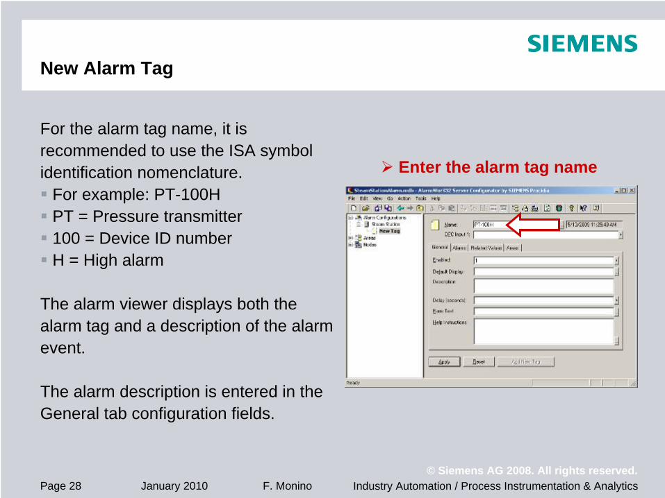
For the alarm tag name, it is recommended to use the ISA symbol identification nomenclature.
For example: PT-100HPT = Pressure transmitter100 = Device ID numberH = High alarm
The alarm viewer displays both the alarm tag and a description of the alarm event.
The alarm description is entered in the General tab configuration fields.
Enter the alarm tag name

Industry Automation / Process Instrumentation & Analytics© Siemens AG 2008. All rights reserved.
January 2010 F. MoninoPage 29
New Alarm Tag
Assign an OPC tagClick button next to OPC Input 1 text boxSelect OPC Tags

Industry Automation / Process Instrumentation & Analytics© Siemens AG 2008. All rights reserved.
January 2010 F. MoninoPage 30
OPC Tag Browser
This opens the OPC Tag Browser.
Alarm tags are associated with at least one OPC tag.
The Alarm Server monitors the OPC tag in order to determine an alarm event.
Select an OPC tagExpand My ComputerExpand Data AccessSelect OPC ServerSelect OPC tagClick OK button

Industry Automation / Process Instrumentation & Analytics© Siemens AG 2008. All rights reserved.
January 2010 F. MoninoPage 31
New Alarm Tag
Save new alarm tag
Click Apply button

Industry Automation / Process Instrumentation & Analytics© Siemens AG 2008. All rights reserved.
January 2010 F. MoninoPage 32
Alarm Tag Description
Alarm tags are listed under the Alarm Server configuration icon.
In the General tab panel, the alarm tag description text is entered.
Configure Alarm Tag descriptionSelect General tabEnter 1 into Enabled fieldEnter Base TextEnter Help Instructions

Industry Automation / Process Instrumentation & Analytics© Siemens AG 2008. All rights reserved.
January 2010 F. MoninoPage 33
General Tab
EnabledThis parameter tells the Alarm Server to monitor the tag.Always set value to 1.Alternate OPC tag method enables and disables the tag during run-time.
Default DisplayAdvance option to open a display file
DescriptionOptional field for user-specific commentsText is not available to Alarm Viewer.

Industry Automation / Process Instrumentation & Analytics© Siemens AG 2008. All rights reserved.
January 2010 F. MoninoPage 34
General Tab
Base TextThe Base Text is the description of the monitored process variable.
For example: Boiler 1 Drum LevelThe active alarm state is described in the Alarm Message field.
For example: HighIn the Alarm Viewer, the active alarm description consists of the “Base Text + the Alarm Message.”
For example: Boiler 1 Drum Level High
Help InstructionsThis is an optional feature available in the Alarm Viewer.It provides the operator with additional information as to the possible cause of the alarm event and appropriate action to take.

Industry Automation / Process Instrumentation & Analytics© Siemens AG 2008. All rights reserved.
January 2010 F. MoninoPage 35
Alarm Type
In the Alarms tab panel, the alarm type is specified.
Digital alarm type is recommended.
Configure the alarm typeSelect Alarms tabSelect Digital panel button

Industry Automation / Process Instrumentation & Analytics© Siemens AG 2008. All rights reserved.
January 2010 F. MoninoPage 36
Alarm Type
The Alarm Server polls both analog and discrete process variables.
The Alarm Server supports four types of alarms.Limit
An analog variable is greater than or less than a fixed limit value.
DeviationThe difference between two analog variables is greater than a deadband.
Rate of ChangeAn analog variable changes value faster than a rate of change limit (units/second).
DigitalA discrete variable is either true or false.

Industry Automation / Process Instrumentation & Analytics© Siemens AG 2008. All rights reserved.
January 2010 F. MoninoPage 37
Alarm Type
The Digital alarm type is recommended.
For analog process variables, let the controller determine when the variable is in an alarm state.
The ALARM and ODA function blocks support limit and deviation alarms.The active alarm status is read as a Modbus Coil.
Configure the Alarm Server to poll discrete alarm tags.A value of 1 indicates an active alarm.A value of 0 indicates that the process is normal.
In run-time, it is easier for operators to change alarm limits via the controller faceplate.

Industry Automation / Process Instrumentation & Analytics© Siemens AG 2008. All rights reserved.
January 2010 F. MoninoPage 38
Alarms Tab – Digital Panel
Configure the Digital alarmEnter 1 in Alarm State ValueEnter Message TextEnter SeverityEnter Req Ack value (0 or 1)Enter Return to Normal text

Industry Automation / Process Instrumentation & Analytics© Siemens AG 2008. All rights reserved.
January 2010 F. MoninoPage 39
Alarms Tab – Digital Panel
Alarm State ValueIt specifies the value of a discrete variable when in alarm.In the 353 series controllers, 1 indicates an active alarm.When the value of the discrete variable matches the value in the Alarm State Value field, the Alarm Server posts the alarm tag as active.
Message TextMessage Text describes the state of the process variable when in alarm.It is the modifier to the Base Text.In the Alarm Viewer, the alarm description is the “Base Text + Message Text.”

Industry Automation / Process Instrumentation & Analytics© Siemens AG 2008. All rights reserved.
January 2010 F. MoninoPage 40
Alarms Tab – Digital Panel
SeveritySeverity is a method to classify alarms.
Critical alarmsWarning alarmsProcess events
Severity value can be 0 through 999.
In the Alarm Viewer, an alarm message can be displayed using different background and text colors depending on the severity value.
This provides the operator with a visual indication between alarms and process events.

Industry Automation / Process Instrumentation & Analytics© Siemens AG 2008. All rights reserved.
January 2010 F. MoninoPage 41
Alarms Tab – Digital Panel
Requires Acknowledgement
Req Ack = 1 (Yes)When an event occurs, a message is posted in the Alarm Viewer and the message status is set to Alarm (Active event and Not Ack’d).
When the message is acknowledged, the message status is changed to Acknowledged (Active and Ack’d).
When an Acknowledged event clears, the message is removed from the Alarm Viewer.
If an active event clears prior to being acknowledged, then the message status is changed to Unacknowledged (Not Active and Not Ack’d).
The operator must acknowledge an Unacknowledged message in order to remove it from the Alarm Viewer.

Industry Automation / Process Instrumentation & Analytics© Siemens AG 2008. All rights reserved.
January 2010 F. MoninoPage 42
Alarms Tab – Digital Panel
Requires Acknowledgement (continued)
Req Ack = 0 (No)
When an event occurs, a message is posted in the Alarm Viewer and the message status is set to Acknowledged (Active and Ack’d).
When the event clears, the message is removed from the Alarm Viewer.

Industry Automation / Process Instrumentation & Analytics© Siemens AG 2008. All rights reserved.
January 2010 F. MoninoPage 43
Alarms Tab – Digital Panel
Return To Normal
Applicable only when Req Ack = 1.
When an active event clears and becomes Unacknowledged, the return to normal message is displayed in the Description field.
“Base Text + Return to Normal text”

Industry Automation / Process Instrumentation & Analytics© Siemens AG 2008. All rights reserved.
January 2010 F. MoninoPage 44
Related Values Tab
This method allows for capturing of additional information when an alarm occurs.
For example in metal heat treating, the furnace temperature follows a specific profile over time. The alarm tag monitors temperature deviation. If an alarm occurs, it would be useful to know the actual temperature, setpoint temperature, and sequence time when the deviation occurred.
Up to 10 related values can be captured.

Industry Automation / Process Instrumentation & Analytics© Siemens AG 2008. All rights reserved.
January 2010 F. MoninoPage 45
Areas Tab
Areas are logical groupings of alarm tags.
Specific area or operating unit
Areas must first be created before a tag can be assigned to an area.
The Alarm Viewer can filter alarm tags by area and only post alarm messages specified in the Subscription Areas.

Industry Automation / Process Instrumentation & Analytics© Siemens AG 2008. All rights reserved.
January 2010 F. MoninoPage 46
Alarm Tag Configuration
Save configuration changes
Click Apply button

Industry Automation / Process Instrumentation & Analytics© Siemens AG 2008. All rights reserved.
January 2010 F. MoninoPage 47
Areas Configuration
Areas is optional.In large systems, it may be desirable to have separate Alarm Viewers for different equipment.Use areas to filter alarms tags.
Alarm tags are assigned to areas.First create areas, then assign alarm tags to the area.Optionally, tags can be assigned to an area if the area already exists.
An alarm tag can be a member of multiple areas.

Industry Automation / Process Instrumentation & Analytics© Siemens AG 2008. All rights reserved.
January 2010 F. MoninoPage 48
Areas Configuration
Add a new Area
Right mouse click Areas Select New/ Area

Industry Automation / Process Instrumentation & Analytics© Siemens AG 2008. All rights reserved.
January 2010 F. MoninoPage 49
Areas Configuration
Enter Area Name
Click Apply button

Industry Automation / Process Instrumentation & Analytics© Siemens AG 2008. All rights reserved.
January 2010 F. MoninoPage 50
Areas Configuration
Assign tags to Area
Right mouse click new AreaSelect New/ Insert New Link to Tags

Industry Automation / Process Instrumentation & Analytics© Siemens AG 2008. All rights reserved.
January 2010 F. MoninoPage 51
Areas Configuration
This opens the Alarm Tag Selector.
An extra alarm tag was added to demonstrate that the dialog box will list all tags in the configuration.
It also demonstrates that multiple tags can be added to an area.
Select alarm tag(s)Click OK button

Industry Automation / Process Instrumentation & Analytics© Siemens AG 2008. All rights reserved.
January 2010 F. MoninoPage 52
Areas Configuration
All alarm tags are listed under the Alarm Server Configuration icon.
All tags assigned to an area are listed under the Area folder.

Industry Automation / Process Instrumentation & Analytics© Siemens AG 2008. All rights reserved.
January 2010 F. MoninoPage 53
Areas Configuration
Areas tab panel shows that PT-100-H tag has been assigned to North Building area.
Click on PT-100-H tagSelect Areas tab

Industry Automation / Process Instrumentation & Analytics© Siemens AG 2008. All rights reserved.
January 2010 F. MoninoPage 54
Nodes Configuration
Nodes configuration is required.The node is the PC name with the Alarm Management Configuration.In the Alarm Viewer configuration, the node must be specified.
Two fields are configured.Node Name
Identifies PC with Alarm Management Configuration
Configuration NameSpecifies the active Alarm Server configuration

Industry Automation / Process Instrumentation & Analytics© Siemens AG 2008. All rights reserved.
January 2010 F. MoninoPage 55
Nodes Configuration
Add Node
Right mouse click NodesSelect New/ Node

Industry Automation / Process Instrumentation & Analytics© Siemens AG 2008. All rights reserved.
January 2010 F. MoninoPage 56
Nodes Configuration
Click Configuration Name drop-down list box Select Alarm Server Configuration
Click Apply button
Enter PC Name

Industry Automation / Process Instrumentation & Analytics© Siemens AG 2008. All rights reserved.
January 2010 F. MoninoPage 57
Nodes Configuration
Configured node

Protection notice / Copyright notice
AlarmWorX32 Alarm Server
© Siemens AG 2008. All rights reserved.

Industry Automation / Process Instrumentation & Analytics© Siemens AG 2008. All rights reserved.
January 2010 F. MoninoPage 59
AlarmWorX32 Server
AlarmWorX32 Server does not have a graphical user interface (GUI).
The Alarm Server can be started and stopped manually usingAlarmWorX32 Server Configurator, orGenTray utility
GenTray utility manages Procidia iWare servers.
The Alarm Server can also be started automatically from GraphWorX32.If the Alarm Server is not running when an Alarm Viewer is started, then GraphWorX32 starts the Server; however, it also closes the Server once the Viewer is closed.This results in inconsistent alarm status information.

Industry Automation / Process Instrumentation & Analytics© Siemens AG 2008. All rights reserved.
January 2010 F. MoninoPage 60
AlarmWorX32 Server
In order to preserve alarm status information, the Alarm server should be started when the Procidia application is started and allowed to run continuously in the background.
Use the GenTray utility to start the Alarm Server when the application is started.The GenTray utility can be configured to automatically start the Alarm Server at startup.GenTray is also used to manually start and stop the Server when required.

Industry Automation / Process Instrumentation & Analytics© Siemens AG 2008. All rights reserved.
January 2010 F. MoninoPage 61
AlarmWorX32 Server Configurator
The Alarm Server can be started manually from the Configurator.
Action menu option, orTraffic Light tool bar button
Start Alarm ServerSelect menu bar Action/ Start Alarm Serveror Click on Traffic Light tool bar button
Industry Automation / Process Instrumentation & Analytics© Siemens AG 2008. All rights reserved.
January 2010 F. MoninoPage 62
AlarmWorX32 Server Configurator
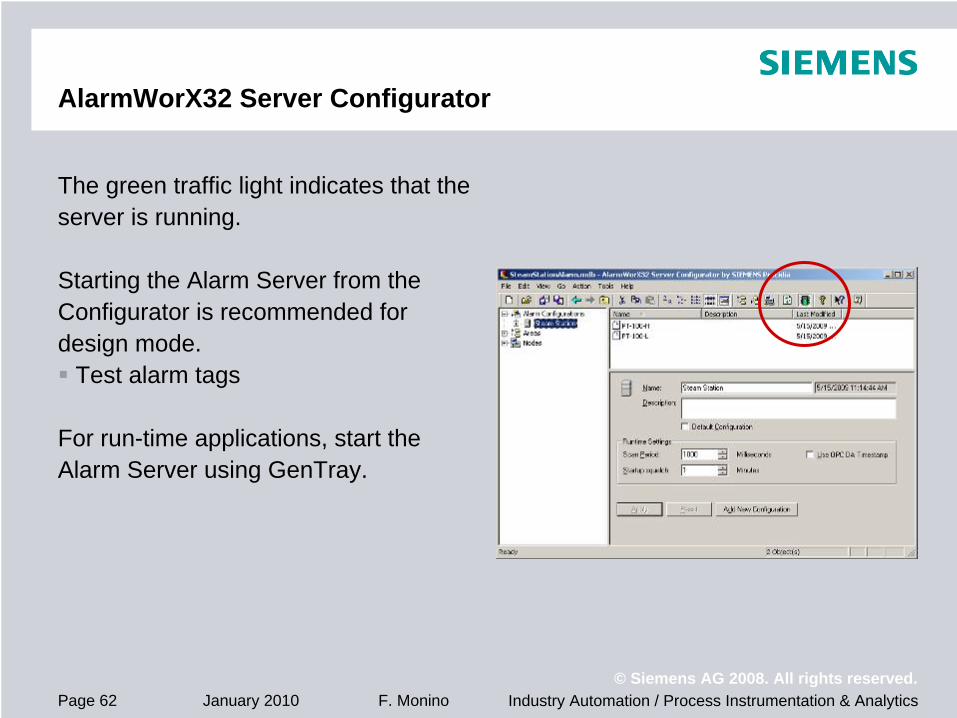
The green traffic light indicates that the server is running.
Starting the Alarm Server from the Configurator is recommended for design mode.
Test alarm tags
For run-time applications, start the Alarm Server using GenTray.

Industry Automation / Process Instrumentation & Analytics© Siemens AG 2008. All rights reserved.
January 2010 F. MoninoPage 63
GenTray
Open GenTray utilityClick task bar Start buttonSelect Programs/ SIEMENS Procidia/ iWare PC/ Tools/ GenTray

Industry Automation / Process Instrumentation & Analytics© Siemens AG 2008. All rights reserved.
January 2010 F. MoninoPage 64
GenTray
When GenTray is opened, a pink triangle icon appears in the task bar notification area.
GenTray manages the Procidia iWare servers.It starts and stops servers manually or automatically.
GenTray is the method to ensure that the Alarm Server is started when the Procidia application is started.
An operator may not remember to launch the alarm server.

Industry Automation / Process Instrumentation & Analytics© Siemens AG 2008. All rights reserved.
January 2010 F. MoninoPage 65
GenTray
When GenTray is started, it starts all servers configured to Auto start.
Configure GenTray to Auto Start the AlarmWorX32 ServerClick on GenTray iconSelect AlarmWorX32Select AlarmWorX32 ServerClick Auto Start

Industry Automation / Process Instrumentation & Analytics© Siemens AG 2008. All rights reserved.
January 2010 F. MoninoPage 66
GenTray
Check mark indicates that the Auto Start feature is enabled.
The Alarm Server can also be started and stopped manually.
If Start is enable and Stop is grayed- out, then the server is stopped.
Click Start to start server.
If Stop is enabled and Start is grayed- out, then the server is running.
Click Stop to stop server.

Industry Automation / Process Instrumentation & Analytics© Siemens AG 2008. All rights reserved.
January 2010 F. MoninoPage 67
GenTray
Refer to GenTray tutorial for more configuration details.
It illustrates method to automatically start GenTray when the operator logs on to the engineering station.
It illustrates method to control the start sequence of the Alarm Server.Order in which servers are startedTime delay before starting a server

Protection notice / Copyright notice© Siemens AG 2008. All rights reserved.
Technical SupportTel: 1-800-333-7421Hours: 8:00 am – 4:45 pm M-F (except holidays)
Internet Support Requesthttp://www.siemens.com/automation/support-request
Public Internet Sitehttp://www.usa.siemens.com/PI
Technical Support