ProAct™ V Electric Powered Actuator and Driver · ProAct™ V Electric Powered Actuator and...
40
Installation and Operation Manual ProAct™ V Electric Powered Actuator and Driver Manual 04193 (Revision A)
-
Upload
vuongxuyen -
Category
Documents
-
view
235 -
download
0
Transcript of ProAct™ V Electric Powered Actuator and Driver · ProAct™ V Electric Powered Actuator and...

Installation and Operation Manual
ProAct™ V Electric Powered Actuator and Driver
Manual 04193 (Revision A)

DEFINITIONS
This is the safety alert symbol. It is used to alert you to potential personal injury hazards. Obey all safety messages that follow this symbol to avoid possible injury or death.
• DANGER—Indicates a hazardous situation which, if not avoided, will result in death or serious injury.
• WARNING—Indicates a hazardous situation which, if not avoided, could result in death or serious injury.
• CAUTION—Indicates a hazardous situation which, if not avoided, could result in minor or moderate injury.
• NOTICE—Indicates a hazard that could result in property damage only (including damage to the control).
• IMPORTANT—Designates an operating tip or maintenance suggestion.
The engine, turbine, or other type of prime mover should be equipped with an overspeed shutdown device to protect against runaway or damage to the prime mover with possible personal injury, loss of life, or property damage.
The overspeed shutdown device must be totally independent of the prime mover control system. An overtemperature or overpressure shutdown device may also be needed for safety, as appropriate.
Read this entire manual and all other publications pertaining to the work to be performed before installing, operating, or servicing this equipment. Practice all plant and safety instructions and precautions. Failure to follow instructions can cause personal injury and/or property damage.
This publication may have been revised or updated since this copy was produced. To verify that you have the latest revision, be sure to check the Woodward website:
www.woodward.com/pubs/current.pdf The revision level is shown at the bottom of the front cover after the publication number. The latest version of most publications is available at:
www.woodward.com/publications If your publication is not there, please contact your customer service representative to get the latest copy.
Any unauthorized modifications to or use of this equipment outside its specified mechanical, electrical, or other operating limits may cause personal injury and/or property damage, including damage to the equipment. Any such unauthorized modifications: (i) constitute "misuse" and/or "negligence" within the meaning of the product warranty thereby excluding warranty coverage for any resulting damage, and (ii) invalidate product certifications or listings.
To prevent damage to a control system that uses an alternator or battery-charging device, make sure the charging device is turned off before disconnecting the battery from the system.
To prevent damage to electronic components caused by improper handling, read and observe the precautions in Woodward manual 82715, Guide for Handling and Protection of Electronic Controls, Printed Circuit Boards, and Modules.
Revisions—Text changes are indicated by a black line alongside the text. Woodward Governor Company reserves the right to update any portion of this publication at any time. Information provided by Woodward Governor Company is believed to be correct and reliable. However, no responsibility is assumed by Woodward Governor Company unless otherwise expressly undertaken.
© Woodward 1999 All Rights Reserved
Manual 04193 ProAct V Actuator/Driver
Woodward i
Contents
ELECTROSTATIC DISCHARGE AWARENESS .................................................. III CHAPTER 1. GENERAL INFORMATION ........................................................... 1 CHAPTER 2. INSTALLATION.......................................................................... 9 Driver Installation .................................................................................................... 9 Actuator Installation ................................................................................................ 9 Mounting ............................................................................................................... 11 Electrical Connections .......................................................................................... 11 Power Supply ....................................................................................................... 12 Driver Adjustments ............................................................................................... 13
CHAPTER 3. DESCRIPTION OF OPERATION ................................................. 16 Electronic Circuits ................................................................................................. 16 Actuator Position Signal ....................................................................................... 17 Actuator ................................................................................................................ 17
CHAPTER 4. TROUBLESHOOTING ............................................................... 18 Introduction ........................................................................................................... 18 Linkage and Actuator Stroke ................................................................................ 18
CHAPTER 5. TECHNICAL SPECIFICATIONS .................................................. 20 Power Supply ....................................................................................................... 20 Actuator Position Feedback.................................................................................. 20 System Wiring ...................................................................................................... 20 Input Configurations ............................................................................................. 21 Low Command Shutdown .................................................................................... 22 System Performance ............................................................................................ 22
CHAPTER 6. PROACT™ V DRIVER DETAILED SPECIFICATIONS ................... 24 Driver Regulatory Compliance ............................................................................. 24 Environmental Specifications ............................................................................... 24 Electrical Specifications ........................................................................................ 25
CHAPTER 7. PROACT™ V ACTUATOR DETAILED SPECIFICATIONS ............. 26 Actuator Regulatory Compliance .......................................................................... 26 Environmental Specifications ............................................................................... 26
CHAPTER 8. SERVICE OPTIONS ................................................................. 27 Product Service Options ....................................................................................... 27 Woodward Factory Servicing Options .................................................................. 28 Returning Equipment for Repair ........................................................................... 29 Replacement Parts ............................................................................................... 29 Engineering Services ............................................................................................ 30 How to Contact Woodward ................................................................................... 30 Technical Assistance ............................................................................................ 31
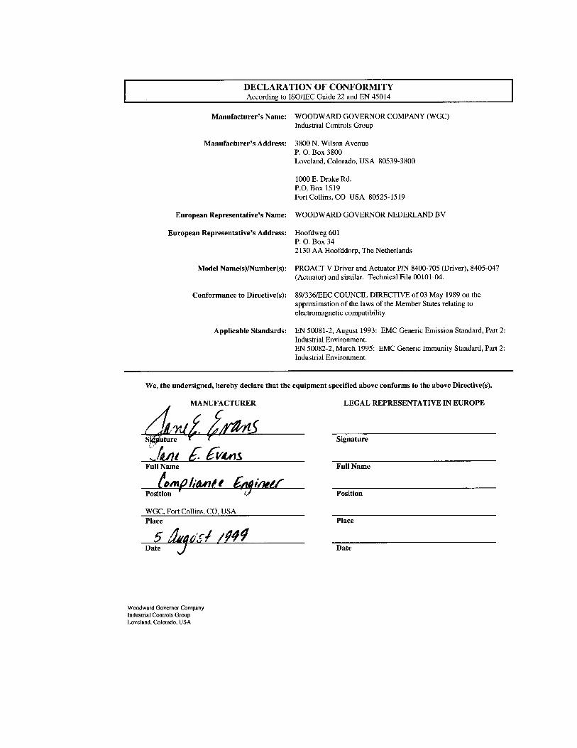
DECLARATIONS ......................................................................................... 32

ProAct V Actuator/Driver Manual 04193
ii Woodward
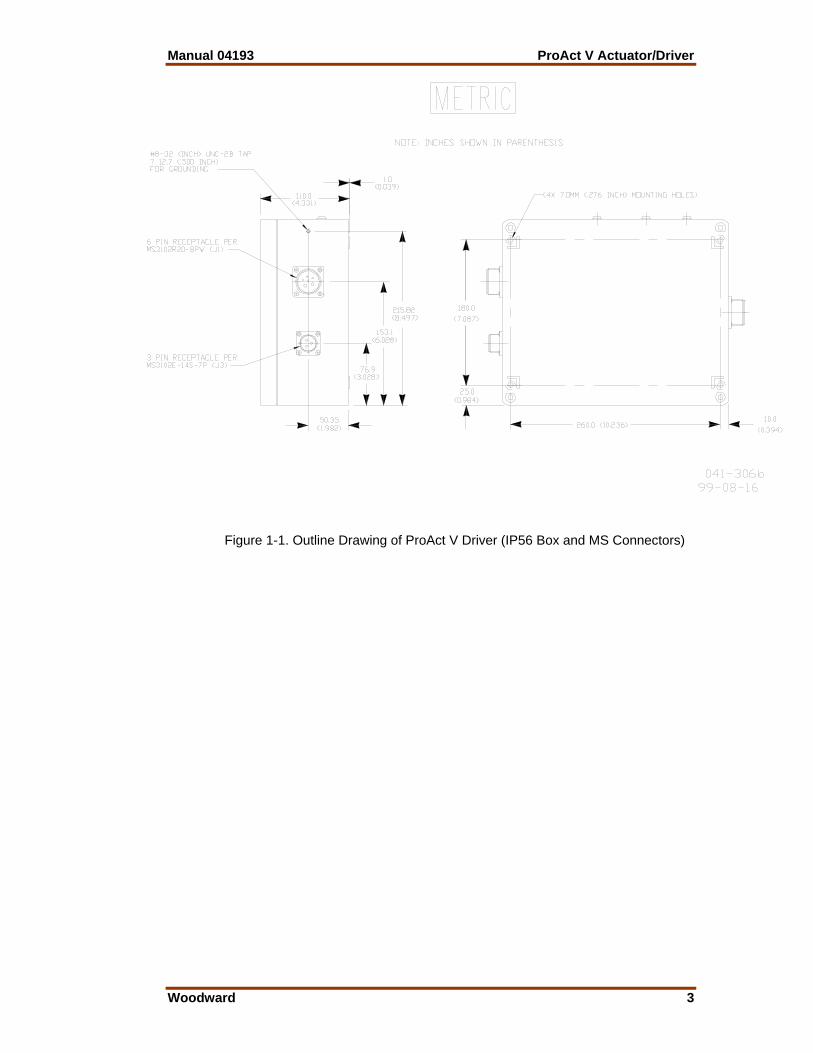
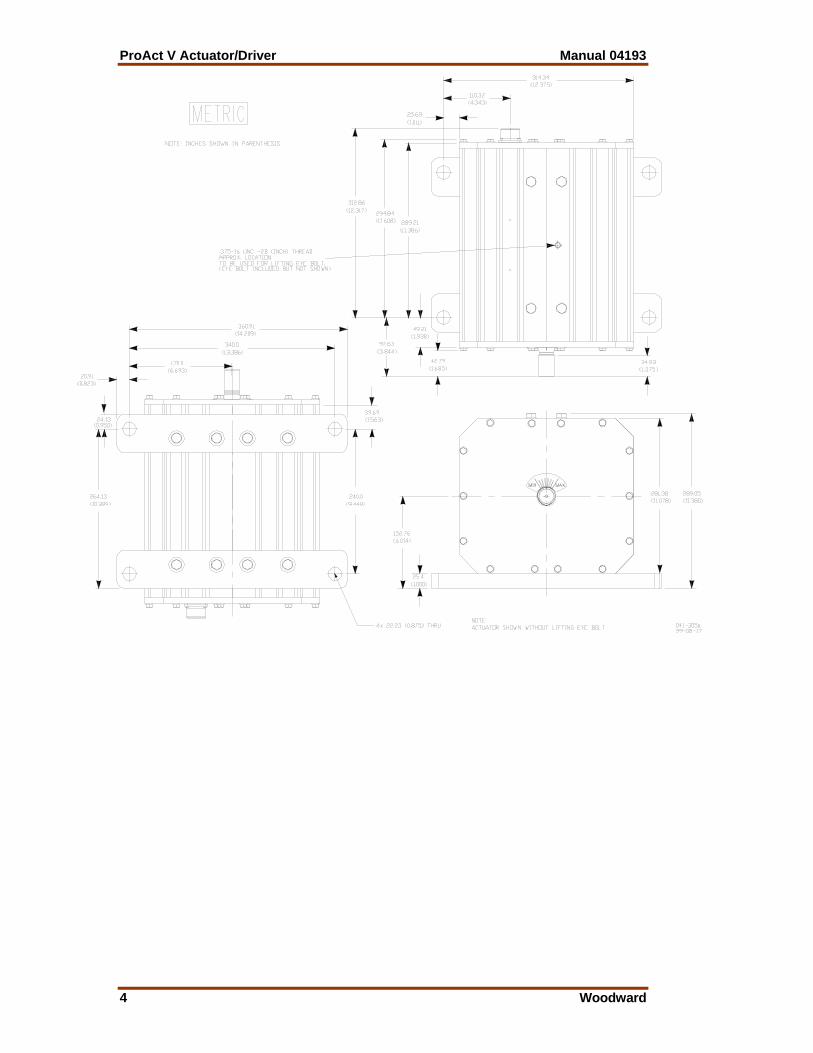
Illustrations and Tables Figure 1-1. Outline Drawing of ProAct V Driver (IP56 Box and MS Connectors) .. 3 Figure 1-2. Outline Drawing of ProAct V Actuator (CW actuator shown) ............... 5 Figure 1-3. Plant Wiring Diagram ........................................................................... 7 Figure 1-4. ProAct Driver Connector Positions ...................................................... 8 Figure 2-1. Typical Engine Travel Stops .............................................................. 10 Figure 2-2. Preparing Shielded Wiring ................................................................. 12 Figure 2-3. Wiring to Power Supply ...................................................................... 13 Figure 2-4. ProAct V Driver Adjustment Locations ............................................... 14 Figure 3-1. ProAct V Functional Block Diagram ................................................... 16 Table 1-1. Available Position Command Input Configurations ............................... 1 Table 5-1. Wiring Harness Configurations ........................................................... 20 Table 5-2. Low Command Shutdown ................................................................... 22

Manual 04193 ProAct V Actuator/Driver
Woodward iii
Electrostatic Discharge Awareness All electronic equipment is static-sensitive, some components more than others. To protect these components from static damage, you must take special precautions to minimize or eliminate electrostatic discharges. Follow these precautions when working with or near the control. 1. Before doing maintenance on the electronic control, discharge the static
electricity on your body to ground by touching and holding a grounded metal object (pipes, cabinets, equipment, etc.).
2. Avoid the build-up of static electricity on your body by not wearing clothing
made of synthetic materials. Wear cotton or cotton-blend materials as much as possible because these do not store static electric charges as much as synthetics.
3. Keep plastic, vinyl, and Styrofoam materials (such as plastic or Styrofoam
cups, cup holders, cigarette packages, cellophane wrappers, vinyl books or folders, plastic bottles, and plastic ash trays) away from the control, the modules, and the work area as much as possible.
4. Do not remove the printed circuit board (PCB) from the control cabinet
unless absolutely necessary. If you must remove the PCB from the control cabinet, follow these precautions:
• Do not touch any part of the PCB except the edges. • Do not touch the electrical conductors, the connectors, or the
components with conductive devices or with your hands. • When replacing a PCB, keep the new PCB in the plastic antistatic
protective bag it comes in until you are ready to install it. Immediately after removing the old PCB from the control cabinet, place it in the antistatic protective bag.
To prevent damage to electronic components caused by improper handling, read and observe the precautions in Woodward manual 82715, Guide for Handling and Protection of Electronic Controls, Printed Circuit Boards, and Modules.

ProAct V Actuator/Driver Manual 04193
iv Woodward

Manual 04193 ProAct V Actuator/Driver
Woodward 1
Chapter 1. General Information
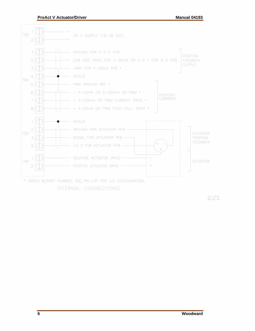
The ProAct™ V driver converts either a 0–200 mA, 4–20 mA, or a PWM control signal from a Woodward electronic control into a specific actuator position. The driver provides a feedback of 0.5–4.5 V or a 4–20 mA signal corresponding to actuator position. The ProAct V driver is supplied with a sealed aluminum box with MS connectors for wiring. The box is IP56 capable and is designed for skid-mounted applications. The ProAct V drivers require a separate electrical supply of 18–32 Vdc. The supply must be capable of providing a sustained 10 A signal and a peak 20 A signal for up to one second for the driver. The ProAct actuator provides up to 78.6 J (58.0 ft-lbs) of transient work and 39.3 J (29.0 ft-lbs) of steady state work over 70° of travel to move the fuel-setting lever on the engine. The actuator has position feedback and is available in clockwise-to- increase-fuel or counterclockwise-to-increase-fuel versions. Engine stability and response are set by the controlling device, not by the actuator and driver. Follow the instructions for the controlling device while setting up the engine control system. The following configurations are available for the position command input.
Input Signal
Position Feedback Signal
Nominal Input Range
Actuator Output for Input Range
Package Configuration
7–32 V 100–3000 Hz PWM push-pull source
0-5 V output 10% to 90% duty cycle
0% to 100% actuator position
IP56 box with MS connectors
7–32 V 100–3000 Hz PWM current/voltage source
0-5 V output 10% to 90% duty cycle
0% to 100% actuator position
IP56 box with MS connectors
0 to 200 mA 4-20 mA output 20 to 160 mA 0% to 100% actuator position
IP56 box with MS connectors
0 to 200 mA 0-5 V output 20 to 160 mA 0% to 100% actuator position
IP56 box with MS connectors
4 to 20 mA 4-20 mA output 4 to 20 mA 0% to 100% actuator position
IP56 box with MS connectors
4 to 20 mA 0-5 V output 4 to 20 mA 0% to 100% actuator position
IP56 box with MS connectors
Table 1-1. Available Position Command Input Configurations
ProAct V Actuator/Driver Manual 04193
2 Woodward
Manual 04193 ProAct V Actuator/Driver
Woodward 3
Figure 1-1. Outline Drawing of ProAct V Driver (IP56 Box and MS Connectors)
ProAct V Actuator/Driver Manual 04193
4 Woodward
Manual 04193 ProAct V Actuator/Driver
Woodward 5
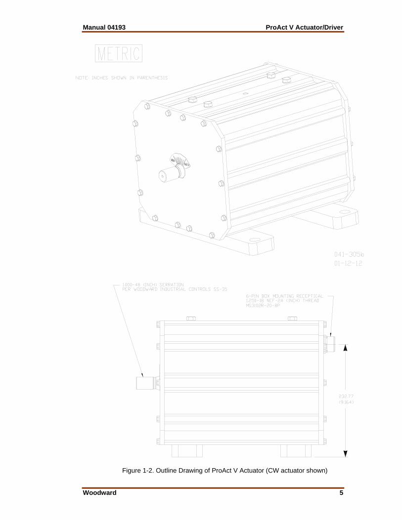
Figure 1-2. Outline Drawing of ProAct V Actuator (CW actuator shown)
ProAct V Actuator/Driver Manual 04193
6 Woodward
Manual 04193 ProAct V Actuator/Driver
Woodward 7
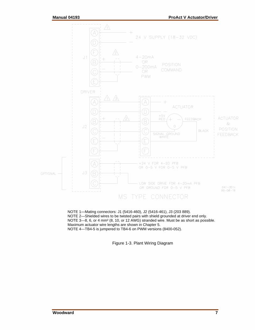
NOTE 1—Mating connectors: J1 (5416-460), J2 (5416-461), J3 (203 889). NOTE 2—Shielded wires to be twisted pairs with shield grounded at driver end only. NOTE 3—8, 6, or 4 mm² (8, 10, or 12 AWG) stranded wire. Must be as short as possible. Maximum actuator wire lengths are shown in Chapter 5. NOTE 4—TB4-5 is jumpered to TB4-6 on PWM versions (8400-052).
Figure 1-3. Plant Wiring Diagram
ProAct V Actuator/Driver Manual 04193
8 Woodward
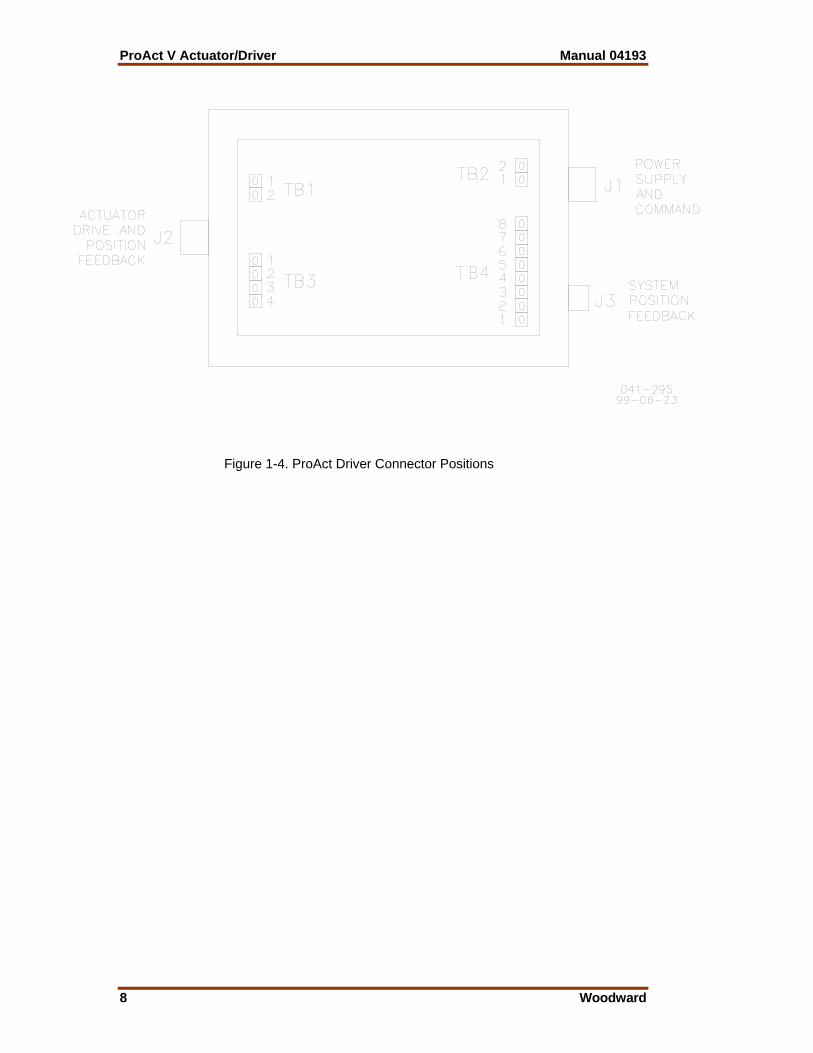
Figure 1-4. ProAct Driver Connector Positions

Manual 04193 ProAct V Actuator/Driver
Woodward 9
Chapter 2. Installation
Driver Installation Unpacking Be careful when unpacking the electronic driver. Check the driver for signs of damage, such as bent or dented panels, scratches, and loose or broken parts. Notify the shipper and Woodward if damage is found. The driver weighs 3.6 kg (8.0 lbs). Mounting The driver box is designed to operate within a temperature range of –40 to +70 °C (–40 to +158 °F). For environmental specifications, see Chapter 6. If the application has a higher vibration level than 0.04 G²/Hz, vibration isolators must be used to keep the levels below this. Mount the driver in a location with space for adjustment and wiring access. Do not expose the driver to sources of radiant heat such as exhaust manifolds or turbochargers. Wire length requirements (described in Chapter 5) between the driver, actuator, and power source must be met. The driver will generate some heat, so surfaces must be open to normal air movement. No special ventilation is required. Ideally, the driver should be mounted flush to the metal side of a control cabinet, protected from the weather and high humidity, and close to the engine being controlled. Do not install the driver directly on the engine. The location should provide protection from high-voltage or high-current devices, or devices which produce electromagnetic interference. After initial adjustments are completed, access to the driver will not be required for normal engine operation.
Actuator Installation Unpacking The ProAct™ V actuator weighs 77 kg (170 lbs). A lifting eyebolt is provided for easier handling (see Figure 1-2). Thermal Considerations For environmental specifications, see Chapter 7.

ProAct V Actuator/Driver Manual 04193
10 Woodward
The actuators are designed for installation on the engine. The actuators will generate heat, especially when stalled or during other conditions requiring maximum torque output. Operating temperature for the ProAct V actuator is –40 to +100 °C (–40 to +212 °F). The installer must consider the heat conductivity of the installation bracket, and the operating temperature of the ultimate heat sink to which the bracket will be attached, to ensure that neither the mounting point of the actuator nor the surrounding air exceed 100 °C. Generally the heat transfer abilities of aluminum and low-carbon steel are better than those of high-carbon steel or stainless steel. If operating temperature is a concern, contact Woodward for more information. Fuel Position Stops Installations must provide for fuel system minimum and maximum position stops. The fuel linkage stops must be within the travel allowed by the actuator's stops. The linkage should be designed to use as much actuator travel as possible, without contacting the actuator stops (see Figure 2-1).
Figure 2-1. Typical Engine Travel Stops
The actuator's maximum slew rate can place stress on fuel system stops and on the linkage between the actuator and the fuel system. The maximum energy absorption can be determined by calculating the system’s kinetic energy. For this calculation, maximum actuator speed is 700 degrees per second in both the increase and decrease fuel directions, and the actuator's Mass Moment of Inertia (MMOI) is 0.0072 N-m-sec². The load inertia must be added to this, and then KE=½JW².
Use good, energy-absorbing rod-end connectors with as little free play as possible. Select rod ends which will not become loose and which will wear well during the nearly constant movement associated with precise speed control. Low- friction, long-wearing rod ends are available from Woodward. The link connecting the actuator lever to the fuel-control lever must be designed to prevent flexing when the engine is running. This can be accomplished by a short lever or stiff material.

Manual 04193 ProAct V Actuator/Driver
Woodward 11
Use as much of the 70-degree rotation as possible. To increase the amount of rotation, move the rod end closer to the actuator shaft or farther away from the shaft controlling fuel flow. To decrease the amount of rotation used, move the rod end farther from the actuator shaft or closer to the shaft controlling fuel flow.
Mounting The actuator may be installed directly on the engine or on a bracket with four M20 screws. Ensure a minimum of 30 mm thread engagement. The actuator may be mounted in any attitude. The actuator is weatherproof and resistant to the corrosive effects of water and salt water. Avoid pressure washing near the shaft seals. The ProAct V actuator weighs 77 kg (170 lbs). Any bracket and attaching hardware must be designed to hold this weight and to withstand the vibration associated with engine mounting. The bracket must also be designed to provide a heat sink (heat transfer) from the actuator to the engine block. Always use the included lifting eye bolt to move the actuator.
Electrical Connections External wiring connections and shielding requirements for a typical control installation are shown in the plant wiring diagram (see Figure 1-3). The type and gauge of the wiring used should follow the wire length and type shown in the System Wiring section of Chapter 5, and must be in accordance with required electrical codes. Shielded Wiring All shielded cable must be twisted conductor pairs. Do not attempt to tin the braided shield. All signal lines should be shielded to prevent picking up stray signals from adjacent equipment. Connect the shields to the correct pins on the driver connector or wiring. Do not connect shields to the actuator ground. Wire exposed beyond the shield should be as short as possible, not exceeding 50 mm (2 inches). The other end of the shields must be left open and insulated from any other conductor. DO NOT run shielded signal wires along with other wires carrying large currents. See Woodward application note 50532, Interference Control in Electronic Governing Systems, for more information. Where shielded cable is required, cut the cable to the desired length and prepare the cable as instructed below (see Figure 2-2). Strip outer insulation from BOTH ENDS, exposing the braided or spiral wrapped shield. DO NOT CUT THE SHIELD. Using a sharp, pointed tool, carefully spread the strands of the shield. Pull the inner conductor(s) out of the shield. If the shield is the braided type, twist it to prevent fraying. Remove 6 mm (1/4 inch) of insulation from the inner conductors. The shield must be considered as a separate circuit when wiring the system. The shield must be carried through connectors without interruption.

ProAct V Actuator/Driver Manual 04193
12 Woodward
Figure 2-2. Preparing Shielded Wiring Installations with severe electromagnetic interference (EMI) may require additional shielding precautions. Contact Woodward for more information. Failure to provide shielding can produce future conditions which are difficult to diagnose. Proper shielding at the time of installation is required to assure satisfactory operation of the ProAct control system.
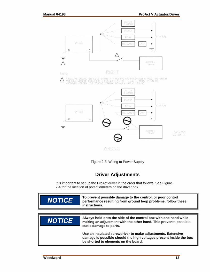
Power Supply Power supply output must be low impedance (for example, directly from batteries). Run an insulated wire directly from the positive (+) battery terminal and negative (–) battery terminal to the correct connection on the driver (see Figure 1-5). Run a second insulated wire directly from the negative (–) terminal of the battery to the driver. Neither of these connections needs to be shielded (see Figure 2-3 for correct installation). Run the power leads directly from the power source to the control. DO NOT POWER OTHER DEVICES WITH LEADS COMMON TO THE CONTROL. If the power source is a battery, be sure the system includes an alternator or other battery-charging device (see Figure 2-3).
Do not remove power from the driver for normal shutdown procedures. All actuator position commands should come from the control unit, through the driver, to the actuator. Engine overspeed is possible if power is removed from the driver while the engine is running.
Manual 04193 ProAct V Actuator/Driver
Woodward 13
Figure 2-3. Wiring to Power Supply
Driver Adjustments It is important to set up the ProAct driver in the order that follows. See Figure 2-4 for the location of potentiometers on the driver box.
To prevent possible damage to the control, or poor control performance resulting from ground loop problems, follow these instructions.
Always hold onto the side of the control box with one hand while making an adjustment with the other hand. This prevents possible static damage to parts. Use an insulated screwdriver to make adjustments. Extensive damage is possible should the high voltages present inside the box be shorted to elements on the board.
ProAct V Actuator/Driver Manual 04193
14 Woodward
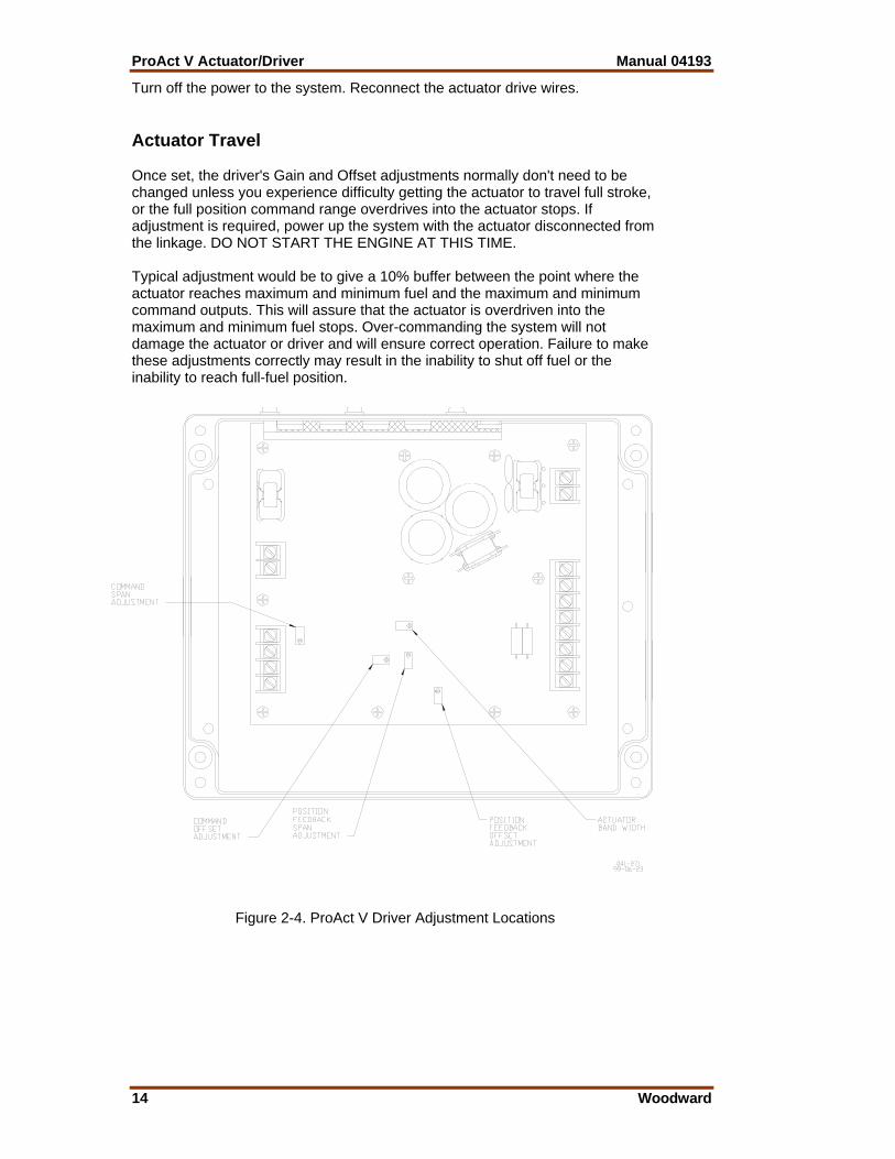
Turn off the power to the system. Reconnect the actuator drive wires. Actuator Travel Once set, the driver's Gain and Offset adjustments normally don't need to be changed unless you experience difficulty getting the actuator to travel full stroke, or the full position command range overdrives into the actuator stops. If adjustment is required, power up the system with the actuator disconnected from the linkage. DO NOT START THE ENGINE AT THIS TIME. Typical adjustment would be to give a 10% buffer between the point where the actuator reaches maximum and minimum fuel and the maximum and minimum command outputs. This will assure that the actuator is overdriven into the maximum and minimum fuel stops. Over-commanding the system will not damage the actuator or driver and will ensure correct operation. Failure to make these adjustments correctly may result in the inability to shut off fuel or the inability to reach full-fuel position.
Figure 2-4. ProAct V Driver Adjustment Locations

Manual 04193 ProAct V Actuator/Driver
Woodward 15
To calibrate the actuator travel, power up the system and set the position command input to minimum (usually 4 mA on a 4–20 mA unit, 20 mA on a 20–160 mA unit, or 10% duty cycle on a PWM unit). With the unit at minimum position input command, adjust the Command Offset Adjustment (see Figure 2-4) for minimum actuator position. Once this adjustment is made, change the position command input to maximum (usually 20 mA on a 4–20 mA unit, 160 mA on a 20–160 mA unit, or 90% duty cycle on a PWM unit). With the unit at maximum position input command, adjust the Command Span Adjustment (see Figure 2-4) for maximum actuator position. Since there is an interaction between the Command Offset Adjustment and Command Span Adjustment, these steps will have to be repeated until the desired command input vs actuator travel relationship is met. The actuator position feedback (internal to the actuator) is factory set and should not be adjusted. This procedure must be repeated whenever the actuator or driver is changed. The Gain and Offset pots are both located on the printed circuit board inside the driver box (see Figure 2-4). Position Feedback Output Adjustment Once set, the driver’s position feedback Gain and Offset adjustments normally do not need to be changed unless you experience feedback values outside the normal operating parameters of the driver. If adjustment is required, power up the system with the actuator disconnected from the linkage. DO NOT START THE ENGINE AT THIS TIME. To calibrate the position feedback adjustment, set the position command input to minimum and adjust the Position Feedback Offset Adjustment (see Figure 2-4) to minimum position feedback output (usually 4 mA on a 4–20 mA output unit or 0.5 V on a 0–5 V output unit). Once the adjustment is made, change the position command input to maximum and adjust the Position Feedback Span Adjustment (see Figure 2-4) to maximum position feedback output (usually 20 mA on a 4–20 mA output unit or 4.5 V on a 0–5 V output unit). Since there is an interaction between the Position Feedback Offset Adjustment and Position Feedback Span Adjustment, these steps will have to be repeated until the desired actuator travel vs position feedback output relationship is met. This procedure must be repeated whenever the actuator or driver is changed. The Gain and Offset pots are both located on the printed circuit board inside the driver box (see Figure 2-4). Actuator Bandwidth If the system response bandwidth is too large for proper system operation, the bandwidth can be reduced from the normal levels down to less than 2 Hz using the system bandwidth potentiometer (see Figure 2-4). Under normal conditions this potentiometer should be left in the factory (max bandwidth/fully clockwise) position.
The adjustment of the system position feedback output potentiometers does not affect the positioning of the actuator relative to the position input signal, or the response of the actuator to the position input signal.
ProAct V Actuator/Driver Manual 04193
16 Woodward
Chapter 3. Description of Operation
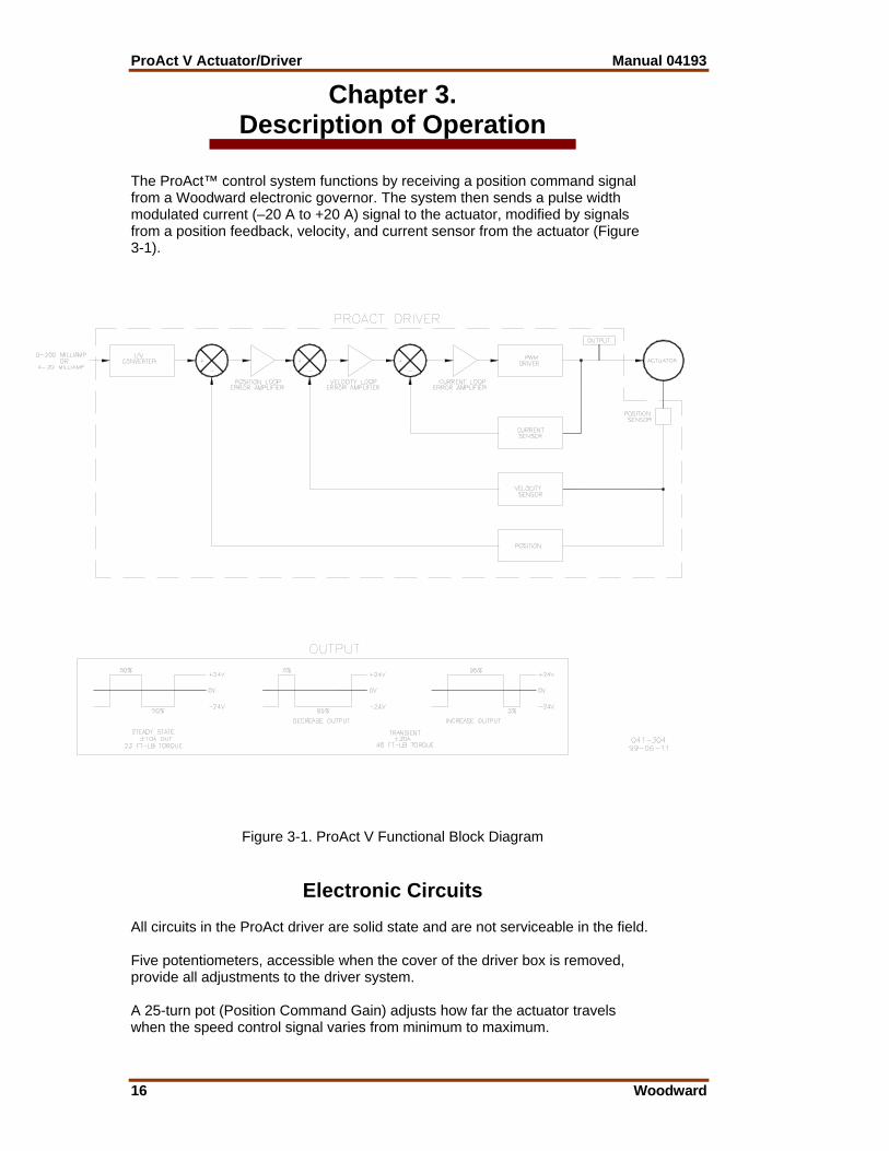
The ProAct™ control system functions by receiving a position command signal from a Woodward electronic governor. The system then sends a pulse width modulated current (–20 A to +20 A) signal to the actuator, modified by signals from a position feedback, velocity, and current sensor from the actuator (Figure 3-1).
Figure 3-1. ProAct V Functional Block Diagram
Electronic Circuits All circuits in the ProAct driver are solid state and are not serviceable in the field. Five potentiometers, accessible when the cover of the driver box is removed, provide all adjustments to the driver system. A 25-turn pot (Position Command Gain) adjusts how far the actuator travels when the speed control signal varies from minimum to maximum.
Manual 04193 ProAct V Actuator/Driver
Woodward 17
A 25-turn pot (Position Command Offset) adjusts the offset of the actuator travel when the speed control signal varies from minimum to maximum. A 25-turn pot (System Position Feedback Gain) adjusts the system position feedback gain as the actuator varies from minimum to maximum. A 25-turn pot (System Position Feedback Offset) adjusts the system position feedback offset as the actuator varies from minimum to maximum. A 25-turn pot (System Bandwidth Adjustment) adjusts the system bandwidth response to command signals.
Actuator Position Signal The feedback device is located on the closed shaft of the actuator. The device is a rotary transducer which changes voltage output proportional to the location of the shaft. The device is a non-contacting unit, thereby eliminating most wear problems.
Actuator The rotary design of the ProAct actuators gives 70 degrees of shaft rotation to position fuel controls. The actuators apply torque in both directions. Torque is proportional to the current supplied to the actuator by the driver. The actuator uses sealed bearings, eliminating the need for maintenance. The feedback mechanism attaches to the end of the rotor not being used to control the engine. The device is enclosed in the aluminum housing and therefore is sealed against the elements. Avoid pressure washing the actuator.

ProAct V Actuator/Driver Manual 04193
18 Woodward
Chapter 4. Troubleshooting
Introduction Improper engine operation is often the result of factors other than governor operation. This chapter gives tips about engine problems which can resemble governor problems. Make sure the engine is operating correctly before making any changes in the governor. Attempting to correct engine or load problems with untimely governor adjustment can make problems worse. If possible, isolate the governor from the engine to determine if the problem is with the governor and not with the engine or the load on the engine. Faults are usually caused by problems in the installation or the linkage between the actuator and the engine. Carefully review all the wiring connections, the power supply, and the linkage before making any adjustments to the actuator or driver. Always check the fuel-control linkage from stop to stop as if the actuator were moving it. The linkage must move freely without friction and without backlash. Some fuel controls will present problems at particular fuel or rack positions because of a hesitation or binding in the linkage. Fuel supply and injector conditions can also present problems which resemble governor problems. On spark-ignited engines, distributor, coil, points, and timing problems can all cause improper operations which may resemble faulty governor control.
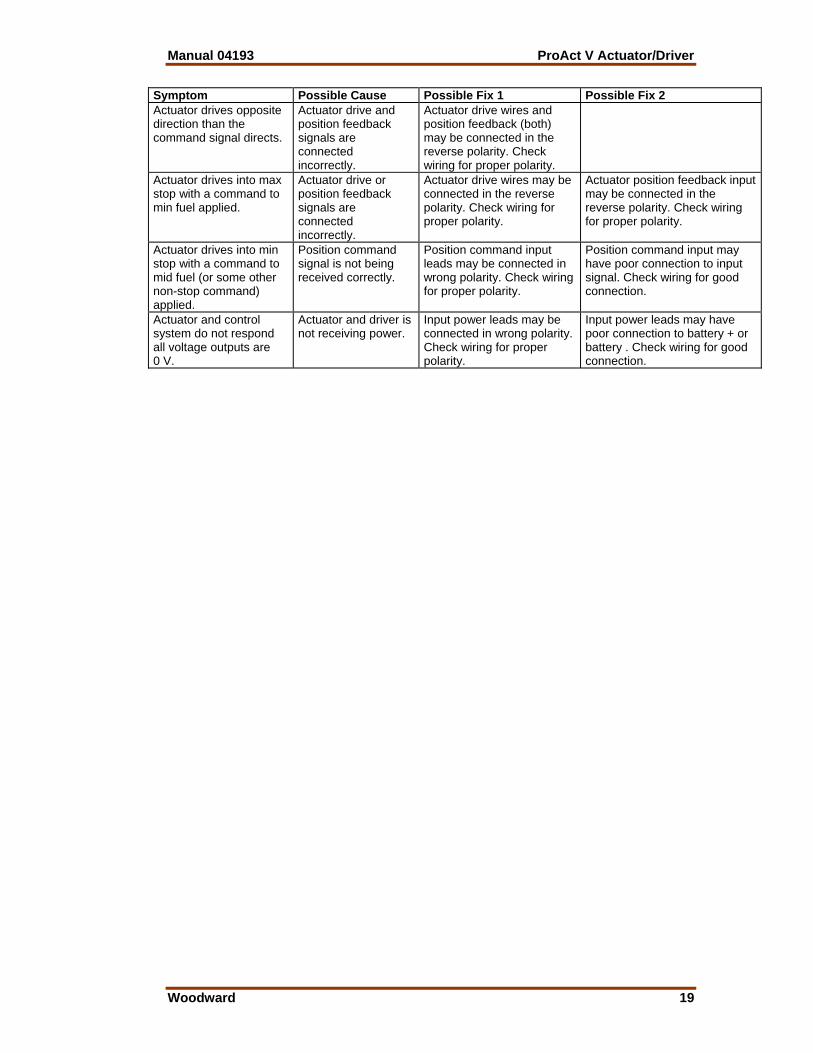
Linkage and Actuator Stroke Use as much of the 70 degrees of actuator stroke as possible. Carefully follow the guidelines in the Actuator Installation section of Chapter 2 in making linkage arrangements. Using less than optimum actuator movement will make stability more difficult, and will make the actuator more sensitive to external loading forces and friction. Possible problems with driver/actuator system include:
Manual 04193 ProAct V Actuator/Driver
Woodward 19
Symptom Possible Cause Possible Fix 1 Possible Fix 2Actuator drives opposite direction than the command signal directs.
Actuator drive and position feedback signals are connected incorrectly.
Actuator drive wires and position feedback (both) may be connected in the reverse polarity. Check wiring for proper polarity.
Actuator drives into max stop with a command to min fuel applied.
Actuator drive or position feedback signals are connected incorrectly.
Actuator drive wires may be connected in the reverse polarity. Check wiring for proper polarity.
Actuator position feedback input may be connected in the reverse polarity. Check wiring for proper polarity.
Actuator drives into min stop with a command to mid fuel (or some other non-stop command) applied.
Position command signal is not being received correctly.
Position command input leads may be connected in wrong polarity. Check wiring for proper polarity.
Position command input may have poor connection to input signal. Check wiring for good connection.
Actuator and control system do not respond all voltage outputs are 0 V.
Actuator and driver is not receiving power.
Input power leads may be connected in wrong polarity. Check wiring for proper polarity.
Input power leads may have poor connection to battery + or battery . Check wiring for good connection.

ProAct V Actuator/Driver Manual 04193
20 Woodward
Chapter 5. Technical Specifications
Power Supply The power supply for the ProAct™ V driver is configured to operate from 18 to 32 Vdc. The minimum current level to be provided by the system will be 10 A dc and 20 A dc for up to 1 second.
Actuator Position Feedback The actuator position feedback output provides a nominal 0.5 to 4.5 Vdc corresponding to 0% to 100% actuator travel for 0–5 V position feedback units and 4–20 mA corresponding to 0% to 100% actuator travel for 4–20 mA position feedback units. The actuator position output has gain and offset adjustments to trim the voltage output for the proper voltages at the correct positions. The maximum load impedance on the 4–20 mA output is 300 Ω.
System Wiring The actuator driver is capable of driving the actuator through wiring harnesses of the following configurations (NOTE–The maximum length of the line distance between the battery, summed with twice the distance between the control and the actuator, must be less than the distance in the following chart.):
Line Length
Driver Wire Gauge
Actuator Position Feedback Wire Gauge
Actuator Position Feedback Wire Type
0—6.7 m (0—22 ft)
4 mm² (12 AWG) or larger stranded
0.5 mm² (20 AWG) or larger stranded
twisted shielded triple
6—10.5 m (20—35 ft)
6 mm² (10 AWG) or larger stranded
0.5 mm² (20 AWG) or larger stranded
twisted shielded triple
10.5—16.8 m (35—55 ft)
8 mm² (8 AWG) or larger stranded
0.5 mm² (20 AWG) or larger stranded
twisted shielded triple
Table 5-1. Wiring Harness Configurations
Under no circumstances should the maximum length calculated using the formula above be greater than 16.8 m (55 ft). In applications where these maximum line lengths are followed, the worst case transient current level at elevated actuator temperatures (100 ºC/212 °F ambient) will be 74% of the transient limit at 20 V supply voltage. This only affects the transient current limits, the steady state limits will still be 10 A. All wiring should also be in accordance with wiring codes for the installation.

Manual 04193 ProAct V Actuator/Driver
Woodward 21
Input Configurations The following input configurations are available for the position command input. PWM–Current Source The PWM input accepts a 100 to 3000 Hz input signal of 7 to 32 V peak voltage (referenced to unit battery ground). This input has an input impedance of 1 kΩ and is designed for a current/voltage sourcing drive. The nominal input of 10% to 90% duty cycle corresponds to 0% to 100% actuator travel (at system calibration temperature). The position command input is capable of providing a common mode input voltage range (unit battery ground referenced) of 0 to 4 V for all inputs. Under some system configurations the common mode range of this circuit can be exceeded. This is typically a fully floating output from the commanding controller. For this reason, the PWM negative input is jumpered to the PWM ground reference at the terminal block inside the ProAct V driver box. See wiring diagram for correct terminal block and pin numbers. PWM–Push-Pull The PWM input accepts a 100 to 3000 Hz input signal of 7 to 32 V peak voltage (referenced to unit battery ground). This input has an input impedance of 21 kΩ and is designed for an active push-pull drive. The nominal input of 10% to 90% duty cycle corresponds to 0% to 100% actuator travel (at system calibration temperature). The position command input is capable of providing a common mode input voltage range (unit battery ground referenced) of 0 to 4 V for all inputs. Under some system configurations the common mode range of this circuit can be exceeded. This is typically a fully floating output from the commanding controller. For this reason, the PWM negative input is jumpered to the PWM ground reference at the terminal block inside the ProAct V driver box. See wiring diagram for correct terminal block and pin numbers. 20–160 mA The 20–160 mA input accepts a 0 to 200 mA dc input. The nominal input of 20 to 160 mA corresponds to 0% to 100% actuator travel (at system calibration temperature). The position command input is capable of providing a common mode input voltage range (unit battery ground referenced) of 0 to 45 V for all inputs. 4–20 mA The 4–20 mA input accepts a 0 to 20 mA dc input. The nominal input of 4 to 20 mA corresponds to 0% to 100% actuator travel (at system calibration temperature). The position command input is capable of providing a common mode input voltage range (unit battery ground referenced) of 0 to 45 V for all inputs.

ProAct V Actuator/Driver Manual 04193
22 Woodward
Low Command Shutdown The ProAct driver is equipped with an actuator drive shutdown that is initiated by an input command signal that is lower than a trip level. When the command input is below the trip level for more than 25 seconds, the drive to the actuator will be shut down. During this period the current draw of the system will be less than 150 mA. During the low command shutdown, no current will be provided to the actuator, and the actuator will not maintain minimum position if it is being forced to maximum fuel by an external force. If a force is required to move the actuator to minimum fuel, the command input must not be allowed to go below the shutdown threshold. The command input can be adjusted to allow minimum fuel to be reached while still maintaining a command level above the trip point. When the command rises above the trip levels, the actuator will be immediately powered up and running in normal mode.
Input type
Low command shutdown trip point
Guaranteed not to shutdown level
PWM input 5% duty cycle 10% 4-20 mA input 1.5 mA 4 mA 0-200 mA input 15 mA 20 mA
Table 5-2. Low Command Shutdown
System Performance The performance of the driver when mated to a ProAct V actuator will be as follows with the system bandwidth potentiometer full counterclockwise: Inertia Level The driver mated to a ProAct V actuator can drive inertial loads not to exceed 0.1 N-m-sec². This is specified as un-damped direct inertia. Actuator Compliance The actuator compliance is identified as: reaching peak steady-state torque in less than 3% of actuator full travel, external deflection of the actuator from commanded position for all supply voltages, and current levels within the specified power supply ranges. Actuator Slew Time The actuator slew time is less than 200 ms for 10% to 90% of rated travel, commanded with the appropriate input square wave for a supply voltage greater than or equal to 24 Vdc, current levels and inertial loads within the specified ranges. For supply voltages less than 24 Vdc, the slew time will be no more than 250 ms.

Manual 04193 ProAct V Actuator/Driver
Woodward 23
Bandwidth–Analog Input (4–20 or 20–160 mA) Versions The bandwidth of the driver for command to position will nominally be between 3 and 4 Hz for the –6 dB point for all supply voltages, current levels, and actuator load inertias within the specified ranges. Position Accuracy The position accuracy for command to position will be better than 1.6% of actuator full travel after the unit has been calibrated to the actuator for gain and offset. This accuracy is valid at the calibration temperature of the actuator assembly. If the actuator assembly temperature is different from the calibration temperature, the position error will be less than ±10.5% of full stroke over the entire temperature range. The temperature deviation is a negative tolerance. This means that the unit will drift such that minimum fuel and maximum fuel are always reachable using the standard input range. However, the unit may reach minimum or maximum fuel at input percentages 10.5% less than (in the case of maximum fuel) or greater than (in the case of minimum fuel) the nominal range. System Protection The system contains protection circuitry to prevent damage if the power supply circuits are connected in reverse polarity. The unit also contains circuitry to prevent driver and actuator damage if one of the actuator wires is short-circuited to battery positive or ground, or if one actuator wire is shorted to the other. The result will be an actuator shutdown during the period of the short circuit. The unit also contains circuitry to prevent driver and actuator damage if the driver steady- state current rises above 10 A continuously. The result will be an actuator shutdown.

ProAct V Actuator/Driver Manual 04193
24 Woodward
Chapter 6. ProAct™ V Driver Detailed Specifications
Driver Regulatory Compliance CE Marking Conforms to EMC Directive 89/336/EEC.
Conformity established by testing to EN 50081-2, EN 50082-2.
Marine Conforms to Lloyd’s Register environment type
ENV3 Pending Type Approval with Germanischer
Lloyd’s application category C
Environmental Specifications Operating Temperature –40 to +70 °C (–40 to +158 °F), uncirculated air,
no external heat loads Storage Temperature –55 to +105 °C (–67 to +221 °F) Component life is adversely affected by high
temperature, high humidity environments. Room temperature storage is recommended for equipment longevity.
Humidity MIL-STD 810D, method 507.3, Procedure 3, (5
cycles 60 °C at 95% RH non- condensing) Lloyd’s environment 3 humidity test 1 (2 cycles
20–55°C at 95% RH non-condensing, over 48 hours)
Salt Fog MIL-STD 810D, method 509.2, 48 hours Vibration MIL-STD 202F, method 214A, Test Condition D,
0.04 G²/Hz Random Vibration, 10–2000 Hz, 3 hr/axis, 8.2 Grms
Lloyd’s environment 3 vibration test 1 (5–13.2
Hz @ ± 1.0 mm; 13.2–100 Hz @ 0.7 g, 10 sweeps per axis at 1 octave/minute)
Shock MIL-STD 810C, method 516.2, Procedure I, 40G
11 ms saw tooth Installation Overvoltage Category Category III Air Quality Pollution degree 3 Ingress Protection In accordance with the requirements of IP56 as
defined in IEC 529
Manual 04193 ProAct V Actuator/Driver
Woodward 25
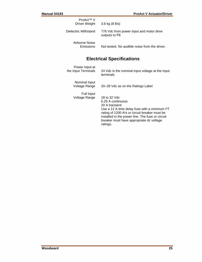
ProAct™ V Driver Weight 3.6 kg (8 lbs) Dielectric Withstand 776 Vdc from power input and motor drive
outputs to PE Airborne Noise Emissions Not tested. No audible noise from the driver.
Electrical Specifications Power Input at the Input Terminals 24 Vdc is the nominal input voltage at the input
terminals Nominal Input Voltage Range 20–29 Vdc as on the Ratings Label Full Input Voltage Range 18 to 32 Vdc 6.25 A continuous 20 A transient Use a 12 A time delay fuse with a minimum I²T
rating of 1200 A²s or circuit breaker must be installed in the power line. The fuse or circuit breaker must have appropriate dc voltage ratings.

ProAct V Actuator/Driver Manual 04193
26 Woodward
Chapter 7. ProAct™ V Actuator Detailed
Specifications
Actuator Regulatory Compliance CE Marking Conforms to EMC Directive 89/336/EEC.
Conformity established by testing to EN 50081-2, EN 50082-2.
Marine Conforms to Lloyd’s Register environment type
ENV4 Pending Type Approval with Germanischer
Lloyd’s application category D
Environmental Specifications Operating Temperature –40 to +100 °C (–40 to +212 °F), uncirculated
air, no external heat loads Storage Temperature –55 to +125 °C (–67 to +221 °F) Humidity Lloyd’s environment 4 humidity test 1 (2 cycles
20–55 °C at 95% RH non-condensing, over 48 hours)
Vibration 0.1 G²/Hz, 10–2000 Hz, 12.8 Grms, random
vibration. 25–300 Hz at 10 G, swept sine Lloyd’s environment 4 vibration test 1 (5–25 Hz
@ ±1.6 mm; 25–100 Hz @ 4.0 g, 10 sweeps per axis at 1 octave/minute)
Shock 40 G peak, 11 ms saw tooth Air Quality Pollution degree 3 Ingress Protection In accordance with the requirements of IP56 as
defined in IEC 529 ProAct™ V Actuator Weight 77 kg (170 lbs) Dielectric Withstand 776 Vdc from motor windings to PE Mass Moment of Inertia 0.0072 N-m-s² (0.0053 lb-ft-s²) max Airborne Noise Emissions Not tested. Audible noises are below a level of
reasonable concern for the safety of operators. Coil Resistance 0.66 Ω

Manual 04193 ProAct V Actuator/Driver
Woodward 27
Chapter 8. Service Options
Product Service Options If you are experiencing problems with the installation, or unsatisfactory performance of a Woodward product, the following options are available: • Consult the troubleshooting guide in the manual. • Contact the manufacturer or packager of your system. • Contact the Woodward Full Service Distributor serving your area. • Contact Woodward technical assistance (see “How to Contact Woodward”
later in this chapter) and discuss your problem. In many cases, your problem can be resolved over the phone. If not, you can select which course of action to pursue based on the available services listed in this chapter.
OEM and Packager Support: Many Woodward controls and control devices are installed into the equipment system and programmed by an Original Equipment Manufacturer (OEM) or Equipment Packager at their factory. In some cases, the programming is password-protected by the OEM or packager, and they are the best source for product service and support. Warranty service for Woodward products shipped with an equipment system should also be handled through the OEM or Packager. Please review your equipment system documentation for details. Woodward Business Partner Support: Woodward works with and supports a global network of independent business partners whose mission is to serve the users of Woodward controls, as described here:
• A Full Service Distributor has the primary responsibility for sales, service, system integration solutions, technical desk support, and aftermarket marketing of standard Woodward products within a specific geographic area and market segment.
• An Authorized Independent Service Facility (AISF) provides authorized service that includes repairs, repair parts, and warranty service on Woodward's behalf. Service (not new unit sales) is an AISF's primary mission.
• A Recognized Engine Retrofitter (RER) is an independent company that does retrofits and upgrades on reciprocating gas engines and dual-fuel conversions, and can provide the full line of Woodward systems and components for the retrofits and overhauls, emission compliance upgrades, long term service contracts, emergency repairs, etc.
• A Recognized Turbine Retrofitter (RTR) is an independent company that does both steam and gas turbine control retrofits and upgrades globally, and can provide the full line of Woodward systems and components for the retrofits and overhauls, long term service contracts, emergency repairs, etc.
A current list of Woodward Business Partners is available at www.woodward.com/support.

ProAct V Actuator/Driver Manual 04193
28 Woodward
Woodward Factory Servicing Options The following factory options for servicing Woodward products are available through your local Full-Service Distributor or the OEM or Packager of the equipment system, based on the standard Woodward Product and Service Warranty (5-01-1205) that is in effect at the time the product is originally shipped from Woodward or a service is performed: • Replacement/Exchange (24-hour service) • Flat Rate Repair • Flat Rate Remanufacture Replacement/Exchange: Replacement/Exchange is a premium program designed for the user who is in need of immediate service. It allows you to request and receive a like-new replacement unit in minimum time (usually within 24 hours of the request), providing a suitable unit is available at the time of the request, thereby minimizing costly downtime. This is a flat-rate program and includes the full standard Woodward product warranty (Woodward Product and Service Warranty 5-01-1205). This option allows you to call your Full-Service Distributor in the event of an unexpected outage, or in advance of a scheduled outage, to request a replacement control unit. If the unit is available at the time of the call, it can usually be shipped out within 24 hours. You replace your field control unit with the like-new replacement and return the field unit to the Full-Service Distributor. Charges for the Replacement/Exchange service are based on a flat rate plus shipping expenses. You are invoiced the flat rate replacement/exchange charge plus a core charge at the time the replacement unit is shipped. If the core (field unit) is returned within 60 days, a credit for the core charge will be issued. Flat Rate Repair: Flat Rate Repair is available for the majority of standard products in the field. This program offers you repair service for your products with the advantage of knowing in advance what the cost will be. All repair work carries the standard Woodward service warranty (Woodward Product and Service Warranty 5-01-1205) on replaced parts and labor. Flat Rate Remanufacture: Flat Rate Remanufacture is very similar to the Flat Rate Repair option with the exception that the unit will be returned to you in “like-new” condition and carry with it the full standard Woodward product warranty (Woodward Product and Service Warranty 5-01-1205). This option is applicable to mechanical products only.

Manual 04193 ProAct V Actuator/Driver
Woodward 29
Returning Equipment for Repair If a control (or any part of an electronic control) is to be returned for repair, please contact your Full-Service Distributor in advance to obtain Return Authorization and shipping instructions. When shipping the item(s), attach a tag with the following information: • return number; • name and location where the control is installed; • name and phone number of contact person; • complete Woodward part number(s) and serial number(s); • description of the problem; • instructions describing the desired type of repair. Packing a Control Use the following materials when returning a complete control: • protective caps on any connectors; • antistatic protective bags on all electronic modules; • packing materials that will not damage the surface of the unit; • at least 100 mm (4 inches) of tightly packed, industry-approved packing
material; • a packing carton with double walls; • a strong tape around the outside of the carton for increased strength.
To prevent damage to electronic components caused by improper handling, read and observe the precautions in Woodward manual 82715, Guide for Handling and Protection of Electronic Controls, Printed Circuit Boards, and Modules.
Replacement Parts When ordering replacement parts for controls, include the following information: • the part number(s) (XXXX-XXXX) that is on the enclosure nameplate; • the unit serial number, which is also on the nameplate.

ProAct V Actuator/Driver Manual 04193
30 Woodward
Engineering Services Woodward offers various Engineering Services for our products. For these services, you can contact us by telephone, by email, or through the Woodward website. • Technical Support • Product Training • Field Service Technical Support is available from your equipment system supplier, your local Full-Service Distributor, or from many of Woodward’s worldwide locations, depending upon the product and application. This service can assist you with technical questions or problem solving during the normal business hours of the Woodward location you contact. Emergency assistance is also available during non-business hours by phoning Woodward and stating the urgency of your problem. Product Training is available as standard classes at many of our worldwide locations. We also offer customized classes, which can be tailored to your needs and can be held at one of our locations or at your site. This training, conducted by experienced personnel, will assure that you will be able to maintain system reliability and availability. Field Service engineering on-site support is available, depending on the product and location, from many of our worldwide locations or from one of our Full-Service Distributors. The field engineers are experienced both on Woodward products as well as on much of the non-Woodward equipment with which our products interface. For information on these services, please contact us via telephone, email us, or use our website and reference www.woodward.com/support, and then Customer Support.
How to Contact Woodward For assistance, call one of the following Woodward facilities to obtain the address and phone number of the facility nearest your location where you will be able to get information and service.
Electrical Power Systems Facility --------------- Phone Number Australia ----------- +61 (2) 9758 2322 Brazil ------------- +55 (19) 3708 4800 China ------------ +86 (512) 6762 6727 Germany: Kempen --- +49 (0) 21 52 14 51 Stuttgart ----- +49 (711) 78954-0 India --------------- +91 (129) 4097100 Japan -------------- +81 (43) 213-2191 Korea--------------- +82 (51) 636-7080 Poland -------------- +48 12 618 92 00 United States----- +1 (970) 482-5811
Engine Systems Facility --------------- Phone Number Australia ----------- +61 (2) 9758 2322 Brazil ------------- +55 (19) 3708 4800 China ------------ +86 (512) 6762 6727 Germany: Stuttgart ----- +49 (711) 78954-0 India --------------- +91 (129) 4097100 Japan -------------- +81 (43) 213-2191 Korea--------------- +82 (51) 636-7080 The Netherlands - +31 (23) 5661111 United States----- +1 (970) 482-5811
Turbine Systems Facility --------------- Phone Number Australia ----------- +61 (2) 9758 2322 Brazil ------------- +55 (19) 3708 4800 China ------------ +86 (512) 6762 6727 India --------------- +91 (129) 4097100 Japan -------------- +81 (43) 213-2191 Korea--------------- +82 (51) 636-7080 The Netherlands - +31 (23) 5661111 United States----- +1 (970) 482-5811
You can also contact the Woodward Customer Service Department or consult our worldwide directory on Woodward’s website (www.woodward.com/support) for the name of your nearest Woodward distributor or service facility. For the most current product support and contact information, please refer to the latest version of publication 51337 at www.woodward.com/publications.

Manual 04193 ProAct V Actuator/Driver
Woodward 31
Technical Assistance If you need to telephone for technical assistance, you will need to provide the following information. Please write it down here before phoning: General Your Name Site Location Phone Number Fax Number Prime Mover Information Engine/Turbine Model Number Manufacturer Number of Cylinders (if applicable) Type of Fuel (gas, gaseous, steam, etc) Rating Application Control/Governor Information Please list all Woodward governors, actuators, and electronic controls in your system: Woodward Part Number and Revision Letter Control Description or Governor Type Serial Number Woodward Part Number and Revision Letter Control Description or Governor Type Serial Number Woodward Part Number and Revision Letter Control Description or Governor Type Serial Number If you have an electronic or programmable control, please have the adjustment setting positions or the menu settings written down and with you at the time of the call.


We appreciate your comments about the content of our publications.
Send comments to: [email protected]
Please reference publication 04193A.
PO Box 1519, Fort Collins CO 80522-1519, USA 1000 East Drake Road, Fort Collins CO 80525, USA Phone +1 (970) 482-5811 • Fax +1 (970) 498-3058
Email and Website—www.woodward.com
Woodward has company-owned plants, subsidiaries, and branches, as well as authorized distributors and other authorized service and sales facilities throughout the world.
Complete address / phone / fax / email information for all locations is available on our website.
2009/4/Fort Collins