Principles - Post-Tensioning Institute Convention/Martter... · The following quotation is from a...
49
1 May 8, 2012 Introduction Most of you know something about the PTI Grade Slab Design Procedure. Many of you have used it for years in your everyday design work. It occupies about 25 pages of the Building Code. It has become the accepted and near-universal method for designing the huge volume of soil-supported grade slab foundations presently constructed on active clay soil. It was originally created by a graduate student at Texas A & M, Prof. Kent Wray, and submitted as his doctoral thesis over 30 years ago. It has been maintained and further developed by an eminent Professor of Geotechnical Science at Texas A & M, Prof. Robert Lytton, whose chosen field of study is the properties of clay soils. With such a pedigree, then, why are engineers in both structural and geotechnical sectors increasingly unhappy with it? The answer, in my opinion, has to do with the philosophical difference between scientists and engineers, and our failure to recognize and allow for that difference. In brief, we took a project, the development of this Design Procedure, that is primarily of an engineering nature, and entrusted it to a group of academics who have the professional outlook of scientists. These men are very good at what they do in the scientific realm, but they do not have the broad outlook necessary for an engineer, particularly with respect to solving practical problems. It is not so much that they have done unsatisfactory work, but rather that we made the wrong choice to begin with. We should have chosen engineers to do the development of an engineering procedure, not scientists. I began doing grade slab design work in Texas 33 years ago, and on travelling back and forth between field and office, I was struck with the thought that the field and office are two different worlds, and that our design process does not accommodate that difference. And that impression is still with me today. The direction of this paper will be to define and explain that difference, and then to suggest a way to bridge the gap. We will begin by putting forth a set of principles on which our arguments will be based. In a sense, these principles are quite obvious, but I think it will be helpful in understanding my direction if you keep them in your thinking as we proceed.
-
Upload
trinhduong -
Category
Documents
-
view
219 -
download
2
Transcript of Principles - Post-Tensioning Institute Convention/Martter... · The following quotation is from a...

1
May 8, 2012
Introduction
Most of you know something about the PTI Grade Slab Design Procedure. Many of you have used it for years in your everyday design work. It occupies about 25 pages of the Building Code. It has become the accepted and near-universal method for designing the huge volume of soil-supported grade slab foundations presently constructed on active clay soil.
It was originally created by a graduate student at Texas A & M, Prof. Kent Wray, and submitted as his doctoral thesis over 30 years ago. It has been maintained and further developed by an eminent Professor of Geotechnical Science at Texas A & M, Prof. Robert Lytton, whose chosen field of study is the properties of clay soils.
With such a pedigree, then, why are engineers in both structural and geotechnical sectors increasingly unhappy with it?
The answer, in my opinion, has to do with the philosophical difference between scientists and engineers, and our failure to recognize and allow for that difference. In brief, we took a project, the development of this Design Procedure, that is primarily of an engineering nature, and entrusted it to a group of academics who have the professional outlook of scientists. These men are very good at what they do in the scientific realm, but they do not have the broad outlook necessary for an engineer, particularly with respect to solving practical problems.
It is not so much that they have done unsatisfactory work, but rather that we made the wrong choice to begin with. We should have chosen engineers to do the development of an engineering procedure, not scientists.
I began doing grade slab design work in Texas 33 years ago, and on travelling back and forth between field and office, I was struck with the thought that the field and office are two different worlds, and that our design process does not accommodate that difference. And that impression is still with me today.
The direction of this paper will be to define and explain that difference, and then to suggest a way to bridge the gap.
We will begin by putting forth a set of principles on which our arguments will be based. In a sense, these principles are quite obvious, but I think it will be helpful in understanding my direction if you keep them in your thinking as we proceed.

2
Principles
1. We must distinguish between science & engineering: - Science is the discovery and measurement of the properties of natural materials. - Engineering takes those discovered properties and puts them to use in practical
applications. - Engineering is science plus the art of application. - We must be careful not to assign an engineering task to a scientific team, and vice
versa. - Science strives to avoid uncertainty. Engineering must accept uncertainty and
grapple with it. “Willingness to cope with imponderables is one thing that separates engineers from scientists, but it is imponderables that can promote failures.”
(Royal Commission Investigation of the Melbourne West Gate Bridge failure)
2. Geotechnical engineering involves working with materials which are usually something of a mixture in their natural state, making their properties difficult to measure accurately. These properties vary widely, and often randomly, within the scope of a single project. Prof. Bowles, in the introduction to his text on foundation design, cautioned that:
“….the reader should realize that foundation loads and soil properties are not likely to be known to a precision closer than ± 10 to 20 percent.”
From there on, it is simple mathematical logic to recognize that if the variable inputs to a procedure have a significant margin of error, we must recognize the consequences of that error in the output of the procedure. Or, as it has been said once or twice before: “garbage in…..garbage out”.
3. A computer program to analyze a physical system is based upon a model of that system. The output of the program is dependent on the model and is no more comprehensive than the model. The computer program analyzes only the system represented by the model, no other system. The model must represent a condition which is dependably consistent and typical. Random activity cannot be modeled.
4. Every engineering procedure which is based upon theory must have experimental
verification before it is accorded validity. The importance of this principle is primary when the engineering is being done in a field in which there are few precedents for comparisons. These are examples: - Nuclear fission in the 1930’s and 1940’s:
“It doesn’t make any difference how smart you are. It doesn’t make any difference how beautiful your theory is. If it isn’t confirmed by experimental results, it is wrong.” (Richard Fineman, American Physicist, Nobel Prize Winner)
- Geotechnical engineering, also in the 30’s, 40’s, & 50’s. The following quotation is from a biography of Karl Terzaghi, who worked during that period. Prof. Terzaghi, as many of you know, has been designated “The Father of
3
Geotechnical Engineering”. He often found himself at odds with academics who never left their desks to investigate and learn from field conditions. He had this to say about them: “Their highest ambition is to faithfully use the rules they have learned, without considering further whether their results are right or wrong.”
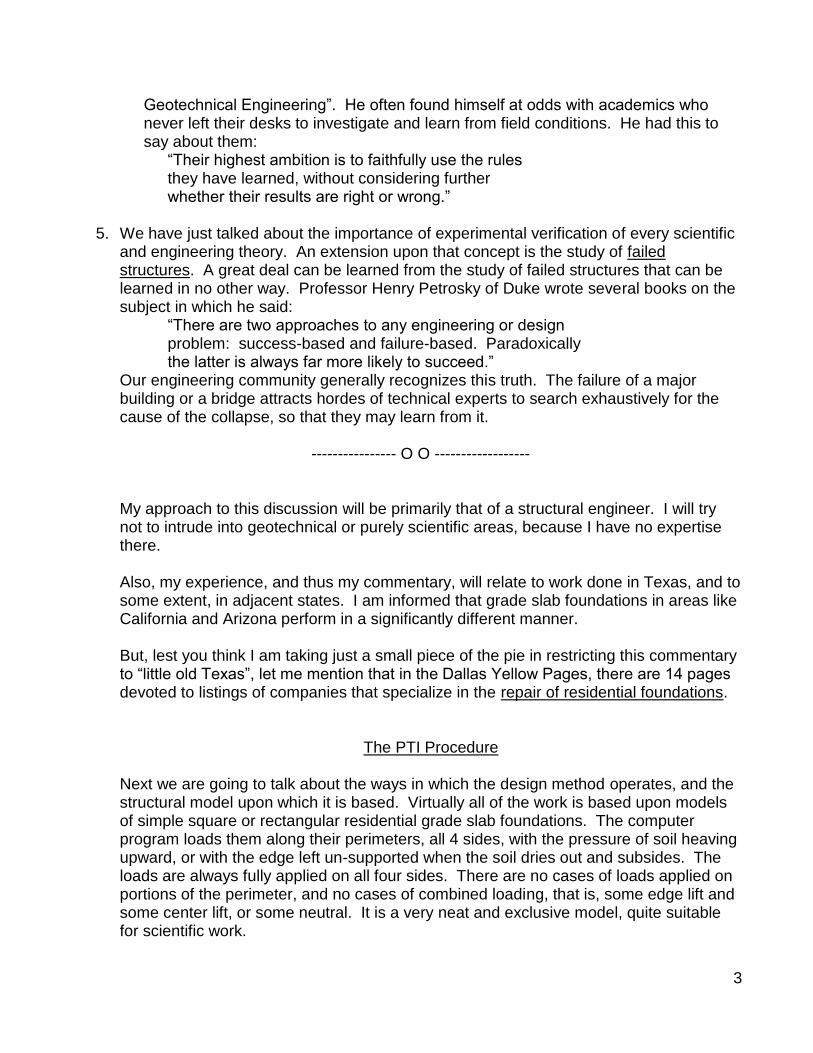
5. We have just talked about the importance of experimental verification of every scientific
and engineering theory. An extension upon that concept is the study of failed structures. A great deal can be learned from the study of failed structures that can be learned in no other way. Professor Henry Petrosky of Duke wrote several books on the subject in which he said:
“There are two approaches to any engineering or design problem: success-based and failure-based. Paradoxically the latter is always far more likely to succeed.”
Our engineering community generally recognizes this truth. The failure of a major building or a bridge attracts hordes of technical experts to search exhaustively for the cause of the collapse, so that they may learn from it.
---------------- O O ------------------
My approach to this discussion will be primarily that of a structural engineer. I will try not to intrude into geotechnical or purely scientific areas, because I have no expertise there.
Also, my experience, and thus my commentary, will relate to work done in Texas, and to some extent, in adjacent states. I am informed that grade slab foundations in areas like California and Arizona perform in a significantly different manner. But, lest you think I am taking just a small piece of the pie in restricting this commentary to “little old Texas”, let me mention that in the Dallas Yellow Pages, there are 14 pages devoted to listings of companies that specialize in the repair of residential foundations.
The PTI Procedure
Next we are going to talk about the ways in which the design method operates, and the structural model upon which it is based. Virtually all of the work is based upon models of simple square or rectangular residential grade slab foundations. The computer program loads them along their perimeters, all 4 sides, with the pressure of soil heaving upward, or with the edge left un-supported when the soil dries out and subsides. The loads are always fully applied on all four sides. There are no cases of loads applied on portions of the perimeter, and no cases of combined loading, that is, some edge lift and some center lift, or some neutral. It is a very neat and exclusive model, quite suitable for scientific work.

4
5
Examples of Inaccurate or Erroneous Engineering in the PTI Grade Slab Design Procedure
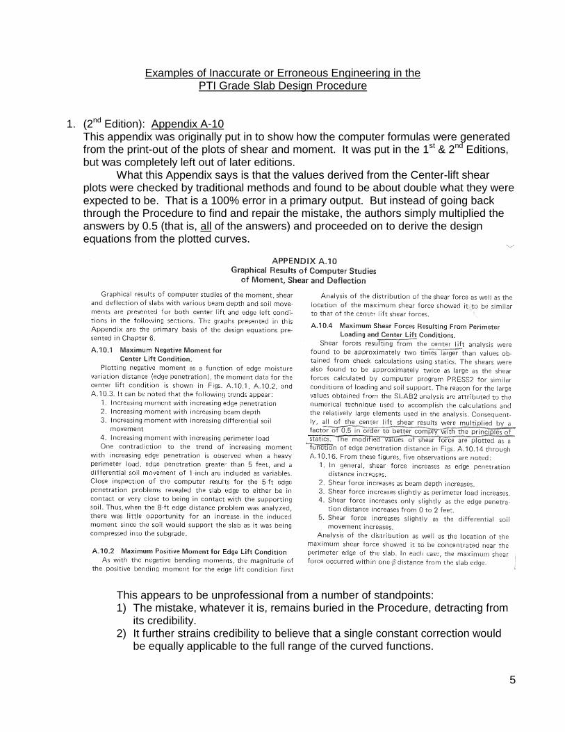
1. (2nd Edition): Appendix A-10 This appendix was originally put in to show how the computer formulas were generated from the print-out of the plots of shear and moment. It was put in the 1st & 2nd Editions, but was completely left out of later editions. What this Appendix says is that the values derived from the Center-lift shear plots were checked by traditional methods and found to be about double what they were expected to be. That is a 100% error in a primary output. But instead of going back through the Procedure to find and repair the mistake, the authors simply multiplied the answers by 0.5 (that is, all of the answers) and proceeded on to derive the design equations from the plotted curves.
This appears to be unprofessional from a number of standpoints: 1) The mistake, whatever it is, remains buried in the Procedure, detracting from
its credibility. 2) It further strains credibility to believe that a single constant correction would
be equally applicable to the full range of the curved functions.

6
3) What about Moment values derived from these curves? Moment and Shear have a dependent relationship. Can moment values be properly generated over a broad range of shear values which were revised with the use of a single constant?
4) Also, we must wonder if this is the level of engineering craftsmanship we can expect, but not observe, in the rest of the Procedure.
This looks like a correction applied with a hammer, when it would have been more appropriate to pause and review the whole Procedure. Observe the equations for center-lift moment. They are ponderous and complex, and would appear to be appropriate products of a well-researched derivation. They do not appear to have been “hammered”.
2. Early on in my use of the Procedure, my attention was caught by the shape of the
various curves showing center-lift moment, specifically Figures 5.1 & 5.3. They show narrow negative moment peaks at the support points. Statics has taught us that such sharp reversals are caused by narrow supports. Just from the shape of the curves, I

7
would guess the supports to be about 1.0 or 2.0 feet wide. Such a situation conflicts with my 30-year-plus experience following the behavior of typical residential slabs on active soils. I have studied many center-heave situations and would “bet the farm” on the typical soil support to be at least 6 to 8 feet wide, and sometimes 10 or 12 feet. For one thing, they would have to be.
The support is composed of a section of damp plastic clay thrusting upward against a very rigid concrete slab soffit. The initially narrow portion of soil thrusting upward would

8
not be able to sustain the elevated bearing pressures and would simply spread out in a much wider support. It would happen quite naturally.
Professor Lytton has said emphatically that the supports he used are not narrow ridges of soil. I would reply with equal emphasis that the computer obviously thinks they are, and that is what counts. The width and the elasticity of the supports also have a direct effect on shear stress. This is of interest because, in the use of the Procedure, shear stress is often a controlling design output. It is of special empirical interest because of the absence, in the field, of any evidence of high shear stresses. In 35 years of high-volume grade slab design work, I have never encountered a crack attributable to shear, nor have any of my colleagues. For an engineering mentality, this is an incomprehensible situation. Why should shear stress be able to control designs, as it often does, by the use of the Design Procedure, when it is never observed in the field? Something here is very wrong. So only one conclusion is possible: The computer program still is giving us erroneously high values of shear stress, even after the stress was reduced to 50% of the original computed value. But now, at least, we know why it is occurring. In a crude but graphic way, the small figure on page 13 of the Third Edition shows how this condition really exists in the field. In center-lift mode, proceeding inward from the edge, the slab above and the soil below gradually come together, the pressure in the soil gradually increases, the vertical load is transferred to the soil over a broad width of the “hump”, and shear stresses are moderate while bending stresses become critical. With plastic soil, it could not be any other way.

9
3. An extension of this thinking may explain something else. The “beta” distance is defined as the approximate distance inward from the edge of the slab to the point of maximum moment. With this concept in mind, as we inspect a slab which is “mal-functioning” in the center-lift mode, why don’t we see a pattern of cracks at or near the beta distance?
Again, I have never seen such a pattern. Invariably, the cracks appear to be randomly located, or usually located in response to some anomaly water source, or water deficiency. But, they seem to have nothing to do with “beta”, that is to say, I question the existence of beta, and thus the validity of the basic model.
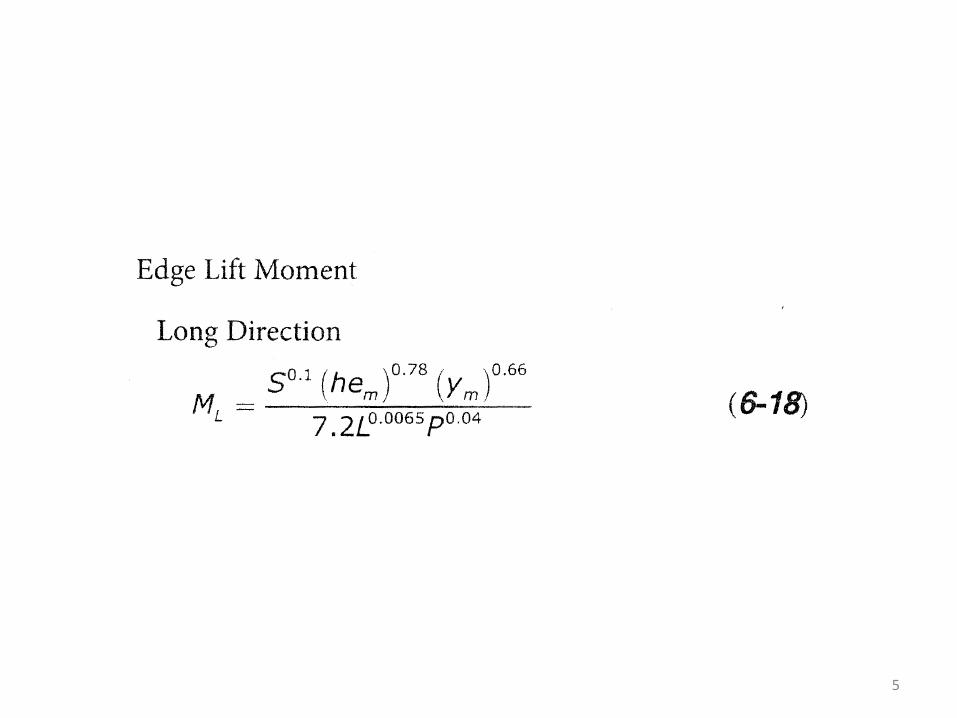
4. At the top of page 37 of the Third Edition, there is a statement with which I thoroughly
agree: “Edge lift moments are difficult to estimate as the soil loading is unknown”.
But if we check Formula 6-18, the basic formula for the calculation of edge lift moments, we find an impressive instrument making use of 6 variable inputs, each with its own highly specific exponential function. Where did this come from if the authors are unable to figure rational loading patterns? It appears that conceptual uncertainty does not prevent them from being numerically specific.
5. In the Third Edition, Em has been given an entirely different derivation from that in previous editions, and they have entirely different derivations. The edge lift and center lift figures have apparently “passed each other in the dark”, one getting larger, while the other usually gets smaller than in previous editions. One wonders how such a conceptual change would be digested by the formulas in which Em is a variable.

10
Professor Lytton’s original idea was that the increase in the size of one would offset the decrease in the other, and the final result would have a negligible change. Of course this did not happen, and there was very little reason to believe it should have happened. Em values are variable inputs in several of the design equations, and in each case carry different exponentials. To think that an offsetting change in their input values would leave the output values of those equations roughly the same would be like throwing darts at a distant sparrow.
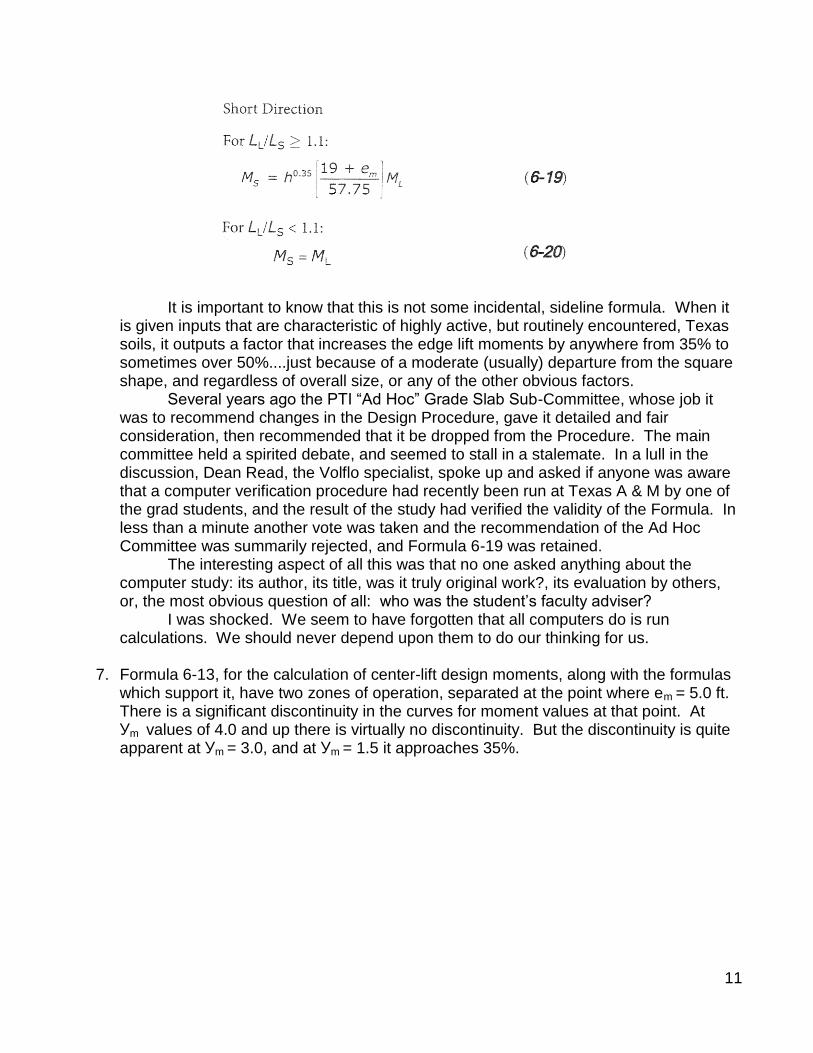
6. Formula 6-19 is a method for figuring the increase in edge-lift design moment in the
short-dimension direction of a rectangular (not square) slab. There is no way to analyze it since it arises magically from the depths of the computer program. But it definitely does not pass the “smell” test. There does not seem to be any reason for the increases which it generates, and experienced engineers are not afraid to look for reasons. If one plays with it and reverses directions a couple of times, it will give results that are just plain foolish.
11
It is important to know that this is not some incidental, sideline formula. When it is given inputs that are characteristic of highly active, but routinely encountered, Texas
soils, it outputs a factor that increases the edge lift moments by anywhere from 35% to sometimes over 50%....just because of a moderate (usually) departure from the square shape, and regardless of overall size, or any of the other obvious factors. Several years ago the PTI “Ad Hoc” Grade Slab Sub-Committee, whose job it was to recommend changes in the Design Procedure, gave it detailed and fair consideration, then recommended that it be dropped from the Procedure. The main committee held a spirited debate, and seemed to stall in a stalemate. In a lull in the discussion, Dean Read, the Volflo specialist, spoke up and asked if anyone was aware that a computer verification procedure had recently been run at Texas A & M by one of the grad students, and the result of the study had verified the validity of the Formula. In less than a minute another vote was taken and the recommendation of the Ad Hoc Committee was summarily rejected, and Formula 6-19 was retained. The interesting aspect of all this was that no one asked anything about the computer study: its author, its title, was it truly original work?, its evaluation by others, or, the most obvious question of all: who was the student’s faculty adviser? I was shocked. We seem to have forgotten that all computers do is run calculations. We should never depend upon them to do our thinking for us.
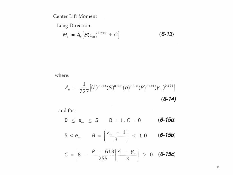
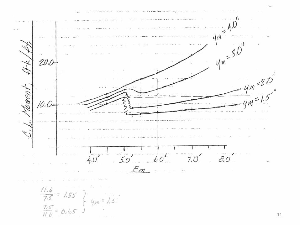
7. Formula 6-13, for the calculation of center-lift design moments, along with the formulas
which support it, have two zones of operation, separated at the point where em = 5.0 ft. There is a significant discontinuity in the curves for moment values at that point. At Уm values of 4.0 and up there is virtually no discontinuity. But the discontinuity is quite apparent at Уm = 3.0, and at Уm = 1.5 it approaches 35%.

12
In the early 1980’s, when I was using the Procedure manually, and had very little experience with the method, I was surprised and disappointed. Such a discontinuity, with no advance warning, and no explanation, was very un-settling. So I called Prof. Kent Wray at his teaching position at Texas Tech in Lubbock. He said: “Oh yes, we discovered that too. We haven’t got a fix for it yet. We are trying to figure it out.”

13
I was further shocked. These respected authorities (Prof.’s Wray and Lytton) had not tested the procedure enough to discover and remediate a glaring discontinuity? (Another puzzle: I was apparently the first person to call in about this. What were the other engineers doing?) Some years later Prof. Wray attended one of our Committee meetings and gave his explanation for the discontinuity. At least it was mechanical and tangible, but the rest was not so good. He said at low values of Уm and higher values of Em, the edge of the slab was never far off the soil, and as the higher Em’s were attained, the end of the slab would sag down and make contact with the soil, which interfered with its free flexure and thus caused the discontinuity. Everyone accepted it and were relieved. But there were two problems I did not figure out until later. One was that the scenario simply could not take place. Start from the beginning when the edge of the slab would be resting on the soil. It would slowly separate as the soil subsided, beginning at the edge and progressing further in, in proportion to the subsidence. The reverse would be simply that: The soil would close the gap starting at the innermost point and progressing outward. There would be no discontinuity, simply a reverse of the original process. Any other scenario for this activity would involve some unusual circumstances which are not part of a typical discussion. The other circumstance which is in conflict with this scenario is that the curves on the far side of the discontinuity do not reflect such a support at the end. They seem to have their normal curved shape, but displaced by the amount of the discontinuity.

14
There is no evidence of a “maverick” support out at the end of the cantilever. So if there was a support there, the computer did not know it. Again, here we seem to have structural procedures which are not at the same level as the geotechnical procedures. 30 years have passed and nothing has been done to correct the mistake, or even admit that it was a mistake.
8. Geotechnical work such as the design of foundations involves working with different
types of soils blended in endlessly variable combinations at random locations subject to the whims of natural forces which have had millions of years and endless supplies of water, wind and seismic activity to mix things up. The geotechnical sector of work is exceeded in the uncertainty of predicted results by perhaps only meteorology or economics.
Geotechnical engineers do recognize this but they do not often give it much emphasis. A quote from a typical Texas geotech report: “Actual soil movement is difficult to predict due
to the many unpredictable variables involved.” Also pertinent (again) is a caution given by Prof. Bowles in the Introduction to his basic text: “Foundation Analysis & Design”: “The reader should realize that foundation loads
and soil properties are not likely to be known to a precision closer than ± 10 or 20 percent.”
Bowles was feeling the dawn of the computer age and went on to say: “….electronic calculators….tend to give a fictitiously high precision to computed quantities.”
Further from a prominent geotechnical engineer: “Geotechnical engineers must become as proficient in statistics and probability as they are in stability analysis and settlement analysis.” (W. Alan Murv, “Using Our Best Judgment”, Civil Engineering, Sept. 2006)
The message from the above authorities is that all thinking with respect to geotechnical problems must accommodate the existence of uncertainty in the range of that put forth by Bowles, and, to be consistent, to follow it through the design procedure with some valid and representative methodology. But our Design Procedure does nothing of the kind.
With a single basic formula or relationship, the problem would not be complex; the effect could even be estimated. But with the PTI Procedures’ multitude of formulas and array of inputs, themselves derived from different aspects of geotech work, the problem is complex and extensive. I would not be surprised if a specialized analysis of the PTI Procedure from the standpoint of statistical accuracy would produce a range of accuracy in the outputs of ± 25%.
A viewpoint with some truth lies in considering the difference between scientists and engineers. Scientists are presently in control of the Procedure, and they are accustomed to presenting problems in sharp, clean environments, with all uncertainty

15
scrubbed off. But foundation design is an engineering problem, and the removal of the uncertainties has seriously distorted the problem, and prevents us from assessing it properly, and working toward a realistic solution.
My view is that the use of a specific performance model is an invalid way to approach the problem, because field performance studies (mine, anyhow) indicate that the model used does not exist.
More on that later.
9. Many valuable lessons about structural performance can be learned only from the observance and analysis of failed structures. In the PTI Manual, there are several references to lessons learned from structural failures, but they are usually offhand and superficial. The emphasis is on lab tests and computer modeling.
It seems to be lost upon the authors of the Procedure that every major Texas city has hundreds (perhaps thousands) of mal-performing residential foundations. Each one offers a special case of a structure pushed to, or beyond, its limits by real-life, not simulated, loading. Also, since we are a segment of industry that probably will not be able to attain much in the way of research funding, two factors appear to be very special:
1) The construction of the homes has already been paid for by others. 2) The owner or the builder will usually pay one of us to go in and take level
readings, measurements and photos, and report upon the results. So we have an enormously valuable resource of malfunctioning structures which someone will pay us to make use of, and we are not doing it, at least in a broad and standardized manner. Kirby Meyer, a respected Austin engineer and an associate of Prof. Lytton’s, has said that it is very difficult to persuade the professors to make a field trip to observe actual field conditions. The authors of the Procedure might make the point that it was set up to respond only to climatic changes, not to maintenance lapses or other environmental or construction anomalies.
In reply to that, we might look at the automobile industry. Basically they design automobiles to run smoothly and efficiently for many thousands of miles. But they also take some of the vehicles off the production lines and subject them to high-speed crash tests. These tests are standardized and the results are recorded and published. And any manufacturer whose autos do not score well in these tests can expect an immediate drop in sales.
If it is important to the buyer of an automobile that it can survive a possible crash, would not the buyer of a home expect it to be designed with consideration of at least some of the anomalies that keep 14 pages of home repairmen listed in the Dallas phone book?
10. We mentioned earlier that the computer program used in the study applies uniform
loads, either upward or downward, and in various magnitudes, to all 4 sides of the chosen rectangle simultaneously. No cases of partial loadings or combined loadings are considered.

16
Such an approach may provide sufficient material for a grad student’s thesis, but it comes up far short of describing real service environments.

17
I have looked at many “challenged” foundations and have never seen one loaded uniformly on all 4 sides. Conditions vary significantly often within 10 feet along the perimeter. Exposure to the sun, drainage, planter areas, and irrigation are some of the influences. It is easy to visualize load combinations which would put critical stresses on the foundation structure, and the number of such combinations is endless. But the uniform load assumption used by the authors is perhaps the least critical of all of them.
Our Design Procedure, then, is simply what it started out to be: a graduate student’s lab study. Nothing more.
11. In the structural design portion of the first issue of the Procedure, there are about 15
significant formulas, some of them with up to 8 input variables, and with exponential modifiers with 2, 3, and even 4 significant figures. These were developed by a young inexperienced grad student at Texas A. & M. (now Prof. Kent Wray) working with limited resources and a relatively primitive computer program. This took place over 30 years ago.
18
In that time period, the Procedure has been put to widespread use, having become the most recommended method for the design of the foundations for light frame buildings on active soils. And it has become recognized and accepted by the IBC. In that 30 year time period, several of the deflection formulas have been eliminated, and there have been several other minor changes. But 11 of the most important formulas have not been changed to the slightest degree. This would appear to be a remarkable, almost un-matched achievement in validity and depth of research. But in reality it is ……..simply paralysis……..an absence of normal development. In the normal state of affairs, a complex brand new Design Procedure, put into use by numerous skilled professionals and subject to healthy examination and discussion, is going to receive and adopt many useful suggestions for fundamental change in the first few years of its lifespan. In the case of the PTI Grade Slab Design Procedure, that has not happened. Some of the reasons are as follows:
1) The core of the work is complex and inter-related; no part of it really stands alone. The complexity actually serves to conceal its inner workings. Therefore it appears to be impractical to attempt to revise it one piece at a time.
2) It is still sponsored by its original creators, who are legitimate and respected authorities in their field, and who continue to aggressively defend it.
3) No one appears to have the time or the resources to suggest or to prepare an entirely new Procedure.
Actually, change does occur rather regularly in the form of new “refinements” by Prof. Lytton in the technology upon which the work is based. However, as with most segments of the Building Codes, the “refinements” are more in the form of “addendums” and the procedure becomes larger and more impenetrable year-by-year.
12. Look back over this whole list. Or better yet, read the PTI Manual. Have you then
heard or read anything about experimental verification of any part of the core of the Procedure? Remember what Prof. Fineman said earlier (Principle No. 4) about un-verified theories?
Intermission
What all of this seems to mean is that the design process has become disconnected from the foundations, and has taken on a life of its own. The process itself has become the product, instead of the foundations. The means has become the end. As we stated earlier, none of the specific “Instances”, by themselves, would serve to invalidate the Procedure. They are meant to illustrate that, in contrast to the “cutting-edge” level of the geotech work which is evident, the level of structural engineering craftsmanship is deficient. In the emphasis upon laboratory work and computer modeling, the necessary “art” of the work has been neglected. However, the following portion of the presentation stands by itself. And its importance is such that it invalidates the entire base of the Procedure, and thus the Procedure itself.

19
The PTI Grade Slab Model
The PTI model for loading and stress distribution has been shown and described earlier. It is an orderly presentation of the stress patterns that would result from uniform perimeter loading. It would be quite suitable for a limited and qualified classroom exercise. The problem is that observations of real foundations under actual service-load conditions show that the critical loads applied by the soil are variable in location and magnitude to the point that they may reasonably be described as “random”. It is true that these loads are influenced by the weather cycle, but they are not “functions” of it. The relationship is not constant or measureable. Other influences, such as drainage and irrigation, appear to have a much more direct and traceable effect on foundation performance, and these things do not occur in an orderly or predictable pattern or schedule, so they cannot be modeled. They are “anomalies”. Webster says an anomaly is a “departure from the regular arrangement, general rule, or usual method”. We believe the concept of an anomaly is central to understanding, working with, and designing residential foundations on active clay soils. It is our position, based upon years of observing and explaining the performance of these foundations, that no two malfunctioning foundations are alike in measureable terms. The foundations may be alike in the general sense that a roomful of people are alike. But each person in that room would react differently to unforeseen combinations of stressful conditions. One “model” would not describe the reaction of each of them. The engineering designer, in advance, cannot describe the specific combination of soil properties, the timing, location, severity, depth, and duration of moisture imbalances, and the effect of defensive measures. If he assumes he can be quantitatively specific about any of these things, much less all of them in concert, he departs from reality, and his assumptions and thus his designs are invalid. It may be said, in defense of the use of the Procedure, that it is solidly based upon a lot of good fundamental science, that its idiosyncrasies have been muffled with various empirical corrections, and that its widespread use over a lengthy period of time is a testament to its validity. However, most professionals would testify that they use it not because they respect it, but because it is almost the only thing out there. It is the best of a bad lot. No one would really feel comfortable using BRAB or WRSI. In Colorado, for instance, the professional society of geotech engineers has prohibited the use of the 3rd Edition.
20
Experienced geotech engineers, who have the most flexibility in using their engineering judgment, regularly revise their Em’s and Ym’s in response to feedback from their structural counterparts. In many cases the early phone call to the structural engineer (or vice versa) has become S.O.P. It gives the structural engineer a chance to input his judgment and his feedback on how various designs are performing in areas that are nearby or have similar soil profiles. At first glance, such a communication would appear to be unnecessary and improper. But it has proven its worth in preventing designs that are too heavy or too light. And the dialogue is beneficial in expanding the experience and empirical base of both parties. However, the gradually increasing recognition of this process raises the question: “….why do we really need the PTI Procedure?” And it is a good question. Older practitioners in this sector, such as myself, clearly remember the days when foundation engineers felt quite comfortable relying on three factors:
1) PVR (based on swell tests) 2) Experience of others in similar areas 3) Soil moisture content at construction.
Actually, in consideration of the above dialogue, we are slowly veering back toward the use of the old system. So that continues to raise the question…..
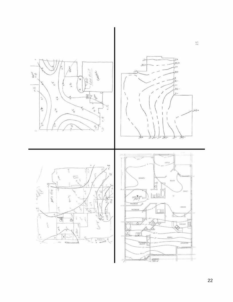
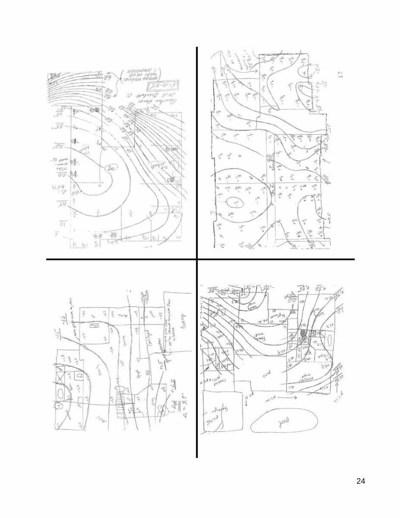
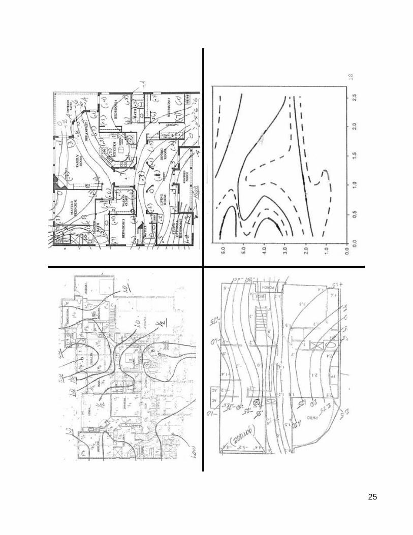
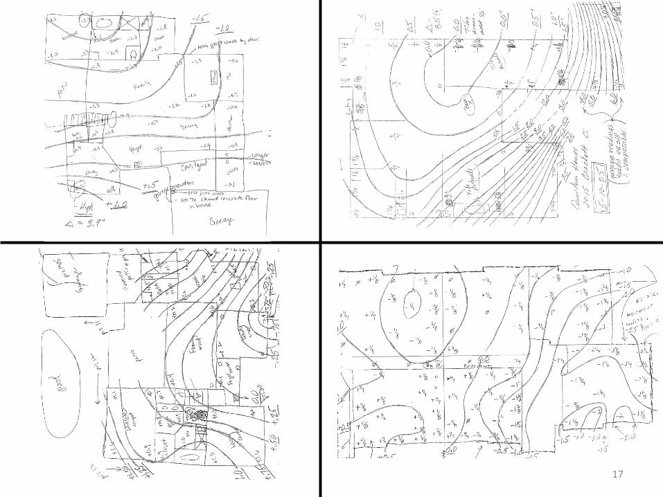
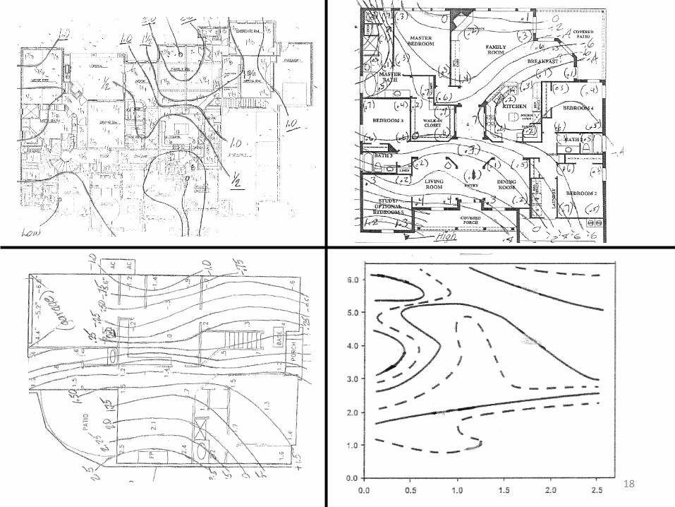
When a homeowner waters his lawn with some consistency, the “weather cycle” no longer exists for that foundation, but the engineer’s responsibility continues, as it should. So when irrigation is irregular or insufficient or absent, that condition should be treated as an anomaly, and the Design Procedure should give the engineer the tools to recognize it and to demonstrate its effect on foundation performance. This is a key all-important position, and it must be supported with pertinent evidence. In that regard I submit the contour maps of the differential elevations on the slab surfaces of twenty typical malfunctioning residential foundations in Texas. Most of them were designed by our firm, probably 80% or 90%, but they were not selected or culled in any technical way. They had only one thing in common: our telephone rang and a voice said: “….please come to look at my foundation…something is going wrong.” These were all the contour maps I could locate in our files. Only two or three were omitted because they were too small or incomplete. My point is that this is a general representative sampling. It is not culled or sorted to represent any point of view. After you have reviewed them, we will resume.
-------------------------- OO --------------------------

21
22

23
24
25

26
It must be noted that the contour maps just reviewed are true elevation contour maps and are thus not directly comparable to the maps (or diagrams) such as Figure 5.2 from the Third Edition which shows the modeled variation in bending moment across the surface of the slab. However, the difference in specifics is inconsequential since one clearly illustrates the academic assumption of orderly activity around the edge of the slab, while the field plans clearly show the random distribution of elevations, and thus the loads and stresses that create them. We believe that the 20 slabs shown constitute a sample of sufficient breadth to support the conclusion that the loading of the soils on the underside of the typical residential slab on active clay soils is an effectively random distribution. It follows no regular or predictable pattern and thus cannot be modeled. Further, the models used for the distribution of loads and stresses in the PTI Procedure (Figure 5.2 et al), being based on the confining and false assumption of continuous and uniform perimeter loading, are inapplicable, non-descriptive, and fallacious. The very purpose of such a model is to closely describe field activity. It if does not do this, it is not only invalid, it becomes dangerously deceptive. Therefore, all the analytical work based upon this model is erroneous. Therefore, the PTI Design Procedure is invalid in principal and execution. (I mentioned earlier that this portion of the presentation would stand by itself.)

27
An Alternative
In selecting a direction for the development of an alternative Design Procedure, I believe our circumstances are similar to those of Prof. Terzaghi, as he contemplated his first definitive work. He proposed to develop a semi-empirical science based on the observed behavior of soils in the field. He mandated:
“As soon as we pass from steel and concrete to earth, the omnipotence of theory ceases to exist.”
As his work progressed and he refined the concept, he wrote: “In Soil Mechanics, the accuracy of computed results never exceeds that of a crude estimate, and the principle function of theory consists in teaching us what and how to observe in the field……hence the center of gravity of research has shifted from the study
and the laboratory into the construction camp where it will remain.”
(fr. “Karl Terzaghi: The Engineer as Artist”)
In endeavoring, then, to select a proper new direction for the development of a Design Procedure, I believe the first step is to resist the urge to construct a model and subject it to analysis. It is a mistake to model a random process, and then attempt to learn specific things from its analysis, and we have made that mistake….twice.
I believe we should develop a systematic method for studying the performance of existing mal-performing foundations, with a standardized method of observing and reporting, so that the results can be archived and collated. We should strive to pinpoint the factors that are most decisive in determining foundation performance. We should use statistical methods in “weighting” those factors and their effect upon designs and performance.
We should maintain a central data bank, preferably at a major university. A small team
of graduate students could maintain the data bank, and develop statistically correct methods for incorporating newly arrived field data into the “bank”.
For the first few years we should be endeavoring to select the factors most important to
foundation performance, focusing on reports of foundations pushed to their limit, or beyond it. After a few years, we should be able to finalize a list of factors to watch…we may
almost be able to do that now. Then our focus could shift to the “weighting” of the various factors. Each year, our review and analysis methods should enable us to “hone” the various weights, and certainly to develop different weight schedules for different geographic areas.
An advantage inherent in this type system is that it would eliminate the type of “mysterious mistakes” that are buried in our present complex Procedure. Mistakes of any type would be easily traceable since the line of logic would be simple and short: “This factor has an effect. Is it more or less than we have been estimating? Should we increase or decrease its

28
weight?” Everything would be available for inspection and evaluation. Nothing would be hidden in the brain of the computer.
Also it would enable us to make at least some use of our engineering experience and
judgment, something for which there is not much room in the present Procedure. The most difficult work, as usual, would be for the geotechnical engineers. They would
be expected to come up with a number which would represent the basic potential of the site for soil movement, something equivalent to our traditional PVR. I might be out of my area of expertise, but to start the discussion, I would say that the number should certainly be based largely upon swell tests, simply because the swell (or shrinkage) of the soil is what we are going to have to design for. But perhaps this new PVR could be modified by some of the more recent work by Prof. Lytton on soil suction and other factors.
A suggestion is that we are presently giving too much attention to the climate moisture
cycle. Homeowners should water their lawns, and when they do, the climate cycle is irrelevant. The Procedure should penalize them only when they do not irrigate, or when they irrigate improperly.
It does appear that there is a yawning gap in our present approach which I believe
needs attention. It is that no one is paying systematic attention to the moisture content of the building pad at the time of construction. Usually it seems possible for a soil sample to be taken in February or March, and construction to commence in August, or next year. It seems to me we should control this in a better way because there seems to be universal agreement that the moisture content of the building pad is an important determinant of soils activity, and thus foundation performance. If we cannot control it, we should at least put allowance for it in our Design Procedure.
The geotech engineer would further be expected to come up with his estimates of the
various “risk factors”, since they would be primarily related to site conditions, and he would be the only one to have seen the site.
However, the structural engineer would be responsible for combining and summarizing
all of the risk factors and he might see a reason for modifying one or several of them. It would be his responsibility to come up with a combined “bottom-line” risk factor with which to modify the basic PVR factor received from the geotech engineer.
After this modification is done, the final modified PVR could be used to select, perhaps
by a graphical means (similar to the PCA pavement design procedure) the beam size and spacing of the final stiffened slab design. An advantage of the graphical method is that it would establish the approximate nature of the Procedure, as opposed to the surgical precision of the present computer output. A sample configuration of a graphical Procedure is enclosed.

29
However, in a practical sense, the weighting of the various factors could be put in algebraic form, and one or several basic equations could probably be sufficient. In the early stages of configuration, there will probably be a number of stages of revision and manipulation, and it will be a lot more convenient to revise some algebraic exponents than to draw new curves every time.
Also, it seems intuitive that the Procedure should not make use of a simple sum of the
“risk factors”. Since the first-considered risk factors would have a primary effect on the design, the effect of succeeding risk factors should be progressively muted, since all would probably not be fully effective at the same time (a little like the “live load reduction” factors). This could easily be done with the application of fractional exponents to the sum of the risk factors. And modified quite easily as we gained experience with the use of the Procedure.
It would be required for the structural engineer to list his assumptions on the foundation
plan so that the builder and owner (and defendant’s legal counsel) might know what was expected of the homeowner.

30
Conclusion
The basic advantage of a Design Procedure of this type is that it seeks to find, and works directly with, the environmental anomaly factors that seem to cause nearly all foundation malfunctions. Most experienced observers report that it is difficult to see the effect of things like fabric factors, gamma numbers, and even Thornthwaite Indexes. We do not deny the existence of such factors, but their effect upon performance is difficult to identify, and thus to predict. It would seem to be a more effective approach to include factors of that type in the calculation of the PVR number, and leave the structural engineers to deal with tangible issues like perimeter drainage, pad moisture, perimeter moisture barriers, nearby trees, negative site slope, irrigation outlook, roof gutters to protect drainage, perimeter grade beam pipe penetrations, fill soils, building configuration and loading, and sensitivity to foundation flexure. If we abandon our present model, which is manifestly irrelevant to observed field activity, we could concentrate on things which actually effect performance. We would directly achieve a better focus of our structural design efforts and investigations. This change of emphasis is no less than the recognition of reality. There is another important advantage which would accrue from this change in direction. Engineers would have a better set of tools with which to defend themselves in frivolous lawsuits. Imagine being able to stand in front of a jury and use a standard calculating Procedure to show the jury the specific numerical effect of ineffective drainage, or some other anomaly. I think the plaintiffs’ lawyers would proceed much more cautiously, if at all. This would not be just a slippery evasion tactic. It would be a forthright presentation of what actually effects foundation performance, a return to reality.
--------------------- O ---------------------

1

2

3

4
5

6

7
8

9

10
11

12

13

14

15

16
17
18

19