Prestressed-Concrete Structure - IN.gov · INDIANA DEPARTMENT OF TRANSPORTATION —2013 DESIGN...
143
INDIANA DEPARTMENT OF TRANSPORTATION—2013 DESIGN MANUAL CHAPTER 406 Prestressed-Concrete Structure Design Memorandum Revision Date Sections Affected 13-11 May 2013 406-1.0 17-08 Apr. 2017 406-6.0, 406-12.10(01)
Transcript of Prestressed-Concrete Structure - IN.gov · INDIANA DEPARTMENT OF TRANSPORTATION —2013 DESIGN...

INDIANA DEPARTMENT OF TRANSPORTATION—2013 DESIGN MANUAL
CHAPTER 406 Prestressed-Concrete
Structure
Design
Memorandum Revision
Date Sections Affected
13-11 May 2013 406-1.0 17-08 Apr. 2017 406-6.0, 406-12.10(01)

Page 2 2013 Indiana Design Manual, Ch. 406
TABLE OF CONTENTS
TABLE OF CONTENTS ................................................................................................................ 2
LIST OF FIGURES ........................................................................................................................ 4
406-1.0 GENERAL [Rev. May 2013] ........................................................................................... 7
406-2.0 DEFINITIONS ................................................................................................................. 7
406-3.0 NOTATIONS ................................................................................................................... 7
406-4.0 MATERIAL PROPERTIES ............................................................................................. 7 406-4.01 General ....................................................................................................................... 7 406-4.02 Normal-Weight and Lightweight Concrete [Rev. Oct. 2012] .................................... 7
406-4.02(01) Shrinkage and Creep ........................................................................................ 8 406-4.02(02) Modulus of Elasticity, Poisson’s Ratio, and Modulus of Rupture ................... 8
406-4.03 Lightweight Concrete [Rev. Oct. 2012] ..................................................................... 9 406-4.04 Prestressing Steel ........................................................................................................ 9 406-4.05 Post-Tensioning Anchorage and Couplers ................................................................. 9 406-4.06 Ducts ......................................................................................................................... 10
406-5.0 LIMIT STATES ............................................................................................................. 11 406-5.01 General ..................................................................................................................... 11 406-5.02 Service-Limit State ................................................................................................... 11 406-5.03 Fatigue-Limit State ................................................................................................... 11 406-5.04 Strength-Limit State ................................................................................................. 11 406-5.05 Extreme-Event-Limit State ....................................................................................... 11
406-6.0 DESIGN CONSIDERATIONS, FLEXURE AND AXIAL FORCE EFFECTS [Rev. Apr. 2017] ................................................................................................................................. 12
406-7.0 SHEAR AND TORSION ............................................................................................... 12 406-7.01 General ..................................................................................................................... 12 406-7.02 Sectional-Design Model ........................................................................................... 13 406-7.03 Interface Shear Transfer – Shear Friction ................................................................ 13 406-7.04 Segmental Concrete Bridge ...................................................................................... 13
406-8.0 PRESTRESSED CONCRETE ....................................................................................... 14 406-8.01 General Considerations and Stress Limitations ........................................................ 14 406-8.02 Loss of Prestress ....................................................................................................... 14
406-9.0 PRESTRESSING-REINFORCEMENT REQUIREMENTS ......................................... 14 406-9.01 Spacing of Prestressing Tendons and Ducts ............................................................. 14 406-9.02 Tendon Confinement and Effects of Curved Tendons ............................................. 15

2013 Indiana Design Manual, Ch. 406 Page 3
406-9.03 Post-Tensioned and Pretensioned Anchorage Zone ................................................. 15
406-10.0 DEVELOPMENT OF PRESTRESSING STRANDS AND DEBONDING ............... 15
406-11.0 DIAPHRAGMS ............................................................................................................ 16 406-11.01 General Requirements ............................................................................................ 16 406-11.02 Intermediate Diaphragms ....................................................................................... 16 406-11.03 Structural-Steel and Reinforced-Concrete Interior Diaphragms ............................ 17 406-11.04 End Diaphragms ..................................................................................................... 17 406-11.05 Interior Pier or Bent Diaphragms ........................................................................... 18
406-12.0 ADDITIONAL DESIGN FEATURES ........................................................................ 19 406-12.01 General ................................................................................................................... 19 406-12.02 Prestressed-Concete-Member Sections .................................................................. 19
406-12.02(01) General ......................................................................................................... 19 406-12.02(02) AASHTO I-Beam Type I, II, III, or IV ........................................................ 19 406-12.02(03) Indiana Bulb-Tee Beam [Rev. Oct. 2012] ................................................... 20 406-12.02(04) Indiana Composite or Non-Composite Box Beam ...................................... 20
406-12.03 Strand Configuration and Mild-Steel Reinforcement ............................................. 21 406-12.03(01) General ......................................................................................................... 21 406-12.03(02) Prestressing-Strands Configuration.............................................................. 21 406-12.03(03) Mild-Steel Reinforcement ............................................................................ 22
406-12.04 Stage Loading for Pretensioned Construction ........................................................ 23 406-12.04(01) Strands Tensioned in the Stressing Bed ....................................................... 23 406-12.04(02) Strands Released and Force Transferred to the Concrete ............................ 23 406-12.04(03) Camber Growth and Prestress Losses .......................................................... 23 406-12.04(04) Maximum Service Load, Minimum-Prestress Stage ................................... 24
406-12.05 Continuity for Superimposed Loads ....................................................................... 24 406-12.06 Effect of Imposed Deformations ............................................................................ 25 406-12.07 Transverse Connection of Precast Box Beams ....................................................... 26 406-12.08 Segmental Construction .......................................................................................... 26 406-12.09 Dimensioning Precast Beams ................................................................................. 27 406-12.10 Other Design Features ............................................................................................ 28
406-12.10(01) Skew [Rev. Apr. 2017] ................................................................................ 28 406-12.10(02) Shortening of Superstructure ....................................................................... 29
406-13.0 AASHTO I-BEAMS..................................................................................................... 29
406-14.0 INDIANA BULB-TEE BEAMS .................................................................................. 29
406-15.0 INDIANA COMPOSITE AND NON-COMPOSITE BOX BEAMS .......................... 29
406-16.0 MISCELLANEOUS DETAILS ................................................................................... 29
FIGURES ...................................................................................................................................... 30

Page 4 2013 Indiana Design Manual, Ch. 406
LIST OF FIGURES Figure Title 406-12A Adjacent Box Beams with Transverse Tensioning Rods (Section View) 406-12B Dimensioning Prestressed-Concrete Beam on Slope 406-13A I-Beam Type I 406-13B I-Beam Type II 406-13C I-Beam Type III 406-13D I-Beam Type IV 406-14A Bulb-Tee Beam Type BT 54 x 48 406-14B Bulb-Tee Beam Type BT 60 x 48 406-14C Bulb-Tee Beam Type BT 66 x 48 406-14D Bulb-Tee Beam Type BT 72 x 48 406-14E Bulb-Tee Beam Type BT 78 x 48 406-14F Bulb-Tee Beam Type BT 84 x 48 Section 406-14G Bulb-Tee Beam Type BT 36 x 49 Sections Showing Prestressing and Mild 406-14H Bulb-Tee Beam Type BT 42 x 49 Sections Showing Prestressing and Mild
Reinforcing Steel 406-14 I Bulb-Tee Beam Type BT 48 x 49 Sections Showing Prestressing and Mild
Reinforcing Steel 406-14 J Bulb-Tee Beam Type BT 54 x 49 Sections Showing Prestressing and Mild
Reinforcing Steel 406-14K Bulb-Tee Beam Type BT 60 x 49 Sections Showing Prestressing and Mild
Reinforcing Steel 406-14L Bulb-Tee Beam Type BT 66 x 49 Sections Showing Prestressing and Mild
Reinforcing Steel 406-14M Bulb-Tee Beam Type BT 54 x 60 406-14N Bulb-Tee Beam Type BT 60 x 60 406-14 O Bulb-Tee Beam Type BT 66 x 60 406-14P Bulb-Tee Beam Type BT 72 x 60 406-14Q Bulb-Tee Beam Type BT 78 x 60 406-14R Bulb-Tee Beam Type BT 84 x 60 406-14S Wide Bulb-Tee Beam Type BT 36 x 61 Sections Showing Prestressing and Mild 406-14T Wide Bulb-Tee Beam Type BT 42 x 61 Sections Showing Prestressing and Mild
Reinforcing Steel 406-14U Wide Bulb-Tee Beam Type BT 48 x 61 Sections Showing Prestressing and Mild
Reinforcing Steel 406-14V Wide Bulb-Tee Beam Type BT 54 x 61 Sections Showing Prestressing and Mild
Reinforcing Steel

2013 Indiana Design Manual, Ch. 406 Page 5
406-14W Wide Bulb-Tee Beam Type BT 60 x 61 Sections Showing Prestressing and Mild Reinforcing Steel
406-14X Wide Bulb-Tee Beam Type BT 66 x 61 Sections Showing Prestressing and Mild Reinforcing Steel
406-14Y Bulb-Tee Beam Elevations Showing End Reinforcement 406-14Z Bulb-Tee Beam Section at End Showing Draped Strands 406-15A Box Beam Type CB 12 x 36 406-15B Box Beam Type CB 17 x 36 406-15C Box Beam Type CB 21 x 36 406-15D Box Beam Type CB 27 x 36 406-15E Box Beam Type CB 33 x 36 406-15F Box Beam Type CB 42 x 36 406-15G Box Beam Type CB 12 x 48 406-15H Box Beam Type CB 17 x 48 406-15 I Box Beam Type CB 21 x 48 406-15J Box Beam Type CB 27 x 48 406-15K Box Beam Type CB 33 x 48 406-15L Box Beam Type CB 42 x 48 406-15M Box Beam Type WS 12 x 48 406-15N Box Beam Type WS 17 x 48 406-15 O Box Beam Type WS 21 x 48 406-15P Box Beam Type WS 27 x 48 406-15Q Box Beam Type WS 33 x 48 406-15R Box Beam Type WS 42 x 48 406-16A I-Beam Pier Diaphragm, Section Between Beams 406-16B I-Beam Pier Diaphragm, Section at Beams 406-16C I-Beam Intermediate Diaphragm 406-16D I-Beam Diaphragms 406-16E I-Beam: End Bent Cap Sizing and Bearing Layout Details 406-16F I-Beam: Pier Cap Sizing and Bearing Layout Details 406-16G I-Beam: Holes at Pier Diaphragm 406-16H Bulb-Tee Pier Diaphragm, Section Between Beams 406-16 I Bulb-Tee Pier Diaphragm, Section at Beams 406-16J Bulb-Tee Intermediate Diaphragm 406-16K Bulb-Tee Diaphragm 406-16L Bulb-Tee: End Bent Cap Sizing and Bearing Layout Details 406-16M Bulb-Tee: Pier Cap Sizing and Bearing Layout Details 406-16N Bulb-Tee: Holes at Pier Diaphragm 406-16 O Box Beam Pier Diaphragm for Spread Beams, Section Between Beams 406-16P Box Beam Pier Diaphragm for Spread Beams, Section at Beams 406-16Q Box Beam Diaphragm at Pier

Page 6 2013 Indiana Design Manual, Ch. 406
406-16R Box Beam Closure Pour at Pier for Adjacent Beams 406-16S Box Beam: End Bent Cap Sizing and Bearing Layout Details 406-16T Box Beam: Pier Cap Sizing and Bearing Layout Details for Spread Beams 406-16U Box Beam: Pier Cap Sizing and Bearing Layout 406-16V Box Beam Inserts at Pier Diaphragm 406-16W Mild Reinforcement for 36-in Width Skewed-Beam End (45-deg Skew Shown) 406-16X Mild Reinforcement for 48-in Width Skewed-Beam End (45-deg Skew Shown)

2013 Indiana Design Manual, Ch. 406 Page 7
CHAPTER 406
PRESTRESSED CONCRETE 406-1.0 GENERAL [REV. MAY 2013] The requirements of this Chapter will apply to each bridge designed with normal or lightweight concrete reinforced with prestressed or post-tensioned strands. Partial prestressing is not permitted. The requirements described herein are based on a 28-day concrete strength, cf ′ , of 4 to 8 ksi. 406-2.0 DEFINITIONS See LRFD 5.2. 406-3.0 NOTATIONS See LRFD 5.3. 406-4.0 MATERIAL PROPERTIES 406-4.01 General The material properties cited herein are based on the construction materials specified in LRFD 5.4. The minimum acceptable properties and test procedures shall be specified in the contract documents. 406-4.02 Normal-Weight and Lightweight Concrete [Rev. Oct. 2012] The minimum cf ′ for prestressed or post-tensioned concrete components shall be shown on the plans. Such a strength outside the range shown in Section 406-1.0 is not permitted without written approval of the Director of Bridges. For lightweight concrete, the air dry unit weight shall be shown on the plans as 119 lb/ft3. The modulus of elasticity will be calculated using the 119 lb/ft3 value. The unit weight of the lightweight concrete will be taken as 124 lb/ft3. The

Page 8 2013 Indiana Design Manual, Ch. 406
additional weight is to account for the mild reinforcing steel and the tensioning strands. See LRFD 5.4.2.2 for the coefficient of linear expansion. The following will apply to concrete. 1. The design compressive strength of normal-weight and lightweight concrete at 28 days,
cf ′ , shall be in the range as follows:
a. prestressed box beam: 5 to 7 ksi b. prestressed I-beam: 5 to 7 ksi c. prestressed bulb-tee beam: 6 to 8 ksi
An exception to the range shown above will be allowed for a higher strength if the higher strength can be documented to be of significant benefit to the project, it can be effectively produced, and approval is obtained from the Director of Bridges.
2. At release of the prestressing strands, cf ′ shall not be less than 4 ksi, and shall be
determined during the beam design. The specified concrete compressive strength at release shall be rounded to the next higher 0.1 ksi.
406-4.02(01) Shrinkage and Creep Losses due to shrinkage and creep, for other than than a segmentally-constructed bridge, that require a more-precise estimate including specific materials, structural dimensions, site conditions, construction methods, and age at various stages of erection, can be estimated by means of the methods specified in LRFD 5.4.2.3.2 and 5.4.2.3.3. Other acceptable methods are those described in the CEB-FIP 1978 / 1990 code. The annual average ambient relative humidity shall be taken as 70%. 406-4.02(02) Modulus of Elasticity, Poisson’s Ratio, and Modulus of Rupture The modulus of elasticity shall be calculated as specified in LRFD Eqn. 5.4.2.4-1. Poisson’s ratio shall be taken as 0.2. See LRFD 5.4.2.6 for modulus-of-rupture values depending on whether the concrete is normal weight or lightweight, and whether the intended application is control of cracking, deflection, camber, or shear resistance.

2013 Indiana Design Manual, Ch. 406 Page 9
406-4.03 Lightweight Concrete [Rev. Oct. 2012] The use of lightweight concrete, with normal-weight sand mixed with lightweight coarse aggregate, is permitted with a specified density of 119 lb/ft3. The use of lightweight concrete shall be demonstrated to be necessary and cost effective during the structure-size-and-type study. The modulus of elasticity will be less than that for normal-weight concrete. Creep, shrinkage, and deflection shall be appropriately evaluated and accounted for if lightweight concrete is to be used. The formula shown in LRFD 5.4.2.6 shall be used in lieu of physical test values for modulus of rupture. The formula for sand-lightweight concrete shall be used for lightweight concrete. 406-4.04 Prestressing Steel Prestressing strands shall be of the low-relaxation type with a minimum tensile strength of 270 ksi. Unless there is a reason to do otherwise, only the following three-strand diameters shall be used. 1. Nominal 3/8 in., As = 0.085 in2, for use in a stay-in-place deck panel. 2. Nominal 1/2 in., As = 0.167 in2, for use in an I, bulb-tee, or box beam, or post-tensioned
member. 3. Nominal 0.6 in., As = 0.217 in2, for use in a in a bulb-tee beam or post-tensioned member. See LRFD Table 5.4.4.1-1 for values of yield strength, tensile strength, and modulus of elasticity of prestressing strands or bars. Prestressing threadbars are used for grouted construction. If the bars are used for permanent non-grouted construction, the bars shall be epoxy coated. 406-4.05 Post-Tensioning Anchorage and Couplers See LRFD 5.4.5 regarding the use of anchorages or couplers. Tendons, anchorages, end fittings, and couplers shall be protected against corrosion. If couplers are used to connect bars, they shall be enclosed in duct housings long enough to permit the necessary movement.

Page 10 2013 Indiana Design Manual, Ch. 406
406-4.06 Ducts See LRFD 5.4.6 for types of ducts, radius-of-curvature limits, general considerations for tendons, and size requirements. Polyethylene ducts shall be used in a corrosive environment such as in a bridge deck or in a substructure element under a joint. The contract documents shall indicate the type of duct material to be used. Ducts for a post-tensioned bulb-tee beam shall be of round, semi-rigid, galvanized-metal. The wall thickness shall not be less than 28 gage. A radius that requires prebending shall be avoided if possible. If the bridge is to be constructed by means of post-tensioning precast components together longitudinally or transversely by use of a cast-in-place concrete joint, the end of each duct shall be extended beyond the concrete interface for not less than 3 in. and not more than 6 in. to facilitate joining the ducts. If necessary, the extension can be in a local blockout at the concrete interface. Joints between sections of ducts shall be positive metallic connections, which do not result in angle changes at the joints. The plans shall show all pertinent geometry required for development of working drawings with the correct tendon alignment in both elevation and plan views. This includes anchorage regions and areas where there are tight or reverse curvatures of the the tendons. Curved ducts that run parallel to each other or around a void or re-entrant corner shall be encased in concrete and reinforced as necessary to avoid radial failure, or pullout into another duct or void. Upon completion of post-tensioning, the ducts shall be grouted. Ducts or anchorage assemblies for post-tensioning shall be provided with a pipe or other suitable connection at each end for the injection of grout after prestressing. A duct of over 200 ft in length shall be in accordance with the recommendations of the PTI. Vents shall be ½-in. minimum diameter standard pipe or suitable plastic pipe. Connections to the ducts shall be made with metallic or plastic fasteners. Plastic components, if selected and approved, shall not react with the concrete or enhance corrosion of the prestressing steel, and shall be free of water-soluble chlorides. The vents shall be mortar tight, taped as necessary, and shall provide means for injection of grout through the vents and for positive sealing of the vents. Ends of steel vents shall be removed at least 1 in. below the concrete deck surface, if appropriate, after the grout has set. Ends of plastic vents shall be removed to the surface of the concrete after the grout has set.
2013 Indiana Design Manual, Ch. 406 Page 11
Grout injection pipes shall be fitted with positive mechanical shut-off valves. Vents and ejection pipes shall be fitted with valves. Caps shall not be removed or opened until the grout has set. 406-5.0 LIMIT STATES 406-5.01 General In addition to service, fatigue, strength, and extreme-event limit states, prestressed or post-tensioned components shall be investigated for stresses and deformations for each critical stage during construction, stressing, handling, transportation, and erection. 406-5.02 Service-Limit State See LRFD 5.7.3.4 for control of cracking, 5.7.3.6 for deformations, and 5.9.4 for stress limits for concrete. 406-5.03 Fatigue-Limit State See LRFD 5.5.3.1 to determine if fatigue shall be considered. Use the stress ranges for prestressing tendons provided in LRFD 5.5.3.3 if necessary. 406-5.04 Strength-Limit State See LRFD 5.5.4.2 and Table 5.5.4.2.2-1 for resistance factors for tension-controlled, compression-controlled, or transition prestressed concrete sections, shear, torsion, or anchorage zones. For segmental construction, the resistance factors shall be modified for flexure and shear accordingly. See LRFD 5.5.4.3 for required stability checks. 406-5.05 Extreme-Event-Limit State See LRFD 5.4.6.2 and Table 3.4.1-1.

Page 12 2013 Indiana Design Manual, Ch. 406
406-6.0 DESIGN CONSIDERATIONS, FLEXURE AND AXIAL FORCE EFFECTS [REV. APR. 2017] See LRFD 5.6.3 and 5.10.9.4 for a strut-and-tie model overview that can be used in the design of an anchorage zone, deep beam, bracket, or corbel. The assumptions for service, fatigue, strength, and extreme-event-limit states are described in LRFD 5.7.1. Strength equations provided in LRFD 5.7.2 are based on the rectangular-stress-block approach. For stress calculations in prestressing steel at nominal flexure resistance, the equations for components with bonded and unbonded tendons provided in LRFD 5.7.3.1.1 and 5.7.3.1.2 are acceptable. For components with both bonded and unbonded tendons, the simplified analysis provided in LRFD 5.7.3.1.3b is acceptable. The flexural resistance may be computed with the equations provided in LRFD 5.7.3.2, or a more-precise calculation can be used as described in LRFD 5.7.3.2.5. The amount of prestressed tensile reinforcement is limited by the minimum reinforcement requirements provided in LRFD 5.7.3.3.2. There is not a limitation in LRFD 5.7.4.2 for maximum prestressed tensile reinforcement for flexural members. For compression members, the maximum and minimum reinforcement requirements provided in LRFD 5.7.4.2 are applicable. Slenderness effects, computation of factored axial resistance, and biaxial flexure effects provided in LRFD 5.7.4.4 are applicable to prestressed concrete columns. Instantaneous deflections, long-term deflections, and cambers shall be computed with the modulus of elasticity, moment of inertia, and cracking moment specified in LRFD 5.7.3.6.2. The methods provided therein to obtain long term deflections from instantaneous deflections are acceptable. 406-7.0 SHEAR AND TORSION 406-7.01 General LRFD 5.6.3 allows the strut-and-tie model and the sectional-design model for shear design of prestressed concrete,. In a region near a discontinuity, the strut-and-tie model shall be used. The sectional-design model is appropriate for the design of a girder, slab, or other region of components where the assumptions of traditional beam theory are valid. See LRFD 5.8.3 and PCI Bridge Design Manual Section 8.12 for more information regarding the strut-and-tie model.

2013 Indiana Design Manual, Ch. 406 Page 13
Torsional effects shall be investigated only if the condition in LRFD 5.8.2.1 for normal weight concrete, or slightly modified for lightweight concrete, is satisfied. If necessary, the torsional resistance obtained with the sectional-design model is provided in LRFD 5.8.2.2. Transverse reinforcement, minimum and maximum requirements, types of transverse reinforcement, and shear stresses of concrete are provided in LRFD 5.8.2.4. They shall be satisfied in the design. These are complemented by LRFD 5.8.2.9 for a segmental post-tensioned concrete box-girder bridge. 406-7.02 Sectional-Design Model LRFD 5.8.3 discusses the sectional-design model. The general formulas used to calculate the nominal shear resistance are shown in LRFD 5.8.3.3-1. The parameters used to evaluate these expressions depend on the adopted approach. For a prestressed-concrete structure, the use of either the modified-compression field theory or the simplified procedure is acceptable. In order to account for the tension caused by shear, the longitudinal-reinforcement requirements shown in LRFD 5.8.3.6.3 shall be satisfied for sections subjected to combined shear and torsion. 406-7.03 Interface Shear Transfer – Shear Friction A cast-in-place concrete deck designed to act compositely with precast-concrete beams shall be able to resist the horizontal shearing forces at the interface between the two elements. LRFD 5.8.4.1 discusses the requirements for shear transfer. The nominal shear resistance of the interface and the factored interface shear force are provided in LRFD 5.8.4.2. The most appropriate condition of the interaction between concrete-slab and concrete-girder surfaces shall be selected individulally from the six situations of cohesion and friction factors provided in LRFD 5.8.4.3. The requirement for minimum area of interface shear reinforcement provided in LRFD 5.8.4.4 shall be satisfied. 406-7.04 Segmental Concrete Bridge LRFD 5.8.5 states that principal stresses determined using classic beam theory and the principles of Mohr’s circle and local tensions in the web from anchorage of tendons shall be investigated. The principal tensile stress shall not exceed the tensile stress limits shown in LRFD Table 5.9.4.2.2-1.

Page 14 2013 Indiana Design Manual, Ch. 406
The shear and torsion requirements shown in LRFD 5.8.3.6 supersede those for the design of a segmental post-tensioned concrete box girder bridge. LRFD 5.8.2 applies, but with the modifications shown in LRFD 5.8.3 through 5.8.5. 406-8.0 PRESTRESSED CONCRETE 406-8.01 General Considerations and Stress Limitations General requirements for design, concrete strength, buckling, section properties, crack control, location of tendon relative to the duct, and stresses due to imposed deformations are provided in LRFD 5.9.1. Contrary to the LRFD requirements, INDOT does not allow a transformed section for a pretensioned member. The stress limitations for prestressing tendons, deformed high-strength bars, and concrete before and after losses have occurred, are provided in LRFD 5.9.3. 406-8.02 Loss of Prestress Total prestress losses in a member constructed and prestressed in a single stage are provided in LRFD 5.9.5.1. The losses are defined as instantaneous losses such as anchorage set, friction, elastic shortening, and time-dependent losses. The acceptable methods provided for determining the time-dependent losses are an approximate and a refined method. The refined method can be used for the final design of a nonsegmental prestressed concrete member. For a post-tensioned concrete member with multistage construction or prestressing, the prestress losses shall be computed by means of a time-dependent-analysis method such as that described in CEB-FIP (1978 / 1990). The approximate lump-sum estimate method shall be used for preliminary design only. The values of the wobble and curvature friction coefficients, and the anchor-set loss assumed for the design shall be shown on the plans. 406-9.0 PRESTRESSING-REINFORCEMENT REQUIREMENTS 406-9.01 Spacing of Prestressing Tendons and Ducts

2013 Indiana Design Manual, Ch. 406 Page 15
The minimum and maximum spacing of pretensioned strands, and curved and straight post-tensioning ducts in the horizontal plane are provided in LRFD 5.10.3.3. However, bundling of ducts will not be permitted. LRFD 5.10.3.5 provides requirements for longitudinal post-tensioning couplers. 406-9.02 Tendon Confinement and Effects of Curved Tendons LRFD 5.10.4 provides general requirements for tendon confinement, and in-plane and out-of-plane force effects. Shear resistance of the concrete cover against pullout shall be satisfied, or fully-anchored tiebacks shall be provided. Local confining reinforcement shall be provided if out-of-plane forces exceed the factored shear resistance of concrete cover. LRFD 5.10.5 provides the maximum unsupported length of external tendons. 406-9.03 Post-Tensioned and Pretensioned Anchorage Zone LRFD 5.10.9 provides general requirements for the anchorage zones at the end and intermediate anchorages. Requirements for design of general zones are provided in LRFD 5.10.9.3. The strut-and-tie, elastic stress analysis, and approximate method are acceptable. The design requirements for a local zone including special anchorage devices are provided in LRFD 5.10.9.7. For a pretensioned anchorage zone, LRFD 5.10.10 shall be followed. 406-10.0 DEVELOPMENT OF PRESTRESSING STRANDS AND DEBONDING The transfer length of pretensioned components is shown in LRFD 5.11.4.1. The specific requirements for development length and variation of pretensioned stress in strands for bonded or debonded strands are provided in LRFD 5.11.4.2 and 5.11.4.3. Where debonded, or shielded, strands are used, the following apply. 1. In a bulb-tee beam, not more than 25% of the total number of strands and not more than
40% in each horizontal row shall be debonded. The allowable percentage of debonded strands for an AASHTO I-beam or a box beam shall be not more than 50% of the total number of strands and of the strands in each horizontal row. Strands placed in the top flange of the beam shall not be included in the percentages shown above.
2. Exterior strands in each horizontal row shall not be debonded. 3. Bonded and debonded strands shall preferably alternate both vertically and horizontally.

Page 16 2013 Indiana Design Manual, Ch. 406
4. Debonding termination points shall be staggered at intervals of not less than 3 ft. 5. Not more than four strands, or 40% of the total debonded strands, whichever is greater,
shall be terminated at one point.
See LRFD 5.11.4.3 for additional guidelines. 6. Two strands shall be considered in the top of a box beam, 2 or 4 strands in the top flange
of an I-beam, or up to 6 strands in a bulb-tee beam. This can significantly reduce the need for debonded strands in the bottom of the beam, and it facilitates the placement of the top mild reinforcement. Where strands are placed in the top flange, a note shall be shown on the plans indicating that these strands are to be cut at the center of the beam after the bottom strands are released and the pocket is then to be filled with grout. The top strands may not need to be cut if ultimate moment controls the number of strands in the bottom flange.
7. Top strands in a concrete box beam shall be placed near the sides of the box. Minimum concrete cover for prestressing strands and metal ducts, and the general protection requirements for prestressing tendons are described in LRFD 5.12. 406-11.0 DIAPHRAGMS Design considerations for diaphragms are provided in LRFD 5.13.2.2. 406-11.01 General Requirements A multi-girder bridge, except for one with adjacent box beams, shall have diaphragms provided at the abutments, end bents, and interior piers or bents, to resist lateral forces and transmit loads to points of support. For certain span lengths, permanent intermediate diaphragms shall be provided to stabilize the beams during construction. To simplify the bill of materials, the longitudinal and transverse reinforcing bars in concrete diaphragms and transverse edge beams, except the #6 threaded bars, may be epoxy coated. 406-11.02 Intermediate Diaphragms

2013 Indiana Design Manual, Ch. 406 Page 17
Intermediate diaphragms shall be provided for an I-beam or bulb-tee beam superstructure as follows. 1. For a span greater than 80 ft but less than or equal to 120 ft, provide diaphragms at the
midspan. 2. For a span greater than 120 ft, provide diaphragms at the span third points. A spread-box-beam superstructure having an inside radius of curvature of less than 800 ft shall have intermediate diaphragms between the individual boxes. The required spacing will depend upon the radius of curvature and the proportions of the webs and flanges. The diaphragms shall be placed on the radial lines. Other box-beam superstructures do not require intermediate diaphragms. 406-11.03 Structural-Steel and Reinforced-Concrete Interior Diaphragms Structural-steel interior diaphragms shall be specified if interior diaphragms are required. This use of structural steel instead of concrete does not affect the bridge design. Structural-steel interior diaphragms shall be shown on the plans. The quantities in pounds shall be shown in the superstructure bill of materials and on the Bridge Summary sheet. If it is determined that cast-in-place concrete interior diaphragms shall be used, the Director of Bridges shall be provided with a written justification for the concrete diaphragms. Once the Director concurs in the justification, such diaphragms shall be shown on the plans. The required quantities of concrete and reinforcing steel shall be incorporated into those for the bridge deck. A note shall also be placed on the plans that states the following:
Concrete in the intermediate diaphragms shall attain a compressive strength of 3 ksi before the deck concrete is poured.
406-11.04 End Diaphragms End diaphragms or edge beams are mandatory, though not on an adjacent precast-concrete box-beam superstructure. Integral end bents function as full-depth diaphragms. An end diaphragm serves the purposes as follows: 1. as a perimeter beam for the deck;

Page 18 2013 Indiana Design Manual, Ch. 406
2. supports the deck-joint device; and 3. transfers lateral loads to the end bent. For typical details of an end diaphragm, or transverse edge beam, see Section 404-3.03. For typical details of integral end bents, see Section 409-2.01. 406-11.05 Interior Pier or Bent Diaphragms End diaphragms are mandatory at each interior pier or bent, except for an adjacent precast concrete-box-beam superstructure. They serve the purposes as follows: 1. transfer lateral loads to the piers or bents, and 2. for beams made continuous for live load, strengthen the cast-in-place closure placement
by providing lateral restraint. The minimum diaphragm width for bulb-tee beams shall be 36 in., for I-beams 30 in., or for spread box beams 24 in. The clear distance between beam ends shall be 6 in. unless otherwise approved. This dimension shall always be determined parallel to the longitudinal centerline of the beam. See Section 406-16.0 for typical details of cast-in-place concrete pier and bent diaphragms. The information illustrated in the figures therein is as follows: 1. diaphragm widths; 2. diaphragm reinforcement; 3. cap-keyway details; 4. clear distance between adjacent beam ends; 5. bearing-pad location details; 6. cap-sizing details; and 7. beam threaded-bar-hole/insert location details. The figures in Section 406-16.0 also show bearing layouts for a skewed structure with I-beams, bulb-tee beams, or box beams. For the same skew angle, the bearing pads are oriented differently in these figures. The ideal orientation of the pads, between the direction of the beams and the normal drawn to the bearing line, is a function of the skew, the length-to-width ratio, the component rigidities, and the position of loads. The structural significance of the orientation is small, therefore geometric requirements shall govern.

2013 Indiana Design Manual, Ch. 406 Page 19
406-12.0 ADDITIONAL DESIGN FEATURES 406-12.01 General Design requirements are provided for beams and girders, segmental construction, arches and slab superstructures in LRFD 5.14.1 through 5.14.4. 406-12.02 Prestressed-Concete-Member Sections 406-12.02(01) General The standard prestressed-concrete-member sections used are as follows: 1. AASHTO I-beam type I, II, III, or IV; 2. Indiana bulb-tee beams; and 3. Indiana composite and non-composite box beams. To ensure that the structural system has an adequate level of redundancy, a minimum of four beam lines shall be used. An alternative prestressed-concrete-beam section may be considered if its use can be justified. The use of a beam section not available through local producers will be more expensive if the forms must be purchased or rented for a small number of beams. One or more beam fabricators shall be contacted early in project development to determine the most practical and cost-effective alternative beam section for a specific site. 406-12.02(02) AASHTO I-Beam Type I, II, III, or IV See Figures 406-13A through 406-13D for details and section properties. I-beam type IV shall not be used unless widening of an existing bridge is required. The 54-in.-depth beam shall be used for a new structure where this member depth and span length is required.

Page 20 2013 Indiana Design Manual, Ch. 406
406-12.02(03) Indiana Bulb-Tee Beam [Rev. Oct. 2012] See Figures 406-14A through 406-14F, and 406-14M through 406-14R for details and section properties. For a long-span bridge, bulb-tee beams with a top-flange width of 60 in. shall be considered for improved stability during handling and transporting. Draped strands may be considered for use in a bulb-tee beam, but shall only be considered if tensile stresses in the top of the beam near its end are exceeded if using straight strands. The maximum allowable compressive strength, tensile strength, extent of strand debonding, and number of top strands shall be considered in evaluating the need for draped strands. If draped strands are used, the maximum allowable hold-down force per strand shall be 3.8 kip, with a maximum total hold-down force of 38 kip. For additional information on draped strands, see Section 406-12.03. Semi-lightweight concrete may be used for this type of beam if it is economically justified. See Section 406-4.03. Lightweight concrete may be used for this type of beam if it is economically justified. See Section 406-4.03. Prestressed-concrete bulb-tee members identified as wide bulb-tees have been approved for use. One of these sections shall be considered if it is deemed to be more economical or structurally adequate than an Indiana bulb-tee member. See Figures 406-14G through 406-14L, and 406-14S through 406-14X for details and section properties. 406-12.02(04) Indiana Composite or Non-Composite Box Beam See Figures 406-15A through 406-15L for details and section properties of composite members. See Figures 406-15M through 406-15R for details and section properties of non-composite members. It is not acceptable to use non-composite box beams for a permanent State highway bridge. The use of non-composite box beams is limited to a non-Federal-aid local public agency bridge, or a temporary bridge. The desirable limit for the end skew is 30 deg. An end skew of over 30 deg shall be avoided unless measures have been considered for potential warping or cracking of the beam at its ends and congested reinforcement in the acute angle corner of the beam. For a spread-box-beam structure, diaphragms of 8-in. thickness shall be placed within the box section for increased stability and torsion resistance during delivery and erection of the beams. The maximum spacing of the diaphragms is 25 ft. For an adjacent-box-beams structure, interior diaphragms shall be provided to accommodate the transverse tension rods or tendons. Effective means for transferring shear between the box beams shall be provided (see Section 406-12.06). Because the longitudinal joints between
2013 Indiana Design Manual, Ch. 406 Page 21
adjacent box beams have shown a tendency to leak, use of adjacent box beams shall be limited to where maintaining a thin construction depth is critical, where construction time is critical, or where substantial life-cycle cost savings can be demonstrated. Each void in a box beam shall be equipped with a vertical drainage pipe to prevent accumulation of water and ice therein. The inside diameter of the pipe shall be approximately 5/8 in. It shall be located at the lowest point of the void in the finished structure. If the cost of a superstructure using precast-concrete AASHTO I-beams or bulb-tees is close to the cost of precast concrete spread box beams, the I-beam or bulb-tee superstructure is preferred unless other factors such as a thin structure depth are critical. 406-12.03 Strand Configuration and Mild-Steel Reinforcement 406-12.03(01) General Mild reinforcing steel shall be detailed to allow its placement after the strands have been tensioned. If the reinforcement is a one-piece bar to be placed around the strands, it requires that the strands be threaded through the closed bars. By using two-piece bars that can be placed after the strand is tensioned, the fabrication process is simplified. In specifying concrete cover and spacing of strands and bars, reinforcing-bar diameters and bend radii shall be considered to avoid conflicts. Beam producers prefer to locate at least two strands in the top of each I-beam or bulb-tee beam below the top transverse bars and between the vertical legs of the web reinforcement to support the reinforcing-steel cage. This will also reduce the need for debonded strands. 406-12.03(02) Prestressing-Strands Configuration See Sections 406-13.0, 406-14.0, and 406-15.0 for typical strand patterns for standard prestressed beam sections. Other strand patterns may be used if there is reason for deviation from the standard pattern, and the LRFD criteria for spacing and concrete cover are followed. If 11 strands are placed in a horizontal row in the bottom of a bulb-tee beam, the bending diagram for the vertical stirrup must be modified. The strand pattern shown may be used for nominal ½-in. or 0.6-in. diameter strands. Section 406-4.03 provides criteria for the strand diameters used. The strand-pattern configurations shown in Sections 406-13.0, 406-14.0, and 406-15.0 were developed in accordance with the following.

Page 22 2013 Indiana Design Manual, Ch. 406
1. Minimum center-to-center spacing of prestressing strands equal to 2 in. 2. Minimum concrete cover for prestressing strands shall be 1½ in., which includes the
modification factor of 0.8 for a water/cement ratio equal to or less than 0.40 as described in LRFD 5.12.3.
3. Minimum concrete cover to stirrups and confinement reinforcement shall be 1 in. The strand pattern has been configured so as to maximize the number of vertical rows of strands that can be draped. Due to the relatively thin top flange of a bulb-tee beam, strands placed in the top of the beam shall be at least 6 in. from the outside edge of the flange. 406-12.03(03) Mild-Steel Reinforcement See Sections 406-13.0, 406-14.0, and 406-15.0 for typical mild-steel reinforcement configurations for the standard prestressed beam sections. The vertical shear reinforcement shall be #4 stirrup bars where possible. To fully develop the bar for shear, the ends of the stirrup bar shall include a standard 90-deg stirrup hook. The maximum spacing of the vertical stirrups shall be in accordance with LRFD 5.8.2.7. The maximum longitudinal spacing of reinforcement for interface shear transfer shall be in accordance with LRFD 5.8.4.1. A minimum of three horizontal U-shaped #4 bars shall be placed in the web of each bulb-tee at the ends of the beam. See Section 406-14.0 for location and spacing of these bars. This reinforcement will help reduce the number and size of cracks, which can appear in the ends of the beams due to the prestress force. LRFD 5.10.10.1 requires that vertical mild reinforcement shall be placed in the beam ends within a distance of one fourth of the member depth. This is to provide bursting resistance of the pretensioned anchorage zone. Enough mild reinforcing steel shall be provided to resist not less than 4% of the prestress force at transfer. The end vertical bars shall be as close to the ends of the beam as possible. The stress in the reinforcing steel shall not exceed 20 ksi. Confinement reinforcement in accordance with LRFD 5.10.10.2 shall be placed in the bottom flange of each I-beam or bulb-tee as shown in Section 406-13.0 or 406-14.0, respectively. The reinforcement shall be #3 bars spaced at 6 in. for a minimum distance of 1.5 times the depth of the member from the end of the beam or to the end of the strand debonding, whichever is greater.

2013 Indiana Design Manual, Ch. 406 Page 23
406-12.04 Stage Loading for Pretensioned Construction 406-12.04(01) Strands Tensioned in the Stressing Bed It is the fabricator’s responsibility to consider seating losses, relaxation of the strands, and temperature changes in the strands prior to placement of the concrete during the fabrication of the beam and to make adjustments to the initial strand tension to ascertain that the tension prior to release satisfies the design requirements. 406-12.04(02) Strands Released and Force Transferred to the Concrete The region near the end of the member does not receive the benefit of bending stresses due to dead load, and can develop tensile stresses in the top of the beam large enough to crack the concrete. The critical sections for computing the critical temporary stresses in the top of the beam shall be near the end and at all debonding points. If the transfer length of the strands is chosen to be at the end of the beam and at the debonding points, the stress in the strands shall be assumed to be zero at the end of the beam or debonding point, and shall vary linearly to the full transfer of force to the concrete at the end of the strand transfer length. The accepted methods to relieve excessive tensile stresses near the ends of the beam are as follows: 1. debonding, wherein the strands are kept straight but wrapped in plastic over a
predetermined distance; 2. adding additional strands in the top of the beam, debonding them in the middle third, and
releasing them at the center of the beam; or 4. draping some of the strands to reduce the strand eccentricity at the end of the beam. 406-12.04(03) Camber Growth and Prestress Losses This condition occurs several weeks to several months after strand release. If a cast-in-place composite deck is placed, field adjustments to the haunch-fillet thickness are needed to provide the proper vertical grade on the top of deck and to keep the deck thickness uniform. Reliable estimates of deflection and camber are needed to prevent excessive fillet thickness or to avoid significant encroachment of the top of beam into the bottom of the concrete deck. Stresses at this stage are not critical.

Page 24 2013 Indiana Design Manual, Ch. 406
Unless other more-accurate methods of determining camber are utilized (see PCI Bridge Design Manual, Section 8.7), the beam camber at the time of placement of the composite concrete deck shall be assumed to be the initial camber due to prestress minus the deflection due to the dead load of the beam times a multiplier of 1.75. 406-12.04(04) Maximum Service Load, Minimum-Prestress Stage At this stage, all prestress losses have occurred and loads are at their maximum. The tensile stress in the bottom fibers of the beam at mid-span will likely control the design. 406-12.05 Continuity for Superimposed Loads A multi-span bridge using composite beams shall be made continuous for live load if possible. The design of the beams for a continuous structure is approximately the same as that for simple spans except that, in the area of negative moments, the member is treated as an ordinary reinforced-concrete section. The members shall be assumed to be fully continuous with a constant moment of inertia in determining both the positive and negative moments due to superimposed loads. The traditional method of making simply-supported beams continuous is to construct a closure joint between the adjacent beam ends over the pier, conveniently as part of the diaphragm, and to place extra longitudinal steel in the deck over the pier support to resist the negative moment. Spans made continuous for live load are assumed to be treated as prestressed members in the positive-moment zone between supports, and as conventionally-reinforced members in the negative-moment zone over the support. The reinforcing steel in the deck shall carry all of the tension in the composite section due to the negative moment. The longitudinal reinforcing steel in the deck that makes the girder continuous over an internal support shall be designed in accordance with LRFD 5.14.1.4.8. Continuity diaphragms shall be designed in accordance with LRFD 5.14.1.4.10 based on the compressive strength of the precast girder regardless of the strength of the cast-in-place concrete. No allowable tension limit is imposed on the top-fiber stresses of the beam in the negative-moment region. However, crack width, fatigue, and ultimate strength shall be checked. If partial-depth precast, prestressed concrete stay-in-place forms are to be used, such as for an AASHTO I-beam superstructure, only the top mat of longitudinal steel reinforcement shall be used to satisfy the negative-moment requirements.

2013 Indiana Design Manual, Ch. 406 Page 25
406-12.06 Effect of Imposed Deformations Potential positive moments at the piers shall also be considered in the design of a precast, prestressed-concrete beam structure made continuous for live load. Creep of the beams under the net effects of prestressing, self-weight, deck weight, and superimposed dead loads will tend to produce additional upward camber with time. Shrinkage of the deck concrete will tend to produce downward camber of the composite system with time. Loss of prestress due to creep, shrinkage, or relaxation will result in downward camber. Depending on the properties of the concrete materials and the age at which the beams are erected and subsequently made continuous, either positive or negative moments can occur over the continuous supports. Where beams are made continuous at the relatively young age of less than 120 days from time of manufacture, it is more likely that positive moments will develop with time at the supports. These positive restraint moments are the result of the tendency of the beams to continue to camber upward as a result of ongoing creep strains associated with the transfer of prestress. Shrinkage of the concrete deck, loss of prestress, or creep strains due to self-weight, deck weight, or superimposed dead loads all have a tendency to reduce this positive moment. For a span of over 150 ft or for concrete whose creep behavior is known to be poor, a time-dependent analysis shall be made to predict positive restraint moments at the piers. The PCI Bridge Design Manual, Section 8.13.4.3, describes two methods to evaluate restraint moments at the piers. Positive-moment connections at the piers that have proven successful in the past shall be used based on experience with similar spans and concrete-creep properties. Unless positive-moment-connecting steel calculations are made, the minimum number of strands to be used for the positive-moment connection over the pier shall be one-half the number of strands in the bottom row of the bottom flange of a bulb-tee or an I-beam. The minimum is 5 strands for a bulb-tee or I-beam type IV, 4 strands for an I-beam type II or III, or 3 strands for an I-beam type I. The strands shall be extended and bent up without the use of heat to make the positive moment connection. For a box beam, the minimum number of strands to be extended into the positive-moment connection and bent up shall be 6 strands for a beam deeper than 27 in., or 4 strands for a beam depth equal to or less than 27 in. The strands extended into the positive-moment connection between beams shall not be debonded. The strands that are not used for the positive-moment connection shall be trimmed back to the beam end to permit ease of beam and concrete placement.

Page 26 2013 Indiana Design Manual, Ch. 406
The prestressing-strand and concrete strengths shall be as shown in Section 406-4.0. The tensile and compressive stress limits shall be as shown in LRFD 5.9.4. LRFD requires that only 80% of the live-load moment is to be applied in checking the tensile stress at service condition. 406-12.07 Transverse Connection of Precast Box Beams The shear keys on adjacent, precast, prestressed box beams tend to crack and leak with a thin concrete deck placed composite with the beams. The following methods shall be considered toward minimizing cracking in the shear keys between the beams. 1. Use epoxy grout due to its high bond strength. 2. Use a full-depth shear key to stop the joint from performing like a hinge and prevent the
joint from opening. In the past, the area below the key was open and free to rotate. With this area grouted, the movement of the joint will be reduced.
3. Apply compression across the joint by means of transverse tensioning rods. This will
help prevent opening of the joint. Figure 406-12A illustrates a method to minimize cracking in this type of structure. The joints between the beam shear keys, and the recesses for the transverse tensioning rods on the exterior face of the beam, shall be grouted with an epoxy grout as shown in the figure. After the joints between the beams are grouted, a preliminary tightening of the transverse tensioning rods shall be performed. Once this is completed, a final tensioning of the rods shall be performed to yield 20 ksi. 406-12.08 Segmental Construction Prestressed concrete beam lengths in the range of 100 ft to 120 ft are common. For a continuous structure, the girders are fabricated in lengths to span from support to support. A closure pour is then made over the piers to provide continuity for live load and superimposed dead loads. This type of construction is cost effective because the girders can be erected in one piece without falsework. However, if girders are too long or too heavy to be shipped in lengths to accommodate the spans, spliced girders or segmental construction are options. Construction techniques have been developed that reduce the cost and can make concrete girders competitive

2013 Indiana Design Manual, Ch. 406 Page 27
with steel girders for spans in excess of 250 ft. The most commonly-used techniques are as follows: 1. segmental post-tensioned box girders erected on temporary falsework or by means of the
balanced cantilever method; or 2. precast-concrete girders spliced at the construction site. These girders can either be
supported on temporary falsework or spliced on the ground and lifted into place onto the supports.
Most spliced-girder bridges have bulb-tee beams with post-tensioning. Cambers, deflections, stresses, and end rotations of the structural components shall be calculated during the stages of construction. For further information, see publications of the Precast/Prestressed Concrete Institute, Post-Tensioning Institute, and the Segmental Concrete Bridge Institute. 406-12.09 Dimensioning Precast Beams If a precast beam is to be placed on a longitudinal slope, its manufactured dimensions shall be modified to accommodate the geometric consequences of the grade. The casting bed is always horizontal. Consequently, the out-to-out beam length becomes LCL, as follows: LCL = L/cos θ
where:
θ = arctan (S/100) = angle of slope of the beam L = length of beam as it appears in plan view, ft S = slope of beam as shown in elevation view, percent As shown in Figure 406-12B, the plans and the working drawings shall identify dimensions L, LCL, a, and b. The seat surfaces are always horizontal and the end surfaces are always vertical once the beam is in place. Maintaining vertical end surfaces of the in-place beams often has only a minimal effect on the constructability of this type of superstructure, and need be considered only where dimension b in Figure 406-12B exceeds 1½ in.

Page 28 2013 Indiana Design Manual, Ch. 406
If the slope of the beam between supports is more than 1.0%, a beveled recess will be required in the bottom of the beam at the supports. For an integral end bent, a steel sole plate cast into the beam recess will be required. The recess in the bottom flange of the beam shall have a minimum recess dimension of ¼ in. The minimum concrete cover over the prestressing strands at the opposite end of the recess shall be 1 in. as shown in Figure 406-12B. For a severe grade where use of the minimum ¼-in. recess results in less than 1 in. of cover, either the beam seat shall be sloped, or the bottom strand clearance shall be increased in ¼-in. increments until the 1-in. cover is achieved. For a beam length in excess of 80 ft, the length of the prestressing strands prior to release shall be increased due to the elastic shortening, creep, and shrinkage anticipated to occur prior to casting the deck slab. Due to variables beyond the designer’s control, the beam fabricator is responsible for making this change. To avoid sharp corners which can be damaged during construction due to a skew of 15 deg or greater, a chamfer of at least 3 in. width shall be placed at each acute corner of a prestressed box beam. 406-12.10 Other Design Features 406-12.10(01) Skew [Rev. Apr. 2017] Although normal flexural effects due to live load tend to decrease as the skew angle increases, shear does not. There is a considerable redistribution of shear forces in the end zone due to the development of involuntary negative moments therein. For a skew angle of less than 30 deg, the skew may be ignored, and the bridge may be analyzed as a square structure whose span lengths are equal to the skewed span lengths. LRFD 4.6.2.2.2e and 4.6.2.2.3c provide tabulated assistance to roughly estimate these live-load effects. The factors shown in the tables can be applied to either a simple span or a continuous-spans skewed bridge. The correction factors for shear apply only to support shears at the obtuse corner of an exterior beam. Shear in portions of the beam away from the end supports need not be corrected for skew effects. To obtain a better assessment of skewed-structure behavior and to utilize potential benefits in reduced live-load moments, more sophisticated methods of analysis are required. The refined methods most often used to study skewed-structure behavior are the grillage analysis and the finite element method. The finite element analysis requires the fewest simplifying assumptions

2013 Indiana Design Manual, Ch. 406 Page 29
in accounting for the greatest number of variables that govern the structural response of the bridge. However, input preparation time and derivation of overall forces for a composite beam can be tedious. Data preparation for the grillage method is simpler, and integration of stresses is not needed. 406-12.10(02) Shortening of Superstructure For a long continuous structure, the shortening of the superstructure due to creep, shrinkage, temperature, and post-tensioning, if applicable, shall be considered in the design of the beam supports and the substructure. 406-13.0 AASHTO I-BEAMS Figures 406-13A through 406-13D show details and section properties for these beams. 406-14.0 INDIANA BULB-TEE BEAMS Figures 406-14A through 406-14Z show details and section properties for these beams. 406-15.0 INDIANA COMPOSITE AND NON-COMPOSITE BOX BEAMS Figures 406-15A through 406-15R show details and section properties for these beams. 406-16.0 MISCELLANEOUS DETAILS Figures 406-16A through 406-16X show details for diaphragms, closure pours, support cap sizing, and bearing pad layouts for I beams, bulb-tees, and box beams.

ADJACENT BOX BEAMS WITH TRANSVERSE TENSIONING RODS
(Section View)
Figure 406-12A
OUT-TO-OUT COPINGS = REQ’D BEAM WIDTHS + REQ’D JOINT WIDTHS.
NON-COMPOSITE COMPOSITE
HMAConcrete

OF STRANDS
BOTTOM ROW
LCL (SLOPED LENGTH)
MIN. MIN.
b
a
MIN.
a
MIN.
b
90
9090
�"
1"
Cl.
�"
1"
Cl.
6"
BULB-T BEAM
I-BEAM OR
TOP OF WEB FOR
1’-0" 1’-0"
L (HORIZ. LENGTH)
Figure 406-12B
DIMENSIONING PRESTRESSED-CONCRETE BEAM ON SLOPE
FOR AN I-BEAM OR A BOX BEAMS.
2 in. PAST THE FACE OF THE BEARING PAD FOR A BULB-T BEAM OR 1 in.
THE LENGTH OF THE RECESS SHALL PROVIDE A BEAM OVERHANG OF AT LEAST
END OF THE BEAM SHALL NOT BE ADJUSTED.
DIMENSION b. IF DIMENSION b IS LESS THAN 1 1/2 in., THE
LENGTH TO ACCOMMODATE AN INCREASE IN BEAM LENGTH DUE TO
1. BEAM FABRICATOR IS RESPONSIBLE FOR ADJUSTING THE CASTING
NOTES:
2 2
2

1’-0"
6"
1’-4"
1’-0"
# 6 CONTINUOUS
*401
402
302
301
=
=
=
=
=
=
=
3
B
B4
3
BB
TB
BB
TB
STRAND" À 21
1" CHAMFER
BEAM PROPERTIES
I 22,744 in.
A 276 in.2
Y 12.6 in.
Y 15.4 in.
S 1,476 in.
S 1,807 in.
1" CLR.
1"CLR.4"
3"
11"
5"
5"
2’-4"
5"
3"
3"2" = 10"5 SPA.@
3"
2"
2"
5"2" 5"
3"6"3"
1" CLR.
1" CLR.
2" = 6"3 SPA. @
2. *DENOTES EPOXY-COATED BAR
TO FORM ONE STIRRUP.
1. BARS 301 AND 302 COMBINED
NOTES:
Wt. 288 lb/lf
1" CLR.
STRAND "21
(page 1 of 3)Figure 406-13A
I - BEAM TYPE I

SIDE VIEW
5"
1 3/4 "
45°
1’-1 1/2 "
3 1/4 "
6"
45°
302
*401
301
402
*401
10"2 1/2 "
4 1/4 "45°
END VIEW
* DENOTES EPOXY-COATED BAR
1"
R
4"
2’-6"
6 1/4 "
3"
7"
(page 2 of 3)Figure 406-13A
BAR BENDING DETAILS I - BEAM TYPE I

END BENT OR PIER
INTERIOR BENT
1’-10"1’-10"
2"6"
3"
2"
4 1/2 "4 1/2 "
(2 e.f.)
4 - #6 x 1’-4"
1’-5 1/2 "
1’-5 1/2 "
*DENOTES EPOXY-COATED BAR
402
301
*401
(1 e.f.)
2 - #6
302
(1 e.f.)
2 - #6 x 1’-11"
(2 e.f.)
4 - #6 x 1’-11"
AS SHOWN. DO NOT HEAT. (TYP. EA. END)
WITH 1’-10" PROJECTION AND SHOP BEND
CUT BONDED STRANDS IN BOTTOM ROW
(page 3 of 3)
Figure 406-13A
ELEVATIONS SHOWING END REINFORCEMENT
I - BEAM TYPE I

BB
TB
TB
BB
BEAM PROPERTIES
3
3B
2
I
BA = 369 in.
= 50,979 in.4
S = 2,527 in.
S = 3,221 in.
Y = 20.2 in.
Y = 15.8 in.
1’-0"
3’-0"
6"
6"
STRANDÀ" 21
1" CHAMFER 301
302
# 6 CONTINUOUS
402
1’-0"
*401
1’-6"
6"
3"
1’-3"
6"
6"
3"
2"2" = 1’-2"7 SPA. @
2" STRANDÀ" 2
1
3"6"3"
5"5"2"
2"
1" CLR.
1" CLR.
CLR."411
2" = 10"5 SPA. @
2"
1" CLR.
2. *DENOTES EPOXY-COATED BAR
TO FORM ONE STIRRUP.
1. BARS 301 AND 302 COMBINED
NOTES:
Wt. = 384 lb/lf
(page 1 of 3)Figure 406-13B
I - BEAM TYPE II

*401
SIDE VIEW
302
301
*401
402
END VIEW
10"
7"
3’-2"
1’-4"
45°
45°
"215
3 1/2 "
2 1/2 "
45°
6 1/4 "
4 1/2 "
7 1/2 "
2"
4"
5"
* DENOTES EPOXY-COATED BAR
I - BEAM TYPE IIBAR BENDING DETAILS
Figure 406-13B(page 2 of 3)

END BENT OR PIER
INTERIOR BENT1’-10"1’-10"
2"
6"
3"
2"
4 1/2 "4 1/2 "
1’-5 1/2 "
1’-5 1/2 "
*DENOTES EPOXY-COATED BAR
402
301
SHOP BEND AS SHOWN. DO NOT HEAT.
ROW WITH 1’-10" PROJECTION AND
CUT BONDED STRANDS IN BOTTOM
*401
(1 e.f.)
2 - #6
STRAND
�"
302
(1 e.f.)
2 - #6 x 2’-7"
(2 e.f.)
4 - #6 x 1’-10"(2 e.f.)
4 - #6 x 2’-7"
(page 3 of 3)
Figure 406-13B
ELEVATIONS SHOWING END REINFORCEMENT
I - BEAM TYPE II

BB
TB
TB
BB
BEAM PROPERTIES
3
3B
2
I
BA = 560 in.
= 125,390 in.4
S = 5,071 in.
S = 6,185 in.
Y = 24.7 in.
Y = 20.3 in.
" CLR.411
STRANDÀ" 21
1’-4"
3’-9"
7"
STRANDÀ" 21
1" CHAMFER 301
302
# 6 CONTINUOUS
402
1’-4"
*401
1’-10"
4 1/2 "
1" CLR.
1" CLR.
7"7 1/2 "
1’-7"
4 1/2 "
7"
2"
2" = 1’-0"6 SPA. @
2"
2"
2" = 1’-6"9 SPA. @
2"
3"10"3"
5"7"2"
1" CLR.
1" CLR.
1" CLR.
2. *DENOTES EPOXY-COATED BAR
TO FORM ONE STIRRUP.
1. BARS 301 AND 302 COMBINED
NOTES:
7 1/2 "
Wt. = 583 lb/lf
(page 1 of 3)
Figure 406-13C
I - BEAM TYPE III

*401
SIDE VIEW
302
301*401
402
END VIEW
4 1/2 "
3’-10 1/2 "
7"
3 1/2 "
1’-2"
11"
5 1/2 "
6 1/4 "
45°
8 3/4 "
5 1/2 "
1’-8"
7 3/4 "
3"
45°
45°
* DENOTES EPOXY-COATED BAR
(page 2 of 3)Figure 406-13C
BAR BENDING DETAILS I - BEAM TYPE III

END BENT OR PIER
INTERIOR BENT1’-10"1’-10"
2"
6"
3"
2"
4 1/2 "4 1/2 "
1’-5 1/2 "
1’-5 1/2 "
*DENOTES EPOXY-COATED BAR
402
301
SHOP BEND AS SHOWN. DO NOT HEAT.
ROW WITH 1’-10" PROJECTION AND
CUT BONDED STRANDS IN BOTTOM
*401
(1 e.f.)
2 - #6
STRAND
�"
302
(1 e.f.)
2 - #6 x 3’-4"
(2 e.f.)
4 - #6 x 2’-5"(2 e.f.)
4 - #6 x 3’-4"
(page 3 of 3)
Figure 406-13C
ELEVATIONS SHOWING END REINFORCEMENT
I - BEAM TYPE III

BB
TB
TB
BB
BEAM PROPERTIES
3
3B
2
I
B4
A = 789 in.
= 260,741 in.
S = 8,909 in.
S = 10,542 in.
Y = 29.3 in.
Y = 24.7 in.
STRANDÀ" 21
1" CHAMFER 301
302
# 6 CONTINUOUS
402
1’-8"
*401
STRANDÀ" 21
" CLR.411
1" CLR.
1" CLR.
8"
9"
1’-11"
6"
8"
4’-6"
6"
9"
8"
3"
2" = 1’-8"10 SPA. @
3" 2’-2"
2" = 4"2 SPA. @
8"
1’-8"
2"
2" = 1’-2"7 SPA. @
2"
5"
1" CLR.
1" CLR.
1" CLR.
2. *DENOTES EPOXY-COATED BAR
TO FORM ONE STIRRUP.
1. BARS 301 AND 302 COMBINED
NOTES:
3"1’-2"
3"
Wt. = 822 lb/lf
(Page 1 of 3)
Figure 406-13D
I - BEAM TYPE IV


END BENT OR PIER
INTERIOR BENT1’-10"1’-10"
2"
6"
3"
2"
4 1/2 "4 1/2 "
1’-5 1/2 "
1’-5 1/2 "
*DENOTES EPOXY-COATED BAR
402
301
SHOP BEND AS SHOWN. DO NOT HEAT.
ROW WITH 1’-10" PROJECTION AND
CUT BONDED STRANDS IN BOTTOM
*401
(1 e.f.)
2 - #6
STRAND
�"
302
(1 e.f.)
2 - #6 x 4’-1"
(2 e.f.)
4 - #6 x 2’-11"(2 e.f.)
4 - #6 x 4’-1"
(Page 3 of 3)
Figure 406-13D
ELEVATIONS SHOWING END REINFORCEMENT
I - BEAM TYPE IV

3" 7"
2’-1"
4’-0"
1’-11"2"
4’-0"
1’-5"3"
5"
1’-5"3"
4’-6"
8"
1 1/4 " cl.
1" cl.
301
302
*401
*402
# 6
2’-2"
9"
8"
5"
3"
3"
9"5"
2 EQ. SPA.
1"
2"
2"
= 1’-2"7 @ 2"
1 1/4 " cl.
1" cl.
1" cl.
BEAM PROPERTIES
B2
B
TB
BB
3
3
BB
TB
A = 883 in
I = 340,892 in2
S = 13,756 in
S = 11,667 in
Y = 24.8 in
Y = 29.2 in
Wt. = 920 lb/lf
1’-5 1/2 "
3 1/2 " =1’-6"9 @ 2"
3 1/2 "
403
2. *DENOTES EPOXY-COATED BARS
TO FORM ONE STIRRUP.
1. BARS 301 AND 302 COMBINED
NOTES:
54 x 48
(Page 1 of 2)
Figure 406-14A
TYPE BT
BULB - TEE BEAM

*402
301
SIDE VIEW
*401 *401
302
403
45°
45°
1’-11"
6 1/4 "
10 1/4 "
7 1/2 "
2 1/2 "
3’-10"
7"
* DENOTES EPOXY-COATED BARS
END VIEW
4’-7"
3 1/2 "
7"
3 1/2 "
5’-11"
5 1/2 "
2 1/2 "
4 1/2 "
BULB - TEE BEAMTYPE BT 54 x 48
BAR BENDING DETAILS
Figure 406-14A(Page 2 of 2)

3" 7"
2’-1"
4’-0"
1’-11"2"
4’-0"
1’-5"3"
5"
1’-5"3"
5’-0"
8"
1 1/4 " cl.
1" cl.
301
302
*401
*402
# 6
2’-8"
9"
8"
5"
3"
3"
9"5"
2 EQ. SPA.
1"
2"
2"
= 1’-2"7 @ 2"
1 1/4 " cl.
1" cl.
1" cl.
BEAM PROPERTIES
B2
B
TB
BB
3
3
BB
TB
A = 932 in
I = 449,526 in2
S = 16,324 in
S = 13,847 in
Y = 27.5 in
Y = 32.5 in
Wt. = 971 lb/lf
1’-5 1/2 "
3 1/2 " =1’-6"9 @ 2"
3 1/2 "
2. *DENOTES EPOXY-COATED BARS
TO FORM ONE STIRRUP.
1. BARS 301 AND 302 COMBINED
NOTES:
403
60 x 48
(Page 1 of 2)
Figure 406-14B
TYPE BT
BULB - TEE BEAM

301SIDE VIEW
*401 *401
302
403
45°
45°
1’-11"
6 1/4 "
10 1/4 "
7 1/2 "
2 1/2 "
END VIEW
* DENOTES EPOXY-COATED BARS
*402
3’-10"
7"
403
3 1/2 "
5’-11"
5 1/2 "
2 1/2 "
5’-1"
7"
3 1/2 "
4 1/2 "
BULB - TEE BEAMTYPE BT 60 x 48
BAR BENDING DETAILS
Figure 406-14B(Page 2 of 2)

3" 7"
2’-1"
4’-0"
1’-11"2"
4’-0"
1’-5"3"
5"
1’-5"3"
5’-6"
8"
1 1/4 " cl.
1" cl.
301
302
*401
*402
# 6
3’-2"
9"
8"
5"
3"
3"
9"
5"
2 EQ. SPA.
1"
2"
2"
= 1’-2"7 @ 2"
1 1/4 " cl.
1" cl.
1" cl.
1’-5 1/2 "
3 1/2 " =1’-6"9 @ 2"
3 1/2 "
403
2. *DENOTES EPOXY-COATED BARS
TO FORM ONE STIRRUP.
1. BARS 301 AND 302 COMBINED
NOTES:
66 x 48
(Page 1 of 2)
Figure 406-14C
TYPE BT
BULB - TEE BEAM
BEAM PROPERTIES
B2
B
TB
BB
3
3
BB
TB
A = 974 in
I = 572,338 in4
S = 18,794 in
S = 16,101 in
Y = 30.5 in
Y = 35.5 in
Wt. = 1015 lb/lf

301
*401 *401
302
403
45°
45°
* DENOTES EPOXY-COATED BARS
*402
BULB - TEE BEAMTYPE BT 66 x 48
BAR BENDING DETAILS
Figure 406-14C(Page 2 of 2)
7"
3’-10"
5 1/2 "
2 1/2 "
7 1/4 "
3 1/2 "
5’-7"5’-11"
2 1/2 "
3 1/2 "4 1/2 "
1’-11"
10 1/4 "
6 1/4 "
7 1/2 "
SIDE VIEWEND VIEW

3" 7"
2’-1"
4’-0"
1’-11"2"
4’-0"
1’-5"3"
5"
1’-5"3"
6’-0"
8"
1 1/4 " cl.
1" cl.
301
302
*401
*402
# 6
3’-8"
9"
8"
5"
3"
3"
9"5"
2 EQ. SPA.
1"
2"
2"
= 1’-2"7 @ 2"
1 1/4 " cl.
1" cl.
1" cl.
BEAM PROPERTIES
B2
B
TB
BB
3
3
BB
TB
I = 712,670 in2
S = 21,354 in
S = 18,451 in
Y = 33.4 in
Y = 38.6 in
A = 1016 in
1’-5 1/2 "
3 1/2 " =1’-6"9 @ 2"
3 1/2 "
403
2. *DENOTES EPOXY-COATED BARS
TO FORM ONE STIRRUP.
1. BARS 301 AND 302 COMBINED
NOTES:
Wt. = 1058 lb/lf
72 x 48
(Page 1 of 2)
Figure 406-14D
TYPE BT
BULB - TEE BEAM

301
SIDE VIEW
*401 *401
302
403
45°
45°
1’-11"
6 1/4 "
10 1/4 "
7 1/2 "
2 1/2 "
* DENOTES EPOXY-COATED BARS
END VIEW
*402
3’-10"
7"
3 1/2 "
5’-11"
5 1/2 "
2 1/2 "
6’-1"
7"
3 1/2 "
4 1/2 "
BULB - TEE BEAMTYPE BT 72 x 48
BAR BENDING DETAILS
Figure 406-14D(Page 2 of 2)

3"
2’-1"
4’-0"
2"
4’-0"
1’-5"3"
5"
1’-5"3"
6’-6"
8"
1 1/4 " cl.
1" cl.
301
302
*401
*402
# 6
4’-2"
9"
8"
5"
3"
3"
9"
5"
2 EQ. SPA.
1"
2"
1 1/4 " cl.
1" cl.
1" cl.
BEAM PROPERTIES
B2
B
TB
BB
3
3
BB
TB
I = 871,279 in2
S = 24,000 in
S = 20,896 in
Y = 36.3 in
Y = 41.7 in
A = 1058 in
1’-5 1/2 "
1’-11"
3 1/2 " =1’-6"9 @ 2"
3 1/2 "
= 1’-2"7 @ 2"
2"
7"
403
2. *DENOTES EPOXY-COATED BARS
TO FORM ONE STIRRUP.
1. BARS 301 AND 302 COMBINED
NOTES:
Wt. = 1102 lb/lf
78 x 48
(Page 1 of 2)
Figure 406-14E
TYPE BT
BULB - TEE BEAM

301
SIDE VIEW
*401 *401
302
403
45°
45°
1’-11"
6 1/4 "
10 1/4 "
7 1/2 "
2 1/2 "
END VIEW
* DENOTES EPOXY-COATED BARS
*402
3’-10"
7"
3 1/2 "
5’-11"
5 1/2 "
2 1/2 "
6’-7"
7"
3 1/2 "
4 1/2 "
BULB - TEE BEAMTYPE BT 78 x 48
BAR BENDING DETAILS
Figure 406-14E(Page 2 of 2)

3"
2’-1"
4’-0"
2"
4’-0"
1’-5"3"
5"
1’-5"3"
7’-0"
8"
1 1/4 " cl.
1" cl.
301
302
*401
*402
# 6
4’-8"
9"
8"
5"
3"
3"
9"
5"
2 EQ. SPA.
1"
2"
1 1/4 " cl.
1" cl.
1" cl.
BEAM PROPERTIES
B2
B
TB
BB
3
3
BB
TB
2
S = 26,733 in
S = 23,433 in
Y = 39.2 in
Y = 44.8 in
A = 1100 in
1’-5 1/2 "
1’-11"
3 1/2 " =1’-6"9 @ 2"
3 1/2 "
= 1’-2"7 @ 2"
2"
7"
I = 1,048,921 in
403
2. *DENOTES EPOXY-COATED BARS
TO FORM ONE STIRRUP.
1. BARS 301 AND 302 COMBINED
NOTES:
Wt. = 1146 lb/lf
84 x 48
(Page 1 of 2)
Figure 406-14F
TYPE BT
BULB - TEE BEAM

301SIDE VIEW
*401 *401
302
45°
45°
1’-11"
6 1/4 "
10 1/4 "
7 1/2 "
2 1/2 "
END VIEW
* DENOTES EPOXY-COATED BARS
*402
3’-10"
7"
403
3 1/2 "
5’-11"
5 1/2 "
2 1/2 "
7’-1"
7"
3 1/2 "
4 1/2 "
BULB - TEE BEAMTYPE BT 84 x 48
BAR BENDING DETAILS
Figure 406-14F(Page 2 of 2)

4’-1"
302
BARS 301 AND 302 COMBINE TO FORM ONE STIRRUP.3.
LOCATE HOLDDOWNS 5’-0" EACH SIDE OF CENTER LINE OF BEAM.2.
*DENOTES EPOXY-COATED BARS.1.
NOTES:
(Page 1 of 2)
Figure 406-14G
AND MILD REINFORCING STEEL
SECTIONS SHOWING PRESTRESSING
BULB-TEE BEAM TYPE BT 36 x 49
#6 CONTINUOUS
301
*402
*401
IN FORM
BLOCKOUT
AT ENDS
AT MIDSPAN STRANDS
DRAPED
2" CL.
3/4" CHAMFER
1 1/4" CL.
1 1/4" CL.
1 1/4" CL.
1 1/4" CL.
4’-1"
5"
8"
2" (T
YP.)
2" (T
YP.)
3’-4"
3’-0"
6"
1’-5 1/2" 3"
2"
7"
5 1/2
"
4 1/2
"–
1 1/2" CL.
2"
2"
18 SPA. @ 2" = 36"
2"
2"
1’-2"
3"
3"
5"

*402
3’-10"
7"
*401
3’-0"
301
3’-1"
1’-6"
*401
* DENOTES EPOXY-COATED BARS
SIDE VIEWEND VIEW
63°
302
1’-0"
27°
BULB-TEE BEAM TYPE BT 36 x 49
BAR BENDING DETAILS
Figure 406-14G
(Page 2 of 2)
3 1/2"
5 1/2"
5 1/2"
4 1/2"
8 3/4"
#6 CONTINUOUS
*402
301
302
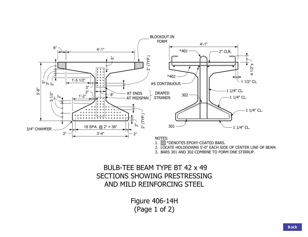
BARS 301 AND 302 COMBINE TO FORM ONE STIRRUP.3.
LOCATE HOLDDOWNS 5’-0" EACH SIDE OF CENTER LINE OF BEAM.2.
*DENOTES EPOXY-COATED BARS.1.
NOTES:
FORM
BLOCKOUT IN
3’-4"
3’-6"
6"4’-1"
2"
4’-1"
(Page 1 of 2)
Figure 406-14H
AND MILD REINFORCING STEEL
SECTIONS SHOWING PRESTRESSING
BULB-TEE BEAM TYPE BT 42 x 49
*401
AT ENDS
AT MIDSPAN STRANDS
DRAPED
2"
7"
5 1/2"
3"3"5"
5"
8"
4 1/2"–
2" CLR.
1 1/2" CL.
1 1/4" CL.
1 1/4" CL.
1 1/4" CL.
1 1/4" CL.
2" (T
YP.)
2" (T
YP.)
3/4" CHAMFER
1’-5 1/2"
3"
2"
1’-2"
2"
18 SPA. @ 2" = 36"
2"

63°
*402
7"
*401
301
*401
* DENOTES EPOXY-COATED BARS
302
1’-0"
27°
5 1/2"
BULB-TEE BEAM TYPE BT 42 x 49
BAR BENDING DETAILS
Figure 406-14H
(Page 2 of 2)
END VIEW SIDE VIEW
3’-1"
1’-6"
3’-6"
3 1/2"
8 3/4"
4 1/2"
5 1/2"
3’-10"

BARS 301 AND 302 COMBINE TO FORM ONE STIRRUP.3.
LOCATE HOLDDOWNS 5’-0" EACH SIDE OF CENTER LINE OF BEAM.2.
*DENOTES EPOXY-COATED BARS.1.
NOTES:
5"
(Page 1 of 2)
Figure 406-14 I
AND MILD REINFORCING STEEL
SECTIONS SHOWING PRESTRESSING
BULB-TEE BEAM TYPE BT 48 x 49
FORM
BLOCKOUT IN
4 1/2
"–
4’-1"
4’-1"6"
4’-0"
8"
2"
3’-4"
3/4" CHAMFER
2"
7"
5 1/2
"3"3"5"
#6 CONTINUOUS
*402
*401 2" CL.
1 1/4" CL.
1 1/4" CL.
1 1/4" CL.
1 1/4" CL.
1 1/2" CL.
AT ENDS
AT MIDSPAN STRANDS
DRAPED
2" (T
YP.)
2" (T
YP.)
301
302
2"
18 SPA. @ 2" = 36"
2"
2"
1’-2"
1’-5 1/2"
3"

*402
*401
301
3’-1"
1’-6"
*401
* DENOTES EPOXY-COATED BARS
END VIEW SIDE VIEW
5 1/2"
3’-10"
4’-0"
3 1/2"
7"
4 1/2"
8 3/4"
302
1’-0"
27°
5 1/2"
63°
BULB-TEE BEAM TYPE BT 48 x 49
BAR BENDING DETAILS
Figure 406-14 I
(Page 2 of 2)

BARS 301 AND 302 COMBINE TO FORM ONE STIRRUP.3.
LOCATE HOLDDOWNS 5’-0" EACH SIDE OF CENTER LINE OF BEAM.2.
*DENOTES EPOXY-COATED BARS.1.
NOTES:
(Page 1 of 2)
Figure 406-14J
AND MILD REINFORCING STEEL
SECTIONS SHOWING PRESTRESSING
BULB-TEE BEAM TYPE BT 54 x 49
#6 CONTINUOUS
*402
301
STRANDS
DRAPED
*401 2" CL.
4 1/2
"–
4’-1"
2"
3’-4"
4’-6"
6"
5"
4’-1"
8"AT ENDS
AT MIDSPAN
3"
3"
5"
3/4" CHAMFER
2" (T
YP.)
2" (T
YP.)
1 1/2" CL.
1 1/4" CL.
1 1/4" CL.
1 1/4" CL.
1 1/4" CL.
302
IN FORM
BLOCKOUT
2"
7"
5 1/2
"
2"
18 SPA. @ 2" = 36"
2"
2"
1’-2"
1’-5 1/2" 3"

*402
*401
301
3’-1"
*401
302
1’-0"
27°
5 1/2"
END VIEW SIDE VIEW
BULB-TEE BEAM TYPE BT 54 x 49
BAR BENDING DETAILS
Figure 406-14J
(Page 2 of 2)
63°
8 3/4"
4 1/2"
4’-6"
3’-10"
7"
3 1/2"
1’-6"
5 1/2"
* DENOTES EPOXY-COATED BARS

BARS 301 AND 302 COMBINE TO FORM ONE STIRRUP.3.
LOCATE HOLDDOWNS 5’-0" EACH SIDE OF CENTER LINE OF BEAM.2.
*DENOTES EPOXY-COATED BARS.1.
NOTES:
5"
(Page 1 of 2)
Figure 406-14K
AND MILD REINFORCING STEEL
SECTIONS SHOWING PRESTRESSING
BULB-TEE BEAM TYPE BT 60 x 49
IN FORM
BLOCKOUT
302
4 1/2
"–
1 1/2" CL.
4’-1"
*401 2" CL.
*402
#6 CONTINUOUS
301
1 1/4" CL.
1 1/4" CL.
1 1/4" CL.
1 1/4" CL.
4’-1"6"
8"
5’-0"
3’-4"
2"
STRANDS
DRAPED AT ENDS
AT MIDSPAN
3/4" CHAMFER
2"
7"
5 1/2
"3"
3"
5"
2"
2" (T
YP.)
2" (T
YP.)
2"
18 SPA. @ 2" = 36"
2"
1’-2"
1’-5 1/2" 3"

*402
*401
301
3’-1"
*401
* DENOTES EPOXY-COATED BARS
5’-0"
4 1/2"
3’-10"
5 1/2"
7"
3 1/2"
1’-6"
63°
8 3/4"
END VIEW SIDE VIEW
302
1’-0"
27°
5 1/2"
BULB-TEE BEAM TYPE BT 60 x 49
BAR BENDING DETAILS
Figure 406-14K
(Page 2 of 2)
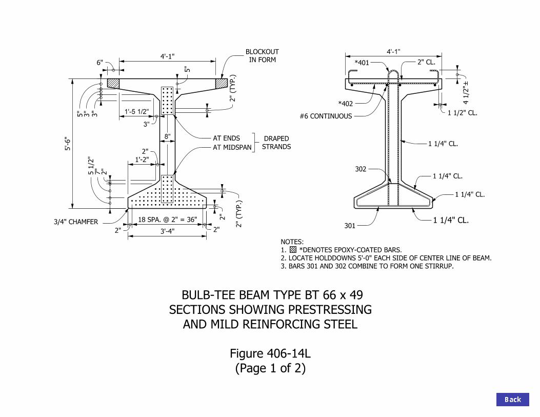
2" CL.
302
IN FORM
BLOCKOUT
1 1/4" CL.
BARS 301 AND 302 COMBINE TO FORM ONE STIRRUP.3.
LOCATE HOLDDOWNS 5’-0" EACH SIDE OF CENTER LINE OF BEAM.2.
*DENOTES EPOXY-COATED BARS.1.
NOTES:
8"
4’-1"
(Page 1 of 2)
Figure 406-14L
AND MILD REINFORCING STEEL
SECTIONS SHOWING PRESTRESSING
BULB-TEE BEAM TYPE BT 66 x 49
AT ENDS
AT MIDSPAN
301
*402
*401
#6 CONTINUOUS
STRANDS
DRAPED
6"4’-1"
5"
5’-6"
3’-4"
2"
2"
7"
5 1/2
"3"
3"
5"
3/4" CHAMFER
2" (T
YP.)
2" (T
YP.)
1 1/2" CL.
4 1/2
"–
1 1/4" CL.
1 1/4" CL.
1 1/4" CL.
1’-5 1/2"
3"
2"
1’-2"
2"
18 SPA. @ 2" = 36"
2"

63°
*402
3’-10"
*401
301
3’-1"
1’-6"
*401
* DENOTES EPOXY-COATED BARS
BULB-TEE BEAM TYPE BT 66 x 49
BAR BENDING DETAILS
Figure 406-14L
(Page 2 of 2)
SIDE VIEWEND VIEW
4 1/2"
8 3/4"
7"
3 1/2"
5 1/2"
302
1’-0"
27°
5 1/2"
5’-6"

3" 7"
2’-1"
5’-0"
2’-5"2"
5’-0"
1’-11"3"
5"
1’-11"3"
4’-6"
8"
2’-2"
9"
8"
4"
4"
3"
9"5"
2 EQ. SPA.
1"
2"
2"
= 1’-2"7 @ 2"
BEAM PROPERTIES
B
B
TB
BB
3
3
BB
TB
2
S = 15,590 IN.
S = 12,025 IN.
Y = 23.5 IN.
Y = 30.5 IN.
WT. = 973 LB/LF
1’-11 1/2 "
3 1/2 " =1’-6"9 @ 2"
3 1/2 "
301
302
*401
*402
# 6
1" CL.
1" CL.
403
1 1/4 " CL.
1" CL.
1 1/4 " C
L.
2A = 934 IN.
I = 366,592 IN. *DENOTES EPOXY-COATED BARS2.
BARS 301 AND 302 COMBINED TO FORM ONE STIRRUP.1.
NOTES:
(Page 1 of 2)
Figure 406-14M
BULB-TEE BEAM TYPE BT 54 x 60

*402
301
*401 *401
45°
1’-11"
4’-10"
7"
* DENOTES EPOXY-COATED BARS
7"
302
45°7
1/2 "
BULB-TEE BEAM TYPE BT 54 x 60BAR BENDING DETAILS
Figure 406-14M(Page 2 of 2)
SIDE VIEWEND VIEW
10 1/4"
6 1/4"
4 1/2"
2 1/2"
3 1/2"
403
5’-11"
3 1/2"
2 1/2"
5 1/2"
4’-7"

3" 7"
2’-1"
5’-0"
2’-5"2"
5’-0"
1’-11"3"
5"
1’-11"3"
5’-0"
8"
1 1/4 " cl.
1" cl.
301
302
*401
*402
# 6
2’-8"
9"
8"
4"
4"
3"
9"
5"
2 EQ. SPA.
1"
2"
2"
= 1’-2"7 @ 2"
1 1/4 " cl.
1" cl.
1" cl.
BEAM PROPERTIES
B2
B
TB
BB
3
3
BB
TB
A = 976 in
I = 478,833 in2
S = 18,180 in
S = 14,223 in
Y = 26.3 in
Y = 33.7 in
1’-11 1/2 "
3 1/2 "=1’-6"9 @ 2"
3 1/2 "
403
2. *DENOTES EPOXY-COATED BARS
TO FORM ONE STIRRUP.
1. BARS 301 AND 302 COMBINED
NOTES:
Wt. = 1017 lb/lf
60 x 60
(Page 1 of 2)
Figure 406-14N
TYPE BT
BULB - TEE BEAM

301
302
45°
45°
1’-11"
6 1/4 "
10 1/4 "
7 1/2 "
2 1/2 "
* DENOTES EPOXY-COATED BARS
*402
SIDE VIEW
*401 *401402
4’-10"
7"
END VIEW3 1/2 "
5’-11"
5 1/2 "
2 1/2 "
5’-1"
7"
3 1/2 "
4 1/2 "
BULB - TEE BEAMTYPE BT 60 x 60
BAR BENDING DETAILS
Figure 406-14N(Page 2 of 2)

3" 7"
2’-1"
2’-5"2"
1’-11"3"
5"
1’-11"3"
5’-6"
8"
1 1/4 " cl.
1" cl.
301
302
*401
*402
# 6
3’-2"
9"
8"
4"
4"
3"
9"
5"
2 EQ. SPA.
1"
2"
2"
= 1’-2"7 @ 2"
1 1/4 " cl.
1" cl.
1" cl.
BEAM PROPERTIES
B2
B
TB
BB
3
3
BB
TB
I = 608,591 in4
S = 20,859 in
S = 16,527 in
Y = 29.2 in
Y = 36.8 in
1’-11 1/2 "
3 1/2 "=1’-6"9 @ 2"
3 1/2 "
A = 1018 in
5’-0"
403
2. *DENOTES EPOXY-COATED BARS
TO FORM ONE STIRRUP.
1. BARS 301 AND 302 COMBINED
NOTES:
Wt. = 1060 lb/lf
5’-0"
66 x 60
(Page 1 of 2)
Figure 406-14 O
TYPE BT
BULB - TEE BEAM

301
302
45°
45°
1’-11"
6 1/4 "
10 1/4 "
7 1/2 "
2 1/2 "
* DENOTES EPOXY-COATED BARS
*402
SIDE VIEW
*401 *401402
4’-10"
7"
END VIEW3 1/2 "
5’-11"
5 1/2 "
2 1/2 "
5’-7"
7"
3 1/2 "
4 1/2 "
BULB - TEE BEAMTYPE BT 66 x 60
BAR BENDING DETAILS
Figure 406-14 O(Page 2 of 2)

3" 7"
2’-1"
5’-0"
2’-5"2"
5’-0"
1’-11"3"
5"
1’-11" 3"
6’-0"
8"
1 1/4 " cl.
1" cl.
302
*401
*402
# 6
3’-8"
9"
8"
4"
4"
3"
9"
5"
2 EQ. SPA.
1"
2"
2"
= 1’-2"7 @ 2"
1 1/4 " cl.
1" cl.
1" cl.
BEAM PROPERTIES
B2
B
TB
BB
3
3
BB
TB
I = 756,629 in2
S = 23,625 in
S = 18,929 in
Y = 32.0 in
Y = 40.0 in
A = 1060 in
1’-11 1/2 "
=1’-6"9 @ 2"
3 1/2 "3 1/2 "
301
403
2. *DENOTES EPOXY-COATED BARS
TO FORM ONE STIRRUP.
1. BARS 301 AND 302 COMBINED
NOTES:
Wt. = 1104 lb/lf
72 x 60
(Page 1 of 2)
Figure 406-14P
TYPE BT
BULB - TEE BEAM

301
302
45°
45°
1’-11"
6 1/4 "
10 1/4 "
7 1/2 "
2 1/2 "
* DENOTES EPOXY-COATED BARS
*402
SIDE VIEW
*401 *401402
4’-10"
7"
END VIEW3 1/2 "
5’-11"
5 1/2 "
2 1/2 "
6’-1"
7"
3 1/2 "
4 1/2 "
BULB - TEE BEAMTYPE BT 72 x 60
BAR BENDING DETAILS
Figure 406-14P(Page 2 of 2)

3"
2’-1"
5’-0"
2"
5’-0"
1’-11"3"
5"
1’-11"3"
6’-6"
8"
1 1/4 " cl.
1" cl.
301
302
*401
# 6
4’-2"
9"
8"
4"
4"
3"
9"
5"
2 EQ. SPA.
1"
2"
1 1/4 " cl.
1" cl.
1" cl.
BEAM PROPERTIES
B2
B
TB
BB
3
3
BB
TB
I = 923,707 in2
S = 26,475 in
S = 21,426 in
Y = 34.9 in
Y = 43.1 in
A = 1102 in
1’-11 1/2 "
2’-5"
3 1/2 " =1’-6"9 @ 2"
3 1/2 "
= 1’-2"7 @ 2"
2"
7"
403
2. *DENOTES EPOXY-COATED BARS
TO FORM ONE STIRRUP.
1. BARS 301 AND 302 COMBINED
NOTES:
*402
Wt. = 1148 lb/lf
78 x 60
(Page 1 of 2)
Figure 406-14Q
TYPE BT
BULB - TEE BEAM

301
302
45°
45°
1’-11"
6 1/4 "
10 1/4 "
7 1/2 "
2 1/2 "
* DENOTES EPOXY-COATED BARS
*402
SIDE VIEW
*401 *401402
4’-10"
7"
END VIEW3 1/2 "
5’-11"
5 1/2 "
2 1/2 "
6’-7"
7"
3 1/2 "
4 1/2 "
BULB - TEE BEAMTYPE BT 78 x 60
BAR BENDING DETAILS
Figure 406-14Q(Page 2 of 2)

3"
2’-1"
5’-0"
2"
5’-0"
1’-11"3"
5"
1’-11"3"
7’-0"
8"
1 1/4 " cl.
1" cl.
301
302
*401
*402
# 6
4’-8"
9"
8"
4"
4"
3"
9"
5"
2 EQ. SPA.
1"
2"
1 1/4 " cl.
1" cl.
1" cl.
BEAM PROPERTIES
B2
B
TB
BB
3
3
BB
TB
2
S = 29,410 in
S = 24,019 in
Y = 37.8 in
Y = 46.2 in
A = 1144 in
1’-11 1/2 "
2’-5"
3 1/2 " =1’-6"9 @ 2"
3 1/2 "
= 1’-2"7 @ 2"
2"
7"
I = 1,110,587 in
403
2. *DENOTES EPOXY-COATED BARS
TO FORM ONE STIRRUP.
1. BARS 301 AND 302 COMBINED
NOTES:
Wt. = 1192 lb/lf
84 x 60
(Page 1 of 2)
Figure 406-14R
TYPE BT
BULB - TEE BEAM

301
302
45°
45°
1’-11"
6 1/4 "
10 1/4 "
7 1/2 "
2 1/2 "
* DENOTES EPOXY-COATED BARS
*402
SIDE VIEW
*401 *401402
4’-10"
7"
END VIEW3 1/2 "
5’-11"
5 1/2 "
2 1/2 "
7’-1"
7"
3 1/2 "
4 1/2 "
BULB - TEE BEAMTYPE BT 84 x 60
BAR BENDING DETAILS
Figure 406-14R(page 2 of 2)

BARS 301 AND 302 COMBINE TO FORM ONE STIRRUP.3.
LOCATE HOLDDOWNS 5’-0" EACH SIDE OF CENTER LINE OF BEAM.2.
*DENOTES EPOXY-COATED BARS.1.
NOTES:
3/4" CHAMFER
3’-4"
2"
1’-2"
3’-0"
8"
5’-1"
5"
2"
(Page 1 of 2)
Figure 406-14S
AND MILD REINFORCING STEEL
SECTIONS SHOWING PRESTRESSING
WIDE BULB-TEE BEAM TYPE BT 36 x 61
AT ENDS
AT MIDSPAN STRANDS
DRAPED
301
#6 CONTINUOUS
*402
*401
5’-1"
4 1/2
"–
2" CL.
1 1/2" CL.1 1/4" CL.
1 1/4" CL.
1 1/4" CL.
1 1/4" CL.2" (T
YP.)
1’-11 1/2"
3"
2"
7"
5 1/2
"
302
3"
4"
4"
2" (T
YP.)
2"
18 SPA. @ 2" = 36"
2"

*402
4’-10"
7"
*401
3’-0"
301
3’-1"
1’-6"
*401
* DENOTES EPOXY-COATED BARS
302
1’-0"
27°
5 1/2"
WIDE BULB-TEE BEAM TYPE BT 36 x 61
BAR BENDING DETAILS
Figure 406-14S
(Page 2 of 2)
END VIEW SIDE VIEW
63°
3 1/2"
4 1/2"
8 3/4"
5 1/2"

BARS 301 AND 302 COMBINE TO FORM ONE STIRRUP.3.
LOCATE HOLDDOWNS 5’-0" EACH SIDE OF CENTER LINE OF BEAM.2.
*DENOTES EPOXY-COATED BARS.1.
NOTES:
3’-4"
8"
5’-1"
5"
3"
4"
4"
(Page 1 of 2)
Figure 406-14T
AND MILD REINFORCING STEEL
SECTIONS SHOWING PRESTRESSING
WIDE BULB-TEE BEAM TYPE BT 42 x 61
4 1/2"–
5’-1"3’-6"
2"
2"
7"
5 1/2"
AT ENDS
AT MIDSPAN
*401
*402
STRANDS
DRAPED
2" (T
YP.)
2" (T
YP.)
3/4" CHAMFER
#6 CONTINUOUS
301
302
2" CL.
1 1/2" CL.
1 1/4" CL.
1 1/4" CL.
1 1/4" CL.
1 1/4" CL.
2"1’-2"
1’-11 1/2"
3"
2"
18 SPA. @ 2" = 36"
2"

*402
4’-10"
7"
*401
3’-6"
301
3’-1"
1’-6"
*401
* DENOTES EPOXY-COATED BARS
WIDE BULB-TEE BEAM TYPE BT 42 x 61
BAR BENDING DETAILS
Figure 406-14T
(Page 2 of 2)
SIDE VIEWEND VIEW
302
1’-0"
27°
5 1/2"
63°
3 1/2"
5 1/2"
4 1/2"
8 3/4"

BARS 301 AND 302 COMBINE TO FORM ONE STIRRUP.3.
LOCATE HOLDDOWNS 5’-0" EACH SIDE OF CENTER LINE OF BEAM.2.
*DENOTES EPOXY-COATED BARS.1.
NOTES:
3’-4"
4’-0"
8"
5’-1"
5"
2"
5’-1"
3"
4"
4"
(Page 1 of 2)
Figure 406-14U
AND MILD REINFORCING STEEL
SECTIONS SHOWING PRESTRESSING
WIDE BULB-TEE BEAM TYPE BT 48 x 61
AT ENDS
AT MIDSPAN
#6 CONTINUOUS
301
*402
*401
STRANDS
DRAPED
3021 1/4" CL.
1 1/4" CL.
1 1/4" CL.
1 1/4" CL.
1 1/2" CL.
4 1/2"–
2" CL.
2"
7"
5 1/2"
3/4" CHAMFER
2" (T
YP.)
2" (T
YP.)
1’-11 1/2"
3"
2"
18 SPA. @ 2" = 36"
2"
2"
1’-2"

*402
4’-10"
7"
*401
4’-0"
301
3’-1"
1’-6"
*401
* DENOTES EPOXY-COATED BARS
302
1’-0"
27°
5 1/2"
END VIEW SIDE VIEW
WIDE BULB-TEE BEAM TYPE BT 48 x 61
BAR BENDING DETAILS
Figure 406-14U
(Page 2 of 2)
3 1/2"
8 3/4"
4 1/2"
5 1/2"
63°

BARS 301 AND 302 COMBINE TO FORM ONE STIRRUP.3.
LOCATE HOLDDOWNS 5’-0" EACH SIDE OF CENTER LINE OF BEAM.2.
*DENOTES EPOXY-COATED BARS.1.
NOTES:
3’-4"
4’-6" 8"
5’-1"
5"
2"
5’-1"
3"4"
4"
(Page 1 of 2)
Figure 406-14V
AND MILD REINFORCING STEEL
SECTIONS SHOWING PRESTRESSING
WIDE BULB-TEE BEAM TYPE BT 54 x 61
AT ENDS
AT MIDSPAN
301
*402
*401
#6
1/2" Ø STRAND
2"
7"
5 1/2" STRANDS
DRAPED
2" (T
YP.)
2" (T
YP.)
3/4" CHAMFER
2" CL.
1 1/2" CL.
1 1/4" CL.
1 1/4" CL.
1 1/4" CL.
1 1/4" CL.
302
1’-11 1/2"
3"
5"
2"
18 SPA. @ 2" = 36"
2"
2"
1’-2"

*402
4’-10"
7"
*401
4’-7"
301
3’-1"
1’-6"
*401
* DENOTES EPOXY-COATED BARS
WIDE BULB-TEE BEAM TYPE BT 54 x 61
BAR BENDING DETAILS
Figure 406-14V
(Page 2 of 2)
4 1/2"
8 3/4"
5 1/2"
END VIEW SIDE VIEW
302
1’-0"
27°
5 1/2"
63°
3 1/2"

BARS 301 AND 302 COMBINE TO FORM ONE STIRRUP.3.
LOCATE HOLDDOWNS 5’-0" EACH SIDE OF CENTER LINE OF BEAM.2.
*DENOTES EPOXY-COATED BARS.1.
NOTES:
3’-4"
5’-0"
8"
5’-1"
5"
2"
5’-1"
3"4"
4"
(Page 1 of 2)
Figure 406-14W
AND MILD REINFORCING STEEL
SECTIONS SHOWING PRESTRESSING
WIDE BULB-TEE BEAM TYPE BT 60 x 61
AT ENDS
AT MIDSPAN
#6 CONTINUOUS
*401
*402
301
STRANDS
DRAPED
3/4" CHAMFER
2" (T
YP.)
2" (T
YP.)
2" CL.
1 1/4" CL.
1 1/4" CL.
1 1/4" CL.
1 1/4" CL.
1 1/2" CL.
3022"
7"
5 1/2
"
4 1/2
"–
2"
18 SPA. @ 2" = 36"
2"
2"
1’-2"
1’-11 1/2"
3"

*402
4’-10"
7"
*401
5’-0"
301
3’-1"
1’-6"
*401
* DENOTES EPOXY-COATED BARS
302
1’-0"
27°
5 1/2"
END VIEW SIDE VIEW
WIDE BULB-TEE BEAM TYPE BT 60 x 61
BAR BENDING DETAILS
Figure 406-14W
(Page 2 of 2)
4 1/2"
8 3/4"
3 1/2"
5 1/2"
63°

BARS 301 AND 302 COMBINE TO FORM ONE STIRRUP.3.
LOCATE HOLDDOWNS 5’-0" EACH SIDE OF CENTER LINE OF BEAM.2.
*DENOTES EPOXY-COATED BARS.1.
NOTES:
3’-4"
5’-6" 8"
5’-1"
5"
2"
5’-1"
3"4"
4"
(Page 1 of 2)
Figure 406-14X
AND MILD REINFORCING STEEL
SECTIONS SHOWING PRESTRESSING
WIDE BULB-TEE BEAM TYPE BT 66 x 61
AT ENDS
AT MIDSPAN
#6 CONTINUOUS
*402
*401
STRANDS
DRAPED
3/4" CHAMFER
2" (T
YP.)
2" (T
YP.)
1 1/2" CL.
2" CL.
301
302
1 1/4" CL.
1 1/4" CL.
1 1/4" CL.
1 1/4" CL.
2"
7"
5 1/2
"
4 1/2
"–
2"
18 SPA. @ 2" = 36"
2"
2"
1’-2"
1’-11 1/2"
3"

*402
4’-10"
7"
*401
301
3’-1"
1’-6"
*401
* DENOTES EPOXY-COATED BARS
302
1’-0"
27°
5 1/2"
5’-6"
63°
3 1/2"
4 1/2"
8 3/4"
5 1/2"
SIDE VIEWEND VIEW
WIDE BULB-TEE BEAM TYPE BT 66 x 61
BAR BENDING DETAILS
Figure 406-14X
(Page 2 of 2)

END BENT
OR PIER
INTERIOR BENT
301
1’-10"1’-10"
2"
SHOP BEND AS SHOWN. DO NOT HEAT.
ROW WITH 1’-10" PROJECTION AND
CUT BONDED STRANDS IN BOTTOM
*401
(1 e.f.)
2 - #6
6"3"2"
4 1/2 "4 1/2 "
(1 e.f.)
2 - #6 x 2’-9"
(2 e.f.)
4 - #6 x 1’-9"
1’-5 1/2 "
1’-5 1/2 "
(2 e.f.)
4 - #6 x 2’-9"
*402
DENOTES EPOXY-COATED BARS*2.
1. THE 302 AND 403 BARS REQUIRED IN SOME SECTIONS ARE NOT SHOWN.
NOTES:
BULB - TEE BEAM (36 DEPTH)
ELEVATIONS SHOWING END REINFORCEMENT
Figure 406-14Y
(Page 1 of 9)

END BENT
OR PIER
INTERIOR BENT
1’-10"1’-10"
2"
6"3"2"
4 1/2 "4 1/2 "
1’-5 1/2 "
1’-5 1/2 "
DENOTES EPOXY-COATED BARS*2.
1. THE 302 AND 403 BARS REQUIRED IN SOME SECTIONS ARE NOT SHOWN.
NOTES:
301
SHOP BEND AS SHOWN. DO NOT HEAT.
ROW WITH 1’-10" PROJECTION AND
CUT BONDED STRANDS IN BOTTOM
*401
(1 e.f.)
2 - #6
(1 e.f.)
2 - #6 x 3’-3"
(2 e.f.)
4 - #6 x 2’-3"
(2 e.f.)
4 - #6 x 3’-3"
*402
BULB - TEE BEAM (42 DEPTH)
ELEVATIONS SHOWING END REINFORCEMENT
Figure 406-14Y
(Page 2 of 9)

END BENT OR PIER
INTERIOR BENT
1’-10"1’-10"
2"
6"3"2"
4 1/2 "4 1/2 "
1’-5 1/2 "
1’-5 1/2 "
DENOTES EPOXY-COATED BARS*2.
1. THE 302 AND 403 BARS REQUIRED IN SOME SECTIONS ARE NOT SHOWN.
NOTES:
301
*401
(1 e.f.)
2 - #6
(1 e.f.)
2 - #6 x 3’-9"
(2 e.f.)
4 - #6 x 2’-9"
(2 e.f.)
4 - #6 x 3’-9"
*402
AS SHOWN. DO NOT HEAT. (TYP. EA. END)
WITH 1’-10" PROJECTION AND SHOP BEND
CUT BONDED STRANDS IN BOTTOM ROW
BULB - TEE BEAM (48 DEPTH)
ELEVATIONS SHOWING END REINFORCEMENT
Figure 406-14Y
(Page 3 of 9)

END BENT
OR PIER
INTERIOR BENT
1’-10"1’-10"
2"
6"3"2"
4 1/2 "4 1/2 "
1’-5 1/2 "
1’-5 1/2 "
DENOTES EPOXY-COATED BARS*2.
1. THE 302 AND 403 BARS REQUIRED IN SOME SECTIONS ARE NOT SHOWN.
NOTES:
301
SHOP BEND AS SHOWN. DO NOT HEAT.
ROW WITH 1’-10" PROJECTION AND
CUT BONDED STRANDS IN BOTTOM
*401
(1 e.f.)
2 - #6
(1 e.f.)
2 - #6 x 4’-3"
(2 e.f.)
4 - #6 x 3’-4"
(2 e.f.)
4 - #6 x 4’-3"
*402
BULB - TEE BEAM (54 DEPTH)
ELEVATIONS SHOWING END REINFORCEMENT
Figure 406-14Y
(Page 4 of 9)

END BENT
OR PIER
INTERIOR BENT
1’-10"1’-10"
2"6"
3"2"
4 1/2 "4 1/2 "
1’-5 1/2 "
1’-5 1/2 "
DENOTES EPOXY-COATED BARS*2.
1. THE 302 AND 403 BARS REQUIRED IN SOME SECTIONS ARE NOT SHOWN.
NOTES:
301
SHOP BEND AS SHOWN. DO NOT HEAT.
ROW WITH 1’-10" PROJECTION AND
CUT BONDED STRANDS IN BOTTOM
*401
(1 e.f.)
2 - #6
(1 e.f.)
2 - #6 x 4’-9"
(2 e.f.)
4 - #6 x 3’-10" (2 e.f.)
4 - #6 x 4’-9"
*402
BULB - TEE BEAM (60 DEPTH)
ELEVATIONS SHOWING END REINFORCEMENT
Figure 406-14Y
(Page 5 of 9)

END BENT OR PIER
INTERIOR BENT
1’-10"1’-10"
2"6"
3"2"
4 1/2 "4 1/2 "
1’-5 1/2 "
1’-5 1/2 "
DENOTES EPOXY-COATED BARS*2.
1. THE 302 AND 403 BARS REQUIRED IN SOME SECTIONS ARE NOT SHOWN.
NOTES:
301
SHOP BEND AS SHOWN. DO NOT HEAT.
ROW WITH 1’-10" PROJECTION AND
CUT BONDED STRANDS IN BOTTOM
*401
(1 e.f.)
2 - #6
(1 e.f.)
2 - #6 x 5’-3"
(2 e.f.)
4 - #6 x 4’-4" (2 e.f.)
4 - #6 x 5’-3"
*402
BULB - TEE BEAM (66 DEPTH)
ELEVATIONS SHOWING END REINFORCEMENT
Figure 406-14Y
(Page 6 of 9)

END BENT
OR PIER
INTERIOR BENT
1’-10"
2"6"
3"2"
4 1/2 "4 1/2 "
1’-5 1/2 "
1’-5 1/2 "
1’-10"
BARS
DENOTES EPOXY-COATED*2.
SHOWN.
SECTIONS ARE NOT
REQUIRED IN SOME
1. THE 302 AND 403 BARS
NOTES:301
SHOP BEND AS SHOWN. DO NOT HEAT.
ROW WITH 1’-10" PROJECTION AND
CUT BONDED STRANDS IN BOTTOM
*401
(1 e.f.)
2 - #6
" STRAND21
(1 e.f.)
2 - #6 x 5’-9"
(2 e.f.)
4 - #6 x 4’-10"
(2 e.f.)
4 - #6 x 5’-9"
*402
BULB - TEE BEAM (72 DEPTH)
ELEVATIONS SHOWING END REINFORCEMENT
Figure 406-14Y
(Page 7 of 9)

END BENT
OR PIER
INTERIOR BENT
1’-10"1’-10"
2"
4 1/2 "4 1/2 "
1’-5 1/2 "
1’-5 1/2 "
DENOTES EPOXY-COATED BARS*2.
1. THE 302 AND 403 BARS REQUIRED IN SOME SECTIONS ARE NOT SHOWN.
NOTES:
6"3"
2"
301
SHOP BEND AS SHOWN. DO NOT HEAT.
ROW WITH 1’-10" PROJECTION AND
CUT BONDED STRANDS IN BOTTOM
*401
(1 e.f.)
2 - #6
(1 e.f.)
2 - #6 x 6’-3"
(2 e.f.)
4 - #6 x 5’-4"
(2 e.f.)
4 - #6 x 6’-3"
*402
BULB - TEE BEAM (78 DEPTH)
ELEVATIONS SHOWING END REINFORCEMENT
Figure 406-14Y
(Page 8 of 9)

END BENT OR PIER
INTERIOR BENT
1’-10"1’-10"
2"3"2"
4 1/2 "4 1/2 "
1’-5 1/2 "
1’-5 1/2 "
DENOTES EPOXY-COATED BARS*2.
1. THE 302 AND 403 BARS REQUIRED IN SOME SECTIONS ARE NOT SHOWN.
NOTES:
6"
301
SHOP BEND AS SHOWN. DO NOT HEAT.
ROW WITH 1’-10" PROJECTION AND
CUT BONDED STRANDS IN BOTTOM
*401
(1 e.f.)
2 - #6
(1 e.f.)
2 - #6 x 6’-9"
(2 e.f.)
4 - #6 x 5’-10"
(2 e.f.)
4 - #6 x 6’-9"
*402
BULB - TEE BEAM (84 DEPTH)
ELEVATIONS SHOWING END REINFORCEMENT
Figure 406-14Y
(Page 9 of 9)

BULB - TEE BEAM
SECTION AT END SHOWING DRAPED STRANDS
Figure 406-14Z
=1’-2"7 @ 2"
2"
3"
Varies
3"
2"
3"
Varies
3"
=1’-0"6 @ 2"
2"
3 1/2 " =6"3 @ 2"
6" =6"3 @ 2"3 1/2 "

6"
2’-8"
2’-8"
1’-1"
402 x 3’-8"
3’-0"
3/8 "
1’-0"
3/4 "
4" 4"14 @ 2" = 2’-4"
Strand1/2" Ø
*401
cl.
1 1/4 "
1" Chamfer
6 - #5
2" cl.
402
2 1/4 "
3"
4"
4"
2"
2"
3/4" Chamfer
1/4" Chamfer
1 1/4 " cl.
B2
B
TB
BB
TB
BB
4
3
3
A = 423 in
Wt. = 441 lbs/ft
BEAM PROPERTIES
*401 x 5’-10"
1. *DENOTES EPOXY-COATED BAR
NOTES:
Figure 406-15A
TYPE CB 12 x 36
BOX BEAM
3"5 Spa. @ 6" = 2’-6"3"
I = 5,124 in
S = 850 in
S = 858 in
Y = 6.03 in
Y = 5.97 in

402 x 3’-8"
B2
B
TB
BB
TB
BB
4
3
3
BEAM PROPERTIES
A = 471 in
I = 14,169 in
S = 1,653 in
S = 1,681 in
Y = 8.57 in
Y = 8.43 in
Wt. = 491 lbs/ft
5 1/2 "2’-1"5 1/2 "
3"
3"6"
5 1/2 "
*401 x 6’-8"
6"
2’-8"
2’-8"
1’-6"
3’-0"
3/8 "
1’-5"
3/4 "
4" 4"14 @ 2" = 2’-4"
Strand1/2" Ø
*401
cl.
1 1/4 "
1" Chamfer
6 - #5
402
2 1/4 "
3/4" Chamfer
1/4" Chamfer
1 1/4 " cl.
Figure 406-15B
TYPE CB 17 x 36
BOX BEAM
cl.
1"
1. *DENOTES EPOXY-COATED BAR
NOTES:
2 @ 2" = 4"
2"
8"
4"
4"
3"5 Spa. @ 6" = 2’-6"3"

402 x 3’-8"
B2
B
TB
BB
TB
BB
4
3
3
BEAM PROPERTIES
A = 515 in
I = 27,619 in
S = 2,417 in
S = 2,463 in
Y = 10.60 in
Y = 10.40 in
Wt. = 536 lbs/ft
5 1/2 "2’-1"5 1/2 "
3"
10"
5 1/2 "
*401 x 7’-4"
6"
2’-8"
2’-8"
1’-10"
3’-0"
3/8 "
3/4 "
4" 4"14 @ 2" = 2’-4"
Strand1/2" Ø
*401
cl.
1 1/4 "
1" Chamfer
6 - #5
402
3/4" Chamfer
1 1/4 " cl.
3"
1’-9"
2 1/4 "
cl.
1"
3"5 Spa. @ 6" = 2’-6"3"
1’-0"
4"
4"
2 @ 2" = 4"
2"
Figure 406-15C
TYPE CB 21 x 36
BOX BEAM
1/4" Chamfer
1. *DENOTES EPOXY-COATED BAR
NOTES:
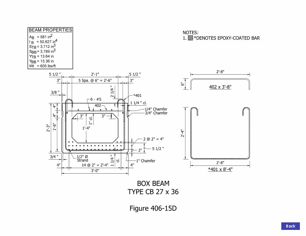
402 x 3’-8"
B2
B
TB
BB
TB
BB
4
3
3
BEAM PROPERTIES
A = 581 in
I = 50,627 in
S = 3,712 in
S = 3,789 in
Y = 13.64 in
Y = 13.36 in
Wt. = 605 lbs/ft
5 1/2 "2’-1"5 1/2 "
3"
1’-4"
5 1/2 "
*401 x 8’-4"
6"
2’-8"
2’-8"
2’-4"
3’-0"
3/8 "
3/4 "
4" 4"14 @ 2" = 2’-4"
Strand1/2" Ø
*401
cl.
1 1/4 "
1" Chamfer
6 - #5
402
2 1/4 "
3/4" Chamfer
1/4" Chamfer
1 1/4 " cl.
3"
2’-3"
Figure 406-15D
TYPE CB 27 x 36
BOX BEAM
1" cl.
1. *DENOTES EPOXY-COATED BAR
NOTES:
3"5 Spa. @ 6" = 2’-6"3"
1’-6"
4"
4"
2 @ 2" = 4"
2"

402 x 3’-8"
B2
B
TB
BB
TB
BB
4
3
3
BEAM PROPERTIES
A = 647 in
S = 5,168 in
S = 5,269 in
Y = 16.66 in
Y = 16.34 in
Wt. = 674 lbs/ft
5 1/2 "2’-1"5 1/2 "
3"
1’-10"
5 1/2 "
*401 x 9’-4"
6"
2’-8"
2’-8"
3’-0"
3/8 "
3/4 "
4" 4"14 @ 2" = 2’-4"
Strand1/2" Ø
*401
cl.
1 1/4 "
1" Chamfer
6 - #5
4022 1/4 "
3/4" Chamfer
1/4" Chamfer
1 1/4 " cl.
3"
2’-9"
1" cl.
Figure 406-15E
TYPE CB 33 x 36
BOX BEAM
1. *DENOTES EPOXY-COATED BAR
NOTES:
2’-10"
3"5 Spa. @ 6" = 2’-6"3"
2’-0"
4"
4"
2 @ 2" = 4"
2"
I = 86,092 in

402 x 3’-8"
B2
B
TB
BB
TB
BB
4
3
3
BEAM PROPERTIES
5 1/2 "2’-1"5 1/2 "
2’-7"
5 1/2 "
6"
2’-8"
2’-8"
3’-0"
3/8 "
3/4 "
4" 4"14 @ 2" = 2’-4"
Strand1/2" Ø
*401
cl.
1 1/4 "
1" Chamfer
6 - #5
4022 1/4 "
3/4" Chamfer
1/4" Chamfer
1 1/4 " cl.
3’-6"
1" cl.
A = 746 in
Wt. = 777 lbs/ft
2’-9"
4"
4"
3"
3"
Figure 406-15F
TYPE CB 42 x 36
BOX BEAM
*401 x 10’-10"
1. *DENOTES EPOXY-COATED BAR
NOTES:
3’-7"
3"3" 5 Spa. @ 6" = 2’-6"
2 @ 2" = 4"
2"
I = 161,496 in
S = 7,618 in
S = 7,764 in
Y = 21.20 in
Y = 20.80 in

6"
3’-8"
3’-8"
1’-1"
402 x 4’-8"
4’-0"
3/8 "
1’-0"
3/4 "
4" 4"
Strand1/2" Ø
*401
cl.
1 1/4 "
1" Chamfer
6 - #5
2" cl.
402
2 1/4 "
2"
2"
3/4" Chamfer
1/4" Chamfer
1 1/4 " cl.
B2
B
TB
BB
TB
BB
4
3
3
Y = 5.98 in
BEAM PROPERTIES
*401 x 6’-10"
1. *DENOTES EPOXY-COATED BAR
NOTES:
20 @ 2" = 3’-4"
Figure 406-15G
TYPE CB 12 x 48
BOX BEAM
A = 567 in
I = 6,852 in
S = 1,138 in
S = 1,146 in
Y = 6.02 in
Wt. = 591 lbs/ft
3"5 Eq. Spa. = 3’-6"3"
3"
4"
4"

402 x 4’-8"
B2
B
TB
BB
TB
BB
4
3
3
BEAM PROPERTIES
1. *DENOTES EPOXY-COATED BAR
NOTES:A = 603 in
I = 18,866 in
S = 2,204 in
S = 2,235 in
Y = 8.56 in
Wt. = 628 lbs/ft
Y = 8.44 in
3"3"6"
6"
3’-8"
3’-8"4’-0"
3/8 "
1’-5"
3/4 "
4" 4"
Strand1/2" Ø
*401
cl.
1 1/4 "
1" Chamfer
6 - #5
402
2 1/4 "
3/4" Chamfer
1/4" Chamfer
1 1/4 " cl.
20 @ 2" = 3’-4"
Figure 406-15H
TYPE CB 17 x 48
BOX BEAM
2 @ 2" = 4"
2"5 1/2 "
cl.
1"
5 1/2 "3’-1"5 1/2 "
*401 x 7’-8"
3"5 Eq. Spa. = 3’-6"3"
8"
4"
4"
1’-6"

402 x 4’-8"
B2
B
TB
BB
TB
BB
4
3
3
BEAM PROPERTIES
1. *DENOTES EPOXY-COATED BAR
NOTES:A = 647 in
I = 33,881 in
S = 3,202 in
S = 3,252 in
Y = 10.58 in
Wt. = 674 lbs/ft
Y = 10.42 in
3"
3"10"
6"
3’-8"
3’-8"
1’-10"
4’-0"
3/8 "
1’-9"
3/4 "
4" 4"
Strand1/2" Ø
*401
cl.
1 1/4 "
1" Chamfer
2 1/4 "
3/4" Chamfer
1/4" Chamfer
1 1/4 " cl.
20 @ 2" = 3’-4"
2 @ 2" = 4"
2"5 1/2 "
*401 x 8’-4"
cl.
1"
6 - #5
402
5 1/2 "3’-1"5 1/2 "
3"5 Eq. Spa. = 3’-6"3"
1’-0"
4"
4"
Figure 406-15 I
TYPE CB 21 x 48
BOX BEAM

402 x 4’-8"
B2
B
TB
BB
TB
BB
4
3
3
BEAM PROPERTIES
1. *DENOTES EPOXY-COATED BAR
NOTES:A = 713 in
I = 66,216 in
S = 4,865 in
S = 4,945 in
Y = 13.61 in
Wt. = 743 lbs/ft
Y = 13.39 in
3"
3"
1’-4"
6"
3’-8"
3’-8"
2’-4"
4’-0"
3/8 "
2’-3"
3/4 "
4" 4"
Strand1/2" Ø
*401
cl.
1 1/4 "
1" Chamfer
2 1/4 "
3/4" Chamfer
1/4" Chamfer
1 1/4 " cl.
20 @ 2" = 3’-4"
2 @ 2" = 4"
2"5 1/2 "
*401 x 9’-4"
cl.
1"
6 - #5
402
5 1/2 "3’-1"5 1/2 "
Figure 406-15J
TYPE CB 27 x 48
BOX BEAM
3"5 Eq. Spa. = 3’-6"3"
1’-6"
4"
4"

402 x 4’-8"
B2
B
TB
BB
TB
BB
4
3
3
BEAM PROPERTIES
1. *DENOTES EPOXY-COATED BAR
NOTES:
3"
3"
1’-10"
6"
3’-8"
3’-8"
2’-10"
4’-0"
3/8 "
2’-9"
3/4 "
4" 4"
Strand1/2" Ø
*401
cl.
1 1/4 "
1" Chamfer
2 1/4 "
3/4" Chamfer1/4" Chamfer
1 1/4 " cl.
20 @ 2" = 3’-4"
2 @ 2" = 4"
2"5 1/2 "
cl.
1"
6 - #5
402
2’-0"
4"
4"
3’-1"5 1/2 " 5 1/2 "
5 Eq. Spa. = 3’-6" 3"3"
Figure 406-15K
TYPE CB 33 x 48
BOX BEAM
A = 779 in
I = 111,384 in
S = 6,694 in
S = 6,808 in
Y = 16.64 in
Y = 16.36 in
Wt. = 811 lbs/ft
*401 x 10’-4"

402 x 4’-8"
B2
B
TB
BB
TB
BB
4
3
3
BEAM PROPERTIES
1. *DENOTES EPOXY-COATED BAR
NOTES:
3"
3"
2’-7"
6"
3’-8"
3’-8"
3’-7"
4’-0"
3/8 "
3’-6"
3/4 "
4" 4"
Strand1/2" Ø
*401
cl.
1 1/4 "
1" Chamfer
2 1/4 "
3/4" Chamfer1/4" Chamfer
1 1/4 " cl.
20 @ 2" = 3’-4"
2 @ 2" = 4"
2"5 1/2 "
cl.
1"
6 - #5
402
2’-9"
4"
4"
3’-1"5 1/2 " 5 1/2 "
5 Eq. Spa. = 3’-6" 3"3"
A = 878 in
I = 205,798 in
Y = 21.17 in
Y = 20.83 in
Wt. = 915 lbs/ft
*401 x 11’-10"
Figure 406-15L
TYPE CB 42 x 48
BOX BEAM
S = 9,721 in
S = 9,880 in

6"
3’-8"
3’-8"
10"
402 x 4’-8"
4’-0"
3/8 "
1’-0"
3/4 "
4" 4"
Strand1/2" Ø 401 c
l.
1"
1" Chamfer
5 - #5
402
2"
2"
3/4" Chamfer
1/4" Chamfer
B2
B
TB
BB
TB
BB
4
3
3
Y = 5.98 in
BEAM PROPERTIES
20 @ 2" = 3’-4"
A = 567 in
I = 6,852 in
S = 1,138 in
S = 1,146 in
Y = 6.02 in
Wt. = 591 lbs/ft
401 x 6’-4"
3"4 Eq. Spa. = 3’-6"3"
Figure 406-15M
TYPE WS 12 x 48
BOX BEAM
3"
4"
4"
1 1/4 " cl.2" cl.
cl.
1"

402 x 4’-8"
B2
B
TB
BB
TB
BB
4
3
3
BEAM PROPERTIES
A = 564 in
I = 18,467 in
S = 2,212 in
S = 2,135 in
Y = 8.35 in
Wt. = 588 lbs/ft
401 x 7’-2"
cl.
1"
4"1’-6 1/2 "3"1’-6 1/2 "4"
1 1/4 " cl.
6"
3’-8"
3’-8"
1’-3"
4’-0"
3/8 "
1’-5"
3/4 "
4" 4"
Strand1/2" Ø 401 c
l.
1"
1" Chamfer
5 - #5 402
3/4" Chamfer
1/4" Chamfer
3"4 Eq. Spa. = 3’-6"3"
8"
4"
4"
#4 x 3’-8"
Y = 8.65 in
Figure 406-15N
TYPE WS 17 x 48
BOX BEAM
cl.
1"
2"
2" 7"
4 1/2 "2"
20 @ 2" = 3’-4"

402 x 4’-8"
B2
B
TB
BB
TB
BB
4
3
3
BEAM PROPERTIES
A = 608 in
I = 32,826 in
S = 3,199 in
S = 3,056 in
Y = 10.26 in
Wt. = 633 lbs/ft
cl.
1"
4"1’-6 1/2 "3"1’-6 1/2 "4"
1 1/4 " cl.
6"
3’-8"
3’-8"
1’-7"
4’-0"
3/8 "
1’-9"
3/4 "
4" 4"
Strand1/2" Ø c
l.
1"
1" Chamfer
5 - #5 402
3/4" Chamfer
1/4" Chamfer
3"4 Eq. Spa. = 3’-6"3"
1’-0"
4"
4"
#4 x 3’-8"
Y = 10.74 in
2"
cl.
1"
11"
2"
2"
4 1/2 "
20 @ 2" = 3’-4"
401 x 7’-10"
401
Figure 406-15 O
TYPE WS 21 x 48
BOX BEAM

402 x 6’-2"
B2
B
TB
BB
TB
BB
4
3
3
BEAM PROPERTIES
A = 713 in
I = 66,216 in
S = 4,865 in
S = 4,945 in
Y = 13.61 in
Wt. = 743 lbs/ft
1 1/4 " cl.
4’-0"
3/8 "
2’-3"
3/4 "
4" 4"
Strand1/2" Ø 401 c
l.
1"
1" Chamfer
7 - #5 402
3/4" Chamfer
1/4" Chamfer
Y = 13.39 in
cl.
1"
3"
3"
5 1/2 "
1’-4"
3"6 Eq. Spa. = 3’-6"3"
cl.
1"
2 @ 2" = 4"
2"
20 @ 2" = 3’-4"
3’-8"
3"
1’-0"
10 1/2 " 1’-4" 10 1/2 "
3 1/2 "3 1/2 "
2’-1"
3’-8"
Arc length = 2" @ 80°
Figure 406-15P
TYPE WS 27 x 48
BOX BEAM401 x 8’-10"
4"3’-4"4"
1’-6"
4"
4"

402 x 6’-2"
1 1/4 " cl.
4’-0"
3/8 "
2’-9"
3/4 "
4" 4"
Strand1/2" Ø 401 c
l.
1"
1" Chamfer
7 - #5 402
3/4" Chamfer
1/4" Chamfer
2’-0"
4"
4"
cl.
1"
3"
3"
5 1/2 "
1’-10"
3"6 Eq. Spa. = 3’-6"3"
cl.
1"
2 @ 2" = 4"
2"
20 @ 2" = 3’-4"
3’-8"
3"
1’-0"
10 1/2 " 1’-4" 10 1/2 "
3 1/2 "3 1/2 "
2’-7"
3’-8"
Arc length = 2" @ 80°
401 x 9’-10"
Figure 406-15Q
TYPE WS 33 x 48
BOX BEAM
4"3’-4"4"
B2
B
TB
BB
TB
BB
4
3
3
BEAM PROPERTIES
A = 779 in
I = 111,384 in
S = 6,694 in
S = 6,808 in
Y = 16.64 in
Y = 16.36 in
Wt. = 811 lbs/ft
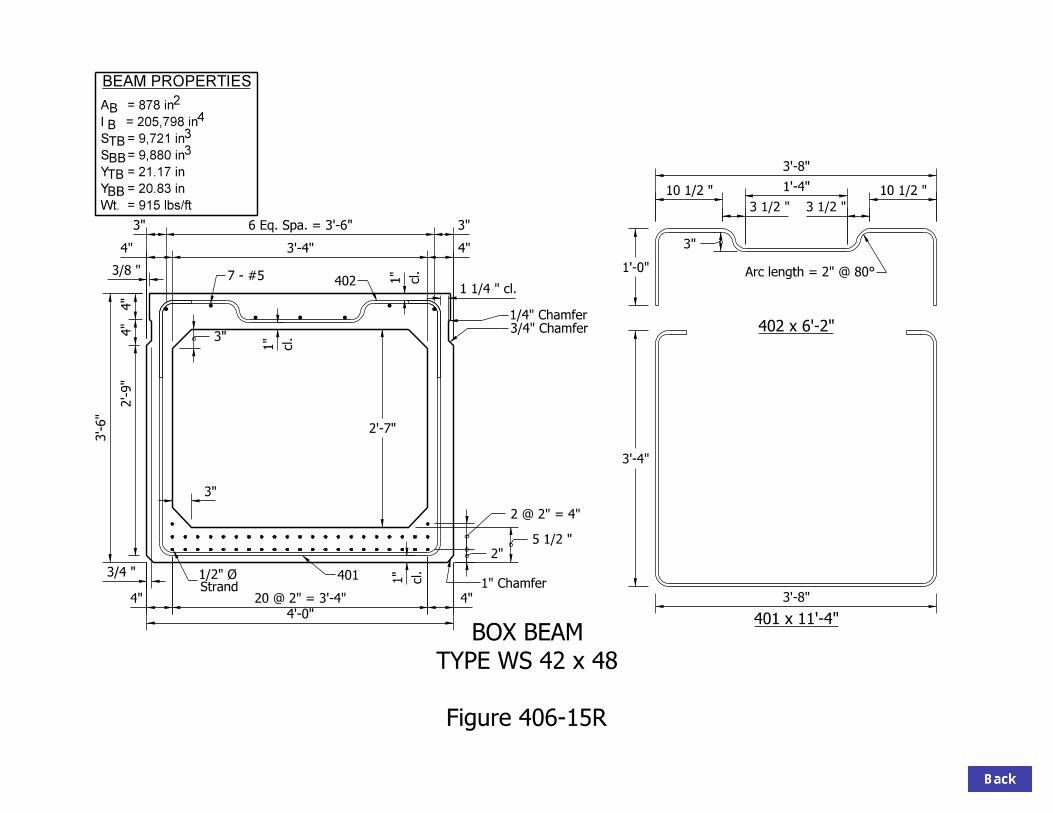
402 x 6’-2"
B2
B
TB
BB
TB
BB
4
3
3
BEAM PROPERTIES
A = 878 in
S = 9,721 in
S = 9,880 in
Y = 21.17 in
Wt. = 915 lbs/ft
1 1/4 " cl.
4’-0"
3/8 "
3’-6"
3/4 "
4" 4"Strand1/2" Ø 401 c
l.
1"
1" Chamfer
7 - #5 402
3/4" Chamfer
1/4" Chamfer
2’-9"
4"
4"
Y = 20.83 in
cl.
1"
3"
3"
5 1/2 "
2’-7"
3"6 Eq. Spa. = 3’-6"3"
cl.
1"
2 @ 2" = 4"
2"
20 @ 2" = 3’-4"
3’-8"
3"
1’-0"
10 1/2 " 1’-4" 10 1/2 "
3 1/2 "3 1/2 "
3’-4"
3’-8"
Arc length = 2" @ 80°
401 x 11’-4"
I = 205,798 in
Figure 406-15R
TYPE WS 42 x 48
BOX BEAM
4"3’-4"4"

DIMENSION.
*THIS IS A MINIMUM
I-BEAM PIER DIAPHRAGM
SECTION BETWEEN BEAMS
Figure 406-16A
BEARING PADS)
(SAME HEIGHT AS
EXPANDED POLYSTYRENE
(BONDED TO THE CONCRETE)
AND 1" EACH END OF KEYWAY)
(1/2" BOTTOM, 1" EACH SIDE
EXPANDED POLYSTYRENE
2"
Cl.
5" (Typ.)
2" Cl. (Typ.)
#5 @ 1’-0" MAX.
#5 BTWN. BEAMS
#6 THRU BEAM
1’-3"1’-3"
2’-6"
BETWEEN BEAMS
3" x 1’-0" KEYWAY

BEARING PADS)
(SAME HEIGHT AS
EXPANDED POLYSTYRENE
DIMENSION.
*THIS IS A MINIMUM
5" (Typ.)
I-BEAM PIER DIAPHRAGM
SECTION AT BEAMS
Figure 406-16B
BEARING PAD
ELASTOMERIC
THRU BEAM HOLE W/ #6À1"
1’-3"1’-3"
2’-6"
BENT-UP STRANDS#8

3" (Typ.)
2" Cl. (Typ.)
2"
Cl.
9"
I-BEAM
INTERMEDIATE DIAPHRAGM
Figure 406-16C
BTWN. BEAMS
#5@1’-0" MAX.
#6 THRU BEAM
#4@1’-0" MAX.

PIER
INTERMEDIATE
#5
#5 @ 1’-0" Max.
THREADED INSERTÀ"43
#6 THREADED BAR IN
THREADED INSERTÀ"43
#6 THREADED BAR IN #5 @ 1’-0" Max.
#4@1’-0" MAX.
HOLE
À#6 THRU 1"#5 LAP
HOLE
À#6 THRU 1" #5 LAP
Figure 406-16D
DIAPHRAGMS
I-BEAM

THIS DIMENSION SHOULD BE INCREASED FOR LARGE EXPANSION LENGTH.
CHECK SEISMIC MINIMUM SUPPORT LENGTH FOR EXPANSION BENT.
USE FOR SIZING CAP ONLY.ROUND UP TO AN INCREMENT OF 3"
E = B + D
ACTUAL D = E - B
F = B - (0.5E)
G = F sec
A = (1’-4") sec + 10" + 0.5 (L + W tan )
B = A cos
C = 0.5 (L + W tan ) + sec
D = C cos
BENTˆ
BEARINGˆ
BEARING PAD
ELASTOMERIC
6"
Min.1"
4"
1’-0"
6"
LEDGE
PAVEMENT
6" Min.
BOTTOM FLANGE
W
1"
Min.
1"
Min.
E
L
CA
F
G
D
BB.F. MUDWALL
F.F. MUDWALL
I-BEAM: END BENT CAP SIZINGAND BEARING LAYOUT DETAILS
Figure 406-16E

C = B cos
CAP WIDTH = 2AC
ACTUAL C = 1/2 CAP WIDTH - A
USE FOR SIZING CAP ONLY.ROUND UP TO AN INCREMENT OF 3"
USE 6" FOR PIER BELOW EXPANSION JOINT.
BEARINGˆ
BEARING PAD
ELASTOMERIC
PIERˆ
BOTTOM FLANGE
9"9"
6"
3"3"
6"
4" Min.
B
W
1"
Min.
1"
Min.
CA
L
1" Min.
A = 9" cos
B = 0.5 (L + W tan ) + 4" sec
Figure 406-16F
BEARING LAYOUT DETAILS
I BEAM: PIER CAP SIZING AND

A
B
C
D
BEAMˆ
3"
c
b
a
1’-3"
10"
5"
2’-6" MIN. DIAPHRAGM
A = a + b
B = a + c
C = a - c
D = a - b
ARE NOT VERTICAL. SEE SECTION 63-12.0 FOR ADDITIONAL INFORMATION.
THIS DIMENSION WILL INCREASE OR DECREASE SLIGHTLY IF ENDS OF BEAMS
1. IF D < 2" USE LARGER DIAPHRAGM.
NOTES:
c = 1/2 Web Thickness (tan )
b = 1/2 Bottom Flange Width (tan )
a = (10" - cos ) - 3"
2. A MINUS B AND C MINUS D SHOULD BE MADE EQUAL
Figure 406-16G
HOLES AT PIER DIAPHRAGM
I-BEAM

BEARING PADS)
(SAME HEIGHT AS
EXPANDED POLYSTYRENE
DIMENSION.
*THIS IS A MINIMUM
5" (Typ.)
2" Cl. (Typ.)
2"
Cl.
#5 BTWN. BEAMS
#5 @ 1’-0" MAX.
(BONDED TO THE CONCRETE)
AND 1" EACH END OF KEYWAY)
(1/2" BOTTOM, 1" EACH SIDE
EXPANDED POLYSTYRENE
3’-0"
1’-6"1’-6"
#6 THUR BEAM
BETWEEN BEAMS
3" x 1’-0" KEYWAY
BULB-TEE PIER DIAPHRAGM
SECTION BETWEEN BEAMS
Figure 406-16H

BEARING PAD
ELASTOMERIC
BEARING PADS)
(SAME HEIGHT AS
EXPANDED POLYSTYRENE
BENT UP STRANDS
5"
DIMENSION.
THIS IS A MINIMUM
#8
#6 THRU BEAM
HOLE W/À1"
3’-0"
1’-6" 1’-6"
BULB-TEE PIER DIAPHRAGM
SECTION AT BEAMS
Figure 406-16 I
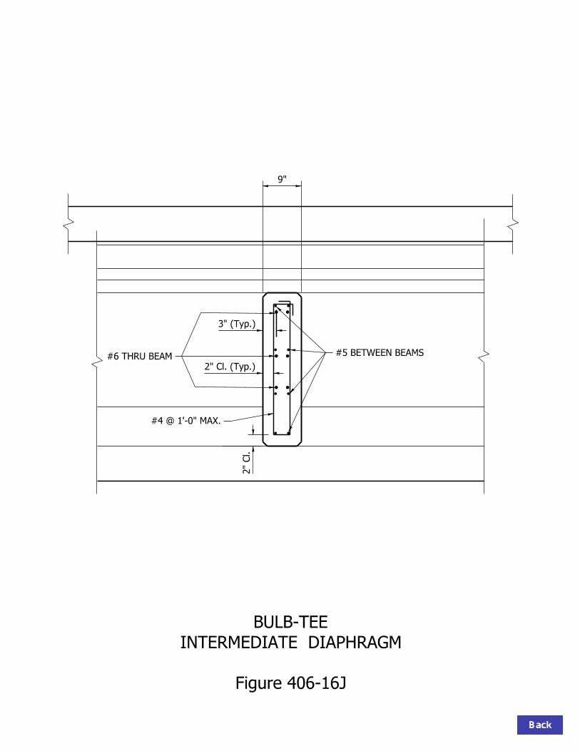
BULB-TEE
INTERMEDIATE DIAPHRAGM
Figure 406-16J
#4 @ 1’-0" MAX.
3" (Typ.)
2" Cl. (Typ.)
2"
Cl.
9"
#5 BETWEEN BEAMS#6 THRU BEAM

BULB-TEE
DIAPHRAGM
Figure 406-16K
INTERMEDIATE
PIER
#5#5@1’-0" MAX.
INSERT
THREADEDÀ"43IN
#6 THREADED BAR
#5 LAP
#5@1’-3" MAX.#4@1’-0" MAX.
#5 LAP
HOLEÀ1"
#6 THRU
INSERT
THREADEDÀ"43IN
#6 THREADED BAR
HOLEÀ1"
#6 THRU

THIS DIMENSION SHOULD BE INCREASED FOR LARGE EXPANSION LENGTH.
CHECK SEISMIC MINIMUM SUPPORT LENGTH FOR EXPANSION BENT.
USE FOR SIZING CAP ONLY.ROUND UP TO AN INCREMENT OF 3"
E = B + D
ACTUAL D = E - B
F = B - (0.5E)
G = F sec
BEARINGˆ
BEARING PAD
ELASTOMERIC
LEDGE
PAVEMENT
BOTTOM FLANGE
W
E
L
CA
F
G
D
BB.F. MUDWALL
F.F. MUDWALL
4"
1’-0"
6"
Min.2"
9"
1"
Min.
1"
Min.
6" Min.
BULB-TEE: END BENT CAP SIZINGAND BEARING LAYOUT DETAILS
Figure 406-16L
B = A cos
C = 0.5 (L + W tan ) + sec
D = C cos
A = (1’-4") sec + 9" + 0.5 (L + W tan )

USE FOR SIZING CAP ONLY.ROUND UP TO AN INCREMENT OF 3"
BEARING PAD
ELASTOMERIC
BULB TEE: PIER CAP SIZING ANDBEARING LAYOUT DETAILS
Figure 406-16M
C = B cos
ACTUAL C = 1/2 CAP WIDTH - A
USE 6" FOR PIER BELOW EXPANSION JOINT
A = 1 cos
B
W
MIN.2"
L
1"
MIN.
1"
MIN.
BOTTOM FLANGE
BEARINGˆ
Pierˆ
4" MIN.
1’-0" 1’-0"
9"
3"3"
9"
A
C
B = 0.5 (L + W tan ) + 4" sec
CAP WIDTH = 2(A+C)

3"
1’-6"
5"
1’-1"
"2
11’-0
"2
13
A
E
D
CB
d
c
a
b
BEAMˆ
A = E + a
B = E + b
C = E - b
D = E - a
ARE NOT VERTICAL. SEE SECTION 63-12.0 FOR ADDITIONAL INFORMATION.
THIS DIMENSION WILL INCREASE OR DECREASE SLIGHTLY IF ENDS OF BEAMS
NOTE:
Figure 406-16N
HOLES AT PIER DIAPHRAGM
BULB-TEE
IF D OR d IS < 2" USE LARGER DIAPHRAGM.
c = (1’-6") sec
E = (1’-1") sec - 3"
WIDTH DIAPHRAGM
3’-0" MIN.
DIAPH.ˆ
") (tan )21
a = (1’-0
") (tan )21
b = (3
d = (5") (sec )

BEARING PADS)
(SAME HEIGHT AS
EXPANDED POLYSTYRENE
5" (Typ.)
2" Cl. (Typ.)
2"
Cl.
#5 BTWN. BEAMS
#4 @ 1’-0" MAX.
(BONDED TO THE CONCRETE)
AND 1" EACH END OF KEYWAY)
(1/2" BOTTOM, 1" EACH SIDE
EXPANDED POLYSTYRENE
DIMENSION.
*THIS IS A MINIMUM
1’-0" 1’-0"
2’-0"
BEAM @1’-0" MAX.
#6 THREADED BAR FROM
BETWEEN BEAMS
3" x 1’-0" KEYWAY
BOX BEAM PIER DIAPHRAGM FOR SPREAD BEAMS
SECTION BETWEEN BEAMS
Figure 406-16 O
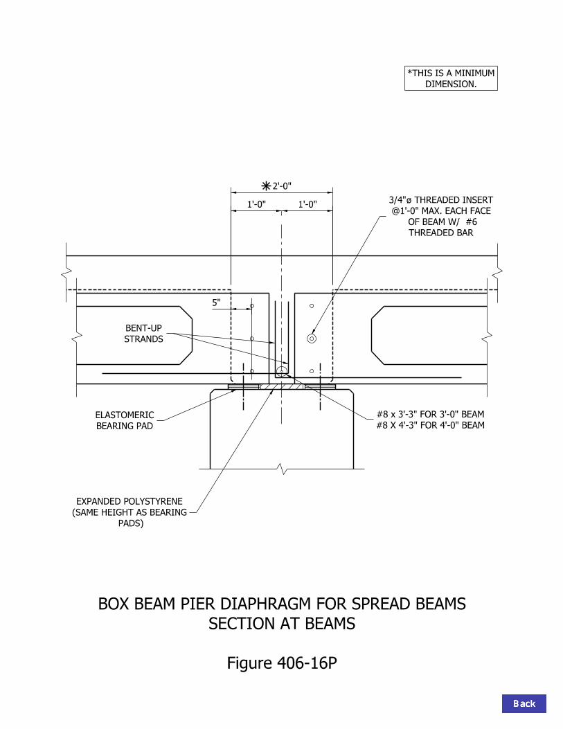
DIMENSION.
*THIS IS A MINIMUM
BOX BEAM PIER DIAPHRAGM FOR SPREAD BEAMS
SECTION AT BEAMS
Figure 406-16P
BEARING PAD
ELASTOMERIC
STRANDS
BENT-UP
5"
1’-0" 1’-0"
2’-0"
THREADED BAR
OF BEAM W/ #6
@1’-0" MAX. EACH FACE
THREADED INSERTÀ3/4"
PADS)
(SAME HEIGHT AS BEARING
EXPANDED POLYSTYRENE
#8 X 4’-3" FOR 4’-0" BEAM
#8 x 3’-3" FOR 3’-0" BEAM

Figure 406-16Q
AT PIER
BOX BEAM DIAPHRAGM
#5
#5 LAP
#4 @ 1’-0" MAX.
THREADED INSERT"ÀIN 3/4
#6 THREADED BAR @ 1’-0" MAX.

BEARING PAD
ELASTOMERIC
BEARING PADS)
(SAME HEIGHT AS
EXPANDED POLYSTYRENE
#8
(BONDED TOTHE CONCRETE)
AND 1" EACH END OF KEYWAY)
(1/2" BOTTOM, 1" EACH SIDE
EXPANDED POLYSTYRENE
Figure 406-16R
FOR ADJACENT BEAMS
CLOSURE POUR AT PIER
BOX BEAM
STRANDS
BENT-UP
3" x 8" KEYWAY

CHECK SEISMIC MINIMUM SUPPORT LENGTH FOR EXPANSION BENT.
USE FOR SIZING CAP ONLY.ROUND UP TO AN INCREMENT OF 3"
ACTUAL C = D - B
F = E sec
B = A cos
D = B + C
E = B - 0.5 D
B.F. MUDWALL
F.F. MUDWALL
LEDGE
PAVEMENT
BEARING PAD
ELASTOMERIC
BEARINGˆ
BENTˆ
D
B
C6"
MIN.
9" (T
YP.)
PADˆ
6"
A
E
F
6"
1’-0"
4"
L
A = (1’-4") sec + 6"
C = 0.5 L + 6"
BOX BEAM: END BENT CAP SIZINGAND BEARING LAYOUT DETAILS
Figure 406-16S

BEARING PAD
ELASTOMERIC
USE FOR SIZING CAP ONLY.ROUND UP TO AN INCREMENT OF 3"
CAP WIDTH = 2AB
ACUTAL B = 1/2 CAP WIDTH - A
BOX BEAM: PIER CAP SIZING ANDBEARING LAYOUT DETAILS
FOR SPREAD BEAMS
Figure 406-16T
BENTˆ
BEARINGˆ
B
A
L
PADˆ
4" MIN.
9" (T
YP.)
6"
3" 3"
6"
9"9"
A = 9" cos
B = 0.5L + 4"
USE 0.5 ft. FOR PIER BELOW EXPANSION JOINT.
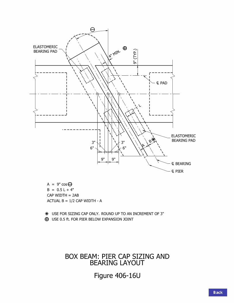
USE FOR SIZING CAP ONLY.ROUND UP TO AN INCREMENT OF 3"
BOX BEAM: PIER CAP SIZING AND BEARING LAYOUT
Figure 406-16U
CAP WIDTH = 2AB
ACTUAL B = 1/2 CAP WIDTH - A
A = 9" cos
B = 0.5 L + 4"
BEARING PAD
ELASTOMERIC
BEARING PAD
ELASTOMERIC
PADˆ
BEARINGˆ
PIERˆ
B
A
L
9" (T
YP.)
4" MIN.
9"9"
6"
3"3"
6"
USE 0.5 ft. FOR PIER BELOW EXPANSION JOINT

A
600 DIAPHRAGM
BOX BEAM
BEAMˆ
3"3"
5"
7"
1’-0"
A = ( 7" / COS ) - 3" = ___________
BOX BEAMINSERTS AT PIER DIAPHRAGM
Figure 406-16V

1 1/4" CLR. OFF HEADBOARDPLACE PARALLEL TO BEAM END.
2-404 PER BEAM END,
1’-6" Start of Void
#5
1 1/2 " Cl.
MINUS 5"BEAM DEPTH
TYPICAL END REINFORCEMENT SECTION404 BAR
403 BAR
TYPICAL END REINFORCEMENT PLAN
45°
MINUS 3 1/2"BEAM DEPTH
(403 Spa.) = 2’-6"5 Eq. Spa.
Min. Lap
1’-0"
3’-0"
2’-5"
3’-0"
(Typ.)Strand1/2" Ø
#5 (Typ.)
403 (Typ.)
403
Per Design401 & 402
SKEW ANGLE
VARIES WITH
403
Figure 406-16W
SKEWED-BEAM END (45-deg Skew Shown)MILD REINFORCEMENT FOR 36 WIDTH

1 1/4" CLR. OFF HEADBOARDPLACE PARALLEL TO BEAM END.
3-404 PER BEAM END,
1’-6" Start of Void
#5
1 1/2 " Cl.
MINUS 5"BEAM DEPTH
TYPICAL END REINFORCEMENT SECTION404 BAR
403 BAR
TYPICAL END REINFORCEMENT PLAN
45°
MINUS 3 1/2"BEAM DEPTH
(403 Spa.) = 3’-6"7 Eq. Spa.
Min. Lap
1’-8"
4’-0"
3’-5"
4’-0"
403
(Typ.)Strand1/2" Ø
#5 (Typ.)
403 (Typ.)
403
Per Design401 & 402
SKEW ANGLE
VARIES WITH
Figure 406-16X
SKEWED-BEAM END (45-deg Skew Shown)MILD REINFORCEMENT FOR 48 WIDTH