
PRESERVING THE ENVIRONMENT DUE TO THE FLASH FLOODS … · Studies for Jetty Spur Design at Coastal...
11
PRESERVING THE ENVIRONMENT DUE TO THE FLASH FLOODS IN VELLAR RIVER AT TV PUTHUR, VIRUDHACHALAM TALUK, TAMIL NADU: A CASE STUDY Needhidasan S 1 *, Chenchu Babu K 2 , Natrayan M 2 , Naveen D C 2 and Vinothkumar S 2 Rivers are seldom straight. Depending on discharge, slope and sediments, some stretches are meandering with alternate bends while some stretches are braided with main and branches within the same flood plain. Usually a river is found to erode the outer bank and sediments get deposited on inner bank and thus causes major problem of that particular region. In the present study this problem has occurred frequently in Vellar River in Cuddalore District at every monsoon. Spur and retaining wall has been designed with the help of IS codal provisions and existing methods adopted by Experts and Engineers of PWD, Govt. of Tamil Nadu. It has been found that some modifications in design, care during construction and maintenance would enhance the performance of the spur. The construction of RCC spur will not only protect the river bank but also the adjacent patta lands and cultivable lands in the study area. Keywords: Discharge, Environment, Flash floods, Impermeable Spurs, Meandering, Retaining wall 1 Saveetha School of Engineering, Saveetha University, Chennai, Tamil Nadu, India. 2 Department of Civil Engineering, Indira Institute of Engineering & Technology, Tiruvallur, Tamil Nadu, India. *Corresponding Author:S Needhidasan, [email protected] ISSN 2319 – 6009 www.ijscer.com Vol. 2, No. 3, August 2013 © 2013 IJSCER. All Rights Reserved Int. J. Struct. & Civil Engg. Res. 2013 Case Study INTRODUCTION India is gifted with river systems and many of these rivers are perennial and some of these are seasonal. Unfortunately deterioration in the water quality from these systems due to anthropogenic activities makes the water unfit for its intended use. But the other side of the problem is excess in quantity without proper control over it, erodes the nearby area including cultivable lands which again a problem to the community. Flooding is the most common of all environmental hazards (Smith, 2001). Catastrophic floods endanger lives and cause human tragedy as well as heavy economic losses. Floods being a natural phenomenon, total elimination or control of floods is neither practically possible nor economically viable. Hence, flood
Transcript of PRESERVING THE ENVIRONMENT DUE TO THE FLASH FLOODS … · Studies for Jetty Spur Design at Coastal...
104
Int. J. Struct. & Civil Engg. Res. 2013 Needhidasan S et al., 2013
PRESERVING THE ENVIRONMENT DUETO THE FLASH FLOODS IN VELLAR RIVERAT TV PUTHUR, VIRUDHACHALAM TALUK,
TAMIL NADU: A CASE STUDY
Needhidasan S1*, Chenchu Babu K2, Natrayan M2, Naveen D C2 and Vinothkumar S2
Rivers are seldom straight. Depending on discharge, slope and sediments, some stretches aremeandering with alternate bends while some stretches are braided with main and brancheswithin the same flood plain. Usually a river is found to erode the outer bank and sediments getdeposited on inner bank and thus causes major problem of that particular region. In the presentstudy this problem has occurred frequently in Vellar River in Cuddalore District at every monsoon.Spur and retaining wall has been designed with the help of IS codal provisions and existingmethods adopted by Experts and Engineers of PWD, Govt. of Tamil Nadu. It has been foundthat some modifications in design, care during construction and maintenance would enhancethe performance of the spur. The construction of RCC spur will not only protect the river bankbut also the adjacent patta lands and cultivable lands in the study area.
Keywords: Discharge, Environment, Flash floods, Impermeable Spurs, Meandering, Retainingwall
1 Saveetha School of Engineering, Saveetha University, Chennai, Tamil Nadu, India.2 Department of Civil Engineering, Indira Institute of Engineering & Technology, Tiruvallur, Tamil Nadu, India.
*Corresponding Author:S Needhidasan, [email protected]
ISSN 2319 – 6009 www.ijscer.comVol. 2, No. 3, August 2013
© 2013 IJSCER. All Rights Reserved
Int. J. Struct. & Civil Engg. Res. 2013
Case Study
INTRODUCTIONIndia is gifted with river systems and many ofthese rivers are perennial and some of theseare seasonal. Unfortunately deterioration in thewater quality from these systems due toanthropogenic activities makes the water unfitfor its intended use. But the other side of theproblem is excess in quantity without propercontrol over it, erodes the nearby area
including cultivable lands which again aproblem to the community. Flooding is themost common of all environmental hazards(Smith, 2001). Catastrophic floods endangerlives and cause human tragedy as well asheavy economic losses. Floods being anatural phenomenon, total elimination orcontrol of floods is neither practically possiblenor economically viable. Hence, flood
105
Int. J. Struct. & Civil Engg. Res. 2013 Needhidasan S et al., 2013
management aims at providing a reasonabledegree of protection against flood damage ateconomic costs and preserves theenvironment. Structural measures includestorage reservoirs, flood embankments,drainage channels, anti-erosion works, channelimprovement works, detention basins and non-structural measures include flood forecasting,flood plain zoning, flood proofing, disasterpreparedness, etc. The river systems provideirrigation, potable water, cheap transportation,electricity, as well as provide livelihoods for alarge number of people all over the country.However, the river waters can be utilized onlyif the rivers are properly trained and controlled.
A predominant characteristic of alluvial riveror channel is the change in location and shapethat the channel and cross section experiencewith time. These changes are particularlysignificant during periods when alluvialchannels are subjected to comparatively highfloods. Regardless of the fact that the majorityof bank changes occur during short monsoonperiods, there may also be regions within ariver in which some degree of instability isexhibit for all flood conditions. This study aimedto discuss the forces affecting the behavior orrivers, analyze the existing condition of the river.It also suggests some remedial measures tocontrol bank erosion and their potentialimpacts upon the river.
FLOODING AND MEANDERINGFlooding is a natural part of a river’s cycle. Themajority of the erosion of river channels andthe erosion and deposition on the associatedfloodplains occur during flood stage. In manydeveloped areas, human activity has changedriver channel form, altering different magnitudes
and frequencies of flooding. In many caseshuman activities in rivers and floodplains havedramatically increased the risk of flooding.Straightening rivers allows water to flow morerapidly downstream increasing the risk offlooding places further downstream. Buildingon flood plains removes flood storage whichagain exacerbates downstream flooding. Thebuilding of levees may only protect the areabehind the levees and not those furtherdownstream. Levees and flood-banks can alsoincrease flooding upstream because of back-water pressure as the upstream water has tosqueeze between the levees. Rivers in factflow downhill regardless of compass direction.Sometimes downhill is from north to south, butequally it can be from south to north, andusually is a complex meandering path involvingall directions of the compass. Rivers flowingdownhill, from river source to river mouth, donot necessarily take the shortest path. Foralluvial streams, straight and braided rivershave very low sinuosity and flow directlydownhill, while meandering rivers flow from sideto side across a valley.
VELLAR RIVER AT T V PUTHUR,VIRUDHACHALAM TALUK: ACASE STUDYThe Vellar River originates in the Chitteri Hillsof Dharmapuri district in the name ofAnaimaduvu River and drains into Bay ofBengal near Parangipettai in Chidambaramtaluk of Cuddalore District. It has six tributariesnamely Anaimaduvu, Swethanadhi, Kallar,Chinnar, Manimukthanadhi and Gomukhi,which are vulnerable during flood seasons.Manimukthanadhi, which is the major tributary,also originates from Kalvarayan hills in
106
Int. J. Struct. & Civil Engg. Res. 2013 Needhidasan S et al., 2013
Villupuram district, traverses 111 km andjoins Vellar River near Srimushnam inChidambaram taluk of Cuddalore District. TheVellar River Basin is located in the NorthernPart of Tamil Nadu, between the latitudes 11°13’N - 12 00' N and longitude 78° 13’E - 79°47 E. The total area of the basin is 7520.87sq.km and the total length of the river is about150 km.
For Vellar and Manimukthanadhi, the riverbed slope is steeper. Both the rivers areoriginating from the foot of the hills and due tothe hilly terrain, the rate of runoff is very highand the flood water meanders by forming sanddeposit on one side and causing erosion onthe other side of the bank. Sometimes theflood water erodes the bank and enters thepatta (cultivable) lands adjacent to the bankwhich threatens the survival of the local people.Due to heavy and unprecedented rain duringthe November 2009 heavy flood occurred bothin vellar and manimuktha river and dischargeda maximum of 2,07,000 Cusecs atGudalaiyathur Village, which is the confluencepoint of these rivers. Due to the sand depositformed on one side of bank along the rivercourse, the river could not be able to dischargethe flood water and causes erosion on theopposite side of the bank. It results in breachesof banks in many places from Tholudhurregulator to Sethiathope Regulator and overwashed banks and agricultural lands andportion of hamlet adjacent to the bank, all alongthe course of river and places such are TVPuthur, Semberi, etc., has been submerged.This leads causalities to human beings, livestocks and as well as the heavy loss to thepublic and private properties along the Vellarriver course in Thittagudi, Vriddhachalam,
Kattumanarkoil and Chidambaram Taluks inCuddalore District. In addition to the above,most of the cross masonry structures such asanaicuts, regulators, ramps, inlets and outletshave been damaged.
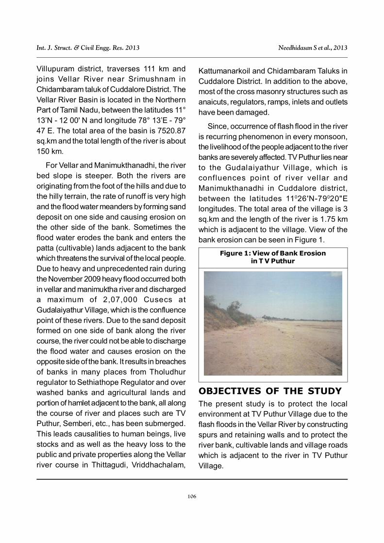
Since, occurrence of flash flood in the riveris recurring phenomenon in every monsoon,the livelihood of the people adjacent to the riverbanks are severely affected. TV Puthur lies nearto the Gudalaiyathur Village, which isconfluences point of r iver vel lar andManimukthanadhi in Cuddalore district,between the latitudes 11026'N-79020"Elongitudes. The total area of the village is 3sq.km and the length of the river is 1.75 kmwhich is adjacent to the village. View of thebank erosion can be seen in Figure 1.
Figure 1: View of Bank Erosionin T V Puthur
OBJECTIVES OF THE STUDYThe present study is to protect the localenvironment at TV Puthur Village due to theflash floods in the Vellar River by constructingspurs and retaining walls and to protect theriver bank, cultivable lands and village roadswhich is adjacent to the river in TV PuthurVillage.
107
Int. J. Struct. & Civil Engg. Res. 2013 Needhidasan S et al., 2013
And also to strengthen the Vellar river bankto carry maximum flood discharge and toprevent the live stocks, Agricultural and Pattalands and village roads, which is adjacent tothis to minimize the erosion and controlmeandering in this stretch by constructing aspur.
REVIEW OF LITERATUREKnowledge of sediment transport is importantto such endeavor as river restoration,ecosystem protection, etc., an alluvial river isa water body that flows through gravels, sands,silt or clay deposited by the flowing river. Withalluvial river the channel geometry is influencednot only by the flow of water but by the sedimenttransport by the water is studied by USGeological survey scientific investigationreport, Robert R Holmes (2010).
Natural alluvial rivers are usually wide withan aspect ratio (width to depth) of 10 or greater(Yalin and da Silva, 2001) and the boundarycan be molded into various configurations aswas demonstrated in the seminal work byGilbert (1914).
Uddin et al. (2011) reviews river bankerosion problem in Bangladesh in general,evaluates the performance of a new techniqueand identifies avenues for further improvementof this technique. This technique utilizesReinforced Cement Concrete (RCC) spur toachieve bank protection at a reasonable cost.In the last decade, around 38 RCC spurs havebeen constructed along the River Ganges,Jamuna, Teesta and Dudkumar inBangladesh. It has been found that somemodifications in design, care duringconstruction and maintenance would enhance
the performance of this new lost-cost river bankprotection technique.
William et al. (2008) prepared a guidelinesbased on Physical and Numerical ModelingStudies for Jetty Spur Design at Coastal Inletsin Coastal and Hydraulics Laboratory, USArmy Engineer Research and DevelopmentCenter. Results indicated that a submergedspur was as effective as a surface-piercingstructure in deflecting the seaward-movingcurrent along the jetty, potentially savingconstruction and maintenance costs.
Corrado Gisonni (2008), conducted aresearch investigated that the effects of avariety of parameters on spur flow, notably spurlength, spur spacing, spur height plus thediameter and the number of riprap rows, alongwith the main hydraulic parameters. Theyconclude with a set of limitations for theapplication of these results in river engineering.
Kothyari and Ranga Raju (2001) studies theprocedures used by the previous investigatorsfor determination of design scour depth insteady flows at abutments and spur dikes bymaking use of the design discharge. The timerequired by the design discharge to scour toits full potential is generally much larger thanthe time for which it runs. Therefore,computations on temporal variation of scourdepth are also important for design purposes.
Spacing of spurs in series by using modelstudies of River Ganges conducted by Syedabdus Shoban and Swapan Kumar Das(1999), Institute of Engineers, Bangladesh.The study concludes that the spur spacingshould be 2-2.5 times in general and widelyused and they found that the spacing shouldbe 4.5-5 times the spur could protect the bank
108
Int. J. Struct. & Civil Engg. Res. 2013 Needhidasan S et al., 2013
effectively.
Ronald R Copeland (1983) a hydraulicmodel investigation was conducted to evaluateand demonstrate the effects of impermeablespur dikes as a bank protection technique ina concave bend. The tests were conducted toobserve channel bed and bank response in astream with non cohesive banks, wheresuspended load is insignificant. Severalparameters relative to spur dike design thatwere evaluated included: the length to spacingratio, the orientation angle, and the effect ofan apron or mattress of protection at the toeof the dike.
It has been found out the Spurs can bedesigned with adequate safety for controllingriver erosion. It requires design parametersthat are orientation, spacing, length, type andeffectiveness. The guidelines used for differentspurs differ in different countries based on theriver type and velocities. Physical model studyrequires for this training works and its function.It has been found that some modifications indesign, care during construction andmaintenance would enhance the performanceof this new lost-cost river bank protectiontechnique.
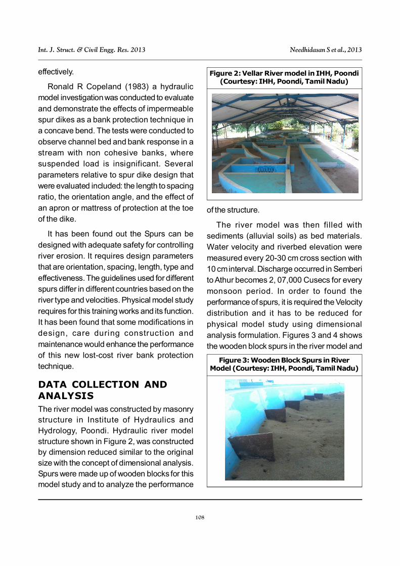
DATA COLLECTION ANDANALYSISThe river model was constructed by masonrystructure in Institute of Hydraulics andHydrology, Poondi. Hydraulic river modelstructure shown in Figure 2, was constructedby dimension reduced similar to the originalsize with the concept of dimensional analysis.Spurs were made up of wooden blocks for thismodel study and to analyze the performance
of the structure.
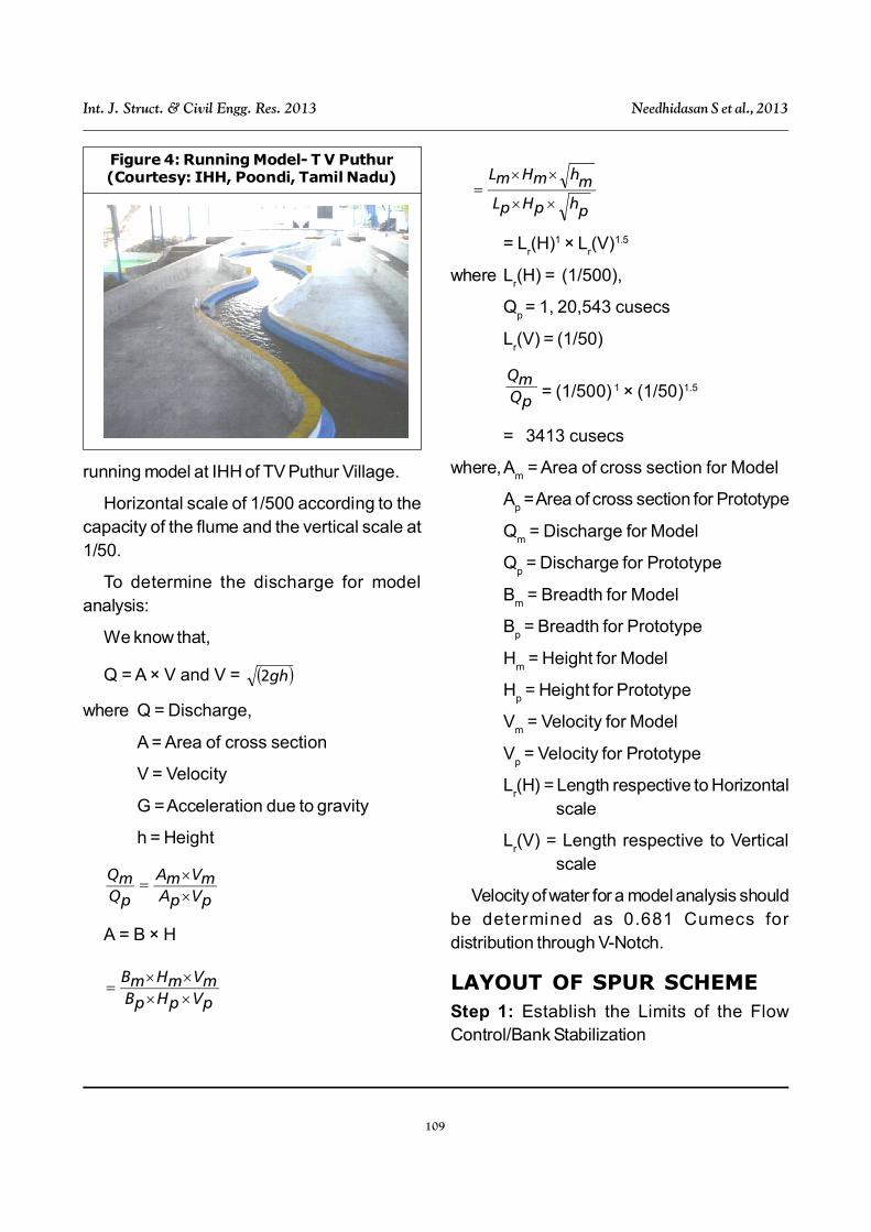
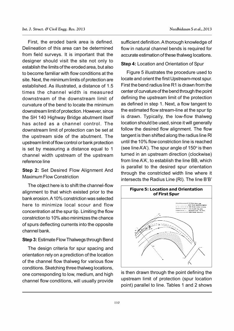
The river model was then filled withsediments (alluvial soils) as bed materials.Water velocity and riverbed elevation weremeasured every 20-30 cm cross section with10 cm interval. Discharge occurred in Semberito Athur becomes 2, 07,000 Cusecs for everymonsoon period. In order to found theperformance of spurs, it is required the Velocitydistribution and it has to be reduced forphysical model study using dimensionalanalysis formulation. Figures 3 and 4 showsthe wooden block spurs in the river model and
Figure 2: Vellar River model in IHH, Poondi(Courtesy: IHH, Poondi, Tamil Nadu)
Figure 3: Wooden Block Spurs in RiverModel (Courtesy: IHH, Poondi, Tamil Nadu)
109
Int. J. Struct. & Civil Engg. Res. 2013 Needhidasan S et al., 2013
running model at IHH of TV Puthur Village.
Horizontal scale of 1/500 according to thecapacity of the flume and the vertical scale at1/50.
To determine the discharge for modelanalysis:
We know that,
Q = A × V and V = gh2
where Q = Discharge,
A = Area of cross section
V = Velocity
G = Acceleration due to gravity
h = Height
pVpAmVmA
pQmQ
A = B × H
pVpHpBmVmHmB
phpHpLmhmHmL
= Lr(H)1 × L
r(V)1.5
where Lr(H) = (1/500),
Qp = 1, 20,543 cusecs
Lr(V) = (1/50)
pQmQ
= (1/500) 1 × (1/50)1.5
= 3413 cusecs
where,Am = Area of cross section for Model
Ap = Area of cross section for Prototype
Qm = Discharge for Model
Qp = Discharge for Prototype
Bm = Breadth for Model
Bp = Breadth for Prototype
Hm = Height for Model
Hp = Height for Prototype
Vm = Velocity for Model
Vp = Velocity for Prototype
Lr(H) = Length respective to Horizontal
scale
Lr(V) = Length respective to Vertical
scale
Velocity of water for a model analysis shouldbe determined as 0.681 Cumecs fordistribution through V-Notch.
LAYOUT OF SPUR SCHEMEStep 1: Establish the Limits of the FlowControl/Bank Stabilization
Figure 4: Running Model- T V Puthur(Courtesy: IHH, Poondi, Tamil Nadu)
110
Int. J. Struct. & Civil Engg. Res. 2013 Needhidasan S et al., 2013
First, the eroded bank area is defined.Delineation of this area can be determinedfrom field surveys. It is important that thedesigner should visit the site not only toestablish the limits of the eroded area, but alsoto become familiar with flow conditions at thesite. Next, the minimum limits of protection areestablished. As illustrated, a distance of 1.5times the channel width is measureddownstream of the downstream limit ofcurvature of the bend to locate the minimumdownstream limit of protection. However, sincethe SH 140 Highway Bridge abutment itselfhas acted as a channel control . Thedownstream limit of protection can be set atthe upstream side of the abutment. Theupstream limit of flow control or bank protectionis set by measuring a distance equal to 1channel width upstream of the upstreamreference line
Step 2: Set Desired Flow Alignment AndMaximum Flow Constriction
The object here is to shift the channel-flowalignment to that which existed prior to thebank erosion. A 10% constriction was selectedhere to minimize local scour and flowconcentration at the spur tip. Limiting the flowconstriction to 10% also minimizes the chanceof spurs deflecting currents into the oppositechannel bank.
Step 3: Estimate Flow Thalwegs through Bend
The design criteria for spur spacing andorientation rely on a prediction of the locationof the channel flow thalweg for various flowconditions. Sketching three thalweg locations,one corresponding to low, medium, and highchannel flow conditions, will usually provide
sufficient definition. A thorough knowledge offlow in natural channel bends is required foraccurate estimation of these thalweg locations.
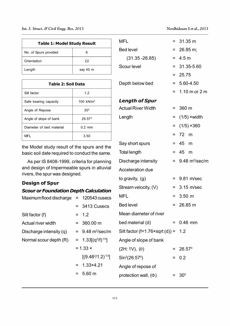
Step 4: Location and Orientation of Spur
Figure 5 illustrates the procedure used tolocate and orient the first Upstream-most spur.First the bend radius line R1 is drawn from thecenter of curvature of the bend through the pointdefining the upstream limit of the protectionas defined in step 1. Next, a flow tangent tothe estimated flow stream-line at the spur tipis drawn. Typically, the low-flow thalweglocation should be used, since it will generallyfollow the desired flow alignment. The flowtangent is then shifted along the radius line Rluntil the 10% flow constriction line is reached(see line A’A’). The spur angle of 150o is thenturned in an upstream direction (clockwise)from line A’A’, to establish the line BB, whichis parallel to the desired spur orientationthrough the constricted width line where itintersects the Radius Line (Rl). The line B’B’
Figure 5: Location and Orientationof First Spur
is then drawn through the point defining theupstream limit of protection (spur locationpoint) parallel to line. Tables 1 and 2 shows
111
Int. J. Struct. & Civil Engg. Res. 2013 Needhidasan S et al., 2013
the Model study result of the spurs and thebasic soil date required to conduct the same.
As per IS 8408-1999, criteria for planningand design of Impermeable spurs in alluvialrivers, the spur was designed.
Design of Spur
Scour or Foundation Depth Calculation
Maximum flood discharge = 120543 cusecs
= 3413 Cusecs
Silt factor (f) = 1.2
Actual river width = 360.00 m
Discharge intensity (q) = 9.48 m3/sec/m
Normal scour depth (R) = 1.33[(q2/f) 1/3]
= 1.33 ×
[(9.482/1.2) 1/3]
= 1.33×4.21
= 5.60 m
MFL = 31.35 m
Bed level = 26.85 m;
(31.35 -26.85) = 4.5 m
Scour level = 31.35-5.60
= 25.75
Depth below bed = 5.60-4.50
= 1.10 m or 2 m
Length of Spur
Actual River Width = 360 m
Length = (1/5) ×width
= (1/5) ×360
= 72 m
Say short spurs = 45 m
Total length = 45 m
Discharge intensity = 9.48 m3/sec/m
Acceleration due
to gravity, (g) = 9.81 m/sec
Stream velocity, (V) = 3.15 m/sec
MFL = 3.50 m
Bed level = 26.85 m
Mean diameter of river
bed material (d) = 0.46 mm
Silt factor (f=1.76×sqrt (d)) = 1.2
Angle of slope of bank
(2H: 1V), () = 26.570
Sin2(26.570) = 0.2
Angle of repose of
protection wall, () = 300
Table 1: Model Study Result
No. of Spurs provided 6
Orientation 22
Length say 45 m
Table 2: Soil Data
Silt factor 1.2
Safe bearing capacity 100 kN/m2
Angle of Repose 300
Angle of slope of bank 26.570
Diameter of bed material 0.2 mm
MFL 3.50
112
Int. J. Struct. & Civil Engg. Res. 2013 Needhidasan S et al., 2013
Sin2(300) = 0.25
Value of [K=
(1–(sin2 /sin2))1/2] = 0.447214
Specific gravity of
Boulders, (SS) = 2.65
Weight of Boulders Required(Minimum)
W = 0.02323 × SS ×
V6/(K× (SS-1)3)
where K = [ 1–(Sin2 /Sin2 )]1/2
Ss
= Specific gravity
of stone
= Angle of repose
of material of
protection
works
= Angle of
sloping bank
V = Velocity at
bank
= 30.16958 Kg
or say =50 kg
Top of Spur
Free board = 1.00 m
MFL = 3.50 m
Average height of spur = MFL +
free board
= 3.50+1.00
Height above bed = 4.50 m
The dimensions of Retaining wall, stem,
heel slab and stabilizing calculations weredesigned as per IS codal provisions.
RESULTS AND DISCUSSIONThe physical model, through which the flow ofwater is studied similar to the floods in field,helped a lot to know the actual fact of the studyarea. The spur and retaining work is designedfor TV Puthur village is found to be safe and asuitable protection work for the Vellar River andthe design elements are incorporated as foundsuitable. The important conclusions in theplanning and design of spur are: The directionand orientation of the channel’s flow thalwegplays a major role in determining an acceptablespacing between individual spurs in a bank-stabilization scheme, Reducing the spacingbetween individual spurs below the minimumrequired to prevent bank erosion between thespurs results in a reduction of the magnitudeof flow concentration and local scour at thespur tip, The primary criterion for establishingan appropriate spur orientation for the spurswithin a given spur scheme is to provide ascheme that efficiently and economicallyguides the flow through the channel bend, whileprotecting the channel bank and minimizingthe adverse impacts to the channel system,Spur orientation does not in itself result in achange in the length of channel bank protectedfor a spur of given projected length. It is thegreater spur length parallel to the channel bankassociated with spurs oriented at steeperangles that results in the greater length ofchannel bank protected and It isrecommended that spurs within a retardance/diverter or diverter spur scheme be set withthe upstream-most spur at approximately 150o
to the main flow current at the spur tip, and with
113
Int. J. Struct. & Civil Engg. Res. 2013 Needhidasan S et al., 2013
subsequent spurs having incrementally smallerangles approaching a minimum angle of 90o
at the downstream end of the scheme.
As this is the regular happening during themonsoon, i t is the need to create anenvironmental awareness in the study area.This will help the villagers to preserve their livestocks, agricultural lands and also the life whichis in danger. Changes in the agricultural patternalong the river bank will also help them to someextent. Though providing spurs is mandatoryto preserve the environment, it is the need ofthe hour to create awareness and train thepeople living along the river bank to overcomethis natural disturbance in the technical andfeasible way.
ACKNOWLEDGMENTWe would like to thank Dr. P K Suresh, Ph.D(IITM), Executive Engineer, Anti-Sea ErosionDepartment, PWD, Chepauk, Govt of TamilNadu and Mr. K Balamurugan, AssistantEngineer, Water Resources Department,Irrigation Section, Pelandurai, CuddaloreDistrict, for helping and guiding us for doingthis study.
REFERENCES1. Apmann R P (1972), “Flow Processes in
Open Channel Bends,” Journal of theHydraulics Division, American Societyof Civil Engineers, Vol. 98, No. HY5,Proceedings Paper 8886.
2. Kryzanowski A, Brilly M, Rusjan S andSchnabl S (2013), “Review Structuralflood-protection measures referring toseveral European case studies”, Nat.Hazards Earth Syst. Sci. Discuss., Vol.1, pp. 247–274.
3. Brice J C, Blodget J C et al. (1978), “99Countermeasures for Hydraulic Problemsat Bridges”, Final Report, FederalHighway Administration, FHWA-RD-’78-162, Vol. 1 and 2.
4. Harley S Winer (2011), “Re-Engineeringthe Mississippi River as a SedimentDelivery System”, Journal of CoastalResearch, Special Issue, Vol. 59, pp.229-234.
5. Manali A Patel and Ankit D Patel (2013),“Study of Flood Protection Work on MenRiver at Tilakwad Village of NarmadaDistrict, Gujarat”, Indian Journal ofApplied Research, Vol. 3.
6. Millet R A and Yves-Perez J (1981),“Current USA Practice: Slurry WallSpecif ication”, Journal of theGeotechnical Engineering Division, Vol.107, pp. 1041-1055.
7. Shields F D Jr. (1982), “EnvironmentalFeatures for Flood Control Channels”,Water Res. Bulletin, Vol. 18, No. 5.
8. Brilly M (2001), “The integrated approachto flash flood management, in: Copingwith Flash Floods”, Gruntfest E andHandmer J (Eds.), Kluwer AcademicPublishers, Dordrecht, pp. 103-113.
9. Brown S A (1979), “Investigation ofMeander Migration and Control on theLoyalsock Creek Using a PhysicalModel”, Master’s Thesis, Submitted inPartial Fulfillment of the Requirement forthe Degree of Master of Science, ThePennsylvania State University, UniversityPark Pennsylvania.
114
Int. J. Struct. & Civil Engg. Res. 2013 Needhidasan S et al., 2013
10. Federal Highway Administration, 1983.“Laboratory Investigation of Flow ControlStructures for Highway StreamCrossings”, U S Department of Trans-portation, August.
11. Federal Highway Administration, 1984.“Selection and Design of Flow Controland Stream bank Stabilization Structures,Report No. FHWA/RD-83/099, USDepartment of Transportation, WashingtonDC.
12. Jansen P, Ph D et al. (1979), Principlesof River Engineering: The Non-TidalAlluvial River, Pitman Publishing Limited,London.
13. Keeley J-W (1971), “Bank Protection andRiver Control in Oklahoma”, FederalHighway Administration, Bureau ofPublic Roads, Oklahoma Division.
14. Richardson E V and Simons D B (1974),“Spurs and Guide Banks”, Open FileReport, Colorado State UniversityEngineering Research Center, FortCollins, Colorado, February.
15. Matthew Heberger, the Pacific Institute,
et al. (2009), “The Impacts of Sea-LevelRise on the California Coast”, CaliforniaClimate Change Center, May.
16. Simons D B, Li R M, Alawady M A andAndrew J W (1979), “Connecticut U.S.U.S River Stream bank Erosion Study,Massachusetts, New Hampshire, andVermont”, Prepared for U S Army Corpsof Engineers, New England Division,
17. Waltham Army Corps of Engineers(1978), “Interim Report to Congress; TheStream bank Erosion Control Evaluationand Demonstration Act of 1974”, Section32 Program Interim Report, September.
18. Gilligan N (2008), “Hydromorphology andRiver Enhancement for Flood RiskManagement in Ireland”, 4th ECRRConference on River Restoration Italy,Venice S Servolo Island 16-21June 2008.
19. Kundzewicz Z W (2000), “Floodprotection in the context of sustainabledevelopment”, The Extremes of theExtremes: Extraordinary Floods,Proceedings of a symposium held atReykjavik, Iceland, July, IAHS Publ. no.271, pp. 361-366, 2002.263.