PreservatIon Tech Notes - National Park Service
8
WILSON'S BRIDGE Chester County, Pennsylvania Introduction Iron truss bridges were an essential ele- ment of America's Steam Age. In the decades fo ll owing the Civil War, the combination of strength, durability and affordability made iron bridges a favored means of traversing a ravine or river. They were a symbol of industrial power, a testimony to engineering effi- ciency, and a source of local pride. Over the years, however, the increasing load capacity and widths required by succeeding generations of vehicles, as well as inadequate maintenance and wholesale replacement programs, have reduced their number dramatically. As a result of this decline, an increased emphasis is now being placed on iden- tifying and implementing methods to preserve as many of the remaining iron truss bridges as possible. One such effort involves Wilson's Bridge, a wrought iron bridge constructed in 1886 to cross Valley Creek in Tredyffrin Township, Pennsylvania. Also known as County Bridge #166, this span now lies within the boundary of Valley Forge National Historical Park. It was fabricated by the Phoenix Iron Company and con- structed by John Denithorne & Sons, both of nearby Phoenixville, Pennsylvania. Because of its location, connection to local industrial history, and the scarcity of wrought iron bridges still in use, Wilson's Bridge is recognized as a valuable park and com- munity resource, eligible for listing in the National Register of Historic Places. The bridge features a single-span Pratt pony truss, approximately sixty feet long and sixteen feet wide (see fig- ure J) . When first constructed in the late 19 th century, the bridge included an oak plank deck supported by timber stringers running parallel to the road- way. Stringers, in turn, rested upon four iron floor beams that hung from the superstructure by large U-shaped bolts. Fieldstone abutments supported the bridge with wingwalls extending down to the ground line. The bridge had undergone numer- ous repair campaigns over the past hundred years, some of which included substituting new materials and compo- nents. Between 1930 and 1940, the timber stringers were replaced with steel I-beam stringers. The deck had been replaced on four occasions, most recently (in the mid-1960s) with a nail- laminated wood deck and asphalt wear- ing surface. At the time of its rehabilitation in 1998, Wilson's Bridge carried a dead end road linking several residences and a park maintenance facility with the rest of the national park and county road system. The dirt road had a low average daily traffic level of approxi- mately thirty-five vehicles; it was more commonly used by hikers and horse- back riders travelling along the park's trail system. A four-person bridge Technical Preservation ServIces PreservatIon Tech Notes METALS NUMBERS Rehabilitating a Historic Truss Bridge Using a Fiber Reinforced Plastic Deck Chad Randl Technical Preservation Services National Park Service Substitute materials may be used to replace deteriorated or missing elements of a historic bridge provided the character of the historic resource is preserved.
Transcript of PreservatIon Tech Notes - National Park Service
WILSON'S BRIDGE Chester County, Pennsylvania
Introduction
Iron truss bridges were an essential element of America's Steam Age. In the decades following the Civil War, the combination of strength, durability and affordability made iron bridges a favored means of traversing a ravine or river. They were a symbol of industrial power, a testimony to engineering efficiency, and a source of local pride. Over the years, however, the increasing load capacity and widths required by succeeding generations of vehicles, as well as inadequate maintenance and wholesale replacement programs, have reduced their number dramatically. As a result of this decline, an increased emphasis is now being placed on identifying and implementing methods to preserve as many of the remaining iron truss bridges as possible. One such effort involves Wilson's Bridge, a wrought iron bridge constructed in 1886 to cross Valley Creek in Tredyffrin Township, Pennsylvania.
Also known as County Bridge #166, this span now lies within the boundary of Valley Forge National Historical Park. It was fabricated by the Phoenix Iron Company and constructed by John Denithorne & Sons, both of nearby Phoenixville, Pennsylvania. Because of its location, connection to local industrial history, and the scarcity of wrought iron bridges still in use, Wilson's Bridge is recognized as a valuable park and community resource, eligible for listing in
the National Register of Historic Places.
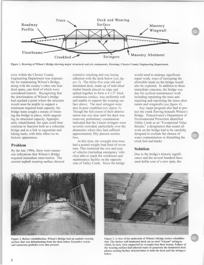
The bridge features a single-span Pratt pony truss, approximately sixty feet long and sixteen feet wide (see figure J). When first constructed in the late 19th century, the bridge included an oak plank deck supported by timber stringers running parallel to the roadway. Stringers, in turn, rested upon four iron floor beams that hung from the superstructure by large U-shaped bolts. Fieldstone abutments supported the bridge with wingwalls extending down to the ground line.
The bridge had undergone numerous repair campaigns over the past hundred years, some of which included substituting new materials and components. Between 1930 and 1940, the timber stringers were replaced with steel I-beam stringers. The deck had been replaced on four occasions, most recently (in the mid-1960s) with a naillaminated wood deck and asphalt wearing surface.
At the time of its rehabilitation in 1998, Wilson's Bridge carried a dead end road linking several residences and a park maintenance facility with the rest of the national park and county road system. The dirt road had a low average daily traffic level of approximately thirty-five vehicles; it was more commonly used by hikers and horseback riders travelling along the park's trail system. A four-person bridge
Technical Preservation ServIces
PreservatIon
Tech Notes METALS NUMBERS
Rehabilitating a Historic Truss Bridge Using a Fiber Reinforced Plastic Deck
Chad Randl Technical Preservation Services National Park Service
Substitute materials may be used to replace deteriorated or missing elements of a historic bridge provided the character of the historic resource is preserved.
Roadway Profile
Floorbeams
Deck and Wearing Surface Masonry
/Wingwall
---------------
Creekbed~ Stringers \ Masonry Abutment
Figure 1. Drawing of Wilson 's Bridge showing major structural and site components. Drawing: Chester County Engineering Department.
crew within the Chester County Engineering Department was responsible for maintaining Wilson's Bridge, along with the county 's other one hundred spans, one third of which were considered historic. Recognizing that the deterioration of Wilson's bridge had reached a point where the structure would soon be unable to support a minimum required load capacity, the bridge team sought a means of retaining the bridge in place, while upgrading its structural capacity. Appropriately rehabilitated, the span could then continue to function both as a vehicular bridge and as a link to equestrian and hiking trails, with little effect on its historic appearance.
Problem By the late 1990s, there were numerous indications that Wilson's Bridge required immediate intervention. The current asphalt wearing surface showed
extensive cracking and was losing adhesion with the deck below (see figure 2). The thirty-five year old naillaminated deck, made up of individual timber boards placed on edge and spiked together to form a 4-1/2" thick continuous surface, was uniformly soft and unable to support the wearing surface above. The steel stringers were also in poor condition (see figure 3) . Though the full extent of their deterioration was not clear until the deck was removed, preliminary examination indicated that the I-beam stringers were severely corroded, particularly over the abutments where they had suffered approximately fifty percent section loss.
At this time, the wrought iron truss had a posted weight load limit of seven tons. This restricted the size and type of vehicles (including emergency vehicles) able to reach the residences and maintenance facility on the opposite side of Valley Creek. Since the bridge
would need to undergo significant repair work, ways of increasing the allowable loads on the bridge would also be explored. In addition to these immediate concerns, the bridge was due for cyclical maintenance work including repainting the truss and repairing and repointing the stone abutments and wingwalls (see figure 4).
Any repair program also had to protect the creek flowing beneath Wilson 's Bridge. Pennsylvania's Department of Environmental Protection identified Valley Creek as an "Exceptional Value Stream," a designation that meant all work on the bridge had to be carefully designed to exclude the chance of water contamination or disturbing the creek bed and banks.
Solution Due to the bridge 's historic significance and the several hundred thousand dollar cost of a new span, the
Figure 2. Before rehabilitation, Wilson's Bridge had an asphalt wearing surface that was delaminating from the deck below. Extensive cracks and numerous potholes were also present.
Figure 3. A view of the underside of Wilson's Bridge before rehabilitation. The timber nail laminated deck sat on steel "I-beam" stringers which, in turn, were supported by wrought iron floor beams. Failure of the wearing surface had allowed water to penetrate the laminated deck planks causing further deterioration to both the deck and the stringers below.
2
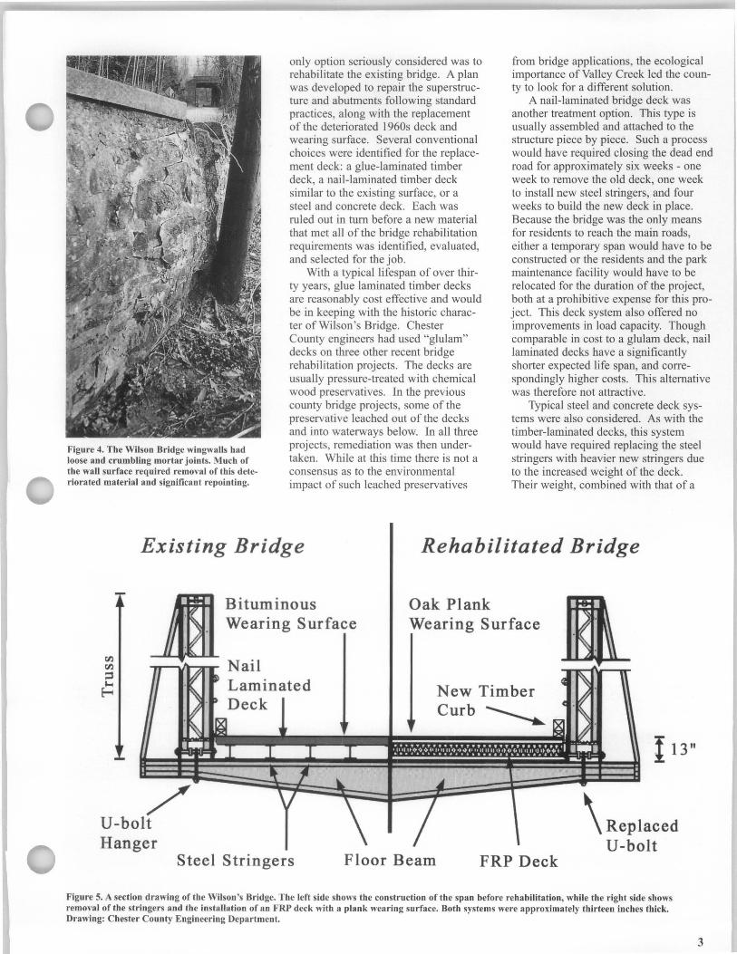
Figure 4. The Wilson Bridge wingwalls had loose and crumbling mortar joints. Much of the wall surface required removal of this deteriorated material and significant repointing.
only option seriously considered was to rehabilitate the existing bridge. A plan was developed to repair the superstructure and abutments following standard practices, along with the replacement of the deteriorated 1960s deck and wearing surface. Several conventional choices were identified for the replacement deck: a glue-laminated timber deck, a nail-laminated timber deck similar to the existing surface, or a steel and concrete deck. Each was ruled out in tum before a new material that met all of the bridge rehabilitation requirements was identified, evaluated, and selected for the job.
With a typical lifespan of over thirty years, glue laminated timber decks are reasonably cost effective and would be in keeping with the historic character of Wilson's Bridge. Chester County engineers had used "glulam" decks on three other recent bridge rehabilitation projects. The decks are usually pressure-treated with chemical wood preservatives. In the previous county bridge projects, some of the preservative leached out of the decks and into waterways below. In all three projects, remediation was then undertaken. While at this time there is not a consensus as to the environmental impact of such leached preservatives
from bridge applications, the ecological importance of Valley Creek led the county to look for a different solution.
A nail-laminated bridge deck was another treatment option. This type is usually assembled and attached to the structure piece by piece. Such a process would have required closing the dead end road for approximately six weeks - one week to remove the old deck, one week to install new steel stringers, and four weeks to build the new deck in place. Because the bridge was the only means for residents to reach the main roads, either a temporary span would have to be constructed or the residents and the park maintenance facility would have to be relocated for the duration of the project, both at a prohibitive expense for this project. This deck system also offered no improvements in load capacity. Though comparable in cost to a glulam deck, nail laminated decks have a significantly shorter expected life span, and correspondingly higher costs. This alternative was therefore not attractive.
Typical steel and concrete deck systems were also considered. As with the timber-laminated decks, this system would have required replacing the steel stringers with heavier new stringers due to the increased weight of the deck. Their weight, combined with that of a
Existing Bridge Rehabilitated Bridge
,/' U-bolt Hanger
Bituminous Wearing Surface
Oak Plank Wearing Surface
New Timber Curb~
Steel Stringers Floor Beam FRP Deck
I 13"
\ Replaced U-bolt
Figure 5. A section drawing of the Wilson 's Bridge. The left side shows the construction of the span before rehabilitation, while the right side shows removal of the stringers and the installation of an FRP deck with a plank wearing surface. Both systems were approximately thirteen inches thick. Drawing: Chester County Engineering Department.
3

new concrete deck, would have decreased the load capacity of the bridge to as little as three or four tons. Such a change would then require relocation of the park facility and make the passage of emergency vehicles and delivery of heating fuel to the residences virtually impossible. Because the load capacity would be reduced rather than increased, this alternative was also ruled out.
After most conventional solutions were assessed, Chester County engineers sought an alternative approach. Recent articles in technical publications and presentations at several conferences suggested the possible application of plastic composite decks for bridge rehabilitation work. The material is essentially a very high strength structural fiberglass commonly known as fiber reinforced polymer (FRP). Though in existence since the end of World War II, new technological developments have made its use in large structural sections such as bridge decks increasingly practical.
The characteristics of an FRP deck matched those sought by Chester County for Wilson's Bridge (see figure 5). Composite decks are chemically stable and resistant to deterioration caused by moisture, freeze-thaw cycles, chemicals and other forces that act on bridge surfaces. They also have a higher strength-to-weight ratio than conventional decks. This strength makes the use of steel stringers unnecessary. The reduced dead load of an FRP decked bridge allows a corresponding increase in the live loads the bridge is able to carry. Resins used in the FRP deck harden to a solid state so they can not leach or deteriorate, thus avoiding the release of any potentially harmful materials into the surrounding area, especially the creek below. Though the cost of a composite deck is somewhat higher than that of a naillaminated timber deck, the estimated life span of the former is more than twice as long. Additional cost savings are usually realized in the short construction times and low level of required maintenance.
The installation of a fiber reinforced polymer deck on Wilson's Bridge would be part of a thorough rehabilitation program. Repointing the masonry abutments and wing walls, replacing steel U-bolt hangers, and stripping and repainting the superstructure would be undertaken prior to the delivery of the composite deck.
4
Figure 6. Taken at the composite manufacturer, this photo shows layers of fiberglass arranged around the deck core and placed in the mold. The mold was then infused with a resin that sealed the layers into a one-piece panel. Photo: Hayati Catbas, Hardcore Composites.
Deck Fabrication The county worked with a manufacturer of fiber reinforced composites that had extensive experience in developing structural applications for the material. Using fiber-reinforced polymers, the company had fabricated a dozen traffic-bearing bridges or bridge decks in the previous four years, as well as numerous piers, pilings, and other marine structures. Plans were made for fabricating the deck at their facility in New Castle, Delaware, then ship-
ping it as a single panel to the Valley Creek site where it would be installed.
The manufacture of the FRP deck was made possible by a number of recent innovations in composite material production. The Wilson's Bridge deck was fabricated using a adaptation of the technique known as vacuum assisted resin transfer molding, or VARTM. In this technology, a plastic honeycomb core is sandwiched between fiber layers in a mold (see figure 6). The mold is sealed and a vacu-
Figure 7. After the panel had set into a solid mass, workers removed it from the mold and sanded and finished all surfaces. The last steps included painting the deck and installing the oak plank wearing surface. Photo: Hayati Catbas, Hardcore Composites.
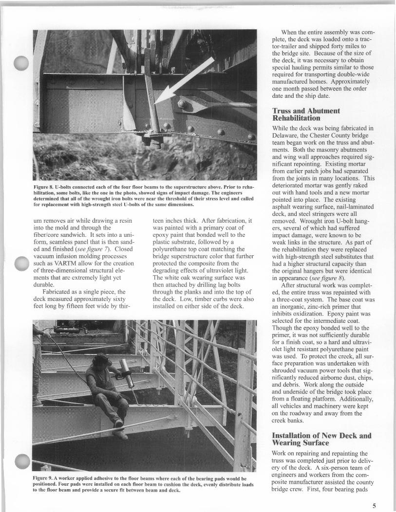
Figure 8. V-bolts connected each of the four floor beams to the superstructure above. Prior to rehabilitation, some bolts, like the one in the photo, showed signs of impact damage. The engineers determined that all of the wrought iron bolts were near the threshold of their stress level and called for replacement with high-strength steel V-bolts of the same dimensions.
urn removes air while drawing a resin into the mold and through the fiber/core sandwich. It sets into a uniform, seamless panel that is then sanded and finished (see figure 7). Closed vacuum infusion molding processes such as VARTM allow for the creation of three-dimensional structural elements that are extremely light yet durable.
Fabricated as a single piece, the deck measured approximately sixty feet long by fifteen feet wide by thir-
teen inches thick. After fabrication, it was painted with a primary coat of epoxy paint that bonded well to the plastic substrate, followed by a polyurethane top coat matching the bridge superstructure color that further protected the composite from the degrading effects of ultraviolet light. The white oak wearing surface was then attached by drilling lag bolts through the planks and into the top of the deck. Low, timber curbs were also installed on either side of the deck.
Figure 9. A worker applied adhesive to the floor beams where each of the bearing pads would be positioned. Four pads were installed on each floor beam to cushion the deck, evenly distribute loads to the floor beam and provide a secure fit between beam and deck.
When the entire assembly was complete, the deck was loaded onto a tractor-trailer and shipped forty miles to the bridge site. Because of the size of the deck, it was necessary to obtain special hauling permits similar to those required for transporting double-wide manufactured homes. Approximately one month passed between the order date and the ship date.
Truss and Abutment Rehabilitation While the deck was being fabricated in Delaware, the Chester County bridge team began work on the truss and abutments. Both the masonry abutments and wing wall approaches required significant repointing. Existing mortar from earlier patch jobs had separated from the joints in many locations. This deteriorated mortar was gently raked out with hand tools and a new mortar pointed into place. The existing asphalt wearing surface, nail-laminated deck, and steel stringers were all removed. Wrought iron U-bolt hangers, several of which had suffered impact damage, were known to be weak links in the structure. As part of the rehabilitation they were replaced with high-strength steel substitutes that had a higher structural capacity than the original hangers but were identical in appearance (see figure 8).
After structural work was completed, the entire truss was repainted with a three-coat system. The base coat was an inorganic, zinc-rich primer that inhibits oxidization. Epoxy paint was selected for the intermediate coat. Though the epoxy bonded well to the primer, it was not sufficiently durable for a finish coat, so a hard and ultraviolet light resistant polyurethane paint was used. To protect the creek, all surface preparation was undertaken with shrouded vacuum power tools that significantly reduced airborne dust, chips, and debris. Work along the outside and underside of the bridge took place from a floating platform. Additionally, all vehicles and machinery were kept on the roadway and away from the creek banks.
Installation of New Deck and Wearing Surface Work on repairing and repainting the truss was completed just prior to delivery of the deck. A six-person team of engineers and workers from the composite manufacturer assisted the county bridge crew. First, four bearing pads
5
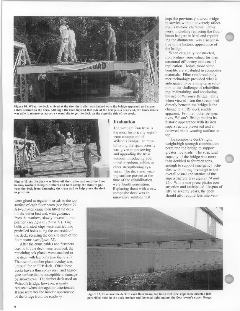
Figure 10. When the deck arrived at the site, the trailer was backed onto the bridge approach and crane cables secured to the deck. Although the road beyond that side of the bridge is a dead end, the truck driver was able to maneuver across a vacant site to get the deck on the opposite side of the creek.
Figure 11. As the deck was lifted off the trailer and onto the floor beams, workers wedged timbers and bars along the sides to prevent the deck from damaging the truss and to help place the deck in position.
were glued at regular intervals to the top surface of each floor beam (see figure 9). A twenty-ton crane then lifted the deck off the trailer bed and, with guidance from the workers, slowly lowered it into position (see figures 10 and 11). Lag bolts with steel clips were inserted into predrilled holes along the underside of the deck, securing the deck to each of the floor beams (see figure 12).
, Evaluation The wrought iron truss is the most historically significant component of Wilson's Bridge. In rehabilitating the span, priority was given to preserving and upgrading the truss without introducing additional members, cables or other strengthening systems. The deck and wearing surface present at the time of the rehabilitation were fourth generation. Replacing them with a new composite deck was an innovative solution that
kept the previously altered bridge in service without adversely affecting its historic character. Other work, including replacing the floorbeam hangers in kind and repointing the abutments, was also sensitive to the historic appearance of the bridge.
When originally constructed, iron bridges were valued for their structural efficiency and ease of replication. Today, those same benefits are attributed to composite materials. Fiber reinforced polymer technology provided what is anticipated to be a long-teml solution to the challenge of rehabilitating, maintaining, and continuing the use of Wilson's Bridge. Only when viewed from the stream bed directly beneath the bridge is the change to a FRP deck readily apparent. From all other perspectives, Wilson's Bridge retains its historic appearance with its iron superstructure preserved and a renewed plank wearing surface on top.
The composite deck's light weightlhigh strength combination permitted the bridge to support greater live loads. The structural capacity of the bridge was more than doubled to fourteen tons, enough to support emergency vehicles, with no major change to the overall visual appearance of the superstructure (see figures 14 and 15). With a one-piece plastic construction and anticipated lifespan of fifty to seventy years, the deck should also require less interven-
After the crane cables and fasteners used to lift the deck were removed, the remaining oak planks were attached to the deck with lag bolts (see figure 13). The use of a timber plank overlay was unusual for an FRP deck. Often these decks have a thin epoxy resin and aggregate surface that is susceptible to damage by snowplows. The timber deck used on Wilson's Bridge, however, is easily replaced when damaged or deteriorated. It also recreates the historic appearance of the bridge from the roadway.
Figure 12. To secure the deck to each floor beam, lag boIts with steel clips were inserted into predriUed holes in the deck surface and fastened tight against the floor beam's upper flange.
6
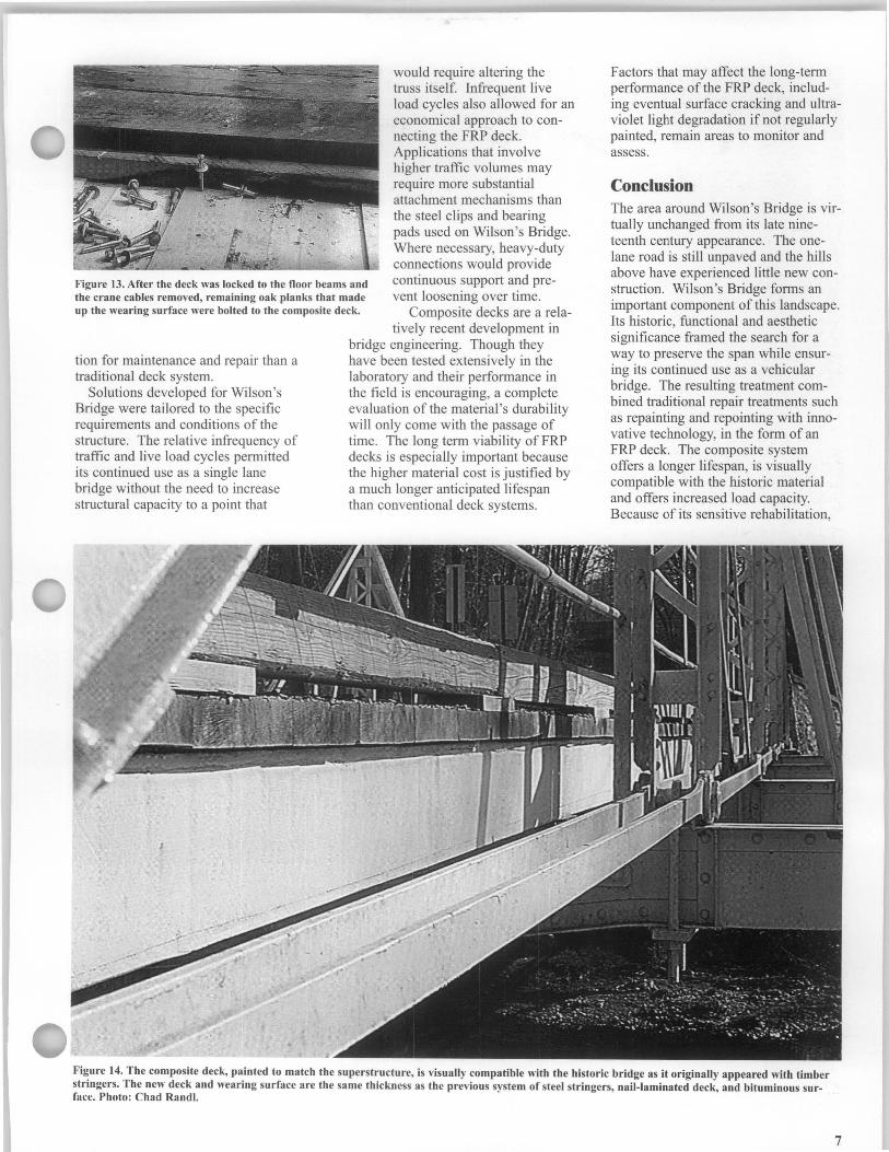
Figure 13. After the deck was locked to the floor beams and the crane cables removed, remaining oak planks that made up the wearing surface were bolted to the composite deck.
would require altering the truss itself. Infrequent live load cycles also allowed for an economical approach to connecting the FRP deck. Applications that involve higher traffic volumes may require more substantial attachment mechanisms than the steel clips and bearing pads used on Wilson's Bridge. Where necessary, heavy-duty connections would provide continuous support and prevent loosening over time.
Composite decks are a rela
tion for maintenance and repair than a traditional deck system.
Solutions developed for Wilson's Bridge were tailored to the specific requirements and conditions of the structure. The relative infrequency of traffic and live load cycles permitted its continued use as a single lane bridge without the need to increase structural capacity to a point that
tively recent development in bridge engineering. Though they have been tested extensively in the laboratory and their performance in the field is encouraging, a complete evaluation of the material's durability will only come with the passage of time. The long term viability of FRP decks is especially important because the higher material cost is justified by a much longer anticipated lifespan than conventional deck systems.
Factors that may affect the long-term performance of the FRP deck, including eventual surface cracking and ultraviolet light degradation if not regularly painted, remain areas to monitor and assess.
Conclusion The area around Wilson's Bridge is virtually unchanged from its late nineteenth century appearance. The onelane road is still unpaved and the hills above have experienced little new construction. Wilson's Bridge forms an important component of this landscape. Its historic, functional and aesthetic significance framed the search for a way to preserve the span while ensuring its continued use as a vehicular bridge. The resulting treatment combined traditional repair treatments such as repainting and repointing with innovative technology, in the form of an FRP deck. The composite system offers a longer lifespan, is visually compatible with the historic material and offers increased load capacity. Because of its sensitive rehabilitation,
Figure 14. The composite deck, painted to match the superstructure, is visually compatible with the historic bridge as it originally appeared with timber stringers. The new deck and wearing surface are the same thickness as the previous system of steel stringers, nail-laminated deck, and bituminous surface. Photo: Chad Randl.
7
Cost: The total cost of the Wilson's Bridge project including rehabilitating the truss and abutments and the price of the composite deck was approximately $40,000. The design and fabrication of the FRP deck came to $28,000 with another $2,000 for delivery and installation of the deck at Valley Creek. These figures reflected the close proximity of the composite manufacturer's facility to the bridge site as well as a modest discount offered by the manufacturer to encourage the use of FRP decks in historic bridge applications. The remaining $10,000 was attributed to truss and masonry work, including removing the deteriorated stringers, deck and wearing surface, replacing
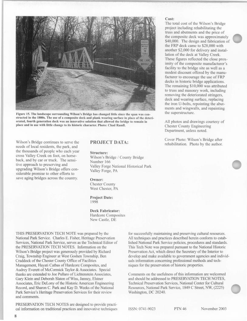
Figure 15. The landscape surrounding Wilson's Bridge has changed little since the span was constructed in the 1800s. The use of a composite deck and plank wearing surface in place of the deteriorated, fourth generation deck was an innovative solution that allowed the bridge to remain in place and in use with little change to its historic character. Photo: Chad Rand!.
the iron V-bolts, repointing the abutments and wingwalls, and repainting the superstructure.
All photos and drawings courtesy of Chester County Engineering Department, unless noted.
PROJECT DATA:
Structure:
Cover Photo: Wilson's Bridge after rehabilitation. Photo by the author. Wilson's Bridge continues to serve the
needs of local residents, the park, and the thousands of people who each year cross Valley Creek on foot, on horseback, and by car or truck. The sensitive approach to preserving and upgrading Wilson's Bridge offers considerable promise to other efforts to save aging bridges across the country.
Wilson's Bridge / County Bridge Number 166 Valley Forge National Historical Park Valley Forge, PA
Owner: Chester County West Chester, PA
Project Date: 1998
Deck Fabricator: Hardcore Composites New Castle, DE
THIS PRESERVATION TECH NOTE was prepared by the National Park Service. Charles E. Fisher, Heritage Preservation Services, National Park Service, serves as the Technical Editor of the PRESERVATION TECH NOTES. Information on the Wilson's Bridge project was generously provided by Richard Craig, Township Engineer at West Goshen Township, Ben Craddock of the Chester County Office of Facilities Management, Hayati Catbas of Hard core Composites, and Audrey Everett of McCormick Taylor & Associates. Special thanks are extended to Joe Pullaro of Lichtenstein Associates, Gary Klein and Deborah Slaton ofWiss, Janney, Elstner Associates, Eric DeLony of the Historic American Engineering Record, and Sharon C. Park and Kay D. Weeks of the National Park Service's Heritage Preservation Services for their review and comments.
PRESERVATION TECH NOTES are designed to provide practical information on traditional practices and innovative techniques
8
for successfully maintaining and preserving cultural resources. All techniques and practices described herein conform to established National Park Service policies, procedures and standards. This Tech Note was prepared pursuant to the National Historic Preservation Act, which direct the Secretary of the Interior to develop and make available to government agencies and individuals information concerning professional methods and techniques for the preservation of historic properties.
Comments on the usefulness of this information are welcomed and should be addressed to PRESERVATION TECH NOTES, Technical Preservation Services, National Center for Cultural Resources, National Park Service, 1849 C Street, NW, (2225) Washington, DC 20240.
ISSN: 0741-9023 PTN46 November 2003