Presentación de PowerPoint - CivilFEM
14
• “Only one software for all your Civil Engineering needs” SHRINKAGE CRACKING CONCRETE ANALYSIS OF FIBER REINFORCEMENT CONCRETE SLABS Courtesy of
Transcript of Presentación de PowerPoint - CivilFEM

• “Only one software for all your Civil Engineering needs”
SHRINKAGE CRACKING CONCRETE ANALYSIS OF FIBER REINFORCEMENT CONCRETE SLABS
Courtesy of
• “Only one software for all your Civil Engineering needs”
Description
This case study shows the results of the numerical study carried out on a fibre-reinforced concrete slab on a continuous support. The analysis focuses on the shrinkage behaviour of the concrete under different adherence conditions in the support layer (adherent and non-adherent). The analysis was carried out on a 10 m and 5m long slab with different thicknesses. A thermal analysis has also been carried out, taking into account the heat flow emitted by the concrete in the first days. In all cases, the stress state and deformations suffered by the slab were analyzed, as well as the existence or not of cracking.
• “Only one software for all your Civil Engineering needs”
Description
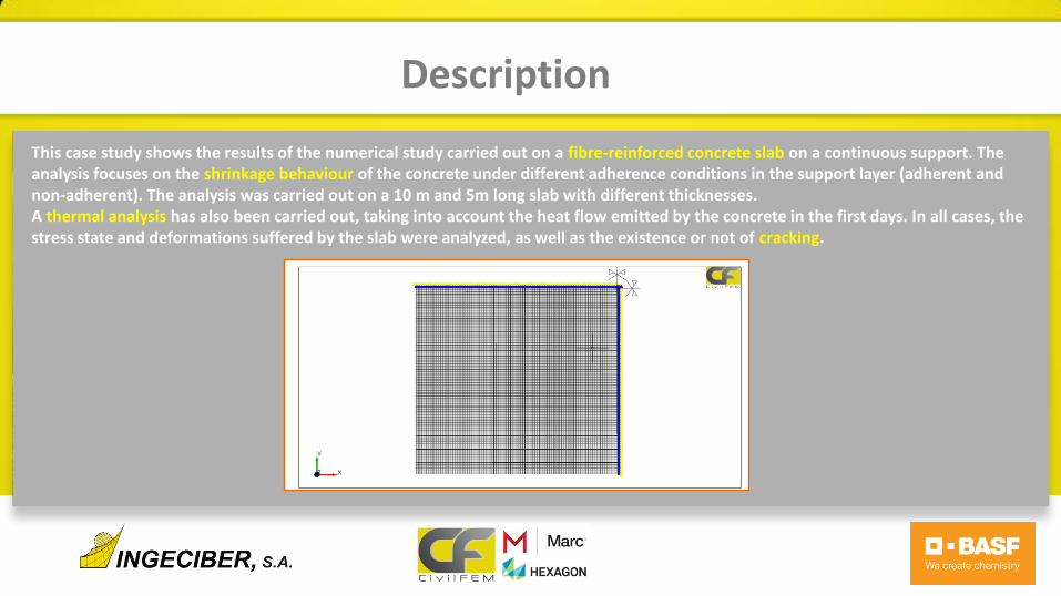
The cracking curve used in the CivilFEM powered by Marc finite element model , has been calibrated with the average test results shown in table 2-1. Below are the values of the post cracking stress-strain table and the graph with the results obtained in the test model made by the finite element method, in which the FRj value is related to the crack opening
• “Only one software for all your Civil Engineering needs”
Description
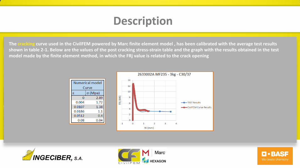
In this analysis, two shrinkage situations have been analyzed: variable, that is, with different humidity values (RH) at the top and bottom (case A), and constant or with uniform humidity (case B). The shrinkage values have been obtained from the Eurocode 2: Design of concrete structures. A notional size of 200mm and a class N cement have been considered. The values corresponding to the RH values 50 and 70% as a function of the age of the concrete are shown below.
• “Only one software for all your Civil Engineering needs”
Description
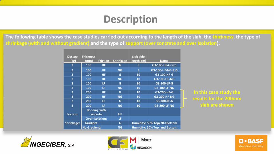
The following table shows the case studies carried out according to the length of the slab, the thickness, the type of shrinkage (with and without gradient) and the type of support (over concrete and over isolation).
Dosage (kg)
Thickness (mm) Friction Shrinkage
Slab side length (m) Name
3 100 HF G 5 G3-100-HF-G-5x5
3 100 HF NG 5 G3-100-HF-NG-5x5
3 100 HF G 10 G3-100-HF-G
3 100 HF NG 10 G3-100-HF-NG
3 100 LF G 10 G3-100-LF-G
3 100 LF NG 10 G3-100-LF-NG
3 200 HF G 10 G3-200-HF-G
3 200 HF NG 10 G3-200-HF-NG
3 200 LF G 10 G3-200-LF-G
3 200 LF NG 10 G3-200-LF-NG
Friction: Bonding with
concrete: HF
Over-isolation: LF
Shrinkage: Gradient: G Humidity: 50% Top/70%Bottom
No Gradient: NG Humidity: 50% Top and Bottom
In this case study the results for the 200mm
slab are shown
• “Only one software for all your Civil Engineering needs”
Results
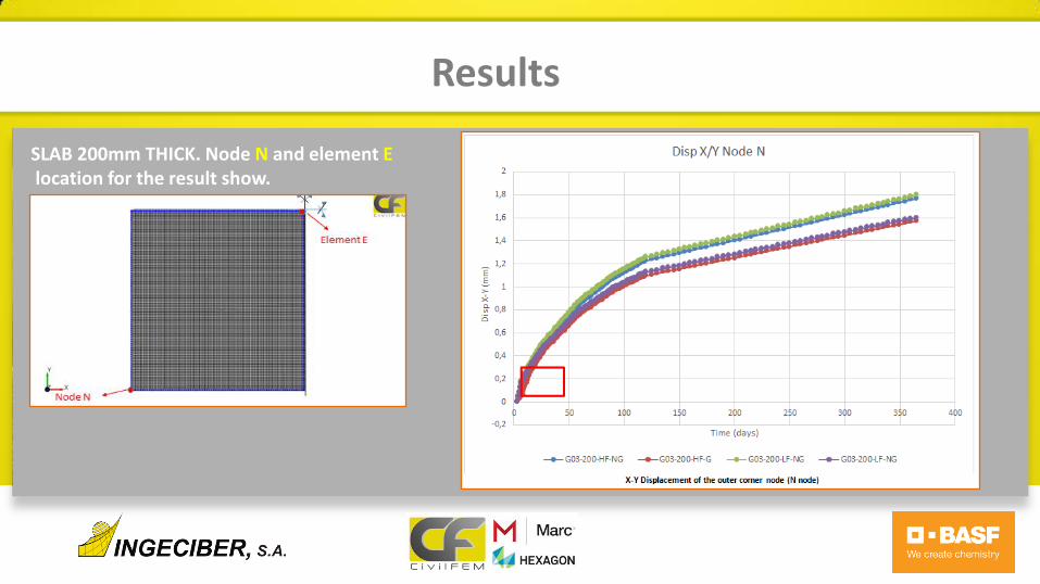
SLAB 200mm THICK. Node N and element E location for the result show.
• “Only one software for all your Civil Engineering needs”
Results

• “Only one software for all your Civil Engineering needs”
Results
• “Only one software for all your Civil Engineering needs”
Results
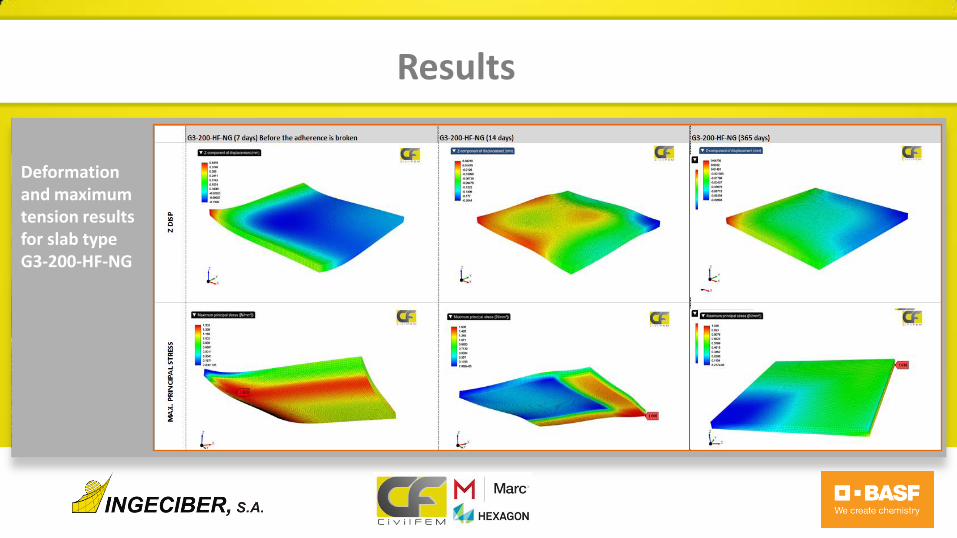
Deformation and maximum tension results for slab type G3-200-HF-NG
• “Only one software for all your Civil Engineering needs”
Results
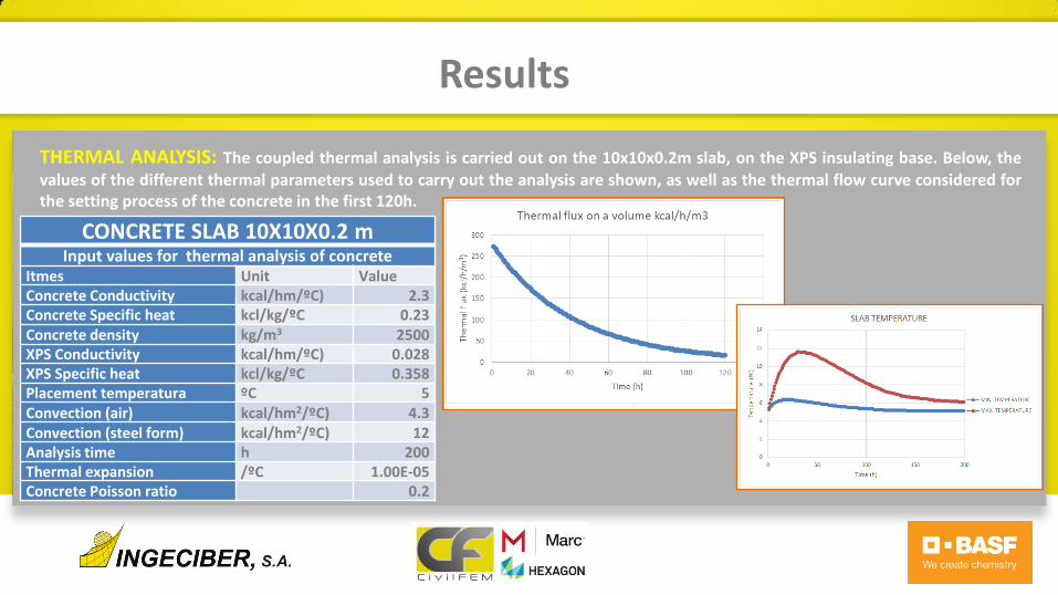
THERMAL ANALYSIS: The coupled thermal analysis is carried out on the 10x10x0.2m slab, on the XPS insulating base. Below, the values of the different thermal parameters used to carry out the analysis are shown, as well as the thermal flow curve considered for the setting process of the concrete in the first 120h.
CONCRETE SLAB 10X10X0.2 m Input values for thermal analysis of concrete
Itmes Unit Value Concrete Conductivity kcal/hm/ºC) 2.3 Concrete Specific heat kcl/kg/ºC 0.23 Concrete density kg/m3 2500 XPS Conductivity kcal/hm/ºC) 0.028 XPS Specific heat kcl/kg/ºC 0.358 Placement temperatura ºC 5 Convection (air) kcal/hm2/ºC) 4.3 Convection (steel form) kcal/hm2/ºC) 12 Analysis time h 200 Thermal expansion /ºC 1.00E-05 Concrete Poisson ratio 0.2
• “Only one software for all your Civil Engineering needs”
Results
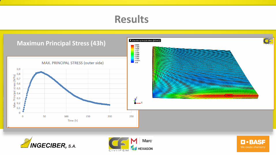
Maximun Principal Stress (43h)

• “Only one software for all your Civil Engineering needs”
Results
Minimun Principal Stress (43h)
• “Only one software for all your Civil Engineering needs”
Conclusion
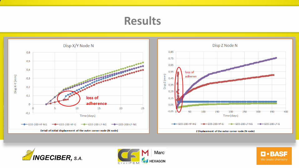
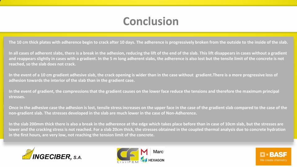
The 10 cm thick plates with adherence begin to crack after 10 days. The adherence is progressively broken from the outside to the inside of the slab. In all cases of adherent slabs, there is a break in the adhesion, reducing the lift of the end of the slab. This lift disappears in cases without a gradient and reappears slightly in cases with a gradient. In the 5 m long adherent slabs, the adherence is also lost but the tensile limit of the concrete is not reached, so the slab does not crack. In the event of a 10 cm gradient adhesive slab, the crack opening is wider than in the case without gradient.There is a more progressive loss of adhesion towards the interior of the slab than in the gradient case. In the event of gradient, the compressions that the gradient causes on the lower face reduce the tensions and therefore the maximum principal stresses. Once in the adhesive case the adhesion is lost, tensile stress increases on the upper face in the case of the gradient slab compared to the case of the non-gradient slab. The stresses developed in the slab are much lower in the case of Non-Adherence. In the slab 200mm thick there is also a break in the adherence at the edge which takes place before than in case of 10cm slab, but the stresses are lower and the cracking stress is not reached. For a slab 20cm thick, the stresses obtained in the coupled thermal analysis due to concrete hydration in the first hours, are very low, not reaching the tension limit of the concrete.

• “Only one software for all your Civil Engineering needs”
Courtesy of