Preliminary Project Execution Plan for the Heavy …videbaks/hft/cd1/PEP_draft.pdf1 Preliminary...
32
1 Preliminary Project Execution Plan for the Heavy Flavor Tracker Project (HFT) MIE – 01VB at Brookhaven National Laboratory Upton, NY For the U.S. Department of Energy Office of Science Office of Nuclear Physics (SC – 26) October 2009
-
Upload
hoangkhuong -
Category
Documents
-
view
217 -
download
0
Transcript of Preliminary Project Execution Plan for the Heavy …videbaks/hft/cd1/PEP_draft.pdf1 Preliminary...
1
Preliminary Project Execution Plan
for the Heavy Flavor Tracker Project
(HFT)
MIE – 01VB
at Brookhaven National Laboratory
Upton, NY
For the U.S. Department of Energy Office of Science
Office of Nuclear Physics (SC – 26)
October 2009

2
Project Execution Plan for the
Heavy Flavor Tracker Pre-Injector (HFT)
at Brookhaven National Laboratory CONCURRENCES: Flemming Videbaek Date HFT Contractor Project Manager Thomas Ludlam Date Chairman, Physics Department Brookhaven National Laboratory Steven Vigdor Date Associate Laboratory Director for Nuclear and Particle Physics Brookhaven National Laboratory Nand Narain Date HFT Federal Project Director DOE Brookhaven Site Office Michael D. Holland Date Manager DOE Brookhaven Site Office

3
Helmut Marsiske Date Program Manager for Nuclear Physics Instrumentation Office of Nuclear Physics, Office of Science _________________________________________ Date: _______________ Daniel R. Lehman Director Office of Project Assessment Office of Science APPROVED: Jehanne Gillo Date Director. Facilities and Project Management Division Office of Nuclear Physics Office of Science
4
TABLE OF CONTENTS 1 INTRODUCTION .................................................................................................... 6
2 MISSION NEED ....................................................................................................... 6 3 FUNCTIONAL REQUIREMENTS........................................................................ 7
3.1 POINTING RESOLUTION ..................................................................................... 8 3.2 MULTIPLE SCATTERING IN THE INNER LAYERS ............................................... 8 3.3 INTERNAL ALIGNMENT AND STABILITY ............................................................ 9 3.4 PXL INTEGRATION TIME................................................................................... 9 3.5 READ-OUT SPEED AND DEAD TIME ................................................................... 9 3.6 DETECTOR HIT EFFICIENCY.............................................................................. 9 3.7 HIGH FRACTION OF LIVE CHANNELS ....................................................... 10 3.8 SOFTWARE AND PROCEDURES READY ............................................................ 10
4 PROJECT OVERVIEW ........................................................................................ 10 4.1 R&D ................................................................................................................. 10 4.2 CONSTRUCTION ................................................................................................ 11
4.2.1 HFT Detector Overview........................................................................ 11 4.3 TECHNICAL SCOPE AND DELIVERABLES ......................................................... 13
5 MANAGEMENT ORGANIZATION ................................................................... 14
5.1 GENERAL........................................................................................................... 14 5.2 PROJECT MANAGEMENT RESPONSIBILITIES .................................................... 15
5.2.1 Department of Energy........................................................................... 15 5.2.2 Brookhaven National Laboratory ......................................................... 17 5.2.3 BNL Contractor Project Manager ........................................................ 17 5.2.4 Engineering Deputy .............................................................................. 18 5.2.5 Subsystem Managers............................................................................. 19 5.2.6 Quality Assurance Board...................................................................... 20 5.2.7 Project Integrator(s) ............................................................................. 20
5.3 INTEGRATED PROJECT TEAM ........................................................................... 21 5.4 PARTICIPATING INSTITUTIONS ........................................................................ 21 5.5 OPERATION PHASE ........................................................................................... 22 5.6 LIFE CYCLE COSTS............................................................................................ 22
6 SCHEDULE AND COST RANGE ....................................................................... 22
6.1 SCHEDULE......................................................................................................... 23 6.2 MILESTONES..................................................................................................... 23 6.3 COST SCOPE....................................................................................................... 25
6.3.1 Funding ................................................................................................. 26 6.3.2 Contingency .......................................................................................... 27
7 CHANGE CONTROL............................................................................................ 27
8 ANALYSES, ASSESSMENTS AND PLANS....................................................... 28 8.1 ENVIRONMENT, SAFETY AND HEALTH ............................................................ 28
8.1.1 Purpose of the ESSH Chapter............................................................... 28
flemming videbaek � 10/24/09 12:22 PMDeleted: 10

5
8.1 ENVIRONMENTAL, SAFETY AND HEALTH........................................................ 29 8.1.1 Integrated Safety Management ............................................................. 29 8.1.2 NEPA..................................................................................................... 29 8.1.3 ESSH Plans for Construction ............................................................... 29
8.2 PROJECT QUALITY ASSURANCE PROGRAM .................................................... 30 8.2.1 Program ................................................................................................ 30 8.2.2 Documents and Records ....................................................................... 30 8.2.3 Work Process ........................................................................................ 30
9 PROJECT CONTROLS AND REPORTING SYSTEMS.................................. 31 9.1 VALUE ENGINEERING....................................................................................... 32
GLOSSARY .....................................................ERROR! BOOKMARK NOT DEFINED.
flemming videbaek � 10/24/09 12:22 PMDeleted: 33
6
1 INTRODUCTION Brookhaven National Laboratory (BNL), located in Upton, NY, is owned by the U.S. Department of Energy (DOE) and operated by Brookhaven Science Associates (BSA) under the U.S. Department of Energy Contract No. DE-AC02-98CH10886. The flagship Nuclear Physics facility at BNL is the Relativistic Heavy Ion Collider (RHIC). Two detectors,
CD-0 Approve Mission Need: Authority – Director, Office of Science (Acting) On February 18, 2009 Eugene A. Henry approved the statement of Mission Need for the STAR Heavy Flavor Tracker with a Total Project Cost (TPC) range of $11-$15 million. This Project Execution Plan (PEP) describes the coordination of efforts of the project team, including the processes and procedures used by the HFT Contractor Project Manager (CPM) and Federal Project Director (FPD) to ensure that the project is completed on time and within budget. The PEP defines the project scope and the organizational framework, identifies roles and responsibilities of contributors, and presents the work breakdown structure (WBS) and schedule. The PEP also describes the formal change control process by which project cost, schedule, or scope may be revised in consultation with the FPD and the DOE Office of Science, Office of Nuclear Physics.
2 MISSION NEED The mission of the Nuclear Physics (NP) program is to understand the evolution and structure of nuclear matter from the smallest building blocks, quarks and gluons, to the elements in the universe created by stars. A main objective of this nuclear science field is searching for and characterizing the properties of the QGP that might occur in extremely hot, dense plasma of quarks and gluons believed to have filled the universe about a millionth of a second after the “Big Bang.” The program provides world-class peer-reviewed research results in the scientific disciplines encompassed by the Nuclear Physics mission areas under the mandate provided in Public Law 95-91 that established the Department.
The HFT project directly supports the NP mission and will allow U.S. researchers to explore fundamental questions into the nature of the QGP which cannot be examined with any other experimental facility worldwide.
The primary motivation for the HFT is to extend STAR’s capability to measure heavy flavor production by the measurement of displaced vertices and to do the direct topological identification of open charm hadrons. These are key measurements for the heavy-ion program at RHIC. Heavy quark measurements will facilitate the heavy-ion program as it moves from the discovery phase to the systematic characterization of the dense medium created in heavy-ion collisions. The primary physics topics to be addressed by the HFT include heavy flavor energy loss, flow, and a test of partonic
mirabella � 10/22/09 10:30 AMComment: Need some words here
7
thermalization at RHIC. Without the HFT upgrade the STAR experiment will not be able to execute the comprehensive heavy flavor program proposed here. This program has been identified as a key goal for the RHIC program in the Long Range Plan RHIC-II science program and in the RHIC mid-term scientific plan.
3 FUNCTIONAL REQUIREMENTS The technical objectives of the Heavy Flavor Tracker need to meet requirements of both the RHIC and STAR experimental long term programs. The corresponding technical scope and performance specifications required at Critical Decision-4 (CD-4) are described in this section. STARD was designed to make measurements of hadron production over a large solid angle, and it features detector systems for high precision tracking, momentum analysis and particle identification. It is the only experiment at RHIC which measures the full azimuth in φ and tracks particles from 100 MeV/c to 20 GeV/c. Therefore, it is well suited for both characterization of heavy-ion collisions event-by-event and also to investigate large Q2 effects.
By adding a Heavy Flavor Tracker (HFT) to STAR, we will be able to measure neutral and charged particles with displaced vertices that decay 100 µm, or less, from the primary vertex. The high spatial resolution of the tracker will allow us to study parent particles with a very short lifetime from decay of heavy quarks, such as the D0 meson. The addition of the HFT will extend STAR’s unique capabilities even further by providing direct topological identification of mesons and baryons containing charm, and for non-photonic electrons decaying from charm and bottom hadrons, and by bottom semi-leptonic decays. Thus, the HFT is the enabling technology for making direct charm and bottom measurements in STAR.
The Heavy Flavor Tracker consists of two new sub-detectors: a silicon pixel detector (PXL) and an intermediate silicon tracker (IST), and the Silicon Strip Detector (SSD). The SSD is an existing detector that will have its readout system upgraded to match the requirements of the overall STAR Data Acquisition system The primary purpose of the SSD-IST-PXL detector is to provide graded resolution from the TPC into the interaction point and to provide excellent pointing resolution at the interaction point for resolving secondary particles and displaced decay vertices. The TPC will point at the SSD with a resolution of about 1 mm, the SSD will point at the IST with a resolution of about 300 µm, the IST will point at the PXL with a resolution of about 200 µm, and the PXL detector will point at the vertex with 50 µm resolution. This detector system will be supported by a new global support structure that will be integrated with ongoing upgrade to the STAR detector.
8
The HFT detector identifies the decay vertex of mesons and baryons containing heavy mass quarks like for example, the D0 or the ΛC, by reconstructing the trajectory of its charged daughter tracks. The decays have a unique topology that is easy to identify. The following selection criteria can be used to separate e.g. the D0 signal from background tracks:
• The distance of closest approach DCA between the daughter tracks and the primary vertex
• Isolation cuts on cos(θ), with θ being the angle between the D0 momentum (vector sum of the two daughter momenta) and the vector joining the primary vertex to the D-meson decay vertex
• The distance of closest approach between the two daughter tracks • The difference, Δm, between the reconstructed invariant mass and the D0 rest
mass
The performance requirements listed below are selected so that if the detector meets those requirements, the detector will be able to achieve the physics requirements. Fulfillment of the performance requirements can be completely determined shortly after the installation of the HFT.
3.1 POINTING RESOLUTION Heavy flavor hadrons have extremely short life times (cτ ~ 50 µm). Identifying such a short displaced vertex requires extremely good pointing resolution. This is especially important for the identification of low transverse momentum decays where small gains in pointing resolution lead to large gains in detection efficiency. We require a pointing resolution of better than 50 µm for kaons of 750 MeV/c. 750 MeV/c is the mean momentum of the decay kaons from D mesons of 1 GeV/c transverse momentum, the peak of the D meson distribution. The pointing resolution that will be achieved by the HFT can be calculated from the design parameters and from survey of the sensor ladders.
3.2 MULTIPLE SCATTERING IN THE INNER LAYERS The precision with which we can point to the interaction vertex is determined by the position resolution of the PXL detector layers and by the effects of multiple scattering in the material the particles have to traverse. The beam pipe and the first PXL layer are the two elements that have the most adverse effect on pointing resolution. Therefore, it is crucial to make those layers as thin as possible and to build them as close as possible to the interaction point. We have chosen a radius of 2 cm for a new beam pipe. Making this radius even smaller would make the STAR beam pipe the limiting aperture of the RHIC ring. This is not a desirable situation. The central section of the beam pipe will be fabricated from Beryllium. Such a beam pipe can have a minimal wall thickness of 750 µm, equivalent to 0.21 % of a radiation length.
9
The two PXL layers will be at a radius of 2.5 cm and 8 cm, respectively. The sensors will be thinned down to 50 µm and the ladders will be fabricated in ultra-light carbon fibre technology. The total thickness of the first PXL layer will be the equivalent of 0.4 % of a radiation length. With those parameters, the contributions to the pointing resolution from multiple scattering and from detector resolution will be about equal. The radiation lengths of the two innermost structures, the beam pipe and the first PXL layer, are design parameters.
3.3 INTERNAL ALIGNMENT AND STABILITY
The PXL and the IST positions need to be known and need to be stable over a long time period in order not to have a negative effect on the pointing resolution. The quality of the data will depend on alignment and long term stability. This is especially important for the PXL detector that needs to be installed and removed on a short time scale. The alignment and stability need to be better than 300 µm for the IST and better than 20 µm for the PXL. Those parameters can be determined from a survey.
3.4 PXL INTEGRATION TIME
Compared to the strip detectors, the PXL is a slow device with a long integration time. All events that occur during the integration or life time of the PXL will be recorded. This makes assigning PXL hits to a particular track in the TPC a difficult pattern recognition problem. From detailed simulations we have concluded that at RHIC II luminosities the detection and reconstruction efficiency for D-mesons is not appreciably degraded due to multiple events and tracks in the PXL if the integration time of the detector is smaller than 200 µs. The PXL integration time is a design parameter.
3.5 READ-OUT SPEED AND DEAD TIME
In the absence of a good trigger for D-mesons it is imperative for the measurement of rare processes to record as many events as possible and as required by the physics processes. In STAR the speed of the DAQ is the limiting factor for the number of events recorded. In order not to slow down the STAR DAQ, the HFT read-out speed needs to be compatible with the STAR DAQ speed and the HFT needs to be dead time free. Read-out speed and dead time are design parameters.
3.6 DETECTOR HIT EFFICIENCY
The hit efficiency of PXL and IST detectors is essential for good detection efficiency. In the case of secondary decay reconstruction, the hit inefficiency of each detector layer
10
enters with the power of the number of reconstructed decay particles into the total inefficiency. In order to keep inefficiency low, we request that each individual detector layer has a hit efficiency of better than 95%. The hit efficiency of each detector layer can be measured on the bench before installation.
3.7 HIGH FRACTION OF LIVE CHANNELS
Dead channels in the PXL and IST will cause missing hits on tracks and thus lead to inefficiencies in the reconstruction of decay tracks. Therefore, the number of dead channels needs to be as low as possible. The impact of dead channels on the overall performance will be minimal if more than 97% of all channels are alive at any time. The number of dead channels can be determined immediately after installation of the detectors.
3.8 SOFTWARE AND PROCEDURES READY
Analysis, Alignment, and Calibration procedures and software are necessary for the ability to analyze data and to extract physics information. The detector performance can only be realized if software and procedures are in place and fully functional. Software and procedures are ready when test data or simulated data can be processed through the official STAR analysis chain.
4 PROJECT OVERVIEW The technical activities within the MIE project may be divided into several main areas reflected in the WBS structure: (1) Management (2) Pixel Detector fabrication, integration and test and (3) IST Detector fabrication, integration and test (4) Silicon Strip Detector (SSD) , (5) Integration A substantial program of pre-conceptual R&D has been completed prior to CD-0 and R&D has continued through the interval between CD-0 and CD-1.
4.1 R&D A substantial program of pre-conceptual R&D has been completed prior to CD-0 and R&D will continue through the interval between CD-0 and CD-1.
The objective of the R&D for the PXL detector is to explore Si detector technology options and study detector performance for these technology alternatives. Prior to CD-0, several generations of active pixel sensors (APS) were designed and built at IRES/Strasbourg and the final chip for the PXL detector is now in development, based on
flemming videbaek � 10/22/09 10:30 AMComment: Should probably go due to R&D not in plan.
11
the experience gained with these early chips. There are several short term R&D projects to explore the mechanical and thermal stability requirements for the PXL detector and to learn how to implement such a high resolution detector.
The R&D items for the IST are to build a prototype ladder with sensors that can be integrated with STAR. These studies will show how to stabilize the proposed mechanical support structures, validate the quality of the readout system and then prove the effectiveness of the air cooling system for the chips. In addition the construction of a prototype ladder for the IST will exercise the assembly procedures and help us develop and refine the techniques to be used in the construction phase.
4.2 CONSTRUCTION In the following sections, the major systems and activities in the construction phase of the project are summarized.
4.2.1 HFT Detector Overview The PXL detector is a low mass detector that will be located very close to the beam pipe. It will be built with two layers of silicon pixel detectors: one layer at 2.5 cm average radius and the other at 8.0 cm average radius. The outer layer will have 30 ladders and the inner layer will have 10 ladders; for a total of 40. Each ladder contains a row of 10 monolithic CMOS detector chips and each ladder has an active area of 19.2 cm × 1.92 cm. The CMOS chips contain a 640 × 640 array of 18 µm square pixels and will be thinned down to a thickness of 50 µm to minimize Multiple Coulomb Scattering (MCS) in the detector. The effective thickness of each ladder is ~0.37% of a radiation length.
The IST is a strip detector that is designed to match the high resolution of the PXL detector with the coarser resolution of the TPC and the SSD. The IST sits inside the SSD. In order to provide the required graded resolution between the SSD and the PIXEL layers, a high rate conventional silicon barrel layers will be installed at radii of 14 cm. The IST layers provide space-points in the z and r-φ directions thereby reducing the number of possible candidate tracks that can be connected with hits on the outer layer of the PXL detector.
The SSD detector is an existing double-sided silicon strip detector, that operated inside STAR during 2003-2007. The detector provides redundancy and higher efficiency for the overall HFT system. The detector electronics will be upgraded in this project to match the requirements of the STAR Data acquisition System readout speed.
The 3 detector sub-systems PXL, IST and SSD, as well a a new thin walled, and small diameter beam pipe will be supported by the Inner Detector Support (IDS) structure
12
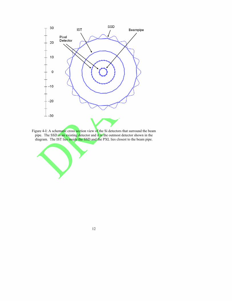
Figure 4-I: A schematic cross section view of the Si detectors that surround the beam
pipe. The SSD is an existing detector and it is the outmost detector shown in the diagram. The IST lies inside the SSD and the PXL lies closest to the beam pipe.
13
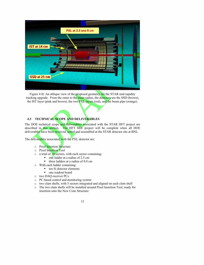
Figure 4-II: An oblique view of the proposed geometry for the STAR mid-rapidity
tracking upgrade. From the outer to the inner radius, the detectors are the SSD (brown), the IST layer (pink and brown), the two PXL layers (red), and the beam pipe (orange).
4.3 TECHNICAL SCOPE AND DELIVERABLES The DOE technical scope and deliverables associated with the STAR HFT project are described in this section. The HFT MIE project will be complete when all DOE deliverables have been received, tested and assembled at the STAR detector site at BNL.
The deliverables associated with the PXL detector are:
o Pixel Insertion Structure o Pixel Insertion Tool o a total of 10 sectors, with each sector containing:
one ladder at a radius of 2.5 cm three ladders at a radius of 8.0 cm
o With each ladder containing: ten Si detector elements one readout board
o two DAQ receiver PCs o PC based control and monitoring system o two clam shells, with 5 sectors integrated and aligned on each clam shell o The two clam shells will be installed around Pixel Insertion Tool, ready for
insertion onto the New Cone Structure

14
o One additional complete detector and sufficient sector and populated ladder components to have the capability to fabricate one more complete detector assemblies
o Provide services including cabling and cooling
The deliverables associated with the IST are:
• 27 ladders (24 + 3 spares) with 6 sensors per ladder • Readout system for 24 ladders • Silicon bias voltage system for 24 ladders • 24 IST ladders installed on the Middle Support Cylinder. • Provide services including cabling and cooling
The deliverables associated with the SSD are:
• Instrument 20 of the existing SSD ladders with new readout electronics compatible with the readout requirements for the TPC
• SSD installed on the Outer Support Cylinder • Provide services including cabling and cooling compatible with the IDS and FGT
The deliverable associated with the IDS are:
• The east support cone, and the middle support cylinders for the SSD, IST and the beam pipe support
The deliverable for the software are:
• Calibration and Monitoring software including Alignment and Distortions correction packages plus proper Databases of the detector state during data taking.
• Event reconstruction software fully integrated with the STAR software framework. This includes Hit and Track reconstruction software, Event and secondary vertex finder software
• Simulation and Evaluation software. This includes proper geometry databases, detector response packages, track embedding, association and evaluation.
• Physics analysis software fully integrated with the STAR software framework.
5 MANAGEMENT ORGANIZATION
5.1 GENERAL
This document provides the management organization for the HFT as defined for the development, construction and final assembly. Agreements between BNL and LBNL were established and will be documented by a Memorandum of
15
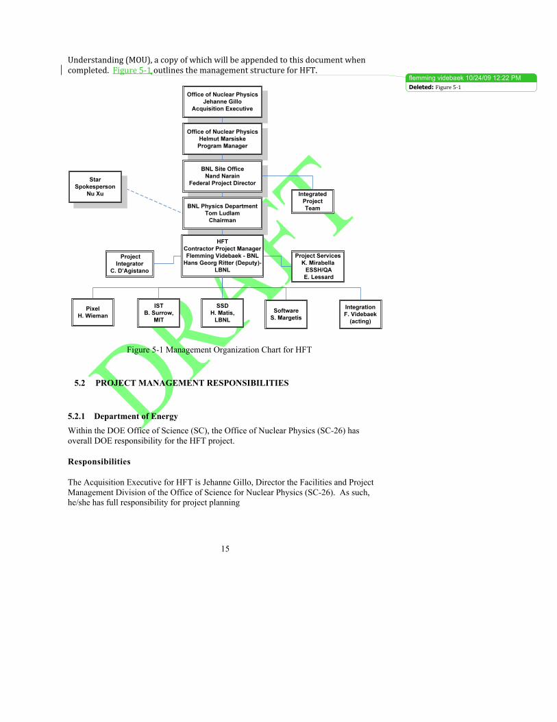
Understanding (MOU), a copy of which will be appended to this document when completed. Figure 5‐1 outlines the management structure for HFT.
Figure 5-1 Management Organization Chart for HFT
5.2 PROJECT MANAGEMENT RESPONSIBILITIES
5.2.1 Department of Energy Within the DOE Office of Science (SC), the Office of Nuclear Physics (SC-26) has overall DOE responsibility for the HFT project. Responsibilities The Acquisition Executive for HFT is Jehanne Gillo, Director the Facilities and Project Management Division of the Office of Science for Nuclear Physics (SC-26). As such, he/she has full responsibility for project planning
flemming videbaek � 10/24/09 12:22 PMDeleted: Figure 5‐1
16
and execution, and for establishing broad policies and requirements for achieving project goals. Specific responsibilities for the HFT project include:
• Chairs the ESAAB Equivalent Board. • Approves Critical Decisions and Level 1 baseline changes. • Approves the Project Execution Plan. • Delegates approval authority for Level 2 baseline changes to the Federal Project
Director. • Conducts Quarterly Project Reviews. • Ensures independent project reviews are conducted.
The Office of Nuclear Physics (SC-26.2) is responsible for planning, constructing, and operating user facilities to provide special scientific and research capabilities to serve the needs of U.S. universities, industry, and private and Federal laboratories. Within NP, the Facilities and Project Management Division (SC-26.2) has direct responsibility for providing funding, and programmatic guidance to the HFT project. The HFT Program Manager, in SC-26.2, is the primary point of contact with the following responsibilities:
• Oversees development of project definition, scope and budget. • Prepares, defends, and provides project budget with support from the field
organizations. • Reviews and provides recommendations to the AE on Level 1 baseline changes. • Monitors Level 1 and 2 technical, cost, and schedule milestones. • Participates in Quarterly Reviews, ESAAB Equivalent Board meetings, and
project reviews. • Ensures ES&H requirements are implemented by the project. • Coordinates with other SC Staff offices, HQ program offices and the DOE Office
of Engineering and Construction Management (OECM). Helmut Marsiske is the Federal HFT Program Manager.
Nand Narain at the Brookhaven Site Office (BHSO) is assigned as the Federal Project Director. The Federal Project Director responsibilities include:
• Overall responsibility for planning, implementing, and completing HFT. • Provides overall project management oversight. • Issues key work authorization. • Provides necessary funds via approved financial plans. • Manages and allocates the contingency funds according to the procedure defined
in the Baseline Change Control (Section 7). • Submits key project documents and critical decisions to DOE and reports project
progress. • Ensures that the project complies with applicable ES&H requirements (e.g.,
National Environmental Policy Act [NEPA] requirements). • Approves Level 2 Baseline changes.
17
5.2.2 Brookhaven National Laboratory Chairman for the Physics Department at BNL Funding for this project will be directed through BNL’s Physics Department. Fiscal and management responsibility for the fabrication of HFT will reside with the Chairman, Thomas Ludlam. Responsibilities The Chairman for the Physics Department at BNL shall be administratively and fiscally responsible for the entire project. In particular he must do the following:
• Provides overall management oversight for all aspects of the project. • Appoints the Contractor Project Manager. • Approves key personnel appointments made by the Contractor Project Manager. • Approves major subcontracts recommended by the Contractor Project Manager. • Ensures that adequate staff and resources are available to complete HFT in a
timely and cost effective manner (within constraints of the budget provided by DOE).
• Ensures that HFT has demonstrated that it meets the functional requirements. • Provides documentation and access to information necessary for operation of HFT
at other sites. • Ensures the work is performed safely and in compliance with the ISM rules. • Reports to the Associate Laboratory Director for Nuclear and Particle Physics
regarding the operations of the Physics Department.
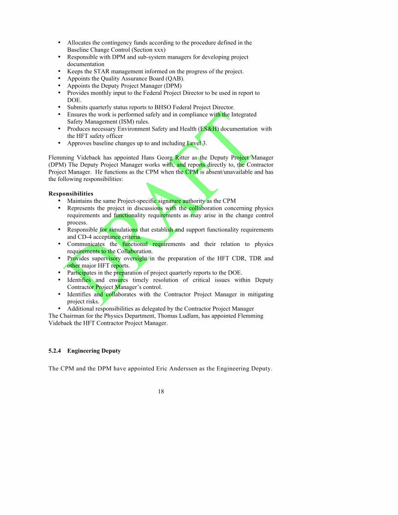
5.2.3 BNL Contractor Project Manager The Chairman for the Physics Department, Thomas Ludlam, has appointed Flemming Videbaek the HFT Contractor Project Manager. Responsibilities The Contractor Project Manager (CPM) shall report directly to the Chairman for the Physics Department and will be in charge of the overall management of HFT. The CPM shall appoint the key staff needed for the project with the approval of the Chairman for the Physics Department. The CPM also will have the following responsibilities:
• Responsible and accountable for the successful execution of contractor’s project scope of HFT.
• Supports FPD in implementing DOE project management process. • Delivers project deliverables as defined in this PEP. • Identifies and ensures timely resolution of critical issues within contractor’s
control.
18
• Allocates the contingency funds according to the procedure defined in the Baseline Change Control (Section xxx)
• Responsible with DPM and sub-system managers for developing project documentation
• Keeps the STAR management informed on the progress of the project. • Appoints the Quality Assurance Board (QAB). • Appoints the Deputy Project Manager (DPM) • Provides monthly input to the Federal Project Director to be used in report to
DOE. • Submits quarterly status reports to BHSO Federal Project Director. • Ensures the work is performed safely and in compliance with the Integrated
Safety Management (ISM) rules. • Produces necessary Environment Safety and Health (ES&H) documentation with
the HFT safety officer • Approves baseline changes up to and including Level 3.
Flemming Videbaek has appointed Hans Georg Ritter as the Deputy Project Manager (DPM) The Deputy Project Manager works with, and reports directly to, the Contractor Project Manager. He functions as the CPM when the CPM is absent/unavailable and has the following responsibilities: Responsibilities
• Maintains the same Project-specific signature authority as the CPM • Represents the project in discussions with the collaboration concerning physics
requirements and functionality requirements as may arise in the change control process.
• Responsible for simulations that establish and support functionality requirements and CD-4 acceptance criteria.
• Communicates the functional requirements and their relation to physics requirements to the Collaboration.
• Provides supervisory oversight in the preparation of the HFT CDR, TDR and other major HFT reports.
• Participates in the preparation of project quarterly reports to the DOE. • Identifies and ensures timely resolution of critical issues within Deputy
Contractor Project Manager’s control. • Identifies and collaborates with the Contractor Project Manager in mitigating
project risks. • Additional responsibilities as delegated by the Contractor Project Manager
The Chairman for the Physics Department, Thomas Ludlam, has appointed Flemming Videbaek the HFT Contractor Project Manager.
5.2.4 Engineering Deputy The CPM and the DPM have appointed Eric Anderssen as the Engineering Deputy.

19
Responsibilities
.
• Responsible for the development of the HFT system design requirements, including interfaces between subsystems, and methods and practices for achieving these requirements.
• Controls changes in the HFT system design requirements, including interfaces between subsystems.
• Responsible for overall engineering safety of project design • Identifies and ensures timely resolution of critical issues within Deputy Contractor
Project Manager’s control. • Identifies project risks and collaborates with the Contractor Project Manager in
mitigating project risks. • Additional responsibilities as delegated by the Contractor Project Manager.
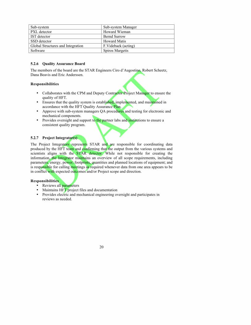
5.2.5 Subsystem Managers The HFT Project contains three major systems: Pixel detector, IST detector, and SSD detector. In addition there are managers for Software and for Integration. The HFT Contractor Project Manager has appointed managers to be responsible for the subsystems, which comprise the major systems. They will be responsible for the design, construction, installation, and testing of their subsystem, in accordance with the performance requirements, schedule, and budget. Responsibilities
• Assemble the staff and resources needed to complete the subsystem in collaboration with CPM and DPM
• Communicate the system design requirements to the staff. • Ensure that subsystems meet the HFT system design requirements, including
interfaces. • Responsible for carrying out the design, construction and assembly of the
subsystem in accordance with the scope, schedule and budget, assuming funding and resources as described in the PEP.
• Provide monthly reports on the status of the subsystem to the Contractor Project Manager.
• Responsible with the project and deputy project managers for providing documentation and presentations for reviews
• Develop and maintain the documentation of the subsystem (provide documentation to integrator)
• Ensure the work is performed safely and in compliance with the safety applicable to the respective institutions.
20
Sub-system Sub-system Manager PXL detector Howard Wieman IST detector Bernd Surrow SSD detector Howard Matis Global Structures and Integration F.Videbaek (acting) Software Spiros Margetis
5.2.6 Quality Assurance Board The members of the board are the STAR Engineers Ciro d’Augostino, Robert Scheetz, Dana Beavis and Eric Anderssen. Responsibilities
• Collaborates with the CPM and Deputy Contractor Project Manager to ensure the
quality of HFT. • Ensures that the quality system is established, implemented, and maintained in
accordance with the HFT Quality Assurance Plan. • Approve with sub-system managers QA procedures and testing for electronic and
mechanical components. • Provides oversight and support to the partner labs and institutions to ensure a
consistent quality program.
5.2.7 Project Integrator(s) The Project Integrators represents STAR and are responsible for coordinating data produced by the HFT team and confirming that the output from the various systems and scientists aligns with the STAR detector. While not responsible for creating the information, the Integrator maintains an overview of all scope requirements, including parameters, energy, power; footprints, quantities and planned locations of equipment; and is responsible for calling meetings as required whenever data from one area appears to be in conflict with expected outcomes and/or Project scope and direction. Responsibilities
• Reviews all parameters • Maintains HFT project files and documentation • Provides electric and mechanical engineering oversight and participates in
reviews as needed.
21
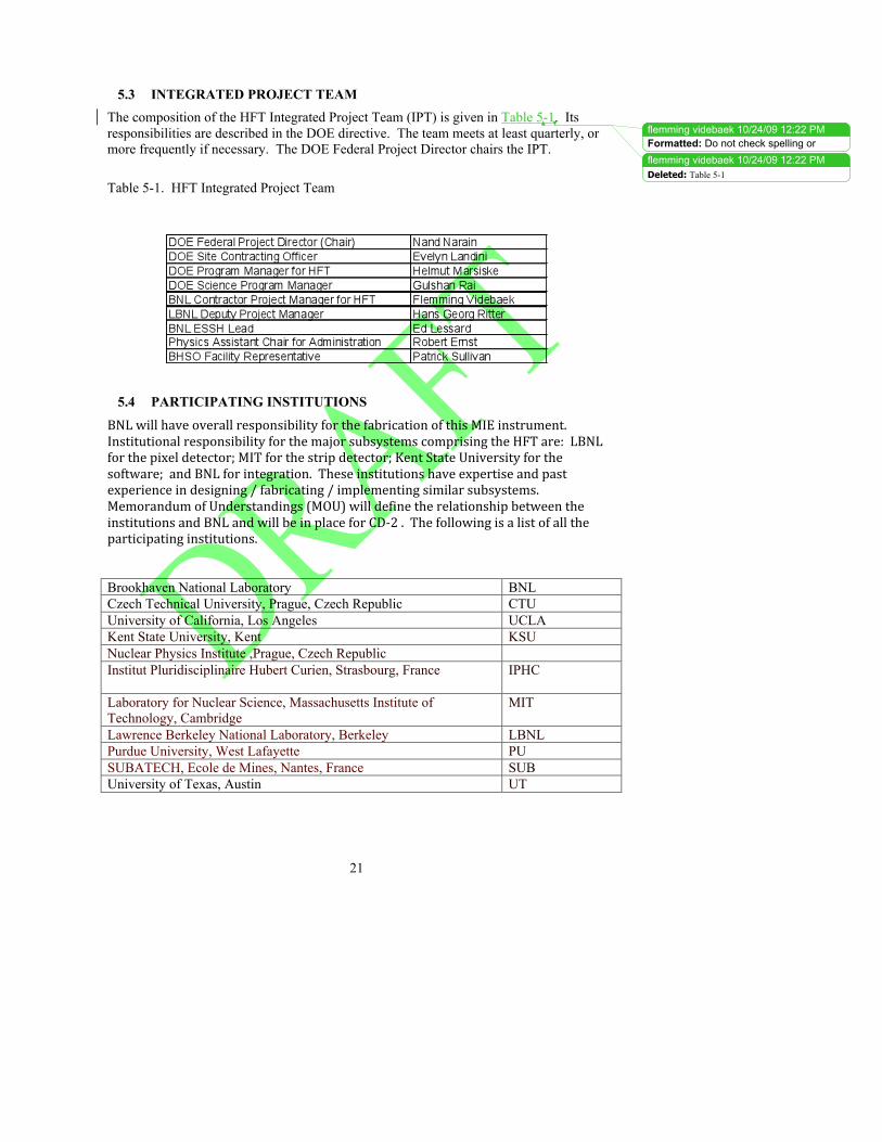
5.3 INTEGRATED PROJECT TEAM The composition of the HFT Integrated Project Team (IPT) is given in Table 5-1. Its responsibilities are described in the DOE directive. The team meets at least quarterly, or more frequently if necessary. The DOE Federal Project Director chairs the IPT. Table 5-1. HFT Integrated Project Team
5.4 PARTICIPATING INSTITUTIONS
BNL will have overall responsibility for the fabrication of this MIE instrument. Institutional responsibility for the major subsystems comprising the HFT are: LBNL for the pixel detector; MIT for the strip detector; Kent State University for the software; and BNL for integration. These institutions have expertise and past experience in designing / fabricating / implementing similar subsystems. Memorandum of Understandings (MOU) will define the relationship between the institutions and BNL and will be in place for CD‐2 . The following is a list of all the participating institutions.
Brookhaven National Laboratory BNL Czech Technical University, Prague, Czech Republic CTU University of California, Los Angeles UCLA Kent State University, Kent KSU Nuclear Physics Institute ,Prague, Czech Republic Institut Pluridisciplinaire Hubert Curien, Strasbourg, France
IPHC
Laboratory for Nuclear Science, Massachusetts Institute of Technology, Cambridge
MIT
Lawrence Berkeley National Laboratory, Berkeley LBNL Purdue University, West Lafayette PU SUBATECH, Ecole de Mines, Nantes, France SUB University of Texas, Austin UT
flemming videbaek � 10/24/09 12:22 PMFormatted: Do not check spelling orgrammarflemming videbaek � 10/24/09 12:22 PMDeleted: Table 5-1
22
5.5 OPERATION PHASE The estimated yearly cost of operation is less than $20,000 and does not include management and operations (M&O) support for the U.S. research program under the conditions set by HFT management and the required M&O and annual replacement costs for computing resources.
5.6 LIFE CYCLE COSTS The elements of the HFT could have a useful life of up to ten years. The components of a total life-cycle cost include: (a) Fabrication, as described in this document; (b) Operation; and (c) Decommissioning costs. The estimated yearly cost of operation is less than $20,000 and does not include management and operations (M&O) support for the U.S. research program under the conditions set by HFT management and the required M&O and annual replacement costs for computing resources. The decommissioning of HFT covers the disposal of standard electronic, computer, and experimental lab equipment, which must follow accepted standard procedures for disposal of these items. The decommissioning activities are not anticipated to be complex or cost prohibitive, and would likely be carried out by U.S. researchers and the STAR operations group, as is commonly done for pieces of scientific instrumentation. Although a detailed analysis has not been carried out, it is estimated that the decommissioning is likely less than $100,000. The estimated life- cycle cost is less than $18 million.
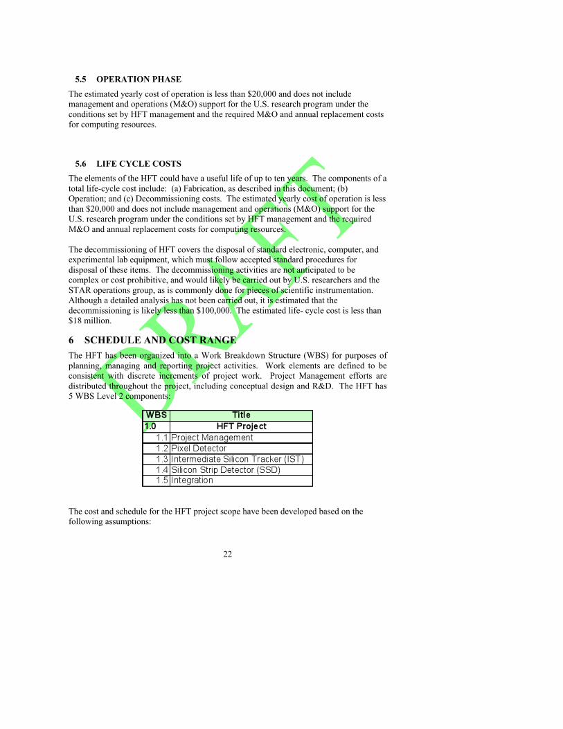
6 SCHEDULE AND COST RANGE The HFT has been organized into a Work Breakdown Structure (WBS) for purposes of planning, managing and reporting project activities. Work elements are defined to be consistent with discrete increments of project work. Project Management efforts are distributed throughout the project, including conceptual design and R&D. The HFT has 5 WBS Level 2 components:
The cost and schedule for the HFT project scope have been developed based on the following assumptions:
23
1. DOE Approval of CD-1 no later than January 2010 2. DOE Approval of CD-2/3 no later than November 2010 3. Receipt of DOE PED funding no later than January 2010 4. Receipt of DOE Construction funding no later than January 2011 5. The small radius thin-walled Be-beam pipe will be externally funded by RHIC 6. RHIC operations to be shutdown for 16 weeks in summer 2012, and for 20 weeks
in summer/fall 2014 before run- to allow time for installation/integration of HFT equipment.
7. The externally funded beam pipe has been certified and available for integration no later than October 2011 for installation of the IDS for run-13____
6.1 SCHEDULE The HFT project has two phases: assembly of PXL ladders, mechanical insertion mechanism, and the mechanical integration with the small diameter beam pipe, and the STAR detector. This is required for the engineering run with either phase-1 or ultimate sensors. This is scheduled for Q1 FY13 in time for RHIC run-13. The second phase consists of assembly of final ladders for the PXL , and the IST and SSD detectors, and is scheduled for Q2FY14. The IST and SSD detector will have been fully tested on the bench ahead of this. This funding driven schedule does not allow the full system i.e. PXL, IST and SSD to be installed in the STAR detector, since this time of year is usually during a RHIC run. Under such normal running conditions the HFT will be fully installed in STAR for run-15. The PXL detector, due to the rapid insertion mechanism, could be ready and inserted into beam during run-14. With a preliminary CD-4 date of Q1FY15and a planned early finish date of Q3FY14 for the final task assembly of IST and SSD on the support cone and verification of functionality, 12 weeks have been allocated for Performance Validation and Document development, Project Closeout, Lessons Learned. This allows approximately 30 weeks of float after the end of the early finish schedule. The critical path for EF is the production of the sensors, bonding and assembly, and testing of the ladders for the IST detector.
6.2 MILESTONES Milestones will be used as schedule events to mark the due date for accomplishment of a specified effort or objective. A milestone may mark the start, an interim step, or the end of one or more activities as needed to provide insight into the Project’s progress. Milestones are assigned to different levels (Table 6-1) depending on their importance and criticality to other milestones and the overall Project schedule.
flemming videbaek � 10/22/09 10:30 AM
flemming videbaek � 10/24/09 12:22 PM
Comment: Create a high level gant chart which include the miles stones as will be included above.
Deleted: Table 6-1
24
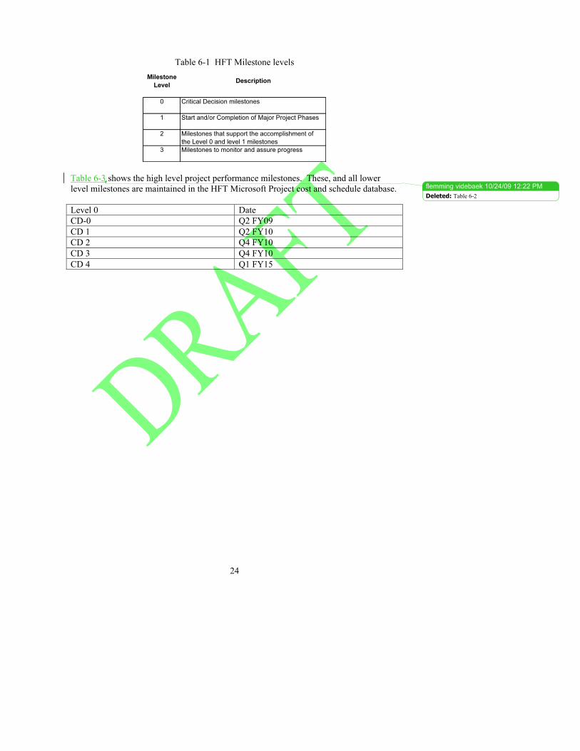
Table 6-1 HFT Milestone levels
Table 6-3 shows the high level project performance milestones. These, and all lower level milestones are maintained in the HFT Microsoft Project cost and schedule database. Level 0 Date CD-0 Q2 FY09 CD 1 Q2 FY10 CD 2 Q4 FY10 CD 3 Q4 FY10 CD 4 Q1 FY15
flemming videbaek � 10/24/09 12:22 PMDeleted: Table 6-2
25
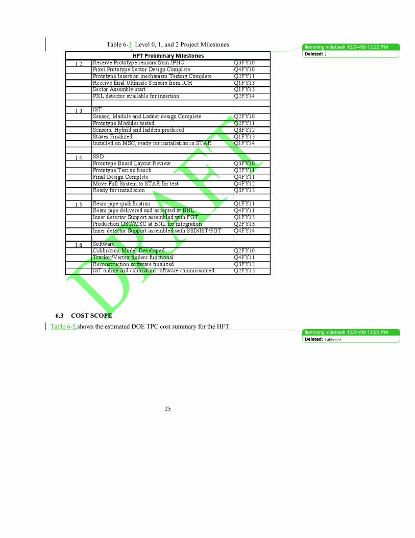
Table 6-3 Level 0, 1, and 2 Project Milestones
6.3 COST SCOPE Table 6-5 shows the estimated DOE TPC cost summary for the HFT.
flemming videbaek � 10/24/09 12:22 PM
flemming videbaek � 10/24/09 12:22 PM
Deleted: 2
Deleted: Table 6-3
26
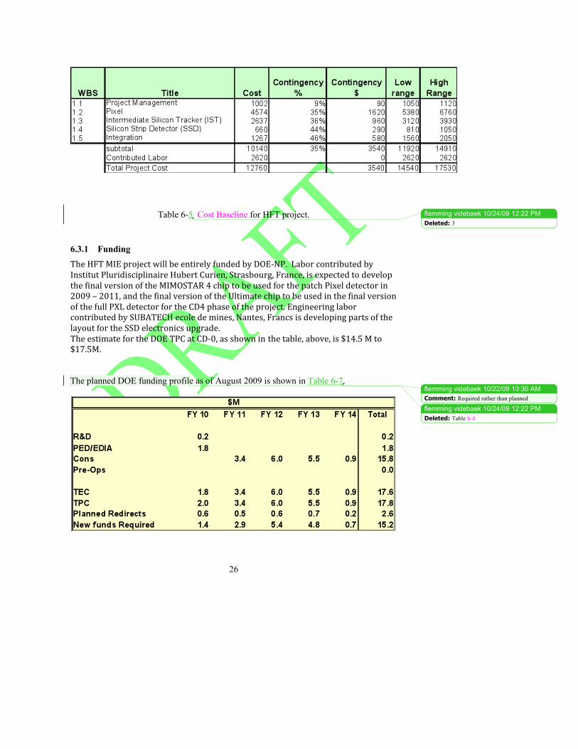
Table 6-5 Cost Baseline for HFT project.
6.3.1 Funding The HFT MIE project will be entirely funded by DOE‐NP. Labor contributed by Institut Pluridisciplinaire Hubert Curien, Strasbourg, France, is expected to develop the final version of the MIMOSTAR 4 chip to be used for the patch Pixel detector in 2009 – 2011, and the final version of the Ultimate chip to be used in the final version of the full PXL detector for the CD4 phase of the project. Engineering labor contributed by SUBATECH ecole de mines, Nantes, Francs is developing parts of the layout for the SSD electronics upgrade. The estimate for the DOE TPC at CD‐0, as shown in Xthe table, above, is $14.5 M to $17.5M. The planned DOE funding profile as of August 2009 is shown in Table 6-7.
flemming videbaek � 10/24/09 12:22 PM
flemming videbaek � 10/22/09 10:30 AM
flemming videbaek � 10/24/09 12:22 PM
Deleted: 3
Comment: Required rather than planned
Deleted: Table 6-4
27
Table 6-7 HFT Project Funding Profile in $M,
6.3.2 Contingency After the Project is baselined at CD-2 the FPD will manage the contingency funds according to the DOE Order 413.3A procedure defined in the Baseline Change Control section and as specified in the Change Control table in Table 7-1. At the present pre CD-1 phase (approved Alternate selection and Cost Range), traditional contingency percentages that varied from a low 25% for well-understood and well defined task to 50% for tasks with high associated risks were used. These contingencies percentages were based o expert judgment and were applied at the appropriate WBS level.
7 CHANGE CONTROL Changes to the technical, cost and schedule baselines will be controlled using the thresholds described in Table 7-1. All changes that include or exceed Level 3 approval thresholds (as defined in Table 7-1) should first be submitted to the CPM using a Project Change Request (PCR). For changes exceeding Level 3, the CPM will endorse the request (i.e., recommend approval) to higher authority or reject the request. If endorsed, the CPM will then transmit the PCR to the FPD with recommendations. If the request exceeds Level 2, the BHSO Baseline Change Control Board (BCCB) will submit the PCR to the FPD in DOE Headquarters for approval. All Level 2 PCRs will be reviewed and approved by the BHSO BCCB and all Level 3 PCRs will be reviewed and approved by the CPM. The BHSO BCCB will consist of the HFT FPD (chair), the BHSO Director, the Associate Director for Nuclear & Particle Physics at BNL (or designee), the Chairman of the Physics Department, the CPM, and others as directed by the FPD. Technical advisors will be included as needed in the BHSO BCCB. The chair has the final responsibility to endorse the PCR. For Level 3 changes and requests for higher-level changes the CPM will consult with the Project Engineer. If the change is approved, the copy of the approved PCR, together with any qualifications or further analysis or documentation generated in considering the request is returned to the requestor, and copies are sent to the official at the next higher control level and to HFT for filing. If approval is denied, a copy of the PCR, together with the reasons for denial, is returned to the requestor, and a copy is filed. The official at the next higher
flemming videbaek � 10/24/09 12:22 PM
flemming videbaek � 10/24/09 12:22 PM
flemming videbaek � 10/24/09 12:22 PM
flemming videbaek � 10/24/09 12:22 PM
Deleted: 4
Deleted: Table 7-1
Deleted: Table 7-1
Deleted: Table 7-1
28
control level may review the granted change to ensure proper application of the procedure and consistency of the change with the goals and boundary conditions of the project.
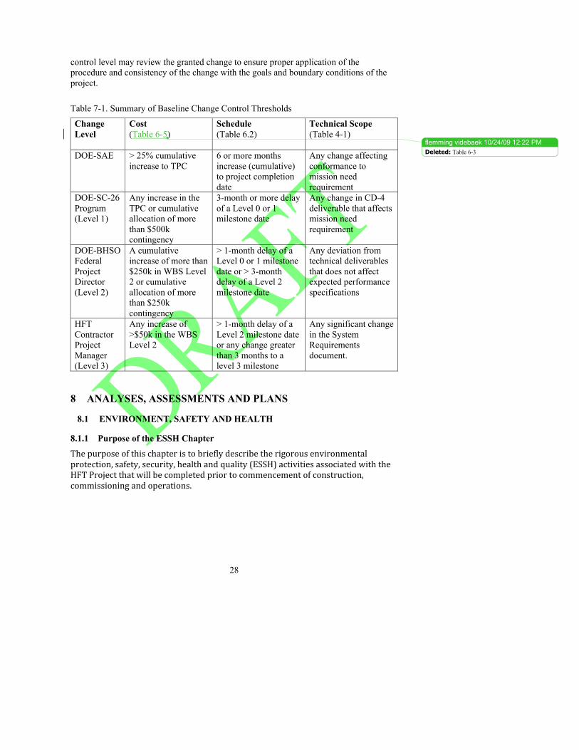
Table 7-1. Summary of Baseline Change Control Thresholds
Change Level
Cost (Table 6-5)
Schedule (Table 6.2)
Technical Scope (Table 4-1)
DOE-SAE
> 25% cumulative increase to TPC
6 or more months increase (cumulative) to project completion date
Any change affecting conformance to mission need requirement
DOE-SC-26 Program (Level 1)
Any increase in the TPC or cumulative allocation of more than $500k contingency
3-month or more delay of a Level 0 or 1 milestone date
Any change in CD-4 deliverable that affects mission need requirement
DOE-BHSO Federal Project Director (Level 2)
A cumulative increase of more than $250k in WBS Level 2 or cumulative allocation of more than $250k contingency
> 1-month delay of a Level 0 or 1 milestone date or > 3-month delay of a Level 2 milestone date
Any deviation from technical deliverables that does not affect expected performance specifications
HFT Contractor Project Manager (Level 3)
Any increase of >$50k in the WBS Level 2
> 1-month delay of a Level 2 milestone date or any change greater than 3 months to a level 3 milestone
Any significant change in the System Requirements document.
8 ANALYSES, ASSESSMENTS AND PLANS
8.1 ENVIRONMENT, SAFETY AND HEALTH
8.1.1 Purpose of the ESSH Chapter
The purpose of this chapter is to briefly describe the rigorous environmental protection, safety, security, health and quality (ESSH) activities associated with the HFT Project that will be completed prior to commencement of construction, commissioning and operations.
flemming videbaek � 10/24/09 12:22 PMDeleted: Table 6-3
29
8.1 ENVIRONMENTAL, SAFETY AND HEALTH
8.1.1 Integrated Safety Management The Integrated Safety Management (ISM) policy for this project requires full commitment to safety by the project management team. Principles of ISM are incorporated into project planning and execution. The project follows the guidelines described in the LBNL Health and Safety Manual (PUB-3000) and Integrated Environment, Health and Safety Management Plan (PUB-3140) and the BNL Standards Based Management System (SBMS). All phases of the project at other locations will be carried out under those institutions’ ES&H policies and procedures, and the HFT Project Manager will work collaboratively with those institutions to help ensure US researchers are working in an appropriately safe manner.
8.1.2 NEPA Appropriate NEPA and State environmental reviews will be completed in advance of the CD-2 review. Existing Categorical Exclusions at BNL and LBNL are adequate to cover the Project. Work at LBNL will be covered for California Environmental Quality Act (CEQA) purposes under existing CEQA documentation. Work at BNL will be carried out under all federal, state and local regulations and requirements as documented in the SBMS.
8.1.3 ESSH Plans for Construction The HFT upgrade for STAR will use the BNL Standards Based Management System (SBMS) to identify and control hazards for all equipment and work at BNL for the HFT. The Physics Department and the C-AD have review processes that comply with the BNL SBMS. The project will prepare designs and work procedures and have them reviewed by the appropriate laboratory or department review committees. Testing of equipment in Physics Department will go through the Experimental Safety Review (ESR) process (see http://www.phy.bnl.gov/~safety/ESRs/). The equipment and work practices used at STAR will be reviewed by the C-AD Experimental Safety Review Committee (ESRC). The reviews of the ESRC are covered in C-AD Operations procedures manual (OPM) chapter 9 section 2. The installation will be covered under the rules and safeguards in place for work in the RHIC experimental halls and assembly area. Refer to proper documents.. The risk analysis in the pHAD addresses the hazards of the HFT detector system. It also addresses hazards, controls and risks for experimental halls, experiments and their associated targets and detectors. The SAD follows the generally accepted principles identified in DOE Order 420.2B.
30
8.2 PROJECT QUALITY ASSURANCE PROGRAM
8.2.1 Program The project, through the Physics Department, shall adopt in its entirety the BNL Quality Assurance (QA) Program. This QA Program describes how the various BNL management system processes and functions provide a management approach which conforms to the basic requirements defined in DOE Order 414.1B, Quality Assurance.
The quality program embodies the concept of the “graded approach” i.e., the selection and application of appropriate technical and administrative controls to work activities, equipment and items commensurate with the associated environment, safety and health risks and programmatic impact. The graded approach does not allow internal or external requirements to be ignored or waived, but does allow the degree of controls, verification, and documentation to be varied in meeting requirements based on environment, safety and health risks and programmatic issues. Prior to CD-2 the HFT project team will define a HFT QA-plan.
The BNL QA Program shall be implemented within the Project.
Quality Board Representatives have been assigned to serve as a focal point to assist management in implementing QA program requirements. The Quality Board has the authority to assist sub-system managers in identifying potential and actual problems that could degrade the quality of a process/item or work performance, recommend corrective actions, and verify implementation of approved solutions.
8.2.2 Documents and Records The BNL Records Management System and controlled document Subject Areas within SBMS, provide the requirements and guidance for the development, review, approval, control and maintenance of documents and records.
8.2.3 Work Process Work is performed employing processes deployed through the BNL SBMS. SBMS Subject Areas are used to implement BNL-wide practices for work performed. Subject Areas are developed in a manner that provides sufficient operating instructions for most activities. Design Design planning shall establish the milestones at which design criteria, standards, specifications, drawings and other design documents will be prepared, reviewed, approved and released. The design criteria shall define the performance objectives, operating conditions, and requirements for safety, reliability, maintainability and availability, as well as the requirements for materials, fabrication, construction, and
31
testing. Appropriate codes, standards and practices for materials, fabrication, construction, testing, and processes shall be defined in the design documentation. Where feasible, nationally recognized codes, standards and practices shall be used. When those are either overly restrictive, or fall short of defining the requirements, they shall be modified, supplemented, or replaced by BNL specifications.
Specifications, drawings and other design documents present verifiable engineering delineations in pictorial and/or descriptive language representations of parts, components or assemblies for HFT
Procurement Personnel responsible for the design or performance of items or services to be purchased shall ensure that the procurement requirements of the purchase request are clear and complete. Using the graded approach, potential suppliers of critical, complex, or costly items or services shall be evaluated in accordance with predetermined criteria to ascertain that they have the capability to provide items or services which conform with the technical and quality requirements of the procurement. The evaluation shall include a review of the supplier's history with BNL or other DOE facilities Inspection and Acceptance Testing The BNL Quality Management System within the SBMS, provides processes for the inspection and acceptance testing of an item, service or process against established criteria and provides a means of determining acceptability. Based on the graded approach, the need and/or degree of inspection and acceptance testing shall be determined during the activity/item design stage. Inspection/test planning has as an objective the prompt detection of non-conformances that could adversely affect performance, safety, reliability, schedule or cost. 9 PROJECT CONTROLS AND REPORTING SYSTEMS The HFT project has been entered into the Project Assessment and Reporting System (PARS) and is updated on a monthly basis by the FPD.
The CPM leads monthly cost and schedule reviews and reports the result to the FPD. In addition, he leads quarterly overall cost, schedule and technical performance reviews and reports the results to the BHSO-DOE office. The FPD reports progress to the DOE Program Manager on a quarterly basis. The FPD and CPM participate in monthly teleconference calls with the DOE Office of Nuclear Physics. The Office of Nuclear Physics conducts annual progress reviews with a panel of experts.
The standard BNL accounting system is the basis for collecting cost data, and the Control Account structure for HFT will separate costs according to funded phase (R&D, PED, Construction, Pre-Ops), and WBS. A direct one-to-one relationship will be established
32
between each WBS element of Level 2 or lower and a separate control account in the BNL accounting system. Technical performance is monitored throughout the project to insure conformance to approved functional requirements. Design reviews and performance testing of the completed systems are used to ensure that the equipment meets the functional requirements. Some Program and Project Controls are described in detail in separate HFT documents, and are revised as needed throughout the project:
• Risk Management Plan, and the Risk List.
9.1 VALUE ENGINEERING
A Value Engineering (VE) study will be performed before the HFT project seeks approval for CD‐2/CD‐3. The study will follow the traditional approach to VE, according to applicable procedures. A review team formed by members of the IPT and representatives of the HFT management and technical teams will evaluate alternative design approaches and evaluate the flexibility of the design for present and future research. The VE approach will determine the impacts on cost (both HFT and life‐cycle) of any suggested changes to the design. Additionally, the project team will perform informal VE evaluations throughout the duration of this MIE.