Prediction of tread block forces for a free-rolling tyre in contact with a smooth road
12
Wear 269 (2010) 672–683 Contents lists available at ScienceDirect Wear journal homepage: www.elsevier.com/locate/wear Prediction of tread block forces for a free-rolling tyre in contact with a smooth road F. Liu, M.P.F. Sutcliffe ∗ , W.R. Graham Department of Engineering, University of Cambridge, Trumpington Street, Cambridge CB2 1PZ, UK article info Article history: Received 6 July 2009 Received in revised form 6 July 2010 Accepted 9 July 2010 Available online 16 July 2010 Keywords: Tyre Tread block Contact mechanics Viscoelastic spring model Finite element modelling abstract This paper presents a model for the contact mechanics of tread blocks on a free-rolling pneumatic tyre, of a complexity intermediate between sophisticated 3D finite element (FE) analyses and simple brush models. The model is able to capture the essential physics of the contact while being sufficiently simple to be incorporated into dynamic tyre models, such as can be used to predict hub forces. The tread blocks are represented by a ‘brush-type’ spring model, taking into account the geometry of the contact and shear deformations of the tread. The rubber is represented as a linear viscoelastic material. The spring model is found to give similar normal and shear force predictions to a more sophisticated finite element analysis undertaken in the paper, both for tread blocks mounted on a deformed tyre belt (with the geometry taken from measurements of a loaded tyre) and for blocks on a rigid cylinder, matching the geometry of a small-scale rolling contact test rig. Predictions compare reasonably with measurements on the rig of tread block normal and tangential forces. © 2010 Elsevier B.V. All rights reserved. 1. Introduction Tyres on a passenger vehicle, besides generating noise outside the vehicle cabin, also transmit forces associated with the road con- ditions and their own vibrations into the vehicle hubs via the wheel rims on which they are mounted. As the input stimuli to the vehi- cle suspension system, the dynamic hub forces have been a topic of interest for automobile manufacturers. At the design stage of a passenger vehicle, it is desirable for the automobile manufacturers to have predictive tools to characterise the hub forces for frequen- cies up to 1 kHz [1]. Since the unsteady forcing of vehicle hubs is a direct result of the dynamic behaviour of tyres, an advanced tyre model has an essential role in developing such tools. Recently, Lecomte et al. [2] have developed a theoretical tyre belt vibration model that shows excellent correlation with the exper- imental results below 300 Hz and satisfactory agreement up to 1 kHz. As part of the same project, we have presented a simplified yet robust tread block contact mechanics model to provide input stimuli to Lecomte et al.’s tyre belt vibration model [3]. The aim of the approach described in [3] and developed further in this paper is to provide as simple a description as possible to capture the essen- tial physics of the contact and provide the necessary inputs to such tyre belt representations. In a similar vein Wullens and Kropp [4] describe a coupled contact and tyre structure model for prediction ∗ Corresponding author. Tel.: +44 01223 332996; fax: +44 01223 332662. E-mail address: [email protected] (M.P.F. Sutcliffe). of tyre/road noise. The simplicity of the proposed contact model is a requirement of the computational intensity of the tyre vibra- tion calculation, which requires a time-stepping simulation. The tread contact model is a relatively small part of the overall solution method and needs to be correspondingly straightforward to imple- ment. This rules out use of the well-established finite element (FE) method for describing the contact, although we recognise that such an approach can provide a useful tool to model the contact prob- lem, and indeed is used as a benchmark in this paper. Ghoreishy [5] presents a comprehensive survey of finite element models of rolling tyres, while typical examples by Sujin et al. [6] and Hall et al. [7] show how details of the contact geometry can indeed be calculated. The simplest material model for rubber is linear elastic. This approach is used by Wullens and Kropp [4], taking advantage of analytical solutions for such a simple representation to allow inclu- sion of tyre–road interactions. Non-linear elastic effects associated with large strains can be accommodated using a hyper-elastic model, as adopted for example by Sujin et al. [6] and Hall et al. [7]. Rubber is a viscoelastic material so it is not surprising that var- ious forms of viscoelastic model have also been used to describe tyre mechanics, either explicitly in the material model or implic- itly via spring-damper formulations. Cesbron et al. [8] list a range of examples, noting that their experimental results can be explained in terms of such viscoelastic behaviour. Non-linear behaviour (i.e. a strain dependence) is also relevant to viscoelastic models [9]. This point may be particularly relevant to rough road contacts (not con- sidered in this paper) where local strains in the tread may be higher than the corresponding smooth road contact. Standard methods 0043-1648/$ – see front matter © 2010 Elsevier B.V. All rights reserved. doi:10.1016/j.wear.2010.07.006
Transcript of Prediction of tread block forces for a free-rolling tyre in contact with a smooth road

Ps
FD
a
ARRAA
KTTCVF
1
tdrcoptcdm
vi1ysttttd
0d
Wear 269 (2010) 672–683
Contents lists available at ScienceDirect
Wear
journa l homepage: www.e lsev ier .com/ locate /wear
rediction of tread block forces for a free-rolling tyre in contact with amooth road
. Liu, M.P.F. Sutcliffe ∗, W.R. Grahamepartment of Engineering, University of Cambridge, Trumpington Street, Cambridge CB2 1PZ, UK
r t i c l e i n f o
rticle history:eceived 6 July 2009eceived in revised form 6 July 2010ccepted 9 July 2010vailable online 16 July 2010
a b s t r a c t
This paper presents a model for the contact mechanics of tread blocks on a free-rolling pneumatic tyre,of a complexity intermediate between sophisticated 3D finite element (FE) analyses and simple brushmodels. The model is able to capture the essential physics of the contact while being sufficiently simpleto be incorporated into dynamic tyre models, such as can be used to predict hub forces. The tread blocks
eywords:yreread blockontact mechanicsiscoelastic spring model
are represented by a ‘brush-type’ spring model, taking into account the geometry of the contact and sheardeformations of the tread. The rubber is represented as a linear viscoelastic material. The spring model isfound to give similar normal and shear force predictions to a more sophisticated finite element analysisundertaken in the paper, both for tread blocks mounted on a deformed tyre belt (with the geometrytaken from measurements of a loaded tyre) and for blocks on a rigid cylinder, matching the geometry ofa small-scale rolling contact test rig. Predictions compare reasonably with measurements on the rig of
ngen
inite element modelling tread block normal and ta. Introduction
Tyres on a passenger vehicle, besides generating noise outsidehe vehicle cabin, also transmit forces associated with the road con-itions and their own vibrations into the vehicle hubs via the wheelims on which they are mounted. As the input stimuli to the vehi-le suspension system, the dynamic hub forces have been a topicf interest for automobile manufacturers. At the design stage of aassenger vehicle, it is desirable for the automobile manufacturerso have predictive tools to characterise the hub forces for frequen-ies up to 1 kHz [1]. Since the unsteady forcing of vehicle hubs is airect result of the dynamic behaviour of tyres, an advanced tyreodel has an essential role in developing such tools.Recently, Lecomte et al. [2] have developed a theoretical tyre belt
ibration model that shows excellent correlation with the exper-mental results below 300 Hz and satisfactory agreement up tokHz. As part of the same project, we have presented a simplifiedet robust tread block contact mechanics model to provide inputtimuli to Lecomte et al.’s tyre belt vibration model [3]. The aim ofhe approach described in [3] and developed further in this paper is
o provide as simple a description as possible to capture the essen-ial physics of the contact and provide the necessary inputs to suchyre belt representations. In a similar vein Wullens and Kropp [4]escribe a coupled contact and tyre structure model for prediction∗ Corresponding author. Tel.: +44 01223 332996; fax: +44 01223 332662.E-mail address: [email protected] (M.P.F. Sutcliffe).
043-1648/$ – see front matter © 2010 Elsevier B.V. All rights reserved.oi:10.1016/j.wear.2010.07.006
tial forces.© 2010 Elsevier B.V. All rights reserved.
of tyre/road noise. The simplicity of the proposed contact modelis a requirement of the computational intensity of the tyre vibra-tion calculation, which requires a time-stepping simulation. Thetread contact model is a relatively small part of the overall solutionmethod and needs to be correspondingly straightforward to imple-ment. This rules out use of the well-established finite element (FE)method for describing the contact, although we recognise that suchan approach can provide a useful tool to model the contact prob-lem, and indeed is used as a benchmark in this paper. Ghoreishy [5]presents a comprehensive survey of finite element models of rollingtyres, while typical examples by Sujin et al. [6] and Hall et al. [7]show how details of the contact geometry can indeed be calculated.
The simplest material model for rubber is linear elastic. Thisapproach is used by Wullens and Kropp [4], taking advantage ofanalytical solutions for such a simple representation to allow inclu-sion of tyre–road interactions. Non-linear elastic effects associatedwith large strains can be accommodated using a hyper-elasticmodel, as adopted for example by Sujin et al. [6] and Hall et al.[7]. Rubber is a viscoelastic material so it is not surprising that var-ious forms of viscoelastic model have also been used to describetyre mechanics, either explicitly in the material model or implic-itly via spring-damper formulations. Cesbron et al. [8] list a range ofexamples, noting that their experimental results can be explained
in terms of such viscoelastic behaviour. Non-linear behaviour (i.e. astrain dependence) is also relevant to viscoelastic models [9]. Thispoint may be particularly relevant to rough road contacts (not con-sidered in this paper) where local strains in the tread may be higherthan the corresponding smooth road contact. Standard methods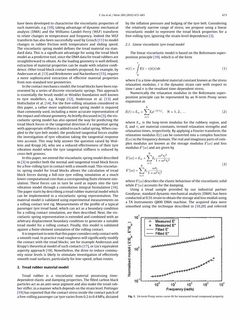
r 269
hsattcTdmsedAaf
ritHtttctwptilvc
iftbluvTcmapfcata
atKans
2
dpb[a
Using a tread sample provided by our industrial partnerGoodyear, standard dynamic mechanical analysis (DMA) has beenconducted at 0.5% strain to obtain the storage and loss moduli usinga TA Instruments Q800 DMA machine. The acquired data weresmoothed using the technique described in [10,20] and referred
F. Liu et al. / Wea
ave been developed to characterise the viscoelastic properties ofuch materials, e.g. [10], taking advantage of dynamic mechanicalnalysis (DMA) and the Williams–Landel–Ferry (WLF) transformo relate changes in temperature and frequency. Indeed the WLFransform has also been successfully used by Grosch [11] to modelhanges in rubber friction with temperature and sliding speed.he viscoelastic spring model defines the tread material via stan-ard data. This is a significant advantage for using the tread blockodel as a predictive tool, since the DMA data for tread rubbers are
traightforward to obtain. As the loading geometry is well defined,xtraction of material properties can be made with relative confi-ence. Other tread block contact models proposed, for example, byndersson et al. [13] and Brinkmeier and Nackenhorst [15], requiremore sophisticated extraction of effective material properties
rom non-standard test geometries.In the contact mechanics model, the tread blocks have been rep-
esented by a series of discrete viscoelastic springs. This approachs essentially the brush model or Winkler foundation well knowno tyre modellers, e.g. Kropp [12], Andersson et al. [13] andoltschulze et al. [14]. For the free-rolling situation considered in
his paper, a rather more sophisticated spring model is requiredhan commonly used, including a more accurate representation ofhe impact and release geometry. As briefly discussed in [3], the vis-oelastic spring model has also opened the way for predicting theread block forces in the tangential direction if a tangential springith appropriate stiffness is added to each radial spring. When cou-led to the tyre belt model, the predicted tangential forces enablehe investigation of tyre vibration taking the tangential responsento account. This may help answer the question raised by Wul-ens and Kropp [4], who see a reduced effectiveness of their tyreibration model when the tyre tangential stiffness is reduced byross-belt grooves.
In this paper, we extend the viscoelastic spring model describedn [3] to predict both the normal and tangential tread block forcesor a free-rolling tyre in contact with a smooth road. This viscoelas-ic spring model for tread blocks allows the calculation of treadlock forces during a full-size tyre rolling simulation at a much
ower computational cost than a corresponding finite element sim-lation. These forces can in turn be used as inputs into the tyreibration model through a convolution integral formulation [16].he paper starts by describing a tread rubber material model whichan be implemented in a viscoelastic spring representation. Theaterial model is validated using experimental measurements onrolling contact test rig. Measurements of the profile of a typicalassenger tyre tread band, which can act as a boundary conditionor a rolling contact simulation, are then described. Next, the vis-oelastic spring representation is extended and combined with anrbitrary displacement boundary condition to generate a suitableread model for a rolling contact. Finally, this model is validatedgainst a finite element simulation of the rolling contact.
It is important to note that this paper considers only contact withsmooth road. In practice road roughness will significantly modify
he contact with the tread blocks; see for example Andersson andropp’s theoretical model of such contacts [17], or Liu’s equivalentsperity approach [18]. Nonetheless, the drive to reduce commu-ity noise levels is likely to stimulate investigation of effectivelymooth road surfaces, particularly for low-speed, urban routes.
. Tread rubber material model
Tread rubber is a viscoelastic material possessing time-
ependent elastic and damping properties. The filled carbon blackarticles act as an anti-wear pigment and also make the tread rub-er stiffer, in a manner which depends on the strain level. Pottinger19] has reported that the contact stress inside the contact patch offree-rolling passenger car tyre varies from 0.2 to 0.4 MPa, dictated(2010) 672–683 673
by the inflation pressure and bulging of the tyre belt. Consideringthe relatively narrow range of stress, we propose using a linearviscoelastic model to represent the tread block properties for afree-rolling tyre, ignoring the strain-level dependence [3].
2.1. Linear viscoelastic tyre tread model
The linear viscoelastic model is based on the Boltzmann super-position principle [10], which is of the form
�(t) =t∫
0
E(t − s)ε̇(s)ds (1)
where E is a time-dependent material constant known as the stressrelaxation modulus, ε̇ is the dynamic strain rate with respect totime t and � is the resultant time-dependent stress.
Numerically the relaxation modulus in the Boltzmann super-position principle can be represented by an N-term Prony seriesexpansion as
E(t) = E∞ +N∑i=1
Eie−(t/�i), N = 1,2, . . . (2)
where E∞ is the long-term modulus for the rubbery region, andEi and �i are material constants, termed relaxation strengths andrelaxation times, respectively. By applying a Fourier transform, therelaxation modulus E(t) can be converted into a complex functionE(ω) in the frequency domain. The real and imaginary parts of com-plex modulus are known as the storage modulus E′(ω) and lossmodulus E′′(ω) and are given by
E′(ω) = E∞ +N∑i=1
Eiω2�i
2
1 +ω2�i2
E′′(ω) =N∑i=1
Eiω�i
1 +ω2�i2
(3)
where E′(ω) describes the elastic behaviour of the viscoelastic solidwhile E′′(ω) accounts for the damping.
Fig. 1. 24-term Prony series curve-fit for measured tread compound property.
674 F. Liu et al. / Wear 269 (2010) 672–683
lock r
twtwbafaattotdb
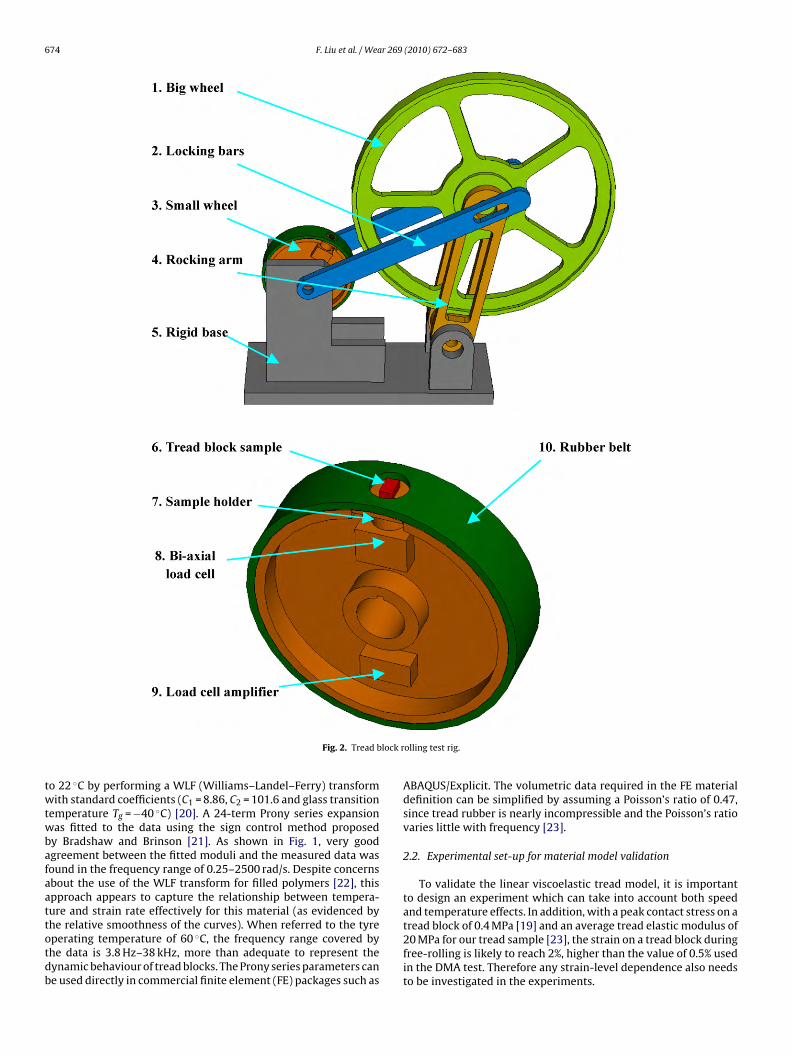
Fig. 2. Tread b
o 22 ◦C by performing a WLF (Williams–Landel–Ferry) transformith standard coefficients (C1 = 8.86, C2 = 101.6 and glass transition
emperature Tg = −40 ◦C) [20]. A 24-term Prony series expansionas fitted to the data using the sign control method proposed
y Bradshaw and Brinson [21]. As shown in Fig. 1, very goodgreement between the fitted moduli and the measured data wasound in the frequency range of 0.25–2500 rad/s. Despite concernsbout the use of the WLF transform for filled polymers [22], thispproach appears to capture the relationship between tempera-ure and strain rate effectively for this material (as evidenced by
he relative smoothness of the curves). When referred to the tyreperating temperature of 60 ◦C, the frequency range covered byhe data is 3.8 Hz–38 kHz, more than adequate to represent theynamic behaviour of tread blocks. The Prony series parameters cane used directly in commercial finite element (FE) packages such asolling test rig.
ABAQUS/Explicit. The volumetric data required in the FE materialdefinition can be simplified by assuming a Poisson’s ratio of 0.47,since tread rubber is nearly incompressible and the Poisson’s ratiovaries little with frequency [23].
2.2. Experimental set-up for material model validation
To validate the linear viscoelastic tread model, it is importantto design an experiment which can take into account both speedand temperature effects. In addition, with a peak contact stress on a
tread block of 0.4 MPa [19] and an average tread elastic modulus of20 MPa for our tread sample [23], the strain on a tread block duringfree-rolling is likely to reach 2%, higher than the value of 0.5% usedin the DMA test. Therefore any strain-level dependence also needsto be investigated in the experiments.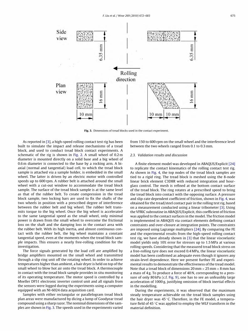
F. Liu et al. / Wear 269 (2010) 672–683 675
cks u
bbsd0aswswsabtbmtpltttpi
bttsioMte
pcp
Fig. 3. Dimensions of tread blo
As reported in [3], a high-speed rolling contact test rig has beenuilt to simulate the impact and release mechanisms of a treadlock, and used to conduct tread block contact experiments. Achematic of the rig is shown in Fig. 2. A small wheel of 0.2 miameter is mounted directly on a solid base and a big wheel of.6 m diameter is connected to the base by a rocking arm. A bi-xial (normal and tangential) load cell, to which the tread blockample is attached via a sample holder, is embedded in the smallheel. The latter is driven by an electric motor with controlled
peeds up to 600 rpm. A rubber belt is attached around the smallheel with a cut-out window to accommodate the tread block
ample. The surface of the tread block sample is at the same levels that of the rubber belt. To create compression in the treadlock sample, two locking bars are used to fix the shafts of thewo wheels in position with a prescribed degree of interferenceetween the rubber belt and big wheel. The rubber belt trans-its torque to the big wheel. Once the big wheel is accelerated
o the same tangential speed as the small wheel, only minimalower is drawn from the small wheel to overcome the frictional
oss on the shaft and the damping loss in the contact area withhe rubber belt. With its high inertia, and almost continuous con-act with the rubber belt, the big wheel maintains a constantangential speed, even at the moments when the tread block sam-le impacts. This ensures a nearly free-rolling condition for the
nvestigation.The force signals generated by the load cell are amplified by
ridge amplifiers mounted on the small wheel and transmittedhrough a slip ring unit off the rotating wheel. In order to achieveemperatures higher than ambient, a hair dryer is held on top of themall wheel to blow hot air onto the tread block. A thermocouplen contact with the tread block sample provides in situ monitoringf its operating temperature. The motor speed is controlled by aoeller DF51 electronic inverter control unit and all signals from
he sensors were logged during the experiments using a computer
quipped with an NI-6024 data acquisition card.Samples with either rectangular or parallelogram tread blocklan areas were manufactured by dicing a lump of Goodyear treadompound using a sharp razor. The nominal dimensions of the sam-les are shown in Fig. 3. The speeds used in the experiments varied
sed in the contact experiment.
from 150 to 600 rpm on the small wheel and the interference levelbetween the two wheels ranged from 0.1 to 0.3 mm.
2.3. Validation results and discussion
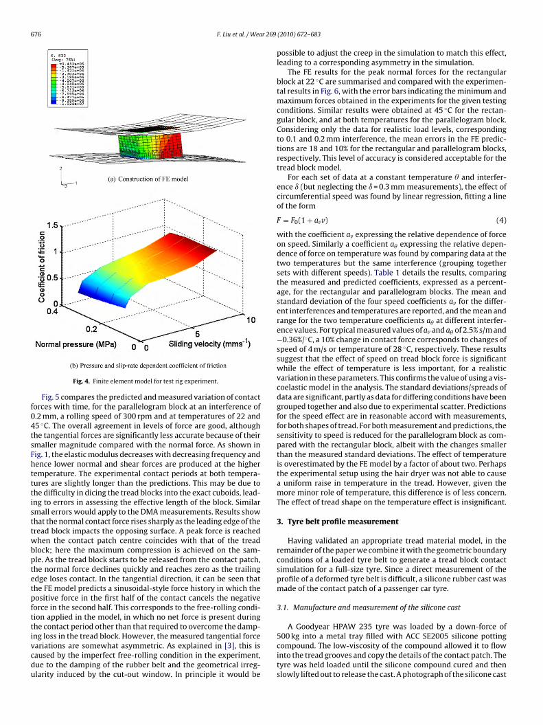
A finite element model was developed in ABAQUS/Explicit [24]to replicate the contact kinematics of the rolling contact test rig.As shown in Fig. 4, the top nodes of the tread block samples aretied to a rigid ring. The tread block is meshed using the 8-nodelinear brick element C3D8R with reduced integration and hour-glass control. The mesh is refined at the bottom contact surfaceof the tread block. The ring rotates at a prescribed speed to bringthe tread block into contact with the opposing surface. A pressureand slip-rate dependent coefficient of friction, shown in Fig. 4, wasobtained for the tread/steel contact pair in the rolling test rig, basedon a measurement conducted using a linear tribometer [3]. Usingthe VFRIC subroutine in ABAQUS/Explicit, this coefficient of frictionwas applied to the contact surfaces in the model. The friction modelis implemented in ABAQUS via contact elements defining contactconstraints and over-closure at integration points. The constraintsare imposed using Lagrange multipliers [24]. By comparing the FEand the experimental results from the high-speed rolling contacttest rig, we have already shown in [3] that the linear viscoelasticmodel yields only 10% error for stresses up to 1.5 MPa at variousrolling speeds. Considering that the measured tread block stress ona free-rolling tyre does not exceed 0.4 MPa, the linear viscoelasticmodel has been confirmed as adequate even though it ignores anystrain-level dependence. Here we present further FE and experi-mental results to demonstrate the effectiveness of the tread model.Note that a tread block of dimensions 20 mm × 25 mm × 8 mm hasa mass of 4 g. To produce a force of 40 N, corresponding to a pres-sure of only 80 kPa (c.f. Fig. 9), one has to see an unfeasibly largeacceleration of 1000 g, justifying omission of block inertial effectsin the modelling.
During the experiments, it was observed that the maximumsteady temperature achievable on the tread block samples usingthe hair dryer was 45 ◦C. Therefore, in the FE model, a tempera-ture field of 45 ◦C was applied to employ the WLF transform in thematerial definition.
676 F. Liu et al. / Wear 269
f04tsFhtttisttwbptetpfttivcdu
Fig. 4. Finite element model for test rig experiment.
Fig. 5 compares the predicted and measured variation of contactorces with time, for the parallelogram block at an interference of.2 mm, a rolling speed of 300 rpm and at temperatures of 22 and5 ◦C. The overall agreement in levels of force are good, althoughhe tangential forces are significantly less accurate because of theirmaller magnitude compared with the normal force. As shown inig. 1, the elastic modulus decreases with decreasing frequency andence lower normal and shear forces are produced at the higheremperature. The experimental contact periods at both tempera-ures are slightly longer than the predictions. This may be due tohe difficulty in dicing the tread blocks into the exact cuboids, lead-ng to errors in assessing the effective length of the block. Similarmall errors would apply to the DMA measurements. Results showhat the normal contact force rises sharply as the leading edge of theread block impacts the opposing surface. A peak force is reachedhen the contact patch centre coincides with that of the tread
lock; here the maximum compression is achieved on the sam-le. As the tread block starts to be released from the contact patch,he normal force declines quickly and reaches zero as the trailingdge loses contact. In the tangential direction, it can be seen thathe FE model predicts a sinusoidal-style force history in which theositive force in the first half of the contact cancels the negativeorce in the second half. This corresponds to the free-rolling condi-ion applied in the model, in which no net force is present duringhe contact period other than that required to overcome the damp-
ng loss in the tread block. However, the measured tangential forceariations are somewhat asymmetric. As explained in [3], this isaused by the imperfect free-rolling condition in the experiment,ue to the damping of the rubber belt and the geometrical irreg-larity induced by the cut-out window. In principle it would be(2010) 672–683
possible to adjust the creep in the simulation to match this effect,leading to a corresponding asymmetry in the simulation.
The FE results for the peak normal forces for the rectangularblock at 22 ◦C are summarised and compared with the experimen-tal results in Fig. 6, with the error bars indicating the minimum andmaximum forces obtained in the experiments for the given testingconditions. Similar results were obtained at 45 ◦C for the rectan-gular block, and at both temperatures for the parallelogram block.Considering only the data for realistic load levels, correspondingto 0.1 and 0.2 mm interference, the mean errors in the FE predic-tions are 18 and 10% for the rectangular and parallelogram blocks,respectively. This level of accuracy is considered acceptable for thetread block model.
For each set of data at a constant temperature � and interfer-ence ı (but neglecting the ı= 0.3 mm measurements), the effect ofcircumferential speed was found by linear regression, fitting a lineof the form
F = F0(1 + avv) (4)
with the coefficient av expressing the relative dependence of forceon speed. Similarly a coefficient a� expressing the relative depen-dence of force on temperature was found by comparing data at thetwo temperatures but the same interference (grouping togethersets with different speeds). Table 1 details the results, comparingthe measured and predicted coefficients, expressed as a percent-age, for the rectangular and parallelogram blocks. The mean andstandard deviation of the four speed coefficients av for the differ-ent interferences and temperatures are reported, and the mean andrange for the two temperature coefficients a� at different interfer-ence values. For typical measured values of av and a� of 2.5% s/m and−0.36%/◦C, a 10% change in contact force corresponds to changes ofspeed of 4 m/s or temperature of 28 ◦C, respectively. These resultssuggest that the effect of speed on tread block force is significantwhile the effect of temperature is less important, for a realisticvariation in these parameters. This confirms the value of using a vis-coelastic model in the analysis. The standard deviations/spreads ofdata are significant, partly as data for differing conditions have beengrouped together and also due to experimental scatter. Predictionsfor the speed effect are in reasonable accord with measurements,for both shapes of tread. For both measurement and predictions, thesensitivity to speed is reduced for the parallelogram block as com-pared with the rectangular block, albeit with the changes smallerthan the measured standard deviations. The effect of temperatureis overestimated by the FE model by a factor of about two. Perhapsthe experimental setup using the hair dryer was not able to causea uniform raise in temperature in the tread. However, given themore minor role of temperature, this difference is of less concern.The effect of tread shape on the temperature effect is insignificant.
3. Tyre belt profile measurement
Having validated an appropriate tread material model, in theremainder of the paper we combine it with the geometric boundaryconditions of a loaded tyre belt to generate a tread block contactsimulation for a full-size tyre. Since a direct measurement of theprofile of a deformed tyre belt is difficult, a silicone rubber cast wasmade of the contact patch of a passenger car tyre.
3.1. Manufacture and measurement of the silicone cast
A Goodyear HPAW 235 tyre was loaded by a down-force of
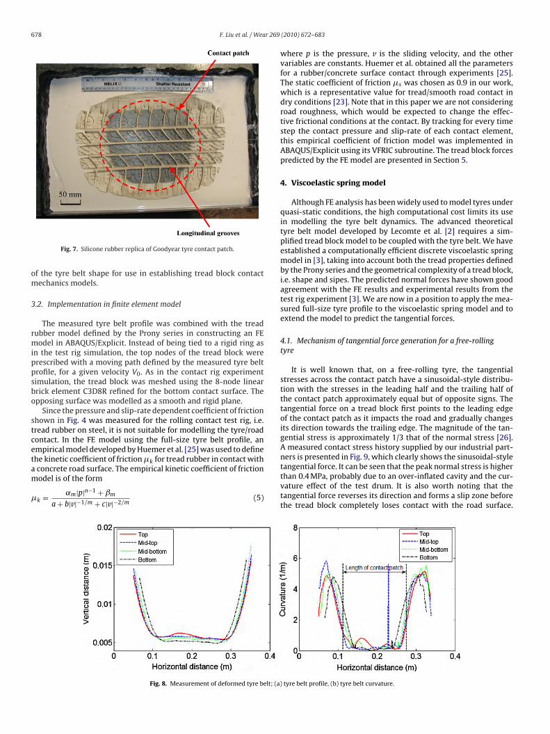
500 kg into a metal tray filled with ACC SE2005 silicone pottingcompound. The low-viscosity of the compound allowed it to flowinto the tread grooves and copy the details of the contact patch. Thetyre was held loaded until the silicone compound cured and thenslowly lifted out to release the cast. A photograph of the silicone cast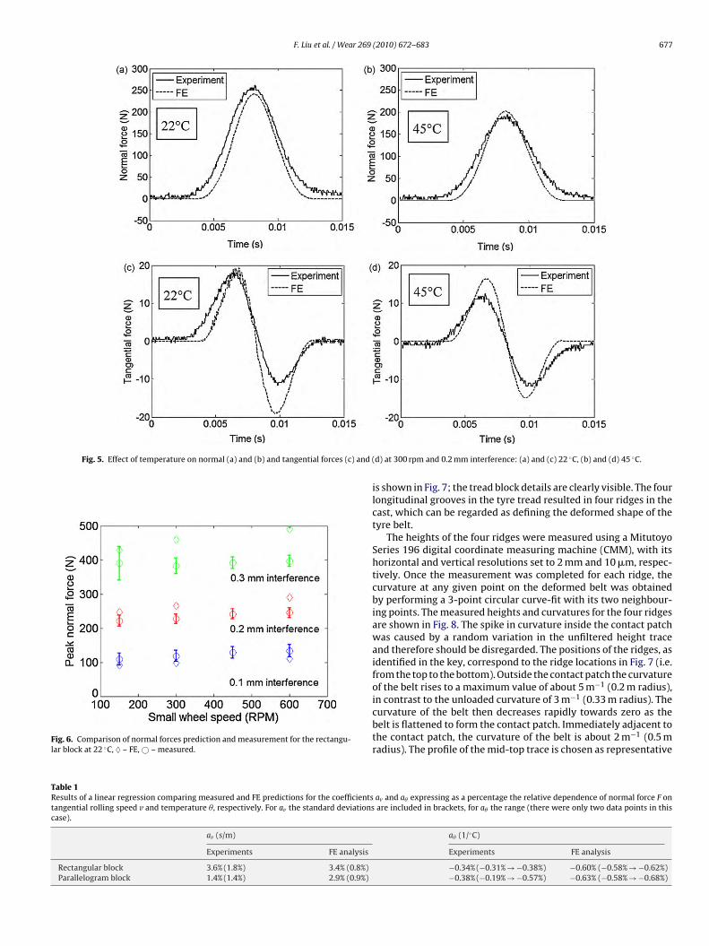
F. Liu et al. / Wear 269 (2010) 672–683 677
Fig. 5. Effect of temperature on normal (a) and (b) and tangential forces (c) and
Fig. 6. Comparison of normal forces prediction and measurement for the rectangu-lar block at 22 ◦C, ♦ – FE, © – measured.
Table 1Results of a linear regression comparing measured and FE predictions for the coefficientstangential rolling speed v and temperature �, respectively. For av the standard deviationscase).
av (s/m)
Experiments FE analysis
Rectangular block 3.6% (1.8%) 3.4% (0.8%)Parallelogram block 1.4% (1.4%) 2.9% (0.9%)
(d) at 300 rpm and 0.2 mm interference: (a) and (c) 22 ◦C, (b) and (d) 45 ◦C.
is shown in Fig. 7; the tread block details are clearly visible. The fourlongitudinal grooves in the tyre tread resulted in four ridges in thecast, which can be regarded as defining the deformed shape of thetyre belt.
The heights of the four ridges were measured using a MitutoyoSeries 196 digital coordinate measuring machine (CMM), with itshorizontal and vertical resolutions set to 2 mm and 10 �m, respec-tively. Once the measurement was completed for each ridge, thecurvature at any given point on the deformed belt was obtainedby performing a 3-point circular curve-fit with its two neighbour-ing points. The measured heights and curvatures for the four ridgesare shown in Fig. 8. The spike in curvature inside the contact patchwas caused by a random variation in the unfiltered height traceand therefore should be disregarded. The positions of the ridges, asidentified in the key, correspond to the ridge locations in Fig. 7 (i.e.from the top to the bottom). Outside the contact patch the curvatureof the belt rises to a maximum value of about 5 m−1 (0.2 m radius),in contrast to the unloaded curvature of 3 m−1 (0.33 m radius). The
curvature of the belt then decreases rapidly towards zero as thebelt is flattened to form the contact patch. Immediately adjacent tothe contact patch, the curvature of the belt is about 2 m−1 (0.5 mradius). The profile of the mid-top trace is chosen as representativeav and a� expressing as a percentage the relative dependence of normal force F onare included in brackets, for a� the range (there were only two data points in this
a� (1/◦C)
Experiments FE analysis
−0.34% (−0.31% → −0.38%) −0.60% (−0.58% → −0.62%)−0.38% (−0.19% → −0.57%) −0.63% (−0.58% → −0.68%)
678 F. Liu et al. / Wear 269
om
3
rmippsbo
stcetam
�
Fig. 7. Silicone rubber replica of Goodyear tyre contact patch.
f the tyre belt shape for use in establishing tread block contactechanics models.
.2. Implementation in finite element model
The measured tyre belt profile was combined with the treadubber model defined by the Prony series in constructing an FEodel in ABAQUS/Explicit. Instead of being tied to a rigid ring as
n the test rig simulation, the top nodes of the tread block wererescribed with a moving path defined by the measured tyre beltrofile, for a given velocity V0. As in the contact rig experimentimulation, the tread block was meshed using the 8-node linearrick element C3D8R refined for the bottom contact surface. Thepposing surface was modelled as a smooth and rigid plane.
Since the pressure and slip-rate dependent coefficient of frictionhown in Fig. 4 was measured for the rolling contact test rig, i.e.read rubber on steel, it is not suitable for modelling the tyre/roadontact. In the FE model using the full-size tyre belt profile, anmpirical model developed by Huemer et al. [25] was used to definehe kinetic coefficient of friction�k for tread rubber in contact with
concrete road surface. The empirical kinetic coefficient of frictionodel is of the formk = ˛m|p|n−1 + ˇma+ b|v|−1/m + c|v|−2/m
(5)
Fig. 8. Measurement of deformed tyre belt; (a)
(2010) 672–683
where p is the pressure, v is the sliding velocity, and the othervariables are constants. Huemer et al. obtained all the parametersfor a rubber/concrete surface contact through experiments [25].The static coefficient of friction �s was chosen as 0.9 in our work,which is a representative value for tread/smooth road contact indry conditions [23]. Note that in this paper we are not consideringroad roughness, which would be expected to change the effec-tive frictional conditions at the contact. By tracking for every timestep the contact pressure and slip-rate of each contact element,this empirical coefficient of friction model was implemented inABAQUS/Explicit using its VFRIC subroutine. The tread block forcespredicted by the FE model are presented in Section 5.
4. Viscoelastic spring model
Although FE analysis has been widely used to model tyres underquasi-static conditions, the high computational cost limits its usein modelling the tyre belt dynamics. The advanced theoreticaltyre belt model developed by Lecomte et al. [2] requires a sim-plified tread block model to be coupled with the tyre belt. We haveestablished a computationally efficient discrete viscoelastic springmodel in [3], taking into account both the tread properties definedby the Prony series and the geometrical complexity of a tread block,i.e. shape and sipes. The predicted normal forces have shown goodagreement with the FE results and experimental results from thetest rig experiment [3]. We are now in a position to apply the mea-sured full-size tyre profile to the viscoelastic spring model and toextend the model to predict the tangential forces.
4.1. Mechanism of tangential force generation for a free-rollingtyre
It is well known that, on a free-rolling tyre, the tangentialstresses across the contact patch have a sinusoidal-style distribu-tion with the stresses in the leading half and the trailing half ofthe contact patch approximately equal but of opposite signs. Thetangential force on a tread block first points to the leading edgeof the contact patch as it impacts the road and gradually changesits direction towards the trailing edge. The magnitude of the tan-gential stress is approximately 1/3 that of the normal stress [26].A measured contact stress history supplied by our industrial part-ners is presented in Fig. 9, which clearly shows the sinusoidal-style
tangential force. It can be seen that the peak normal stress is higherthan 0.4 MPa, probably due to an over-inflated cavity and the cur-vature effect of the test drum. It is also worth noting that thetangential force reverses its direction and forms a slip zone beforethe tread block completely loses contact with the road surface.tyre belt profile, (b) tyre belt curvature.

F. Liu et al. / Wear 269 (2010) 672–683 679
AO
fbsHiobcdrdecpradcdatsbmTtta
aftFrtiaecltt
Fig. 9. Measured contact stress distribution [27].
lthough observed by many researchers, such as Lippmann andblizajek [28], no clear explanation for this slip zone is available.
The generation mechanism of the sinusoidal-style tangentialorce is generally believed to be related to the change of the tyreelt radius. Berger [29] analysed the generation mechanism basedolely on a kinematics analysis involving both tyre belt and tread.owever the modelling results were inconclusive as to whether it
s the deflection of the tread or the in-plane deformation of the beltr both that contributes to the generation of tangential force. Kling-eil and Witt [30] provided a complete tyre model for predictingontact forces; their model has to be solved iteratively using a finiteifference mesh and the results only proved to be qualitatively cor-ect for a smooth tread tyre. To achieve quantitatively plausibleata, both of the aforementioned approaches require the mod-lling of composite tyre belt deformation, which in itself is a veryomplicated problem. Recently Holtschulze et al. [14] have pro-osed two simplified assumptions, treating the tyre belt as eitherigid or compressible in the longitudinal direction. It was arguedccordingly that the tangential force could be due to either theeformation of the tread blocks or the shortening of the belt in theontact patch. Although both of these two assumptions have pro-uced a qualitatively plausible sinusoidal-style tangential force, thessumption of a rigid tyre belt appears to be more reasonable thanhe compressible assumption. Firstly, tyre belts are reinforced byteel breakers longitudinally and nylon or polyester plies radially,oth of which are much stiffer and subject to much smaller defor-ation than the tread. Secondly, recent studies by Matsuzaki and
odoroki [31] using a novel wireless strain sensor have shown thathe stress imposed on a tyre belt inside the contact patch is in factensile rather than compressive, which contradicts Holtschulze etl.’s second assumption.
In the light of this discussion, we have adapted Holtschulze etl.’s rigid belt assumption to establish a quantitatively valid modelor predicting the tangential force. The generation mechanism ofangential force based on this assumption is illustrated in Fig. 10.irst, assume that: the belt in the contact patch is flat and has aadius of curvature approaching infinity; within the contact patchhe belt and the road have the same constant velocity V0; and theres no slip at the tread block/road interface. Under such conditions,s shown in Fig. 10(a), a tread block is sheared towards the leading
dge of the contact patch as it enters the contact patch, due to thehange of belt radius of curvature from Rd to infinity (a proof is givenater in Section 4.2). This results in a shear strain increasing from 0o˛on the tread block with respect to its neutral state delineated byhe dashed line. Once the tread block is inside the contact patch, theFig. 10. Tread block strain in the contact patch due to (a) belt radius change, (b)creep, (c) superposed deformation.
bottom and top surfaces of the tread block have the same velocityV0 and the shear strain ˛ is maintained. As the tread block starts tobe released, the shear strain increases again due to the restorationof the radius of curvature of the belt. Accordingly the shear forceimposed by the road on the bottom of each tread block due to thismechanism points towards the leading edge of the contact patch.In order to have zero net force in the tangential direction for a free-rolling tyre, the road must move slightly faster than the tyre beltsuch that, assuming no slip, a static frictional force is imposed oneach tread block pointing towards the trailing edge of the contactpatch. As illustrated in Fig. 10(b), if the tyre is brought to rest, acreep velocity of V1 induces a shear strain ˇ on each tread blockwhich increases from 0 to its maximum value across the contactpatch. Superposing the above two boundary conditions, the overallshear strain � on the tread blocks is shown in Fig. 10(c). Whilethe belt and the road are travelling at V0 and V0 + V1 respectively,the tread blocks are sheared outwards towards the edges of thecontact patch, resulting in a sinusoidal-like shear force distribution.Although in reality a tensile strain is likely to be present in the tyrebelt, this model uses the creep velocity V1 to represent the overallvelocity difference between the tyre belt and the road. Coupling thecontact model with an elastic belt model, as envisaged, would allowcorrection of the creep velocity to allow for such elastic strains.
4.2. Formulation of equations
Although the contact force predicted by Holtschulze et al.’smechanism is qualitatively correct, they claimed that the ampli-tude of the predicted tangential force was unrealistically small. Onepossible reason might be the over-simplification in the formulationof their model, in which the shear force due to belt radius change

680 F. Liu et al. / Wear 269 (2010) 672–683
iiatmts
itftrFsCacctdt
d
tt
wvbad
The analysis based on Fig. 11 assumes a constant radius of tyre
Fig. 11. Deformation of spring element in tyre/road contact.
s only considered as a function of the belt radius, without takingnto account the actual deformation of tread blocks. The lack ofsuitable material model might also have undermined the effec-
iveness of their numerical simulation. With the validated treadaterial model defined by the Prony series, the deformation of a
read block during contact can be investigated in detail, as we nowhow.
Following the normal force model reported in [3], the tread blocks discretised into a series of viscoelastic spring elements; but thisime a longitudinal spring is included in each element to accountor the tangential force. The schematic in Fig. 11 illustrates the con-act mechanics of a spring element when it impacts the smoothoad. By introducing a creep ratio = V1/V0, the road velocity inig. 10 can be expressed as V0 + V0. Assuming that a tread elementticks to the road once it has made contact, the positions of B andcorresponding to the tread element top and bottom nodes at any
rbitrary moment can be calculated, given V0, and the radius ofurvature of the belt. Thus the distance L between points B and Can be obtained. At the same time, the angles˚, between the ver-ical line and BC, and �, between the vertical line and BB′, can beerived. The angle between BB′ and BC, which is a function ofime t, is then given by
(t) = ˚(t) − �(t) (6)
Therefore, the current lengths ı and of the radial and longitu-inal spring elements can be expressed as
ı(t) = L(t) cos (t)(t) = L(t) sin (t)
(7)
For a given tread block with surface area As and thickness ht, theime-dependent stiffnesses Sr(t) in the radial direction and Sl(t) inhe longitudinal direction for a given tread block are given by
Sr(t) = E(t)Asht
Sl(t) = G(t)Asht
(8)
here G(t) is the time-dependent shear modulus;G(t) = E(t)/2(1 +), with � the Poisson’s ratio for the tread rubber. If the treadlock has been discretised into n elements, the springs in the radialnd longitudinal directions of each element will then have time-ependent spring stiffness kr(t) and kl(t) given by
kr(t) = Sr(t)n
kl(t) = Sl(t)n
(9)
Fig. 12. Dynamic forces on a tread block as a lumped mass with slip.
Therefore the radial force Fr and longitudinal force Fl on eachtread element can be derived as
Fr(t) =∫ t
−∞kr(t − �)
dı
d�d�
Fl(t) =∫ t
−∞kl(t − �)
d
d�d�
(10)
Since � is usually very small (<5◦), the radial and longitudinalforces can equivalently be regarded as normal and tangential forcesinside the contact patch.
To apply the slip-rate and pressure dependent coefficient of fric-tion defined by Eq. (5), the velocity of the bottom node of each treadelement must be calculated in each time-step and a check made asto whether the tangential force exceeds the friction limit set by theproduct of the normal force and the static coefficient of friction�s.This can be achieved by assigning a lumped mass m̄ to the node,as shown in Fig. 12. (The value of the equivalent lumped mass fora spring with distributed mass has been proved by Yan [32] to behalf of the distributed mass. Therefore the lumped mass m̄ for eachspring pair is given by
m̄ = M
2n(11)
where M is the total mass of a tread block which has been dis-cretised into n springs.) Once a node is in contact with the roadsurface, its velocity can be calculated in each time-step by usingthe equation of motion in the tangential direction, which is
d
dt= V1, |Fl(t)| ≤ �sFr
m̄d2
dt2+ Fl(t) = sign
(V1 − d
dt
)�kFr, |Fl(t)|> �sFr
(12)
When slip is detected, the acceleration d2/dt2 is integratedonce to obtain the tangential velocity for the next time-step,which is subsequently used to calculate �k, through Eq. (5), andFl, according to Eq. (10). Further integration to find the tangentialdisplacement then defines the radial displacement, ı, and hence Fr
via Eq. (10).
4.3. Implementation of measured tyre belt profile
belt outside the contact patch. In reality, the radius of a deformedtyre belt is a function of position, as shown in Fig. 8. To implementthe measured tyre belt profile, i.e. the mid-top trace as defined inFig. 8, the angle � in Fig. 11 for an arbitrary point on the path can
F. Liu et al. / Wear 269 (2010) 672–683 681
le � us
bbfiAsf
�
upro
5
tbbttctas
2smbfitc2intwTcisct
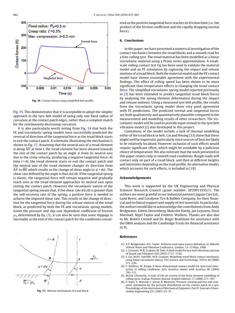
of the same radius Rd. From the measurement in Fig. 8, the radius ofthe tyre belt at the contact patch edges is about 0.5 m. The resultsof a simulation with Rd = 0.5 m and = 0.17 m are shown in Fig. 16.Predictions are close to those using the actual measured profile,
Fig. 14. Comparison of modelling results using measured tyre belt profile.
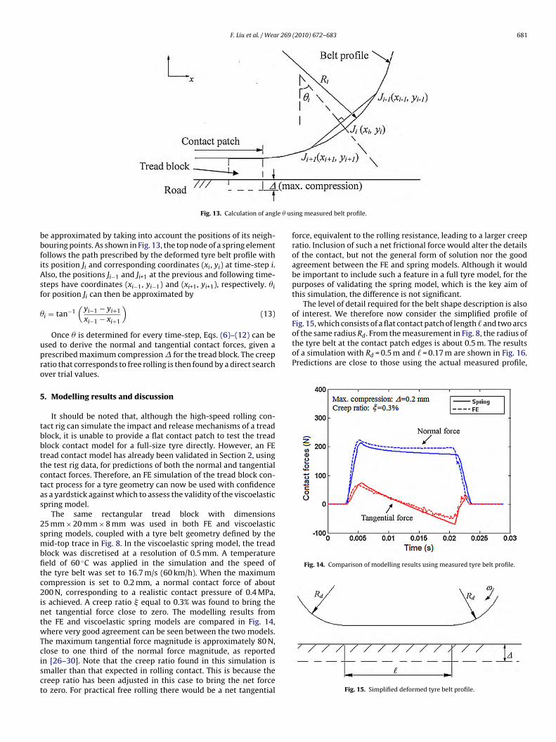
Fig. 13. Calculation of ang
e approximated by taking into account the positions of its neigh-ouring points. As shown in Fig. 13, the top node of a spring elementollows the path prescribed by the deformed tyre belt profile withts position Ji and corresponding coordinates (xi, yi) at time-step i.lso, the positions Ji−1 and Ji+1 at the previous and following time-teps have coordinates (xi−1, yi−1) and (xi+1, yi+1), respectively. �ior position Ji can then be approximated by
i = tan−1(yi−1 − yi+1
xi−1 − xi+1
)(13)
Once � is determined for every time-step, Eqs. (6)–(12) can besed to derive the normal and tangential contact forces, given arescribed maximum compression� for the tread block. The creepatio that corresponds to free rolling is then found by a direct searchver trial values.
. Modelling results and discussion
It should be noted that, although the high-speed rolling con-act rig can simulate the impact and release mechanisms of a treadlock, it is unable to provide a flat contact patch to test the treadlock contact model for a full-size tyre directly. However, an FEread contact model has already been validated in Section 2, usinghe test rig data, for predictions of both the normal and tangentialontact forces. Therefore, an FE simulation of the tread block con-act process for a tyre geometry can now be used with confidences a yardstick against which to assess the validity of the viscoelasticpring model.
The same rectangular tread block with dimensions5 mm × 20 mm × 8 mm was used in both FE and viscoelasticpring models, coupled with a tyre belt geometry defined by theid-top trace in Fig. 8. In the viscoelastic spring model, the tread
lock was discretised at a resolution of 0.5 mm. A temperatureeld of 60 ◦C was applied in the simulation and the speed ofhe tyre belt was set to 16.7 m/s (60 km/h). When the maximumompression is set to 0.2 mm, a normal contact force of about00 N, corresponding to a realistic contact pressure of 0.4 MPa,
s achieved. A creep ratio equal to 0.3% was found to bring theet tangential force close to zero. The modelling results fromhe FE and viscoelastic spring models are compared in Fig. 14,here very good agreement can be seen between the two models.
he maximum tangential force magnitude is approximately 80 N,
lose to one third of the normal force magnitude, as reportedn [26–30]. Note that the creep ratio found in this simulation ismaller than that expected in rolling contact. This is because thereep ratio has been adjusted in this case to bring the net forceo zero. For practical free rolling there would be a net tangentialing measured belt profile.
force, equivalent to the rolling resistance, leading to a larger creepratio. Inclusion of such a net frictional force would alter the detailsof the contact, but not the general form of solution nor the goodagreement between the FE and spring models. Although it wouldbe important to include such a feature in a full tyre model, for thepurposes of validating the spring model, which is the key aim ofthis simulation, the difference is not significant.
The level of detail required for the belt shape description is alsoof interest. We therefore now consider the simplified profile ofFig. 15, which consists of a flat contact patch of length and two arcs
Fig. 15. Simplified deformed tyre belt profile.
682 F. Liu et al. / Wear 269
Facf
FrtsitdttAsirettatbG�i
Fig. 16. Contact forces using simplified belt profile.
ig. 15. This demonstrates that it is acceptable to adopt the simplerpproach in the tyre belt model of using only one fixed radius ofurvature at the contact patch edges, rather than a complete matchor the continuously decreasing curvature.
It is also particularly worth noting from Fig. 14 that both theE and viscoelastic spring models have successfully predicted theeversal of direction of the tangential force as the tread block startso exit the contact patch. A schematic illustrating the mechanism ishown in Fig. 17. Assuming that the neutral axis of a tread elements along AA′ at time t, the tread element has been sheared towardshe exit of the contact patch by an angle from its neutral axisue to the creep velocity, producing a negative tangential force. Atime t + dt, the tread element starts to exit the contact patch andhe neutral axis of the tread element changes its direction fromA′ to BB′ which results in the change of shear angle to + d . Thehear rate defined by the angle is thus d /dt. If the tangential springs elastic, the tangential force will remain negative and graduallyeach zero as the tread element approaches its neutral axis uponxiting the contact patch. However the viscoelastic nature of theangential spring means that, if the shear rate d /dt is greater thanhe self-recovery rate of the spring, a positive force is needed tochieve the imposed shear rate. This results in the change of direc-ion for the tangential force during the release motion of the tread
lock, as predicted by both the FE and viscoelastic spring models.iven the pressure and slip-rate dependent coefficient of frictionk determined by Eq. (5), it can also be seen that some slippage isnevitable at the end of the contact patch for the conditions consid-
Fig. 17. Release mechanism of tread block.
(2010) 672–683
ered as the positive tangential force reaches its friction limit (i.e. theproduct of the friction coefficient and the rapidly dropping normalforce).
6. Conclusions
In this paper, we have presented a numerical investigation of thecontact mechanics between the tread blocks and a smooth road fora free-rolling tyre. The tread material has been modelled as a linearviscoelastic material using a Prony series approximation. A small-scale rolling contact test rig has been used to validate the materialmodel and an FE simulation by capturing the impact and releasemotions of a tread block. Both the material model and the FE contactmodel have shown reasonable agreement with the experimentalfindings. The effect of rolling speed has been shown to be moresignificant than temperature effects in changing the tread contactforce. The simplified viscoelastic spring model reported previouslyin [3] has been extended to predict tangential tread block forcesby analysing the spring element deformation during the impactand release motions. Using a measured tyre belt profile, the resultsfrom the viscoelastic spring model show very good agreementwith FE predictions. The predicted normal and tangential forcesare both qualitatively and quantitatively plausible compared to themeasurement and modelling results of other researchers. The vis-coelastic model will be used to provide input stimuli to the tyre beltvibration model [2] also developed in this project.
Limitations of the model include a lack of thermal modellingeither of the tread block or belt; Lin and Hwang [33] show that thesemight well be important, particularly since sources of heat are likelyto be relatively localised. However inclusion of such effects wouldrequire significant effort, which might be avoidable by a judiciouschoice of temperature. We also reiterate that the work presented inthis paper relates only to smooth road conditions. Rough roads willcontact only on part of a tread block, and then at different heightsand intensities depending on the road profile. An alternative model,which accounts for such effects, is included in [18].
Acknowledgements
This work is supported by the UK Engineering and PhysicalSciences Research Council (grant number: EP/D011035/1). Theauthors are most grateful to our industrial partners Jaguar Cars Ltd.,Land Rover, and Goodyear Tire & Rubber Company, for their finan-cial and technical support and supply of test materials. In particular,the authors would like to acknowledge the contributions from AndyBridgwater, Edwin Deerenberg, Malcolm Hardy, Jan Leyssens, DaveMarshall, Nigel Taylor and Frederic Wullens. Thanks are also dueto Mr. Robert Cornell and Dr. Roger Bradshaw for assistance withthe DMA analysis and the Cambridge Trusts for financial assistanceto FL.
References
[1] A.P. Bridgewater, N.C. Taylor, Airborne road noise source definition, in: IMechEVehicle Noise and Vibration Conference, London, 12–13 May, 1998.
[2] C. Lecomte, W.R. Graham, M. Dale, A shell model for tyre belt vibrations, Journalof Sound and Vibration 329 (2010) 1717–1742.
[3] F. Liu, M.P.F. Sutcliffe, W.R. Graham, Modelling tread block contact mechanicsusing linear viscoelastic theory, Tire Science and Technology, TSTCA 36 (2008)211–226.
[4] F. Wullens, W. Kropp, A three-dimensional contact model for tyre/road inter-action in rolling conditions, Acta Acustica united with Acustica 90 (2004)702–711.
[5] M.H.R. Ghoreishy, A state of the art review of the finite element modelling ofrolling tyres, Iranian Polymer Journal (English Edition) 17 (2008) 571–597.
[6] P. Sujin, Y. Wansuk, C. Jinrae, K. Beomsoo, Pressure-sensing pad test and com-puter simulation for the pressure distribution on the contact patch of a tyre,Proceedings of the Institution of Mechanical Engineers. Part D: Journal of Auto-mobile Engineering 221 (2007) 25–31.
r 269
[
[
[
[
[
[
[
[
[
[
[
[
[
[[
[
[
[
[
[
[
[
F. Liu et al. / Wea
[7] W. Hall, J.T. Mottram, R.P. Jones, Finite element simulation of a rolling automo-bile tyre to understand its transient macroscopic behaviour, Proceedings of theInstitution of Mechanical Engineers. Part D: Journal of Automobile Engineering218 (2004) 1393–1408.
[8] J. Cesbron, F. Anfosso-Lédée, D. Duhamel, H. PingYin, D. Le Houedec, Experimen-tal study of tyre/road contact forces in rolling conditions for noise prediction,Journal of Sound and Vibration 320 (2009) 125–144.
[9] G.D. Dean, J.C. Duncan, A.F. Johnson, Determination of non-linear dynamicproperties of carbon-filled rubbers, Polymer Testing 4 (1984) 225–249.
10] L. Boltzmann, Zur Theorie der Elastischen Nachwirkung, Annalen der Physikund Chemie 27 (1876) 624–654.
11] K.A. Grosch, The relation between the friction and visco-elastic properties ofrubber, Proceedings of the Royal of Society London. Series A 274 (1963) 21–39.
12] W. Kropp, Structure-borne sound on a smooth tyre, Applied Acoustics 26 (1989)181–192.
13] P. Andersson, K. Larsson, F. Wullens, W. Kropp, High frequency dynamicbehaviour of smooth and patterned passenger car tyres, Acta Acustica unitedwith Acustica 90 (2004) 445–456.
14] J. Holtschulze, H. Goertz, T. Hüsemann, A simplified tyre model for intelligenttyres, Vehicle System Dynamics 43 (Suppl.) (2005) 305–316.
15] M. Brinkmeier, U. Nackenhorst, Computational investigation on dynamics oftires rolling on rough roads, Tire Science and Technology, TSTCA 37 (2009)47–59.
16] R.A. Graf, C.-Y. Kuo, A.P. Dowling, W.R. Graham, A mathematical modelof tyre–road noise, IMechE Conference Transactions (2002) 133–142,VC605/015/2002.
17] P.B.A. Andersson, W. Kropp, Time domain contact model for tyre/road interac-
tion including nonlinear contact stiffness due to small-scale roughness, Journalof Sound and Vibration 318 (2008) 296–312.18] F. Liu, Tribology of Free-rolling Tyres, PhD thesis, Cambridge University Engi-neering Department, 2008.
19] M.G. Pottinger, The three-dimensional contact patch stress field of solid andpneumatic tires, Tire Science and Technology, TSTCA 20 (1992) 3–32.
[
[
(2010) 672–683 683
20] S.O. Oyadiji, How to analyse the static and dynamic responses of viscoelasticcomponents, NAFEMS (2004) 7–11.
21] R.D. Bradshaw, L.C. Brinson, A sign control method for fitting and inter-converting material functions for linearly viscoelastic solids, Mechanics ofTime-dependent Materials 1 (1997) 1385–2000.
22] M. Klüppel, Evaluation of viscoelastic master curves of filled elastomers andapplications to fracture mechanics, Journal of Physics Condensed Matter 21(2009) 1–10.
23] W. Gnörich, Goodyear Luxembourg Technical Centre, personal communication.24] ABAQUS/Explicit, version 6.5, Hibbet Karlsson and Sorenson Inc., 2005 (Now
Dassault Systemès).25] T. Huemer, W.N. Liu, J. Eberhardsteiner, H.A. Mang, A 3D finite element formula-
tion describing the frictional behaviour of rubber on ice and concrete surfaces,Engineering Computations 18 (2001) 417–436.
26] N. Seitz, A.W. Hussmann, Forces and displacement in contact area of free rollingtires, ASME transactions, Paper 710626, 1973.
27] Force and Acceleration Measurement Results for a Simple Tread Block, Releasedby Dunlop Tyres Limited (Now Goodyear Tire and Rubber Company) to Cam-bridge University Engineering Department During URGENT Project, 1999.
28] S.A. Lippmann, K.L. Oblizajek, The distribution of stress between the tread andthe road for freely rolling tires, ASME transactions, Paper 740072, 1976.
29] M. Berger, Kinematics of a rolling tire and its application to tire performance,Journal of Applied Polymer Science 2 (1959) 174–180.
30] W.W. Klingbeil, H.W.H. Witt, Some consequences of Coulomb friction in mod-elling longitudinal traction, Tire Science and Technology, TSTCA 18 (1990)13–65.
31] R. Matsuzaki, A. Todoroki, Wireless strain monitoring of tires using electrical
capacitance changes with an oscillating circuit, Sensors and Actuators, Part A119 (2005) 323–331.32] Yan, Micro/Nano-electro-mechanical Resonators for Signal Processing, PhDthesis, Cambridge University Engineering Department, 2007, pp. 58–59.
33] Y.-J. Lin, S.-J. Hwang, Temperature prediction of rolling tires by computer sim-ulation, Mathematics and Computers in Simulation 67 (2004) 235–249.