Precision Irrigation Controller Technical Speci˜cations
24
Precision Irrigation Controller: Quick Start Guide
Transcript of Precision Irrigation Controller Technical Speci˜cations

Precision Irrigation Controller: Quick Start Guide

1
2.4 GHzWi-Fi & Local RF:1 Amp Fuse Per Output
24 VAC3.3v Signal
Output:
12 VDC PowerGrowlink TDR Soil Moisture Sensor(s)Environmental Sensor Input(s):
24 VACPower Input:
Precision Irrigation Controller Technical Speci�cations

2
Remote Access - Manage and monitor your climate and substrate remotely and quickly adjust strategies from
a smartphone, tablet, or laptop - anytime, anywhere.
TDR Soil Moisture Sensors - Cutting-edge, digital, true time-domain re�ectometer (TDR) soil moisture sensors
accurately measure soil moisture, EC, and temperature.
OTA Updates - Our controllers regularly receive over-the-air software updates that add new features and
enhance existing ones over Wi-Fi.
Alerts - Stay informed on all active and historical alerts from your Growlink systems.
Fanatical Support - Free support from a Growlink specialist (during o�ce hours).
Features

3
22Warranty and EULA
19 - 21Troubleshooting
16 - 18Programming Rules, Triggers, and Timers
Crop Steering Basics 15
14Crop Steering With Irrigation
13Module Wiring
12Controller and Sensor Placement
6 - 11Quick Set Up Guide
5Controller and Sensor Dimensions
4What’s In The Box
3Contents
2Features
Precision Irrigation Controller Technical Speci�cations 1
Contents

4
Precision Irrigation Controller
Mounting Hardware
Quick Start Guide
TDR (VWC, EC, Temperature) Sensor(s)
24 VAC Power Supply
What’s In The Box

5 2.08”
6.32”
2.32”
4”
Depth = .59”
Sensor
Depth = 1 3/4”
7”
10”
Controller
Controller and Sensor Dimensions

6
2. Open the Growlink app and tap Create Account.
3. After creating an account, log into the app.
1. Download the Growlink app from the Apple App Store, or Google Play Store.
Quick Set Up Guide

7
4. Tap on the icon in the top right corner and tap Connect to Controller.
If it is your �rst time creating an account, it will automatically promptyou to Set Up A New Controller.
Quick Set Up Guide

8
For Android Users: Wait for a list of available controllers to populate in the Growlink app, then select the controller matching the SSID printed on the controller.
5. For iPHONE users: When the Connect to Controller Hub window appears, open the Wi-Fi settings on your phone and select the SSID of the controller you are connecting (i.e., Growlink-4YJM7T). Wait for the to appear, then go back to the Growlink app.
Quick Set Up Guide

9
6. From the Set Up Controller Hub window, tap Next.
7. Select your local Wi-Fi network and enter your network password. Then tap Set Access Point.
Quick Set Up Guide

10
8. Name your controller (i.e., Flower Room Irrigation).
Quick Set Up Guide

11
9. After controller registration, tap on Go To Settings.
From the Controller Pro�le page, you can set the country you are in,time zone, Day Start & Day End (Lights On & Lights O� ). Tap Save,and you will be returned to the Main Dashboard.
Quick Set Up Guide

12
* The example shown is for placement of sensor for a 6” x 6” x 6” Rockwool cube. Please visit our resource guide for proper placement in other commonly used substrates.
Probes should be fullyemerged in cube and level on
a horizontal orientation.
1”
Recommended placement for substratesensors in 6” x 6” Rockwool cubes is
approximately 1” from bottom ofcube, centered in the media in
a horizontal orientation.
1”
Install Precision Irrigation Controller in a central location according to
where sensors will be placed.
Controller
Probe Wires
Controller and Sensor Placement

13
24 VAC Irrigation Valve
Sensor Inputs (Up to Four Inputs)24 VAC Power Input
Module Wiring

14
NIGHTDAYNIGHT
Flushing:
WC
WC
Manage plant growth by adjusting environmental factors and/or irrigation to encourage a crop’s desired outcome. Changing environmental conditions allows the in�uence of growth toward the desired growth stage, typically vegetative or generative.

15
* Source: T R Y M™ - Growers Guide to Crop Steering
* Vegetative Irrigation Strategy
* Generative Irrigation Strategy
The following ranges are examples of conditions that couldinduce generative growth.
Actual conditions will vary by grow environment and cultivar. It’scritical that you adapt your climate and irrigation strategy to yourspeci�c environment and genetics by combiningexperimentation of steering actions with frequent crop registration.
Shot Size 1 - 3 % of Substrate Volume10 - 15%72 - 78 ˚F2 - 4 dS / m55 - 70%6 - 9 (Lights On)
Dry BackSubstrate TemperatureElectrical ConnectivityWater Content (VWC)Irrigation Frequency
Shot Size 4 - 8% of Substrate Volume15 - 30%68 - 76 ˚F 5 - 12 dS / m25 - 70%3 - 9 (Lights On)
Dry BackSubstrate TemperatureElectrical ConnectivityWater Content (VWC)Irrigation Frequency
The following ranges are examples of conditions that couldinduce vegetative growth.
Crop Steering Basics

16
1
2
3
4
5
6
7
1. From this menu, name your program (1)
2. Choose which Sensor(s) your program will be based on (2)
3. Select which Devices will be activated (3)
4. Input Lights On Time (additional Dry-Back % time begins) (4)
5. Set Irrigation End Time (Dry-Back period begins) (5)
6. Designate Ramp Up Target VWC% (6)
7. Designate Dry-Back Target VWC% (7)
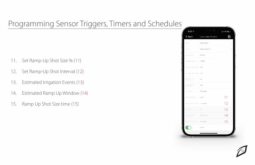
Programming Sensor Triggers, Timers and SchedulesTo Set Parameters For Crop SteeringSelect controller from the:Dashboard > Rules > Crop Steering > Add Crop Steering Program

17
10
9
8
8. Designate Additional Dry-Back % Amount (8)
9. Set Maintenance Dry-Back Amount (9)
10. Set 1% Shot Size time (10) This number represents how many seconds of irrigation it takes to gain 1% VWC. To �gure out this value:
1. Start with your medium at roughly 40% to 50% VWC. Write down your starting VWC. 2. Activate your irrigation and start a stopwatch. Wait 2-5 minutes, then turn your irrigation o� and stop the stopwatch. Wait a few more minutes for the reading to stabilize. Now write down your ending VWC. 3. 1% Shot Size = (Stopwatch Time In Seconds) / (Ending VWC - Starting VWC). For example, if you went from 40% to 55% VWC in 180 seconds, then your "1% shot size" = 180 / (55-40) = 12 seconds.
Programming Sensor Triggers, Timers and Schedules
18
11
12
13
14
15
11. Set Ramp-Up Shot Size % (11)
12. Set Ramp-Up Shot Interval (12)
13. Estimated Irrigation Events (13)
14. Estimated Ramp Up Window (14)
15. Ramp Up Shot Size time (15)
Programming Sensor Triggers, Timers and Schedules
19
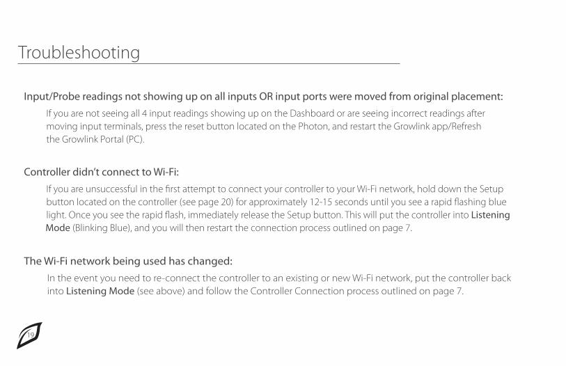
The Wi-Fi network being used has changed: In the event you need to re-connect the controller to an existing or new Wi-Fi network, put the controller back into Listening Mode (see above) and follow the Controller Connection process outlined on page 7.
Controller didn’t connect to Wi-Fi: If you are unsuccessful in the �rst attempt to connect your controller to your Wi-Fi network, hold down the Setup button located on the controller (see page 20) for approximately 12-15 seconds until you see a rapid �ashing blue light. Once you see the rapid �ash, immediately release the Setup button. This will put the controller into Listening Mode (Blinking Blue), and you will then restart the connection process outlined on page 7.
Input/Probe readings not showing up on all inputs OR input ports were moved from original placement: If you are not seeing all 4 input readings showing up on the Dashboard or are seeing incorrect readings after moving input terminals, press the reset button located on the Photon, and restart the Growlink app/Refresh the Growlink Portal (PC).
Troubleshooting

20
Troubleshooting

21
Controller LED Status Light Color Codes During initial setup of a device and operation, these are the usual LED speci�cations:
• White Pulse: Start-up (happens when the Growlink is �rst powered on or when it’s reset). • Flashing Blue: Listening Mode, waiting for Wi-Fi credentials. • Flashing Green: Connecting to Wi-Fi network (If �ashing green occurs after the controller has been connected previously, this means you have lost connection, or your network may have gone o�ine). • Breathing Green: Connected to Wi-Fi network. • Blinking Green/Rapid Flashing Cyan: If controller is not reachable from the Growlink app or Portal, this could mean there is a weak/lost connection to local network. Check connection and/or move Wi-Fi access point closer to controller. • Flashing Cyan: Connecting to Growlink Device Cloud (Connecting to the network, but not necessarily connected to the internet yet). • High-speed Flashing Cyan: Growlink Device Cloud handshake. • Breathing Cyan: Connected to Growlink Device Cloud. • Flashing Magenta: Receiving new �rmware update over-the-air (OTA). • Breathing Magenta: Safe Mode, connected to Particle Device Cloud, but user �rmware not running.
Troubleshooting

22
End User License AgreementGrowlink Standard Warranty
Warranty and EULA