
Precast Prestressed Concrete Panel Subdecks in Skewed...
40
•••• • Precast Prestressed Concrete Panel Subdecks in Skewed Bridges ' Interim Report by Robert E. Abendroth Iowa Highway Research Board and Highway Division Iowa Department of Transportation January 10, 1990 · '· en ineering ,.researc institute iowa state university This Is a preprint of a paper intended for publication In a journal or proceedings. Since changes may be made be!ore publication. ihis preprint is ·made available with the understanding that ii will not be cited or reproduced without the permission of the author.
Transcript of Precast Prestressed Concrete Panel Subdecks in Skewed...

••••
•
Precast Prestressed Concrete Panel Subdecks
in Skewed Bridges
' Interim Report
by
Robert E. Abendroth
Iowa Highway Research Board and
Highway Division Iowa Department of Transportation
January 10, 1990
· '· .~!1 en ineering ,.researc institute
iowa state university This Is a preprint of a paper intended for publication In a journal or proceedings. Since changes may be made be!ore publication. ihis preprint is
·made available with the understanding that ii will not be cited or reproduced without the permission of the author.

~--
•
•
--·
i
Table of Contents
~bstract
1. Introduction
2. Task 1 - Literature Review and Surveys
2 .1. 2. 2.
Background Questionnaires 2.2.1. Design Agency Questionnaire 2.2.2. Precaster Questionnaire
3. Task 2 - Field Inspections
3 .1. 3. 2. 3. 3.
Bridge Descriptions Inspection Results Inspection Recommendations
4. Task 3 - Experimental Program
4.1. 4.2. 4.3. 4.4. l1. 5. 4.6.
Specimens Tests Panels Test Frame Instrumentation Frame Abutment Supports
5. Task 4 - Analytical Studies
5.1. Panel Model 5.2. Bridge Deck Model
6. Experimental and Analytical Results
6 .1. 6.2.
Strand Development Length Bridge Deck Behavior for Interior Panel Configuration
7 . Fu tu re W9rlc.
7 .1. 7. 2.
Experimental Analytical
8. Acknowledgements
Page
ii
1
2
2 2 3 7
11
11 12 13
14
14 15 16 17 17 17.
19
19 19
23
23 29
36
36 36
37

•
•
•
•
ii
Abstract
Precast prestressed concrete panels have been used in bridge deck
construction in Iowa and many other states. To investigate the performance of
these panels at abutment or pier diaphragm locations for bridges with various
skew angles, a research program involving both analytical and experimental
aspects, is being conducted. This interim report presents the status of the
research with respect to four tasks. Task 1 which involves a literature review
and two surveys is essentially complete. Task 2 which involved field
investigations of three Iowa bridges containing precast panel subdecks has been
completed. Based on the findings of these investigations, future inspections
are recommended to evaluate potential panel deterioration due to possible
corrosion of the prestressed strands. Task 3 is the experimental program which
has been established to monitor the behavior of five configurations of full scale··
composite deck slabs. Three dimensional test and instrumentation frameworks have
been constructed to load and monitor the slab specimens. The first slab
configuration representing an interior panel condition is being tested and
preliminary results are presented for one of these tests in this interim report.
Task 4 involves the analytical investigation of the experimental specimens.
Finite element methods are being applied to analytically predict the behavior
of the test specimens. The first test configuration of the interior panel
condition has been analyzed for the same loads used in the laboratory, and the
results are presented herein. Very good correlation between the analytical and
experimental results has occurred .

•
•
•
1
1. Introduction
This interim report has been written to provide the status of the research
project entitled "Precast Prestressed Concrete Panel Subdecks in Skewed Bridges".
As described in the research proposal, precast prestressed concrete panels are
permanent forms that have been used for casting bridge decks. These slab panels
eliminate the need for using conventional temporary formwork between the bridge
girders. A reinforced concrete slab is cast on top of the panels forming a'
composite system with the prestressed panels to resist the applied highway
loadings. The panels replace the bottom portion of a conventional full depth
reinforced concrete deck, including the bottom layer of reinforcement in both
the longitudinal and transverse directions. The total thicknesses of a composite
slab and a conventional full depth cast-in-place slab are normally the same.
The research proposal identified four tasks. Task 1 involves a review of
the literature and surveys of design agencies and panel producers. Field
investigations of three bridges constructed with precast panel subdecks in Iowa
are contained in Task 2. Task 3 involves an extensive experimental testing
program of full scale specimens. Analytical investigations are contained in Task
4. The work completed to date and future efforts for each of these tasks are
discussed in the following sections of this interim report .

f' 2
2. Task 1 - Literature Review and Surveys
• 2.1. Background
•
•
The literature review has been essentially completed. Many articles have
been located that address the use of precast prestressed concrete panels as
permanent forms in bridge deck construction. These articles have discussed a
variety of issues including reflective cracking in the cast-in-place topping slab
at the panel joints, bond between the panels and the reinforced concrete slab,
panel bearing, prestress strand extensions beyond the ends of the panels, strand
transfer and development lengths, continuity conditions for the panels at the
girders, and flexural and shear strengths for composite slabs whose supports
occur only at the ends of the prestressed panels. The literature review to date
has not revealed any studies that address the behavior of these slab systems at
locations adjacent to abutment or pier diaphragms on non-skewed or skewed
bridges .. At these deck locations the ends of a precast panel are supported by
the bridge girders and a longitudinal edge of the panel is supported by ·a
diaphragm.
2.2. Questionnaires
Survey questionnaires were developed and distributed to both design
agencies and precast prestressed concrete producers who are members of the
Prestressed Concrete Institute. The survey that was sent to the 50 state
departments of transportation, District of Columbia, tollway authorities, two
United States provinces, and eight Canadian provinces contained nine parts and.
asked 83 questions. This questionnaire addressed topics related to general
bridge geometry and conditions, general panel geometry and conditions, panel
bearing details, pres tressing strand description and conditions, design criteria,'
economy, experiences with panel usage, and panel details and specifications .
The survey that was sent to 192 manufacturers in the United States and Canada

.. 3
contained ten parts and asked 80 questions. This questionnaire addressed topics
• related to the producers background, general bridge panel conditions and
geometry, bridge panel bearing details, pres tressing strand conditions and
description for bridge panels, design criteria, economy, inspection, experience·
with panel usage, and panel details and specifications. Even though both surveys
were extensive, the vast majority of the questions were multiple cho.ice type.
Seventy-one out of 121 questionnaires that were sent to the design agencies were
returned and of those, 29 or about 41% stated that they allow or have allowed
the use of precast panels in bridge deck construction. Seventy-three out of 192
questionnaires that were sent to the precast manufacturers were returned and of
those, 27 or about 40% stated that they have produced precast panels for bridges.
2.2.1. Design Agency Questionnaire
Some of the results from the questionnaire returned by the design agencies
are given in Table 2.1. The total of the responses to a given question may not
equal 29, since multiple responses may have been given or the question may have
been skipped by some respondents.
Table 2.1. Selected Survey Results from Design Agencies
The number in the parenthesis ( ) represents the number of design agencies having that particular answer.
1-3. Is your state or agency currently using or specifying panels for bridge deck construction?
(16) Yes (13) No
1-9. What type of panel support is provided for typical panels spanning perpendicular to the bridge span?
• (1) (16) (3) (9) (2)
Panels are not used to span in this direction Precast prestressed concrete girders only Steel girders only Either precast concrete or steel girders Other

•
•
•
4
II-3 . Minimum panel thickness used:
(1) Not specified (8) 3 in. (3) 4 in. (4) 2~ in. (11) 3~ in. (1) Other
II-5. Panel construction at skewed abutment or pier locations:
(8) Panels not used at these locations (4) Panels sawn to match the skew only (2) Panels cast to match the skew only (12) ·Panels sawn or cast to match the skew (3) Other
III-7. Permanent bearing material used to support panels:
(1) Not specified (7) Continuous fiberboard, neoprene, polystyrene, or similar
material only (20) Continuous mortar, grout, or concrete bed only (0) Steel shims at panel corners only (1) Any of the above (3) Other
IV-1. Total diameter of the strand that is used most often:
(0) (0)
1/4 in. 5/16 in.
(23) (2)
3/8 in. 7/16 in.
IV-6. Are strand extensions used?
(18) Always (2) Sometimes
(3) 1/2 in. (0) Other
(8) Never
V-17. Is the bridge deck designed as a continuous span across the girders when panels are used?
(24) Always (3) Sometimes (1) Never
V-21. Is two-way plate action considered in the design of the deck when the panels are supported along three edges?
(10) Three edge panel support not permitted (1) Yes (16) No
V-22. Is fatigue considered in the design of the deck when panels are used?
(1) Yes (26) No
VI-1. Have cost effectiveness studies even been performed to evaluate the economical advantages of using panels instead of full depth bridge deck?
(5) .Yes (23) No
•
•
•
VI-2.
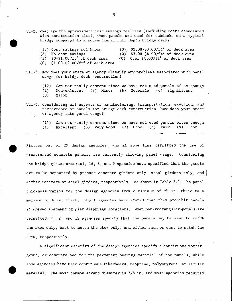
5
What are the approximate cost savings realized (including costs associated with construction time), when panels are used for subdecks on a typical bridge compared to a conventional full depth bridge deck?
(18) (6) (3) (0)
Cost savings not known No cost savings $0-$1.00/ft2 of deck area $1.00-$2.00/ft2 of deck area
(0) (0) (0)
$2.00-$3.00/ft2 of deck area $3.00-$4.00/ft2 of deck area Over $4.00/ft2 of deck area
VII-5. How does your state or agency classify any problems associated with panel usage for bridge deck construction?
(12) (1) (0)
·can not really Non-existent Major
comment since we have not used panels often enough (7) Minor (6) Moderate (6) Significant
VII-6. Considering all aspects of manufacturing, transportation, erection, and performance of panels for bridge deck construction, how does your state or agency rate panel usage?
(11) Can not really comment since we have not used panels often enough (1) Excellent (3) Very Good (7) Good (5) Fair (5) Poor
Sixteen out of 29 design agencies, who at some time permitted the use of
prestressed concrete panels, are currently allowing panel usage. Considering
the bridge girder material, 16, 3, and 9 agencies have specified that the panels
are to be supported by pr.ecast concrete girders only, steel girders only, and
either concrete or steel girders, respectively. As shown in Table 2 .1, the panel
thickness varies for the design agencies from a minimum of 2~ in. thick to a
maximum of 4 in. thick. Eight agencies have stated that they prohibit panels
at skewed abutment or pier diaphragm locations. When non-rectangular panels are
permitted, 4, 2, and 12 agencies specify that the panels may be sawn to match
the skew only, cast to match the skew only, and either sawn or cast to match the
skew, respectively.
A significant majority of the design agencies specify a continuous mortar,
grout, or concrete bed for the permanent bearing material of the panels, while
some agencies have used continuous fiberboard, neoprene, polystyrene, or similar
material. The most common strand diameter is 3/8 in. and most agencies required

•
•
strand extensions. Regarding the behavior of the composite slab system, most
agencies assume that the bridge deck has continuous spans across the bridge.
girders and that fatigue stresses and strains are not considered. Two-way plate
bending is considered only by one design agency and neglected by 16 agencies when
panels are supported along three edges. Ten agencies do not permit panels to
be supported along three edges.
The survey revealed that five design agencies have performed some form of
an economical analysis to evaluate any economical advantages of using panels
instead of a conventional full depth reinforced concrete slab. When asked to
place an approximate dollar value on any savings, all of the design agencies
'responded that the cost savings were unknown or less than $1. OO/ft2 of the bridge
deck area.
Each design agency was asked to classify any problems associated with .
precast panel usage for bridge deck construction. No agency thought that major
problems existed with the panels; however, 12 agencies categorized problems as
either moderate or significant, while 8 agencies classify problems as either non-
existent or minor. Another 12 design agencies responded that they could not
really comment since they had not specified panels often enough. Question VII-
6 on the survey asked the respondent to consider all aspects of manufacturing,
transportation, erection, and performance of panels for bridge deck construction
and rate panel usage. Ten agencies gave panel usage only a fair or poor rating
and 11 agencies gave the panels an excellent, very good, or good rating. Another
11 agencies stated that they could not really comment since they had not used
panels often enough.
Standard details and specifications for precast panel subdecks have been
provided by many of the design agencies that have specified panels for bridge
• deck construction.

~ 7
2.2.2. Precaster Questionnaire
• Some of the results from the questionnaires returned by the manufacturers
•
•
of precast prestressed concrete panels are given in Table 2.2. The total of the
responses to a given question may not equal 27, since multiple responses may have
been given or a question may have been skipped by some respondents.
Table 2.2. Selected Survey Results from Panel Producers
The number in the parenthesis ( ) represents the number of precastors having that particular answer.
I- 3. Has your company produced or submitted a bid to produce panels for a bridge project with the last two years?
(20) Yes (7) No
II-10. Top slab roughness and projections (not including lifting hooks):
(0) Smooth finish without bar projections (0) Smooth finish with U-shaped bars or dowels (3) Broom finish without bar projections (1) Broom finish with U-shaped bars or dowels (14) Raked finish without bar projections (17) Raked finish with U-shaped bars or dowels (2) Other
11-11. What is the direction of the raked depression with respect to the panel span?
(1) Raked depression not used (6) Parallel to panel span only (17) Transverse to panel span only (1) Both parallel and transverse to the panel span (2) Diagonal to panel span (0) Other
II-23. Is additional steel provided in the panel ends to prevent splitting due to bond transfer:
(8) Always (8) Sometimes (11) Never
111-1. Temporary bearing material used to support panels:
(2) (3) (18) (2)
Temporary bearing material not used Unknown Fiberboard, neoprene, polystyrene, or similar material only Mortar, grout or concrete bed only

~' 8
•
•
•
(2) Steel shims only (2) Other
III-6. What is the minimum length of permanent bearing Pli,rallel to the panel span?
(3) .Unknown (6) 1 in.
(7) l~ in. (3) 2 in.
(3) 2~ in. (4) Other
IV-12. What method is used to release the bridge panel prestressing .strands?
(20) (6) (3)
Acetylene torches Abrasive: saw blades Wire (bolt) cutters
(2) · Slow release of hydraulic pressure • (0) Other
VII-2. Does the state or agency for which your company is casting panels have a rep.resentative at your plant to observe strand detensioning,. forin stripping, and panel handling and storage? ·
(1) Not their responsibility (19) Always (6) Sometimes ·(0) Never
VII-3. Does your company send a representative to the bridge jobsite to inspect the panels after erection for cracks and proper bearing?
(5) Not our responsibility (5) Always (12) Sometimes (4) Never·
VIII-1. Which of the following items of panel damage has your company directly experienced more than just a few times or occasionally?
(4) Can not really comment since we have not cast panels often enough (6) Have not experienced any problems (8) Broken corners (9) Spalled or chipped edges (9) Cracking parallel to strands along a significant portion of the
panel length (10) Cracking parallel to strands neaF the ends of the panel only (2) Cracking transverse to the strands near panel midspan (3) Diagonal cracks across panel surface (1) Strand slippage (4) Skew panels are difficult to detension properly (0) Other
VIII-6. Which of the following casting techniques has your company established to minimize problems in panel fabrication?
(4) Can not really comment since we have not cast panels often enough (4) Provide strand tie downs along prestress bed length (10) Clean out header strand slots after each casting (19) Allow for. concrete preset prior to heat application for accelerated
(11) (14) (2) (2)
curing Institute special strand cutting sequence Provide steel headers Allow strands to oxidize by exposure to the weather for a few days Increase concrete release strength above minimum specified

•
•
(4) (13) (0) (2) (1)
9
Increase concrete ultimate strength above min1murn·specified Provide a reinforcing bar transverse to strand at pan.el ends Apply compressed air when stripping panels Cast panels inside a structure to avoid exposure to weather Other
VIII-8. Considering all aspects of manufacturing, transportation, erection, and performance of panels for bridge deckconstru~tion, how does. your company rate panel usage?
(1) Can not really comment since we have not cast panels often enough· (7) Excellent (7) Very Good (5) Good (3) Fair (2) Poor
Twenty of the 27 precastors who have manufactured precast panels have provided
panels or submitted a bid to provide panels for bridge projects within the last
two years, which indicates that designers and bridge contractors believe that ./
precast panels provide a viable option for bridge deck construction. Questions
II-10 and II-11 in Table 2.2 show that the treatment of the top surface'of the
precast panels to obtain composite behavior between the panels and the cast-·
in-place reinforced concrete slab varies amongst the panel producers. ,A raked
finish is most common with the direction of the raking usually transverse to
the panel span. U-shaped bars or dowels across the interface between. the. two
slabs. appear to be used about 50% of the time. To prevent splitting of the
panels during strand release, some precastors place additional steel in the ends
of the panels. As shown by Question IV-12, the majority of the panel producers
use acetylene torches to release prestressing strands. Acetylene torches applied
at a single point on a strand, abrasive saw blades, and wire cutters are all
associated with quick strand release techniques. Two producers indicated that
they release strands slowly using hydraulic pressure.
Table 2.2 lists two inspection questions (Questions VII-2 and VII-3) that
were on the survey which was sent to the manufacturers. The responses indicate
that additional inspection by both design agencies and panel producers may be
• warranted.
•
•
•
10
Experiences with panel usage were addressed in Part VIiI · of the
questionnaire. Three of the eight questions asked and the producers responses .. ·
are given in Table 2. 2. Question VIII-1 wa~ confined to panel darnage only .. The
four types of damage experienced by the most panel producers. are broken corners,
spalled or chipped edges; cracking parallel to strands along a significant·
portion of the panel length, and cracking parallel to the strands near the ends
·of the panel only. To help eliminate problems with panel manufacturing; a·
variety of production techniques have been employed by panel producers as shown
by Questions VIII-6. Those items receiving the greatest number of responses were·
clean out header strand slots after each casting, allow for concrete preset prior
to heat application for accelerated curing, institute special strand cutting
sequence, provide steel headers, and provide a reinforcirig bar t~ansverse to
strand at panel ends. The manufacturers were also asked to rate panel usage
considering all aspects of manufacturing, transportation, erection, and
performance. Five producers rated precast panel usage as fair or p_oor, while
19 '.manufacturers rated panel usage as either excelle.nt, very good or good.
Some of the manufacturers of precast concrete panels have provided
dr,awings and specifications for deck panels .

,--.. -
I i, .
•
•
11
3. Task 2 - Fleld Inspections
3.1. Bridge Descriptions
On October 19, 1989 fi~ld ·inspections o.f three Iow·a bridges located. ~in
Hardin County near Eldora, Iowa were performed. All thr.ee prestressed concrete . .
girder bridges are on the farm to· market system 'and ipvolve water cro~sings.
The first bridge inspected was Bridge No. 9066 that is located 900 ft. south of . . .
the east 1/4 corner of Section 8-87.-19 in Eldora Township of Hardin .. County over
the Iowa River. This bridge has a 30 f.t. roadway width, three spans (72 . ft. -
5 in. 81 ft. -6 in., and 72 ft. -5 in.), and no skew. The horizontal alignment
is straight and the vertical alignnient is at a 0.5% grade. The second bridge.·
inspected was Bridge No. 8401 that is located 140. ft. north of the. southwest
corner of Section 36-88-19 in Clay Township of Hardin County over Pine C:reek.
This bridge has a 28 ft. roadway width, a single 80 ft. span, and no .skew.. The
horizontal alignment is straight and the vertical alignm~nt is at a 0. 375% grade ..
The last bridge inspected was Bridge No. 7022 that is located 1320 ft. south and.
1320 ft. east center of Section 12-88-20 in Jackson Township of Hardin County:
over the Iowa River. This bridge has a 30 ft. roadway width, three spans (68
ft.-3 in., 77 ft.-6 in., and 68 ft.-3 in.), and a 30 deg. skew angle. The ..
horizontal alignment is straight and the vertical alignment is on a curve having
grades of± 1.000%.
The precast prestressed concrete panels for these bridges were cast by
Precast Concrete Operations, a Division of Wheeler Consolidated, Inc., Iowa
Falls, Iowa. The panels which span between the pres tressed girders .. and· extend.
. . along the entire length of each bridge were cast during the months of June 1983·,.
March 1983, and June 1982 for Bridge Nos. 9066, 8401, and 7022, respectively.
All three bridges have the same type of details for the precast panels. The 2lrz
• in. thick by 8 ft. wide. panels were set on 3/4 in. thick by 1 in. wide fiberboard

12
strips to permit the concrete from the topping slab to flow under the panel end.s
• for permanent bearing. The condition and extent of.the concrete beating could
not be confirmed since the detail is hidden from view. At the a~utment and pier
diaphragms, the precast panels are supported along three edges. Steel channel
intermediate diaphragms are prov~ded at approximately the girder midspan
locations. These diaphragms are attached to the precast girder webs.and do not.
support the precast panels.
3.2. Inspection Results
The condition of the precast prestressed concrete panels in each of the
three bridges is essentially the same. The slope of the grade beneath each
bridge, the height of the bridge, and the presence of the waterways prevented
inspection of the underside of the panels within the center span and many panels
• within the ends spans of the three span bridges (Bridge Nos. 9066 and 7022) and
the panels withiri about the center third of the single span bridge (~ridge No.
•
8401). Many of the inspected panels for all three bridges have single ·and
sometimes multiple hairline cracks running parallel to the panel span·. These
cracks which are located within the center half of the affected panels usually
extend along the entire panel length and occur below a prestress 'strand. Also,
for all three bridges, most of the observed panels had a slight discoloration
(darker gray color) ben_eath the strands. For Bridge No. 9066, rust discoloration
on the underside of the panels within the bridge end spans was not observed.
For Bridge No. 8401, one panel located above the steel channel intermediate.
diaphragm along the west side of the bridge has rust strains about 3 in. long
near the midspan of the panel. In addition, a diagonal crack at the southwest
corner of the second panel from the south abutment along the west side of this
bridge was observed. For Bridge No. 7022, several panels have rust discoloration
about 6 in~ to 12 in. long beneath strand locations. Two panels were observed

13
to have significant rust staining. One panel, located along the north side of
• the bridge in the west end span, is the fourth panel from the west bridge
abutment. The other panel, located along the south side of the bridge in the
east end span, is the fourth panel from the east bridge abutment.
The top surface of the cast-in-place reinforced concrete slab for all
bridges had been raked parallel to the panel span. The concrete deck on Bridge
Nos. 9066, 8401, and 7022 was completely exposed, covered entirely by a sand and
gravel layer, and partly covered by sand and gravel, respectively. The grooves
from the raking and the presence of the sand and gravel fill prevent the
observation of any reflective cracking in the topping slab.
3.3. Inspection Recommendations
Since panel cracking, discoloration, and rust strains concern the
• researchers, we recommend close inspection and documentation of the condition
of the underside of the precast prestressed concrete panels that could not be
observed in this study and reinspection at a future date of all of the panels
•
for these bridges for comparison purposes and evaluation. In addition; since
these three bridges are experiencing what appears to be initial rusting ·of
prestressing strands, the researchers recommend that an inspection program be
initiated for any other bridges containing precast panels .

14
4. Task 3 - Experimental Program
• 4.1. Specimens
As discussed in the research proposal, the experimental program involves
testing five full scale specimens. Each composite specimen contains two 2Yi in.
thick precast, prestressed panels having a 5Yi in. thick reinforced concrete
topping slab and represents a different configuration of panel support and
geometry. One specimen models a typical interior condition where the specimen
is simply supported at the ends of the panel. Four specimens will be constructed
to model the composite deck at locations adjacent to abutment or pier diaphragms,
where one of the precast panels within these specimens will be supported along
one longitudinal edge in addition to the end supports. Each of these -four
specimens will have a different skew angle (0,15,30, and·40 deg.).
The precast concrete panels are described in Sec. 4.3. The 5Yi in. thick • cast- in-place reinforced concrete slab is reinforced with a single layer of
reinforcement which has the same sizes, spacings and location as the top layer
of reinforcement specified for a conventional 8 in. thick bridge deck. No~ 5
bars, which are positioned transverse to the span of the panels are spaced 9 in ..
on center and are supported on lYi in. high individual bar chairs spaced at 3 ft.
on center in both directions. The bar chairs rest directly on the top surface
of the precast panels. No. 6 bars at 10 in. on center are positioned parallel
to the span of the panels and are directly above the No. 5 bars. All reinforcing
bars are A615 Grade 60 bars. Epoxy coated bars were not used. The concrete
cover above the No. 6 bars is about 2Yi in. The concrete for the topping slab.
is the Iowa Department of Transportation Mix No. 057 with the course aggregate
satisfying Gradation No. 5 (1 in. maximum size) and the fine aggregate satisfying
Gradation No. 1. The approximate quantities of dry materials per cubic yard of
• concrete are 710, 1413, 1413, and 291 lb of cement, fine aggregate, course

•
-------------------------------------·. ~
15
aggregate, and water, respectively. Air entrainment is 6% and the.slump should
be between 1 to 3 in. with an absolute maximum of 4 in.
4.2. Tests
· Initially, the test specimens will be subjected to a series. of static
. loads pas i tioned at various locations on the slab surface. The maximtim magnitude
for these loads are equal to an HS-20 wheel load including a.30%"impact factor.·
The 20. 8 kip load will be applied through an AASHTO wheel load footprint, having
a rectangular area equal to 160 in2 '(8 in. by 20 in.). After completion of the
static load te'sts, ultimate load tests will be perfor,med ·to establish the
flexural and shear strengths for the specimens. The ultimate flexural strength
will be established first when the wheel load footprint is positioned over the
joint between the two precast panels at the midspan of the panels; .After the
• ultimate flexural strength test has been completed, the wheel load footprint will
be repositioned to the mid-width of one of the precast panels adjacent to one
end of the panel. For this load position, an ultimate shear strength test will
•
be attempted on the same test specimen.
Instrumentation for all static and ultimate load tests . consists of
electrical resistance strain gauges to measure concrete strains on the top and
bottom of the specimens at various points along the midspan of specimens, load
cells to monitor the applied wheel loads, dial gauges to measure vertical slab
deflection at various points on the slab surface, and displacement transducers
to monitor three types of displacements. These displacements inciude vertical
slab deflection at the load position, potential strand slip· on selected
pres tressed strands, and possible end-slip between the reinforced concrete
topping slab and a precast panel at some preselected locations .

,-------------------------------
• 16
4.3. Panels
Ten precast prestressed concrete panels have been provided and delivered
to the Structural Engineering Laboratory at Iowa State University by Precast
Concrete Operations, a Division of Wheeler Consolidated, Inc., Iowa Falls, low.a.
All panels are 2~ in. thick and 7 ft. -1 in. long. The rectangular shaped panels
are 8 ft. wide and the four trapezoidal shaped vary in width along their. length.
Each of these panels is 8 ft. wide at their maximum width. The minimum widths
are 6 ft. -11.z; in., 3 ft. -10 7/8 in., and 2 ft. -0 5/8 in ... for the panels having
skew angles of 15, 30, and 40 deg., respectively. The top surface of the panels
has a raked finish that runs perpendicular to the span of the panel. All of the
panels contain sixteen 3/8 in. dia., 7 wire, 270 ksi, low relaxation pres tressing ·
strands positioned at the mid-depth of the panel. The strands, which are·spaced
at 6 in. on center, extend beyond the ends of the panels by 5 in. and by 6 in.
• along any diagonal edge. Each panel has a single layer of 6x6-W5.5xW5.5 welded
wire fabric located directly on top of the prestressing strands. The trapezoidal·
shaped panels have two No. 5 reinforcing bars placed along the diagonal edge ·Of
the panel. Some of the short strands in the trapezoidal shaped panels were
sleeved to prevent bonding with the concrete. This debonding was done to prevent
the triangular shaped corner of a panel from breaking during the detensioning
of the prestressing strands.
After the strands were prestressed to about 17.2 kips, approximately 75%
of the strand tensile strength, and before the concrete was cast; four panels
were instrumented with PML-30 polyester model strain gauges. These gauges were
wired between adjacent strands to position the gauges at the mid-depth of the
panel and midway between two strands. These gauges were used to measure concrete
strains during and after detensioning of the prestressing strands. After one
•

i L
17
day of heat curing, the concrete release strength was 4,810 psi. The 28 day
• concrete compressive strength was 7,532 psi.
4.4. Test Frame
To. resist the test loads applied to the full scale specimens, a three
dimensional structural steel frame has been designed, fabricated, and erected
on the tie-down floor in the Structural Engineering Laboratory. Based· on
allowable stresses, the frame will resist 100 kips placed anywhere within a 6
ft.-6 in. by 22 ft. area. Many months of fabrication were needed to construct·
the frame. The steel members for the frame were cut from salvaged bridge beams
provided by the Iowa Department of Transportation. The four columns, two
girders, and three diaphragms are W30xl08 shapes; the four tie-down girders and
loading girder are W2lx62 shapes; and the 16 tie-down beams and the four diagonal
• braces are Sl5x42.9 shapes. Eight 1-3/8 in. dia. Dywidag bars prestressed to
60 kips each fasten the frame to the floor.
4.5. Instrumentation Frame
To support the dial gauges and displacement transducers used to measure
the vertical deflection of the top surface of the full scale test specimens, a
three dimensional aluminum frame has been designed, fabricated, and erected.
The frame will permit displacement to be measured anywhere on the deck surface.
Construction of the instrumentation frame took several months to complete. The
aluminum members for this frame were fabricated from salvaged guardrail and posts
provided by the Iowa Department of Transportation.
4.6. Abutment Supports
The five different configurations of the full-scale composite slab test
• specimens required eight concrete abutments to be designed and constructed to
accommodate the geometrical plan shapes for the specimens. Each abutment is 16

,.
•
•
•
18
in. wide and 30 in. high. Four different lengths were required. An important
design consideration was to prevent the joints between the abutments from
matching the joint between the precast panels in the specimens. The abutments
are tied together using steel plates and through bolts. Two steel diaphragms
fabricated from Sl5x42.9 shapes tie together and stabilize the line of abutments
which represent prestressed concrete girders in an actual bridge. The abutments
are arranged in a horse shoe pattern to simulate bridge girders and an abutment
or pier diaphragm .
''··•.'.

•
•
•
19
5. Analytical Studies
5.1. Panel Model
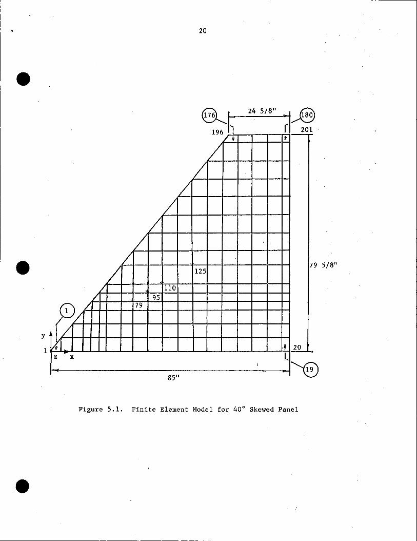
The finite element model shown in Figure 5.1 contains 201 nodes and 180
elements. The model was developed to analytically establish the concrete strains
induced in the trapezoidal shaped panel as a result of detensioning the
prestressing strands. Plate elements were used to represent the concrete within
the panel. The prestressing strands, welded wire fabric, and the two additional
No. 5 reinforcing bars along the panel diagonal edge were not included in the
analytical model. Loads representing the maximum strand forces, after elastic
shortening but before concrete creep and shrinkage and strand relaxation
occurred, were applied at the last nodes at the ends of the panel along the line
where the strands exist in the panel. These forces were obtained from the
concrete strains measured by the PML-30 polyester mold strain gauges which were ·
embedded within the panels. A comparison of the analytical and experimental
concrete strains are discussed in Sec. 6.1.
5.2. Bridge Deck Model
Finite element models of the full-scale composite bridge deck are being
developed for the five test specimens. These analytical models are being
assembled from a single layer of plate elements; therefore, the composite slab
is being approximate as a homogeneous material having isotropic properties.
Fig. 5.2 shows the finite element model containing 242 nodes and 200 elements
for the test specimen representing an interior configuration for a bridge deck.
The mesh· size selected was established from a mesh size sensitivity study,
involving comparisons of solutions by classical plate bending theory and finite
element methods, of plate bending problems having known closed-form solutions.
To maintain the desired degree of accuracy, the mesh size is smaller in the
vicinity of the concentrated wheel load location. A comparison of the analytical
-------------------------.....,
20
• ~,
196 11 24 5/8" ~1,..8
201 / . t
/ /
/ /
I I
• / 7
I 125 9 5/811
/ 110 / 95
y
0/ 79 v/' '
tL • 20
I' - l x
·, 19
1
85"
Figure 5.1. Finite Element Model for 40° Skewed Panel
•

•
82~"
• z y 232 ~
~
··0 0 .-x
0 9 i1lr·~·~~~~~~~~~~~~~~~~~~~~~~~~~~~--~l242
192"
Figure 5.2. Finite Element Model for Bridge Deck at Interior Panel Configuration (Load at x = 41.25 in. and y = 48.00 in.)
•
N ......

•
•
•
22
and experimental results for one of the wheel load positions·(x
y =.48.00.in.) on bridge deck are discussed in Sec. 6.2 .
41.25 in. and

•
•
•
23
6. Experimental and Analytical Results
6.1. Strand Development Length
The strand development length is the total concrete embedment length
* required for the ultimate stress, fsu• in the strand to be obtained at the
ultimate flexural strength of the percast member. This length consists of a
strand transfer length and a strand flexural bond length. The strand transfer
length, Lt, is the strand embedment length required to develop the effective
strand prestress, f 50 , which for pretensioned bo.nded tendons is the stress
remaining in a strand after it has been released from the prestressing .bed
anchorages and includes all losses associated with elastic shortening, concrete
shrinkage and creep, and strand relaxation. The effective pres tress, f50
, for~.
low relaxation prestressing strands is given by
0.75 f's - .6.f5 (6.1)
where, f's = ultimate strength at prestressing strand and .6.f5 = total stress loss
from all causes, excluding friction. The strand flexural bond length,· 4, is an.
additional embedment length, beyond Lt, required to increase the strand stress
* from f 50 to fsu• occurring during flexural loading of the prestressed member.
The total of the transfer and flexural bond lengths, referred to as the strand
development length, La, is expressed as
(6.2)
Many researchers have proposed expressions to evaluate the development
length, La. The AASHTO Specification Eq. (9-32) and the ACI Code.equation in
Sec. 12. 9. 1 are the same equations which are based on Hanson and Kaars' research.
Both specification expressions for the development length can be written as
(6.3)

24
* where, D = nominal strand diameter in inches. The stresses fsu and f 59 have units • of ksi. A denominator not shown in Eq. 6. 3 is equal to unity with units of ksi
and provides for consistent units. The AASHTO Specification does not separate
Eq. 6.3 into the two parts representing the transfer and flexural bond lengths,
while the AC! Code Commentary Sec. 12.9 does make the distinction. The AC! Code
Commentary equation can be rewritten as
* fse D + (fsu - fse)D (6.4) 3
The first term in Eq. (6.4) represents the strand transfer length and .the second
term represents the strand flexural bond length.
Considering the strand transfer length immediately after cutting the
prestressing strands, the only losses which have occurred are elastic shortening
• of the concrete and tendon relaxation during placing and curing of the concrete.
For this condition, the transfer length can be' expressed as
(6; 5)
where the initial prestress, fsi• for low relaxation strands is given as
0.75 f's - f 85 (6.6).
with fes = stress loss due to elastic shortening and initial strand relaxation.
The AASHTO Specification provides an expression to compute prestress loss due
to these effects. Rewriting the AASHTO Eq. 9-6,
(6.7)
• where, E5 = modulus of elasticity of the prestressing strand and Eci =modulus
of elasticity of the concrete at strand detensioning. The concrete stress, fcir,

•
•
•
25
at the center of gravity of the prestressing strands induced by the prestressing
forces immediately after strand release is given by
f - 0. 69 f' cir i- .
5
Ac A* s (6. 8)
* where A5 and Ac are a prestressing strand and tributary concrete cross-sectional
areas, respectively. Applying Eqs. 6.6 - 6.8 to the precast panels used in this
research project, f 51 = 195.0 ksi.
Another expression for the initial pres tress,· which only considers elastic
shortening, can be obtained by equating the changes in length for the concrete . .
and steel along a unit length of panel beyond the transfer length region, and
knowing that the internal concrete compressive force equals the internal strand
force. Applying these two conditions, the initial prestress can be expressed
as
0.75f' 5
(6. 9)'
[ 1 + ( ~:i) ( -:; ) Applying Eq. 6. 9 ·to the precast panels used in this research project, f 51 equals
194.5 ksi, which agrees closely with the results obtained from Eq. 6.6. This
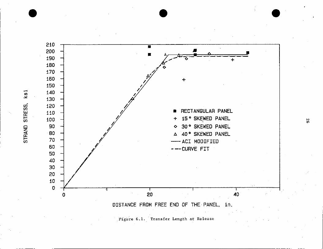
· stress is represented by the horizontal portion of the AC! Modified curve showh \
in Fig. 6 .1. The corresponding strand transfer length is obtained by
substituting this stress into Eq. 6.5, which gives Lt equal to 24.3 in. The
total panel length at the strand location would have to be twice this long in
order for the strand stress to equal the maximum initial prestress of 194.5 ksi~
If a shorter panel length exists, a decrease .in strand stress occurs as shown
by the straight line drawn between the origin and the Point A in Fig. 6.1;
• 210 200 190 180 170 160 150
...-I 140 1:1) ~ 130 en 120 en UJ 110 a: I- 100 en Cl 90 z <( BO a: I- 70 en
60 50 40 30 20 10 0
0
• • • •
+
+
• RECTANGULAR PANEL + 15 ° SKEWED PANEL <> 30 ° SKEWED PANEL l:l. 40 ° SKEWED PANEL
- ACI MODIFIED
- -- CURVE FIT
20 40.
DISTANCE FROM FREE END OF THE PANEL, in.
Fi~tire 6.1. Transfer Lengt~ at Release
• •
N 0\

27
The data points shown in Fig. 6.1 were established ·from experimentally
• measured concrete strains at known locations in four precast panels. l'he strain
readings, obtained from the PML-30 gauges which were embedded in the concrete,
were taken after the strands were cut at the prestress plant. Since the gauges·
were between adjacent strands, curve linear interpolations and extrapolations
were used to compute concrete strains at the prestressing strand locations. .The
strand stress was computed using Hooke's Law. The dotted line shown in Fig. 6.1
was visually curve fit through the computed data points. The correlation between
the experimental and analytical transfer length functions is excellent ..
Table 6.1 provides tabulated values for the transfer length, Lt,
immediately after strand release, for 3/8 in. diameter, 7 wire; .pres tressing
strands, that have been obtained by a number of researchers. The information
presented in the table for Kear, Lafraugh, and Mass; Hanson and Kaar; and Base • was obtained from an article by Zia and Mustafa .
•

•
28
Using a linear regression analysis of experimentally derived transfer len~ths
from various researchers, Zia and Mustafa have prqposed that the strand transfer
length should be given as
Lt = 1. 5 ( fs,i )o - 4. 6 f ct}
(6.10)

.. 29
where f' ci = the concrete strength at strand release. An approximate transfer
• length of about 30 in. established during this research is based o~ the visual
curve fit through the data points shown in Fig. 6.1.
A confirmation of the accuracy of the experimentally measured strain ·
values was obtained by applying the visual curve fit expression of the strand
stress versus embedment length relationship to establish .the prestress forces
in the 40° skewed panel. Knowing the available transfer lengths for the bonded
strands in the panel, the prestress force in each strand was computed. Applying.
these forces to the nodes representing the ends of the strands in the finite
element model (Fig. 5.1) the concrete strains at Nodes 79, 95, 110, and 125 were
computed. Table 6. 2 shows. that excellent correlation exists analytical and
experimental strains at these points .
• Table 6.2. Concrete Strains in 40° Skewed Panel
Analytical Experimental Node Strain Strain
No. (µ in./in.) (µ in./in.)
79 -229 -228 95 -260 -254
110 -270 -270 125 -281 -286
Strand development length has recently become a subject of controversy
and additional research on this topic is presently being pursued by others.
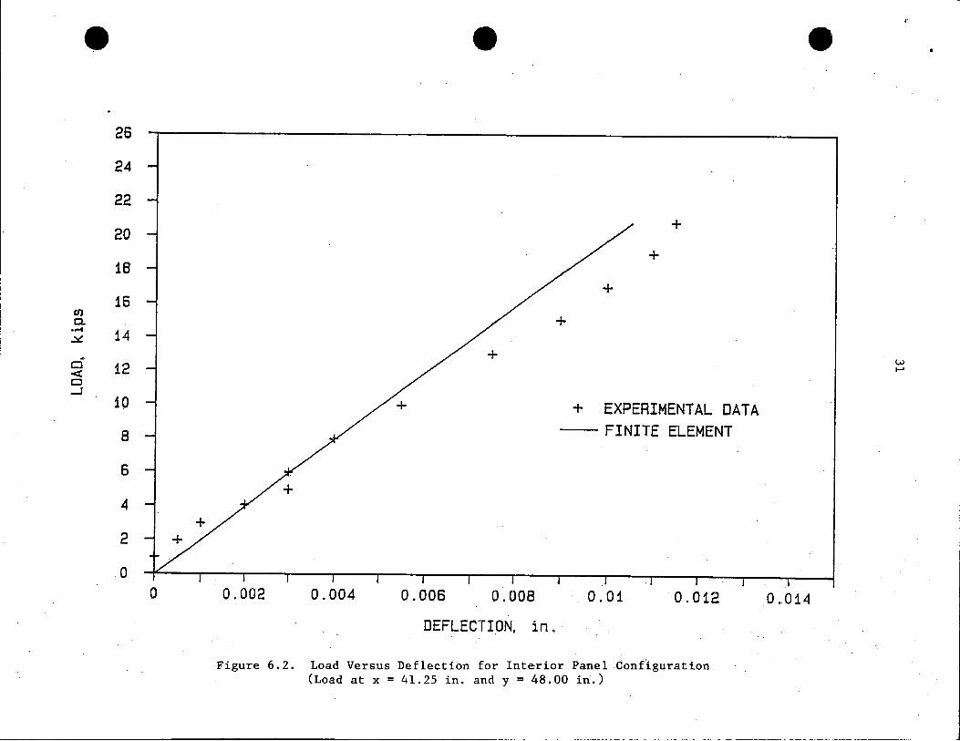
6,. 2. Bridge Deck Behavior for Interior Panel Configuration
The displacement and strain results shown for the specimen representing
• an interior panel condition are based on loads applied to an 8 in. by 20 ·in .
wheel footprint placed on the top surface of the composite slab and located at

30
the center of one of the two precast panels. · With respect to the entire specimen
• dimensions, the load point coordinate occurs at the midspan and quarter length ' . .
point (x = 41.25 in. and y = 48.00 in.). The 20 in. length for the wheel
footprint was parallel to the panel span.
Fig. 6.2 shows a load versus deflection plot for both the fini~e element
solution and the experimental test results. The vertical deflection corresponds
to the load point. The deflections shown are net displacements which account
for vertical movements at the ends of the specimen. Considering the potential
tests scatter associated with deflections of r~inforced concrete member.s and the
small magnitudes of the deflection, the correlation between the analytical
solution (solid line) and the experimentally measured displacements is very good.
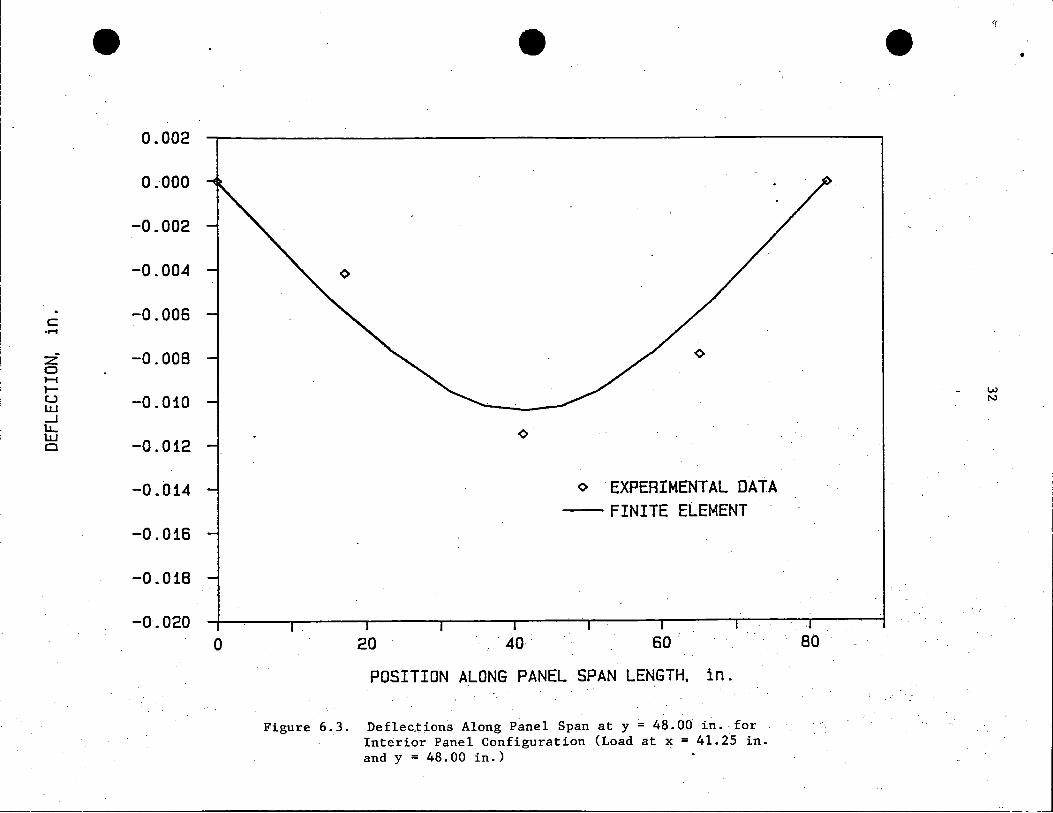
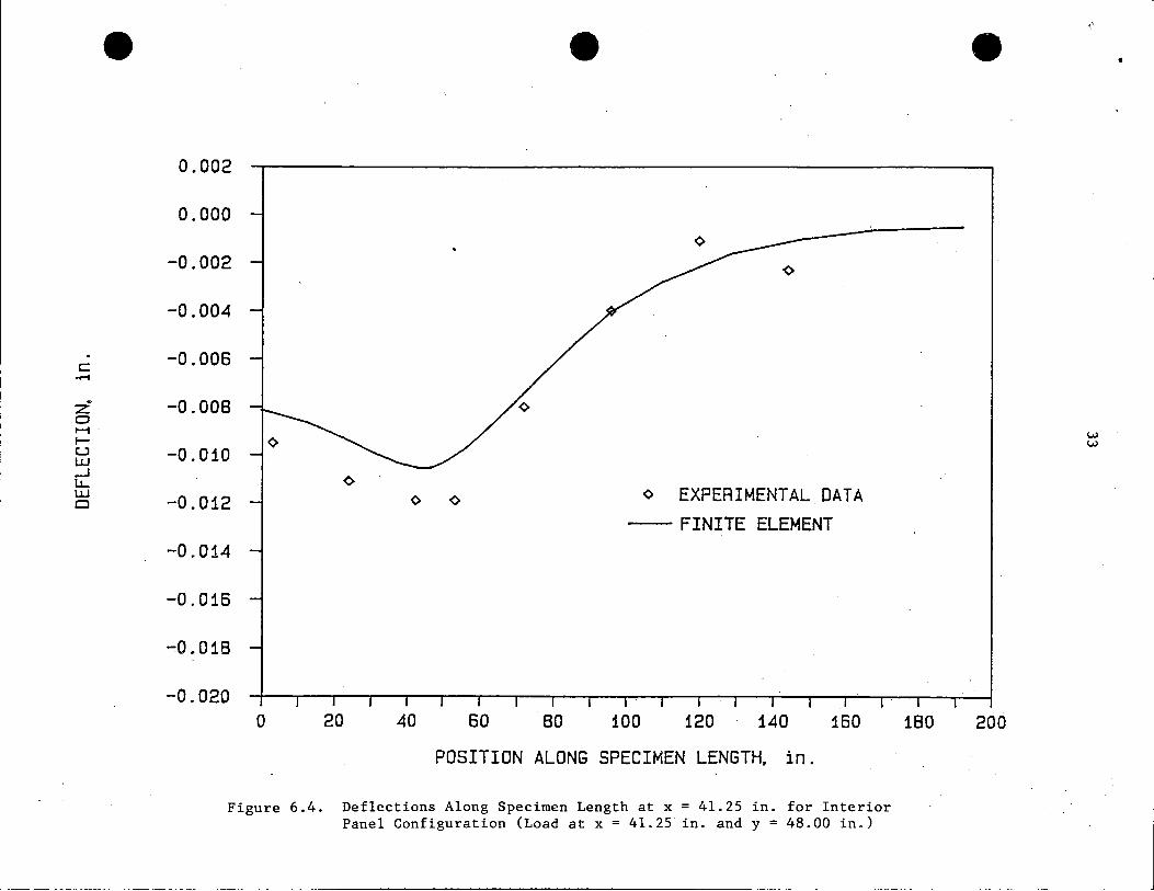
Figs. 6.3 and 6.4 show specimen displacements along the panel span and
specimen length, respectively, for an applied load equal to 20.8 kips (maximum
• AASHTO wheel load including 30% impact). The deflection variation along the
specimen length (Fig. 6.4) indicates that a point of contraflexure occurs at
the joint (y = 96.00 in.) between the two precast panels. The displacement wave
. pattern shown agrees with the anticipated results. Again, very good correlation
oi:;curs between the analytical and experimental results. The maximum experimental
deflection was less than 0.012 in.
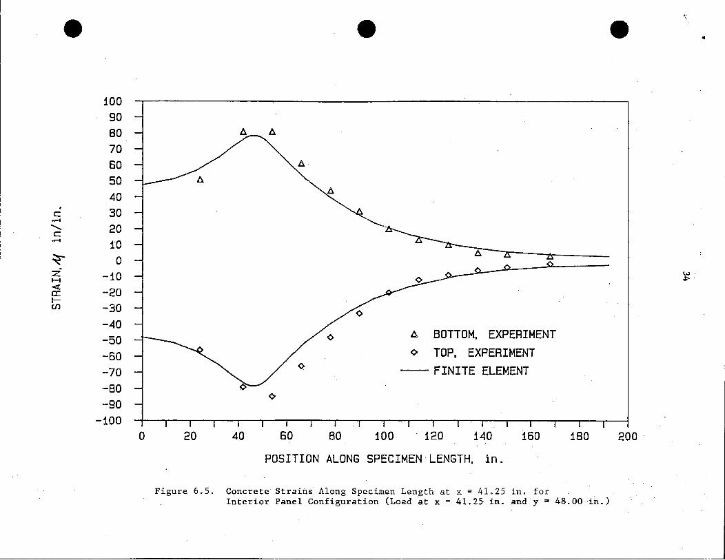
The distribution of the strains, along the midspan of the specimen, at
the top of the reinforced concrete slab and at the bottom of the precast panel,
for an applied load of 20. 8 kips, are shown in Fig. 6. 5. As expected, the
maximum strain occurs at the load point. Comparing the top and bottom fiber
strains and assuming that full composite behavior exists, the approximately equal
magnitudes of the absolute value of the experimental strains indicates that the
neutral axis occurs at the mid-thickness of the specimen. Therefore, the
• composite slab can be analytically modeled as a homogeneous material. The close
• 26
24
22
20
18
16 en c.
•...C 14 ~
Cl 12 < CJ _J
10
8
6
4
2
0 0 0.002
Figure 6.2.
•
0.004 0.006 0.008
DEFLECT I.ON, in .
+
+
+
EXPERIMENTAL DATA -- FINITE ELEMENT
0.01 0.012
Load Versus Deflection for Interior Panel Configuration (Load at x = 41.25 in. and y = 48.00 i~.)
•
0.014
• --------------------
•
20 - 40
o EXPERIMENTAL DATA -- FINITE ELEMENT
60
POSITION ALONG PANEL-SPAN LENGTH. in.
Figure 6.3. Deflec,tions Along Panel Span at y = 48.00 in. for Int~rior Panel Configuration (Load at x = 41.iS in. and y = 48.00 in.)
•
80
w N
•
•
c:: -z: 0 H· t-u lJ.J _J 1.1... UJ CJ
--- -------------------------------------
0.002
0.000
-0.002
-0.004
-0.006
-0.008
-0.010 <>
-0.012
-0.014
-0.016
-0.018
-0.020 0 20
•
<> <>
40 60 80
<> EXPERIMENTAL DATA -- FINITE ELEMENT
100 120 140 160
POSITION ALONG SPECIMEN LENGTH, in.
Figure 6.4. Deflections Along Specimen Length at x = 41.25 in. for Interior Panel Configuration (Load at x = 41.25 in. and y = 48.00 in.)
• •
180 200
• 100 90 80 70 60 50 40
• 30 c ·.-f
........... 20 c ·r-1 10 ~ 0 :z -10 1-1 < -20 a: t-CJ) -30
-40 -50 -60 -70 -80 -90
-100 0 20 40
•
60 80 100
A BOTTOM, EXPERIMENT o TOP, EXPERIMENT
-- FINITE ELEMENT
120 140 160
POSITION ALONG SPECIMEN LENGTH, in.
Figure 6.5. Concrete Straitis Along Specimen Length at x = 41.25 in. for
180
Interior Panel Configuration (Load at x = 41.25 in. and y = 48.00 -i~.)
•
200
,, l
w. ~·
•
•
•
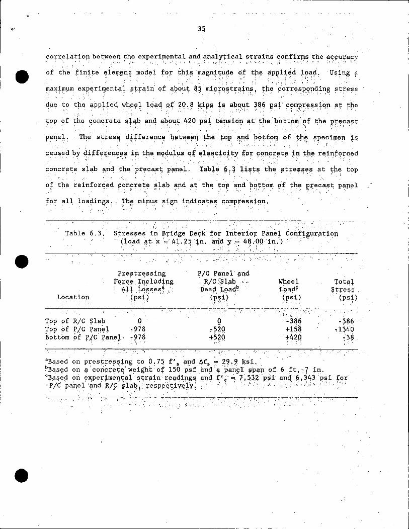
correlation between tqe experiµi~ntal and analytical strains c01:1firms the a~ptp:-acy ; • ·· .. ' ··'I '; ; ' ,.· ,', ' ,''·· , '· '., .',, ,, 1 i,',, ) , ~·~ ; .• ~;~ ~'/'!, .. ". ,.,. ,:t- • ... :,., ,'" '<: :'~· .. ,r •, :.·_· •,' e •f ;1 /., ;• ~. ,
of the' finite ~ie~~11~ ~od~l, t~~ th!~ ·inagn+f~pe ~f tp~ a.p~1+:,d i~a{ u~~n~ fl
111ax~~µ~ exP;~ri~entaT ·~;r~in'. 9~ ~~qh~· ~~.· qi~fq~tr~i~~; ~h~: pqrf~~~·~~q~n~ ~H~¢~s ~4~ to tp~ a,~p~~~~ !"lte~~ lp~~ q~ 2,Q ~ ~ ~ipi; f.~ ap9~~ ~~~ ps;" c?n.iP;r~~~tqp F~ ~pe
.: • : 1 , • • •. :,.'· • , • :· , ; • • • • r ; · : . · i • :- ! : · • · .:· 1 :. • ~ • -~ ·:· :· ·' ~ •
t;op of the concrete ~+~b ii~4 ~bo~t; ~~Q ps~ ~!'msitj;i. a,t,' t,h~ pott~m' 9£ t;h~ EJ:.'.eC~St ;' ' ' , ' I"\ , ·• • . ,.~· ' ' ' ', ,. '• : ; ,.' •' ' '• I • ,• '''I ' • ' I •' '" ', • '·, '.· '" :, / l .• ·," •' '
'.fqe s~res~ tlHfe~~nc~ Qet"Y?~~'9 tq7 t0,P,· ~nq p<:>~t~ll\ ~f ~fl~ ~?ecil!len ~:;; ' ' •., ' • • ;: • • • • ' • : • ' • • • • ' ; • • : ~ • '. : t • ; • ' •• ! . . ' ''. : ' . ' ' j • '
cau~ed ?Y ~itf~r~n9~~ i~ t.h~ m~~ul~~ o.f ~l~~t~~}t~ ;or ~qnp~~t~ ~? t;r~ 're,i~f9rq~d , . ' • ~ ·: • ' ' . • f • :· ' . • • • . ' '. . ', .. '~ ·~ ' ' • , .· ; ' . • :•., ' . t • ' • • •• ; • • • • ' ' :
c~mcr~t;e sl~b ~nd !=h~ pr~c~~~ p~n~:l-. Tab}~ ~; ~ H~t!'! th~ ~fre$~r~ at 7~~ t~p ' . . ~ ' . ·. , ; . . . '
- ~ ! •
I ' •· ..
s~res$e~ in ~ridge !;)eek ~or Interio~ Pane} Co11figur~tiop 'q~"cid ?,t x 'o;;, 41.75 ~n. arid 'y .~ 48.00· in.)'•' , . '
•• " . , . ;~ , ; ; r . , , , : i. ~· . ~/. ·~ :.' i:. , £ • , !
Loca,tion
fre~tr~ssing f'9;:~r?, ~tjcluding · All Lcisses 8
• ' , .. (p~i)' ·' ,,: .· ' ~ :· ' 1' '
'•-'
~PP of R/C ~lab 0 ~PP pf P/G ~anei ~97~ Bpttom ~f f /C f~nei · "~78
; L
' '
:, .. t . ,-; ,. ,. I.
~-... ;. ' · .
P/O r~nel·§.nd .. R/C (~la.b ... ·· l;)eaq ~9a.d~ ·
<'r~~) , ',i,· ··:,'-'
Q -520 t5M
'I . • ,,···~" .;. :·, ··.··
. .. , .. ·
Wh~el ~oa<:l~ ·(psi)
' ~ ;, ·' '',
, .. '. r ~ ,~.- ·;,··-... -38,9 +158
t~~~
Tot~+ §trel:!~ ., (psi)
' ',.
~3~q ~1340
~3? :: ·:.
.'! •,
8 Based on prest~e~~tn& tq 0~7? f's an4 *fs ~ 22.9 ~~i 1
for bB~sed on ~·coric:r~~~'weig;ht·of 150 p'~f an~·~ 'i>an~1 ~PaP qf 6 ft,~7 j.11. c!3~s~<:l <m ~~per~mep~al. ·st;r~;n:readiP,g~ '<j-ncl ~';;' =; -?~?~~"p#· ari.4 ~·~~~ p~i · P/C pa,ne+ 'find~/~ ~lia1?, resp~gtiy_~ly. · · · : "" · .,,. · ·' '·'' · :;
. ' . ' . . ~ , . ' . ·,. . .
... 'I,•.·.,,'•';
':·· ~·: I' " ·r,. ,. ,

36
7. Future Work 7.1. Experimental
• After the completion of the testing for the first configuration of the
full scale composite slab, representing an interior panel condition, four more
specimens will be prepared and tested. These specimens will have configurations
representing panel conditions adjacent to abutment or pier diaphragms having skew
angles of 0, 15, 30, and 40 degrees. The specimens will be constructed and
tested as discussed in Sec. 4.
7.2. Analytical
Finite element models will be established to analyze the four remaining
specimens in the experimental program. In addition, simplified analyses will
be applied using basic engfneering mechanics principles associated with a
strength of materials approach. Comparisons of the displacements and strains
• between the experimental and analytical results will be made to establish the
accuracy of the analytical models. I
For the precast prestressed concrete panels in the slab configuration
representing an interior panel condition, conventional prestressed concrete
design principles will be applied to establish the concrete and steel tendon
strains and stresses .
•

... -.•· ~·· ·, ' ...
37
8. Acknowledgements
• The study presented in this interim report . is being conducted by the
Engineering Research Institute of Iowa State University and is being sponsored
by the Iowa Department of Transportation, Highway Division, through the Iowa
Highway Research Board.
The author extends his sincere appreciation to William Lundquist and John
' . i Harkin from the Iowa Department of Transportation and Henry Gee formerly with
the Iowa DOT for their· support and assistance with the research work on precast
pres tressed concrete panel subdecks. Donald Henrich, general manager of Precas t
Concrete Operations, a Division of Wheeler Consolidated, Inc., i,n Iowa Falls,
IA, has provided the precast panels for the experimental testing program and has
provided photographs of bridge deck construction of one of the bridges inspected
in this study. For Don's assistance the author expresses his gratitude .
• The author wishes to thank Harryanto Pratanata, a graduate student in
Structural Engineering, for his help in conducting the research. Thanks go to
Douglas Wood, Structural Laboratory Supervisor, for his valuable assistance with
the ex-perimental program. Graduate students Arif Mahmood, who wrote the computer
programs to compile the survey results, and Roger Khoury who assisted in.
tabulating the questionnaire results are thanked for their efforts. Scott
Keating, a graduate student, and Eric Schallert, an undergraduate student,
performed the majority of the fabrication on the test and instrumentation
frameworks. For their help on this aspect of the project, the author expresses
his appreciation. Undergraduate students David Bartels, Paul Boring, Brian
Corzine, Ronald Dehart, Bret Farmer, Craig Hawkinson, Jeffrey Heilstedt, and
Jonathan Lutz also contributed significantly to the laboratory effort of this
research project. The author wishes to thank Denise Wood, structures secretary,
• for typing this report.
i
I
I -