Flexural Behaviour of Precast, Prestressed Ribbed RPC ... · Flexural Behaviour of Precast, ......
9
Send Orders for Reprints to [email protected] The Open Civil Engineering Journal, 2015, 9, 535-543 535 1874-1495/15 2015 Bentham Open Open Access Flexural Behaviour of Precast, Prestressed Ribbed RPC Bottom Panels Zheng Wenzhong*, Lu Xueyuan and Wang Ying Key Lab of Structures Dynamic Behavior and Control of the Ministry Education, Harbin Institute of Technology, Harbin 150090, P.R. China Abstract: This study introduces a new type of precast, prestressed reactive powder concrete (RPC) bottom panel for a large-span composite slab. The bottom panels, which have one or two inverted ribs with openings, act as formwork during the construction stage. The paper experimentally investigated the crack characteristics, deflection, and normal section bearing capacity of four precast, prestressed ribbed RPC bottom panels under flexural load. The results indicated that the RPC ultimate strain under non-uniform compression is 550010 -6 and the plastic influence coefficient of the section modulus is linear with the longitudinal reinforcement ratio. The tensile stress of RPC at the cracked section should be considered while calculating the flexural stiffness; the equation used to determine the nominal tensile stress of RPC as a major variable for calculating the crack width at the bottom of panels was proposed. The bottom panels generally exhibit an over-reinforced failure mode behaviour without the composite layer; the calculation method of the normal section bear- ing capacity of this mode was established. Keywords: Crack width, flexural stiffness, normal section bearing capacity, precast, prestressed ribbed RPC bottom panel, reactive powder concrete. 1. INTRODUCTION The composite slab is a semi-fabricated system that con- sists of a precast bottom panel and a composite layer. The precast bottom panel acts as formwork during the construc- tion stage and then forms an integral part of the composite layer after the solidification of cast-in-place concrete. Com- pared with cast-in-place slabs, composite slabs have the ad- vantages of low cost, rapid construction and improved qual- ity control, which have led to its widespread application throughout the world [1]. To improve the integrity of the two layers, a precast bottom panel with rough surfaces [2, 3] or with lattice steel truss projects at the top [4-6] can be used. Precast bottom panels with a rough surface are easy to pro- duce but have small spans. Precast bottom panels with lattice steel truss projects at the top have better integrity and larger spans; however, steel trusses are expensive if they are ap- plied in large spans. To overcome these problems, Jiang Qingqing [7] proposed a precast bottom slab with an in- verted rib that has better flexural stiffness and bearing capac- ity, which can be applied in larger spans and can reduce cost. To produce two-way composite slabs and further improve the integrity of the two layers, Wu Fangbo [8, 9] and Zhou Youxiang [10] proposed the use of solid and hollow compos- ite slabs with precast, prestressed ribbed bottom panels, re- spectively. The precast bottom panels and their composite slabs are shown in Fig. (1). A row of inverted ribs, on which rectangular openings are set, is located in the middle of the precast bottom panel of a solid composite slab (Fig. (1). (a1)). Following the assembly of the bottom panel, transverse rein- forcements can be arranged in the rectangular openings, and a two-way solid composite slab that has good integrity is formed after the cast-in-place concrete is poured and hard- ened (Fig. (1). (a2)). A double-rib precast bottom panel is applied in hollow composite slabs (Fig. (1). (b1)). Each side of the bottom panel contains a row of inverted ribs with rec- tangular openings. Lightweight materials can be placed be- tween the two rows of ribs during construction. Following assembly, transverse reinforcements can be arranged in the openings and a two-way hollow composite slab that has good integrity is formed after solidification of the cast-in- place concrete (Fig. (1). (b2)). The applicable spans of both composite slabs mentioned above are generally less than 8 m. One reason for the limited span is that the prestressing wires in precast bottom panels provide most of the rein- forcement of a composite slab; as a result, as the span of a composite slab increases, the amount of prestressing in the bottom panel must be increased, which leads to the excessive elastic compression and creeping loss of the prestress. An- other reason is that the flexural crack strain of an ordinary concrete is relatively low, so the crack width and deflection most likely cannot satisfy the serviceability requirements. To avoid these problems, we proposed using reactive powder concrete (RPC) instead of ordinary concrete to manufacture the precast, prestressed ribbed bottom panels mentioned above. RPC is a relatively new cement matrix composite that was invented in the 1990’s [11, 12]; RPC has ultra-high me- chanical properties (the compressive strength is generally in the range of 100-230 MPa) and superior durability [13, 14], and it can be used as an excellent building material. Cur- rently, RPC is used in many types of construction, including
Transcript of Flexural Behaviour of Precast, Prestressed Ribbed RPC ... · Flexural Behaviour of Precast, ......
Send Orders for Reprints to [email protected]
The Open Civil Engineering Journal, 2015, 9, 535-543 535
1874-1495/15 2015 Bentham Open
Open Access
Flexural Behaviour of Precast, Prestressed Ribbed RPC Bottom Panels
Zheng Wenzhong*, Lu Xueyuan and Wang Ying
Key Lab of Structures Dynamic Behavior and Control of the Ministry Education, Harbin Institute of Technology, Harbin
150090, P.R. China
Abstract: This study introduces a new type of precast, prestressed reactive powder concrete (RPC) bottom panel for a
large-span composite slab. The bottom panels, which have one or two inverted ribs with openings, act as formwork during
the construction stage. The paper experimentally investigated the crack characteristics, deflection, and normal section
bearing capacity of four precast, prestressed ribbed RPC bottom panels under flexural load. The results indicated that the
RPC ultimate strain under non-uniform compression is 5500 10-6
and the plastic influence coefficient of the section
modulus is linear with the longitudinal reinforcement ratio. The tensile stress of RPC at the cracked section should be
considered while calculating the flexural stiffness; the equation used to determine the nominal tensile stress of RPC as a
major variable for calculating the crack width at the bottom of panels was proposed. The bottom panels generally exhibit
an over-reinforced failure mode behaviour without the composite layer; the calculation method of the normal section bear-
ing capacity of this mode was established.
Keywords: Crack width, flexural stiffness, normal section bearing capacity, precast, prestressed ribbed RPC bottom panel, reactive powder concrete.
1. INTRODUCTION
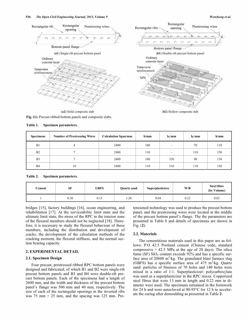
The composite slab is a semi-fabricated system that con-sists of a precast bottom panel and a composite layer. The precast bottom panel acts as formwork during the construc-tion stage and then forms an integral part of the composite layer after the solidification of cast-in-place concrete. Com-pared with cast-in-place slabs, composite slabs have the ad-vantages of low cost, rapid construction and improved qual-ity control, which have led to its widespread application throughout the world [1]. To improve the integrity of the two layers, a precast bottom panel with rough surfaces [2, 3] or with lattice steel truss projects at the top [4-6] can be used. Precast bottom panels with a rough surface are easy to pro-duce but have small spans. Precast bottom panels with lattice steel truss projects at the top have better integrity and larger spans; however, steel trusses are expensive if they are ap-plied in large spans. To overcome these problems, Jiang Qingqing [7] proposed a precast bottom slab with an in-verted rib that has better flexural stiffness and bearing capac-ity, which can be applied in larger spans and can reduce cost. To produce two-way composite slabs and further improve the integrity of the two layers, Wu Fangbo [8, 9] and Zhou Youxiang [10] proposed the use of solid and hollow compos-ite slabs with precast, prestressed ribbed bottom panels, re-spectively. The precast bottom panels and their composite slabs are shown in Fig. (1). A row of inverted ribs, on which rectangular openings are set, is located in the middle of the precast bottom panel of a solid composite slab (Fig. (1). (a1)).
Following the assembly of the bottom panel, transverse rein-forcements can be arranged in the rectangular openings, and a two-way solid composite slab that has good integrity is formed after the cast-in-place concrete is poured and hard-ened (Fig. (1). (a2)). A double-rib precast bottom panel is applied in hollow composite slabs (Fig. (1). (b1)). Each side of the bottom panel contains a row of inverted ribs with rec-tangular openings. Lightweight materials can be placed be-tween the two rows of ribs during construction. Following assembly, transverse reinforcements can be arranged in the openings and a two-way hollow composite slab that has good integrity is formed after solidification of the cast-in-place concrete (Fig. (1). (b2)). The applicable spans of both composite slabs mentioned above are generally less than 8 m. One reason for the limited span is that the prestressing wires in precast bottom panels provide most of the rein-forcement of a composite slab; as a result, as the span of a composite slab increases, the amount of prestressing in the bottom panel must be increased, which leads to the excessive elastic compression and creeping loss of the prestress. An-other reason is that the flexural crack strain of an ordinary concrete is relatively low, so the crack width and deflection most likely cannot satisfy the serviceability requirements. To avoid these problems, we proposed using reactive powder concrete (RPC) instead of ordinary concrete to manufacture the precast, prestressed ribbed bottom panels mentioned above.
RPC is a relatively new cement matrix composite that was invented in the 1990’s [11, 12]; RPC has ultra-high me-chanical properties (the compressive strength is generally in the range of 100-230 MPa) and superior durability [13, 14], and it can be used as an excellent building material. Cur-rently, RPC is used in many types of construction, including
536 The Open Civil Engineering Journal, 2015, Volume 9 Wenzhong et al.
bridges [15], factory buildings [16], ocean engineering, and rehabilitation [17]. At the serviceability limit state and the ultimate limit state, the stress of the RPC in the tension zone of the flexural members should not be neglected [18]. There-fore, it is necessary to study the flexural behaviour of these members, including the distribution and development of cracks, the development of the calculation methods of the cracking moment, the flexural stiffness, and the normal sec-tion bearing capacity.
2. EXPERIMENTAL DETAIL
2.1. Specimen Design
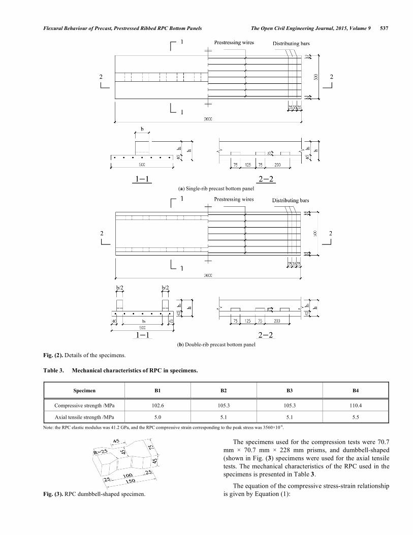
Four precast, prestressed ribbed RPC bottom panels were designed and fabricated, of which B1 and B2 were single-rib precast bottom panels and B3 and B4 were double-rib pre-cast bottom panels. Each of the specimens had a length of 2600 mm, and the width and thickness of the precast bottom panel’s flange was 500 mm and 40 mm, respectively. The size of each of the rectangular openings in the inverted ribs was 75 mm 25 mm, and the spacing was 125 mm. Pre-
tensioned technology was used to produce the precast bottom panel, and the prestressing wires were located at the middle of the precast bottom panel’s flange. The the parameters are presented in Table 1 and details of specimens are shown in Fig. (2).
2.2. Materials
The cementitious materials used in this paper are as fol-lows: P·O 42.5 Portland cement (Chinese code, standard compressive > 42.5 MPa at the age of 28 days). The silica fume (SF) SiO2 content exceeds 92% and has a specific sur-face area of 20600 m
2/kg. The granulated blast furnace slag
(GBFS) has a specific surface area of 475 m2/kg. Quartz
sand: particles of fineness of 70 holes and 140 holes were mixed in a ratio of 1:1. Superplasticizer: polycarboxylate was used as a superplasticizer in the RPC mixes. Copperized steel fibres that were 13 mm in length and 0.22 mm in di-ameter were used. The specimens remained in the formwork for 24 h and were autoclaved at 90-95°C for 12 h to acceler-ate the curing after demoulding as presented in Table 2.
(a1) Single-rib precast bottom panel (b1) Double-rib precast bottom panel
(a2) Solid composite slab (b2) Hollow composite slab
Fig. (1). Precast ribbed bottom panels and composite slabs.
Table 1. Specimen parameters.
Specimens Number of Prestressing Wires Calculation Span/mm b/mm b1/mm h1/mm h/mm
B1 4 2400 100 - 70 110
B2 7 2400 110 - 110 150
B3 7 2400 100 320 90 130
B4 10 2400 110 310 110 150
Table 2. Specimen parameters.
Cement SF GBFS Quartz sand Superplasticizer W/B Steel fibre
(by Volume)
1 0.30 0.15 1.20 0.04 0.22 0.02
Flexural Behaviour of Precast, Prestressed Ribbed RPC Bottom Panels The Open Civil Engineering Journal, 2015, Volume 9 537
(a) Single-rib precast bottom panel
(b) Double-rib precast bottom panel
Fig. (2). Details of the specimens.
Table 3. Mechanical characteristics of RPC in specimens.
Specimen B1 B2 B3 B4
Compressive strength /MPa 102.6 105.3 105.3 110.4
Axial tensile strength /MPa 5.0 5.1 5.1 5.5
Note: the RPC elastic modulus was 41.2 GPa, and the RPC compressive strain corresponding to the peak stress was 3560 10-6.
Fig. (3). RPC dumbbell-shaped specimen.
The specimens used for the compression tests were 70.7
mm 70.7 mm 228 mm prisms, and dumbbell-shaped
(shown in Fig. (3) specimens were used for the axial tensile
tests. The mechanical characteristics of the RPC used in the
specimens is presented in Table 3.
The equation of the compressive stress-strain relationship
is given by Equation (1):

538 The Open Civil Engineering Journal, 2015, Volume 9 Wenzhong et al.
fc=
1.55
0
1.2
0
4
+ 0.65
0
5
0
6
0
1
2
+
0
(1)
where is the compressive stress of the RPC prism; cf is
the compressive strength of the RPC prism; is the
compressive strain of the RPC prism; and0
is the
compressive strain corresponding to the peak stress of RPC.
The reinforcement in the specimens consisted of low re-laxation spiral ribbed wires with an elastic modulus of 193 GPa, a strength of 1,588 MPa and a yield strength of 1,451 MPa. The controlled stress for the stretching was 1,020 MPa.
2.3. Experimental Device
Specimens were simply supported and tested under two-concentrated line loads applied at the middle-third of the slabs. To conveniently observe the cracks, the bottom faces of the specimens were oriented upward. To avoid the shear lag effect [19], rigidity blocks were used to level the ribs and flange of each of the specimens. The mid-span deflection was monitored using linear variable differential transformers (LVDTs). Resistance strain gauges were continuously at-tached at the top of ribs and the bottom surface of specimens of the pure bending section; the experimental device is shown in Fig. (4). At each level of load, the width of each crack at the intersection points with prestressing wires were monitored using a crack-width measurement instrument (0.002 mm), and the new cracks were marked.
2.4. Measurement of the Effective Prestress
To accurately determine the effective prestress of the prestressing wires in the specimens, the bottoms of the ribbed RPC bottom panels (which were fabricated under the same conditions) were grooved to expose the prestressing wires and resistance strain gauges were attached, as shown in Fig. (5). The changes in strain were measured by a strain collection system, and then, the effective prestress in the prestressing wires was calculated.
3. STRUCTURAL RESPONSE
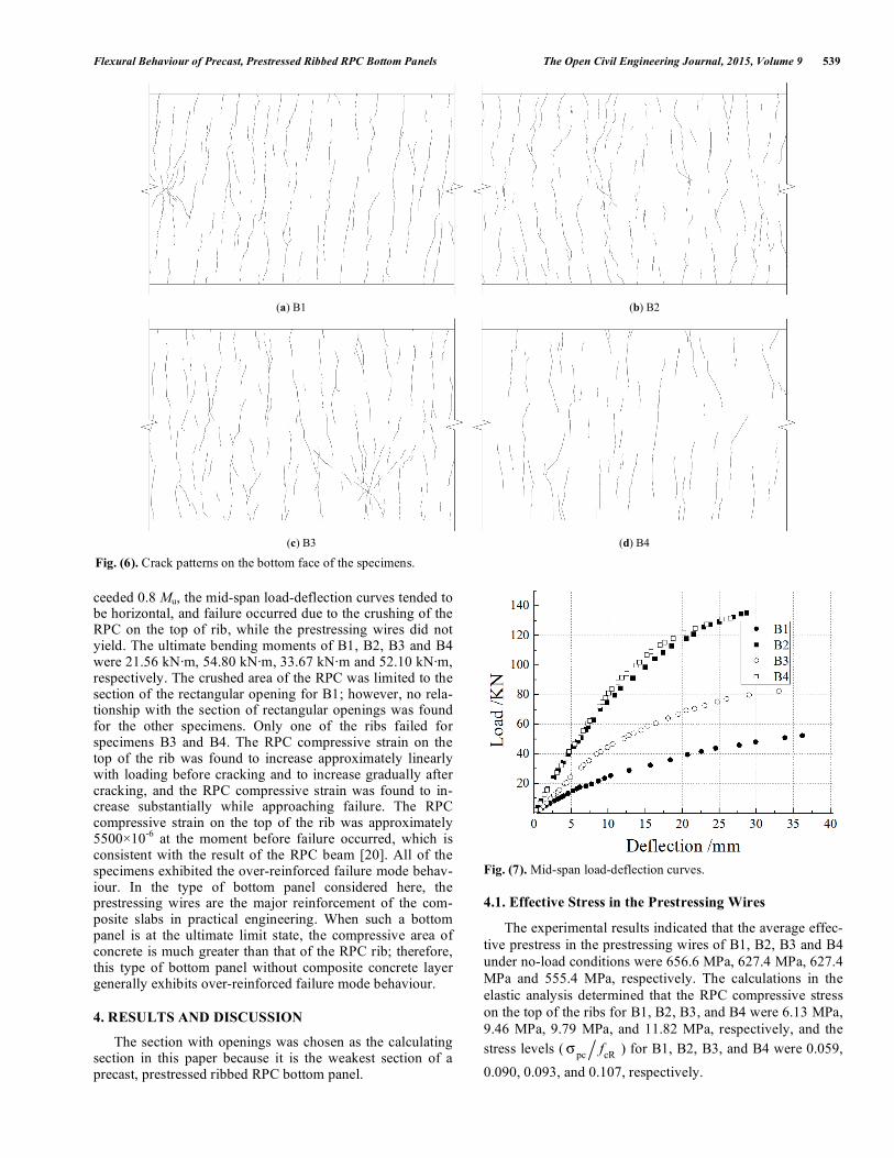
The cracking moments of B1, B2, B3 and B4 were 7.67 kN·m, 20.26 kN·m, 14.90 kN·m and 25.11 kN·m, respec-tively. The first crack of each of the specimens appeared at the section with the opening. The cracks extended and wid-ened with loading, and some of the cracks extended to the upper face of the flange of each specimen; however, no crack was found on the ribs. Cracks disappeared after extending across some distance and then randomly appeared again at a nearby location and continued to extend in the same direc-tion. The cracks on the bottom face of the flange of each specimen were fine, dense and discontinuous, and no consis-tent crack spacing was observed. The crack width was obvi-ously narrower than that of an ordinary concrete flexural member: at the mid-span moment of 0.95 times the ultimate bending moment (Mu), the observed maximum crack width was 0.2 mm. New cracks were constantly emerging until the ultimate bending moment; the crack patterns of the pure bending section on the bottom face of specimens are shown in Fig. (6).
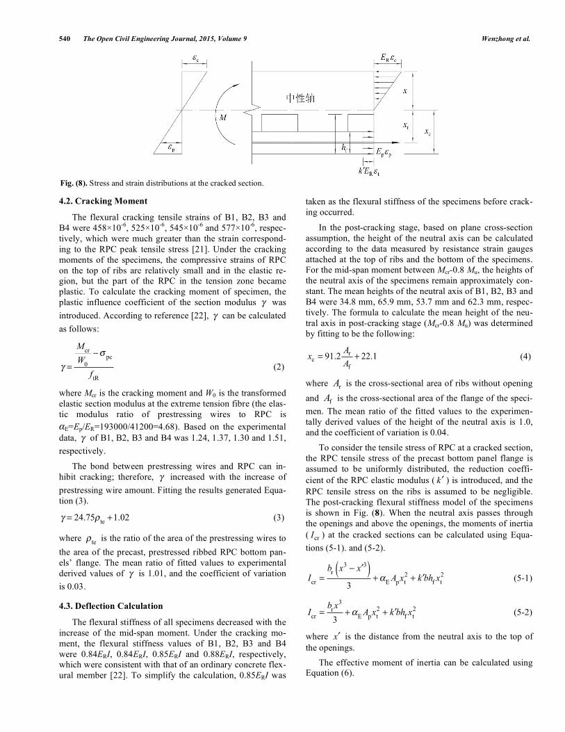
The mid-span load-deflection curves of all of the speci-mens are shown in Fig. (7). The mid-span deflections were approximately linear with the load before cracking and be-came larger gradually after cracking. When the load ex-
LVDT
BlockLVDTLVDT
P/2 P/2
800 800800
2400
Fig. (4). Experimental device.
Fig. (5). Measurement of the effective prestress.
Flexural Behaviour of Precast, Prestressed Ribbed RPC Bottom Panels The Open Civil Engineering Journal, 2015, Volume 9 539
ceeded 0.8 Mu, the mid-span load-deflection curves tended to be horizontal, and failure occurred due to the crushing of the RPC on the top of rib, while the prestressing wires did not yield. The ultimate bending moments of B1, B2, B3 and B4 were 21.56 kN·m, 54.80 kN·m, 33.67 kN·m and 52.10 kN·m, respectively. The crushed area of the RPC was limited to the section of the rectangular opening for B1; however, no rela-tionship with the section of rectangular openings was found for the other specimens. Only one of the ribs failed for specimens B3 and B4. The RPC compressive strain on the top of the rib was found to increase approximately linearly with loading before cracking and to increase gradually after cracking, and the RPC compressive strain was found to in-crease substantially while approaching failure. The RPC compressive strain on the top of the rib was approximately 5500 10
-6 at the moment before failure occurred, which is
consistent with the result of the RPC beam [20]. All of the specimens exhibited the over-reinforced failure mode behav-iour. In the type of bottom panel considered here, the prestressing wires are the major reinforcement of the com-posite slabs in practical engineering. When such a bottom panel is at the ultimate limit state, the compressive area of concrete is much greater than that of the RPC rib; therefore, this type of bottom panel without composite concrete layer generally exhibits over-reinforced failure mode behaviour.
4. RESULTS AND DISCUSSION
The section with openings was chosen as the calculating section in this paper because it is the weakest section of a precast, prestressed ribbed RPC bottom panel.
Fig. (7). Mid-span load-deflection curves.
4.1. Effective Stress in the Prestressing Wires
The experimental results indicated that the average effec-
tive prestress in the prestressing wires of B1, B2, B3 and B4
under no-load conditions were 656.6 MPa, 627.4 MPa, 627.4
MPa and 555.4 MPa, respectively. The calculations in the
elastic analysis determined that the RPC compressive stress
on the top of the ribs for B1, B2, B3, and B4 were 6.13 MPa,
9.46 MPa, 9.79 MPa, and 11.82 MPa, respectively, and the
stress levels ( pc
fcR
) for B1, B2, B3, and B4 were 0.059,
0.090, 0.093, and 0.107, respectively.
(a) B1 (b) B2
(c) B3 (d) B4
Fig. (6). Crack patterns on the bottom face of the specimens.
540 The Open Civil Engineering Journal, 2015, Volume 9 Wenzhong et al.
4.2. Cracking Moment
The flexural cracking tensile strains of B1, B2, B3 and
B4 were 458 10-6
, 525 10-6
, 545 10-6
and 577 10-6
, respec-
tively, which were much greater than the strain correspond-
ing to the RPC peak tensile stress [21]. Under the cracking
moments of the specimens, the compressive strains of RPC
on the top of ribs are relatively small and in the elastic re-
gion, but the part of the RPC in the tension zone became
plastic. To calculate the cracking moment of specimen, the
plastic influence coefficient of the section modulus was
introduced. According to reference [22], can be calculated
as follows:
=
Mcr
W0
pc
ftR
(2)
where Mcr is the cracking moment and W0 is the transformed
elastic section modulus at the extreme tension fibre (the elas-
tic modulus ratio of prestressing wires to RPC is
E=Ep/ER=193000/41200=4.68). Based on the experimental
data, of B1, B2, B3 and B4 was 1.24, 1.37, 1.30 and 1.51,
respectively.
The bond between prestressing wires and RPC can in-
hibit cracking; therefore, increased with the increase of
prestressing wire amount. Fitting the results generated Equa-
tion (3).
= 24.75
te+1.02 (3)
where te
is the ratio of the area of the prestressing wires to
the area of the precast, prestressed ribbed RPC bottom pan-
els’ flange. The mean ratio of fitted values to experimental
derived values of is 1.01, and the coefficient of variation
is 0.03.
4.3. Deflection Calculation
The flexural stiffness of all specimens decreased with the
increase of the mid-span moment. Under the cracking mo-
ment, the flexural stiffness values of B1, B2, B3 and B4
were 0.84ERI, 0.84ERI, 0.85ERI and 0.88ERI, respectively,
which were consistent with that of an ordinary concrete flex-
ural member [22]. To simplify the calculation, 0.85ERI was
taken as the flexural stiffness of the specimens before crack-
ing occurred.
In the post-cracking stage, based on plane cross-section
assumption, the height of the neutral axis can be calculated
according to the data measured by resistance strain gauges
attached at the top of ribs and the bottom of the specimens.
For the mid-span moment between Mcr-0.8 Mu, the heights of
the neutral axis of the specimens remain approximately con-
stant. The mean heights of the neutral axis of B1, B2, B3 and
B4 were 34.8 mm, 65.9 mm, 53.7 mm and 62.3 mm, respec-
tively. The formula to calculate the mean height of the neu-
tral axis in post-cracking stage (Mcr-0.8 Mu) was determined
by fitting to be the following:
r
c
f
91.2 22.1A
xA
= + (4)
where rA is the cross-sectional area of ribs without opening
and fA is the cross-sectional area of the flange of the speci-
men. The mean ratio of the fitted values to the experimen-
tally derived values of the height of the neutral axis is 1.0,
and the coefficient of variation is 0.04.
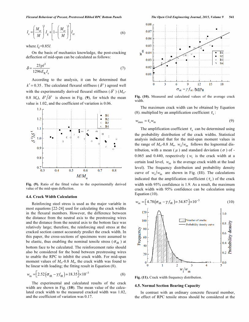
To consider the tensile stress of RPC at a cracked section,
the RPC tensile stress of the precast bottom panel flange is
assumed to be uniformly distributed, the reduction coeffi-
cient of the RPC elastic modulus ( k ) is introduced, and the
RPC tensile stress on the ribs is assumed to be negligible.
The post-cracking flexural stiffness model of the specimens
is shown in Fig. (8). When the neutral axis passes through
the openings and above the openings, the moments of inertia
(crI ) at the cracked sections can be calculated using Equa-
tions (5-1). and (5-2).
I
cr=
br
x3
x3( )
3+
EA
px
t
2+ k bh
fx
t
2 (5-1)
I
cr=
brx
3
3+
EA
px
t
2+ k bh
fx
t
2 (5-2)
where x is the distance from the neutral axis to the top of
the openings.
The effective moment of inertia can be calculated using Equation (6).
Fig. (8). Stress and strain distributions at the cracked section.
Flexural Behaviour of Precast, Prestressed Ribbed RPC Bottom Panels The Open Civil Engineering Journal, 2015, Volume 9 541
Ie=
Mcr
M
3
Ig+ 1
Mcr
M
3
Icr (6)
where Ig=0.85I.
On the basis of mechanics knowledge, the post-cracking deflection of mid-span can be calculated as follows:
=23pl3
1296ER
Ie
(7)
According to the analysis, it can be determined that
0.35k = . The calculated flexural stiffness ( c ) agreed well
with the experimentally derived flexural stiffness ( t ) (Mcr-
0.8 Mu), c t
is shown in Fig. (9), for which the mean
value is 1.02, and the coefficient of variation is 0.06.
Fig. (9). Ratio of the fitted value to the experimentally derived
value of the mid-span deflection.
4.4. Crack Width Calculation
Reinforcing steel stress is used as the major variable in
most equations [22-24] used for calculating the crack widths
in the flexural members. However, the difference between
the distance from the neutral axis to the prestressing wires
and the distance from the neutral axis to the bottom face was
relatively large; therefore, the reinforcing steel stress at the
cracked section cannot accurately predict the crack width. In
this paper, the cross-sections of specimens were assumed to
be elastic, thus enabling the nominal tensile stress (tR
) at
bottom face to be calculated. The reinforcement ratio should
also be considered for the bond between prestressing wires
to enable the RPC to inhibit the crack width. For mid-span
moment values of Mcr-0.8 Mu, the crack width was found to
be linear with loading; the fitting result in Equation (8).
w
m= 2.52
tRftR( ) +18.35 10
3 (8)
The experimental and calculated results of the crack width are shown in Fig. (10). The mean value of the calcu-lated crack width to the measured cracked width was 1.02, and the coefficient of variation was 0.17.
Fig. (10). Measured and calculated values of the average crack
width.
The maximum crack width can be obtained by Equation
(8). multiplied by an amplification coefficient s
:
max s mw w= (9)
The amplification coefficient s
can be determined using
the probability distribution of the crack widths. Statistical
analysis indicated that for the mid-span moment values in
the range of Mcr-0.8 Mu, i mw w follows the lognormal dis-
tribution, with a mean ( μ ) and standard deviation ( ) of -
0.065 and 0.440, respectively (iw is the crack width at a
certain load level, mw is the average crack width at the load
level). The frequency distribution and probability density
curve of i mw w are shown in Fig. (11). The calculations
indicated that the amplification coefficient (s
) of the crack
width with 95% confidence is 1.9. As a result, the maximum
crack width with 95% confidence can be calculation using
Equation (10).
( ) 3
m tR tR4.78 34.87 10w f= + (10)
Fig. (11). Crack width frequency distribution.
4.5. Normal Section Bearing Capacity
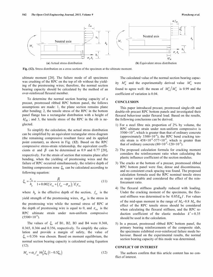
In contrast with an ordinary concrete flexural member, the effect of RPC tensile stress should be considered at the
542 The Open Civil Engineering Journal, 2015, Volume 9 Wenzhong et al.
ultimate moment [20]. The failure mode of all specimens was crushing of the RPC on the top of rib without the yield-ing of the prestressing wires; therefore, the normal section bearing capacity should be calculated by the method of an over-reinforced flexural member.
To determine the normal section bearing capacity of a
precast, prestressed ribbed RPC bottom panel, the follows
assumptions are made: 1, the plane section remains plane
after bending; 2, the tensile stress of the RPC in the bottom
panel flange has a rectangular distribution with a height of
tRkf ; and 3, the tensile stress of the RPC in the rib is ne-
glected.
To simplify the calculation, the actual stress distribution
can be simplified by an equivalent rectangular stress diagram
(the remaining compressive resultant force and its applied
point constant), as shown in Fig. (12). Based on the RPC
compressive stress-strain relationship, the equivalent coeffi-
cients and can be determined as 0.9 and 0.77 [20],
respectively. For the strain of section that remains plane after
bending, when the yielding of prestressing wires and the
failure of RPC occurred simultaneously, the relative depth of
limiting compression zone b
can be calculated according to
following equation:
b=
xb
hp
= 1
1+ 0.002cu+ f
py p0( ) Es cu
(11)
where ph is the effective depth of the section, pyf is the
yield strength of the prestressing wires, p0 is the stress in
the prestressing wire while the normal stress of RPC at
the depth of prestressing wire is equal to 0, and cu
is the
RPC ultimate strain under non-uniform compressive
(5500 10-6
).
The values of b
of B1, B2, B3 and B4 were 0.368,
0.365, 0.366 and 0.356, respectively. To simplify the calcu-
lation and provide a margin of safety, the value of
b0.356= was chosen. Based on moment equilibrium, the
normal section bearing capacity is calculated using Equation
(12).
Mu=
1fcR
bhp
2
b1 0.5
b( ) (12)
The calculated value of the normal section bearing capac-
ity c
uM and the experimentally derived value
t
uM were
found to agree well: the mean of c t
u uM M is 0.99 and the
coefficient of variation is 0.04.
CONCLUSION
This paper introduced precast, prestressed single-rib and double-rib precast RPC bottom panels and investigated their flexural behaviour under flexural load. Based on the results, the following conclusions can be derived.
1) For a steel fibre mix proportion of 2% by volume, the RPC ultimate strain under non-uniform compressive is 5500 10
-6, which is greater than that of ordinary concrete
(approximately 3300 10-6
); the RPC bend cracking ten-sile strain is 458 10
-6-577 10
-6, which is greater than
that of ordinary concrete (80 10-6
-120 10-6
).
2) The proposed calculation formula for cracking moment considers the reinforcement ratio when calculating the plastic influence coefficient of the section modulus.
3) The cracks at the bottom of a precast, prestressed ribbed RPC bottom panel were fine, dense and discontinuous, and no consistent crack spacing was found. The proposed calculation formula used the RPC nominal tensile stress as major variable and considered the effect of the rein-forcement ratio.
4) The flexural stiffness gradually reduced with loading.
Under the cracking moment of the specimens, the flex-
ural stiffness was determined to be R
0.85E I . For values
of the mid-span moment in the range of Mcr~0.8 Mu, the
effect of the RPC tensile stress should be considered
when calculating the flexural stiffness, and the RPC re-
duction coefficient of the elastic modulus 0.35k =
should be used in the calculation.
5) In a precast, prestressed ribbed RPC bottom panel, the primary bearing reinforcements of the composite slab, the specimens exhibited over-reinforced failure mode be-haviour. Based on the experimental results, the normal section bearing capacity of this mode was determined.
CONFLICT OF INTEREST
The authors confirm that this article content has no con-flict of interest.
(a) Actual stress distribution (b) Equivalent stress distribution
Fig. (12). Stress distribution on a cross section of the specimen at the ultimate moment.
Flexural Behaviour of Precast, Prestressed Ribbed RPC Bottom Panels The Open Civil Engineering Journal, 2015, Volume 9 543
ACKNOWLEDGEMENTS
Declared none.
REFERENCES
[1] A. A. Yee, and D. Hon. “Structural and economic benefits of pre-cast / presstressed concrete construction”, PCI Journal, vol. 46, pp.
34-42, 2001. [2] J.G. Hou, and C. X. He. “Composition plane behaviour of
prestressed composite slab”. Journal of WuHan University of Hy-draulic and Electrical Engineering, vol. 26, pp. 307-316, 1993.
[3] E.N.B.S. Julio, A. B. Fernando, B. V. D. Silva, “Concrete-to-concrete bond strength. Influence of the roughness of the substrate
surface,” Construction and Building Materials, vol. 18, pp. 675-681, 2004.
[4] A.I. Tenhovuori, and M.V. Leskela. “Longitudinal shear resistance of composite slab,” Construct Steel Research, vol. 46, pp. 238-245,
1998. [5] M Pentti, and Y Sun. “The longitudinal shear behaviour of a new
steel sheeting profile for composite floor slab,” Journal of Con-structional Steel Research, vol. 49, pp. 117-128, 1999.
[6] W.A. Thanoon, Y Yardim, M.S. Jaafar, and J. Noorzaei, “Struc-tural behaviour of ferrocement–brick composite floor slab panel,”
Construction and Building Materials, vol. 24, pp. 2224-2230, 2010. [7] Q.Q. Jiang, X.M. Wang, H.C. Liu, and S.C. Huang, “Calculation
method of composite slab with inverted-T bottom panel,” Journal of Central South University and Technology, vol. 34, pp. 567-570,
2003. [8] F.B. Wu, L Chen, and Y.M. Liu. “Experiment on prestressed con-
crete hollow-core composite slabs”. Journal of Architecture and Civil Engineering, vol. 25, pp. 88-92, 2008.
[9] F.B. Wu, H.L. Huang, W Chen, and X.H. Zhou. “Experimental analysis on the mechanical properties of concrete composite slabs
with precast prestressed rectangular rib panels”. Journal of Civil, Architectural & Environmental Engineering. vol. 33, pp. 7-12,
2011. [10] Y.X. Zhou, and F.P. Wang, “A research on the floor cover of rein-
forced concrete core clip plank with two-way dense ribs,” Journal of Nanhua University, vol. 19, pp. 91-95, 2005.
[11] P. Richard, and M. Cheyrezy, “Composition of reactive powder concretes," Cement and Concrete Research, vol. 25, pp. 1501-
1511, 1995.
[12] H Yazıcı, M Yücel, S. Aydın, and A. S. Karabulut, “Mechanical
properties of reactive powder concrete containing mineral admix-tures under different curing regimes,” Construction and Building
Materials, vol. 23, pp. 1223-1234, 2009. [13] A Cwirzen, V Penttala, and C Vornanen, “Reactive powder based
concretes: Mechanical properties, durability and hybrid use with OPC,” Cement and Concrete Research, vol. 38, pp. 1217-1226,
2008. [14] N. Roux, C. Andrade, and M.A. Sanjuan, “Experimental study of
durability of reactive powder concretes,” Journal of Materials in Civil Engineering, vol. 8, pp. 1-6, 1996.
[15] P.Y. Blais, and M. Couture, “Prestressed pedestrian bridge-world’s first reactive powder concrete structure,” PCI Journal, vol. 44, pp.
60-71, 1999. [16] C.J. Ao, “Conruction techniques of applying RPC precast units in
ex-tension of industrial building,” Shanxi Architecture, vol. 31, pp. 127-128, 2005.
[17] B.A. Tayeh, and B.H.A. Bakar, “Utilization of ultra-high perform-ance fibre concrete (UHPFC) for rehabilitation – a review,” Pro-
cedia Engineering, vol. 54, pp. 525-538, 2013. [18] A.K. Azad, and I.Y. Hakeem, “Flexural behavior of hybrid con-
crete beams reinforced with ultra-high performance concrete bars,” Construction and Building Materials, vol. 49, pp. 128-133, 2013.
[19] C.Y. Tian, and J.G. Nie, “Shear lag analysis of simply supported composite steel-concrete beams,” Journal of Tsinghua University.
vol. 45, pp. 1166-1169, 2005. [20] W.Z. Zheng, L. Li, and S.S. Lu, “Experimental research on me-
chanical performance of normal section of reinforced reactive powder concrete beam,” Journal of Building Structures, vol. 32,
pp. 125-134, 2011. [21] X.Y. Lu, Y. Wang, C.J. Fu, and W.Z. Zheng, “Basic mechanical
property indexes of reactive powder concrete,” Journal of Harbin Institute of Technology, vol. 46, pp. 1-9, 2014.
[22] Code for Design of Concrete Structures, 7 Vols. People’s Republic of China Ministry of Construction, Beijing: 2010.
[23] P. Gergely, and L.A. Lutz, “Maximum crack width in reinforced concrete flexural members,” ACI Journal. vol. SP-20, pp. 87-117,
1968. [24] E.G. Nawy, and P.T. Huang, “Crack and deflection control of pre-
tensioned prestressed beams”, PCI Journal, vol. 22, pp. 30-47, 1977.
Received: September 16, 2014 Revised: December 23, 2014 Accepted: December 31, 2014
© Wenzhong et al.; Licensee Bentham Open.
This is an open access article licensed under the terms of the Creative Commons Attribution Non-Commercial License (http://creativecommons.org/licenses/ by-nc/3.0/) which permits unrestricted, non-commercial use, distribution and reproduction in any medium, provided the work is properly cited.