Precast arch systems - holcim.com.au · was instrumented and design theories validated. ... a high...
25
Precast arch systems Issue 2
Transcript of Precast arch systems - holcim.com.au · was instrumented and design theories validated. ... a high...

Precast arch systemsIssue 2

Contents
Introduction and product development 2
Features and benefits 4
Asset owner 4
Consulting engineer 4
Contractor 4
End user 5
Details of arch elements 6
Standard arches 6
3-pin arches 8
Depth of fill 8
Footings 8
Hydraulics 9
Scour protection 14
End treatment 15
For arches with spans up to 12 m 15
Spandrel walls 15
Wing walls 16
Wing wall angle options 18
For arches with spans greater than 12 m 19
Spandrel walls 19
Wing walls 19
Multi-cell installations 21
Special installations 22
Contact information 23

Humes manufactures an extensive range of precast
concrete arch systems which may be used for bridges,
underpasses, tunnels, mine portals and drainage
culverts. The range of products available easily allows
for the adoption of standard units to provide a choice
of geometric envelopes to meet access and waterway
area requirements.
The elements of the Humes arch system are primarily:
• precast arch units
• precast spandrel walls
• precast wing walls.
The arches are installed on an in-situ concrete strip
foundation and are placed end-to-end to form the
desired structure length.
Where large expanses are to be crossed, for example a
flood plain, multiple arch spans are placed side by side
and provide an aesthetically pleasing structure.
The spandrel walls run parallel to the arch,
retaining the backfill at each end of the structure,
enhancing its appearance (refer to Figures 1 and 2 on the
following page).
Precast concrete wing walls, placed at each end of the
spandrel wall, not only retain the backfill and support
the spandrel walls but can also act as training walls
for waterways. All of these elements may be finished
in either conventional concrete or a variety of applied
finishes to suit the specific environment.
In 1984 Humes entered into an exclusive agreement
with BEBO Arch International AG (BEBO) for the
manufacture of BEBO® arches in Australia. Humes has a
commitment to technical excellence and consistent with
this it was mandatory to ensure the first arch installed
was instrumented and design theories validated.
Introduction and product development
Since that time Humes has undertaken development
work in consultation with the BEBO group and has
extended the BEBO concept into a unique portfolio
of arches which were initially marketed as the Classic
arch series.
When BEBO commenced operations the original arch
was developed from small flat slab elements, which
were joined together to form the arch profile, similar to a
block and keystone arrangement. This in turn led to the
one piece BEBO® arch. The ongoing development work at
Humes has produced a product range which consists of a
mix of one and two piece arches.
Humes continues to undertake the development
and refinement of the design methodology, using
both the original BEBO “finite displacement model”
and the more recently available design methodology
of “finite element analysis”, which was used to
confirm the designs of our Classic arch range. This
work ensures refinement to product design adopting
sound engineering practices and at the same time
ensuring compliance to Australasian Standards
and user specifications.
2 Precast arch systems

In both the installation of the first BEBO® arch and the
first Classic arch, Humes engaged Adelaide and Sydney
universities to fully instrument the structures and to
validate the design methodology and its suitability to
Australian conditions and requirements.
As the development work continues the soil structure
relationship for all arches will be defined using the finite
element methodology, which is more commonly used
in general engineering, and allows greater scope for the
analysis of structure response to site specific conditions.
All of Humes’ arches will continue to be offered as
either one or two piece elements. The number of
pieces is generally dependent on the span required, the
transportability of the pieces, or the loadings imposed
on the structure.
The naming convention for Humes’ arches is based on
horizontal span, vertical height and number of pieces.
The first number (or two numbers when the span is
10 metres or greater) is the span dimension expressed
in metres. The next three numbers are the height
expressed in centimetres. The final letter is either a “T”
for a two piece arch or an “S” for a one piece arch. For
example, an arch with an 18 m span and an internal
vertical height of 6 m designed in two pieces is an
18600T.
This convention reduces the risk of confusion between
our customers and sales consultants and then internally
between our sales, design and production centres.
See Table 1 – Standard arch data, on page 6 for details.
Figure 1 – General assembly, one piece arches
Figure 2 – General assembly, two piece arches
Arch units Spandrel wall
Wing wall
Width
Span
Rise
Rise
SpanWidth
Wing wall
Spandrel wallHalf arch units
Precast arch systems 3
Prec
ast
arch
sys
tem
s

Features and benefits
There are many benefits of using Humes’ precast arches to all stakeholders when
compared with conventional bridge or culvert construction. We have detailed these
by specific market sector and end use application.
• Hydraulic efficiency
The large span-to-height ratio for standard profiles
minimises hydraulic disturbance for wide low flow
streams and channels. Other profiles with various
span to height ratios can be supplied to accommodate
other stream or channel flow requirements.
• Versatility of profile
Several basic arch shapes and the option of using
multiple cell arches allows easy application to
most site configurations. Various spandrel wall and
wing wall options at the bridge ends compliment the
choice. Pedestal footings may be used if necessary to
increase headroom clearances.
Contractor
• Fast construction
Humes’ arches are simple to assemble which results
in very fast erection times. The ability to manufacture
and deliver the arches simultaneously with site
works reduces overall project time and allows quick
construction access across the spanned distance.
• Minimal waste
BEBO® and Classic arches only require simple
strip footings to resist vertical and horizontal
forces. No moment is transferred to the footings
simplifying their design and construction details.
Precast foundations are an option.
Asset owner
• Cost
The cost of the project is reduced by quick installation,
minimal design cost and low maintenance.
• Durability
The use of high strength concrete efficiently
compacted during manufacture at the factory ensures
a high strength durable product produced under a
stringent quality assurance system.
• Appearance
The graceful appearance of the arch complements
the environment and is aesthetically pleasing. Surface
treatment can be tailored to suit specific applications.
• Environmental impact
The arches can be sized to span most waterways
without midstream support thus preserving the
natural stream bed and providing a fish friendly
environment. Land based fauna requirements may
also be readily accommodated.
• Maintenance
The high quality concrete ensures a maintenance free
life with minimal inspections required by the owner
throughout the life of the structure.
Consulting engineer
• Structural design systems
All arches, spandrels and wing walls are designed by
Humes in accordance with the Australian Concrete
Structures Standard AS 3600 and AS 5100 - Bridge
Design. Humes can also advise on the design of the
cast in-situ strip footings.
4 Precast arch systems
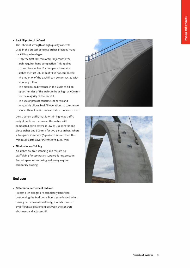
• Backfill protocol defined
The inherent strength of high quality concrete
used in the precast concrete arches provides many
backfilling advantages:
– Only the first 300 mm of fill, adjacent to the
arch, requires hand compaction. This applies
to one piece arches. For two piece in-service
arches the first 300 mm of fill is not compacted.
The majority of the backfill can be compacted with
vibratory rollers.
– The maximum difference in the levels of fill on
opposite sides of the arch can be as high as 600 mm
for the majority of the backfill.
– The use of precast concrete spandrels and
wing walls allows backfill operations to commence
sooner than if in-situ concrete structures were used.
Construction traffic that is within highway traffic
weight limits can cross over the arches with
compacted earth covers as low as 300 mm for one
piece arches and 500 mm for two piece arches. Where
a two piece in-service (3-pin) arch is used then this
minimum earth cover increases to 1,500 mm.
• Eliminates scaffolding
All arches are free standing and require no
scaffolding for temporary support during erection.
Precast spandrel and wing walls may require
temporary bracing.
End user
• Differential settlement reduced
Precast arch bridges are completely backfilled
overcoming the traditional bump experienced when
driving over conventional bridges which is caused
by differential settlement between the concrete
abutment and adjacent fill.
Precast arch systems 5
Prec
ast
arch
sys
tem
s
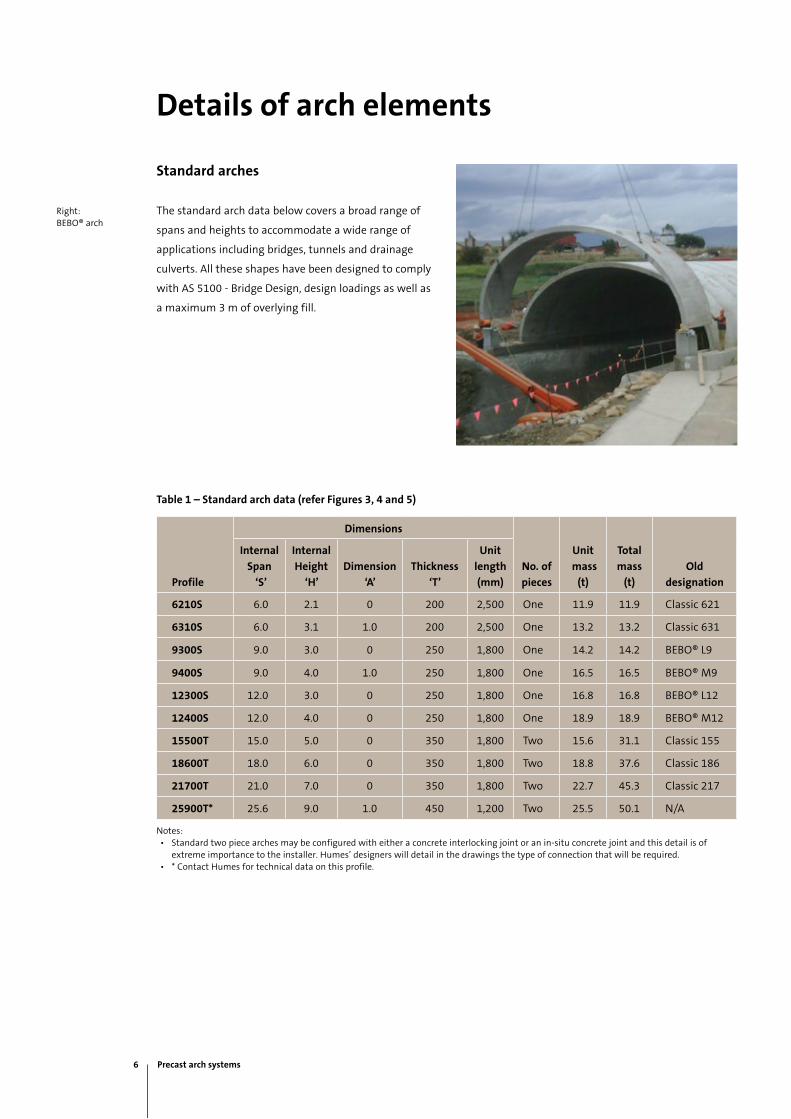
Right:BEBO® arch
Details of arch elements
Standard arches
The standard arch data below covers a broad range of
spans and heights to accommodate a wide range of
applications including bridges, tunnels and drainage
culverts. All these shapes have been designed to comply
with AS 5100 - Bridge Design, design loadings as well as
a maximum 3 m of overlying fill.
Table 1 – Standard arch data (refer Figures 3, 4 and 5)
Profile
Dimensions
No. of
pieces
Unit
mass
(t)
Total
mass
(t)
Old
designation
Internal
Span
‘S’
Internal
Height
‘H’
Dimension
‘A’
Thickness
‘T’
Unit
length
(mm)
6210S 6.0 2.1 0 200 2,500 One 11.9 11.9 Classic 621
6310S 6.0 3.1 1.0 200 2,500 One 13.2 13.2 Classic 631
9300S 9.0 3.0 0 250 1,800 One 14.2 14.2 BEBO® L9
9400S 9.0 4.0 1.0 250 1,800 One 16.5 16.5 BEBO® M9
12300S 12.0 3.0 0 250 1,800 One 16.8 16.8 BEBO® L12
12400S 12.0 4.0 0 250 1,800 One 18.9 18.9 BEBO® M12
15500T 15.0 5.0 0 350 1,800 Two 15.6 31.1 Classic 155
18600T 18.0 6.0 0 350 1,800 Two 18.8 37.6 Classic 186
21700T 21.0 7.0 0 350 1,800 Two 22.7 45.3 Classic 217
25900T* 25.6 9.0 1.0 450 1,200 Two 25.5 50.1 N/A
Notes:• Standard two piece arches may be configured with either a concrete interlocking joint or an in-situ concrete joint and this detail is of
extreme importance to the installer. Humes’ designers will detail in the drawings the type of connection that will be required.• * Contact Humes for technical data on this profile.
6 Precast arch systems
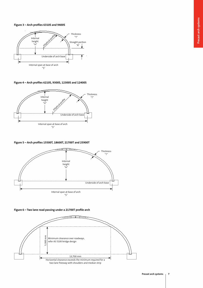
Figure 3 – Arch profiles 6310S and 9400S
Precast arch systems 7
Prec
ast
arch
sys
tem
s
Figure 4 – Arch profiles 6210S, 9300S, 12300S and 12400S
Figure 5 – Arch profiles 15500T, 18600T, 21700T and 25900T
Figure 6 – Two lane road passing under a 21700T profile arch
Thickness“T”
Straight portion“A”Ellip
tical p
rofile
Internal span at base of arch“S”
Underside of arch base
Internalheight
“H”
Thickness“T”
Underside of arch base
Internal span at base of arch“S”
5,30
0 m
m
Minimum clearance over roadways, refer AS 5100 bridge design
Horizontal clearance exceeds the minimum required for a two lane freeway with shoulders and median strip
13,700 mm
Internalheight
“H”
Internalheight
“H”
Underside of arch base
Thickness“T”
Elliptic
al pro
file
Internal span at base of arch“S”
Depth of fill
The minimum depth of fill required over the crown is
0.3 m for BEBO® arches, 0.5 m for Classic arches and up
to 1.5 m for 3-pin arches.
For standard BEBO® and Classic arches the maximum
depth of compacted fill is 3 to 5 m, at 21 kN/ cu.m.
Larger fill heights (up to 50 m) have been achieved
for coal stockpiles and other lighter materials.
Our engineers should be consulted where fill heights
are in excess of the maximum nominated depth for
standard units. In these cases project specific designs
will be recommended.
Footings
BEBO® and Classic arches are designed to act in service
as structures with pinned base supports. The hinge at
the foundation is achieved by providing a keyway into
which the arches are placed. This keyway is then grouted
to form a lateral restrained pin connection.
Actual rotations at the hinge are very small during
backfilling operations and for all practical purposes zero
once backfilling is complete. There are essentially no
special requirements when designing footings for BEBO®
and Classic arch structures. Where underlying soils do
not have adequate bearing capacity the structure may
be supported by piles. Humes will provide advice on the
footing reaction for the design and should always be
consulted during the early design stages.
Final footing design is the responsibility of the project
structural engineer. Humes are able to supply precast
concrete footings if the designer wants to consider
this option.
Humes can provide specific advice where greater fill
depth or user defined live loads are encountered such as
railway and heavy construction equipment.
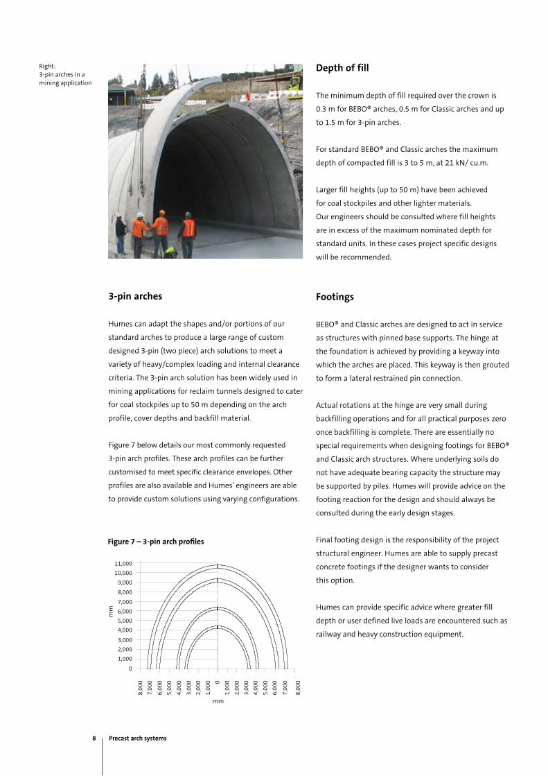
3-pin arches
Humes can adapt the shapes and/or portions of our
standard arches to produce a large range of custom
designed 3-pin (two piece) arch solutions to meet a
variety of heavy/complex loading and internal clearance
criteria. The 3-pin arch solution has been widely used in
mining applications for reclaim tunnels designed to cater
for coal stockpiles up to 50 m depending on the arch
profile, cover depths and backfill material.
Figure 7 below details our most commonly requested
3-pin arch profiles. These arch profiles can be further
customised to meet specific clearance envelopes. Other
profiles are also available and Humes’ engineers are able
to provide custom solutions using varying configurations.
Figure 7 – 3-pin arch profiles
11,000
10,000
9,000
8,000
7,000
6,000
5,000
4,000
3,000
2,000
1,000
0
8,00
0
7,00
0
6,00
0
5,00
0
5,00
0
6,00
0
7,00
0
8,00
0
4,00
0
4,00
0
3,00
0
3,00
0
2,00
0
2,00
0
1,00
0
1,00
00
Right:3-pin arches in a mining application
mm
mm
8 Precast arch systems
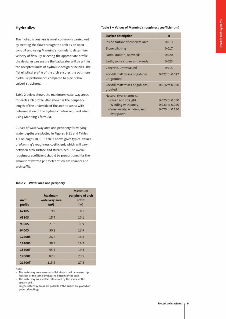
Table 3 – Values of Manning’s roughness coefficient (n)
Surface description n
Inside surface of concrete arch 0.013
Stone pitching 0.017
Earth, smooth, no weeds 0.020
Earth, some stones and weeds 0.025
Concrete, untrowelled 0.015
Rockfill mattresses or gabions,
un-grouted
0.022 to 0.027
Rockfill mattresses or gabions,
grouted
0.016 to 0.020
Natural river channels:
– Clean and straight
– Winding with pools
– Very weedy, winding and
overgrown
0.025 to 0.030
0.033 to 0.040
0.075 to 0.150
Hydraulics
The hydraulic analysis is most commonly carried out
by treating the flow through the arch as an open
conduit and using Manning’s formula to determine
velocity of flow. By selecting the appropriate profile
the designer can ensure the backwater will be within
the accepted limits of hydraulic design principles. The
flat elliptical profile of the arch ensures the optimum
hydraulic performance compared to pipe or box
culvert structures.
Table 2 below shows the maximum waterway areas
for each arch profile. Also shown is the periphery
length of the underside of the arch to assist with
determination of the hydraulic radius required when
using Manning’s formula.
Curves of waterway area and periphery for varying
water depths are plotted in Figures 8-11 and Tables
4-7 on pages 10-13. Table 3 above gives typical values
of Manning’s roughness coefficient, which will vary
between arch surface and stream bed. The overall
roughness coefficient should be proportioned for the
amount of wetted perimeter of stream channel and
arch soffit.
Table 2 – Water area and periphery
Arch
profile
Maximum
waterway area
(m2)
Maximum
periphery of arch
soffit
(m)
6210S 9.9 8.1
6310S 15.9 10.1
9300S 21.2 11.9
9400S 30.2 13.9
12300S 26.7 14.2
12400S 38.9 16.2
15500T 55.5 19.3
18600T 82.5 23.5
21700T 115.5 27.8
Notes:• The waterway area assumes a flat stream bed between strip
footings at the same level as the bottom of the arch.• The waterway area will be influenced by the shape of the
stream bed.• Larger waterway areas are possible if the arches are placed on
pedestal footings.
Precast arch systems 9
Prec
ast
arch
sys
tem
s

Figure 8 – Hydraulic curves for BEBO® arches (waterway area)
2.2 12.786 17.844 22.622 19.505 25.824
2.4 13.728 18.998 24.022 21.126 27.852
2.6 14.566 19.991 25.220 22.685 29.786
2.8 15.269 20.772 26.157 24.167 31.615
3.0 15.773 21.206 26.675 25.560 33.320
3.1 15.896
3.2 26.844 34.887
3.4 27.998 36.286
3.6 28.991 37.484
3.8 29.772 38.421
4.0 30.206 38.940
Note:Graphs do not include the wetted perimeter of the stream bed.
Table 4 – (See Figure 8)
Depth
(m)
Waterway area
(m2)
Arch
6210S
Arch
6310S
Arch
9300S
Arch
12300S
Arch
9400S
Arch
12400S
0.2 1.198 1.200 1.799 2.383 1.800 2.478
0.4 2.385 2.400 3.589 4.727 3.600 4.950
0.6 3.550 3.600 5.364 7.025 5.400 7.409
0.8 4.681 4.800 7.114 9.269 7.200 9.849
1.0 5.765 6.000 8.830 11.450 9.000 12.265
1.2 6.786 7.198 10.505 13.559 10.799 14.648
1.4 7.728 8.385 12.126 15.587 12.589 16.992
1.6 8.566 9.550 13.685 17.522 14.364 19.290
1.8 9.268 10.681 15.167 19.350 16.114 21.533
2.0 9.773 11.765 16.560 21.057 17.830 23.714
Wat
er d
epth
ab
ove
bas
e of
arc
h (m
)
Waterway area (m2) for level stream bed
4035302520151050
4.5
4.0
3.5
3.0
2.5
2.0
1.5
1.0
0.5
12400S
12300S
6210S
9400S
6310S 9300S
10 Precast arch systems

Figure 9 – Hydraulic curves for BEBO® arches (wetted perimeter)
Table 5 – (See Figure 9)
Depth
(m)
Wetted perimeter
(m)
Arch
6210S
Arch
6310S
Arch
9300S
Arch
12300S
Arch
9400S
Arch
12400S
0.2 0.400 0.400 0.400 0.438 0.400 0.400
0.4 0.810 0.800 0.806 0.890 0.800 0.804
0.6 1.234 1.200 1.218 1.364 1.200 1.210
0.8 1.683 1.600 1.644 1.858 1.600 1.626
1.0 2.166 2.000 2.086 2.380 2.000 2.050
1.2 2.700 2.402 2.550 2.934 2.400 2.488
1.4 3.303 2.810 3.044 3.524 2.806 2.942
1.6 4.013 3.234 3.574 4.162 3.218 3.414
1.8 4.905 3.682 4.150 4.858 3.644 3.908
2.0 6.229 4.166 4.784 5.624 4.086 4.430
2.2 4.700 5.496 6.484 4.550 4.984
2.4 5.304 6.318 7.476 5.044 5.576
2.6 6.014 7.314 8.672 5.574 6.214
2.8 6.904 8.634 10.256 6.150 6.908
3.0 8.230 11.899 14.155 6.784 7.674
3.1 10.074
3.2 7.496 8.534
3.4 8.318 9.526
3.6 9.314 10.722
3.8 10.634 12.306
4.0 13.899 16.205
Wat
er d
epth
ab
ove
bas
e of
arc
h (m
)
Wetted perimeter of arch soffit (m)
4.5
4.0
3.5
3.0
2.5
2.0
1.5
1.0
0.5
181614121086420
9400S
9300S6310S
6210S
12400S
12300S
Precast arch systems 11
Prec
ast
arch
sys
tem
s

Figure 10 – Hydraulic curves for Classic arches (waterway area)
Table 6 – (See Figure 10)
Depth
(m)
Waterway area
(m2)
Arch
15500T
Arch
18600T
Arch
21700T
0.2 2.991 3.597 4.199
0.4 5.963 7.184 8.395
0.6 8.190 10.755 12.585
0.8 11.828 14.272 16.763
1.0 14.715 17.838 20.928
1.2 17.565 21.342 25.076
1.4 20.374 24.816 29.203
1.6 23.138 28.256 33.305
1.8 25.850 31.658 37.379
2.0 28.507 35.018 41.421
2.2 31.102 38.331 45.428
2.4 33.630 41.592 49.394
2.6 36.083 44.797 53.317
2.8 38.455 47.940 57.192
3.0 40.738 51.016 61.014
3.1
3.2 42.923 54.018 64.780
3.4 45.000 56.942 68.484
3.6 46.957 59.779 72.121
3.8 48.781 62.522 75.686
4.0 50.456 65.163 79.173
Depth
(m)
Waterway area
(m2)
Arch
15500T
Arch
18600T
Arch
21700T
4.2 51.961 67.692 82.577
4.4 53.270 70.099 85.891
4.6 54.344 72.372 89.108
4.8 55.123 74.497 92.220
5.0 55.465 76.456 95.219
5.2 78.227 98.096
5.4 79.782 100.839
5.6 81.097 103.436
5.8 82.048 105.873
6.0 82.515 108.133
6.2 110.192
6.4 112.021
6.6 113.577
6.8 114.787
7.0 115.454
Note: Graphs do not include the wetted perimeter of the stream bed.
Wat
er d
epth
ab
ove
bas
e of
arc
h (m
)
Waterway area (m2) for level stream bed
0 40 120110100
9.0
10 20 30 50 60 70 80 90
0.5
1.0
1.5
2.0
2.5
3.0
3.5
4.0
4.5
5.0
5.5
6.0
6.5
7.0
7.5
8.0
8.5
15500T
18600T
21700T
12 Precast arch systems
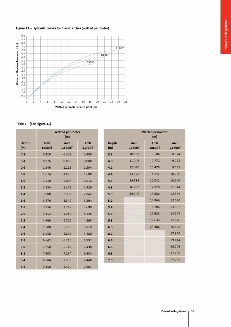
Figure 11 – Hydraulic curves for Classic arches (wetted perimeter)
Table 7 – (See Figure 11)
Depth
(m)
Wetted perimeter
(m)
Arch
15500T
Arch
18600T
Arch
21700T
0.2 0.410 0.402 0.400
0.4 0.826 0.808 0.800
0.6 1.246 1.218 1.204
0.8 1.674 1.630 1.608
1.0 2.110 2.048 2.016
1.2 2.554 2.472 2.426
1.4 3.008 2.902 2.842
1.6 3.476 3.340 3.264
1.8 3.956 3.788 3.690
2.0 4.452 4.246 4.126
2.2 4.966 4.716 4.568
2.4 5.500 5.200 5.018
2.6 6.058 5.696 5.480
2.8 6.642 6.210 5.952
3.0 7.258 6.742 6.438
3.2 7.908 7.294 6.934
3.4 8.604 7.906 7.448
3.6 9.350 8.472 7.967
Depth
(m)
Wetted perimeter
(m)
Arch
15500T
Arch
18600T
Arch
21700T
3.8 10.158 9.104 8.524
4.0 11.046 9.772 9.092
4.2 12.040 10.478 9.682
4.4 13.178 11.232 10.296
4.6 14.534 12.042 10.940
4.8 16.292 12.920 11.614
5.0 19.308 13.886 12.326
5.2 14.966 13.080
5.4 16.204 13.882
5.6 17.688 14.744
5.8 19.634 15.676
6.0 23.486 16.698
6.2 17.840
6.4 19.144
6.6 20.706
6.8 22.760
7.0 27.765
Wat
er d
epth
ab
ove
bas
e of
arc
h (m
)
Wetted perimeter of arch soffit (m)
9.08.58.07.57.0
282624222018161412106420 8
6.5
4.0
6.0
3.5
5.5
3.0
5.0
2.5
4.5
2.01.51.00.5
21700T
18600T
15500T
Precast arch systems 13
Prec
ast
arch
sys
tem
s

Table 8 – Maximum recommended flow velocities for
various materials
Material
Maximum velocity
(m/s)
Arch soffit 8.0
In-situ concrete 6.0
Hard packed rock
(300 mm minimum size)
6.0
Beaching or boulders
(250 mm minimum size)
5.0
Stones (100-150 mm size) 3.0
Grass covered surface 1.8
Coarse gravel 1.8
Stiff, sand clay 1.5
Coarse sand 0.7
Fine sand 0.5
Top:Arches subjected to high flows require scour protection
Bottom:BEBO® arch on concrete strip footing
Scour protection
Often BEBO® and Classic arches are used to span
waterways and are subjected to the dynamic forces of
rapidly flowing water. It is essential that the designer
not only considers hydraulic criteria but the probability
of scour caused by turbulent flow conditions.
BEBO® and Classic arches are normally founded
on concrete strip footings. The probability of scour
therefore becomes an important consideration in the
overall design.
Absolute velocities beyond which erosion will occur
are difficult to determine due to unknown variables
such as the amount and nature of debris discharged and
frequency of peak velocity. However, commonly adopted
values based on experience are listed in Table 8.
Where underlying soils do not have adequate
bearing the BEBO® and Classic arch structures may
be supported on piles, in which case scour is less of a
potential problem.
14 Precast arch systems
End treatment
Precast concrete spandrel walls and wing walls can be provided at the ends
of BEBO® and Classic arches to retain the backfill. In waterway crossings the
wing walls assist in training the water through the arch and reduce entrance losses.
For arches with spans up to 12 m
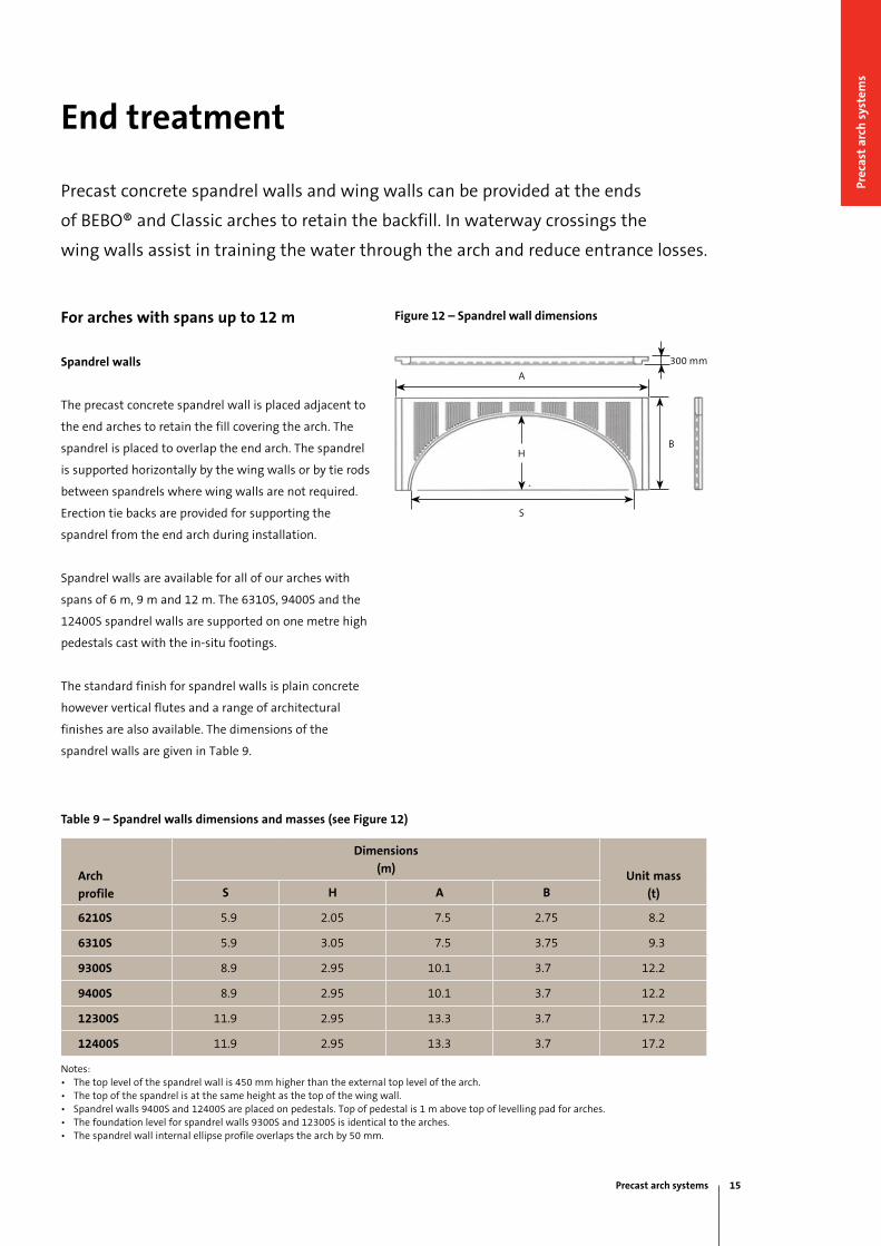
Spandrel walls
The precast concrete spandrel wall is placed adjacent to
the end arches to retain the fill covering the arch. The
spandrel is placed to overlap the end arch. The spandrel
is supported horizontally by the wing walls or by tie rods
between spandrels where wing walls are not required.
Erection tie backs are provided for supporting the
spandrel from the end arch during installation.
Spandrel walls are available for all of our arches with
spans of 6 m, 9 m and 12 m. The 6310S, 9400S and the
12400S spandrel walls are supported on one metre high
pedestals cast with the in-situ footings.
The standard finish for spandrel walls is plain concrete
however vertical flutes and a range of architectural
finishes are also available. The dimensions of the
spandrel walls are given in Table 9.
Table 9 – Spandrel walls dimensions and masses (see Figure 12)
Arch
profile
Dimensions
(m)Unit mass
(t)S H A B
6210S 5.9 2.05 7.5 2.75 8.2
6310S 5.9 3.05 7.5 3.75 9.3
9300S 8.9 2.95 10.1 3.7 12.2
9400S 8.9 2.95 10.1 3.7 12.2
12300S 11.9 2.95 13.3 3.7 17.2
12400S 11.9 2.95 13.3 3.7 17.2
Notes:• The top level of the spandrel wall is 450 mm higher than the external top level of the arch.• The top of the spandrel is at the same height as the top of the wing wall.• Spandrel walls 9400S and 12400S are placed on pedestals. Top of pedestal is 1 m above top of levelling pad for arches.• The foundation level for spandrel walls 9300S and 12300S is identical to the arches.• The spandrel wall internal ellipse profile overlaps the arch by 50 mm.
Figure 12 – Spandrel wall dimensions
300 mm
B
A
H
S
Precast arch systems 15
Prec
ast
arch
sys
tem
s
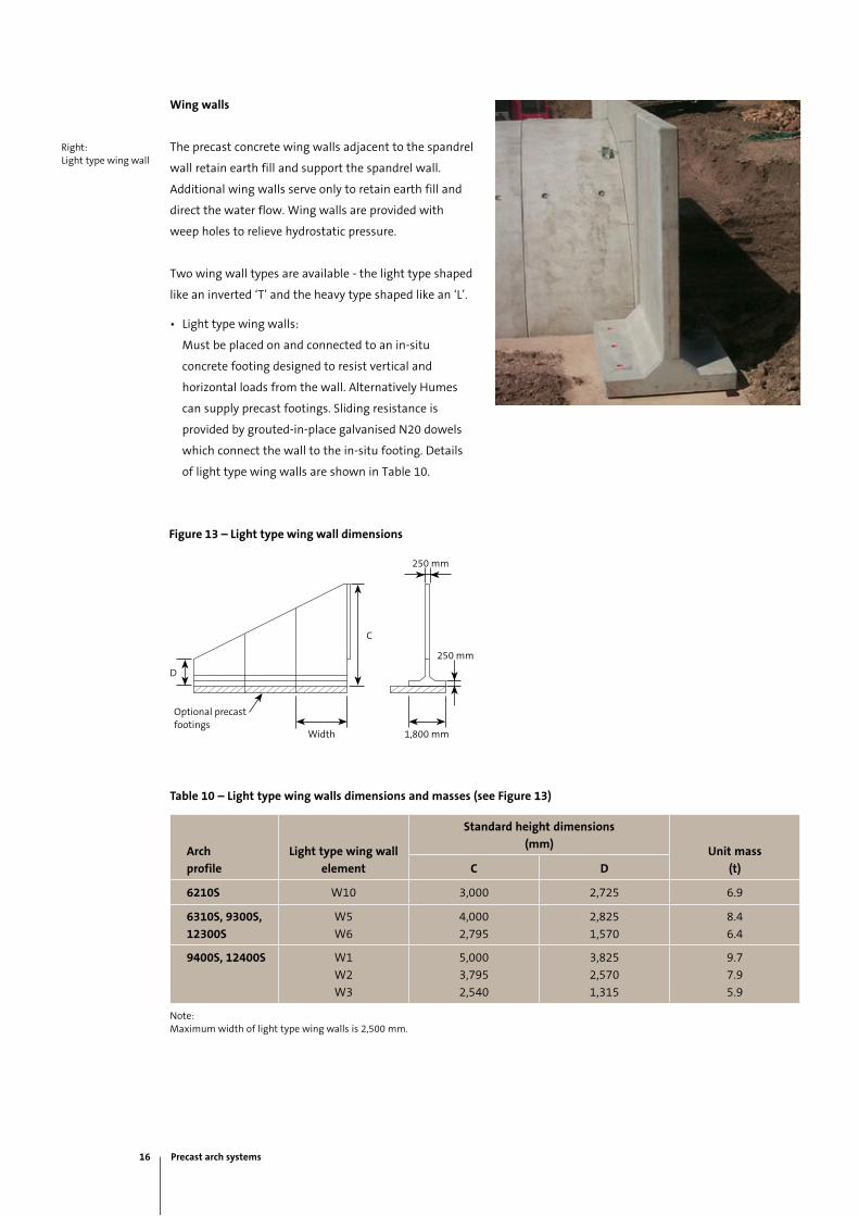
Wing walls
The precast concrete wing walls adjacent to the spandrel
wall retain earth fill and support the spandrel wall.
Additional wing walls serve only to retain earth fill and
direct the water flow. Wing walls are provided with
weep holes to relieve hydrostatic pressure.
Two wing wall types are available - the light type shaped
like an inverted ‘T’ and the heavy type shaped like an ‘L’.
• Light type wing walls:
Must be placed on and connected to an in-situ
concrete footing designed to resist vertical and
horizontal loads from the wall. Alternatively Humes
can supply precast footings. Sliding resistance is
provided by grouted-in-place galvanised N20 dowels
which connect the wall to the in-situ footing. Details
of light type wing walls are shown in Table 10.
Table 10 – Light type wing walls dimensions and masses (see Figure 13)
Arch
profile
Light type wing wall
element
Standard height dimensions
(mm)Unit mass
(t)C D
6210S W10 3,000 2,725 6.9
6310S, 9300S,
12300S
W5
W6
4,000
2,795
2,825
1,570
8.4
6.4
9400S, 12400S W1
W2
W3
5,000
3,795
2,540
3,825
2,570
1,315
9.7
7.9
5.9
Note:Maximum width of light type wing walls is 2,500 mm.
Figure 13 – Light type wing wall dimensions
Right:Light type wing wall
250 mm
D
250 mm
1,800 mmWidth
Optional precast footings
C
16 Precast arch systems

Figure 14 – Heavy type wing wall dimensions
• Heavy type wing walls:
Designed to resist overturning and sliding without
reliance on an in-situ footing. Typically they are placed
on compacted gravel material 500 mm thick and
the top surface levelled with a 50 mm thick blinding
layer of 15 MPa concrete. The bearing pressure
needs to be checked to ensure the foundation has
adequate capacity. Typically a foundation capacity of
250 kPa is required to accommodate working loads.
Dimensions of heavy type wing walls are given in
Table 11. Note that the assessment of the strength
and settlement potential of the foundation material
and global stability is the responsibility of the client’s
geotechnical engineer.
Table 11 – Heavy type wing walls dimensions and masses (see Figure 14)
Arch
profile
Heavy type wing wall
element
Standard height dimensions
(mm)Unit mass*
(t)C D
9300S, 1200S HL1
HL2
4,000
2,795
2,825
1,570
11.3
9.6
9400S, 12400S HM1
HM2
HM3
5,000
3,795
2,540
3,825
2,570
1,315
13.3
11.5
9.1
Notes:• Maximum width of heavy type wing walls is 2,500 mm.• *Unit mass based on 2,250 mm base.• For wing wall heights greater than 5 m, contact your local Humes sales representative.
Left:Heavy type wing wall
D
Width 2,250 mm min
C
300 mm
400 mm
Precast arch systems 17
Prec
ast
arch
sys
tem
s

Top:120° wing wall
Bottom:180° wing wall
Wing wall angle options
Wing walls can be placed at 90°, 120° or 180° to the
spandrel face. It is possible for a structure to have a
combination of wing wall angles to suit the geometry
of the stream bed.
180° wing walls run parallel to the spandrel wall and
hence do not support the wall. To overcome this, the
spandrel walls are restrained by tie rods spanning
across the structure. This method of construction
is also used when precast spandrels are used
without precast wing walls.
Typically wing walls running at a skew angle to road
alignment are not subject to roadway traffic loading.
As a result standard wing wall designs do not consider
roadway loadings.
Where wing walls are to run parallel with the
roadway (180°) our engineers need to be advised so that
roadway loads can be considered and the standard wing
walls evaluated for the suitability of application.
18 Precast arch systems
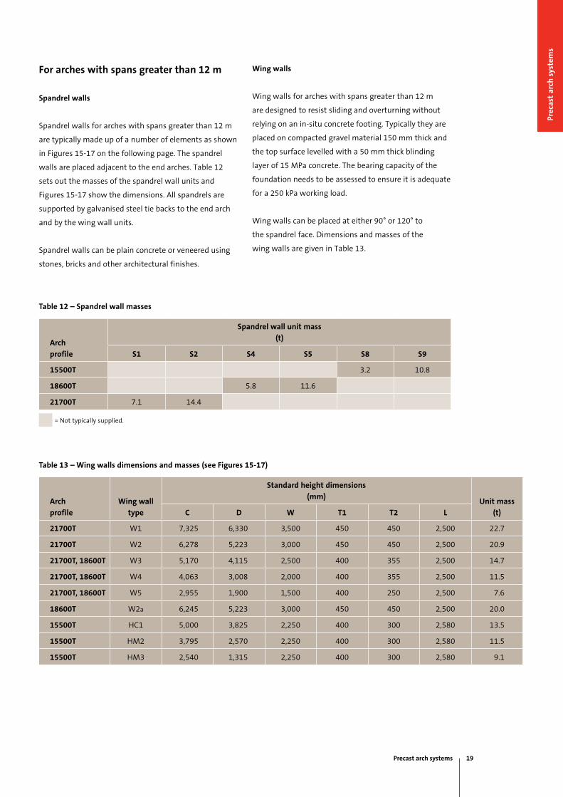
Wing walls
Wing walls for arches with spans greater than 12 m
are designed to resist sliding and overturning without
relying on an in-situ concrete footing. Typically they are
placed on compacted gravel material 150 mm thick and
the top surface levelled with a 50 mm thick blinding
layer of 15 MPa concrete. The bearing capacity of the
foundation needs to be assessed to ensure it is adequate
for a 250 kPa working load.
Wing walls can be placed at either 90° or 120° to
the spandrel face. Dimensions and masses of the
wing walls are given in Table 13.
For arches with spans greater than 12 m
Spandrel walls
Spandrel walls for arches with spans greater than 12 m
are typically made up of a number of elements as shown
in Figures 15-17 on the following page. The spandrel
walls are placed adjacent to the end arches. Table 12
sets out the masses of the spandrel wall units and
Figures 15-17 show the dimensions. All spandrels are
supported by galvanised steel tie backs to the end arch
and by the wing wall units.
Spandrel walls can be plain concrete or veneered using
stones, bricks and other architectural finishes.
Table 13 – Wing walls dimensions and masses (see Figures 15-17)
Arch
profile
Wing wall
type
Standard height dimensions
(mm)Unit mass
(t)C D W T1 T2 L
21700T W1 7,325 6,330 3,500 450 450 2,500 22.7
21700T W2 6,278 5,223 3,000 450 450 2,500 20.9
21700T, 18600T W3 5,170 4,115 2,500 400 355 2,500 14.7
21700T, 18600T W4 4,063 3,008 2,000 400 355 2,500 11.5
21700T, 18600T W5 2,955 1,900 1,500 400 250 2,500 7.6
18600T W2a 6,245 5,223 3,000 450 450 2,500 20.0
15500T HC1 5,000 3,825 2,250 400 300 2,580 13.5
15500T HM2 3,795 2,570 2,250 400 300 2,580 11.5
15500T HM3 2,540 1,315 2,250 400 300 2,580 9.1
Table 12 – Spandrel wall masses
Arch
profile
Spandrel wall unit mass
(t)
S1 S2 S4 S5 S8 S9
15500T 3.2 10.8
18600T 5.8 11.6
21700T 7.1 14.4
= Not typically supplied.
Precast arch systems 19
Prec
ast
arch
sys
tem
s
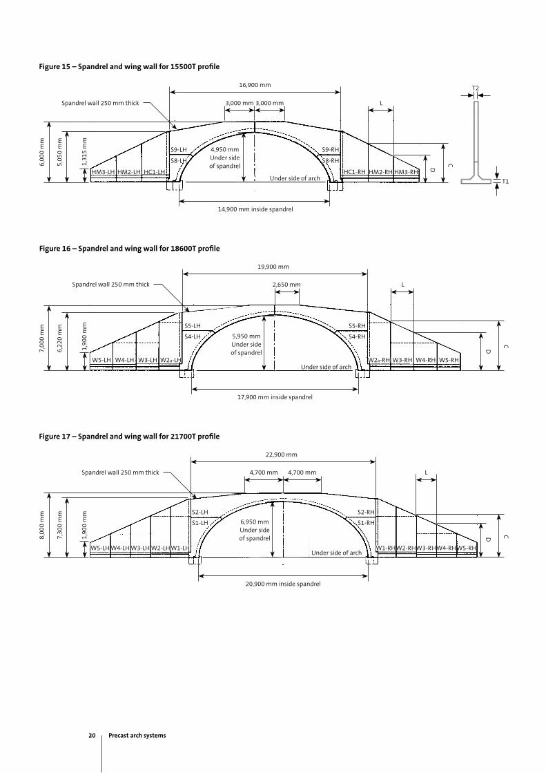
Figure 15 – Spandrel and wing wall for 15500T profile
Figure 16 – Spandrel and wing wall for 18600T profile
Figure 17 – Spandrel and wing wall for 21700T profile
T2
T1
6,00
0 m
m
5,05
0 m
m
C
D
Spandrel wall 250 mm thick
14,900 mm inside spandrel
L
S9-RHS9-LH
S8-RHS8-LH
4,950 mm Under side of spandrel
HM3-LH HM3-RHHM2-LH HM2-RHHC1-LH HC1-RH
16,900 mm
3,000 mm 3,000 mm
Under side of arch
7,00
0 m
m
6,22
0 m
m
Spandrel wall 250 mm thick L
19,900 mm
2,650 mm
17,900 mm inside spandrel
W5-RHW4-RHW3-RHW2a-RHW5-LH W4-LH W3-LH W2a-LH
S5-RHS5-LH
S4-RHS4-LH 5,950 mm Under side of spandrel
C
D
CD8,00
0 m
m
7,30
0 m
m
1,90
0 m
m1,
900
mm
1,31
5 m
m
Spandrel wall 250 mm thick L
22,900 mm
4,700 mm 4,700 mm
W5-RHW4-RHW3-RHW2-RHW1-RHW5-LH W4-LH W3-LH W2-LH W1-LH
6,950 mm Under side of spandrel
20,900 mm inside spandrel
S2-RHS2-LH
S1-RHS1-LH
Under side of arch
Under side of arch
20 Precast arch systems

Multi-cell installations
Double, triple or multiple cell installations can be
constructed to cross large expanses of water, flood plains
or low lying ground. It is possible to combine BEBO®
arches with Classic arches in multiple installations.
The support of the centre spandrel walls in multiple
installations is achieved by using galvanised steel tie
rods connecting opposite end spandrels to each other.
This is identical to the spandrel support recommended
for 180° wing walls. Alternatively, tie bars raked back to
the in-situ footing may be used.
Top:Combination of Classic and BEBO® arches
Bottom:Multi-cell BEBO® structure
Precast arch systems 21
Prec
ast
arch
sys
tem
s

Special installations
Figure 19 – Concept for 3-pin arch railway tunnel
Often customer requirements result in special
installations. Humes can offer advice and provide
practical solutions to the special needs of the customer.
An example of a non-standard installation is shown in
Figure 19.
Top:Mitred BEBO® arches to accommodate a skewed application
6,20
0 m
m
Railway clearance envelope
5,560 mm
250 mm
22 Precast arch systems

National sales 1300 361 601
humes.com.au
Contact information
Tasmania
Launceston
Ph: (03) 6335 6300
Fax: (03) 6335 6330
South Australia
Adelaide
Ph: (08) 8168 4544
Fax: (08) 8168 4549
Western Australia
Gnangara
Ph: (08) 9302 8000
Fax: (08) 9309 1625
Perth
Ph: (08) 9351 6999
Fax: (08) 9351 6977
Northern Territory
Darwin
Ph: (08) 8984 1600
Fax: (08) 8984 1614
Head Office
18 Little Cribb St
Milton QLD 4064
Ph: (07) 3364 2800
Fax: (07) 3364 2963
Queensland
Ipswich/Brisbane
Ph: (07) 3814 9000
Fax: (07) 3814 9014
Rockhampton
Ph: (07) 4924 7900
Fax: (07) 4924 7901
Townsville
Ph: (07) 4758 6000
Fax: (07) 4758 6001
New South Wales
Grafton
Ph: (02) 6644 7666
Fax: (02) 6644 7313
Newcastle
Ph: (02) 4032 6800
Fax: (02) 4032 6822
Sydney
Ph: (02) 9832 5555
Fax: (02) 9625 5200
Tamworth
Ph: (02) 6763 7300
Fax: (02) 6763 7301
Victoria
Echuca
Ph: (03) 5480 2371
Fax: (03) 5482 3090
Melbourne
Ph: (03) 9360 3888
Fax: (03) 9360 3887

FSC logo here
This publication supersedes all previous literature on this subject. As the specifications and details contained in this publication may change please check with Humes Customer Service for confirmation of current issue. This publication provides general information only and is no substitute for professional engineering advice. No representation or warranties are made regarding the accuracy, completeness or relevance of the information provided. Users must make their own determination as to the suitability of this information or any Humes’ product for their specific circumstances. All measurements and physical properties quoted are approximate values only and can vary. Drawings are not to scale. Humes accepts no liability for any loss or damage resulting from any reliance on the information provided in this publication. Humes is a registered business name and registered trademark of Holcim (Australia) Pty Ltd (Holcim). “Strength. Performance. Passion.” is a trademark of Holcim. BEBO is a registered trademark of BEBO Arch International AG.
© June 2015 Holcim (Australia) Pty Ltd ABN 87 099 732 297. All rights reserved. This guide or any part of it may not be reproduced without prior written consent of Holcim.
National sales 1300 361 601
humes.com.au
A Division of Holcim Australia