Practical Thermal Imaging Applications - … Thermal Imaging Applications ... •Infrared radiation...
97
Fluke Thermal Imaging Company Confidential 1 Practical Thermal Imaging Applications Understanding our Thermal World Marcus Thomas NW Territory Sales Engineer
Transcript of Practical Thermal Imaging Applications - … Thermal Imaging Applications ... •Infrared radiation...

Fluke Thermal Imaging Company Confidential 1
Practical Thermal Imaging Applications
Understanding our Thermal World
Marcus Thomas NW Territory Sales Engineer
Fluke Thermal Imaging Company Confidential 2
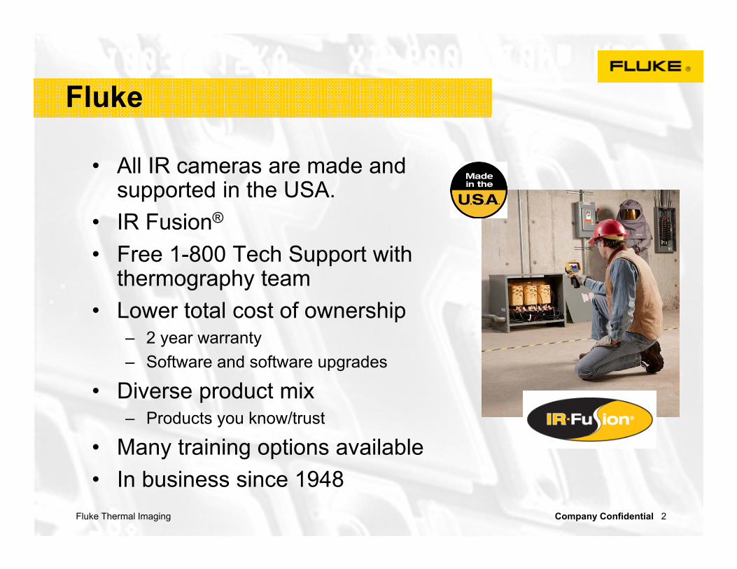
Fluke
• All IR cameras are made and supported in the USA.
• IR Fusion®
• Free 1-800 Tech Support with thermography team
• Lower total cost of ownership– 2 year warranty– Software and software upgrades
• Diverse product mix– Products you know/trust
• Many training options available• In business since 1948

Fluke Thermal Imaging Company Confidential 3
Overview of ThermographyKnowing a little about thermography helps!

Fluke Thermal Imaging Company Confidential 4
What is Thermography?
• It is the science of “seeing” temperatures by measuring the radiation emitted from an objects surface and converting this data to a corresponding digital, or visual image showing temperature
• Infrared radiation is emitted by all objects based on their temperature
– The amount of radiation increases with temperature
• We are only measuring the surface temperature!

Fluke Thermal Imaging Company Confidential 5
Why use Thermal Imaging?
•Hot or cold areas, or thermal anomalies, often are a strong indicator of equipment health
•Thermal Imaging works well to inspect:– Electrical Equipment– Electrical Circuits– Mechanical Equipment– Heating/Cooling Equipment– Building Envelope– Electronic circuits and boards– Other!

Fluke Thermal Imaging Company Confidential 6
Other!

Fluke Thermal Imaging Company Confidential 7
Temperature Measurements
•Fast, safe and accurate non-contact measurements can be obtained from objects even if the are:
– moving or very hot– contaminated or altered if contacted– difficult to reach – expensive to shut-down– dangerous to contact

Fluke Thermal Imaging Company Confidential 8
Spot Size
•Spot Size is the area on target seen by single detector similar to IFOV
– Expressed as a ratio, like 50:1 which means at 50 ft the measurement spot on the target is 1ft square
1 ft.
50 feet 50:1
Fluke Thermal Imaging Company Confidential 9
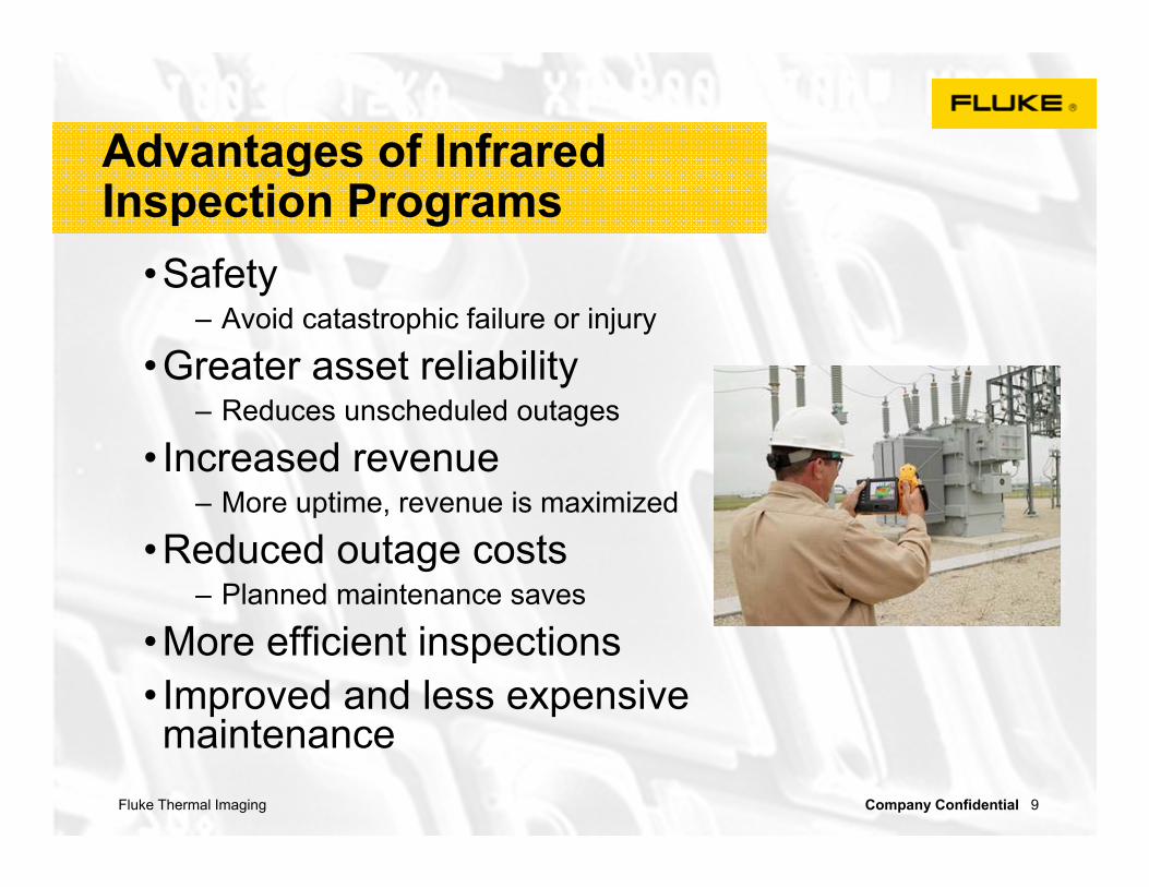
Advantages of Infrared Inspection Programs
•Safety– Avoid catastrophic failure or injury
•Greater asset reliability– Reduces unscheduled outages
• Increased revenue– More uptime, revenue is maximized
•Reduced outage costs– Planned maintenance saves
•More efficient inspections • Improved and less expensive maintenance

Fluke Thermal Imaging Company Confidential 10
Proactive or reactive?
• Thermal Imaging can be used to both prevent problems from occurring and to troubleshoot them when they do.
• Thermal Imaging can make “the invisible” –“visible” - and help pinpoint potential problem areas faster than any other measurement tool.
Fluke Thermal Imaging Company Confidential 11
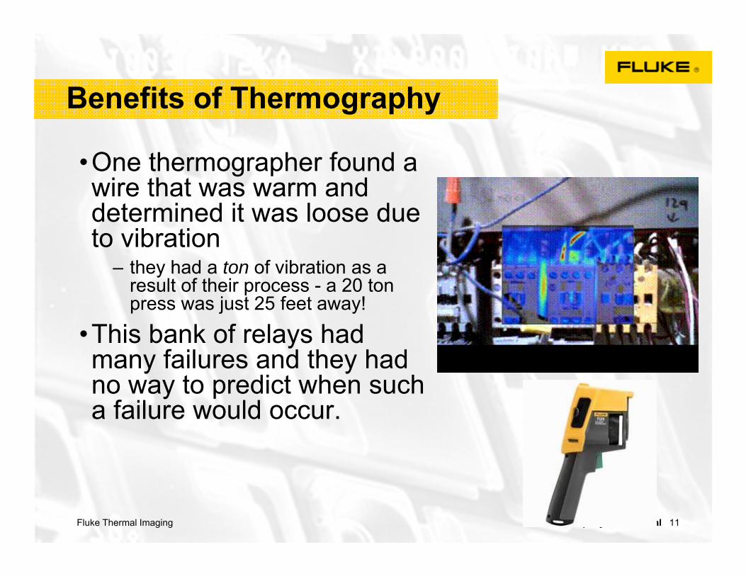
Benefits of Thermography
•One thermographer found a wire that was warm and determined it was loose due to vibration
– they had a ton of vibration as a result of their process - a 20 ton press was just 25 feet away!
•This bank of relays had many failures and they had no way to predict when such a failure would occur.

Fluke Thermal Imaging Company Confidential 12
Let’s see what we can do with an Imager…

Fluke Thermal Imaging Company Confidential 13
Thermal Imaging helps find/solve problems in electrical circuit
• Overloaded systems or excessive current
• Loose or corroded connections
• Component failures• Wiring mistakes• Under-specified components• Power quality problems like
phase unbalance, overload or harmonic distortion
• Insulation failures

Fluke Thermal Imaging Company Confidential 14
Thermal Imaging helps find/solveproblems in electric motor
• Over-heating due to:- reduced cooling airflow- under sized- electrical insulation
degradation in windings
• Bearing wear due to:- poor lubrication - miss alignment- excess belt tension
Fluke Thermal Imaging Company Confidential 15
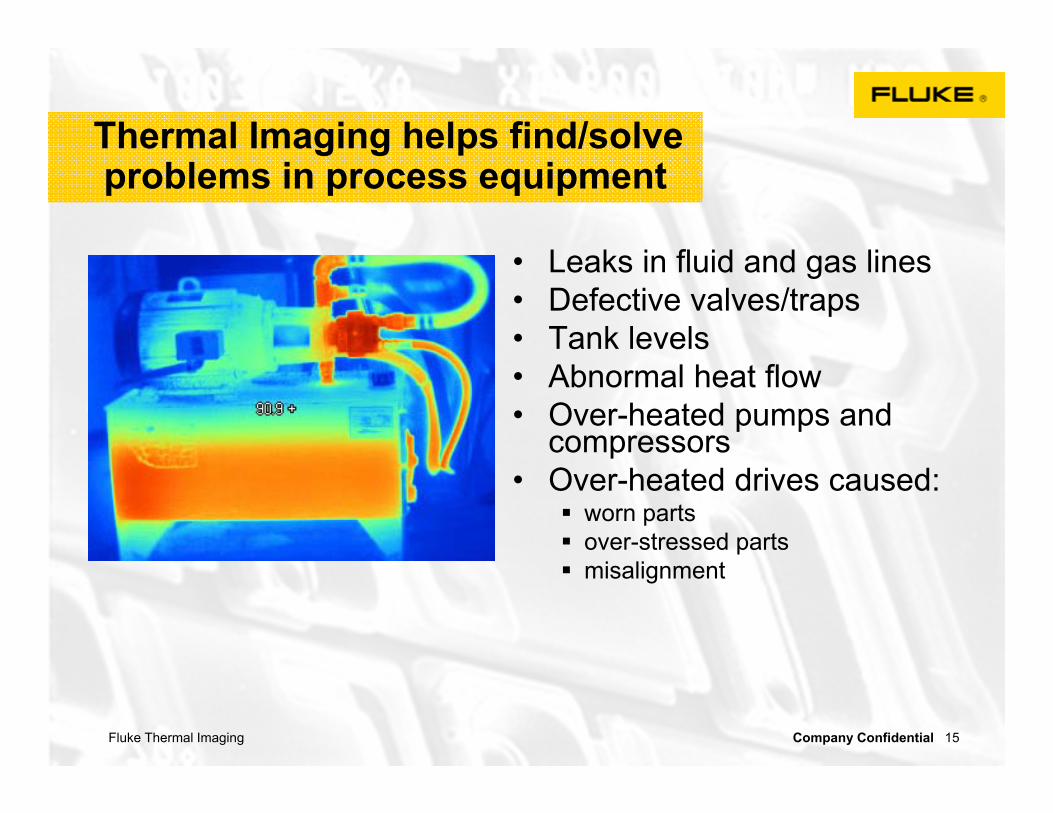
Thermal Imaging helps find/solveproblems in process equipment
• Leaks in fluid and gas lines• Defective valves/traps• Tank levels• Abnormal heat flow• Over-heated pumps and
compressors• Over-heated drives caused:
worn parts over-stressed parts misalignment

Fluke Thermal Imaging Company Confidential 16
Thermal Applications
Electrical
Motors
Process Control
Building Envelope and Roof
Transportation
Fluke Thermal Imaging Company Confidential 17
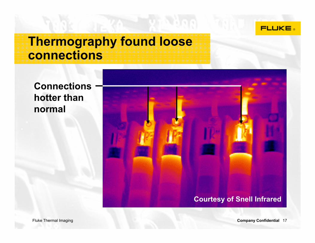
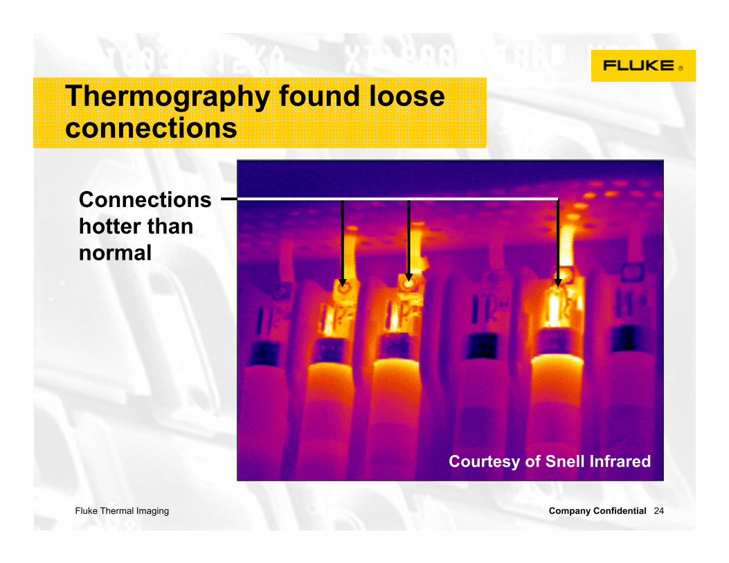
Connections hotter than normal
Courtesy of Snell Infrared
Thermography found loose connections
Fluke Thermal Imaging Company Confidential 18
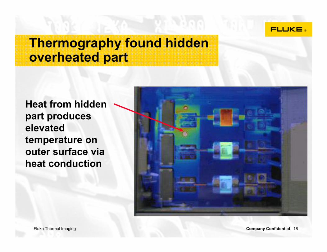
Heat from hidden part produces elevated temperature on outer surface via heat conduction
Thermography found hidden overheated part

Fluke Thermal Imaging Company Confidential 19
Far-right compressor is obviously off
Thermography works especially well with multiple units
Fluke Thermal Imaging Company Confidential 20
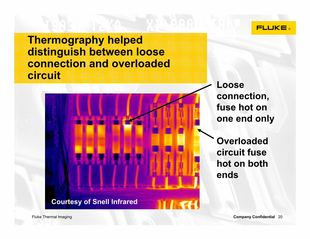
Overloaded circuit fuse hot on both ends
Loose connection, fuse hot on one end only
Courtesy of Snell Infrared
Thermography helped distinguish between loose connection and overloaded circuit

Fluke Thermal Imaging Company Confidential 21
Transformer problem easily identified from a distance
Thermography helped identify overheated pole transformer

Fluke Thermal Imaging Company Confidential 22
Hot v-belt stressed due to wear and/or misalignment
Thermography helped identify a worn belt

Fluke Thermal Imaging Company Confidential 23
Thermography helped identify tank fill levels
Fluke Thermal Imaging Company Confidential 24
Connections hotter than normal
Courtesy of Snell Infrared
Thermography found loose connections
Fluke Thermal Imaging Company Confidential 25
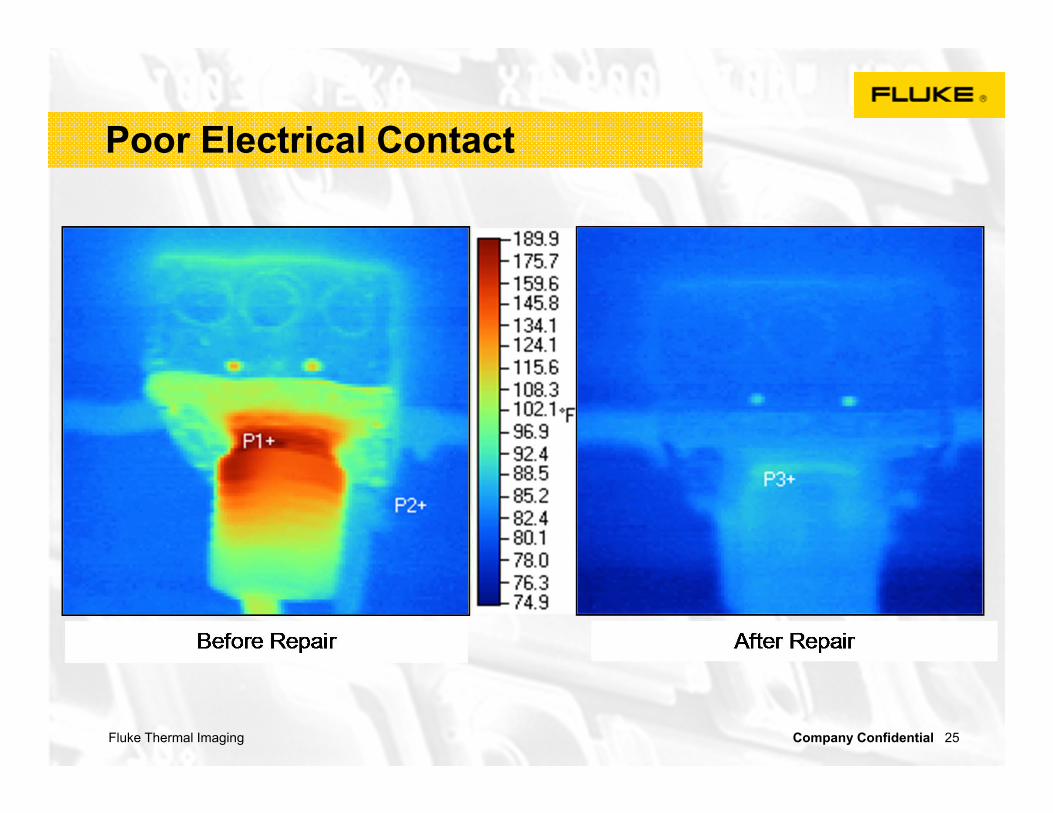
Poor Electrical Contact
Fluke Thermal Imaging Company Confidential 26
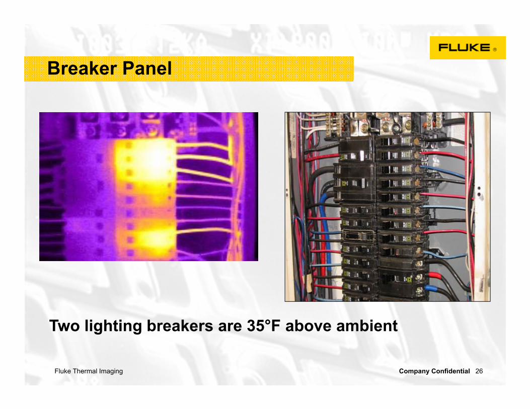
Breaker Panel
Two lighting breakers are 35°F above ambient
Fluke Thermal Imaging Company Confidential 27
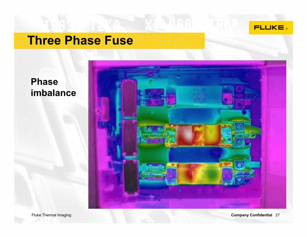
Phase imbalance
Three Phase Fuse

Fluke Thermal Imaging Company Confidential 28
Loose Fuse Socket
Extra resistance at one end of fuse socket

Fluke Thermal Imaging Company Confidential 29
Some cooling tubes appear to be plugged
Transformer Cooling

Fluke Thermal Imaging Company Confidential 30
Cooling Systems
Fluke Thermal Imaging Company Confidential 31
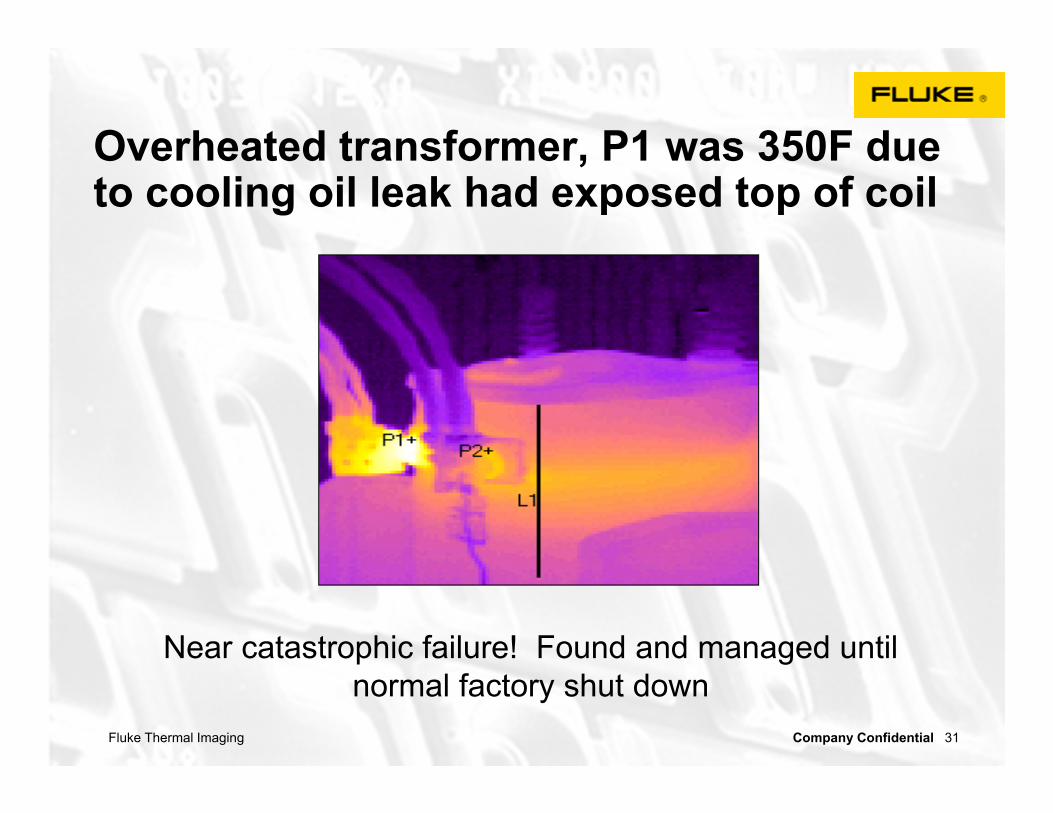
Overheated transformer, P1 was 350F due to cooling oil leak had exposed top of coil
Near catastrophic failure! Found and managed until normal factory shut down

Fluke Thermal Imaging Company Confidential 32
Motor control centers
Inspect lug connections and also look for subtle patterns that may be caused by internal contacts
or connections to the bus
Courtesy of Snell Infrared
Fluke Thermal Imaging Company Confidential 33
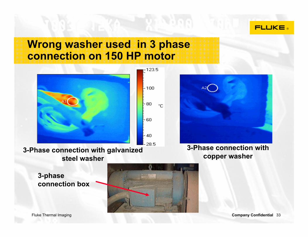
Wrong washer used in 3 phase connection on 150 HP motor
3-Phase connection with galvanized steel washer
3-Phase connection with copper washer
3-phase connection box

Fluke Thermal Imaging Company Confidential 34
Motors
Uneven heating in an electrical motor will reduce the life and efficiency of the motor if not properly addressed
For each 10ºC (18ºF) rise over maximum rated temperature, approximately ½ the life of a motor is lost due to insulation failure!

Fluke Thermal Imaging Company Confidential 35
Thermal Imaging helps find/solveproblems in electric motor
• Over-heating due to:- reduced cooling
airflow- under sized- electrical insulation
degradation in windings
• Bearing wear due to:- poor lubrication - miss alignment- excess belt tension
Fluke Thermal Imaging Company Confidential 36
This image cannot currently be displayed.
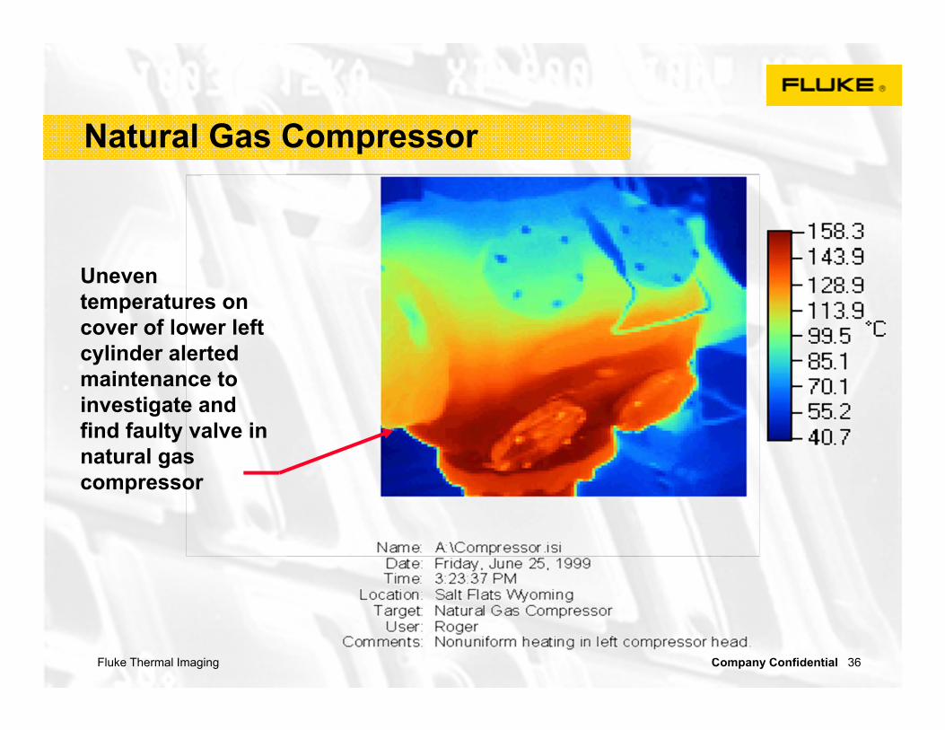
Uneven temperatures on cover of lower left cylinder alerted maintenance to investigate and find faulty valve in natural gas compressor
Natural Gas Compressor

Fluke Thermal Imaging Company Confidential 37
Small bearings
• No other method is as effective or fast for small bearings
• Small bearing failures can result in fire, mechanical stress, belt wear, and increased electrical loads
93.7°F
117.8°F
95
100
105
110
115
Fluke Thermal Imaging Company Confidential 38
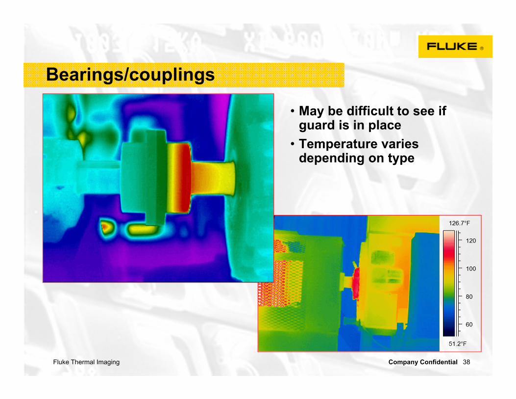
Bearings/couplings
• May be difficult to see if guard is in place
• Temperature varies depending on type
Fluke Thermal Imaging Company Confidential 39
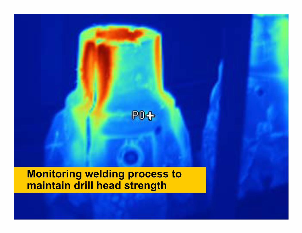
Monitoring welding process to maintain drill head strength

Fluke Thermal Imaging Company Confidential 40
Determine valve on/off and leakage
Steam Traps

Fluke Thermal Imaging Company Confidential 41
Steam Traps
Fluke Thermal Imaging Company Confidential 42
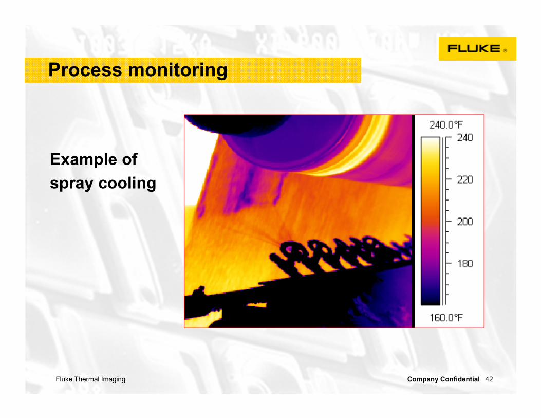
Process monitoring
Example of spray cooling

Fluke Thermal Imaging Company Confidential 43
How does it work?
•19,200 detectors or more can be fabricated into a two-dimensional array called a Focal Plane Array (FPA)
•Each individual detector measures the incoming radiation and converts this data to a thermo-gram, or visual image, which we use for detailed temperature analysis and documentation
Fluke Thermal Imaging Company Confidential 44
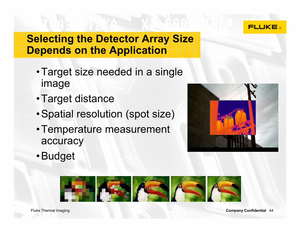
Selecting the Detector Array SizeDepends on the Application
•Target size needed in a single image
•Target distance •Spatial resolution (spot size)•Temperature measurement accuracy
•Budget

Fluke Thermal Imaging Company Confidential 45
Heat Energy
•Energy exists in many forms– Mechanical– Electrical– Chemical– Nuclear– Thermal (heat)
• It is energy that is absorbed or released as an object changes temperature
– always moves from warmer to colder areas
•A pail of water contains more heat energy than a cup and as a result will take longer to cool under equal conditions

Fluke Thermal Imaging Company Confidential 46
Heat Transfer
• Heat transfer can be:– Transient: temperature is constantly and significantly changing– Steady state: heat flow is constant with time

Fluke Thermal Imaging Company Confidential 47
Three Modes of Heat Transfer
• Radiation is the transmission of electromagnetic rays through space
– Each material that has a temperature above absolute zero (-460°F) emits infrared radiation,
• Conduction is direct heat flow through matter
– Fun fact: Notice how metal feels cold? It is not –that is only the metal taking energy away from your hand and we perceive this as “cold”!
• Convection is the transport of heat within a gas or liquid
– Cold air drops so A/C vents are high– Warm air rises so heating vents are on floor

Fluke Thermal Imaging Company Confidential 48
Conduction Examples
Heat is conducted away from a corroded and high resistance connection showing a temperature gradient along the fuse

Fluke Thermal Imaging Company Confidential 49
Experiment # 1
Examine the wire and notice one end is much hotter than the other; also note the difference in temperature between the insulation and the bare copper wire

Fluke Thermal Imaging Company Confidential 50
Convection mixing
Warm water discharge from Power Plant is mixed with cooler river water

Fluke Thermal Imaging Company Confidential 51
Be aware: wind can effect temperature
15 mph wind
85F 76F 72F
T = 13F
117F 95F 81F
No windT = 36FPhoto courtesy of Snell Infrared

Fluke Thermal Imaging Company Confidential 52
Wind Effects
• Wind can significantly reduce temperature of hot spot
• Rule of thumb– 10 mph can reduce T by up
to 1/2– 15 mph can reduce T by up
to 2/3
• Roof moisture inspection is very difficult in wind

Fluke Thermal Imaging Company Confidential 53
Combined Conduction and Convection Examples
•Heat from outside is conducted through siding, convected inside empty wall cavity, conducted through inside wall board and convected into air conditioned room

Fluke Thermal Imaging Company Confidential 54
Thermal Capacitance
• The amount of energy an object needs to absorb or release in order to change temperature
– Water heats and cools slowly because of its high heat capacity
– Air heats and cools rapidly because of its low heat capacity
• How quickly this change take place depends on thermal capacitance and thermal conductivity – not time.
• Which has the highest thermal capacitance?
– Copper– Steel– Brick– Wood– Water

Fluke Thermal Imaging Company Confidential 55
Understanding Thermography
• The camera sensors detect infrared radiation from the surface
• Only the emitted radiation tells us about surface temperature.
• Different surfaces absorb and emit radiation differently – this is called “emissivity”
• Operator must tell the camera the emissivity value and background temperature (reflective) to obtain accurate results

Fluke Thermal Imaging Company Confidential 56
1st Law of Thermodynamics
• Radiation can be transmitted through a surface
– Our IR camera lens, for example– Does not change the temperature of the surface!
• Radiation can be reflected off a surface– Remember our glass window example?– Does not change the temperature of the surface!
• Radiation can be absorbed and re-emitted– Amount of energy absorbed = re-emitted– This is what we measure with our IR camera!
• Reflected + Absorbed + Transmitted = 1– Known as the RAT law– Can also say R+E+T=1 Reflected
Transmitted
Absorbed
Re-emitted
Fluke Thermal Imaging Company Confidential 57
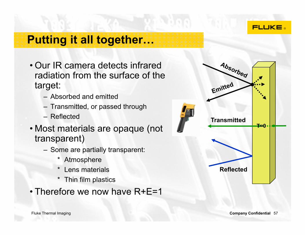
Putting it all together…
• Our IR camera detects infrared radiation from the surface of the target:
– Absorbed and emitted– Transmitted, or passed through– Reflected
• Most materials are opaque (not transparent)
– Some are partially transparent:* Atmosphere * Lens materials* Thin film plastics
• Therefore we now have R+E=1
Reflected
TransmittedT=0
Fluke Thermal Imaging Company Confidential 58
Emissivity (ε )
•Pronunciation: "Em`is*siv"i*ty ”•Definition: scientific measurement of the ability for absorbed heat energy to radiate (leave) an object as compared to a black body at the same temperature
– a true black body radiates 100% of its absorbed energy (nothing is reflected or transmitted) so the ε = 1
– A perfect reflector would have an ε = 0
•Materials that are not black bodies only radiate a fraction of the radiation as a black body at the same temperature and wave length so the ε is <1

Fluke Thermal Imaging Company Confidential 59
This is a Key Relationship
•R+E=1– Emitters don’t make good
reflectors– Reflectors don’t make good
emitters
•Difficult to make accurate measurements on highly reflective surfaces
– If emissivity is below 0.6 measurement is unreliable
Fluke Thermal Imaging Company Confidential 60
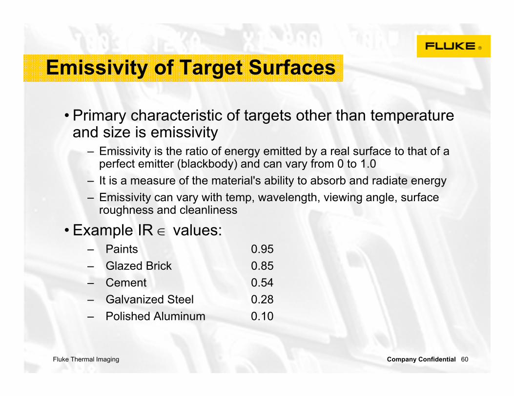
Emissivity of Target Surfaces
• Primary characteristic of targets other than temperature and size is emissivity
– Emissivity is the ratio of energy emitted by a real surface to that of a perfect emitter (blackbody) and can vary from 0 to 1.0
– It is a measure of the material's ability to absorb and radiate energy– Emissivity can vary with temp, wavelength, viewing angle, surface
roughness and cleanliness
• Example IR values:– Paints 0.95– Glazed Brick 0.85 – Cement 0.54– Galvanized Steel 0.28 – Polished Aluminum 0.10

Fluke Thermal Imaging Company Confidential 61
Simple guidelines
• All objects of organic origin have emissivity of approx. 0.95
– Soil, lime, stone, paper, textile
– Non-metallic paint, plastic, rubber
– Oil, grease, dust
• Apply tape or paint to increase emissivity
• Whenever possible, increase emissivity!
Fluke Thermal Imaging Company Confidential 62
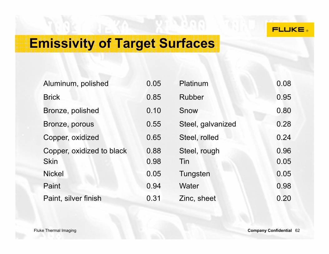
Emissivity of Target Surfaces
Aluminum, polished 0.05 Platinum 0.08
Brick 0.85 Rubber 0.95
Bronze, polished 0.10 Snow 0.80
Bronze, porous 0.55 Steel, galvanized 0.28
Copper, oxidized 0.65 Steel, rolled 0.24
Copper, oxidized to black 0.88 Steel, rough 0.96Skin 0.98 Tin 0.05Nickel 0.05 Tungsten 0.05Paint 0.94 Water 0.98Paint, silver finish 0.31 Zinc, sheet 0.20

Fluke Thermal Imaging Company Confidential 63
What is IR-Fusion® ?
• IR-Fusion® only is available on Fluke Thermal Imagers
– Be aware of imitations!
• IR-Fusion® links the Thermal Image with the Visual Image
– Easier to understand what you are looking at* See the context* Read any markers/labels/text* No laser pointer needed
– Easier to report findings to others* No need to also take a picture with a
normal camera– Helps you focus the Thermal Imager better
* The Thermal Imager is focused correctly when the Thermal and Visual images are completely aligned

Fluke Thermal Imaging Company Confidential 64
IR Fusion® view modes
•Traditional full IR– full display is 100% infrared
•Full visible – full display is 100% visible
•Blended full – full display is IR blended with
visible
Fluke Thermal Imaging Company Confidential 65
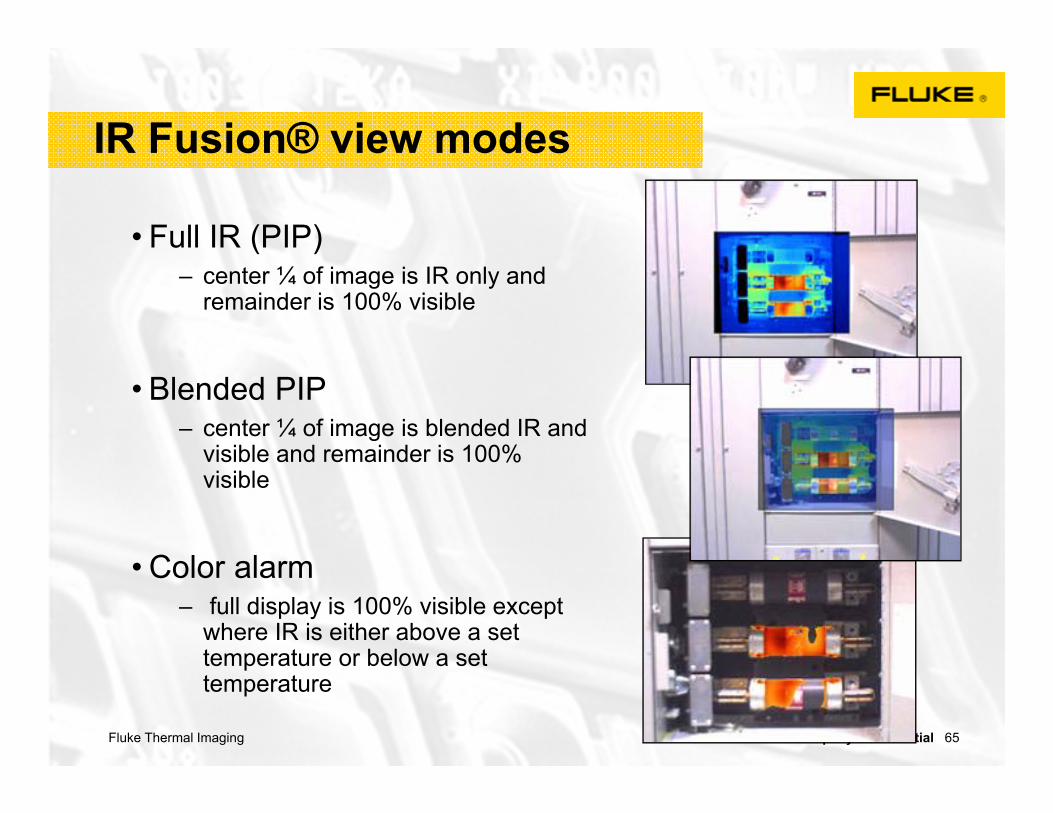
IR Fusion® view modes
• Full IR (PIP) – center ¼ of image is IR only and
remainder is 100% visible
• Blended PIP – center ¼ of image is blended IR and
visible and remainder is 100% visible
• Color alarm– full display is 100% visible except
where IR is either above a set temperature or below a set temperature

Fluke Thermal Imaging Company Confidential 66
Hawk-IR - Sightglasses
• Also called– Infrared Sightglass (Windows) – Infrared Viewing Ports– Infrared Viewing Panes
• WHAT is their function?– Allow safer inspection of live equipment– Provide a barrier to protect against electrocution– Provide a degree of protection against electric arcs
Fluke Thermal Imaging Company Confidential 67
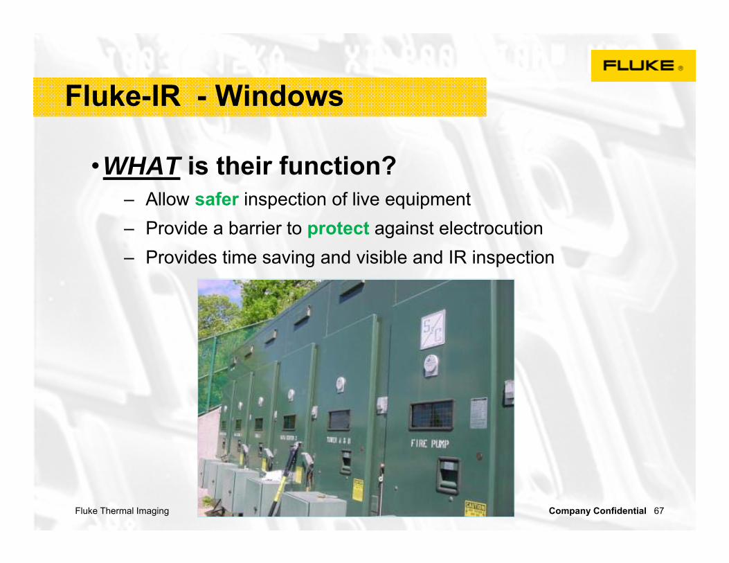
Fluke-IR - Windows
•WHAT is their function?– Allow safer inspection of live equipment– Provide a barrier to protect against electrocution– Provides time saving and visible and IR inspection

Fluke Thermal Imaging Company Confidential 68
Hawk-IR - Sightglasses
• WHERE can you use them?– LV, MV, HV Switchgear– MV Starters– MV Motors– Transformers– Bus-Duct

Fluke Thermal Imaging Company Confidential 69
Hawk-IR - Sightglasses
C-Range Quadraband™ Sightglass50kA Arc-Resistant Design
Multispectral optic (IR & UV)
Impervious to moisture
Fusion compatible
AutoGround design
Visually transparent

Fluke Thermal Imaging Company Confidential 70
Fluke Ti series
For everyday troubleshooting and maintenance

Fluke Thermal Imaging Company Confidential 71
Ti Imager features

Fluke Thermal Imaging Company Confidential 72
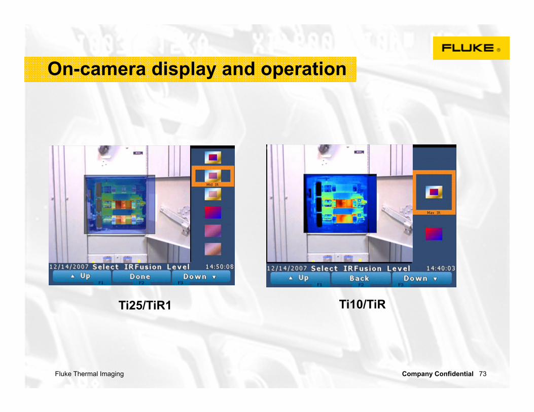
IR-Fusion ® Imager viewing modes
Max IR(traditional Thermal Imaging) Mid IR Min IR
PIP Max IR PIP Mid IR PIP Min IRTi25 OnlyTi25 and Ti10
Fluke Thermal Imaging Company Confidential 73
On-camera display and operation
Ti25/TiR1 Ti10/TiR

Fluke Thermal Imaging Company Confidential 74
Qualitative vs. Quantitative
• Qualitative (most common)– Utilize the thermal differences
(∆T) to locate anomalies– Temperature differences
between like components under similar load conditions, or differences between components and ambient temperature, are usually sufficient to indicate most abnormalities
Action Navy¹ ² NMAC³Advisory
IntermediateSerious
Immediate
10-24 °C25-39 °C40-69 °C70 °C+
1-3 °C4-15 °C
N/A16 °C+
0.5-8 °C9-28 °C29-56 °C56 °C+
¹ Rise over (unspecified) reference. Normal operation load² Load at 10-40%. Three categories only.³ Rise over (unspecified) reference.: International Electrical Testing AssociationNMAC: Nuclear

Fluke Thermal Imaging Company Confidential 75
Qualitative vs. Quantitative
• Quantitative– Precise temperature
measurement– Caution: slight differences in
emissivity, background and other conditions will distort findings
– Can also be effected by spot size, or IFOVmeas

Fluke Thermal Imaging Company Confidential 76
Measurement Accuracy
• Field of View (FOV) is total target area seen by imager
• Instantaneous Field of View (IFOV) is the smallest area which can be seen by the imager (Spatial Resolution or spot size)
• Measurement Instantaneous Field of View (IFOVmeas) is the smallest area an imager can measure and is usually 2-3 times smaller than IFOV
– Determined by number of system properties, not just the pixel resolution
115.9°
120.2°

Fluke Thermal Imaging Company Confidential 77
FOV, IFOV, IFOVmeas
Fluke IR

Fluke Thermal Imaging Company Confidential 78
Level and Span
• Span: Size of the thermal window
– 30°F in both images
• Level: Height of the thermal window
– 95°F in top image– 66°F in bottom image
• Saturation colors will be displayed when the temperature in the field of view is above or below the thermal window defined on the camera
Fluke Thermal Imaging Company Confidential 79
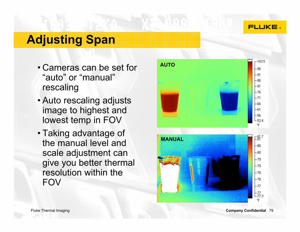
Adjusting Span
• Cameras can be set for “auto” or “manual” rescaling
• Auto rescaling adjusts image to highest and lowest temp in FOV
• Taking advantage of the manual level and scale adjustment can give you better thermal resolution within the FOV
Level = 80.55F
AUTO
MANUAL

Fluke Thermal Imaging Company Confidential 80
Building - “Level & Span”

Fluke Thermal Imaging Company Confidential 81
Palette Selection
Iron Bow
Hot MetalBlue-Red
Grey Scale
Fluke Thermal Imaging Company Confidential 82
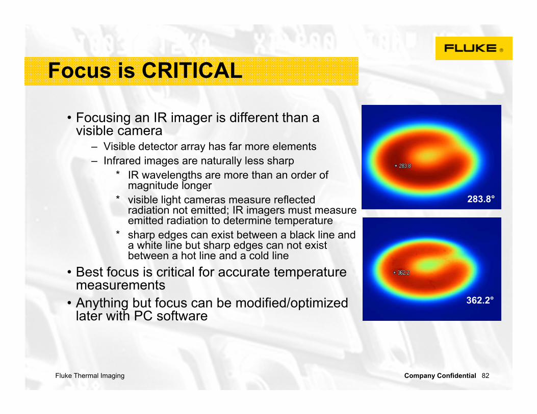
Focus is CRITICAL
• Focusing an IR imager is different than a visible camera
– Visible detector array has far more elements– Infrared images are naturally less sharp
* IR wavelengths are more than an order of magnitude longer
* visible light cameras measure reflected radiation not emitted; IR imagers must measure emitted radiation to determine temperature
* sharp edges can exist between a black line and a white line but sharp edges can not exist between a hot line and a cold line
• Best focus is critical for accurate temperature measurements
• Anything but focus can be modified/optimized later with PC software
283.8°
362.2°

Fluke Thermal Imaging Company Confidential 83
Best Focus Practices
•Look for edges•Use IR-Fusion•Hold imager still •Some people find best results with the gray scale palette

Fluke Thermal Imaging Company Confidential 84
Checking your imager calibration
• Routinely check basic calibration before each scan.
• Here are a few simple test you can perform
– Check the tear duct of a work partner (recommend the same person)
– Check an ice bath to verify camera performance at 0º C
– Check boiling water to verify camera performance at 100º C
– Acquire a blackbody reference in one of your common temp ranges

Fluke Thermal Imaging Company Confidential 85
Large widescreen display
•3.5 inch
•640 x 480 pixels resolution
•Crystal clear images
Fluke Thermal Imaging Company Confidential 86
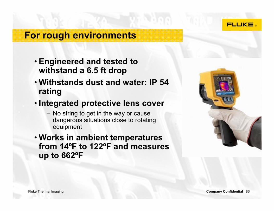
For rough environments
• Engineered and tested to withstand a 6.5 ft drop
• Withstands dust and water: IP 54 rating
• Integrated protective lens cover– No string to get in the way or cause
dangerous situations close to rotating equipment
• Works in ambient temperatures from 14ºF to 122ºF and measures up to 662ºF
Fluke Thermal Imaging Company Confidential 87
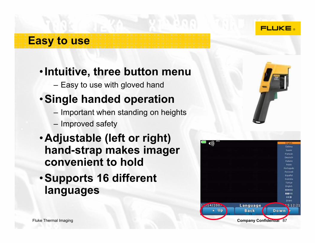
Easy to use
• Intuitive, three button menu – Easy to use with gloved hand
•Single handed operation– Important when standing on heights– Improved safety
•Adjustable (left or right) hand-strap makes imager convenient to hold
•Supports 16 different languages
Fluke Thermal Imaging Company Confidential 88
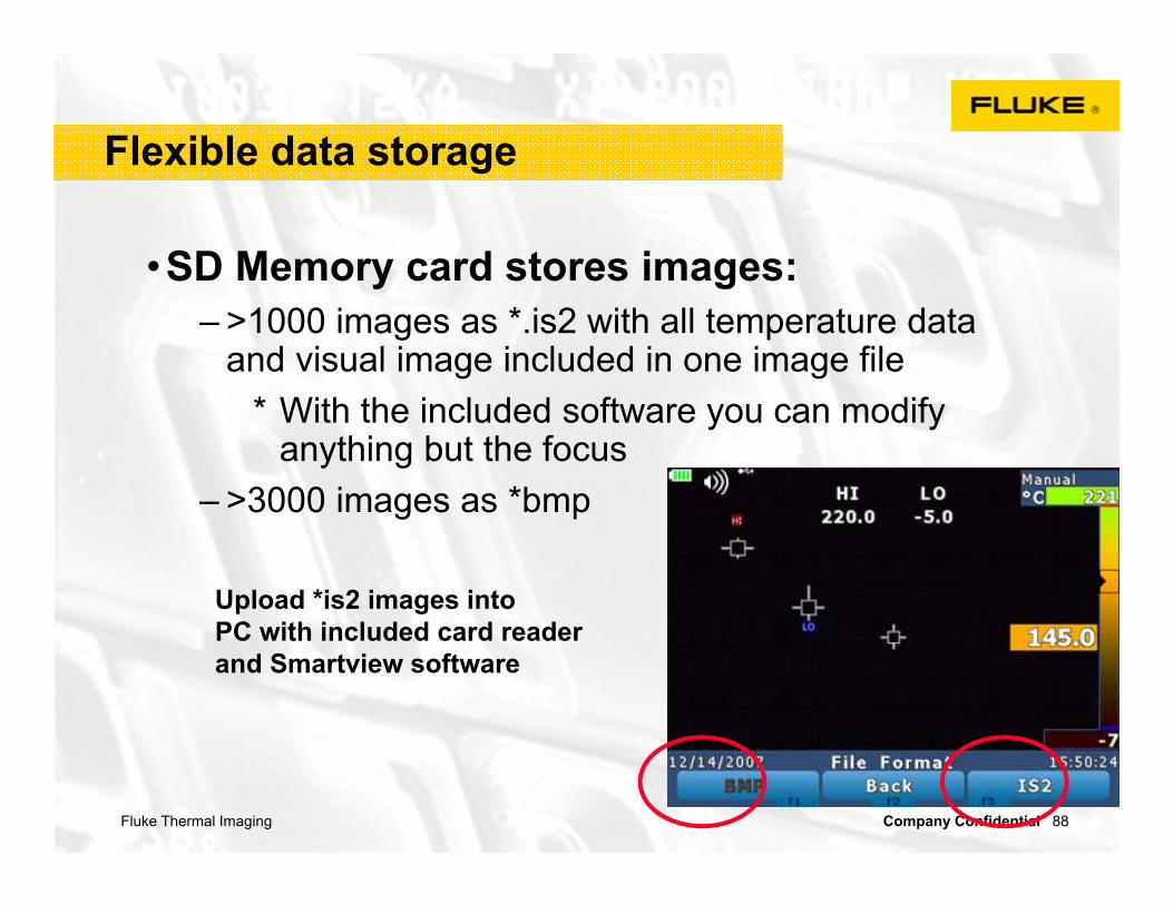
Flexible data storage
•SD Memory card stores images:– >1000 images as *.is2 with all temperature data
and visual image included in one image file* With the included software you can modify
anything but the focus– >3000 images as *bmp
Upload *is2 images into PC with included card reader and Smartview software

Fluke Thermal Imaging Company Confidential 89
Voice annotation (Ti25/TiR1 only)
•Record and save commentary with stored images
– Up to 1 minute with every image
– No need to write down comments
•Playback (review) on Imager or with the software
Fluke Thermal Imaging Company Confidential 90
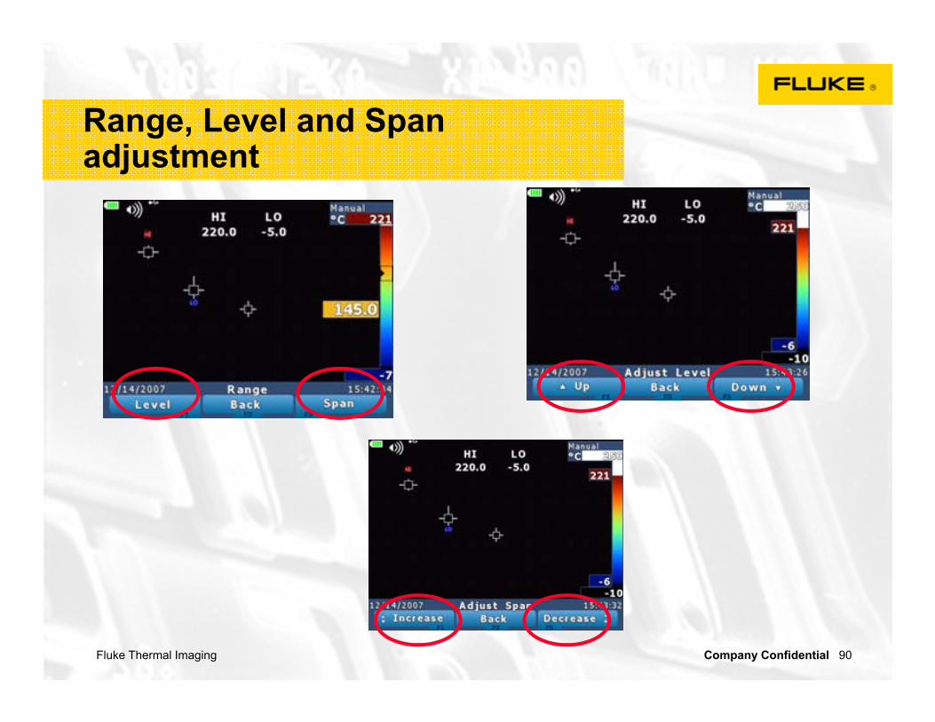
Range, Level and Span adjustment

Fluke Thermal Imaging Company Confidential 91
Color Palettes
•Choose from 6 different palettes

Fluke Thermal Imaging Company Confidential 92
Imager settings

Fluke Thermal Imaging Company Confidential 93
On-board analysis
•Spot temperature indicators– Center point– High and low marker (Ti25/TiR1 only)
* Max and min temperature on image
•Emissivity correction – Select from table or enter manually

Fluke Thermal Imaging Company Confidential 94
One Complete Package
• Included with every Ti: – Rugged hard case– Portable soft case– Adjustable handstrap– 2 GB SD memory card– SD memory card reader– Internal rechargeable battery– AC charger/power supply– Smartview analysis and
reportingsoftware

Fluke Thermal Imaging Company Confidential 95
Selecting the right Imager
•There are 12 Fluke Thermal Imagers to choose from
•Go to the Selector Tool on www.Fluke.com to select the Fluke Imager that best fits your needs

Fluke Thermal Imaging Company Confidential 96
The reality
You can do this1. Fluke Thermal Imagers are easy to use, point/focus/capture2. They will make you more effective3. This means more in-sourcing instead of outsourcing
You WILL find problems1. You will solve problems faster2. You will save money
IF….1. Initiate a PdM program at some level2. Create a “Trophy Board”3. Pay attention to your “cost avoidance”
Your investment is minimal, the payback( ROI) potential is huge
You can verify that the problem has really been solved!

Fluke Thermal Imaging Company Confidential 97
Fluke Thermal Imaging
THANKS FOR COMING!
Marcus Thomas NW Territory Sales Engineer