PRACTICAL METHODOLOGY - Oregon State University
29
J u n e 2 0 0 4 R e s e a r c h C o n t r i b u t i o n 4 5 Forest Research Laboratory PRACTICAL METHODOLOGY FOR OPERATIONAL LAYOUT OF COMMERCIAL SKYLINE THINNING SYSTEMS by Jennie L Cornell Loren Kellogg
Transcript of PRACTICAL METHODOLOGY - Oregon State University

J u n e 2 0 0 4
R e s e a r c h C o n t r i b u t i o n 4 5
Fo re s t Re s ea rch L abo ra to r y
PRACTICAL METHODOLOGY
FOR OPERATIONAL LAYOUT
OF COMMERCIAL SKYLINE
THINNING SYSTEMS
by
Jennie L Cornell
Loren Kellogg

Editing, word processing, design, and layout by Forestry Communications Group.
The Forest Research Laboratory of Oregon State University, established by the Oregon Legislature, conducts research leading to sustainable forest yields, innovative and efficient use of forest prod-ucts, and responsible stewardship of Oregon's forest resources. Its scientists conduct this research in labo-ratories and forests administered by the University and cooperating agencies and industries throughout Oregon. Research results are made available to potential users through the University’s educational programs and through Laboratory publications such as this, which are directed as appropriate to forest landowners and managers, manufacturers and us-ers of forest products, leaders of government and industry, the scientific community, the conservation community, and the general public.
THE AUTHORS
At the time this paper was written, Jennie L Cor-nell was Graduate Research Assistant, Department of Forest Engineering, Oregon State University, Corvallis. Loren Kellogg is Professor, Department of Forest Engineering, Oregon State University, Corvallis.
DISCLAIMER
Reference herein to any specific commercial prod-uct, process, or service by trade name, trademark, manufacturer, or otherwise, does not necessarily constitute or imply its endorsement or recommen-dation by Oregon State University. The views and opinions of authors expressed herein do not necessarily reflect those of Oregon State University, and shall not be used for advertising or product endorsement.
TO ORDER COPIES
Copies of this and other Forest Research Laboratory publications are available from
Forestry Communications GroupOregon State University256 Peavy HallCorvallis, Oregon 97331-5704Phone: (541) 737-4271FAX: (541) 737-4077Email: [email protected] site: http://www.cof.orst.edu/cof/pub/home/
Please indicate author(s), title, and publication number if known.
DEDICATION
Jerome ‘Jerry’ SedlakOctober 1952 – September 2003
Jerry Sedlak was a 1978 OSU Forest Engineer-ing Masters Alum; served on the FE Department Advisory Committee; and assisted regularly with guest lectures, field trips, research efforts, and job opportunities for FE students. He was President of Emerald Valley Thinning, a member of the As-sociated Oregon Loggers, the Society of American Foresters, and actively involved in the Springfield, Oregon community. Jerry is remembered as an innovative and tenacious logger who coupled his professional engineering background with a deep respect for forestry.

Fores t Resea rch Labora to r y
Research Contribution 45
June 2004
PRACTICAL METHODOLOGY FOR
OPERATIONAL LAYOUT OF COMMERCIAL
SKYLINE THINNING SYSTEMS
by
Jennie L Cornell
Loren Kellogg

ABSTRACT
Cornell, JL, and L Kellogg. 2004. Practical Methodology for Op-erational Layout of Commercial Skyline Thinning Systems. Research Contribution 45, Forest Research Laboratory, Oregon State Uni-versity, Corvallis.
On-the-ground harvest unit layout, especially in skyline-thinning operations, is critical to meeting multiple resource objectives of the land manager and maintaining the economic viability of the timber harvesting operator. This phase of an operation can optimize the layout and harvesting of a sale or unit. Detailed layout by a knowl-edgeable professional can help to identify areas in the sale or unit that may be operationally or economically unfeasible to thin.
This publication is an overview of practical methodology aspects for the layout of skyline thinning operations. The information presented is drawn largely from the personal experiences of the authors, the individuals cited, and publications from research at Oregon State University. The publication provides a general outline of the components of the overall planning process that results in the implementation of skyline thinning operations on the ground.
Keywords: Commercial thinning, forest harvesting, forest engineer-ing, harvest planning, logging, silviculture
ABBREVIATIONS, CONVERSIONS, AND SYMBOLS
1 acre (ac) = 0.404 ha
1 foot (ft) = 0.305 m
1 inch (in. or ") = 2.54 centimeters (cm)
1 mile (mi) = 1.61 kilometers (km)
° = degrees

CONTENTS
ABSTRACT ........................................................... 2
LIST OF FIGURES ................................................... 4
INTRODUCTION ..................................................... 5
PLANNING PROCESS ............................................... 5
FIELD LAYOUT ...................................................... 7 IMPORTANCE .........................................................7 KNOWLEDGE AND EXPERIENCE BASE .............................7 UNIT LAYOUT .......................................................8
TOOLS, TECHNIQUES, AND PROCEDURES .................... 21 TOOLS ..............................................................21 TECHNIQUES .......................................................21 PROCEDURES .......................................................22
LITERATURE CITED ............................................... 25

LIST OF FIGURES
Figure 1. The planning process ................................................................................................................ 5
Figure 2. The ground layout process ........................................................................................................ 8
Figure 3. Typical multispan yarding configuration with a standing skyline ................................................. 9
Figure 4. Examples of guyline configurations for various yarders ............................................................. 10
Figure 5. Guideline for determining guyline angles and slope distance to anchors to stay within a 50° maximum angle ......................................................................................... 10
Figure 6. Operational considerations for corridor layout ......................................................................... 12
Figure 7. Reconnaissance map and field notes ....................................................................................... 12
Figure 8. Designed landing for a Koller 501 yarder ................................................................................. 13
Figure 9. A suitable landing, with yarder and loader ............................................................................... 13
Figure 10. Landing operations diagram for a Koller 300 yarder and rubber-tired skidder ......................... 14
Figure 11. Sidehill corridor ..................................................................................................................... 14
Figure 12. A long straight corridor ......................................................................................................... 15
Figure 13. Parallel and fan-shaped patterns of corridors in a completed skyline thinning unit .......................... 15
Figure 14. Unit layout map with flagged skyline corridors and field notes ............................................... 16
Figure 15. Double-tree intermediate support .......................................................................................... 17
Figure 16. Single-tree intermediate support: (a) sideblock, (b) centerblock ............................................... 17
Figure 17. Guidelines for placement of support trees, lift trees and anchors ............................................ 18
Figure 18. Single-tree intermediate support (side-block rigging) with (a) one guyline and (b) two guylines ...................................................................................................... 19
Figure 19. General guyline configuration for a single-tree intermediate support (center-block rigging) ................................................................................................................ 19
Figure 20. Skyline positioning limits for a tail/lift tree .............................................................................. 19
Figure 21. Completed corridor layout map with field notes and instructions ........................................... 20
Figure 22. Procedure for prolongation of a straight line for corridor location ........................................... 21
Figure 23. Hand compass method to offset around obstacles in corridor ................................................ 22
Figure 24. Staff compass method to offset around obstacles in corridor .................................................. 22
Figure 25. Layout of parallel skyline corridors ......................................................................................... 23
Figure 26. Layout of a fan-shaped corridor pattern ................................................................................. 23
Figure 27. Application of a corrected bearing ......................................................................................... 24

5
INTRODUCTION
With the current trends in reduced harvests from older forests on public lands in the Pacific Northwest, the focus is shifting towards commercial harvesting of younger timber on both public and private lands to satisfy the demand for wood and fiber products. An
increasing proportion of that harvest is from commercial thinning of young stands (McNeel and Dodd 1996), although commercial thinning has declined on private industrial lands in recent years.
This publication outlines the operational aspects of plan-ning, laying out, and successfully implementing com-mercial skyline thinning in mountainous terrain. The main focus is on practical layout procedures. Most of the information is derived from years of practical experience by successful operators, technical reports, and papers from research and continuing education events conducted at the Department of Forest Engineering at Oregon State University. Kellogg et al. (2002) provide a broad overview of timber harvesting systems.
PLANNING PROCESS
The planning process (Figure 1) begins at the overall stra-tegic level (Step 1). At this level, the land manager makes decisions for landscape-level planning on the basis of stand inventory structure, projected prices and market demands for different products, and environmental constraints. On private land, long-range timber harvesting schedules are planned for extended periods, usually through an entire rotation age. The manager considers a variety of factors to determine harvest schedules and production levels, such as combining one or more commercial thinnings with a final harvest. The combination and timing of harvesting techniques and silvicultural treatments are based on the desired outcomes and objectives of the land manager—for example, enhancement of wildlife habitat or a long-run
(1)Strategic Planning
Landscape-level Planning • Long-range: minimum one rotation • General land management objectives: long-run sustained yield, nondeclining even-flow, etc.
(2)Tactical Planning
Basin-Area Plans for Harvests, Roads, etc. • Mid-range: 5- to 10-yr planning period • Harvest levels and broad silvicultural prescriptions • Refined transportation plan and schedule
(3)Annual Planning
Generalized Unit Planning • Immediate time frame: within the fiscal year • Allocation of resources to implement the harvest goals and tactics outlined in the Tactical Planning phase
(4)Operational Unit Planning
Specific Unit Planning • Layout of unit boundaries • Road layout and construction • Cruising for volume/value • Specific silvicultural prescriptions • General harvest system planning • Consideration of environmental and other operational constraints
(5)Implementation
On-the-ground Layout
Objectives met?
• Selection of harvesting system equipment and procedures• Location and design of landings• Flagging skyline corridors• Location of problem areas and special needs• Organizing and coordinating operations to facilitate the overall safe and efficient harvesting of the unit
Figure 1. The planning process.

6
sustained yield for a given harvest volume. This concept in overall long-range planning ap-plies to all types of land managers; however, the specific approach varies from the family forest owner with as few as 10 ac up to large industrial landowners with millions of acres, public lands managed by local, state and federal agencies, and tribal holdings.
Step 2 is outlining a tactical plan. This plan focuses on a shorter time frame, such as 5 or 10 yr. The plan focuses on generating specific target harvest volumes from the landscape, as defined in the strategic plan; developing an overall transportation plan to address current and future needs; prescribing harvesting and silvicultural systems; and meeting environmental constraints and wildlife habitat needs.
Step 3 is annual (i.e., project-level) planning. A harvest goal is set, based on the tactical plan, and the annual planning process allocates resources to accomplish the desired outcomes. This includes budgeting to ensure adequate resources are available to meet the overall plan objectives. On Federal land, project-level planning differs and is referred to as a “Logging Feasibility Report” (personal communication, Rick Toupin, Forest Engineering Specialist, USDA Forest Service Region 6, Portland, Oregon).
The last two steps are on-the-ground application of the general objectives across the landscape with specific unit plans and layout. The operational planning (Step 4) is specific and defines harvest unit boundaries and volumes; silvicultural prescriptions; transportation systems; general harvest systems, such as ground-based or cable-based operations; and the constraints and tim-ing of the harvest operation. This is where the “how-to” is decided for implementing a harvest system design to accomplish forest management objectives. This step is largely completed by the land manager, the operations forester, or both.
This publication focuses on Step 5, the final step: on-the-ground layout. This step is often carried out by the logging contractor in consultation with the land manager.
The field layout of a skyline thinning unit is completed 1 wk to 3 mo before harvesting be-gins. Public agencies and a few private land managers typically complete the layout before the award of a contract. The specifications for appropriate equipment are used in designing the unit based on what appears to be the best logging system match for specific terrain and stand conditions. Logistical and operational feasibility problems may occur during logging, however, because each logging contractor can have different equipment and crew capabilities. Contract loggers often find it difficult and time-consuming to examine a commercial thinning sale when preparing a bid. Consequently, some problems may arise because of equipment limita-tions. Also, on-the-ground layout can lead to some areas of the operational harvest unit plan or timber sale being deleted because physical or economic limitations would make thinning infeasible. In this publication, for the most efficient process, we assume that the contractor is responsible for completing the final field layout in accordance with land manager objectives and constraints.

7
FIELD LAYOUT
IMPORTANCE
In planning on-the-ground implementation of operational plans, there are several factors to consider and a distinct process to follow to optimize the effectiveness of the layout activities and the harvesting system. The cost of harvest unit planning and layout is nominal compared with the gain in benefits from having a detailed, well-thought-out and well-executed plan. The increased efficiency and productivity of felling and of overall harvesting operations, including yarding and log hauling, far outweigh the time and money invested in a good operational plan and ground layout (Kellogg et al. 1998).
Many factors affect the investment in the harvest unit layout and plan. Those factors include experience of the layout person, availability of accurate topographic maps, steepness of the terrain, variability of the topography, drainage density, size and stocking distribution of the timber, density and species of the understory vegetation, maximum and average yarding dis-tances, accessibility for equipment and people, weather conditions, and environmental and contract constraints. These factors should be considered when scheduling the layout work in order to allocate sufficient time for the layout person to complete a comprehensive and high-quality plan.
KNOWLEDGE AND EXPERIENCE BASE
Some operators hire layout persons on a contract basis. Others use personnel within their own organization or do the work themselves. Whether the layout person is a contractor, a company employee, or an owner and operator, the requirements for a successful layout plan are the same.
The layout person needs to be familiar, in particular, with the harvest system that is to be used and how it will meet the overall management and harvesting objectives for the unit. The yarder and skyline carriage capabilities and characteristics determine landing location and size, landing frequency, maximum yarding distances, lateral yarding limits, maximum payloads, and acceptable skyline rigging configurations. The equipment and layout required to cable-thin a young-growth plantation can be quite different from the equipment that was used to harvest the unit the first time, especially if it was a long-span setting yarding large timber in a clearcut.
The layout person must have expertise in applying different harvesting system configurations on the ground and know the minimum anchor, support, and lift tree requirements for a harvest system. Skills in map reading, drawing layout plans, trigonometry, and basic surveying are also required. Communications skills are invaluable when relating the completed layout plan to the landowner, the operator, and the timber-falling and yarding crews.

8
UNIT LAYOUT The general ground layout process is outlined in Figure 2. The impor-tant factors and steps in the process are discussed below.
INFORMATION GATHERING: EQUIPMENT SELECTION AND OPERATIONAL CONSIDERATIONS
The first step is to determine the appropriate equipment for the given operational unit. Factors to consider include availability of equipment in the region, timing of availability, operating cost, and, more impor-tantly, cost per unit of production (e.g., $/ton). The availability of qualified contractors with suitable equipment is a major component of this consideration. Other useful information to gather includes topographic maps, timber cruise data, road maps with haul roads and routes, preliminary logging plan maps from the landowner, and contract requirements.
Cable systems for skyline harvesting include three main categories: standing skyline, live skyline, and running skyline. Manual or mechani-cal slackpulling and non-slackpulling carriages can be used with these systems. Yarders are usually of two types: swing boom or nonswing boom. In cable thinning, a standing skyline configuration (single span or multispan) (Figure 3) with a slackpulling carriage typically is used. Both types of yarders have been used successfully with this skyline and carriage combination. Live-skyline and running-skyline systems increase potential for residual stand damage along skyline corridors and are generally not preferred for thinning applications. Also, these systems are not commonly used with intermediate supports, and intermediate supports are often used in skyline thinning.
The type of equipment used for yarding affects the number of lift trees and the minimum tree sizes and rigging configurations needed for anchors, support trees, lift trees, and tailholds for the harvesting system. Some basic guidelines can be used in the layout process to en-sure operational feasibility. Examples of yarder guyline configurations and anchoring zones for selected yarders are illustrated in Figure 4.
Guidelines for maximum vertical line angles are illustrated in Figure 5 (Pyles 1991). Guidelines for anchor size and minimum rigged tree size are given in Tables 1 and 2. Consultation with equipment manufacturers and the local Safety Code is recommended to verify these guidelines with the actual operational situation on the ground. Examples from the Oregon safety code are referenced in this publication; additional sources for safety codes in California, Idaho, Washington, and British Columbia are cited (see p. 11).
3594-2
Follow-Up• Check back with crews after falling and yarding starts to make sure the layout is matched with the harvest system and sequence of operations
• Adjust as necessary
Information GatheringEquipment Selection and Operational
Considerations
• Availability of qualified operators with suitable equipment• Compatibility with harvest unit, timber size, and stand management
objectives• Cost effectiveness• Maximum yarding distance• Volume and value removed• Seasonal operating restrictions• Other environmental constraints• Review contract requirements and constraints with land manager• Collect stand information data, preliminary logging plan maps, unit boundary maps, topographic maps, and transportation maps with hauls routes identified
Unit Layout: Landing & Corridor Location
• General reconnaissance of the entire unit• Locate suitable and safe landings• Decide on layout pattern (parallel versus fan-shaped)• Identify problem areas and concerns• Flag skyline corridors• Clearly mark support, lift, and anchor trees and tailholds
Mapping the Layout Plan• Prepare unit layout map showing the location of landings, skyline corridors, and bearings/azimuths, and any special concerns or considerations• Communicate and give copies of unit map to land manager, operator, falling crew, and yarding crew; • Understand the harvest sequence
Figure 2. The ground layout process.

9
Yarder
Mainline
Skyline
Intermediatesupport trees
Yarder guylines
Lift tree
Tailholdanchor
3594-3
Figure 3. Typical multispan yarding configuration with a standing skyline.
Operational considerations for corridor layout include the average yarding distance, the maximum external yarding distance, and the lateral yarding distance between skyline corridors (Figure 6). Additional considerations include maximum payloads, volume and value removal per acre, timber size and species, location of suitable anchors and lift trees, access for landings and haul routes, topography, stream types and other drainages, type of suspension to be used (i.e., full versus partial log suspension), seasonal operating restrictions, residual stand damage restrictions, maximum piece size, property lines, survey monuments, and other environmental
and regulatory constraints.
LANDINGS AND CORRIDORS
Once equipment feasibility and operational considerations have been evaluated and the harvest equipment and systems selected, the layout of the harvest unit on the ground begins. In skyline thinning, this primarily involves locating suitable landings and flagging the location of skyline corridors. This layout procedure involves a preliminary reconnaissance of the unit in order to develop an overall plan on how to log the unit safely and efficiently with the given equipment.
A preliminary reconnaissance map of a harvest unit is il-lustrated in Figure 7. Reconnaissance includes consideration of limiting factors such as road access and surfacing; truck turnaround locations for loading; landing locations and size; adequate guyline anchors for the yarder; adequate size and location of suitable trees for intermediate support, lift trees and tailholds; potential problem areas for log lift and
Table 1. Holding power of stumps. Within similar soil condi-tions and species, the holding power of a stump increases with the square of the diameter.1
DBH (in.) (DBH)2 (in.2) Holding factor
10 100 2.56 24 576 5.76 36 1296 12.96 48 2304 23.04
1From Forest Engineering Institute Notebook (1994).
Table 2. Recommended minimum diameters (in., measured at 4.5 ft) for west coast Douglas-fir tail trees.1,2
Skyline Rigging height (ft)size (in.) 30 40 50 60 70 80
5/8 13.5 16.0 18.5 20.5 22.5 24.5 3/4 14.5 17.0 19.5 22.0 24.5 26.5 7/8 15.0 18.0 20.5 23.0 25.5 28.0 1 1/8 16.0 19.0 21.5 24.5 27.0 29.0 1 1/4 16.5 20.0 22.5 25.5 28.0 30.5 1 1/4 17.5 21.0 23.5 26.5 29.0 31.5 1 3/8 18.0 21.5 24.5 27.5 30.0 32.5 1 1/2 18.5 22.5 25.0 28.5 31.0 33.5 1 5/8 19.5 23.0 26.0 29.0 31.5 34.5 1 3/4 20.0 23.5 26.5 30.0 32.5 35.5 1 7/8 20.5 24.5 27.5 30.5 33.5 36.5 2 21.0 25.0 28.5 31.5 34.5 37.5
1OR-OSHA Chapter 437, Division 7.2Table is for sound, straight Douglas-fir. Add 2 in. to diameters when using other
coniferous species.

10
Maximumyarding
area60°
Load0° azimuth
Load0° azimuth
Load0° azimuth
Load0° azimuth
240°
220°
225° 135°
150°210°
180°
180°
45° 45°
30° 30°
190° 170°
150°210°
140°
120°
120°240°
50°
30°30°
30°30°
50°
Guyline zoneapprox 20° total
Guyline zoneapprox 5° total
Guyline zoneapprox 5° total
Guyline zoneapprox 5° total
TMY 40 and 40 (three guylines)
Koller K501(four guylines)
Koller K300 (three guylines)
Diamond swing yarder (three guylines)
3594/4
Figure 4. Examples of guyline configurations for various yarders (OR-OSHA, Chapter 437, Division 7). Consult the manufacturer, the appropriate Safety Code, or both for exact specifications.
Figure 5. Guideline for determining guyline angles and slope distance to anchors to stay within a 50° maximum angle (adapted from a figure by MR Pyles, Department of Forest Engineering, Oregon State University).Consult the appropriate Safety Code for exact specifications.
Adjustedtower height
Landingexcavation
Apparenthillslope
Apparenthillslope
Guyline
50°
50°
50°(Apparent hillslope)
MSD
Min hillslope distance, MSD Anchor location chart:
Minimum slope distance
Tower
800
700
600
500
400
300
200
100
010 20 30 40 50 60 70 80 90 100
100down-slope
90
Adjustedtower height
80
604020% 0
40upslope
Adjusted Tower Height (ft)
Example:For 1 50-ft tower with zero excavation depth on the landing and a hillslope ofapproximately 60% (down), the minimum distance to a guyline anchor would be100 ft slope distance.
Terminology
Minimum slope
Appa
rent
Hills
lope
(%)
Min
umum
Slo
pe D
ista
nce
to A
ncho
r (ft)
Landingexcavation depth
3594/5
Estimated Guyline Length:slope distance to anchor + 1/2
adjusted tower height

11
SAFETY CODES
California Department of Industrial Relations. (Cal/OSHA). Division 1. Chapter 4. Subchapter 13. (2001, November). Safety Code: http://www.dir.ca.gov/title8/sub13.html Division Management Officials:
Acting Chief Deputy ChiefDivision of Occupational and Health Services Cal/OSHA Enforcement455 Golden Gate Avenue, 10th Floor 2100 East Katella Avenue, Suite 215San Francisco, CA 94102 Anaheim, CA 92806(415) 703-5100 (714) 939-8093Fax (415) 703-5135
Idaho Idaho Minimum Safety Standards and Practices for Logging. Idaho Industrial Commission; IDAPA 17 Title
08 (1997, July). Rules: http:www2.state.id.us/adm/adminrules/rules/idapa17/17index.htm Administrative Rules 650 West State Street Room 100 P.O. Box 83720 Boise, Idaho 83720-0306 (208) 332-1820 Dennis Stevenson, Administrative Rules CoordinatorOregon Oregon Safety and Health Code. (OR-OSHA). Oregon Administrative Rules. Division 7. Chapter 437.
Subdivisions 0600 - 0690. (2003, December). Rules: http://www.cbs.state.or.us/external.osha/standards/div_7.htm Field Offices: http://www.cbs.state.or.us/external.osha/maps.htmWashington Safety Standards for Logging Operations. Washington Administrative Codes. (WAC). Chapter 296-54. (2003,
May). Washington Administrative Codes: http://www.leg.wa.gov/wac/index.cfm?fuseaction=chapterdigest&chapter
=296-54 Washington Department of Labor and Industries Area Offices: http://www.lni.wa.gov/Main/ContactInfo/Of-
ficeLocations/default.aspBritish Columbia
Worker’s Compensation Board of British Columbia. Occupational Health and Safety Regulation. Part 26 Forestry Operations. (2003, December).
Regulations: http://regulation.healthandsafetycentre.org/s/Part26.asp Labor and Industries Home Page: http://www.worksafebc.com/

12
Roads with surfacingContours-40 ft intervalPlanned-sales
3594/7
Ft
Culvert
Corridors
AYD Average yarding distanceEYD External yarding distanceLYD Lateral yarding distance
Guyline angles?Haul directionHardwoods High Cutbank With
Steep Slope AboveHaul road
Guyline anchors?
Fish stream and buffers: Written plan for skyline corridors and corridor spacing?
Property line
Adequate log clearanceover entire corridor?
Permission to tailhold onadjacent property?
Adequate skyline and mainline length?
Lift tree andtailhold size and availability?
Sidehill?
Support trees?
Enoughlift?
Room to safelyland and deck?Traffic?
Survey monument
Ridge
Side Stream
AYDAYD
EYD
LYD
LYD
LYD
Change inground slopeand direction
3594/6
Figure 6. Operational considerations for corridor layout.
Figure 7. Reconnaissance map and field notes.

13
Figure 7. Reconnaissance map and field notes.
skyline deflection; and the overall sequence of harvesting. Sometimes a surveyed traverse of the unit boundaries is completed to provide better control for the overall unit layout.
LOCATING LANDINGS
Location of suitable landing sites is a key component of the initial layout. Figure 8 illustrates an ideal designed landing, and Figure 9 is a photo of a suitable landing. Some things to consider when choosing suitable landing sites can be summarized in a checklist:
R Where will the yarder be positioned?
R What is the direction of haul?
R Where is the truck turnaround?
R Will the guylines interfere with log processing, decking, or loading? (This is a greater concern with a fan-shaped yarding corridor layout.)
R Is the size adequate for the yarder and loader, tree processing equipment, and log decking and loading?
R What are the log chute possibilities?
R What are the road conditions into the land-ing?
R Are there safety concerns with soft edges, snags, high cutbanks?
R Where can the decks be built safely?
R Where will the flow of yarding begin?
R What is the required sorting for grade and species mix?
R Are other activities going on nearby, such as ground-based skidding or falling?
R Is there room for the crew transport vehicles and fire truck?
R Are through traffic and recreational use on the roads of concern?
Haul direction
Log truck turnaround
Vehicle parking
Log deck
Yarder
Log loader/Processor
Log processing area
3594/8
Skyline corridors
Guylines
Log chute
Koller 501 yarder with standing skyline andmechanical slackpulling carriage
Loader can safely swing turnaway from yarder and turn landing area
Yarder operator is clearof loader swing area
Guylines are properlyrigged and out of the way
Adequate decking room
Surfaced landing forwinter operation
Room for processingand loading
3594-9
Figure 8. Designed landing for a Koller 501 yarder.
Figure 9. A suitable landing, with yarder and loader.

14
The abundance and location of suitable guyline anchors are other concerns. Figure 10 illustrates a Koller K300 yarder and the recommended guyline zones. The landing location and design should include the guyline anchor locations and the potential for their interfering with landing turns in the log chute, log decking, loading logs on trucks, log hauling, and other vehicular traffic.
LOCATING CORRIDORS
The overall layout should maximize the number of corridors perpendicular to the slope. A unit layout with sidehill cor-ridors (Figure 11) and downhill yarding should be avoided. Occasionally landing locations, topography, or other op-erational limitations may force placement of part or all of a corridor on a sidehill. Sidehill corridors increase the potential for stand damage, especially along the downhill side of the corridor. Gravity pulls the turn of logs downhill during the inhaul cycle, increasing the chances for contact with residual trees along the lower edge of the corridor. Even where the skyline is offset towards the uphill side of the corridor, there is potential for increased tree damage. In addition, opportu-nity for yarding hang-ups on the downhill standing trees is increased. Downhill skyline thinning also presents a higher risk for stand damage and yarding hangups.
Corridors should be straight and <1200–1500 ft slope distance in length, depend-ing on the yarder (Figure 12). This keeps lateral excursion of the skyline to an acceptable level, minimizing damage to the corridor trees and making it easier to keep the corridors straight. The corridors should be between 100–200 ft apart, depending on the specific yarder and carriage, to minimize residual stand damage and optimize yarding efficiency.
Parallel skyline corridors (Figure 13) and continuous roadside landings are commonly used in topography having continuous slopes that are more or less perpendicular to the corridors. Parallel skyline roads may be used on topography that is sloping gently in one continuous direction, even though it is not entirely perpendicular to the road. The road must be wide enough to provide for safe landing and decking of the logs. This type of layout includes several advantages: the landing size is relatively small, yarder guyline locations usually do not interfere
Load0° azimuth
225° 135°
180° Stump anchorsapproximately 45° apart
Skyline
Log chute Rub tree
Skidder swing area
Existing road
Operator/controlsYarder
Log deck
Guyline
Guying zone
3594/10
Figure 10. Landing operations diagram for a Koller 300 yarder and rubber-tired skidder swinging logs from the chute to a decking location. Consult the manufacturer, the appropriate Safety Code, or both for exact specifications.
Lift tree
Direction ofground slope
Skyline corridor
3594-11
Figure 11. Sidehill corridor.

15
with loader operations, it is relatively simple to lay out on the ground, and the yarding area per skyline corridor is optimized. The yarder must be moved with every road change, however, and the landing size and decking area are usually limited by the road width.
Fan-shaped or wagon-wheel-patterned skyline roads and a common landing (Figure 13) are typically used at the end of an access road, where adequate landings are limited, or in alignment with a topographic feature, such as a ridgeline, where parallel corridors would greatly increase sidehill yarding. Advantages of the common landing include a relatively large work area for landing turns, limbing and bucking trees, and decking and loading logs. The need to move the yarder and guylines with skyline road changes also is minimized; however, guyline anchor locations may require changing when the yarder position is changed on the same landing. The fan-shaped yarding pattern presents several possible disadvantages: a sizeable area immediately in front of the landing, where all of the skyline corridors converge, may be opened up; the larger landing occupies more of the productive land base; yarder guyline locations may interfere with loader operations; and the yarding area per skyline road is less than that with parallel corridors.
A feasibility analysis of a skyline corridor may be accomplished by run-ning a ground profile along the centerline of a proposed corridor, taking notes on the location, size, and species of suitable intermediate support and lift trees and a tailhold. This profile can then be entered into a sky-line payload analysis program such as LOGGERPC V. 4.0 (2002). This program analyzes the profile for operational feasibility and provides useful information for the unit layout process. The output includes information such as maximum allowable payload, line tensions given certain rigging configurations for the skyline corridor, an intermediate support jack pas-sage angle, and forces on the intermediate support jack(s). The program can also help determine if the skyline corridor is feasible and confirm the location of support trees and rigging heights for support jack(s) and the lift tree block. Heavy brush and broken terrain can increase the difficulty of a skyline profile survey.
FLAGGING CORRIDORS
Once the suitable landings are located, skyline corridor centerlines are flagged on the ground. Corridor azimuths are determined from a combi-
Figure 12. A long straight corridor.
Parallel corridor pattern
Fan-shapedcorridor pattern
35904-13
Figure 13. Parallel and fan-shaped patterns of corridors in a completed skyline thinning unit.

16
nation of factors, including skyline corridor planning on maps (Figure 14), designed spacing between corridors, and ground/stand conditions. The key for flagging in a workable corridor is to make sure it is straight (personal communications, May 2001: P Bailey, Skyline Thinning Co., Springfield, Oregon; H Christensen, Northwest Timberland Consulting, Eugene, Oregon; B Cornell, Miller Timber Logging, Inc., Philomath, Oregon). The problems of flagging straight corridors and some layout practices are presented in the Tools, Techniques, and Procedures section, pp. 21-24). Skyline corridors typically vary in width from 12 to 16 ft. The centerline flagging needs to be visible and consistent in pattern, and what the markings represent must be communicated to the operator and falling crew.
Tail trees and lift trees are located at the end of the skyline corridor and provide lift for the skyline and adequate carriage clearance. The OR-OSHA recommendations for minimum tail tree size, based on skyline size and rigging height, are provided in Table 2.
Intermediate support trees are usually located just below the landing; mid-span on long, even slopes; or at a significant topographic break along the corridor. Generally, no more than two supports are used on any one corridor because of the operational feasibility and cost of rigging. It is usually easier to locate one suitable tree along the corridor than to find and flag a pair. It is often helpful to mark several possible support trees at various positions along the corridor to provide options for the hooktender to rig.
Roads with surfacingContours-40 ft intervalPlanned sales
3594-14
Ft Figure 14. Unit layout map with flagged skyline corridors and field notes.

17
Block
JackSkyline
Intermediate support line
Stump anchorTree 1 Tree 2
3594/15
JackSkyline
Guyline
a
b
Stump anchorSupport tree
Intermediate support line
JackSkyline
Stump anchorSupport tree
Intermediate support line 1
Intermediate support line 2
Blocks
3594/16
The supports may have a double-tree (Figure 15) or a single-tree (Figure 16) configuration (Anderson and Pyles 1992). Single-tree configurations are either side-block (Fig-ure 16a; the upper block pulls to the side of the tree in the direction of the intermediate support line) or center-block (Figure 16b; the intermediate support line 2 goes through the upper block, which is usually aligned with the center of the tree). Support trees can be rigged quickly (~0.5 to 1 hr) once the rigging is carried to the location. Rigging guidelines recommended by OR-OSHA for a double-tree intermediate support are given in Table 3. All trees used for rigging should be straight, sound, live conifers and meet or exceed the guidelines specified in the Safety Code.
In general, to begin a new setting, the flagging is started at the landing and continued downslope to the lift tree or tailhold. Flagging can start at the lift tree or intermediate support trees if these features are more limiting than the landing location. In sparsely stocked or mixed stands, suit-able lift trees and tailholds often are lacking at the back end of the corridor. In these situations, it is best to begin at the back end of the corridor at a suitable lift tree or tailhold and run the skyline corridor back to the landing.
Occasionally, a situation warrants the use of tree-marking paint in addition to flagging to delineate the edges of the corridor, lift trees, tailholds, and guyline anchors. Tree fell-
Figure 15. Double-tree intermediate support. Consult the appropriate Safety Code for exact specifications.
Figure 16. Single-tree intermediate support: (a) sideblock, (b) centerblock.Two guylines are typically used with the side-block rigging configuration. In the centerblock configuration, additional guylines may be needed on either the right or the left side of the support tree, depending on the resulting force on the tree (see Figure 19). Consult the appropriate Safety Code for exact specifications.

18
ing often knocks flagging down. In other situations, where there is wide spacing between residual trees, it can be difficult for the rig-up crew to locate the corridor for laying out the haywire and rigging trees. When laying out the corridor in these situations, it can be helpful to go off the corridor and paint the corridor number and an arrow pointing to the corridor.
The options for proceeding with the layout of subsequent corridors depend on the topography and other features of the unit and thinning operation. All intermediate support trees and the lift trees need to be marked to re-serve them from being felled during the thinning. The tailhold is marked to be felled, and it is best to mark all in-unit trees that will be felled for anchors so that the fallers can adjust tree selection to meet the thinning prescription and leave higher stumps for rigging to anchors.
In flagging the centerline of the skyline corridor, the flag line generally should be within 3–5 ft of the bole of the lift tree. Also, according to OR-OSHA1 rules, the tailhold should be within +8° of the bearing of the
Table 3. Recommended rigging guidelines for a double-tree intermediate support system1.
Dragging load Intermediate support DBH (in.) when rigging height in tree is3
size (lb) line, minimum size2 (in.) <30 ft 30–40 ft
0–5,000 7/16 11.0 13.0 5,000–6,000 1/2 12.0 14.0 6,000–8,000 9/16 12.5 14.5 8,000–10,000 5/8 13.0 15.0 10,000–14,000 3/4 14.0 16.0 14,000–19,000 7/8 14.5 17.0 19,000–25,000 1 15.5 18.5 25,000–32,000 1 1/8 16.0 19.5 32,000–40,000 1 1/4 17.0 20.5 40,000–48,000 1 3/8 17.5 21.5
1OR-OSHA Chapter 437, Division 7.2Line sizes are based on IWRC extra-improved plow steel (Studier and Binkley 1974, p.
25). Smaller rope of equivalent breaking strength is acceptable. Tree diameters are for
firmly rooted, sound, straight Douglas-fir trees. Other coniferous trees may be used,
provided the loads are reduced 25%. For example, a 13-in. western hemlock support
tree rigged at 30 ft can carry a maximum 7500-lb load.3Dbh 4.5 ft above ground
1Refer to Safety Codes for specific regions for exact specifications.
Direction of load
Support tree
Support tree
Lift tree
+/- 8° fromskyline bearing
20-25 ft max
10 ftmax
3-10 ftmax
3-5 ftmax
Support tree
Skyline
Single-tree support
Lift tree and tailhold
Double-tree support
Tailhold
3594/17 Figure 17. Guidelines for placement of support trees, lift trees and anchors. Consult the appropriate Safety Code for exact specifications.
19
corridor when projected behind a lift tree. Double support trees should not be >20–25 ft apart or <10 ft apart and not >10 ft in difference on the perpendicular from the corridor. Single-tree support trees should be 3–10 ft from the center of the skyline corridor. Factors that affect these distances include the steepness and amount of sideslope of the ground and the lean of the trees from vertical. Figure 17 illustrates the general guidelines. Guidelines for minimum slope distances for desired guyline angles on various slopes are shown in Figure 4.
Recommended guyline configurations for intermediate support trees are illustrated in Figures 18 and 19. Figure 20 illustrates the guyline configuration for a lift tree. Most safety codes require two guylines on lift trees; additional guylines may be needed, depending on the terrain, tree species, and logging conditions. When two guylines are used, the two guylines should be located either in front of or behind the lift tree, depending on the yarding direction (uphill or downhill) and the resultant force angle exerted by the skyline on the lift tree.
MAPPING THE LAYOUT
As the layout progresses, the landing locations and skyline corridor loca-tions are mapped (Figure 14). The skyline corridors may be numbered to indicate the preferred sequence for felling and yarding. In addition, potential problem areas (e.g., rock bluffs, understocked nonthinning
Potentialguying zones
Yarding direction
Jack
Anchor stumpAnchor stumpSupport line 1
Skyline
Support line 2
3594-19
Intermediate support lineunder tension
Guying zone
Yarding direction
Jack
AZ 300
a
AZ 240 AZ 120
AZ 185 AZ 175
AZ 60
3594/18
Intermediate support lineunder tension
Guying zones
Guylines
Guyline
Yarding direction
Jack
AZ 300
b
AZ 240 AZ 120
AZ 190AZ 220 AZ 175
AZ 60
Figure 19. General guyline configuration for a single-tree intermediate support (center-block rigging). Consult the appropriate Safety Code for exact specifications.
Figure 18. Single-tree intermediate support (side-block rigging) with (a) one guyline and (b) two guylines. Consult the appropriate Safety Code for exact specifications.
To yarder
Guying zones Guyline zones
Skyline tailholdanchor zone
AZ 325
AZ 305
AZ 300
AZ 240 AZ 120
AZ 125
AZ 145AZ 215AZ 188
-8° +8°
AZ 235
AZ 172
AZ 35
AZ 55AZ 60
3594-20
Figure 20. Skyline positioning limits for a tail/lift tree. Consult the appropriate Safety Code for exact specifications.
20
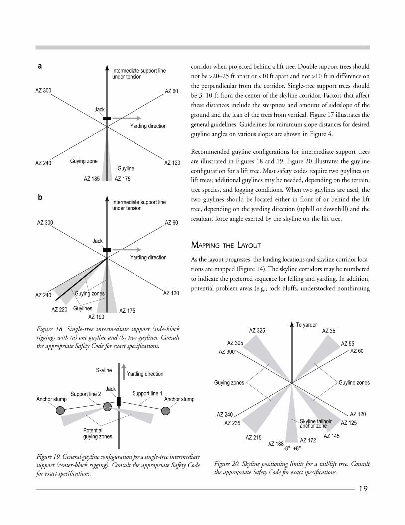
areas) and the felling pattern for long corners or special areas that do not follow a regular layout and yarding pattern should be identified on the map.
A map with a completed setting layout is shown in Figure 21. Some maps will also include the location and description (e.g., species and tree size) of the intermediate support trees, lift trees, tailholds, and anchors. The map shows skyline corridors with a common landing. There are advantages and disadvantages to different patterns of layouts and associated reasons for using them, as mentioned previously.
When the skyline corridor layout for each unit is complete, copies of the layout map are provided to the contract administrator (if applicable), the operator, the hooktender, and the falling crew, at a minimum. It is critical that the falling crew understand the overall unit layout and the falling and yarding sequence so they can fall the timber as needed for the safest and most efficient yarding.
FOLLOW-UP
The final step is to follow up after falling and yarding have begun. This gives the layout person invaluable feedback on how well the layout matches the unit and the harvest system require-ments and allows adjustments as needed to current and future projects.
Roads with surfacingContours 40 ft intervalPlanned sales
3594-21
Ft
Figure 21. Completed corridor layout map with field notes and instructions.

21
TOOLS, TECHNIQUES, AND PROCEDURES TOOLS
The basic tool in laying out skyline corridors is a good map showing accurate unit boundaries. A topographic map is best, but a good planimetric map is suitable. A corrected orthophoto of the unit is ideal. Another key piece of equipment is highly visible flagging, used to mark the centerline of the corridor, support trees, lift tree, tailhold, and anchors. Usually flags at least 12 in. long are hung along the centerline of the corridor at eye height and not more than 50–60 ft apart, such that they are intervisible. Typically, one piece of flagging is tied around support trees at breast height with the knot towards the jack side of the tree. Lift trees have two pieces of flagging at breast height with the knots towards the skyline block side of the tree. One piece
of flagging is tied around the base of anchor stumps and the tailhold, with the knot towards the bell or shackle side of the tree.
Distance measurement tools may be as simple as pacing, a hip chain (string box), or a cloth or fiberglass tape, or as sophisticated as a hand-held laser or electronic distance measuring (EDM) equipment. Instruments for angular measurements may be as simple as a hand or staff compass or as sophisticated as a transit, or even a theodolite. Our preference is pacing or a hip chain for distance and a hand compass. This combination of equipment usually requires only one person for field operation and is inexpensive and easy to carry.
The centerline of the skyline corridor generally needs to be 5 ft or less laterally from the lift tree or tower location; the hand compass and careful pacing or use of a hip chain are usually sufficient to achieve this level of accuracy. In general, the longer the corridors and the more rugged and variable the terrain, the greater is the need for more care and, possibly, more sophisticated equipment to meet accuracy requirements. At present, GPS systems are not recommended for skyline corridor layout, as the accuracy needed for corridor location is difficult to attain because of the heavy canopy cover.
TECHNIQUES
The technique used for laying out a skyline corridor involves some basic principles of surveying and the prolongation of a straight line (Figure 22). Whether a corridor is started at the landing or at the tailhold, a flagging marker is set indicating the position of the tower on the landing or of the tailhold at the back end of the corridor. The first shot is taken along a predetermined bearing or azimuth (obtained from the harvest unit layout map) to the first ribbon loca-tion. Once the first ribbon is tied off, it is a matter of backsighting
To tailhold
Landing
3594/22
10
9
8
7
6
5
4
1
2
3
Keep moving ahead and thenbacksighting on the previous two ribbons (as a minimum) to maintainalignment until the end of the corridor
Set ribbon by visually lining up 7and 5 (as a minimum)
Move ahead approximately samedistance between 7 and 5 wherethey are both still visible
Set ribbon by visually lining up 5and 1 (as a minimum)
Move ahead approximately samedistance between 1 and 5— about30–50 feet—where both are still visible
Set ribbon by visually lining up towermarker 1 and backsight ribbon 3
Project bearing forward from towerlocation 1 to next ribbon 5
Mark tower location
Project corridor bearing to backsight
Set backsight ribbon
Figure 22. Procedure for prolongation of a straight line for corridor location.

22
from the current position to the previous ribbons and prolonging a straight line. Although this is usually done by eye without the aid of surveying equipment, a staff compass can improve the accuracy of the backsight. Occasionally, as work progresses along the corridor, the bearing of the line is checked with the compass to ensure that it is not diverging because of local attraction or other errors. This is important when an obstacle is encountered along the skyline corridor. To offset around the obstacle, visual rectification (“eyeballing”) and use of the hand compass (Figure 23) ensures prolonging the line of sight in a straight line through the object. If a staff compass or more sophisticated piece of equipment is used, a perpendicular or angular offset may be used to get around the obstacle and keep the corridor centerline straight (Figure 24).
One key component of successful prolongation of a backsight is prolonging only a distance that is very similar to the distance of the backsight. Prolongation of a short backsight for a long distance can introduce unacceptable error.
Using a plumb bob to line up the backsight on the preceding rib-bons works well to keep the line straight on steep ground with slope changes, such as when crossing a drainage or sidehill area.
PROCEDURES
Gathering information on a skyline corridor for feasibility and payload analysis is straightforward. A survey of the targeted skyline corridor is completed between the landing and tailhold. The profile may be run from top to bottom, or in reverse. Information collected along the centerline of the corridor includes, but is not limited to, the slope distance and percent slope between each terrain point; location, size, and species of potential intermediate support trees, lift trees or tail trees, tailholds, and other anchors; and any special operations problems (e.g., full suspension over a stream, rock bluffs, etc.). There are similarities and differences in laying out parallel or fan-shaped skyline corridors.
The procedure for laying out parallel skyline corridors is quite simple (Figure 25). Begin the first corridor from the road at a designated bearing. At the end of the corridor, pace off the set lateral yarding distance at 90° from the current corridor to the end of the next cor-ridor. From a suitable tailhold and lift tree, run this corridor back to the roadside landing at the reverse bearing of the first corridor. Once on the road, pace off the set lateral yarding distance to the beginning of the next corridor and continue, repeating the process
To tailhold
Tree
3594/23
4
3
2
B
A
1
(1) Project location of corridor ahead onto tree using the compass to estimate where the line should intersect, A
(2) Project the intersect point through the treeto the other side, B (best visual estimate).
(3) To set ribbon 3 use B as a starting point,then step off to one side of the projected lineuntil ribbons 1 and 2 can be seen (they will not be aligned)
(4) Step back into the estimated alignment using the visual image of ribbons 1 and 2 to align with an estimated projection (5) Repeat steps 3 and 4 a few times andalternate the direction sidestepped to get a point of reference for ribbons 1 and 2 and project their alignment
(6) Once ribbon 3 is set, use the hand compassto check the bearing to B for alignment. If thebearing is off, repeat the above process. If thebearing matches the corridor alignment, continue
(7) To set ribbon 4, follow the process in (3)except use ribbons 1, 2, and 3 to project thealignment visually.
(8) Once ribbon 4 is set, proceed as usual to set the next ribbon by aligning ribbons 3 and 4 for a backsight.
3594/24
To tailhold
Tree
6
5
2
4
3
1
(1)Set a survey point 1 as close to the tree aspossible 2.
(2) Turn a 90° angle from the forward bearing,measure a set distance, and set survey point 3.
(3) At 3 turn a 90° angle to a bearing parallelto the corridor bearing, measure a distance,and set a survey point 4.
(4) At 4 turn a 90° angle, measure the sameoffset distance between 2 and 3, and setsurvey point 5.
(5) At 5 turn a 90° angle to original corridorbearing.
(6) From 5, project corridor bearing ahead toset 6.
(7) Continue projecting corridor by backsightingon previous survey points and using the frontsight to align the next survey point.
Figure 23. Hand compass method to offset around obstacles in corridor.
Figure 24. Staff compass method to offset around obstacles in corridor.

23
used to run the first corridor. If landings are a concern on the road, another option is to pace the distance to the next landing on the road before running the first cor-ridor to check the landing location, and then match that distance at the back end of the first corridor. Continue with either one of these procedures until the topography, road width and conditions, or both justify another type of layout (e.g., fan-shaped corridor pattern).
Laying out fan-shaped corridors can get more complicated and may involve more effort. On the unit map, tentatively lay out the skyline corridors to scale for an entire setting from a common landing. Begin on
one side of the setting at a predesignated bearing calculated from the harvest unit map. Run in the centerline for this corridor on the ground from the landing to the tailhold. If the layout is good on the ground, there are two alternatives for running in the next skyline road (Figure 26).
The first option is to return to the landing to begin the second skyline road from the exact location of the first. The length and bearing for the second skyline road are calculated from the map harvest unit by using the scaled horizontal distance and trigonometry of a right triangle to figure the angle difference in the bearings. The remaining setting roads are laid out in the same manner. Although each corridor begins at the exact desired location on the landing, this involves some unproductive time walking back to the landing after each corridor. Table 4 summarizes the angle to turn to locate the next skyline road in this manner with various tailhold (or lift tree) spacings.
A second option, on completion of the first corridor, is to pace off the horizontal offset distance to the tailhold of the next corridor. Measure the length of the corridor on the map. Using the same mathematical technique mentioned above, calculate the bearing of the second corridor. From the tailhold, run the second skyline corridor back to the landing. When success-ful, this procedure reduces the amount of unproductive time spent walking back to the landing after each corridor. In addition, beginning at the tailhold ensures that a suitable anchor and lift tree are located for the corridor. This
Culvert
S 1° W
N 1° E
S 1° W
N 1° E
S 1° W
N 1° E
End
Tower locationRoad
Start
3594/25
Figure 25. Layout of parallel skyline corridors.
3594/26
12
1
2
3
Bearing for corridor 1: S 10° W
From map: Length 1 = 800‘ Offset to 2 = 200‘ Calculated angle = tan-1 (200/800) Angle = 14°
Bearing for corridor 2 : S 4° E
Return to the landing and run incorridor 2 at the S 4° E bearing
Run in corridor 1: S 10° W
Pace at 90° 200 ft to the end of thenext corridor (Leg 2)
Calculate the bearing for the nextcorridor same as before; bearing forLeg 3 is S 4° E
Run in the second corridor(Leg 3) at N 4° W from thetailhold up to the landing
200‘
800’
Landing
Landing
Option 1: Return to landing
Option 2: Run line back up hill
Figure 26. Layout of a fan-shaped corridor pattern.

24
technique works well when used by an exceptionally skilled layout expert in areas with relatively short yarding distances (<1000 ft), brush that is not too heavy, uniform topography, and well-stocked stands.
When one is working with a distinctive ridgeline system, an-other option is to center the first corridor of the setting down the ridgeline. The remainder of the corridors for the setting can be laid in on either side of this corridor by using the above techniques.
On occasion, when a skyline corridor is run on the ground, it may not line up with intermediate support trees, a lift tree, the landing, or a tailhold anchor. If the distance along the skyline corridor is known or can be determined from a map and the offset distance to the desired tree or set of trees is known, simple trigonometry may be used to calculate the angle offset to be applied to the bearing of the current corridor to get a corrected bearing. Beginning at a known point, the corridor may be rerun at the corrected bearing (Figure 27). Table 5 is a table of offset distances and angle adjustments to correct the corridor alignment from the landing to line up with the lift tree and/or tailhold.
Table 4. Angle (°) to turn from current road to locate next road (starting at landing).
Horizontal distance Tailhold spacing (ft) to tailhold (ft) 50 100 150
100 29.0 60.0 97.2 200 14.4 29.0 44.0 300 9.6 19.2 29.0 400 7.2 14.4 21.6 500 5.7 11.5 17.3 600 4.8 9.6 14.4 700 4.1 8.2 12.3 800 3.6 7.2 10.8 900 3.2 6.4 9.6 1000 2.9 5.7 8.6 1100 2.6 5.2 7.8 1200 2.4 4.8 7.2 1300 2.2 4.4 6.6 1400 2.0 4.1 6.1 1500 1.9 3.8 5.7
Table 5. Angle (°) to adjust original azimuth in order to calculate new azimuth from landing to tailtree.
Horizontal distance Offset to tailhold (ft) to tailhold (ft) 10 20 30 40 50
100 5.7 11.5 17.3 23.1 29.0 200 2.9 5.7 8.6 11.5 14.4 300 1.9 3.8 5.7 7.6 9.6 400 1.4 2.9 4.3 5.7 7.2 500 1.1 2.3 3.4 4.6 5.7 600 1.0 1.9 2.9 3.8 4.8 700 0.8 1.6 2.5 3.3 4.1 800 0.7 1.4 2.1 2.9 3.6 900 0.6 1.3 1.9 2.5 3.2 1000 0.6 1.1 1.7 2.3 2.9 1100 0.5 1.0 1.6 2.1 2.6 1200 0.5 1.0 1.4 1.9 2.4 1300 0.4 0.9 1.3 1.8 2.2 1400 0.4 0.8 1.2 1.6 2.0 1500 0.4 0.8 1.1 1.5 1.9
• Add the angle to your original azimuth if you offset to the right from your original line to locate a tailtree.
• Subtract the angle from your original azimuth if you offset to the left from your original line to locate a tailtree.
• Right and left offsets are defined off the original line, with your back to the landing.
• To flag the new corridor from the tail tree to the landing, either add 180° to the new azimuth to get the back azimuth, or backsight with the south needle aligned with the north declination arrow.
3594/27
Corridor bearing= S 10° W
Distance to lift tree (measuredor scaled) = 1000 ft
Calculate from landing adjusted angle: Angle = tan-1 (50/1000) Angle = 2.9°
Calculate new bearing: S 10° W - 2.9° = S 7.1° W from the landing or N 7.1° E from the lift tree
Landing
Missed lift treeby 50 ft
Figure 27. Application of a corrected bearing.

25
LITERATURE CITED
Anderson, JW, and MR Pyles. 1992. Guying Single-Tree Intermediate Supports. Forest Engineer-ing Institute. Forest Engineering Department, Oregon State University, Corvallis.
Forest Engineering Institute Notebook. 1994. Forest Engineering Department, Oregon State University, Corvallis.
Kellogg, LD, GV Milota, and B Stringham. 1998. Logging Planning and Layout Costs for Thinning: Experience from the Willamette Young Stand Project. Research Contribution 20, Corvallis Forest Research Laboratory, Oregon State University, Corvallis.
Kellogg, LD, GV Milota, and B Stringham. 2002. Timber Harvesting to Enhance Multiple Resources, pp. 135-171 in Forest and Stream Management in the Oregon Coast Range, Hobbs, SD, JP Hayes, RL Johnson, GH Reeves, TA Spies, JC Tappeiner II, and GE Wells, eds. Oregon State University Press, Corvallis.
LOGGERPC V. 4.0. 2002. Oregon State University Department of Forest Engineering, Corvallis.
McNeel, JF, and K Dodd. 1996. Trends in Commercial Cable Thinning in Western Washing-ton, pp. 79–86 in Proceedings of a Joint Symposium of IUFRO 3.06 Forest Operations Under Mountainous Conditions and the Ninth Pacific Northwest Skyline Symposium, May 13–16, 1996, Campbell River, BC, Canada. I Hedin and S Sambo, eds. FERIC, Vancouver, BC, Canada.
Pyles, MR. 1991. Field Layout Considerations for Evaluating Cable Logging System Guyline Anchor Locations: The Guyline Doughnut. Forest Engineering Institute. Forest Engineering Department, Oregon State University, Corvallis.
Studier, DD, and VW Binkley. 1974. Cable Logging Systems. Division of Timber Management, USDA, Portland OR.

Oregon State University is an affirmative-action, equal-opportunity employer.

Non-Profit Org.U.S. Postage
PAIDCorvallis, OR
Permit No. 200
Forestry Communications GroupOregon State University256 Peavy HallCorvallis, OR 97331-5704
Address Service Requested