PRACTICAL GUIDANCE FOR THE DESIGN AND CONSTRUCTION …
185
PRACTICAL GUIDANCE FOR THE DESIGN AND CONSTRUCTION OF LIQUID-RETAINING STRUCTURES AND RESEARCH TOWARDS THE REVISION OF SANS 10100-3 Report to the Water Research Commission by Prof C Viljoen, Prof JV Retief, Dr NPJ de Koker, Dr C McLeod and Mr HG Kruger University of Stellenbosch Report no. 2514/1/20 ISBN 978-0-6392-0143-6 May 2020
Transcript of PRACTICAL GUIDANCE FOR THE DESIGN AND CONSTRUCTION …

PRACTICAL GUIDANCE FOR THE DESIGN AND CONSTRUCTION OF
LIQUID-RETAINING STRUCTURES AND RESEARCH TOWARDS THE REVISION
OF SANS 10100-3
Report
to the Water Research Commission
by
Prof C Viljoen, Prof JV Retief, Dr NPJ de Koker, Dr C McLeod
and Mr HG Kruger
University of Stellenbosch
Report no. 2514/1/20 ISBN 978-0-6392-0143-6
May 2020

ii
Obtainable from: Water Research Commission Private Bag X03 Gezina, 0031 South Africa [email protected] or download from www.wrc.org.za
DISCLAIMER This report has been reviewed by the Water Research Commission (WRC) and approved for
publication. Approval does not signify that the contents necessarily reflect the views and policies of the WRC, nor does mention of trade names or commercial products constitute endorsement or
recommendation for use.

Practical guidance for the design and construction of liquid-retaining structures
iii
EXECUTIVE SUMMARY
The successful drafting of a standard for the design of liquid-retaining concrete structures (Viljoen, 2013) provided the platform to launch a comprehensive project to compile and implement best practices for the specification, design and construction of liquid-retaining structures for South Africa.
To this end, WRC Project K5/2514/1, had the following main aims:
• Develop a complementary suite of documentation to aid the design, specification and construction of liquid-retaining structures
• Extend the research basis for future revisions of SANS 10100-3 • Contribute to training and capacity building through seminars and academic activities • Provide a framework for future initiatives
To achieve durable and leak-tight liquid-retaining structures, a suitable design must be well executed in construction, according to adequate specifications.
This project developed three guidelines that were intended to serve project teams in their task to deliver high-quality liquid-retaining structures:
• A guide to the analysis and design of liquid-retaining structures, including example calculations to the requirements of SANS 10100-3
• A guide on tender specifications that extends the scope of SANS 2100 CC1 to be generally applicable to the construction of liquid-retaining structures and that can be readily modified to make provision for particular liquid-retaining structure projects
• A guide for site personnel and design engineers focusing on construction practices that are required to achieve the additional requirements of durability and leak tightness for liquid-retaining structures
The research basis for future revisions of the South African National Standard (SANS), SANS 10100-3, was extended by a careful assessment of crack width prediction models in terms of their fundamental assumptions and accuracy when compared to experimental results. Together with an assessment of leakage rates and self-healing as a function of crack widths, practical recommendations could be made for models and crack limits to be considered for adoption in SANS 10100-3. Design values were derived for T1 (heat of hydration) and T2 (seasonal temperature variation) to be used in design for estimating early-age and long-term thermal cracking, respectively, based on local data regarding South African concretes and climate.
Dissemination seminars presented in Stellenbosch and Johannesburg as a series of three one-day seminars covered basic design, construction considerations, and the advanced design of liquid-retaining structures. These were well attended by all the relevant stakeholders, ranging from client organisations and water authorities, professional design engineers and technicians, to the construction industry and specialist companies serving the industry. The combined attendance amounted to 255 man-days, with participant feedback on the technical content being particularly positive.
The project contributed significantly to capacity building through the involvement of 17 students, five academics and several industry participants. In this regard, financial support was aimed at facilitating student training and research, including conference attendance. The project supported three PhD students and four MEng students, producing research that resulted in five International Scientific Indexing (ISI)-listed journal publications and seven peer-reviewed conference publications. Moreover, this project contributed meaningfully to capacity development in under-represented groups in science, technology, engineering and mathematics. The group of postgraduate students comprised 71% female representation, and 43% was from the black, coloured and Indian population groups.

Practical guidance for the design and construction of liquid-retaining structures
iv
An academic research programme is essential to serve as a knowledge base and development of input to such a wide-ranging project. The research programme enabled the training of young engineers as potential future expert practitioners and industry leaders. It also facilitated research on the transfer of procedures developed from elsewhere to make provision for local conditions, and provided the opportunity for academic staff to develop as experts that could serve at a national level, while engaging at an international level to benefit from global development and advances.
A framework for future initiatives identified the main sources of failure in water and sanitation infrastructure. The optimal operation and maintenance of these structures are recognised as critical to ensure that our infrastructure remains available and functional to serve our growing population. Training initiatives are proposed based on documented maintenance strategies, which are aimed at municipal staff and engineering graduates, emphasising theoretical and practical questions according to the target audience. Research contributions to support optimal maintenance initiatives are identified.

Practical guidance for the design and construction of liquid-retaining structures
v
ACKNOWLEDGEMENTS
The authors would like to acknowledge the WRC for funding Project K5/2514/1, which has contributed significantly towards the development of useful design documentation that will serve the South African civil engineering community well in years to come.
A special thanks is due to the project’s Reference Group for making their time and expertise available and for constructive contributions to shape the project:
Wandile Nomquphu (Chair) Water Research Commission Dr A Bester Hatch Goba AJ Smith Joint Structural Division Prof M Gohnert University of the Witwatersrand C Koen iX Engineers R Kroger Aurecon HG Kruger HGK Consulting E Lillie Knight Piesold M Martin Hiload Inyanga Construction S Naidu Naidu Consulting Prof JA Wium Stellenbosch University
Stellenbosch University is thanked for in-kind contributions of expertise, space and supplementary funding.
Several industry experts, particularly Mr K Bultman, Mr T Dubber, Mr H Bosman, Mr D Erasmus, Mr N Kruger, Mr D Middleton and Mr W Smith, provided valuable input to this development.

Practical guidance for the design and construction of liquid-retaining structures
vi
TABLE OF CONTENTS
EXECUTIVE SUMMARY .................................................................................................................... III ACKNOWLEDGEMENTS ................................................................................................................... V LIST OF TABLES ............................................................................................................................... XI LIST OF FIGURES ........................................................................................................................... XIII LIST OF ABBREVIATIONS .............................................................................................................. XV CHAPTER 1: INTRODUCTION AND OBJECTIVES .......................................................................... 1 1.1 Introduction to the project ................................................................................................... 1 1.2 Objectives of the project ..................................................................................................... 1
1.2.1 Development of practical documents to aid the design and construction of liquid-retaining structures ....................................................................................... 2
1.2.2 Making research provision for future revisions of SANS 10100-3 ......................... 3 1.2.3 Capacity development and dissemination ............................................................. 3 1.2.4 Framework for future initiatives .............................................................................. 4
CHAPTER 2: DESIGN GUIDANCE ON T1 AND T2 VALUES ............................................................ 5 2.1 Introduction ............................................................................................................... 5
2.1.1 Thermally induced cracking of reinforced concrete reservoirs .............................. 5 2.1.2 Design values for temperature reductions T1 and T2 ............................................. 5 2.1.3 South African standard for the design of reinforced concrete reservoirs............... 6
2.2 Objectives ............................................................................................................... 6 2.3 Development of T1 design values ....................................................................................... 7
2.3.1 Introduction ..................................................................................... 7 2.3.2 Prediction models ..................................................................................... 7 2.3.3 T1 design value ..................................................................................... 9 2.3.4 Important parameters, their influence on T1, and related assumptions ............... 10 2.3.5 Sensitivity study ................................................................................... 19 2.3.6 Derivation of T1 design values for walls ............................................................... 20 2.3.7 Adjustments to T1 ................................................................................... 26
2.4 Temperature differentials ∆T ............................................................................................ 28 2.5 Development of T2 design values ..................................................................................... 29
2.5.1 Introduction ................................................................................... 29 2.5.2 Available climatic data ................................................................................... 30 2.5.3 Derivation of T2 design values ............................................................................. 32
2.6 Conclusions ............................................................................................................. 34 2.6.1 Design values for the early-age temperature drop T1 .......................................... 34 2.6.2 Design values for temperature differential ∆T ...................................................... 35 2.6.3 Design values for seasonal temperature drop T2 ................................................ 35
2.7 Recommendations ............................................................................................................ 35 CHAPTER 3: DESIGN GUIDE WITH EXAMPLE CALCULATIONS ............................................... 36 3.1 Introduction ............................................................................................................. 36 3.2 Liquid-retaining structures ................................................................................................ 36
3.2.1 General considerations ................................................................................... 36 3.2.2 Rectangular tanks ................................................................................... 36 3.2.3 Circular tanks ................................................................................... 37

Practical guidance for the design and construction of liquid-retaining structures
vii
3.3 Minimum and thermal reinforcement ................................................................................ 38 3.3.1 Theory (BS 8007 App A/SANS 10100-3 7.3.4(2) and Apps L and M) ................. 38 3.3.2 Example ................................................................................... 40
3.4 Calculation of crack widths due to flexure ........................................................................ 41 3.4.1 Theory (BS 8007 App B/SANS 10100-3 7.3.4(1)) ............................................... 41 3.4.2 Example ................................................................................... 44
3.5 Calculation of crack widths due to tension ....................................................................... 46 3.5.1 Theory (BS 8007 App B/SANS 10100-3 7.3.4(1)) ............................................... 46 3.5.2 Example ................................................................................... 47
3.6 Calculation of crack widths for combined flexure and direct tension ................................ 47 3.7 Design of circular reservoir wall for different restraint conditions ..................................... 47
3.7.1 Wall sliding on base ................................................................................... 48 3.7.2 Wall pinned to base ................................................................................... 48 3.7.3 Wall fixed to base ................................................................................... 51 3.7.4 Comparison of three restraint options .................................................................. 53
3.8 Influence of soil-structure interaction on circular reservoir wall forces ............................. 53 3.9 Design of the wall of the circular reservoir ........................................................................ 56
3.9.1 Forces and moments ................................................................................... 57 3.9.2 Design options ................................................................................... 57 3.9.3 Minimum reinforcement ................................................................................... 57 3.9.4 Reinforcement for thermal and moisture effects .................................................. 58 3.9.5 Vertical design of wall ................................................................................... 58 3.9.6 Horizontal design of wall ................................................................................... 60 3.9.7 Shear ................................................................................... 61
3.10 Design of a rectangular tank wall ...................................................................................... 62 3.10.1 Analysis ................................................................................... 62 3.10.2 Vertical design of long wall .................................................................................. 63 3.10.3 Horizontal design of long wall .............................................................................. 65
3.11 Conclusion ............................................................................................................. 66 CHAPTER 4: TENDER SPECIFICATIONS FOR LIQUID-RETAINING STRUCTURES ............... 67 4.1 Introduction and scope ..................................................................................................... 67 4.2 Standard specifications ..................................................................................................... 67
4.2.1 SANS 1200 ................................................................................... 67 4.2.2 SANS 2100 ................................................................................... 68
4.3 Specification for a generic liquid-retaining structure ......................................................... 68 4.3.1 Requirements for liquid-retaining concrete structures ......................................... 68 4.3.2 Guide to specification data ................................................................................... 69
4.4 Conclusion ............................................................................................................. 70 CHAPTER 5: CONSTRUCTION GUIDELINES FOR LIQUID-RETAINING STRUCTURES ........ 71 5.1 Scope and introduction ..................................................................................................... 71 5.2 Administration ............................................................................................................. 71
5.2.1 Site personnel ................................................................................... 71 5.2.2 Construction project brief ................................................................................... 71 5.2.3 Quality control ................................................................................... 72

Practical guidance for the design and construction of liquid-retaining structures
viii
5.3 Loadings ............................................................................................................. 72 5.3.1 Construction loads ................................................................................... 72 5.3.2 Permanent loadings ................................................................................... 72
5.4 Concrete ............................................................................................................. 73 5.4.1 General ................................................................................... 73 5.4.2 Concrete mix design ................................................................................... 73 5.4.3 Compaction ................................................................................... 75 5.4.4 High evaporation concreting ................................................................................ 75 5.4.5 Hot weather concreting ................................................................................... 77 5.4.6 Cold weather concreting ................................................................................... 77 5.4.7 Pneumatically applied mortar ............................................................................... 77 5.4.8 Cast-in-place walls ................................................................................... 78
5.5 Reinforcement ............................................................................................................. 78 5.5.1 Quality control of reinforcement ........................................................................... 78
5.6 Formwork ............................................................................................................. 79 5.6.1 Design of formwork ................................................................................... 79 5.6.2 Types of formwork ................................................................................... 79 5.6.3 Details ................................................................................... 80
5.7 Repair work ............................................................................................................. 80 5.7.1 General ................................................................................... 80 5.7.2 Cracks ................................................................................... 80 5.7.3 Honeycombing ................................................................................... 81 5.7.4 Blow holes ................................................................................... 81
5.8 Drainage ............................................................................................................. 81 5.8.1 General ................................................................................... 81 5.8.2 Subsoil drainage ................................................................................... 81 5.8.3 Wall drainage ................................................................................... 81
5.9 Joints ............................................................................................................. 82 5.9.1 General ................................................................................... 82 5.9.2 Movement joints ................................................................................... 82 5.9.3 Construction joints ................................................................................... 83 5.9.4 Casting sequence ................................................................................... 84 5.9.5 Waterstops ................................................................................... 84 5.9.6 Joint fillers ................................................................................... 85 5.9.7 Joint sealants ................................................................................... 86
5.10 Protection and curing ........................................................................................................ 86 5.10.1 General ................................................................................... 86 5.10.2 Protection ................................................................................... 87 5.10.3 Curing with water ................................................................................... 87 5.10.4 Curing with liquid-curing compounds ................................................................... 87 5.10.5 Curing by covering ................................................................................... 88
5.11 Testing for water tightness ................................................................................................ 88 5.11.1 Planning for testing ................................................................................... 88 5.11.2 Disinfection ................................................................................... 88

Practical guidance for the design and construction of liquid-retaining structures
ix
5.12 Retrospection ............................................................................................................. 89 5.13 Design considerations ...................................................................................................... 89
5.13.1 Tender specifications and information on drawings ............................................. 89 5.13.2 Structural design ................................................................................... 90 5.13.3 Joint system design ................................................................................... 91 5.13.4 Steelwork, pipework, mechanical and electrical items ......................................... 93 5.13.5 Overflow, ventilation and pressure-relief valves .................................................. 94
CHAPTER 6: CRACK CONTROL PROVISIONS: ASSESSMENT AND RECOMMENDATION .......................................................................................................... 96
6.1 Introduction ............................................................................................................. 96 6.1.1 SANS 10100-3 ................................................................................... 96 6.1.2 Cracking in concrete liquid-retaining structures ................................................... 96 6.1.3 Crack width prediction models ............................................................................. 96
6.2 Objectives ............................................................................................................. 97 6.3 Prediction of load-induced crack widths ........................................................................... 97
6.3.1 Overview ................................................................................... 97 6.3.2 Prediction models ................................................................................... 99 6.3.3 Design situations, load types and durations ...................................................... 104 6.3.4 Comparison to experimental results .................................................................. 106 6.3.5 Assessment of required reinforcement needs ................................................... 108
6.4 Prediction of restraint-induced crack widths ................................................................... 111 6.4.1 Restraint-induced actions and restraint types .................................................... 111 6.4.2 Prediction models and input parameters for South Africa ................................. 112 6.4.3 Practical design considerations ......................................................................... 113
6.5 Crack width limits ........................................................................................................... 113 6.5.1 Principles ................................................................................. 113 6.5.2 Discussion of available research ....................................................................... 114 6.5.3 Limits from various design standard formulations ............................................. 116
6.6 Minimum reinforcement requirements ............................................................................ 117 6.7 Recommendations for SANS 10100-3 ............................................................................ 118
6.7.1 Principles ................................................................................. 118 6.7.2 Prediction model for load-induced crack widths ................................................ 119 6.7.3 Prediction model for restraint-induced crack widths .......................................... 121 6.7.4 Crack width limits ................................................................................. 122 6.7.5 Minimum reinforcement ................................................................................. 123
6.8 Conclusion ........................................................................................................... 123 CHAPTER 7: DISSEMINATION AND CAPACITY BUILDING ...................................................... 125 7.1 Introduction ........................................................................................................... 125 7.2 Dissemination seminars .................................................................................................. 125
7.2.1 Introduction ................................................................................. 125 7.2.2 Content ................................................................................. 125 7.2.3 Presenters ................................................................................. 126 7.2.4 Attendance ................................................................................. 126
Practical guidance for the design and construction of liquid-retaining structures
x
7.3 Academic dissemination and capacity building .............................................................. 127 7.3.1 Students ................................................................................. 127 7.3.2 Staff development ................................................................................. 129 7.3.3 Attendance of international conferences and research publications ................. 129
CHAPTER 8: FRAMEWORK FOR FUTURE INITIATIVES .......................................................... 131 8.1 Introduction ........................................................................................................... 131 8.2 Sources of failure in water and sanitation infrastructure ................................................. 132
8.2.1 Operational failures in mechanical plants .......................................................... 132 8.2.2 Reticulation losses ................................................................................. 133 8.2.3 Loss of integrity in retaining structures .............................................................. 134
8.3 Need for maintenance awareness and training .............................................................. 135 8.3.1 Skills needs for maintenance ............................................................................. 135 8.3.2 Proposed training programme ........................................................................... 136
8.4 Conclusions ........................................................................................................... 137 CHAPTER 9: CONCLUSIONS ....................................................................................................... 138 CHAPTER 10: RECOMMENDATIONS FOR FUTURE WORK .................................................... 140
10.1 Optimal maintenance of existing water and sanitation infrastructure ................ 140 10.2 Continued revision and updating of SANS 10100-3 .......................................... 140
REFERENCES ................................................................................................................................ 141 APPENDIX A: SPECIFICATION DATA FOR GENERIC LIQUID-RETAINING
STRUCTURES .................................................................................................................. 149 APPENDIX B: SANS 1200 G VS SANS 2100 CC1: CURSORY COMPARISON OF
TECHNICAL CONTENT ................................................................................................... 167

Practical guidance for the design and construction of liquid-retaining structures
xi
LIST OF TABLES
Table 1.1: Objectives and deliverables of K5/2514/1 .......................................................................... 2
Table 2.1: Design heat curve characteristics of concretes used in the Bamforth model .................. 14
Table 2.2: Conservative estimates of binder content for different concretes (adapted from Bamforth,
2007) ................................................................................................................................. 14
Table 2.3: Proposed values of thermal conductivity of concrete (Bamforth, 2007) ........................... 16
Table 2.4: Average wind speeds (m/s) for South African cities (SAWS, 2017) ................................. 16
Table 2.5: Summary of assumed input values and assessment of the implied level of conservatism..
.......................................................................................................................................... 19
Table 2.6: Sensitivity of T1 to changes in various parameters from a reference case ...................... 20
Table 2.7: Temperature differentials (ºC) for walls in steel formwork ................................................ 29
Table 2.8: Temperature differentials (ºC) for walls in plywood formwork .......................................... 29
Table 2.9: Indicative seasonal temperatures across central South Africa (adapted from Kruger, 2008),
shown as the highest monthly or seasonal three-month averages .................................. 30
Table 2.10: Standard deviation of ΔTm (°C) based on representative seasonal values (Kruger, 2016)
.......................................................................................................................................... 32
Table 2.11: Values for T2 based on geographic zones and construction season ............................... 34
Table 3.1: Summary of reinforcement ............................................................................................... 41
Table 3.2: Value of static modulus of elasticity of concrete and modular ratio ................................. 42
Table 3.3: Effect of wall restraint ....................................................................................................... 53
Table 3.4: Theoretical forces and moments in reservoir wall ............................................................ 55
Table 4.5: Results from FE analyses on reservoir ............................................................................ 55
Table 3.6: Theoretical vertical moment Ms and horizontal tension Ts ............................................... 57
Table 3.7: Summary of reinforcement in horizontal direction ............................................................ 58
Table 4.1: Breakdown of additional requirements for liquid-retaining structures and related clause
references to provisions in the specification data provided in Addendum A ...................... 69
Table 6.1: Comparison of design standard formulations for the control of flexure cracking ............... 100
Table 6.2: Comparison of design standard formulations for the control of tension cracking .............. 101
Table 6.3: Summary of ki values as applied to maximum crack spacing formulation ........................ 102
Table 6.4: Summary of calculations of SLS ring tension and vertical bending moment using Table
2.75 of Reynolds et al (2008) for circular reservoir configuration ................................... 105
Table 6.5: Model uncertainty statistical parameters of crack prediction models (all data) ................. 106
Table 6.6: Model uncertainty statistical parameters of crack prediction models (< 0.4 mm cracks) .. 107
Table 6.7: Prediction bias of different crack prediction models .......................................................... 107
Table 6.8: Parameters of representative liquid-retaining structures ................................................... 108
Table 6.9: Comparison of standardised formulations for the control of edge and end restraint-induced
cracking: basic formulations ........................................................................................... 112
Table 6.10: Comparison of standardised formulations for the control of edge and end restraint-induced
cracking: strain formulation ............................................................................................. 112

Practical guidance for the design and construction of liquid-retaining structures
xii
Table 6.11: Comparison of standardised formulations for the control of edge and end restraint-induced
cracking: input parameters ............................................................................................. 113
Table 6.12: Permissible crack widths for autogenous healing (Edvardsen, 1999) ............................. 115
Table 6.13: Tightness classes from EN 1992-3 .................................................................................. 117
Table 6.14: Comparison of crack width limits from various standards ............................................... 117
Table 6.15: Comparison of minimum reinforcing areas ...................................................................... 118
Table 6.16: Tightness classes proposed for SANS 10100-3 .............................................................. 123
Table 6.17: Summary of specified and proposed crack width limits for tightness class 1 .................. 123
Table 6.18: Adjusted through crack width limits for cyclic loading, tightness class 1........................ 123
Table 7.1: Number of attendees at the two venues ......................................................................... 127
Table 7.2: Postgraduate and final-year students involved in research related to the project ......... 127
Table 10.1: Some research issues relating to liquid-retaining structures in the South African context ..
........................................................................................................................................ 140

Practical guidance for the design and construction of liquid-retaining structures
xiii
LIST OF FIGURES
Figure 2.1: Measured temperature rise values compared to Bamforth’s predictions (Bamforth, 2007)
......................................................................................................................... 8
Figure 2.2: Adiabatic heat curves of different clinker cements (Ballim and Graham, 2004b) .......... 11
Figure 2.3: Comparison of total heat profiles of low and high fineness (2,640 cm2/g and 4,980 cm2/g)
cements produced from two clinker types (A and B) (Graham et al., 2011) .................. 11
Figure 2.4: Adiabatic heat curves of different mortar blends (Dhir et al., 2006) ................................... 12
Figure 2.5: Adiabatic heat curves of different slag binder combinations available in South Africa
(Alexander et al., 2003) .................................................................................................. 12
Figure 2.6: Adiabatic heat curves of different South African mortar blends (Beushauzen et al., 2012)
....................................................................................................................... 13
Figure 2.7: Design curves for adiabatic heat (10% probability of exceedance values) of concretes
used in the Bamforth model (Bamforth, 2007) ............................................................... 13
Figure 2.8: Adiabatic temperature rise curve for a concrete mix of 100% CEM I with 400 kg/m3 binder
content, a specific heat of 1 kJ/kg ºC and a wet density of 2,400 kg/m3 ....................... 15
Figure 2.9: Mean summer temperatures of South Africa (Kruger, 2008) ......................................... 17
Figure 2.10: The T1 values for walls of CEM I concrete (of different binder content) ........................ 21
Figure 2.11: The T1 values for walls of CEM I concrete (of different strength classes) ..................... 21
Figure 2.12: The T1 values for walls with concrete (of different binder content) containing GGBS ... 22
Figure 2.13: The T1 values for walls with concrete (of different strength classes) containing GGBS 23
Figure 2.14: The T1 values for walls with concrete (of different binder content) containing fly ash ...... 24
Figure 2.15 : The T1 values for walls with concrete (of different strength classes) containing fly ash . 25
Figure 2.16: Change in T1 (per 100 kg/m3 binder) for changes in relative placing temperature,
including active cooling .................................................................................................. 26
Figure 2.17: Change in T1 (per 100 kg/m3 CEM I) for changes in wind speed .................................. 27
Figure 2.18: Change in T1 (per 100 kg/m3 CEM I) for changes in thermal conductivity ..................... 27
Figure 2.19: Change in T1 (per 100 kg/m3 binder) for changes in mean ambient temperature ......... 28
Figure 2.20: General topography of South Africa (GeoCommunity, 2016) ........................................ 31
Figure 2.21: Annual range of mean monthly temperature ΔTm (°C) (Kruger, 2008) ......................... 32
Figure 3.1: Distribution of ring tension and vertical bending moment over the height of the wall .... 38
Figure 3.2: Assumed stress and strain diagram for cracked section, elastic design ....................... 41
Figure 3.3: Definition of acr .............................................................................................................. 44
Figure 3.4: Section under direct tension, assumed stress and strain diagram ................................ 46
Figure 3.5: Finite element model of 6 Mℓ reservoir .......................................................................... 54
Figure 3.6: Wall of 6 Mℓ reservoir ..................................................................................................... 56
Figure 3.7: Rectangular tank ............................................................................................................ 62
Figure 3.8: Vertical moment in long wall .......................................................................................... 63
Figure 3.9: Horizontal moment and force in corner .......................................................................... 63

Practical guidance for the design and construction of liquid-retaining structures
xiv
Figure 6.1: Behaviour of a reinforced prismatic bar subjected to imposed deformation (crack
formation stage) ............................................................................................................. 98
Figure 6.2: Simplified load – strain relation for a reinforced prismatic bar subjected to tension ...... 99
Figure 6.3: No-slip mechanism of cracking: relationship between c and transfer length (from the old
British Code for structural concrete, CP 110) .............................................................. 103
Figure 6.4: Rectangular (left) and circular reservoir (right) wall configurations ............................. 105
Figure 6.5: Experimental vs MC 2010 and BS 8007 predicted crack widths for: (a) short-term
bending, (b) long-term bending, (c) short-term tension and (d) long-term tension ...... 108
Figure 6.6: Reinforcement ratios for short-term bending, wk = 0.2 mm ......................................... 109
Figure 6.7: Reinforcement ratios for long-term bending, wk = 0.2 mm .......................................... 110
Figure 6.8: Reinforcement ratios for short-term tension, wk = 0.2 mm .......................................... 110
Figure 6.9: Reinforcement ratios for long-term tension, wk = 0.2 mm ........................................... 110
Figure 6.10: Comparison of EN 1992-3 through crack width limits to research findings (from Jones,
2008) ..................................................................................................................... 115
Figure 6.11: Reinforcement implication of crack width limit in MC 2010 formulation (bending and
flexure) ..................................................................................................................... 120
Figure 8.1: Present value of accumulated savings resulting from sustained reductions of 5 to 20% in
water loss volumes, calculated using consumption figures relevant to the City of Cape
Town, and assuming a discount rate of 5%. The estimated replacement value of the Berg
River Dam (adjusted to 2019 values) is shown for comparison. ................................. 134

Practical guidance for the design and construction of liquid-retaining structures
xv
LIST OF ABBREVIATIONS
ACI American Concrete Institute ASR Alkali-silica reaction BS British Standard CEM I (Ordinary Portland) Cement CESMM Civil Engineering Standard Method of Measurement CIRIA Construction Industry Research and Information Association CoV Coefficient of variation EF External face EN European Norms Fib International Federation for Structural Concrete GGBS Ground granulated blast-furnace slag GGCS Corex slag H/h Hydraulic ratio HDPE High-density polyethylene HOR Horizontal IF Inner face ISI International Scientific Indexing MC Model Code MEng Master of Engineering OF Outer face OL Outer layer OPC Ordinary Portland cement PhD Doctor of Philosophy PVC Polyvinyl chloride SABS South African Bureau of Standards SANS South African National Standard SANS 10100-3 (TC Draft) Draft standard for the design of concrete liquid-retaining structures
produced by the SANS 10100-3 Working Group and accepted through an official review and voting process as Technical Committee Draft by SABS TC98-02. It is being prepared for distribution for public comment. It uses EN 1992-3-2006 and BS 8007 as reference base.
SAWS South African Weather Service SAICE South African Institute of Civil Engineers SLS Serviceability limit state STEM Science, technology, engineering and mathematics T1 Temperature drop from the peak hydration temperature at the centre
of the section to the mean ambient temperature T2 Temperature drop from the mean ambient temperature at the time of
casting to the minimum ambient temperature TC Technical Committee UK United Kingdom ULS Ultimate limit state VER Vertical WG Working Group WRC Water Research Commission

Practical guidance for the design and construction of liquid-retaining structures
1
CHAPTER 1: INTRODUCTION AND OBJECTIVES
1.1 INTRODUCTION TO THE PROJECT
A code of practice for liquid-retaining structures forms an important part of the basis from which the quality, durability and maintenance of liquid-retaining infrastructure can be managed in South Africa. The establishment of such a code of practice was the purpose of two previous WRC projects: Project K5/1764 and Project K5/2154/1. The successful completion of these projects provided the platform for launching Project K5/2514/1: a comprehensive project for the compilation and implementation of best practice for the specification, design and construction of liquid-retaining structures for South Africa. The WRC Project K5/2514/1 extends the basis from which local authorities and water authorities can set up systems in a coordinated manner for the management of durable infrastructure.
The WRC Project K5/1764 focused on taking significant steps towards developing a draft standard for the design of liquid-retaining structures for South Arica. The SANS 10100-3 (Draft) document, which originated from WRC Project K5/1764, was developed using European Norms (EN) EN 1992-3 (2006) (Eurocode) as the principal reference document. Clauses in the code were enhanced by extracts from British Standard (BS) BS 8007: 1987. Exclusions and changes from EN 1993-3 comprised a reduction in the scope of the document (excluding silos), defining the temperature range of contained liquids to ambient temperatures (as in BS 8007), and using the concrete crack width criteria from BS 8007. Integral to the development of SANS 10100-3 (Draft) was the relationship of this standard with other standards. Members of the project team participated in working groups for the revision of SANS 10160 (2010) and SANS 10100-1 (2000) so that evaluations were extended to design codes beyond SANS 10100-3 (Draft) alone.
The WRC Project K5/2154/1 furthered the development of SANS 10100-3: Design of liquid-retaining concrete structures through the formal process of standards development in accordance with the requirements and procedures of the South African Bureau of Standards (SABS) for the various stages of assessment and approval, up to the status of voted Technical Committee draft. The project prioritised participation by various interested organisations and the engineering profession, liaising with industry to recruit suitable Working Group members, handling the logistics of Working Group meetings and considering appropriate calibration and harmonisation with related codes SANS 10160: The general procedure and loadings to be adopted in buildings and SANS 10100-1: The structural use of concrete: design. The project took responsibility for creating the background documentation for the Technical Committee draft standard and disseminating results to the broader engineering community. Various remaining issues that required attention were identified, some of which are addressed in WRC project K5/2514/1 (reported on here).
1.2 OBJECTIVES OF THE PROJECT
The WRC project K5/2514/1 has the following main aims:
• Develop a complementary suite of documentation to aid the design, specification and construction of liquid-retaining structures
• Extend the research basis for future revisions of SANS 10100-3 • Contribute to training and capacity building through seminars and academic activities • Provide a framework for future initiatives
Deliverables of the project are listed in Table 1.1. Interim reports were submitted to meet the listed target dates. The referenced chapters of this report fully detail each deliverable. While interim reports formed the basis of the contents of this final report, it was, in some cases, extended.

Practical guidance for the design and construction of liquid-retaining structures
2
Table 1.1: Objectives and deliverables of K5/2514/1
Deliverable Chapter reference
Target date
Development of practical documentation 1.1 Design guideline with example calculations Chapter 3 2018/02/23
1.2 Specification guideline Chapter 4 2017/07/31
1.3 Construction guideline Chapter 5 2017/04/28
Research provision 2.1 Design guidance on T1 and T2 values Chapter 2 2017/02/17
2.2 Crack recommendations Chapter 6 2019/01/31
Training and capacity building 3.1 Dissemination seminars Chapter 7 2018/04/23
3.2 Capacity building Chapter 7 2019/02/28
Recommendations for future work 4.1 Framework for future initiatives Chapter 8 2019/04/26
1.2.1 Development of practical documents to aid the design and construction of liquid-
retaining structures
All structural concrete has to meet the design requirements of the ultimate limit state (ULS) and the serviceability limit state (SLS), including requirements on strength, stability, robustness, durability and deflections. Liquid-retaining structures have to meet additional requirements in terms of durability and leak tightness.
To achieve these requirements, a suitable design must be well executed in construction. A suitable design should conceptually produce a structure that is safe, fit for purpose, economical, practical to construct and easy to maintain. Good construction practice, combined with adequate quality control, should then ensure that these objectives are realised.
Insufficient expertise in design and construction teams for liquid-retaining concrete structures can result in a range of typical mistakes that lead to the inadequate water-tightness and durability of these structures, necessitating costly repairs.
This project developed three guidelines that were intended to serve project teams in their task to deliver high-quality liquid-retaining structures:
Chapter 3 provides a guide for the analysis and design of circular and rectangular liquid-retaining structures. The important influence of boundary condition assumptions is discussed, and example calculations are provided for the design of reinforcement to meet the requirements of SANS 10100-3.
Chapter 4 provides guidance on aspects to be included in tender specifications to facilitate the implementation of good construction practice for most types of liquid-retaining structures. Specification data is developed that extends the scope of SANS 2100 CC1 to be generally applicable to the construction of liquid-retaining structures and that can be readily modified to make provision for particular liquid-retaining structure projects. Additional specifications mainly pertain to ensuring liquid tightness and meeting more stringent durability requirements for the aggressive environments within which these structures often operate.

Practical guidance for the design and construction of liquid-retaining structures
3
Chapter 5 provides construction guidance for liquid-retaining structures, focusing on construction practices that are required to achieve the additional requirements of durability and leak tightness for liquid-retaining structures. The guideline is intended for site personnel, as well as design engineers.
1.2.2 Making research provision for future revisions of SANS 10100-3
The WRC Project K5/2154/1 was concluded in 2015. Its main output was a SABS Technical Committee draft standard for the design of liquid-retaining structures in South Africa. The Working Group responsible for developing SANS 10100-3 consisted of academics and industry experts, including client bodies, design engineers and contractors. During the development, various remaining issues were identified that required attention. The most important of these centered on provisions for the prediction and control of crack widths, as the requirement to limit crack widths to ensure water-tightness and durability usually governs the design.
The need was identified to thoroughly assess provisions for load-induced crack widths to inform the future adoption of provisions in SANS 10100-3. At the time, it was decided to keep the previously used, but outdated and withdrawn, provisions of BS 8007, in spite of SANS 10100-3 being strongly referenced to EN 1992-3.
This interim decision was based on several considerations, mainly the following:
• The crack limits of EN 1992-3 are up to four times more stringent than those of BS 8007, implying significant economic implications, which are deemed unnecessary in light of fairly few complaints regarding water tightness being attributed to the currently used limits of BS 8007, although indications are that, for circular reservoirs (tension dominated), the BS 8007 provisions could be insufficient. Further investigation was deemed necessary to motivate revision of the choice of crack width limits in SANS 10100-3.
• The crack width prediction model of EN 1992 for load-induced cracking gives predictions that differ from those of the BS 8007 prediction model, in some cases significantly so, such as for tension-dominated design situations. An extensive comparison of different available prediction models against available experimental results was deemed necessary.
In Chapter 6, several prediction models for load-induced crack widths are assessed in terms of their fundamental assumptions and accuracy when compared to experimental results. Research on leakage rates and self-healing as a function of crack widths is explored. Finally, practical recommendations are made for models and crack limits to be considered for adoption in SANS 10100-3, including an assessment of the impact on design practice and economy.
A second identified need was to provide design guidance on T1 (heat of hydration) and T2 (seasonal temperature variation) values to be used in design for estimating the early-age and long-term thermal cracking, respectively, based on local data regarding South African concretes and climate. This need is addressed in Chapter 2, where T1 design values are derived based on the numerical models of Bamforth (2007) for South African conditions and a suitable range of design situations. The T2 design values were derived, with possible adjustment for the casting season, for three geographic zones based on the annual range of mean monthly temperatures and its variation.
1.2.3 Capacity development and dissemination
An important aim of the project was to contribute to training and capacity building in structural engineering by engaging in a wide range of activities. Details are provided in Chapter 7. Three seminars were presented based on the technical content developed in this project. These were offered as opportunities for continued professional development to train engineers and technologists employed by client organisations, engineering consultancies and contractors as potential future expert practitioners and industry leaders in the design and construction of liquid-retaining structures.

Practical guidance for the design and construction of liquid-retaining structures
4
The research programme enabled the training of young engineers by engaging nine final-year students. The project supported three PhD students and four MEng students, producing research that resulted in five ISI-listed journal publications and seven peer-reviewed conference publications. It also provided the opportunity for academic staff to develop as experts that can serve at a national level, while engaging at an international level to benefit from global development and advances.
1.2.4 Framework for future initiatives
In Chapter 8, a framework for future initiatives identified the main sources of failure in water and sanitation infrastructure, as well as the technical insufficiencies that contribute to these. The optimal operation and maintenance of these structures are recognised as critical to ensure that our infrastructure remains available and functional to serve our growing population. Training initiatives are proposed based on documented maintenance strategies that are aimed at municipal staff and engineering graduates, emphasising theoretical and practical questions according to the target audience. Research needs are identified to support optimal maintenance initiatives.

Practical guidance for the design and construction of liquid-retaining structures
5
CHAPTER 2: DESIGN GUIDANCE ON T1 AND T2 VALUES
2.1 INTRODUCTION
2.1.1 Thermally induced cracking of reinforced concrete reservoirs
The geometric design and reinforcement requirements for reinforced concrete reservoirs are generally governed by considerations of the SLS, i.e. the limitation of crack widths. Cracking may be load induced or restraint induced, with the latter including restraint of contraction due to thermal cooling and shrinkage.
Thermally induced cracking may be long term, such as contraction due to seasonal temperature variation, or early age (short term), such as cooling from the peak heat of hydration to ambient temperature within hours or days of casting the concrete element. The reaction of cement with water is an exothermic reaction that releases heat during the initial placement and hardening of the concrete. The concrete will cool to ambient temperature on completion or slowing of the reaction, resulting in the thermal contraction of the element.
In the presence of restraint, the thermal contraction will result in stress. The immature concrete capacity determines cracking behaviour in the case of early age-induced stresses, while mature concrete has increased capacity to resist the long-term restraint-induced stresses.
The predicted crack widths due to thermal contraction are directly related to the temperature reductions quantified respectively by T1 for early-age and T2 for seasonal variation.
2.1.2 Design values for temperature reductions T1 and T2
The T1 is the temperature reduction from the peak temperature caused by heat of hydration to mean ambient temperature, which depends on several factors, including the following:
• The amount and type of binder content, which determine the heat-generating capacity of the concrete • The section thickness, formwork type, concrete mix proportions, aggregate type and wind speed,
which determine the rate of heat dissipation from the surface of the element, which affects the rate of heat loss, and thus the peak heat of hydration temperature
• The ambient temperature and placing temperature, which are further important parameters
The T2 is the temperature reduction from the mean ambient temperature at the time of construction to the minimum mean ambient temperature. This depends on the climate at the location of construction, as well as the season in which construction takes place. Summer construction represents the critical case, for which the largest seasonal variation through the summer-winter cycle is expected.
Currently available guidance on T1 and T2 design values are limited. Appendix A of BS 8007:1987 provides limited, dated guidance on T1 design values for ordinary Portland cement (OPC) concretes, but leaves the choice of T2 value to the designer. Modern cements have increased in fineness, and particularly (ordinary Portland) cement (CEM I) has increased heat-generating capacity and higher peak temperature values, rendering the BS 8007 T1 values too low. Bamforth (2007) improved this markedly in Construction Industry Research and Information Association (CIRIA) C660: Early age thermal crack control in concrete by reflecting the performance of modern cements and including additional data on temperature rise for concretes containing fly ash and ground granulated blast-furnace slag (GGBS), and extending it to include guidance for concretes with a higher cement content. He also recommended values for T2. However, both BS 8007 and CIRIA C660 were developed for use in the United Kingdom (UK). Investigation is required to determine its applicability for use in South Africa. It is expected that significant adjustments to these T1 and T2 values would be required to account for differences in the concretes and climates of the two countries.

Practical guidance for the design and construction of liquid-retaining structures
6
2.1.3 South African standard for the design of reinforced concrete reservoirs
The need for the development of a South African standard for the design of reinforced concrete reservoirs was recognised on the withdrawal of BS 8007 by the British Standards Institute and its replacement with EN 1992-3 for use in the UK. Prior to its withdrawal, no South African standard for the design of these structures existed and BS 8007:1987: Code of practice for design of concrete structures for retaining aqueous liquids served as the de-facto local standard for South African design engineers.
A working group of industry experts and academics was formed in 2013 under SABS Technical Committee 98-02 to develop a local standard using EN 1992-3 and BS 8007 as a reference base. The Working Group identified the lack of suitable design values for thermal cooling (T1 and T2) as an item for further research. In the interim, the Working Group included the provisions of CIRIA C660 in the draft standard SANS 10100-3: Design of concrete liquid-retaining structures. The SABS is in the process of finalising the draft standard for distribution for public comment and it should be updated with the research results reported in this work.
2.2 OBJECTIVES
The main objective of this work is to develop guidelines for South African design engineers for the choice of appropriate T1 (early-age temperature drop due to heat of hydration) and T2 (long-term temperature drop due to seasonal variation) values for design against the early-age and long-term thermally induced cracking of reinforced concrete reservoirs.
A first step towards the development of T1 values would be the identification and evaluation of available numerical models for heat flow with which to predict peak heat of hydration and the subsequent cooling as a function of relevant input parameters. Quantification of the heat-generating capacity of local cement may be obtained from published data, which negates the need for laboratory work to determine adiabatic heat curves.
Many variables are known to influence the predicted T1 value and may be categorised as design parameters, important variables and less important variables. Design parameters should be limited to important variables that would be known and/or may be easily controlled by the designer at design stage, such as the concrete type, binder content, section thickness and formwork type. Other important variables may be treated deterministically with suitable conservative bias, while less important variables may be treated deterministically at their mean values. A basic sensitivity study should allow categorisation of these.
The mean values of input variables other than the design variables should be determined based on appropriate South African material and climate data. Conservative bias should be based on the target reliability for the limit state under consideration.
For specific applications or locations in South Africa, the input values determined above may be considered to be meaningfully different from local expected values. As an example, consider daily average wind speed, where the Cape Town average is known to be higher than the national average. In such cases, there may be the need to adjust the basic T1 design value to account for such differences. Simple adjustment graphs may be developed to allow this.
Suitable design values for T2 may be derived from South African climate data that describes the annual range of mean monthly temperatures and the standard deviation of these, which will be obtained from suitable publications and the South African Weather Service (SAWS). The identification of regions with similar characteristics should allow the derivation of T2 design values for most typical cases.

Practical guidance for the design and construction of liquid-retaining structures
7
To summarise, the objectives of this chapter are to do the following:
• Develop South African T1 design values for the SLS: ‐ Find and evaluate available numerical prediction models for T1 ‐ Identify important input parameters and quantify their effect on T1 through a basic sensitivity study ‐ Determine representative (mean) values for all input parameters and rationalise sensible
conservative bias for the input values of important parameters (consideration of South African specific conditions and materials would be required)
‐ Develop graphs of T1 design values as a function of the design parameters ‐ Create graphs to allow for the adjustment of the basic T1 design value for selected parameters
that may deviate evidently from what was assumed in the derivation of basic values
• Develop South African T2 design values for the SLS: ‐ Find the relevant South African climate data and evaluate it to identify regions with similar
characteristics ‐ Derive T2 design values for the most important regions
2.3 DEVELOPMENT OF T1 DESIGN VALUES
2.3.1 Introduction
This chapter aims to derive T1 design values appropriate for use in South Africa. The parameters known to influence T1 are discussed in Section 2.3.4, where expected values and ranges for these are established based on appropriate South African material and climatic data. The most important input variables for which conservative bias needs to be established are identified through a basic sensitivity study in Section 2.3.5. Numerical simulation is used to derive suitably conservative T1 design values (Section 2.3.6), including guidance on possible adjustment of design values (Section 2.3.7) when better information is available for certain input values.
2.3.2 Prediction models
Several prediction models are available to simulate the early heat rise in concrete sections (Pitkanen, 1984; Spooner, 1992; Wang and Dilger, 1994; De Schutter, 1999; Paine et al., 2005; Ballim, 2004; Dhir et al., 2006; Bamforth, 2007). Some of these models require input parameters that are not available in general engineering practice. In recent years, data on the heat-generating characteristics of blended cements have become available, enabling the quantification of the reduction in temperature rise that may be achieved through its use. Two of the abovementioned models are of specific interest, because they incorporate data on the heat-generating characteristics of blended cements. They can also predict temperature rise using parameters that are available in general engineering practice and have been implemented in commercial spreadsheets, which allow predictions to be made with relative ease. These two – Ballim (2004) and Bamforth (2007) – are briefly described, comparing their relative strengths and weaknesses, so as to select the most appropriate model for further use in the derivation of T1 values for South Africa.
Ballim (2004) developed a model to predict temperature rise through a two-dimensional section based on a finite difference solution of the Fourier heat flow equation. The model is implemented in a commercial spreadsheet, with an accompanying user guideline by Ballim and Graham (2004). The model would be suitable to predict T1 values, provided that appropriate input values are available. The guideline mentions that heat rate curves for a typical CEM I and blends with fly ash and GGBS of South African cementitious materials are included in the implementation of the model.

Practical guidance for the design and construction of liquid-retaining structures
8
Details regarding the experimental measurements on which these are based are, however, not provided, save to say that “information on the rate of heat evolution of the cementitious binder in the concrete is obtained from laboratory-based adiabatic calorimeter tests by Gibbon et al. (1997)”. The publication by Gibbon et al. (1997) details the development of a low-cost calorimeter test that would allow the determination of cement heat-generating properties for special applications, but does not provide extensive measured data on South African cements. The heat rate curves are hard coded in this implementation and thus not easy to assess or modify. The model has not been extensively validated against measured test results over a range of cements and temperatures, although predicted core temperatures matched measured results in a pour at Katse Dam.
Bamforth (2007) developed a user-friendly Excel spreadsheet-based implementation for the direct prediction of T1 values as a function of several important input parameters, including concrete mix details, section and formwork details and placing conditions. Dhir et al (2006) derived adiabatic heat curves from extensive testing. These curves may also be accepted as representative of South African cement blends. Bamforth (2007) fitted two-part exponential equations to the data of Dhir et al. (2006) to describe the heat-generation characteristics of CEM I with various levels of cement replacement with GGBS and fly ash. He achieves a fair comparison of the fitted heat curves with the measured data and proceeds to use conservative (10% probability of exceedance) values in his model. The model predicts T1 based on a numerical solution (Crank, 1975) of the standard heat diffusion theory (Ross and Bray, 1949). This model was used to derive the T1 design recommendations published in CIRIA C660 (Bamford, 2007) for the UK. More details on his model and the derivation of T1 design values for the UK may be found in Appendix A1 and Appendix A2 of CIRIA C660 (Bamford, 2007). Measured heat rise results (Anson and Rowlinson, 1988; Concrete Society, 2004; Fan et al., 2004) compare well with his predictions over a range of concretes and temperatures, as can be seen in Figure 2.1. On this basis, the Bamforth model (Bamforth, 2007) has been chosen to predict T1 values for South Africa as well.
Figure 2.1: Measured temperature rise values compared to Bamforth’s predictions
(Bamforth, 2007)
While Figure 2.1 shows that a reasonable estimate of temperature rise may be expected on average, the significant scatter is concerning. For this reason, it would be prudent to consider the uncertainty in input values (in particular, the heat-generating capacity of different cements) when deriving T1 design values in order to provide sufficient conservatism. Some comfort is derived from the observation that scatter seems to reduce at high values of temperature rise where the risk of thermal cracking is highest, albeit for fewer observations.
0
10
20
30
40
50
60
0 10 20 30 40 50 60
Measured temperature rise (oC)
Pred
icte
d te
mpe
ratu
re ri
se (
o C) Fan, Aw & Tan, 2004
Anson & Row linson, 1988
Concrete Society, 2004

Practical guidance for the design and construction of liquid-retaining structures
9
The T1 predictions using the Bamforth model (Bamforth, 2007) depend on the following input parameters:
• Total binder content (kg/m3); the required binder content primarily depends on the concrete strength class, binder types and proportions, and admixtures
• Types and proportions of binder (percentages of CEM I, GGBS and/or fly ash) • The wet density, specific heat and thermal conductivity of the concrete; these are also influenced
by other concrete constituents (types of sand and aggregate, and moisture content) and the mix proportions
• Section thickness • Insulation provided by formwork and formwork striking time • Ambient temperature and wind conditions • Concrete placing temperature and time
A reasonable prediction of temperature rise and related early-age thermal cooling can be made if these input parameters are known. Section 2.3.4 of this report discusses each of the input parameters in terms of its influence on T1 and how it is accounted for in the Bamforth model. While Bamforth (2007) derived T1 values for the UK, several of the input parameters are expected to differ significantly for South African conditions. Adjustments to account for local conditions are also discussed in Section 2.3.4. Ideally, heat-generating characteristics should be measured for the specific concrete mix under consideration to ensure accurate input values of thermal properties, but this is usually impractical at the design stage.
The South African T1 design values derived in this work aim to provide appropriately conservative estimates (but not overly conservative) for the SLS of typical liquid-retaining structures for a range of combinations of binder content, binder type, section thickness and formwork type.
2.3.3 T1 design value
The definition of T1 must be clarified as a basis for the subsequent derivation of design values for this important temperature effect. The design value of T1 should be a reasonably conservative value that quantifies the thermal temperature reduction that may be expected during the early age of a concrete section due to its cooling from the temperature peak caused by heat of hydration to ambient conditions.
Definition of T1
Several documents and design codes define T1 as the difference between the peak temperature at the centre of the section and the mean ambient temperature at the time of cooling.
Peak temperature
The peak temperature at the centre of the section is used to determine T1. This assumption is conservative since the mean section temperature determines the bulk contraction. The mean section temperature would typically be 5 ºC (thin sections) to 10 ºC (thick sections) below the maximum value at the centre of the section, depending on the temperature differential.
Ambient conditions
The mean ambient temperature at the time of construction needs to be estimated. This value will be influenced by the construction location, time of year, as well as temperature variation within each month that may cause the short-term mean value to differ substantially from the monthly mean.
The mean ambient temperature at the time of construction influences the placing temperature more or less proportionally (see Section 2.3.4) in the absence of active concrete cooling efforts. In this way, an increase in mean ambient temperature will also increase the peak hydration temperature, thus limiting its influence on the T1 (temperature difference) value.

Practical guidance for the design and construction of liquid-retaining structures
10
The influence that realises comes from the non-proportional influence of placing temperature on the reactivity of cement, causing increases in the peak hydration temperature, which may exceed the increase in mean ambient temperature, thus leading to somewhat larger T1 temperature drop values. It is assumed that the short-term mean ambient temperature remains constant over the duration of heat rise and subsequent cooling.
Taking the above considerations into account, the mean ambient summer temperature is deemed to be a suitable approximation for the purpose of deriving conservative T1 values.
2.3.4 Important parameters, their influence on T1, and related assumptions
The temperature rise in a concrete section will depend on the heat-generating characteristics of the concrete and the heat-dissipating characteristics of the element and the environment.
In this section, the parameters that influence T1 are discussed in more detail. Preliminary assessments are made of the influence of each parameter on T1. Where appropriate, the results of the sensitivity study detailed in Section 2.3.5 are used to estimate the relative importance of different parameters, and aid in the choice of appropriate input values.
In each subsection, available information is assessed to motivate suitable input values to be assumed in this work. A summary is provided at the end of this section.
Temperature rise as a function of concrete mix properties
The heat-generating characteristics of a cement blend may be quantified through its adiabatic heat curve, which represents the temperature rise of the mortar in a perfectly insulated condition from a known initial placing temperature. The adiabatic temperature rise curve for the concrete mix under consideration may then be derived from the adiabatic heat curve of the constituent cement blend by adjusting for the difference in reactivity due to possible differences in placing temperature and taking the specific heat and wet density of the concrete mix into account.
Two characteristics of the adiabatic heat curve are important: the early rate of heat rise and the ultimate heat output. The early heat rate dominates the temperature rise for thin concrete sections, while for thick sections, the ultimate heat output is more important.
The temperature rise of a concrete mix are therefore primarily a function of the binder types and content, the early-age specific heat and the wet density of the concrete mix.
Adiabatic heat curves of different binder types
The adiabatic heat curve of a cement type or blend may be established through testing according to BS EN 196-9: 2010. The heat rate and ultimate output depends on the clinker type and fineness of the cement. Substantial variation of these characteristics may be found even within a particular cement type. It is thus necessary to establish suitable mean values for the typical cement blends of CEM I with GGBS and fly ash, based on available measurement data. Quantification of the variability of the heat-generating characteristics would allow suitable design curves for adiabatic heat to be established.
Clinker type and fineness
Figure 2.2 illustrates how the difference in mineralogy and crystallography of different clinker cements may influence their adiabatic heat curves. The difference in total heat output is mainly due to differences in the proportions of C3S and C2S in the clinkers (Ballim and Graham, 2004b).
Figure 2.3 illustrates that increased fineness of cement particles leads to strong increases in both the early rate of heat development and the ultimate heat output. Reduced fineness was proposed by Graham et al. (2011) as a way to control the heat of hydration, while reducing grinding costs of producing cement.

Practical guidance for the design and construction of liquid-retaining structures
11
Due to improvements in grinding technology, the global trend is towards increased fineness and corresponding increases in heat-generating characteristics. Figure 2.3 also illustrates that, at high fineness, the importance of the mineralogical clinker differences reduces drastically.
The fineness of South African CEM I cements varies between 300 and 400 m2/kg according to Graham et al. (2011). PPC quotes a typical Blaine Index value of 400 m2/kg for its OPC (CEM I), while cement suppliers Afrisam, Lafarge SA, Natal Portland Cement and Sephaku do not provide specifications for the fineness of their cements. Clear (2016) indicated the fineness of UK CEM I cements to be in the wide range of 350 to 450 m2/kg. It may thus be cautiously assumed that the fineness of South African cements is similar to or slightly lower than that of their UK counterparts.
Figure 2.2: Adiabatic heat curves of different clinker cements (Ballim and Graham, 2004b)
Figure 2.3: Comparison of total heat profiles of low and high fineness (2,640 cm2/g and
4,980 cm2/g) cements produced from two clinker types (A and B) (Graham et al., 2011)
Estimation of mean values and variability for heat generating characteristics
Extensive testing by Dhir et al. (2006) in the UK served to measure the heat-generating characteristics for a range of typical cement blends of CEM I with GGBS and fly ash. Tests were semi-adiabatic, done in accordance with BS EN 196-9. Figure 2.4 shows the representative adiabatic heat curves for CEM I compared to various GGBS and fly ash blends. The curves in Figure 2.4 represent mean values, which put the average ultimate heat output for pure CEM I of typical fineness at around 330 kJ/kg.

Practical guidance for the design and construction of liquid-retaining structures
12
This value is corroborated by the heat curves obtained from smaller datasets by other authors, depicted in Figure 2.2 to Figure 2.6. (Ballim and Graham, 2004b; Graham et al., 2011; Alexander et al., 2003; Beushausen et al., 2012). A similar range of clinker types and cement fineness for cements in the UK and South Africa provides motivation for accepting the heat curves of Dhir et al. (2006) as representative for South African cement blends as well.
Figure 2.4: Adiabatic heat curves of different mortar blends (Dhir et al., 2006)
Variation in the rate of heat evolution and the total heat output is estimated to be between 6 and 10%. Bamforth (2007) claims a coefficient of variation (CoV) of 6%, although it is not mentioned how this value was determined. Later in the same document, he estimates a CoV of ±10% based on the data of Dhir et al. (2006), who observed 41-hour heat output values between 327 and 372 kJ/kg from nine samples. This is corroborated by the data of Price (2006), from which a CoV of approximately 8% was obtained, albeit from a sample of only seven tests. The values of Price (2006) ranged between 329 and 396 kJ/kg. Figure 3.2 to Figure 3.6 provide a further qualitative indication of the inherent variability of typical adiabatic heat curves obtained by various authors for a range of cement blends.
Figure 2.5: Adiabatic heat curves of different slag binder combinations available in South
Africa (Alexander et al., 2003)

Practical guidance for the design and construction of liquid-retaining structures
13
Figure 2.6: Adiabatic heat curves of different South African mortar blends (Beushauzen et al.,
2012)
Estimation of design curves for adiabatic heat
Bamforth (2007) claims that an ultimate heat of 380 kJ/kg for CEM I represents a value with a 10% exceedance probability. On the basis of a mean value of 330 kJ/kg, a CoV of 6 to 10% and assuming a lognormal distribution, which is typical for material properties, the exceedance probability corresponding to 380 kJ/kg is even less than 10%.
The T1 values in this report were derived assuming the design curves for adiabatic heat of various cement blends shown in Figure 2.7, corresponding to the ultimate heat output and early heat rise values listed in Table 2.1. These are based on the mean values from the data of Dhir et al. (2006) in Figure 2.4, but have been conservatively adjusted by Bamforth (2007) to represent values with an approximately 10% probability of being exceeded.
Figure 2.7: Design curves for adiabatic heat (10% probability of exceedance values) of
concretes used in the Bamforth model (Bamforth, 2007)

Practical guidance for the design and construction of liquid-retaining structures
14
Table 2.1: Design heat curve characteristics of concretes used in the Bamforth model
Replacement Ultimate heat output Early heat rise (heat generated at 12 hours indicative)
100% CEM I 370 kJ/kg 210 kJ/kg 30% GGBS 365 kJ/kg 150 kJ/kg 50% GGBS 350 kJ/kg 120 kJ/kg 70% GGBS 300 kJ/kg 90 kJ/kg 20% fly ash 315 kJ/kg 150 kJ/kg 35% fly ash 270 kJ/kg 115 kJ/kg 50% fly ash 225 kJ/kg 90 kJ/kg
Binder content
The total binder content will determine the available energy per volume of concrete and thus has a significant influence on the temperature rise of a concrete section. The required binder content depends on the specified concrete strength class and binder types and proportions.
Table 2.2 (adapted from Bamforth, 2007) provides conservative estimates of binder content for different concrete strength classes and binder blends. Note that these values should not be used for specification purposes. They are deliberately on the high end of expected values. Shaded blocks indicate values that may be reduced through the use of water-reducing admixtures, as is typical for high-strength concretes.
Table 2.2: Conservative estimates of binder content for different concretes (adapted from Bamforth, 2007)
Strength class
Total binder content (kg/m3)
CEM I 20% fly ash
35% fly ash
50% fly ash
40% GGBS
50% GGBS
70% GGBS
C20/25 275 295 305 330 275 285 325 C25/30 300 320 330 360 300 310 355 C28/35 330 350 360 390 330 340 395 C32/40 350 375 385 415 350 365 430 C35/45 380 405 420 450 380 395 480 C40/50 410 440 455 485 410 430 530 C45/55 440 470 485 525 440 465 - C50/60 475 505 525 - 475 505 -
Note: Use only for estimation of T1 – do not use for mix specification.
Cement replacement of CEM I with GGBS or fly ash will reduce the expected temperature drop of T1, but increased binder content that offsets some of the gain will be required to achieve the same strength class.
Specific heat
This parameter quantifies the energy required to change the temperature of a material. It will directly influence the temperature rise associated with a particular amount of heat generated. A concrete with a high specific heat will be subject to a slower temperature rise and thus lower T1 values. The relative proportions of concrete mix constituents and their respective specific heats determine this, particularly the water content and type of aggregate. For South African concretes, the value is predicted to range between 0.99 and 1.2 kJ/kg ºC (Ballim, 2004a). Bamforth (2007) considered a number of international publications, concluding a range of 0.97 to 1.23 kJ/kg ºC for concretes with aggregates in the typical range of 0.8 to 1.0 kJ/kg ºC and a range of typical water-to-concrete ratios and cement content.

Practical guidance for the design and construction of liquid-retaining structures
15
The fairly conservative choice of 1 kJ/kg ºC used in this work corresponds to the CIRIA C660 assumption for UK structural concretes (Bamforth, 2007).
Wet density
The wet density of concrete is in the range of 2,300 to 2,500 kg/m3. The adiabatic temperature rise curve of concrete is not particularly sensitive to this parameter, but lower density results in increased rate of and ultimate temperature rise, all other parameters being kept constant. The wet density was assumed to be 2,400 kg/m3.
Deriving adiabatic temperature rise curves for specific concretes
Bamforth (2007) derives the relevant adiabatic temperature rise curve for the concrete mix under consideration from the adiabatic heat curve of the constituent cement blend by taking the specific heat and wet density of the concrete into account and then adjusting for the difference in reactivity due to the different placing temperatures. A typical adiabatic temperature rise curve for a concrete mix of 100% CEM I with 400 kg/m3 binder content, a specific heat of 1 kJ/kg ºC and a wet density of 2,400 kg/m3 is shown in Figure 2.8. The adiabatic temperature rise is not influenced by section thickness, ambient temperature, conductivity, wind or formwork type.
Figure 2.8: Adiabatic temperature rise curve for a concrete mix of 100% CEM I with 400 kg/m3
binder content, a specific heat of 1 kJ/kg ºC and a wet density of 2,400 kg/m3
Heat dissipation
The peak temperature at the centre of the section also depends on parameters that influence the rate of heat dissipation, such as the section thickness, formwork type and striking time, wind speed, thermal conductivity of the concrete and mean ambient temperature.
Thermal conductivity of concrete
This parameter determines the rate at which heat will be transported through the concrete and is mainly influenced by the aggregate type and water content. Published values of thermal conductivity typically vary between 1.0 and 2.5 W/m.K, the range being due to variation in moisture content and aggregate properties (Clauser and Huenges, 1995). Lower values of thermal conductivity will result in higher peak temperatures and thus higher T1 values.

Practical guidance for the design and construction of liquid-retaining structures
16
Bamforth (2007) describes a model for the estimation of thermal conductivity based on moisture content and aggregate type. Mean and lower 95 percentile values are given for concretes in which both the sand and aggregate are from the same rock type, and for combinations of the defined rock type with a siliceous sand.
Table 2.3: Proposed values of thermal conductivity of concrete (Bamforth, 2007)
Aggregate type Thermal conductivity of concrete (W/m.K)
Sand and aggregate from same rock type
Aggregate from defined rock type with siliceous sand
Quartzite and siliceous gravels with high quartz content 2.9 2.9
Granite, gabbros, hornfels 1.4 2.0 Dolerite, basalt 1.3 1.9 Limestone, sandstone, chert 1.0 1.8
In this work a thermal conductivity of 1.8 W/m.K was assumed, which corresponds to the lower 95 percentile value for concretes utilising sandstone aggregate with siliceous sand, the use of siliceous sand being common in South Africa. Some areas in South Africa are rich in sandstone and it may be possible in those areas that sandstone sand and aggregate are combined, resulting in thermal conductivity as low as 1.0 W/m.K. At best, quartzite aggregate with siliceous sand can provide conductivity of up to 2.9 W/m.K, which would result in lower T1 values. Section 2.3.7 should be consulted for the adjustment of T1 to account for thermal conductivity that differs from the assumed value.
Thermal surface conductivity
This parameter determines the rate at which heat will be lost from the surface of the concrete and depends on the wind speed and insulation of the concrete surface, i.e. the formwork type. In the absence of formwork, the thermal surface conductivity can be as high as 25 W/m2/ºC (exposed concrete), while polystyrene insulation in the absence of wind can reduce the surface conductivity to as low as 1.3 W/m2/ºC. Lower conductivity leads to a higher peak temperature and thus higher T1 values. Bamforth (2007) provides a summary of suitable prediction models for the surface conductance of exposed and formed concrete in the presence of wind, which was implemented in his T1 prediction model and is thus also used in this work.
Wind speed
The thermal surface conductivity is influenced by the wind speed. For the purpose of deriving T1 values, the average wind speed over time between the placement of the concrete and the realisation of the peak heat of hydration temperature is of interest. This timeframe would typically be less than 30 hours, therefore the mean daily wind speed at the time of construction could be a good approximation. However, daily, as well as geographic variation of wind speed, needs to be accounted for. Table 2.4 provides an indication of the average wind speed (m/s) for a number of cities in South Africa. For the purpose of deriving T1 design values, the wind speed is assumed to be 2 m/s. This value is deemed to be mildly conservative, accounting for geographic variation, but recognising that daily variation may still lead to lower daily mean wind speeds.
Table 2.4: Average wind speeds (m/s) for South African cities (Kruger, 2017)
Pretoria Johannesburg Bloemfontein Cape Town Annual 2.1 3.8 2.6 5.1 Summer months 2.0 3.8 3.1 6.4 Winter months 2.2 3.7 2.1 4.2

Practical guidance for the design and construction of liquid-retaining structures
17
Formwork removal
The peak temperature due to heat of hydration is usually achieved within 30 hours. It is conservatively assumed in this work that formwork is removed after this peak has been reached. Earlier striking times will reduce the T1 value, but could dramatically increase the temperature differential for sections thicker than 500 mm and is not advised.
Ambient temperature
The mean ambient temperature enters the estimation of T1 in two ways: firstly, in the absence of active cooling, the placing temperature of the concrete will be strongly related to the ambient temperature (see next subsection); secondly, the mean ambient temperature is central in determining T1 as the difference between the peak temperature at the centre of the section and the mean ambient temperature. To some extent, an increase in mean ambient temperature increases both sides of the difference equation and it could be argued that it should then have little impact on T1. However, the reactivity of cement is non-linearly related to the placing temperature, leading to an increase in T1 with increased mean ambient temperatures in the absence of active concrete cooling.
Figure 2.9 provides a map of mean summer temperatures for South Africa, showing mean summer temperatures of between 20 and 25 ºC for the largest part of the country. Lower values are typical for narrow strips along the west and south coast and at high altitudes along the escarpment. Higher values may be expected in the semi-arid Northern Cape and in the far north of the country. This work assumes a moderately conservative value of 25 ºC as the mean ambient summer temperature. Guidance is provided in Section 2.3.7 on the adjustment of T1 for different mean ambient values.
Figure 2.9: Mean summer temperatures of South Africa (Kruger, 2008)

Practical guidance for the design and construction of liquid-retaining structures
18
Other parameters that influence the temperature drop
Placing temperature
Higher placing temperature will result in higher peak temperature values, both due to the initially higher temperature and because a higher initial temperature increases the reactivity of cement, causing the reaction to generate heat faster. Concretes with high percentages of GGBS are particularly sensitive to this effect. The influence of the initial temperature on the heat-generating characteristics of the concrete is modelled in the Bamforth implementation (see Appendix A2 of CIRIA C660 for more details) (Bamforth, 2007).
Due to frictional energy input during the mixing process, the placing temperature is typically higher than the mean ambient temperature. Analysis of published test data (Concrete Society, 2004; Anson and Rowlinson, 1988) shows the difference between placing and ambient temperatures for summer concreting to have an average value of 6.7 ºC with a standard deviation of 2.2 ºC. Based on this, we assume a placing temperature of 7 ºC above the ambient temperature.
Placing time
The placing time in the Bamforth model (Bamforth, 2007) is based on a 24-hour clock. The placing time has limited influence on the predicted T1 value for thicker sections with plywood formwork. A more significant influence of up to 5 ºC may be observed for thin sections of CEM I concrete in steel formwork. It was found that placing times between 07:00 and 12:00 generally result in the highest T1 value, because this aligns the midday heat with the time of occurrence of the peak temperature the next day. In this report, we assumed a placing time of 10:00. Placing times later than 16:00 are beneficial, reducing T1 by 1 to 4 ºC.
Diurnal temperature range
The day-night temperature difference is known as the diurnal range. The Bamforth model (Bamforth, 2007) allows sinusoidal modelling of daily ambient temperatures around the mean ambient value. This will also lead to a day-night variation of the temperature at the centre of the concrete section. A high diurnal range may increase the T1 design value if the midday heat coincides with reaching the peak temperature and if, after cooling, the sinusoidal low of the centre of the concrete section is used to calculate the difference (instead of mean ambient, as per the definition of T1). When diurnal range is considered, the Bamforth implementation (Bamforth, 2007) indeed deviates conservatively from the T1 definition in that it uses the night-time low temperature of the centre of the concrete section, instead of the somewhat higher mean ambient temperature. His approach is technically more correct by accounting for this additional cooling that would add to early-age thermal strain.
Bloemfontein has a summer diurnal range of 17 ºC, the highest of a number of locations for which values are reported in Kruger (2008). An ambient diurnal range of 17 ºC will cause day-night temperatures at the centre of the concrete section to deviate by only up to ±2.5 ºC from the mean temperature for a thin section (300 mm) after formwork removal. Its influence reduces rapidly for thicker sections. Thus, it may be concluded that diurnal range is not an important parameter for typical situations of smaller diurnal range and thicker sections. In this work, a diurnal range of 12 ºC was assumed, which is a typical summer value for many parts of South Africa.
Summary of main assumptions
Several input parameters are required to enable a prediction of the temperature drop for T1. In the previous subsections, the influence of each parameter was discussed, and a suitable input value proposed for the purpose of deriving T1 design charts for South Africa. The input parameters are listed here together with their chosen input values. A qualitative assessment is made of the level of conservatism incorporated by each of the assumed input values.

Practical guidance for the design and construction of liquid-retaining structures
19
Table 2.5: Summary of assumed input values and assessment of the implied level of conservatism
Parameter Assumed input value Level of conservatism Total binder content Design parameter Table 2.2 provides conservative estimates of
total binder content for various concrete strength grades, which may be used if actual values are not available.
Section thickness Design parameter Best estimate, actual value used. Binder types and proportions
Design parameter Conservative: 10% exceedance probability values used to quantify the heat-generation characteristics in the prediction model.
Formwork type Design parameter Best estimate of the influence of formwork type on surface conductance is used in the prediction model.
Specific heat 1.0 kJ/kg ºC Conservative Wind speed 2 m/s Best estimate, tending towards conservative
depending on construction location. Thermal conductivity 1.8 W/m ºC Best estimate, but may not be conservative for
sandstone concretes. Mean ambient temperature
25 ºC Best estimate, tending towards conservative depending on construction location and season.
Placing temperature Mean ambient +7 ºC Best estimate Wet density 2,400 kg/m3 Best estimate Diurnal range 12 ºC Best estimate
2.3.5 Sensitivity study
In this section, a basic sensitivity study is documented. It serves to illustrate the relative importance of different input parameters on the predicted temperature drop (T1) for a typical scenario.
The first two columns of Table 2.6 provide the input values for the reference case. A temperature drop (T1) of 52 ºC is predicted for the reference case. Each parameter was varied to the extent of what is deemed reasonable, noting the change in parameter in the third column of the table. The corresponding change in T1 is noted in the last column.
The parameters are listed in descending order of importance, in terms of the influence of each on T1. It is clear that parameters to do with the mix design (heat generation) have a strong influence, while the influence of ambient conditions (wind and mean temperature) are less pronounced. Active cooling of the concrete to reduce the placing temperature is effective.
Several parameters are within the control of the designer, such as binder content, types and proportions, section thickness and formwork type. Conveniently, these are also the parameters with the most significant influence on T1, enabling effective design against early-age thermal cracking.

Practical guidance for the design and construction of liquid-retaining structures
20
Table 2.6: Sensitivity of T1 to changes in various parameters from a reference case
Parameter Reference value Change to Influence on T1
Binder content 400 kg/m3 250 kg/m3 -18 ºC 550 kg/m3 +17 ºC
Section thickness 500 mm 300 mm -8 ºC 1,000 mm +8 ºC
Cement replacement (ultimate heat output; early 12-hour heat output)
100% CEM I (370 kJ/kg; 310 kJ/kg)
30% GGBS (370 kJ/kg; 150 kJ/kg)
-4 ºC
50% GGBS (350 kJ/kg; 120 kJ/kg)
-9 ºC
35% FA (280 kJ/kg; 120 kJ/kg)
-15 ºC
Placing temperature Ambient +7 ºC Ambient +9 ºC +2 ºC Ambient -5 ºC -16 ºC
Specific heat 1.0 kJ/kg ºC 0.95 kJ/kg ºC +2 ºC 1.25 kJ/kg ºC -8 ºC
Formwork type 18 mm plywood Steel -5 ºC 38 mm plywood +3 ºC
Wind speed* 2 m/s 0 m/s +4 ºC 6 m/s -4 ºC
Thermal conductivity* 1.8 W/m ºC 1.0 W/m ºC +4 ºC 2.9 W/m ºC -4 ºC
Mean ambient (placing) temperature
25 (32) ºC 15 (22) ºC -6 ºC 35 (42) ºC +1 ºC
Wet density 2,400 kg/m3 2,300 kg/m3 +1 ºC 2,500 kg/m3 -2 ºC
Diurnal range 12 ºC 5 ºC -1 ºC 17 ºC +1 ºC
* The reference case for evaluating this parameter sensitivity was adjusted by using steel formwork instead of plywood to achieve the more severe influence.
2.3.6 Derivation of T1 design values for walls
This section presents South African T1 design values for walls, as a function of the design parameters of wall thickness, total binder content, cement replacement and formwork type. These values were derived using the heat rise model of Bamforth (2007) with input parameters that reflect South African conditions as detailed in Section 2.3.4 and summarised in Table 2.5.
The early-age temperature drop (T1) values for walls of concretes with total binder content between 200 kg/m3 and 500 kg/m3 are provided in Figure 2.10 for CEM I concretes, in Figure 2.12 for concretes where 30%, 50% or 70% of the binder consists of GGBS, and in Figure 2.14 for concretes where 20%, 35% or 50% of the binder consists of fly ash.
The T1 values may be as low as 12 ºC for thin sections with a low binder content and significant percentages of fly ash in steel formwork, or as high as 76 ºC for thick sections with a high binder content of CEM I concrete in timber formwork. It is thus clear that adjustment of these parameters leaves the designer with ample room to control the early-age temperature drop.
Compared to T1 values derived by Bamforth (2007) for the UK, the South African values are higher by between 1 and 14 ºC, with the largest difference noted for thin sections with a high binder content of CEM I concrete in steel formwork.

Practical guidance for the design and construction of liquid-retaining structures
21
The total binder content is required to predict T1, while at design stage, the concrete may be specified simply by strength grade. Cement replacement of CEM I with GGBS or fly ash will reduce the expected temperature drop for T1, but will simultaneously lead to increased binder content that offsets some of the gain.
To improve the ease of use for design engineers, another set of T1 design graphs was produced, where the concrete strength class is used as a design parameter instead of binder content. For each concrete strength class, the total binder content was assumed to be according to Table 2.2.
The early-age temperature drop (T1) values for walls of concretes of strength classes between C20/25 and C50/60 are provided in Figure 2.11 for CEM I concretes, in Figure 2.13 for concretes where 30%, 50% or 70% of the binder consists of GGBS, and in Figure 2.15 for concretes where 20%, 35% or 50% of the binder consists of fly ash.
The temperature drop values for T1 derived in terms of strength classes display narrower ranges than the values derived in terms of total binder content. This is because practical strength classes may not be attainable for binder content below 250 kg/m3, especially when significant cement replacement is employed.
Figure 2.10: The T1 values for walls of CEM I concrete (of different binder content)
Figure 2.11: The T1 values for walls of CEM I concrete (of different strength classes)
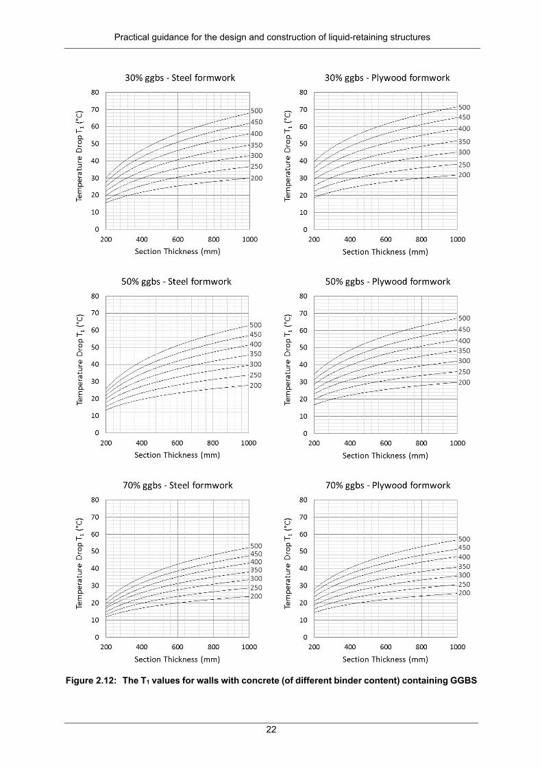
Practical guidance for the design and construction of liquid-retaining structures
22
Figure 2.12: The T1 values for walls with concrete (of different binder content) containing GGBS

Practical guidance for the design and construction of liquid-retaining structures
23
Figure 2.13: The T1 values for walls with concrete (of different strength classes) containing GGBS

Practical guidance for the design and construction of liquid-retaining structures
24
Figure 2.14: The T1 values for walls with concrete (of different binder content) containing fly ash

Practical guidance for the design and construction of liquid-retaining structures
25
Figure 2.15 : The T1 values for walls with concrete (of different strength classes) containing fly ash
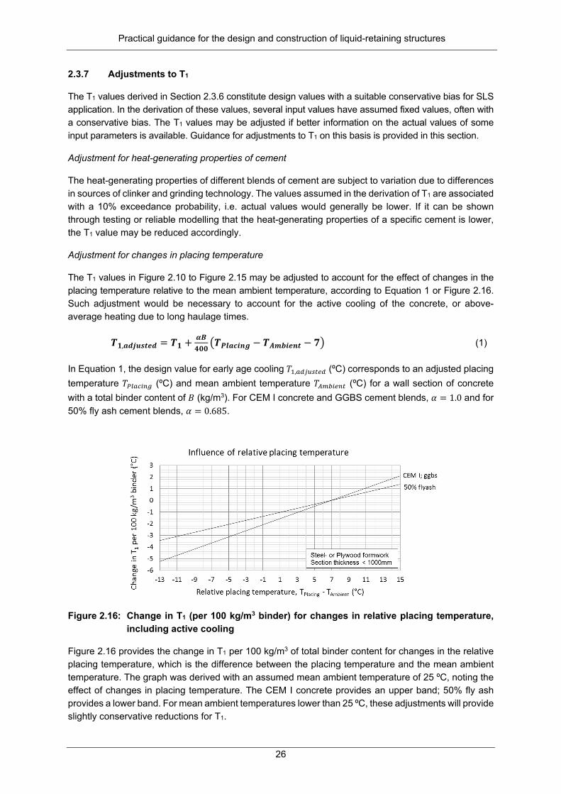
Practical guidance for the design and construction of liquid-retaining structures
26
2.3.7 Adjustments to T1
The T1 values derived in Section 2.3.6 constitute design values with a suitable conservative bias for SLS application. In the derivation of these values, several input values have assumed fixed values, often with a conservative bias. The T1 values may be adjusted if better information on the actual values of some input parameters is available. Guidance for adjustments to T1 on this basis is provided in this section.
Adjustment for heat-generating properties of cement
The heat-generating properties of different blends of cement are subject to variation due to differences in sources of clinker and grinding technology. The values assumed in the derivation of T1 are associated with a 10% exceedance probability, i.e. actual values would generally be lower. If it can be shown through testing or reliable modelling that the heat-generating properties of a specific cement is lower, the T1 value may be reduced accordingly.
Adjustment for changes in placing temperature
The T1 values in Figure 2.10 to Figure 2.15 may be adjusted to account for the effect of changes in the placing temperature relative to the mean ambient temperature, according to Equation 1 or Figure 2.16. Such adjustment would be necessary to account for the active cooling of the concrete, or above-average heating due to long haulage times.
𝑻𝑻𝟏𝟏,𝒂𝒂𝒂𝒂𝒂𝒂𝒂𝒂𝒂𝒂𝒂𝒂𝒂𝒂𝒂𝒂 = 𝑻𝑻𝟏𝟏 + 𝜶𝜶𝜶𝜶𝟒𝟒𝟒𝟒𝟒𝟒
�𝑻𝑻𝑷𝑷𝑷𝑷𝒂𝒂𝑷𝑷𝑷𝑷𝑷𝑷𝑷𝑷 − 𝑻𝑻𝑨𝑨𝑨𝑨𝑨𝑨𝑷𝑷𝒂𝒂𝑷𝑷𝒂𝒂 − 𝟕𝟕� (1)
In Equation 1, the design value for early age cooling 𝑇𝑇1,𝑎𝑎𝑎𝑎𝑎𝑎𝑎𝑎𝑎𝑎𝑎𝑎𝑎𝑎𝑎𝑎 (ºC) corresponds to an adjusted placing temperature 𝑇𝑇𝑃𝑃𝑃𝑃𝑎𝑎𝑃𝑃𝑃𝑃𝑃𝑃𝑃𝑃 (ºC) and mean ambient temperature 𝑇𝑇𝐴𝐴𝐴𝐴𝐴𝐴𝑃𝑃𝑎𝑎𝑃𝑃𝑎𝑎 (ºC) for a wall section of concrete with a total binder content of 𝐵𝐵 (kg/m3). For CEM I concrete and GGBS cement blends, 𝛼𝛼 = 1.0 and for 50% fly ash cement blends, 𝛼𝛼 = 0.685.
Figure 2.16: Change in T1 (per 100 kg/m3 binder) for changes in relative placing temperature,
including active cooling
Figure 2.16 provides the change in T1 per 100 kg/m3 of total binder content for changes in the relative placing temperature, which is the difference between the placing temperature and the mean ambient temperature. The graph was derived with an assumed mean ambient temperature of 25 ºC, noting the effect of changes in placing temperature. The CEM I concrete provides an upper band; 50% fly ash provides a lower band. For mean ambient temperatures lower than 25 ºC, these adjustments will provide slightly conservative reductions for T1.

Practical guidance for the design and construction of liquid-retaining structures
27
Adjustment for different wind speed
Figure 2.17 provides guidance on the influence of wind speed on T1 for different section thicknesses and as a function of total binder content. These values are relevant for CEM I concrete and steel formwork, i.e. these provide upper limits to the influence of wind speed on T1. For 50% fly ash concrete, this adjustment may be halved. When timber formwork is used, the influence of wind is negligible.
Figure 2.17: Change in T1 (per 100 kg/m3 CEM I) for changes in wind speed
Thermal conductivity
Thermal conductivity of concrete is influenced by the mix design, in particular the choice of aggregate and sand. Figure 2.18 provides guidance on adjustments to be made to T1 to account for different values of thermal conductivity. The adjustment was derived for CEM I concrete in steel formwork, providing an upper range of influence.
Figure 2.18: Change in T1 (per 100 kg/m3 CEM I) for changes in thermal conductivity

Practical guidance for the design and construction of liquid-retaining structures
28
Mean ambient temperature
The mean ambient temperature may be expected to differ from the assumed 25 ºC depending on geographical location or if the casting season may be specified. Figure 2.19 shows that such an alternative mean ambient temperature has a relatively mild effect on the T1 design value. An upper bound approximation of its influence is provided by the CEM I sections in steel formwork (solid lines) and a lower bound by the 50% fly ash concrete in plywood formwork (dashed lines). It is assumed that the placing temperature is +7 ºC above the mean ambient temperature.
Figure 2.19: Change in T1 (per 100 kg/m3 binder) for changes in mean ambient temperature
Ground slabs
The T1 values derived in Section 2.3.6 are applicable to walls, where heat will be dissipated similarly from two faces. A ground slab typically has an exposed top surface, with soil providing a fair amount of insulation to the bottom surface. Bamforth (2007) suggests that, for ground slabs less than 500 mm thick, T1 values may be based on the value for a wall of thickness 1.3 times that of the slab, in steel formwork for slabs of which the top surface is exposed, or in timber formwork when insulation is applied.
2.4 TEMPERATURE DIFFERENTIALS ∆T
The heat flow model that was used in Section 2.3.2 to derive T1 values also allows estimation of temperature differentials between the section centre and its surface.
Temperature differentials may cause surface cracking when the surface cools and contracts faster than the centre of the section that acts as an internal restraint. For thick sections, this effect may be quite severe. Although the surface cracks tend to close again on cooling, they will have adverse durability implications. Temperature differentials can be reduced by increasing the isolation provided by the formwork, but bear in mind that this will tend to increase the T1. Careful consideration should be given to these contradicting needs, since T1 contractions in the presence of external restraint may give rise to through cracks, which is potentially more detrimental to the SLS performance of liquid-retaining structures than surface cracks.
In addition to formwork choice, several other factors could increase temperature differentials, such as increased section thickness, early striking times and large diurnal temperature variation.

Practical guidance for the design and construction of liquid-retaining structures
29
The tables below provide estimations of temperature differentials ∆T (ºC), which may be expected in walls with steel (Table 2.7) or plywood formwork (Table 2.8), for a range of section thicknesses and binder contents. The CEM I provides an indication of an upper limit and a 50% fly ash cement blend of a lower limit. Other input parameters have been assumed to be fixed at the values summarised in Table 2.5 in Section 2.3.4.
Table 2.7: Temperature differentials (ºC) for walls in steel formwork
Section thickness (mm)
Total binder content (kg/m3) CEM I 50% fly ash cement blend
300 400 500 300 400 500 300 9 12 14 6 8 9 500 17 22 27 12 14 17 700 24 30 37 16 19 23 1,000 30 38 46 19 24 28
Table 2.8: Temperature differentials (ºC) for walls in plywood formwork
Section thickness (mm)
Total binder content (kg/m3) CEM I 50% fly ash cement blend
300 400 500 300 400 500 300 6 8 9 4 5 6 500 11 14 17 7 9 10 700 15 19 23 10 12 14 1,000 22 28 34 16 19 23
From the tables, it is clear that cement replacement, reduction of binder content and the use of plywood formwork provide efficient recourse to reduce large temperature differentials. Cement replacement and a reduction of binder content would provide the additional benefit of also reducing T1.
2.5 DEVELOPMENT OF T2 DESIGN VALUES
2.5.1 Introduction
Since crack control of liquid-retaining structures are influenced by thermal effects, seasonal variations in environmental temperature need to be characterised for the South African climate for use in design. Due to the diverse South African climate, suitable guidance on the geographic distribution of the seasonal variation of mean ambient temperature is needed for proper design. The T2 is the temperature reduction from the mean ambient temperature at the time of construction to the minimum mean ambient temperature. This depends on the climate at the location of construction, as well as the season in which construction takes place. Summer construction represents the critical case, for which the largest seasonal variation through the summer-winter cycle is expected. Where seasonal variation leads to cracking, this typically becomes apparent within the first summer-winter cycle (NRMCA, 2009).
The two elements of the representation of the seasonal temperature variation are the specification of T2 and how this value can be obtained across the country. In the specification of T2, the mechanism of long-term thermal cracking and the reliability implications of the design procedure need to be considered. This specification then provides the basis for extracting T2 values from South African climate records.

Practical guidance for the design and construction of liquid-retaining structures
30
Although the climate of the UK, on which the CIRIA C660 guidance on T2 is based, is not applicable to South African conditions, it nevertheless provides useful guidance on how to determine appropriate values for T2. The UK seasonal range of mean monthly temperatures of 12 °C is based on a summer mean of 16 °C and a winter mean of 4 °C. However, recommended values for T2 are not based on the seasonal range, but rather on estimated ambient temperatures of 20 °C and 10 °C for summer and winter casting, respectively, allowing for a long-term minimum of 0 °C, discounting the need to provide for prolonged sub-zero temperatures. The resulting recommended values for T2 are therefore given as 20 °C and 10 °C for casting in summer and winter, respectively.
These UK recommendations are simply based on the difference between initial ambient temperature and an estimated minimum. The summer ambient temperature is taken at 4 °C above the monthly mean. The winter ambient temperature is taken at 6 °C above the winter mean, and the minimum is taken at 4 °C below the winter mean temperature. No provision is made for geographical differences in climate conditions. The recommended T2 values are based on a simplified envelope, which should therefore be conservative, but without explicit provision made for reliability of crack width design. The use of ambient temperatures higher and lower than the respective means for the initial and final conditions indicates that provision is made for a time response less than the monthly averages, although T2 is defined to provide for seasonal effects.
For South Africa, equivalent estimates of T2 should provide for a wide range of climatic conditions, in addition to reflecting seasonal temperature changes that are sufficiently reliable, but not overly conservative, yet straightforward to be used in operational design. This would require the use of suitable geographical zoning, quantifying seasonal temperature changes and relating seasonal averages to highest and lowest ambient temperatures to estimate the temperature change of T2 for each zone and casting season. If design for thermally induced cracking is dominated by the effects of T1, the challenge to be precise in estimating T2 is less demanding.
2.5.2 Available climatic data
Characterisation of the South African surface temperature climate for the purpose of deriving recommended values for T2 is primarily based on SAWS data (Kruger, 2008). As an important attribute of climate, surface temperatures reflect climatic conditions ranging from temperate continental conditions across the central plateau, subtropical along the east coast to semi-arid towards the west, with a Mediterranean winter rainfall in the far southwest. Moderate temperatures occur along the extended coastline and adjacent interior, which are influenced by the warm Agulhas current on the east coast and the cold Benguela current on the west coast. Lower temperatures are experienced at high elevations of the escarpment between the coastal terrace and the inland plateau. Temperatures for locations from east to west across the country indicate seasonal values. Differences from the east coast, escarpment, inland and west coast are shown in Table 2.9. Mean temperature changes, comparing the hottest and coldest months, range from 3.6 to 15.3 °C, slightly moderated when the summer (December, January and February) and winter (June, July and August) temperatures are compared. This range confirms the need to account for T2 differences across the country.
Table 2.9: Indicative seasonal temperatures across central South Africa (adapted from Kruger, 2008), shown as the highest monthly or seasonal three-month averages
Month/season Durban Escarp Bloemfontein Port Nolloth Summer (December, January, February)
24.6 / 24.1 °C 18.6 / 18.1 °C 23.0 / 22.2 °C 16.6 / 16.4 °C

Practical guidance for the design and construction of liquid-retaining structures
31
Winter (June, July, August)
16.6 / 17.0 °C 7.1 / 8.1 °C 7.7 / 8.6 °C 13.0 / 13.4 °C
Difference 8.0 / 7.1 °C 11.5 / 10.0 °C 15.3 / 13.6 °C 3.6 / 3.0 °C Mean annual surface temperatures, as mapped by Kruger (2008), range between 15 and 22.5° C when extremes are excluded, while the range of 15 to 20 °C covers more than three-quarters of the country. More important than this surprisingly low range of the representative mean temperature is the close relationship between elevation (see Figure 2.20) and mean temperatures. The dominant influence of elevation can also be observed for seasonal average temperatures (see above). The net effect is that seasonal temperature ranges have a much more regular and smoothed out geographical distribution than the underlying seasonal averages. This is demonstrated by the map of the annual range of the mean monthly temperatures (ΔTm) shown in Figure 2.21 (Kruger, 2008). The main features of the map of ΔTm are values below 7.5 °C along the coastline, increasing regularly up the slope of the escarp towards the inland plateau where it varies between 10 and 12.5 °C across the northern provinces and around 15 °C across the central provinces. This regular pattern suggests the use of ΔTm as a sound basis for the geographical representation of the T2 values.
Figure 2.20: General topography of South Africa (GeoCommunity, 2016)

Practical guidance for the design and construction of liquid-retaining structures
32
Figure 2.21: Annual range of mean monthly temperature ΔTm (°C) (Kruger, 2008)
The variability of ΔTm can be estimated from the standard deviation of the mean seasonal averages. Durban and Upington are used to represent the regions where values of ΔTm vary approximately by a factor of 2 (Kruger, 2016). The close correspondence of the seasonable variability for the two locations that are representative of widely different climates gives confidence that the similarities of the standard deviation for ΔTm are not incidental, concluding that a value of 0.9 °C can be taken to be reasonable for all regions.
Table 2.10: Standard deviation of ΔTm (°C) based on representative seasonal values (Kruger, 2016)
Season Durban Upington Summer (December, January, February) 0.54 °C 0.48 °C Winter (June, July, August) 0.77 °C 0.72 °C Seasonal range 0.94 °C 0.87 °C
2.5.3 Derivation of T2 design values
The basis for the derivation of T2 design values are the following:
• The annual range of the mean monthly average temperature ΔTm serves as the primary input for deriving T2. This deviates from the CIRIA approach, based on mean ambient and estimated minimum temperatures.
• Geographic distribution of T2 is based on zones derived from the ΔTm map, consisting of three zones, where upper limit values are conservatively used: - Zone I: The coastal strip below 200 m elevation, taking ΔTm as 8 °C - Zone II: The northern and balance of the coastal provinces, taking the mean of ΔTm as 12 °C - Zone III: The central-west provinces (Free State and Northern Cape1), taking ΔTm as 16 °C
• ΔTm values are adjusted by +2 °C to derive reliable estimates of more than 1.5 standard deviations above the mean.
• An ambient temperature of +4 °C above the mean monthly casting temperature is implied by CIRIA and is also assumed here.
• The long-term minimum mean monthly temperature (Tm,min) is used as basis for the critical minimum ambient temperature. The slow process of reaching thermal equilibrium may not be sufficiently conservative for slender wall sections to take Tm,min as the critical minimum ambient value (Ta,min). A reduction of 5 °C is applied to obtain Ta,min = Tm,min -5 °C. (The CIRIA-implied value is -4 °C.)
• When the construction season can be specified and controlled, values for T2 may be adjusted to provide for the nominal provision of 10 °C for all zones for winter casting based on ΔTm = 0 °C; for autumn and spring, T2 values may be based on ΔTm values at about half the annual values.
The values recommended for T2 are listed in Table 2.11 for the three zones and possible adjustments for the casting season. The values are similar to the CIRIA recommendations of 20 °C for summer casting and 10 °C for winter casting, save for Zone III where larger seasonal temperature variation dominates. While the values are less than typical provisions for T1 (see previous chapter), it should be noted that the long-term design is based on their combined effect.
1 The Kagisano/Molopo district in the west of North West province may be included here.

Practical guidance for the design and construction of liquid-retaining structures
33

Practical guidance for the design and construction of liquid-retaining structures
34
Table 2.11: Values for T2 based on geographic zones and construction season
Construction season Zone I Zone II Zone III Initial ambient above Tm,max 4 °C 4 °C 4 °C ΔTm (best estimate) 8 °C 12 °C 16 °C Reliability adjustment to ΔTm 2 °C 2 °C 2 °C Critical minimum (Ta,min) below monthly mean minimum (Tm,min)
5 °C 5 °C 5 °C
Unspecified/summer 19 °C 23 °C 27 °C Spring/autumn 14 °C 16 °C 18 °C Winter (nominal value) 10 °C 10 °C 10 °C
2.6 CONCLUSIONS
Geometric design and reinforcement requirements for reinforced concrete reservoirs are generally governed by considerations of the SLS. The predicted crack widths due to thermal contraction is directly related to the temperature reductions quantified respectively by T1 for early-age and T2 for seasonal variation.
Guidance on T1 and T2 design values for South Africa was lacking and is addressed by this report. While CIRIA C660 (Bamforth, 2007) provides guidance on these values for the UK, it was clear that significant adjustments would be required to account for differences in the concretes and climate of South Africa compared to the UK.
2.6.1 Design values for the early-age temperature drop T1
The T1 is the early-age temperature drop from the peak heat of hydration to mean ambient temperature. The amount, types and proportions of binder content determine the heat-generating capacity of the concrete. The section thickness, formwork type, concrete mix proportions, aggregate type and wind speed determine the rate of heat dissipation from the surface of the element, affecting the rate of heat loss and thus the peak heat of hydration. The ambient temperature and placing temperature are additional important parameters.
Several numerical models are available in the literature for the prediction of early-age temperature rise and the subsequent cooling of concrete sections. The model of Bamforth (2007) was chosen to allow easy adjustment of input parameters to account for South African conditions and because predictions match measured results for a wide range of temperatures and concretes.
A basic sensitivity study allowed a ranking of the input parameters in order of descending influence on T1. The input parameters that influence T1 most are those that have to do with heat generation, i.e. the total binder content, types and proportions of binder and specific heat of the concrete mix, in addition to design variables such as section thickness and formwork type.
Consideration of available literature on material test data and South African climate records made it possible to derive mean values and ranges of possible input values for each parameter.
Ultimate heat output and early heat rise values for different binder types, and the specific heat of the concrete, were chosen conservatively. These constitute variables that have a significant influence on the predicted T1, but are not easily controlled by the designer. Conservative bias was broadly based on the target reliability for the SLS under consideration, although full reliability calibration was not attempted. Other input parameters, such as the difference between the mean ambient and placing temperature (which influences early heat rise), wet density, wind speed and diurnal range, were assumed at or close to expected values. This implies that the derived T1 values are suitably conservative, but not overly so.
Practical guidance for the design and construction of liquid-retaining structures
35
The use of conservative bias, or even the use of expected values in the case of parameters that may vary geographically, implies that better information on the actual values of some input parameters may motivate adjustments to the derived T1 values. Guidance on such possible adjustments to T1 are provided for relative placing temperature, wind speed, thermal conductivity, ambient temperature and ground slabs.
Where thermal cracking is critical, the design team is advised to establish T1 (as well as the coefficient of thermal contraction) through testing of the specific concrete mix specified for the project. However, for routine design situations, the graphs presented in this report provide a useful guide.
It was shown that appropriate specifications of design variables such as section thickness, binder content, cement replacement and formwork type would allow efficient control of the temperature rise in most concrete sections. Active cooling to reduce the relative placing temperature was shown to be a further effective measure.
Compared to T1 values derived by Bamforth (2007) for the UK, the South African values are higher by between 1 and 14 ºC, with the largest difference noted for thin sections with a high binder content of CEM I concrete in steel formwork.
2.6.2 Design values for temperature differential ∆T
Design values were also derived for the early-age temperature differential ∆T between the centre of a section and its surface. Although this was not a primary aim of the work, the model that was used to derive T1 values also calculates the temperature differential. Values are provided for walls with steel or plywood formwork for a range of section thicknesses and binder contents.
2.6.3 Design values for seasonal temperature drop T2
The T2 is the temperature reduction from the mean ambient temperature at the time of construction to the minimum mean ambient temperature. This depends on the climate at the location of construction, as well as the season in which construction takes place. Summer construction represents the critical case, for which the largest seasonal variation through the summer-winter cycle is realised.
Careful consideration of South African climate data, including the annual range of mean monthly temperatures and standard deviation of these, allowed the identification of three geographical regions with similar characteristics in terms of seasonal temperature variation. A suitable reliability margin for the limit state under consideration was added based on the standard deviation of the annual range of mean monthly temperatures. Nominal allowances were made for ambient temperatures slightly above the mean at casting and for ambient temperatures below the mean in winter. On this basis, suitable design values for T2 were derived for three geographic zones with possible adjustment for the casting season. Depending on geographical location, T2 values range between 19 and 27 °C for summer casting and 10 °C for winter casting.
2.7 RECOMMENDATIONS
A working group of industry experts and academics was formed in 2013 under SABS Technical Committee 98-02 to develop a local standard using EN 1992-3 and BS 8007 as a reference base. The Working Group identified the lack of suitable design values for thermal cooling (T1 and T2) as an item requiring further research. In the interim, the Working Group included the provisions of CIRIA C660 (Bamforth, 2007) in the draft standard SANS 10100-3: Design of concrete liquid retaining structures. The SABS is in the process of finalising the draft standard for distribution for public comment.
This report developed design values for T1 and T2 that are suitable for use in South Africa. These results should be used to update SANS 10100-3 as soon as possible, preferably before it is distributed for public comment.

Practical guidance for the design and construction of liquid-retaining structures
36
CHAPTER 3: DESIGN GUIDE WITH EXAMPLE CALCULATIONS
3.1 INTRODUCTION
The draft standard SANS 10100-3: Design of concrete liquid-retaining structures used EN 1992-3 and BS 8007 as a reference base. The standard is not meant to be used in isolation. It extends the scope of SANS 51992-1-1 (adopted EN 1992-1-1: Design of concrete structures) and should be used with SANS 10160-1: Basis of structural design. This chapter provides guidance for the analysis of typical liquid-retaining structures with worked design examples for design against load-induced and restraint cracking.
3.2 LIQUID-RETAINING STRUCTURES
3.2.1 General considerations
Liquid-retaining structures are defined as concrete structures that should retain or exclude liquid. These structures are generally either circular or rectangular. Hydrostatic load may result in cracking due to direct tension, flexure or a combination of direct tension and flexure, depending on the type of structural element under consideration. Hydrostatic load is considered to be a quasi-permanent load as emptying and filling of the structure is controlled so as not to induce additional secondary unwanted effects in the structure. Under SLS conditions, the partial load factor for the hydrostatic load is 1.0.
The SLS of cracking generally dominates the design of liquid-retaining structures. The crack width is limited to 0.2 mm for severe or very severe exposure conditions, or 0.1 mm for critical aesthetic appearance. A certain reinforcement configuration is required in the section under consideration, such that the design crack width does not exceed the crack width limit. The compatibility equation for crack width is the product of the crack spacing and the mean strain (i.e. strain at the level considered less the strain due to the stiffening effect of the concrete between the cracks). The design crack width equation used in SANS 10100-3 (Draft) is the empirical formulation of BS 8007:1987, while the equations used to determine tension stiffening for flexure and tension, respectively, are dependent on the specified limiting crack width. We propose that the Working Group consider updating the prediction model for crack widths in line with the findings of Chapter 6 of this report, but provide design guidance here according to the current draft formulation.
The ultimate limit states of bending and shear are also checked in accordance with SANS 51992-1-1, SANS 10100-3 or BS 8110. Shear forces induced at the base of a wall are checked to ensure an adequate section thickness. However, shear is usually not a dominant action effect. The chosen section thickness should be such that shear reinforcement is not required in the wall.
3.2.2 Rectangular tanks
The walls of rectangular tanks generally have to be designed for the following under hydrostatic load:
• In the vertical direction: vertical bending moment, with the wall normally fixed at the base, and at the top free, pinned (i.e. laterally supported by a roof slab) or fixed (i.e. to a roof slab)
• In the horizontal direction: a combination of direct tension and flexure (bending moment) • Shear in combination with direct tension at the corners
Similarly, the floor slabs of rectangular tanks generally have to be designed for the following:
• A combination of direct tension and flexure (bending moment)
Two loading conditions have to be considered:
• Tank filled with liquid, with no soil on the outside • Tank empty, with soil (and ground water) pressure on the outside

Practical guidance for the design and construction of liquid-retaining structures
37
3.2.3 Circular tanks
The walls of circular tanks are usually free at the top. At the bottom, any of the following conditions can exist:
• Wall sliding on the base: This is normally only used in reservoirs with post-tensioned walls, which normally exceed a capacity of 7 to 8 Mℓ
• Wall pinned to the base: This method has fallen in disfavour and is not recommended due to possible waterproofing difficulties at the hinge in the wall (where cracking has to occur)
• Wall fixed to the base: This is generally used in reservoirs with a capacity less than approximately 8 Mℓ
The walls of circular tanks generally have to be designed for the following under hydrostatic load:
• In the circumferential direction: hoop tension • In the vertical direction: vertical flexure (bending moment)
The magnitude and distribution of the hoop tension and vertical moment depend on the aspect ratio of the reservoir and the restraint condition at the bottom of the wall.
A circular tank with a sliding joint at the base behaves as a thin-walled cylinder. The hoop tension in the circumferential direction at any fluid depth, 𝑦𝑦, is therefore:
ryT wγ=
where =wγ unit weight of the fluid
=r internal radius of the wall
=y the depth of the fluid at the position considered
Walls that are pinned or fixed at the base have a distribution of ring tension over the height of the wall as shown in Figure 3.1a. The hoop tension is zero at the base of the wall for both fixity conditions. The hydrostatic load on the wall also induces a vertical bending moment due to the restraint of the wall on the base. The profile of this vertical bending moment depends on whether the wall base is fixed or pinned, as shown in Figure 3.1b. The equations for hoop tension and vertical bending moment are derived from the radial displacement, x, at a depth, y, from the top of the fluid (normally at the top of the wall), i.e.:
yEtr
x w2γ
=
where =wγ unit weight of the fluid
=r internal radius of the wall
=E Young's modulus for the concrete in the wall
=t thickness of the wall
=y the depth of the fluid at the position considered

Practical guidance for the design and construction of liquid-retaining structures
38
Differentiating with regard to y, the equations for hoop tension and vertical bending moment respectively are:
xrEtT =
2
2
dyxdEIM −=
)2
3
1(12 ν−=
tI , where ν is Poisson's ratio for concrete
(a) Ring tension (b) Vertical bending moment
Figure 3.1: Distribution of ring tension and vertical bending moment over the height of the wall
Ring tension and bending moment in the wall are dependent on the ratio rt
h2
2
, where h is the depth of
the fluid. Coefficients to determine ring tension and vertical bending moment can be obtained from tables (Portland Cement Association, n.d.) for different restraint conditions at the bottom of the wall, or these can be determined from a finite element analysis.
3.3 MINIMUM AND THERMAL REINFORCEMENT
3.3.1 Theory (BS 8007 APP A/SANS 10100-3 7.3.4(2) and APPS L and M)
Minimum reinforcement
To be effective in distributing cracking, the minimum amount of reinforcement provided needs to be at least that given by the following equation:
y
ctcrit f
f=ρ (2)
where bhAs
crit =ρ , the ratio of steel to gross area of the concrete section
7,012,0 cuct ff = , the direct tensile strength of the concrete at three days
=yf yield stress of reinforcement

Practical guidance for the design and construction of liquid-retaining structures
39
Thermal and moisture effects
The effective strain, ε, due to thermal effects and shrinkage, can be expressed with the following formulae:
610.100 −−+= tecs εεε (3)
where =csε shrinkage strain
=teε the estimated total thermal contraction after peak temperature
arising from thermal effects
( )21 TTRte += αε (4)
=α coefficient of thermal expansion of mature concrete
=R restraint factor, usually taken as 0.5 (see BS 8007 Figure A3 and
Table A3/SANS 10100-3 Figure L1 and Table L1)
With sufficient reinforcement, the likely maximum crack spacing is:
ρφ2max
b
ct
ffs = , (5)
where =b
ct
ff
ratio of tensile strength of concrete to average bond stress
=ϕ diameter of reinforcement
=ρ ratio of reinforcement based on the areas of the surface zones (BS 8007 Figure A1 and A2/SANS 10100-3 Figure M1 and M2)
Furthermore, the maximum crack width is:
εmaxmax sw = (6)
Substitution of Equation 5 in Equation 6 yields:
ερφ2max
b
ct
ffw = (7)
Rearranging:
max2 wff
b
ctϕερ = (8)

Practical guidance for the design and construction of liquid-retaining structures
40
3.3.2 Example
The wall of a reservoir, which is fixed to the wall footing, is 300 mm thick. There are no vertical joints in the wall and the total length of the wall is more than 15 m. The concrete strength is 40 MPa/19 mm, T1 = 24 °C, T2 = 15 °C, fy = 450 MPa, α = 11.10-6 and εcs = 200.10-6. The design crack width is 0.2 mm.
a) Determine the spacing of Y10, Y12 and Y16 bars in the horizontal direction to satisfy minimum reinforcement requirements.
b) Determine the spacing of Y10, Y12 and Y16 bars in the horizontal direction for thermal and shrinkage effects.
Solutions:
a) Minimum reinforcement:
y
ctcrit f
f=ρ
MPaff cuct 59,140.12,012,0 7,07,0 ===
310.533,3450
59,1 −==critρ
Consider a strip 1,000 mm wide:
bhA crits ρ=
= 3,533.10-3.1000.300
= 1,060 mm2/m width
= 530 mm2/face
b) Reinforcement for thermal effects and shrinkage
( )21 TTRte += αε
= 0,5.11.10-6.(24+15)
=214,5.10-6
610.100 −−+= tecs εεε
=200.10-6+214,5.10-6-100.10-6
=314,5.10-6
67,0=b
ct
ff
BS 8007 Table A1/SANS 10300-3 7.3.4 (2)

Practical guidance for the design and construction of liquid-retaining structures
41
ϕϕϕερ 66
max
10.5272,0.2
10.5,314.67,02
−−
===wf
fb
ct
ϕϕ 1,158300.1000.10.527 6 == −sA
Per face: ϕ1,792=sA
Table 3.1: Summary of reinforcement
φ Minimum reinforcement Reinforcement for thermal effects Spacing Configuration
2sA
Spacing Configuration
10 150 Y10 at 150 HOR EF 791 100 Y10 at 100 HOR EF 12 215 Y12 at 215 HOR EF 949 120 Y12 at 120 HOR EF 16 380 Y16 at 380 HOR EF 1,266 160 Y16 at 160 HOR EF
HOR: Horizontal; EF: External face
Reinforcement for thermal effects dictates and is the minimum that should be provided.
3.4 CALCULATION OF CRACK WIDTHS DUE TO FLEXURE
3.4.1 Theory (BS 8007 APP B/SANS 10100-3 7.3.4(1))
The limit state of cracking is satisfied by ensuring that the maximum calculated surface width of cracks is not greater than the specified value, depending on the degree of exposure of the member. The surface crack width is calculated according to the following procedure:
• Calculate the service bending moment • Calculate the depth of the neutral axis, lever arm and steel stress by the elastic theory • Calculate the surface strain allowing for the tension stiffening effect of the concrete • Calculate the crack width
The maximum service bending moment is calculated using characteristic loads with γf = 1,0. The calculation for a slab or wall is based on a unit width of 1 m.
Figure 3.2: Assumed stress and strain diagram for cracked section, elastic design

Practical guidance for the design and construction of liquid-retaining structures
42
The depth of the neutral axis, x, is calculated using the usual assumptions for modular ratio design (elastic design) of the cracked section. Generally, the compression steel may be ignored in the calculation, since it reduces the crack width slightly.
hhdx
ee
−
+= 121
21
ραρα (9)
bhAs=ρ (10)
eff
se E
E=α (11)
28,21
ceff EE = (12)
Note: The reinforcement ratio and the depth of the neutral axis are expressed in terms of the overall depth of the section, h, and not in terms of the effective depth, d, as customary. The equations above yield the same value for x.
Values of the static modulus of elasticity at 28 days and modular ratio for concrete are given in Table 3.2, as obtained from BS 8110 Part 2.
Table 3.2: Value of static modulus of elasticity of concrete and modular ratio
fcu Ec,28 αe
25 25 16.0 30 26 15.4 35 27 14.8 40 28 14.3
The lever arm z is:
3xdz −= (13)
The lever arm is subject to two restrictions:
dz 95,0≤ and dz65
≥
The first restriction is to allow for the concrete at the surface of the compression zone not being well compacted, and the second restriction is to limit the neutral axis depth to 0.5 d to prevent the crushing of the concrete in bending.
The tensile steel and concrete compressive stresses are then as follows:
s
ss zA
Mf = (14)
zbxMf s
cb2
= (15)

Practical guidance for the design and construction of liquid-retaining structures
43
For the crack width formula to be valid, the compressive stress in the concrete and the tensile stress in the steel under service conditions must be less than the limiting values as follows:
cucb ff 45,0≤
ys ff 8,0≤
If these criteria are met, the formulae for crack width calculation may be used. The average strain at the level where cracking is considered (εm) is assessed by calculating the apparent strain at the level considered (ε1), which is adjusted to take account of the stiffening effect of the concrete between cracks (ε2) (see Figure 3.2).
21 εεε −=m (16)
( )( ) s
s
Exdfxh
−−
=1ε (17)
The formulae for the stiffening effect of the concrete between cracks include an assumed value of strain and therefore can only be used for particular values of design crack width. The stiffening effect of the concrete may be assessed by deducting from the apparent strain a value obtained from the appropriate equation below.
For a limiting design surface crack width of 0.2 mm:
( )( )
)(3'
2 xdAExaxhb
ss
t
−−−
=ε (18)
For a limiting design surface crack width of 0.1 mm:
( )( )
)(3'5,1
2 xdAExaxhb
ss
t
−−−
=ε (19)
The value a’ in these formulae is the distance from the compression face of the section to the point at which the crack width is being calculated. In the case of a slab, a’ is equal to the overall depth, h. The maximum width of a surface crack in a slab is along a line midway between two adjacent bars.
The design surface crack width, w, is obtained from the formula that is stated in BS 8007/SANS 10300-3 and acr is the maximum distance between the concrete surface and the surface of the nearest bar as shown in Figure 3.3. A negative calculated value of w indicates that the section is uncracked.
−−
+=
xhca
awcr
mcr
min21
3 ε (20)

Practical guidance for the design and construction of liquid-retaining structures
44
The symbols used are summarised below:
ε1 is the strain at the level considered, ignoring the stiffening effect of the concrete in the tension zone
εm is the average strain at the level at which cracking is being considered, allowing for the stiffening effect of the concrete in the tension zone
a’ is the distance between the compression face and the point at which the crack width is being calculated
acr is the distance between the point considered and the surface of the nearest longitudinal bar (see Figure 3.3)
As is the area of steel
bt is the width of the section at the centroid of the tension steel
cmin is the minimum cover over the tension steel
d is the effective depth of the member
Es is the modulus of elasticity for steel
Ec,28 is the static modulus of elasticity for concrete at 28 days
fs is the service stress in the reinforcement
h is the overall depth of the member
x is the depth of the neutral axis
Figure 3.3: Definition of 𝒂𝒂𝑷𝑷𝒄𝒄
3.4.2 Example
Check whether the design crack width for a wall, 300 mm overall thickness, reinforced with Y12 at 150 c/c EF, minimum cover = 40 mm, concrete strength = 30 MPa/19 mm, and applied service moment of 47 kNm/m, is within 0.2 mm width.

Practical guidance for the design and construction of liquid-retaining structures
45
Solution mmmAs /754 2=
mmd 254640300 =−−=
002513,0300.1000
754===
bhAsρ
GPaEs 200= and GPaEc 2628, =
GPaEeff 13226
==
GPae 4,1513200
==α
Depth of neutral axis (ignore compression steel):
hhdx
ee
−
+= 121
21
ραρα
mm663001300254
002513,0.4,1521002513,0.4,15
21
=
−
+=
mmxdz 2323
662543
=−=−=
( )
=>>= mmdzmmd 7,211
653,24195,0 , OK
MPafMPazAMf y
s
ss 3608,07,268
754.23210.47 6
=<=== , OK
MPafMPazbxMf cu
scb 5,1345,014,6
66.1000.23210.47.22 6
=<=== , OK
( )( ) 0016722,0
10.2007,268
)66254()66300(
31 =−−
=−−
=s
s
Exdfxh
ε
( )( ) ( )( ) 0006438,0
)66254(754.10.200.366300663001000
)(3'
32 =−−−
=−−−
=xdAExaxhb
ss
tε
0010284,00006438,0001672,021 =−=−= εεεm
mmcsacr 98,812
122
12402
150222
2222
=−
++
=−
++
=
ϕϕ

Practical guidance for the design and construction of liquid-retaining structures
46
mmmm
xhca
awcr
mcr 20,0186,0
663004098,8121
0010284,0.98,81.3
21
3min
<=
−−
+=
−−
+=
ε
3.5 CALCULATION OF CRACK WIDTHS DUE TO TENSION
3.5.1 Theory (BS 8007 APP B/SANS 10100-3 7.3.4(1))
Pure tensile forces occur in the circumferential direction in circular reservoirs. A crack due to tensile forces is of greater significance as a crack due to flexure as the crack penetrates the full depth of the section, and is therefore more likely to allow leakage to occur. The calculation of crack widths due to direct tension is similar to that caused by flexure in that the apparent surface strain is calculated and modified for the stiffening effect due to the concrete between the cracks.
Figure 3.4: Section under direct tension, assumed stress and strain diagram
The average strain at the surface of the section, εm, is:
221 εεεε −=−=s
sm E
f (21)
The stiffening effect of the concrete, ε2, is as follows:
For a limiting design surface crack width of 0.2 mm:
ss
t
AEhb
32
2 =ε (22)
For a limiting design surface crack width of 0.1 mm:
ss
t
AEhb
=2ε (22)
The design surface crack width is:

Practical guidance for the design and construction of liquid-retaining structures
47
mcraw ε3= (23)
Note: The abovementioned equations are only valid when the reinforcement and cover in both faces are the same.
3.5.2 Example
Check whether the design crack width for a wall, 250 mm overall thickness, reinforced with Y12 at 125 c/c EF, minimum cover = 40 mm, concrete strength = 30 MPa/19 mm, and an applied service direct tensile force of 500 kN/m width, is within 0.2 mm.
Solution: mmmAs /1810905.2 2==
MPaATf
ss 3,276
181010.500 3
===
6
31 10.138110.2003,276 −===
s
s
Ef
ε
6
32 10.4,4601810.10.200.3
250.1000.232 −===
ss
t
AEhb
ε
6
21 10.6,920 −=−= εεεm
mmcsacr 6,712
122
12402
125222
2222
=−
++
=−
++
=
ϕϕ
mmaw mcr 198,010.6,920.6,71.33 61 === −ε
3.6 CALCULATION OF CRACK WIDTHS FOR COMBINED FLEXURE AND DIRECT TENSION
Neither BS 8007 nor SANS 10100-3 provides guidelines for the calculation of design surface crack widths due to combined flexure and direct tension. Since combined flexure and direct tension often exist in structural elements of water-retaining structures (e.g. in the horizontal direction of walls of rectangular or square tanks), a need for calculating design crack widths for this case exists. The calculation procedure is cumbersome, and articles by Kruger (2012) and Kruger and Atkinson (2005) propose a rational method for calculating design crack widths at the two faces of a section under these loadings. The proposed method can also be used for a section under direct tension where the reinforcement configuration and concrete cover in the two faces differ. More information about these articles, including errata, are provided on www.hgk.co.za. The restrictions on lever arm depth shown in Section 3.3 do not apply to this case.
3.7 DESIGN OF CIRCULAR RESERVOIR WALL FOR DIFFERENT RESTRAINT CONDITIONS
Compare the design of the wall of a reservoir with an inner diameter of 20 m and a wall height of 5 m for the following three restraint conditions:
• Wall sliding on the base • Wall pinned to the base • Wall fixed to the base

Practical guidance for the design and construction of liquid-retaining structures
48
Other design parameters are as follows:
fcu = 35 MPa/19 mm Use αe = 15 c = 40 mm γw = 9,81 kN/m3
fy = 450 MPa Es = 200 GPa wmax = 0.2 mm H = 250 mm
3.7.1 Wall sliding on base
There are no vertical bending moments in a wall sliding on a base, and the only force in the wall is the hoop tension acting in the circumferential direction.
Horizontal reinforcement assumed at the bottom of the wall:
Y12 at 125 HOR EF (As = 905 mm2/m/face = 1,810 mm2/m total)
Maximum hoop tension at the bottom of the wall is (SLS, with γf = 1,0):
mkNrHT ws /5,4905.10.81,9 === γ
MPafMPaAT
f ys
ss 5,39187,0271
181010.5,490 3
=<===
0013550,010.200.1810
10.5,4903
3
1 ===ss
s
EAT
ε
0004604,01810.10.200.3
250.1000.232
32 ===ss
t
AEhb
ε
0008946,021 =−= εεε m
mmcsacr 6,712
122
12402
125222
2222
=−
++
=−
++
=
ϕϕ
mmmmaw mcr 20,0192,010.6,894.6,71.33 61 <=== −ε
3.7.2 Wall pinned to base
Horizontal reinforcement assumed at position of maximum hoop tension:
Y12 at 175 HOR EF IL (As = 646 mm2/m/face=1,292 mm2/m total)
Vertical reinforcement assumed at position of maximum positive moment:
Y12 at 250 VER OF OL (As = 452 mm2/m) (VER = Vertical; OF = Outer face; OL = Outer layer)
The maximum serviceability hoop tension and vertical bending moment are calculated using tables for the given reservoir dimensions and wall base fixity conditions to obtain the coefficients αn1 and αm1.
mkNmHrT wns /6,30210.5.81,9.617,01 === γα
Practical guidance for the design and construction of liquid-retaining structures
49
mkNmHM wms /5,115.81,9.0094,0 331 === γα

Practical guidance for the design and construction of liquid-retaining structures
50
Horizontal design
MPafMPaAT
f ys
ss 5,39187,02,234
129210.6,302 3
=<===
001171,010.200.1292
10.6,3023
3
1 ===ss
s
EAT
ε
0006450,01292.10.200.3
250.1000.232
32 ===ss
t
AEhb
ε
0005261,021 =−= εεε m
mmc 521240 =+= (since horizontal bars are located IL)
mmcsacr 0,992
122
12522
175222
2222
=−
++
=−
++
=
ϕϕ
mmmmaw mcr 20,0156,010.1,526.0,99.33 61 <=== −ε
Vertical design
mmd 204640250 =−−=
001808,0250.1000
452===
bhAsρ
hhdx
ee
−
+= 121
21
ραρα
mm3,462501250204
001808,0.1521001808,0.15
21
=
−
+=
mmxdz 6,1883
3,462043
=−=−=
( )
=>>= mmdzmmd 0,170
658,19395,0 , OK
MPafMPazAM
f ys
ss 3608,09,134
452.6,18810.5,11 6
=<=== , OK
MPafMPazbxM
f cus
cb 5,1345,063,23,46.1000.6,188
10.5,11.22 6
=<=== , OK
( )( ) 0008712,0
10.2009,134
)3,46204()3,46250(
31 =−−
=−−
=s
s
Exdfxh
ε

Practical guidance for the design and construction of liquid-retaining structures
51
( )( ) ( )( ) 0009702,0
)3,46204(452.10.200.33,462503,462501000
)(3'
32 =−−−
=−−−
=xdAExaxhb
ss
tε
000099,00009702,00008712,021 −=−=−= εεε m
mmcsacr 2,1272
122
12402
250222
2222
=−
++
=−
++
=
ϕϕ
mmmm
xhca
aw
cr
mcr 20,0020,0
3,46250402,12721
)0000994,0.(2,127.3
21
3
min
<−=
−−
+
−=
−−
+=
ε
The section is uncracked under bending moment, and nominal reinforcement for thermal effects are required.
3.7.3 Wall fixed to base
Horizontal reinforcement assumed at position of maximum hoop tension:
Y10 at 150 HOR EF IL (As = 524 mm2/m/face = 1,048 mm2/m total)
Vertical reinforcement assumed at position of maximum negative moment at the bottom of the wall:
Y12 at 200 VER OF OL (As = 565 mm2/m)
The maximum serviceability hoop tension and positive and negative vertical bending moments are calculated using tables for the given reservoir dimensions and wall base fixity conditions to obtain the coefficients αn1, αm1 and -αm1.
mkNmHrT wns /0,23410.5.81,9.477,01 === γα
Positive moment: mkNmHM wms /2,75.81,9.0059,0 331 === γα
Negative moment: mkNmHM wms /2,275.81,9.0222,0 331 −=−== γα
Horizontal design
MPafMPaAT
f ys
ss 5,39187,03,223
104810.0,234 3
=<===
0011164,010.200.1048
10.0,2343
3
1 ===ss
s
EAT
ε
0007952,01048.10.200.3
250.1000.232
32 ===ss
t
AEhb
ε
0003212,021 =−= εεε m

Practical guidance for the design and construction of liquid-retaining structures
52
mmc 521240 =+= (since horizontal bars are located IL)
mmcsacr 2,892
102
10522
150222
2222
=−
++
=−
++
=
ϕϕ
mmmmaw mcr 20,0086,010.25,321.2,89.33 61 <=== −ε
Vertical design mmd 204640250 =−−=
002260,0250.1000
565===
bhAsρ
hhdx
ee
−
+= 121
21
ραρα
mm9,502501250204
00226,0.152100226,0.15
21
=
−
+=
mmxdz 0,1873
9,502043
=−=−=
( )
=>>= mmdzmmd 170
658,19395,0 , OK
MPafMPazAM
f ys
ss 3608,04,257
565.0,18710.2,27 6
=<=== , OK
MPafMPazbxM
f cus
cb 5,1345,072,59,50.1000.0,187
10.2,27.22 6
=<=== , OK
( )( ) 001674,0
10.2004,257
)9,50204()9,50250(
31 =−−
=−−
=s
s
Exdfxh
ε
( )( ) ( )( ) 00007638,0
)9,50204(565.10.200.39,502509,502501000
)(3'
32 =−−−
=−−−
=xdAExaxhb
ss
tε
0009099,021 =−= εεε m
mmcsacr 1,1042
122
12402
200222
2222
=−
++
=−
++
=
ϕϕ
mmmm
xhca
aw
cr
mcr 20,0173,0
9,50250401,10421
0009099,0.1,104.3
21
3
min
<=
−−
+=
−−
+=
ε
From inspection, nominal reinforcement required for thermal effects would be sufficient for the positive

Practical guidance for the design and construction of liquid-retaining structures
53
bending moment.
3.7.4 Comparison of three restraint options
Considering the same wall cross-section, Table 3.3 demonstrates the influence of the wall fixity on the serviceability design for cracking. Ring tension is substantially greater in the case of a sliding wall than for fixed and pinned walls, requiring a greater area of reinforcement.
Table 3.3: Effect of wall restraint
Parameter Restraint condition of wall Free sliding Pinned Fixed
Horizontal reinforcement Y12 at 125 Y12 at 175 Y10 at 150 Vertical reinforcement Y12 at 250 Y12 at 200
Ts [kN/m] 490,5 302,6 235,0 Ms+ [kNm/m] - 11,5 7,2 Ms- [kNm/m] - - -27,2 w for Ts [mm] 0,192 0,156 0,086
w for Ms+ [mm] - -0,020 -0,061 w for Ms- [mm] - - 0,173
The purpose of this example is only to show the effect of the restraint condition at the bottom of the wall on ring tension and vertical bending moments. Therefore, reinforcement for thermal effects have not been determined. The wall thickness for the pinned and fixed cases could probably be reduced. The notes in Section 3.2.3 pertaining to the practicality of restraint conditions should also be considered.
3.8 INFLUENCE OF SOIL-STRUCTURE INTERACTION ON CIRCULAR RESERVOIR WALL FORCES
The forces and moments in the wall of a circular reservoir are influenced by the following:
• The restraint conditions at the bottom of the wall: - Wall sliding on wall footing (usually used in post-tensioned concrete reservoir walls) - Wall pinned to wall footing (not used often) - Wall fixed to wall footing (generally used in reinforced concrete reservoir walls), and in this
case, whether the wall footing can slide or not • The stiffness of the foundation material underneath the reservoir
Various finite element analyses on a typical 6 Mℓ reservoir with the wall fixed to the wall footing were performed to investigate the influence of the abovementioned on the forces and moments in the wall and wall footing. Due to symmetry, an eighth of the reservoir was modelled as shown in Figure 3.5..
The characteristics of the model are as follows:
• The floor slab, wall footing, wall and roof slab have been modelled with plate elements • The soil underneath and on the side of the reservoir have been modelled with brick elements • The columns supporting the roof slab have been modelled with beam elements • Compression-only contact elements have been modelled between the floor slab and wall footing
and the soil • Compression-only contact elements have been modelled between the wall and the roof slab to
simulate a sliding bearing

Practical guidance for the design and construction of liquid-retaining structures
54
Two structural configurations have been investigated:
• Configuration 1: Wall footing monolithic with floor slab, i.e. radial outward movement of the wall footing is restrained by the floor slab
• Configuration 2: Joint between wall footing and floor slab, i.e. the wall footing can slide radially outwards.
Two different founding materials have been investigated:
• Medium hard rock, E = 5,000 MPa and ν = 0.2 • Very dense, stiff soil, E = 90 MPa and ν = 0.35
The density of the water has been taken as 10 kN/m3, and the water depth has been taken as the full height of the wall.
The theoretical forces and moments in the wall for different restraint conditions are shown in Table 3.4. The results from the finite element analyses are shown in Table 4.5.
Figure 3.5: Finite element model of 6 Mℓ reservoir

Practical guidance for the design and construction of liquid-retaining structures
55
Table 3.4: Theoretical forces and moments in reservoir wall
Parameter Wall restraint conditions Fully fixed Pinned
Negative vertical moment at footing, M-ver -76.7 kNm/m 0 Positive vertical moment, M+ver 19.8 kNm/m 30.6 kNm/m Circumferential tension, Thor 738.8 kN/m 899.6 kN/m
Table 4.5: Results from FE analyses on reservoir
Configuration Element Parameter Founding material Medium
hard rock Very dense,
stiff soil
Wall footing monolithic with floor
slab
Wall M-ver [kNm/m] -61.9 (81%) -71.0 (93%) M+ver [kNm/m] 17.4 (88%) 17.0 (86%)
Thor [kN/m] 772.2 (105%) 761.4 (103%)
Wall footing Thor [kN/m] 145.0 154.5
Radial movement [mm] 0.22 0.23
Joint between wall footing and floor
slab
Wall M-ver [kNm/m] -42.2 (55%) -43.2 (55%) M+ver [kNm/m] 13.0 (66%) 13.0 (66%)
Thor [kN/m] 797.2 (108%) 796.3 (108%)
Wall footing Thor [kN/m] 686.6 691.2
Radial movement [mm] 1.12 1.12
Note: Percentages in brackets show the percentage of the value in relation to the theoretical value for the fixed case.
From the finite element analyses for the configuration with the wall footing being monolithic with the floor slab, the following can be concluded:
• The forces in the wall are influenced by the stiffness of the soil. • The stiffer the soil, the lower the vertical moment at the bottom of the wall, and the higher the value
of the circumferential tension in the wall. The vertical moments are less than the theoretical values, and the circumferential forces are higher than the theoretical values.
• Circumferential tension also exists in the wall footing. This is due to the elastic radial restraint offered by the floor slab, which allows the footing to move out radially by only 0.2 mm. Generally, nominal thermal reinforcement should be sufficient to ensure compliance with crack width requirements.
From the finite element analyses for the configuration where there is a joint between the wall footing and the floor slab, the following can be concluded:
• There is very little variance in the moments and circumferential tension in the wall with varying stiffness of the soil, albeit that the vertical moment at the footing is reduced to only 55% of the theoretical and the circumferential force increased to 108% of the theoretical.
• The abovementioned is caused by a radial outward movement of the wall footing of only 1 mm more than for the configuration where the wall footing is monolithic with the floor slab (i.e. where the floor slab restrains the movement of the wall footing).
• Large circumferential tension also exists in the wall footing. It is approximately 86% of the value in the wall. Nominal thermal reinforcement would generally not be sufficient to ensure compliance with crack width requirements, and the exact circumferential tension in the footing and reinforcement to ensure compliance with the design crack widths could be determined. It should be borne in mind that the wall footing for the configuration shown forms part of the water-retaining structure and therefore also has to be water-tight.

Practical guidance for the design and construction of liquid-retaining structures
56
The reservoir wall, wall footing and part of the floor slab have also been modelled with axisymmetric elements, with the wall footing and floor slab being supported on an elastic medium, which is modelled with a compression-only subgrade modulus of elasticity. This model yields inaccurate results, and is not recommended. It is difficult to determine the modulus of subgrade reaction. It is dependent on the size of the reservoir, and would be higher on the edge of the reservoir than in the centre (French et al., n.d). With such a model, the effect of the shear strength of the material surrounding the reservoir is also ignored.
The following approach for the design of a circular reservoir with the wall fixed to the wall footing is therefore recommended:
• Unless very accurate information of the soil underneath and outside the footprint of the reservoir is available to great depth (such as from a borehole investigation), modelling of the soil-structure interaction is not recommended. Even if such accurate information is available, the variability of soil properties should be taken into consideration in such analyses.
• Unless radial outward movement of the wall footing is restrained, circumferential tension will exist in the footing. This should be taken into account in the design of the circumferential reinforcement in the wall footing.
• Designing the reservoir wall as follows should prevent crack width problems: - Vertically at the wall footing: design for the full theoretical negative moment for the fully fixed
case - Vertically in the wall above the wall footing: design for the theoretical positive moments for the
pinned case - Horizontally: design for the theoretical circumferential tensile forces for the pinned case
3.9 DESIGN OF THE WALL OF THE CIRCULAR RESERVOIR
Design the wall of the 6 Mℓ reservoir as shown in Figure 3.6 at the position of maximum negative and positive bending moments in the vertical direction, and maximum direct tension in the circumferential direction. The wall will be constructed in rings not exceeding 2.4 m in height. The wall footing is restrained against outward radial movement. Other design parameters are shown in Figure 3.6.
fcu = 30 MPa/19 mm εcs = 200.10-6 γw = 10 kN/m3 Ec = 26 GPa T1 = 24 °C c = 40 mm Es = 200 GPa T2 = 12 °C wmax = 0.2 mm fy = 450 MPa α = 11.10-6/°C
Figure 3.6: Wall of 6 Mℓ reservoir

Practical guidance for the design and construction of liquid-retaining structures
57
3.9.1 Forces and moments
Determine the working forces and moments in the reservoir wall using the theory for a beam on elastic foundation or tables (Portland Cement Association, n.d.):
For tables: 0,825,0.32
822
==dth
Maximum shear force: mkNVs /1118.10.174,0 ==
mkNVu /155111.4,1 ==
Table 3.6: Theoretical vertical moment Ms and horizontal tension Ts
Position from top
Fixed wall Hinged wall Ms
[kNm/m] Ts
[kN/m] Ms
[kNm/m] Ts
[kN/m] 0.0 h 0.0 -14.1 0.0 -19.2 0.1 h 0.0 133.1 0.0 122.9 0.2 h 0.5 279.0 0.0 266.2 0.3 h 1.0 428.8 -1.0 414.7 0.4 h 4.1 567.0 0.0 567.0 0.5 h 8.2 683.5 3.6 721.9 0.6 h 14.3 736.0 10.2 846.1 0.7 h 19.5 678.4 19.5 892.2 0.8 h 14.8 487.7 29.2 794.9 0.9 h -11.3 193.3 27.6 494.1 1.0 h -74.8 0.0 0.0 0.0
3.9.2 Design options
Determine the design options:
There are no vertical joints in the wall, therefore Option 1 of BS 8007 (Table 5.1/SANS 10100-3 Table N1) applies to the horizontal direction.
Due to the fact that the wall is cast in rings not exceeding 2.4 m in height and the fact that there are no vertical free edges, Option 3 of BS 8007 (Table 5.1/SANS 10100-3 Table N1) applies to the vertical direction (see BS 8007 Clause 5.3.3(2)).
3.9.3 Minimum reinforcement
Horizontal direction
The minimum amount of reinforcement required is 𝝆𝝆𝑷𝑷𝒄𝒄𝑷𝑷𝒂𝒂.
MPaff cuct 30,130.12,012,0 7,07,0 ===
310.889,2450
30,1 −==critρ
facemmmAs //3612/250.1000.10.889,2 23 == −

Practical guidance for the design and construction of liquid-retaining structures
58
Vertical direction
The minimum amount of reinforcement required is critρ32 .
However, since it is such a small amount, rather use ρcrit as above.
Y10 at 200 VER EF would satisfy 𝝆𝝆𝑷𝑷𝒄𝒄𝑷𝑷𝒂𝒂.
3.9.4 Reinforcement for thermal and moisture effects
Due to the construction method, thermal and moisture effects only apply to the horizontal direction.
The aspect ratio of the wall is:
8,4428
16..2>==
πHL BS 8007 Figure A3/SANS 10100-3 Figure L1
Therefore, the restraint factor 𝑅𝑅 = 0,5 BS 8007 Table A3/SANS 10100-3 Table L1
( ) 6621 10.198)1224(10.11.5,0 −− =+=+= TTRte αε
66666 10.29810.10010.19810.20010.100 −−−−− =−+=−+= tecs εεε
67,0=b
ct
ff
BS 8007 Table A1/SANS 10100-3 7.3.4(2)
φϕϕερ 6
6
max
10.2,4992,0.2
10.298..67,02
−−
===wf
f
b
ct
Per face: ϕϕ 4,622
250.1000.10.2,499 6
==−
sA
Reinforcement for thermal effects dictates in the horizontal direction.
Table 3.7: Summary of reinforcement in horizontal direction
φ Reinforcement for thermal effects
2sA
Spacing Chosen configuration
10 624 126 Y10 at 125 HOR EF 12 749 151 Y12 at 150 HOR EF 16 998 201 Y16 at 200 HOR EF
3.9.5 Vertical design of wall
Design the wall in the vertical direction for the following in accordance with the recommendations in Section 3.3.8 and place the vertical reinforcement in the outer layers with a cover of 40 mm:
• Negative moment at the bottom for the fixed wall case, i.e. Ms = -74.8 kNm/m • Positive moment for the hinged case, i.e. Ms = 29.2 kNm/m

Practical guidance for the design and construction of liquid-retaining structures
59
Negative moment
mkNmM s /8,74−=
Try Y16 at 100 VER IF OL (VER = Vertical; IF = Inner face; OL = Outer layer)
mmmAs /2011 2=
mmd 202840250 =−−=
008044,0250.1000
2011===
bhAsρ
GPaEs 200=
GPaEeff 13226
==
GPae 4,1513200
==α
Depth of neutral axis:
hhdx
ee
−
+= 121
21
ραρα
mm1,852501250202
008044,0.4,1521008044,0.4,15
21
=
−
+=
mmxdz 6,1733
1,852023
=−=−=
( )
=>>= mmdzmmd 3,168
659,19195,0 , OK
MPafMPazAMf y
s
ss 3608,03,214
2011.6,17310.8,74 6
=<=== , OK
MPafMPazbxMf cu
scb 5,1345,01,10
1,85.1000.6,17310.8,74.22 6
=<=== , OK
( )( ) 001511,0
10.2003,214
)1,85202()1,85250(
31 =−−
=−−
=s
s
Exdfxh
ε
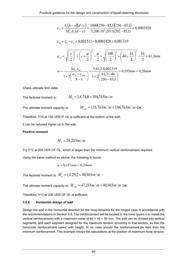
Practical guidance for the design and construction of liquid-retaining structures
60
( )( ) ( )( ) 0001928,0
)1,85202(2011.10.200.31,852501,852501000
)(3'
32 =−−−
=−−−
=xdAExaxhb
ss
tε
001319,00001928,0001511,021 =−=−= εεεm
mmcsacr 3,612
162
16402
100222
2222
=−
++
=−
++
=
ϕϕ
mmmm
xhca
awcr
mcr 20,0193,0
1,85250403,6121
001319,0.3,61.3
21
3min
<=
−−
+=
−−
+=
ε
Check ultimate limit state:
The factored moment is: mkNmM u /7,1048,74.4,1 ==
The ultimate moment capacity is: mkNmmkNmM cap /7,104/7,135 >= OK
Therefore, Y16 at 100 VER IF OL is sufficient at the bottom of the wall.
It can be reduced higher up in the wall.
Positive moment
mkNmM s /2,29=
Try Y12 at 200 VER OF OL, which is larger than the minimum vertical reinforcement required.
Using the same method as above, the following is found:
mmmmw 20,0197,0 <=
The factored moment is: mkNmM u /9,402,29.4,1 ==
The ultimate moment capacity is: mkNmmkNmM cap /9,40/2,47 >= OK
Therefore, Y12 at 200 VER OF OL is sufficient.
3.9.6 Horizontal design of wall
Design the wall in the horizontal direction for the hoop tensions for the hinged case in accordance with the recommendations in Section 3.6. The reinforcement will be located in the inner layers (i.e. inside the vertical reinforcement) with a maximum cover of 40 + 16 = 56 mm. The wall can be divided into vertical segments, and each segment designed for the maximum tension occurring in that section, so that the horizontal reinforcement varies with height. In no case should the reinforcement be less than the minimum reinforcement. This example shows the calculations at the position of maximum hoop tension.

Practical guidance for the design and construction of liquid-retaining structures
61
Maximum hoop tension:
mkNTs /2,892=
Try Y16 at 100 HOR EF
mmmfacemmmAs /4022//2011 22 == total
0011091,010.200.4022
10.2,8923
3
1 ===ss
s
EAT
ε
0002072,04022.10.200.3
250.1000.232
32 ===ss
t
AEhbε
0009020,021 =−= εεεm
mmcsacr 2,732
162
16562
100222
2222
=−
++
=−
++
=
ϕϕ
mmmmaw mcr 20,0198,010.0,902.2,73.33 61 <=== −ε
Check ultimate limit state:
The factored hoop tension is: mkNTu /12492,892.4,1 ==
The ultimate moment capacity is:
mkNmkNmmkNAfT sycap /1249/1575/10.4022.450.87,087,0 3 >=== − OK
Therefore, Y16 at 100 HOR EF IL is sufficient.
3.9.7 Shear
Check shear at the bottom of the wall.
mkNVu /155=
For Y16 at 100 VER IF:
mmmAs /2011 2=
%0,1202.1000
2011.100100==
bdAs
( )MPa
ffdbd
A
v
cu
m
cus
c 80,025,1
302024001
2540010079,0
31
41
313
141
31
=
=
=γ
MPaMPabdVv u 80,077,0
202.100010.155 3
<===
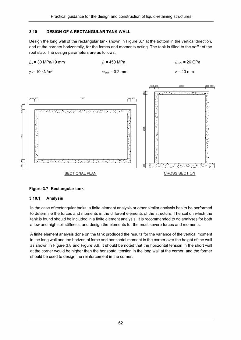
Practical guidance for the design and construction of liquid-retaining structures
62
3.10 DESIGN OF A RECTANGULAR TANK WALL
Design the long wall of the rectangular tank shown in Figure 3.7 at the bottom in the vertical direction, and at the corners horizontally, for the forces and moments acting. The tank is filled to the soffit of the roof slab. The design parameters are as follows:
fcu = 30 MPa/19 mm fy = 450 MPa Ec,28 = 26 GPa
γw= 10 kN/m3 wmax = 0.2 mm c = 40 mm
Figure 3.7: Rectangular tank
3.10.1 Analysis
In the case of rectangular tanks, a finite element analysis or other similar analysis has to be performed to determine the forces and moments in the different elements of the structure. The soil on which the tank is found should be included in a finite element analysis. It is recommended to do analyses for both a low and high soil stiffness, and design the elements for the most severe forces and moments.
A finite element analysis done on the tank produced the results for the variance of the vertical moment in the long wall and the horizontal force and horizontal moment in the corner over the height of the wall as shown in Figure 3.8 and Figure 3.9. It should be noted that the horizontal tension in the short wall at the corner would be higher than the horizontal tension in the long wall at the corner, and the former should be used to design the reinforcement in the corner.
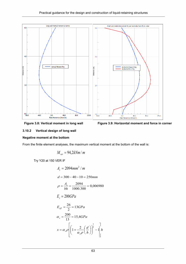
Practical guidance for the design and construction of liquid-retaining structures
63
Figure 3.8: Vertical moment in long wall Figure 3.9: Horizontal moment and force in corner
3.10.2 Vertical design of long wall
Negative moment at the bottom
From the finite element analyses, the maximum vertical moment at the bottom of the wall is:
mkNmM ver /2,94=
Try Y20 at 150 VER IF
mmmAs /2094 2=
mmd 2501040300 =−−=
006980,0300.1000
2094===
bhAsρ
GPaEs 200=
GPaEeff 132
26==
GPae 4,1513200
==α
hhdx
ee
−
+= 121
21
ραρα

Practical guidance for the design and construction of liquid-retaining structures
64
mm7,983001300250
006980,0.4,1521006980,0.4,15
21
=
−
+=
mmxdz 1,2173
7,982503
=−=−=
( )
=>>= mmdzmmd 3,208
655,23795,0 , OK
MPafMPazAMf y
s
ss 3608,02,207
2094.1,21710.2,94 6
=<=== , OK
MPafMPazbxMf cu
scb 5,1345,079,8
7,98.1000.1,21710.2,94.22 6
=<=== , OK
( )( ) 0013777,0
10.2001,207
)7,98250()7,98300(
31 =−−
=−−
=s
s
Exdfxh
ε
( )( ) ( )( ) 0002132,0
)7,98250(2094.10.200.37,983007,983001000
)(3'
32 =−−−
=−−−
=xdAExaxhb
ss
tε
0011646,00002131,00013777,021 =−=−= εεεm
mmcsacr 14,80220
22040
2150
222
2222
=−
++
=−
++
=
ϕϕ
mmmm
xhca
awcr
mcr 20,020,0
7,983004014,8021
0011646,0.14,80.3
21
3min
≤=
−−
+=
−−
+=
ε
Positive moment mid-height in wall
From the finite element analyses, the maximum vertical moment mid-height in the wall is:
mkNmM ver /2,41=
Try Y12 at 150 VER OF
mmmAs /754 2=
mmd 254640300 =−−=
002513,0300.1000
754===
bhAsρ

Practical guidance for the design and construction of liquid-retaining structures
65
Depth of neutral axis (ignore compression steel):
hhdx
ee
−
+= 121
21
ραρα
mm0,663001300254
002513,0.4,1521002513,0.4,15
21
=
−
+=
mmxdz 2323
662543
=−=−=
( )
=>>= mmdzmmd 7,211
653,24195,0 , OK
MPafMPazAMf y
s
ss 3608,05,235
754.23210.2,41 6
=<=== , OK
MPafMPazbxMf cu
scb 5,1345,038,5
66.1000.23210.2,41.22 6
=<=== , OK
( )( ) 001466,0
10.2005,235
)66254()66300(
31 =−−
=−−
=s
s
Exdfxhε
( )( ) ( )( ) 0006438,0
)66254(754.10.200.366300663001000
)(3'
32 =−−−
=−−−
=xdAExaxhb
ss
tε
0008218,00006438,0001466,021 =−=−= εεεm
mmcsacr 0,822
122
12402
150222
2222
=−
++
=−
++
=
ϕϕ
mmmm
xhca
awcr
mcr 20,0149,0
66300408221
0008218,0.82.3
21
3min
≤=
−−
+=
−−
+=
ε
3.10.3 Horizontal design of long wall
From the finite element analysis, the most critical combination of flexure and direct tension in the corner of the tank is:
mkNmM hor /9,56=
mkNmThor /1,91=
Try Y16 at 125 HOR IF IL and Y12 at 125 HOR OF IL

Practical guidance for the design and construction of liquid-retaining structures
66
According to the method described in the specialist literature (Kruger, 2002; Kruger and Atkinson, 2005), the results for some of the parameters for the crack width calculations are as follows:
mmx 9,73=
MPafs 8,1981 =
MPafcb 75,5=
mmmmw 20,0197,01 <=
Note: The minimum and thermal reinforcement for the wall should be determined according to Section 3.3 above for the specific construction method. Where this exceeds the reinforcement required for the forces and moments, this should be provided.
3.11 CONCLUSION
This chapter provided guidance on the analysis of typical liquid-retaining structures, as well as example calculations according to SANS 10100-3 for load-induced and restraint-induced cracking.

Practical guidance for the design and construction of liquid-retaining structures
67
CHAPTER 4: TENDER SPECIFICATIONS FOR LIQUID-RETAINING STRUCTURES
4.1 INTRODUCTION AND SCOPE
All structural concrete has to meet the design requirements of the ultimate and serviceability limit states, including requirements on strength, stability, robustness, durability and deflections. To achieve these, a suitable design must be well executed in construction. A suitable design should conceptually produce a structure that is safe, fit for purpose, economical, practical to construct and easy to maintain. Good construction practice, combined with adequate quality control, should then ensure that these objectives are realised.
Existing documents that detail standard requirements for construction works are readily available in South Africa in the form of the SANS 1200 series, replaced in 2007 by SANS 2100. Structural concrete was addressed by SANS 1200 Part G and is now addressed by SANS 2100 CC1.
Liquid-retaining structures have to meet additional serviceability requirements in terms of durability and leak tightness.
The aim of this chapter is to provide specification data that extends the scope of SANS 2100 CC1 to be generally applicable to the construction of liquid-retaining structures and that can readily be modified to make provision for particular liquid-retaining structure projects. This chapter provides technical descriptions of the standard of materials and workmanship that shall be used in the works or in the evaluation of the performance of the works when executed. The design and supervision of the works shall be under the direct control of appropriately qualified engineers and technologists.
Neither SANS 2100 nor this report deals with the measurement of works for the purpose of payment. For this, reference should be made to the South African edition of Civil Engineering Standard Method of Measurement (CESMM) or to Clause 8 of SANS 1200. Reference is also not made to the parties to a contract or their respective contractual responsibilities. As such, the specification is suitable to use in all types of engineering contracts.
It is foreseen that this contribution may be helpful to small or even medium-sized engineering consultancy firms where in-house experience, specifically with liquid-retaining structures, may be limited.
In drafting this generic specification a wide range of literature, including international standards, technical guidelines, handbooks and articles were consulted, which were further informed by discussion with and comment from various South African industry experts as acknowledged.
4.2 STANDARD SPECIFICATIONS
Existing documents that detail standard requirements for construction works are readily available in South Africa in the form of the SANS 1200 series, recently replaced by SANS 2100. Structural concrete is covered by Part G of SANS 1200 and by Part CC1 of SANS 2100. Addendum B of this report provides a cursory comparison of the technical content of SANS 1200 G as opposed to SANS 2100 CC1.
4.2.1 SANS 1200
The SANS 1200 standard was developed by the South African Institute of Civil Engineers (SAICE) in the 1970s for use in tenders compiled for the design by employer contracting strategy. This standard has become significantly outdated; firstly due to significant changes in materials since the 1980s, secondly because subjectivity was introduced through master-servant type of phrasing, and thirdly because it was developed around a single contracting strategy (Watermeyer et al., 2012; Watermeyer, 2016).

Practical guidance for the design and construction of liquid-retaining structures
68
The SABS officially withdrew SANS 1200 in 2007 when the SANS 2100 series was published. Despite its withdrawal, SANS 1200 is still widely used in industry. Its continued use may be due to an initial lack of an alternative system of measurement to the system embedded in Clause 8 of SANS 1200. The Southern African edition of the CESMM has since been published to meet this need.
This system, or the one embedded in Clause 8 of SANS 1200, may be used with any specifications of the works, irrespective of contracting strategy. See Watermeyer (2016) for specific wording to call up either of the two standard systems of measurement, both of which are independent of specifications.
4.2.2 SANS 2100
The SANS 2100 standard was developed on the basis of input by the Joint Structural Division of SAICE, the Institution of Structural Engineers and the Cement and Concrete Institute, and published by SABS in 2007. Different parts of SANS 2100 address a specific component of construction works and provide technical descriptions of the standard of materials and workmanship that shall be used in the works or in the evaluation of the performance of the works when executed. Objective phrasing of specifications is achieved by making no mention of the parties to the contract or those responsible for the execution of the works. The series is also suitable for any type of engineering and construction works contract.
Procurement documents comprise a number of component documents, one of which would be the “scope of work”. The SANS 2100 provides generic specifications as a basis for the scope of work and may be modified for a specific project or purpose by specification data in the scope of work. Specification data would contain essential data, for example as required by Table A2 of SANS 2100 CC1, as well as optional variations and additional clauses as needed.
4.3 SPECIFICATION FOR A GENERIC LIQUID-RETAINING STRUCTURE
4.3.1 Requirements for liquid-retaining concrete structures
The SANS 2100 CC1 makes adequate provision for the construction of general structural concrete. Liquid-retaining structures have additional requirements pertaining to durability and liquid tightness.
Liquid-retaining structures are usually operated in aggressive environments where wetting and drying cycles are common and/or structures are in contact with sewage, sea water or ground water. For this reason, concrete durability needs special attention. Durability considerations include the provision of concretes and grouts with sufficient density, compaction and chemical properties to withstand aggressive environments for the lifetime of the structure, the provision of adequate cover to reinforcement, as well as the prevention of alkali-silica reaction2 and plastic shrinkage cracking. Due care is required with regard to compaction, curing and protection, especially when placing concrete during adverse weather. Achieved durability should be tested against specified indices.
Liquid-retaining structures are further required to contain or exclude liquids and, as such, these structures must be liquid tight. Here, the construction and movement joints, including details of waterstops and sealants, require special attention, since these are prone to leak. In addition, crack widths need to be controlled for cracking due to load- or restraint-induced actions. Penetrations should not induce restraint, should be watertight and should allow adequate local compaction. Underfloor drainage should allow the detection of floor leaks. Finally, provision should be made for testing liquid tightness and related acceptance criteria.
2 A moist environment is typical for liquid-retaining structures, which increases the risk of alkali-silica reaction.

Practical guidance for the design and construction of liquid-retaining structures
69
4.3.2 Guide to specification data
Provided in this report as Appendix A is specification data to facilitate the implementation of good construction practice for most types of liquid-retaining structures. Additional specifications mainly pertain to ensuring liquid tightness and meeting more stringent durability requirements for the aggressive environments within which these structures often operate, as discussed in Section 4.3.1, Table 4.1 summarises the main additional requirements and provides references to clause numbers in the specification data (Addendum A) where essential data, variations or additions address the relevant construction aspect. Table 4.1: Breakdown of additional requirements for liquid-retaining structures and related
clause references to provisions in the specification data provided in Addendum A
Requirement Clauses of essential data Variations Additions
Durability
Prevent alkali-silica reaction through proper mix design and testing.
4.2.1.1; 4.2.3.1; 4.2.3.5; 4.7.1.1; 5.1.1.8
- -
Ensure adequate compaction of concrete, particularly at joints, around waterstops, in areas of dense reinforcement and at penetrations.
4.7.2.1 - 4.7.10.18; 4.7.11.9 to 12
Concrete mix design and constituents to ensure durability, including adequate density, workability, admixtures and testing.
4.2.1.1; 4.2.3.1; 4.2.4; 4.2.6; 4.7.1.1; 5.1.3.2
4.2.1.3; 4.2.3.3 4.7.14.8
Ensure adequate protection and curing, including for adverse weather concreting.
4.7.13.8; 4.7.14.7 4.7.14.1 4.7.13.8; 4.7.14.7
Durability index specification - - 4.7.5.3; 4.7.5.4
Grout requirements 4.2.7; 5.1.4.4 - -
Durability of steelwork, pipework or other fittings
4.2.11.4; 4.5.1
Other - 4.4.2.3 -
Liquid tightness
Construction joints – requirements for joint preparation and positions.
4.7.12.1.1; 4.7.12.1.4
- 4.7.12.2.4
Movement joints – requirements for joint forming, waterstops, joint fillers and sealants.
- - 4.6.2.3; 4.7.12.2.5 to 8

Practical guidance for the design and construction of liquid-retaining structures
70
Requirement Clauses of essential data Variations Additions Waterstops, joint fillers and sealants – material and installation requirements.
4.2.11; 4.6.2.1 4.2.11.1 to 7 4.7.12.4.1 to 6
Control of crack widths – reinforcement detailing, cover tolerances, reducing restraint action from shrinkage and heat of hydration, including concrete mix design considerations.
4.2.1.1; 4.2.3.5; 4.2.6; 4.3.5.3; 4.7.1.1; 5.1.6.8; 5.2.1.1; 4.7.14.8
4.2.3.6d; 4.4.3.2; 4.7.14.1
5.6.1.8; 4.7.1.1; 4.7.14.8
Fittings and penetrations – preventing restraint, ensuring adequate local compaction and liquid tight seals.
- 4.3.3.2 4.3.3.6
Repair of cracks, defects and ferrule holes – methods and grout requirements.
4.2.7; 4.7.19.6 and 7
4.3.3.3; 5.1.6.3 4.7.19.6; 4.7.19.7
Liquid-tightness tests 5.1.6 - 5.1.6.4 to 7
Underfloor drainage - - 4.7.8.4.7
Formwork requirements - 4.3.5 4.3.3.6; 4.7.14.8
Other
Cleaning and disinfection of potable water-retaining structures
4.9.2.1.1 - 5.1.6.9 to 11
Tolerances - 5.2.8 -
4.4 CONCLUSION
The standard specification SANS 2100 CC1 for structural concrete was extended to provide for liquid-retaining structures. For this purpose, Annexure A provides the specification data, variations and additional clauses to include for a generic liquid-retaining structure, noting considerations where project-specific provision should be made.

Practical guidance for the design and construction of liquid-retaining structures
71
CHAPTER 5: CONSTRUCTION GUIDELINES FOR LIQUID-RETAINING STRUCTURES
5.1 SCOPE AND INTRODUCTION
This guideline gives methods to specify, produce and assess concrete structures for liquid-retaining purposes.
All concrete structures have to meet design requirements in terms of strength, stability, robustness and serviceability. Liquid-retaining structures have to meet additional requirements in terms of durability and leak tightness. This guideline focuses on construction practices that are required to achieve these additional requirements. It is primarily intended for site personnel.
Design engineers should take note of the recommendations regarding construction methods, since the constructability of the structure and its various components and details have to be considered at the design stage. Design engineers should furthermore ensure that tender specifications provide for appropriate construction practice.
A first draft of this guideline was included as an informative annexure to SANS 10100-3. It is updated here based on input from industry experts and consideration of related literature. This guideline excludes provisions for pre-stressed and pre-cast construction, for which the reader is referred to the standard of the American Concrete Institute (ACI), ACI 373R-97: Design and construction of circular prestressed concrete structures with circumferential tendons, where extensive guidance is provided, both for design and construction.
Design guidance is provided in SANS 10100-3. However, Section 5.13 provides some additional design considerations. It is recommended that these be considered for inclusion in SANS 10100-3 at its next revision.
5.2 ADMINISTRATION
5.2.1 Site personnel
All key site personnel from all parties involved should preferably have previous experience in the construction of liquid-retaining structures. Required levels of experience of the contractor’s site personnel should be specified in the contract documentation. As a minimum requirement, the following is advised: The main agent on site should have five to 10 years’ experience, including involvement in the construction of at least three types of liquid-retaining structures (in terms of shape, size or reinforcing type). The main agent should be deemed to be the highest-ranking contractor’s agent permanently on site. At least a third of the foremen should have experience of the construction of at least five liquid-retaining structures.
All key site personnel involved in the construction of liquid-retaining structures should be briefed on the design objectives. The differences between general concrete structures and water-retaining concrete structures should be highlighted at the start of the project during the construction project brief.
5.2.2 Construction project brief
A proposed agenda for the construction project brief could be as follows:
a) Introduction of key personnel b) Establishing and defining the roles and responsibilities c) Establishing communication channels

Practical guidance for the design and construction of liquid-retaining structures
72
d) Introduction to the project, including a wider background of the project and the client’s objectives e) Introduction to various structures and other elements of the project f) Project programme; supply information g) Concrete for liquid-retaining structures, durability and leak tightness h) Concrete mixes, including cement pastes, aggregates, water, admixtures i) Testing of concrete: cube strength, slumps, absorption, oxygen permeability, chloride conductivity
(coastal environments) j) Curing method k) Repair of concrete: honeycombing, cracks, construction joints, ferrule holes, concrete delamination l) Testing of other materials and products: structural steel, coating on structural steel, anchor bolts,
compaction of backfill m) Placing and details of reinforcement, stools, clips, concrete spacers, concrete cover to
reinforcement n) Site reinforcement for emergency situations, cutting and bending o) Construction sequence, location and details of construction joints, actual forming of construction joints p) Water tightness tests, including planning q) Sterilisation of the structure r) Loading of structures, temporary loads or construction loads, age of structure at loading s) Quality control
5.2.3 Quality control
The project specifications for liquid-retaining structures are likely to include more stringent requirements than for many other reinforced concrete structures due to their uniquely different loadings, more severe exposure conditions and more restrictive serviceability requirements.
Most contractors have their standard quality control documentation. It is important that specified requirements pertaining to liquid-retaining structures are included in such documentation. All specified requirements should be controlled by testing or inspection. Examples include stringent curing provisions, the testing of durability indexes, slump, bandage adhesion and grout performance.
5.3 LOADINGS
5.3.1 Construction loads
In most cases, a structure is designed for the loadings pertaining to its working life. Construction loads are typically temporary in nature. They sometimes exceed the design loads. Before placing high construction loads on a structure, it should be confirmed that adequate structural capacity is available to carry such loads. Some examples of construction loads are the following:
• Excess loading of stone or earth on a roof of reservoir • One-sided loading to a baffle wall • Backfilling to a partially completed structure • Mobile crane on the floor of a reservoir • Any loading at early age, i.e. before concrete is 28 days old
5.3.2 Permanent loadings
The most important permanent load for a liquid-retaining structure is the load of the liquid. The design liquid level for tanks should always be shown on the design drawings. This level should not be exceeded, most notably during water tightness testing. The emergency overflow outlets from liquid-retaining structures should therefore always be open and unobstructed.

Practical guidance for the design and construction of liquid-retaining structures
73
5.4 CONCRETE
5.4.1 General
Concrete for liquid-retaining structures has to satisfy additional requirements in terms of durability and leak tightness. Such additional requirements can be met by changes to the concrete mix design, special cements to be used, the inclusion of additives to the mix, as well as enhanced placing and compaction techniques. The necessity of obtaining dense, well-compacted concrete, free of honeycombing and cold joints, cannot be overemphasised, according to ACI 373R-97: Design and construction of circular prestressed concrete structures with circumferential tendons.
5.4.2 Concrete mix design
Annexure K of SANS 10100-3 makes recommendations on the concrete mix design for liquid-retaining structures. Some excerpts from this annexure are provided here as it pertains to the contractor.
Cements
Only common cements conforming to SANS 50197-1 shall be used.
Cement extenders
Only the following Portland cement extenders conforming to SANS 1491 shall be used as an additional extension (normally at the site of concrete mixing) to common cement:
• SANS 1491: Part 1 – ground granulated blast furnace slag • SANS 1491: Part 2 – fly ash • SANS 1491: Part 3 - silica fume
The use of either GGBS or fly ash will be primarily to reduce the maximum heat of hydration temperature attained and thereby reduce the risk of thermal cracking (National Ready Mixed Concrete Association, 2009).
If used, the role of silica fume will primarily be that of a concrete durability enhancer. The use of silica fume will normally be in minor quantities of 0 to 15% cement replacement, with percentages on the high end of this scale requiring specialist knowledge and admixtures to ensure workability. Percentages higher than 5% are not recommended for liquid-retaining structures. In most cases, it will be used in conjunction with either GGBS or fly ash.
Note: Exclusions can be made for other commonly used common cement extenders that do not conform to any current national standard e.g. Corex slag (GGCS). When using GGCS as an additional extension, it is recommended that it is used in conjunction with one or more approved Portland cement extender, i.e. in such a way that both a similar heat of hydration increase and similar maximum heat of hydration temperature are attained, as an equivalent additional GGBS and/or fly ash extension. Note that the use of GGCS as an extender on its own, in most cases, will not reduce the heat of hydration and may even increase it. Further exclusions may be made for accepted inert extenders such as finely ground limestone or similar.
Aggregates
Aggregates to be used should be submitted for testing, according to critical tests identified in SABS 1083. Ideally, the aggregates should comply with these critical tests. It is accepted that, in some cases (only practical aggregate available or aggregates sourced from remote, temporary quarries, borrow pits or rivers), where aggregates do not conform to the limits imposed by critical tests, exceptions can be made where accepted methods may be adopted to overcome the shortcomings.

Practical guidance for the design and construction of liquid-retaining structures
74
Aggregate absorption should generally not be greater than 3%. In the case of an aggregate exceeding an absorption rate of 1.5%, the aggregate shall be treated with potable water in such a way that the aggregate absorption is eliminated, i.e. saturated surface dry state. This is normally effectively achieved by soaking affected aggregate stockpiles with potable water (ensure that soaked stockpiles are adequately drained).
Coarse aggregates with a low coefficient of thermal expansion are preferred (refer to the appropriate chapter on the thermal properties of concrete in Cement and Concrete Institute (2009)).
Water
Water used in the mixing of concrete should ideally be potable. In remote areas where potable water may not be practically available and water is sourced from rivers or boreholes, it must be submitted for testing for suitability for use in concrete (refer to appropriate chapter on mixing water in Cement and Concrete Institute (2009)).
Mix proportions
The rate of heat of hydration increases and the maximum heat of hydration temperature attained must be controlled to reduce the likelihood of thermal cracking. In order to achieve this, for the majority of common cements, an extender should be added (normally at the site of concrete mixing). Suggestions are provided in Table 4.1 of SANS 10100-3 (South African Bureau of Standards, 2015).
The need to meet the requirements of concrete durability test specifications and at the same time minimise the heat of hydration factors should be the determining factors in selecting the type of cement used.
To achieve these mix design objectives, the following is advised:
• Use a water-to-binder ratio applicable to the common cement being used plus any additional extender addition, which will achieve the stipulated 28-day characteristic compressive strength by an appropriate margin of safety (depending on the sophistication of the concrete manufacturer’s controls). The target compressive strength thus achieved should not exceed the 28-day characteristic compressive strength excessively (typically 3 to 6 MPa, 8 MPa maximum is suggested). If this is not controlled, it will negate the objective of minimising the effects of heat of hydration. From a durability perspective, a water-to-binder ratio ≤ 0.55 is recommended.
• A maximum free water content (excluding aggregate absorption water) of 190 ℓ per m3 is recommended. Higher free water content will tend to increase the risk of not meeting the durability testing specifications.
Note: The water-to-binder ratio implies a ratio where the binder can be solely common cement, but more often common cement plus an approved additional common cement extender.
Workability
The workability of the concrete should be specified in relation to the equipment, and methods of handling and compaction, so that the concrete is placed without segregation, fully compacted, surrounding all reinforcement, tendons and ducts, and completely filling the formwork. It is particularly important to ensure that full compaction is obtained in the vicinity of construction and movement joints, embedded water bars, tendon anchorages and pipes.
For standard concrete, it is recommended that a slump between 100 and 120 mm is targeted, while for pump mixes, a slump between 120 and 150 mm is recommended. If self-compacting concrete is used, specialist advice should be sought. Slumps towards the high end of this range should be targeted if extended travelling times are expected to allow for evaporation during transport and to prevent the need to revive workability at the point of discharge.

Practical guidance for the design and construction of liquid-retaining structures
75
Under no circumstances should water be used to revive workability. Where environmental conditions are such and/or concrete transport travel times are significantly extended, workability revival to design workability should only be carried out with an approved workability revival admixture. Workability revival admixtures are normally added to the concrete at the point of discharge immediately prior to discharge. In cases where the aforementioned conditions are experienced, the addition of a retarding admixture at the point of manufacture may be necessary to prevent setting of the concrete during transport.
5.4.3 Compaction
Compaction or vibration of concrete for liquid-retaining structures is identical to ordinary concrete structures. The following improvements can be made:
• After-vibration or revibration: This method can be of importance at the top of walls. The top of the wall (approximately the top 600 mm) can be vibrated again after completing a wall section, thus eliminating any voids that may have formed below horizontal reinforcement bars. Such revibration should be done while the concrete is still in the green state, i.e. the concrete must close the hole where the poker is extracted. The exact timing of such revibration needs to be determined by experimenting and could be in the order of one or two hours after completing a wall section.
• Over-compaction: Fresh concrete against existing concrete, i.e. at construction joints, should be well compacted. In a well-designed concrete mix with the right water-to-cement ratio, the risk of segregation due to over-compaction is remote. It should be noted that most liquid-retaining structures show leakages at construction joints that could have been prevented by some extra compaction effort.
• When pouring in layered passes, the poker should penetrate at least 200 mm into the previously poured layer.
• Compaction at recesses and openings: All recesses and openings in liquid-retaining structures should be detailed in such a way that proper compaction is possible. If detailing is incorrect or insufficient, the contractor should propose alternatives to the design engineer. The following points can be noted:
‐ Box-outs for pipe penetrations through walls should be placed with sides at 45° to the horizontal (in the plane of the wall, i.e. diamond orientation rather than square).
‐ Horizontal recesses should have a 45° slope at the bottom (seen in a section of the wall). ‐ Square permanent openings, if unavoidable, should have casting windows at the bottom.
Alternatively, pipes may be provided through which the poker can be inserted to connect the top of the box-out to its bottom. The pipes are filled with concrete and broken out afterwards. With this alternative, surface repair will be required.
• Where the wall is designed to be monolithic with the base slab, a kicker should not be cast as adequate compaction is difficult to achieve.
5.4.4 High evaporation concreting
Concreting during times of high evaporation is particularly challenging. High evaporation typically occurs during hot weather, high winds and/or dry air. It is the combination of the three mentioned factors that results in high evaporation.
Higher temperatures cause water to evaporate from the surface of the concrete at a rate faster than the bleed rate of concrete, increasing incidences of plastic cracking.

Practical guidance for the design and construction of liquid-retaining structures
76
The evaporation rate should be calculated using the ACI 305R-99 monograph or Equation 24 below.
𝐸𝐸 = 5([𝑇𝑇𝑃𝑃 + 18]2.5 − 𝑟𝑟[𝑇𝑇𝑎𝑎 + 18]2.5)(𝑉𝑉 + 4)10−6 (24)
where
𝐸𝐸 = Evaporation rate, kg/m2/hour
𝑇𝑇𝑃𝑃 = Concrete temperature, °C
𝑇𝑇𝑎𝑎 = Air temperature, °C
𝑟𝑟 = Relative humidity, (RH %)/100
𝑉𝑉 = Wind velocity, kph
Table 5.1 may be useful to estimate surface wind velocity when measurement is not practical. In the absence of specific cooling measures, but with adequate care taken to avoid the adverse heating of constituent materials, concrete placing temperature may be assumed to be 8 °C above the air temperature.
Table 5.1: Estimating wind speed
Estimated surface wind speed, kph Description
< 1 Calm: smoke rises vertically 1–3 Wind direction is shown by smoke drift, but not wind vanes 4–7 Wind is felt on face; leaves rustle 8–12 Leaves and small twigs are in constant motion; wind extends light flag 13–18 Wind raises dust and loose paper; small branches move 19–25 Small trees in leaf begin to sway; crested wavelets form on inland waters 26–32 Large branches in motion; umbrellas are hard to use
The contractor should implement measures to prevent plastic shrinkage cracks if the calculated evaporation rate is more than 0.5 kg/m2 per hour.
Note that concretes with high proportions of fine aggregate or cement replacement of fly ash, slag or silica fume have reduced bleeding rates. For these concretes, plastic shrinkage may prove to be problematic at even lower evaporation rates.
Concreting should ideally not take place in adverse weather conditions. If unavoidable, one or more of the following measures should be taken to mitigate the effects of a high evaporation environment:
• Concreting during early morning hours • Avoiding prolonged mixing of concrete materials • Using site-batching so that concrete is very fresh when placed • Shade storage of aggregates • Cooling (wetting) of aggregate • Using iced water or liquid nitrogen to cool the concrete mix • Using evaporation-retarding admixtures • Avoiding admixtures that reduce bleed rate • Using mist spray on steel formwork • Using shade netting

Practical guidance for the design and construction of liquid-retaining structures
77
• Using wind breaks • Using mist spray at the point of placing (imperative for evaporation rates in excess of 1 kg/m2 per hour • Using appropriate placement techniques and sequences.
The protection of concrete in these conditions is particularly important, refer to Section 5.10.
5.4.5 Hot weather concreting
Concreting in hot weather, with or without high evaporation, increases water demand, the rate of slump loss and the rate of setting. This implies difficulty in handling, placing, compacting and finishing, and higher likelihood of plastic shrinkage cracking.
The risk of through cracking in walls and slabs is also increased as higher concrete placement temperature leads to higher peak hydration temperature rises. Precautions should therefore be taken to ensure that concrete placement temperature does not exceed the theoretical allowance made in the design. The maximum allowable concrete placing temperature should be stated on drawings. Note that this does not refer to the ambient temperature.
Concreting should ideally not take place in adverse weather conditions. If unavoidable, one or more of the following measures should be taken to mitigate the risk of early-age thermal cracking:
• Concreting during early-morning hours • Avoiding prolonged mixing of concrete materials • Shade storage of aggregates • Cooling of aggregate by wetting • Using iced water or liquid nitrogen to cool the concrete mix • Using wet hessian around the water truck • Painting mixers, silos and bins white and/or insulating them • Using mist spray on steel formwork • Using shade netting • Using appropriate placement techniques and sequences to reduce restraint
The peak hydration temperature is typically reached within 30 hours of placement. The use of mist spray on steel formwork and shade netting should thus be continued for approximately 30 hours. For sections thicker than 600 mm, the use of mist spray on steel formwork should be used with caution as surface cooling may lead to surface cracks due to large temperature differentials.
5.4.6 Cold weather concreting
When ambient temperatures are 5° C or lower, the weather is described as “cold”. During cold weather, concreting the cement hydration process occurs more slowly or does not occur at all.
Stripping times for formwork are normally increased in winter, as per SANS 2001-CC1 (Table 2 and clause 4.7.14.2). The best method of curing is to use insulated formwork over a sustained period. All exposed faces should be protected. Water curing methods should not be used during cold weather.
Special measures like the heating of aggregate and/or mixing water are seldom taken in South Africa.
5.4.7 Pneumatically applied mortar
The pneumatic application of mortar (shotcrete) is a specialist operation and should only be carried out by experienced operators. The designer should agree on a full specification with the contractor for materials, mix proportions, mixing, placing, equipment and curing before any work commences. The ACI 373R-97 standard gives guidance for the use of shotcrete to protect externally placed pre-stressing cables.

Practical guidance for the design and construction of liquid-retaining structures
78
5.4.8 Cast-in-place walls
A 25 to 50 mm layer of neat cement grout is recommended at the base of cast-in-place walls to help preclude voids in this critical area. The grout should have about the same water-to-cement ratio as the concrete that is used in the wall, and should have the consistency of thick paint.
Some experts recommend a 600 mm thick layer of concrete with aggregate of a maximum size of 9 mm to be placed at the base of the wall to help preclude voids in congested areas such as around waterstops.
5.5 REINFORCEMENT
5.5.1 Quality control of reinforcement
One of the most vital aspects of overall quality control on site is the quality control of reinforcement. The quality control of reinforcement on site mainly comprises three parts: checking the quality of the reinforcement, checking the quantity of the reinforcement, and checking the placement and the cover of the reinforcement.
• Checking the quality of the reinforcement: This entails checking the mechanical properties of the reinforcement, mostly tensile strength and elongation. All reinforcement must comply with SANS 920. Steel bars are used for concrete reinforcement. Mill certificates for the reinforcement should be obtained at the beginning of the project. In addition, a number of sample bars should be taken for tensile and elongation tests. Such tests should be repeated as per the specification data during the construction phase. If deemed necessary, the chemical properties of the steel can be checked as well. Particular care should be taken with imported products.
• Checking the quantity of the reinforcement: The quantity of reinforcement can easily be evaluated by checking the bar diameters and bar spacing. Equal bar spacing is important since crack widths are influenced by bar spacing.
• Checking the placement and the cover of the reinforcement: The correct placing or positioning of the reinforcement is important, in particular the nominal concrete cover:
‐ If the nominal concrete cover to reinforcement is less than specified, the long-term durability of the structure will be reduced, despite a smaller crack width and an increase in flexural strength for that particular section.
‐ If the nominal concrete cover to reinforcement is more than specified, the crack width will increase, and the flexural strength will decrease.
‐ From the above two measures, it is clear that positive tolerances on cover are as important as negative ones, and that reinforcement should be placed in its designed position.
‐ Concrete spacers (often called cover blocks or spacer blocks) provide the specified nominal cover between the reinforcement nearest to the surface of the concrete element and the surface itself. Only cementitious, proprietary spacers should be used, preferably the circular variety. The concrete grade should be the same as for the structure. Plastic spacers and spacers made on site should never be used. Concrete spacers should be placed at bar intersections and spaced at not less than 50 d, where d is the diameter of the bar that is supported. Concrete spacers should be spaced in staggered rows. Blocks must be wetted before placing the concrete to prevent local dry spots in the concrete.
‐ Concrete spacer blocks should be placed as mentioned above to prevent the reinforcement from getting too close to the surface. They do, however, not prevent the reinforcement from moving away from that surface. This is of particular importance, but not limited to walls with one or two sloping surfaces.

Practical guidance for the design and construction of liquid-retaining structures
79
‐ Ties or clips are used to prevent reinforcement from moving away from wall surfaces. They should be fixed to the inner reinforcement bars, so as not to encroach into the concrete cover. Ties or clips should be spaced at not less than 50 d, where d is the diameter of the bar that is supported. As for concrete spacers, the ties or clips should be spaced in staggered rows. The reinforcement in opposite faces of a wall can also be kept separate by using stools or chairs. These are more efficient than clips at keeping the rebar apart, but come at a slight additional cost and are slightly harder to fix.
‐ Stools or chairs (the word “chair” is used in the British Codes) are mostly used to support the top reinforcement in slabs and floors. The detailing of stools is adequately covered in SANS 0144. The legs of stools should be detailed long enough to be able to rest on and should be fixed to the two bottom bars. Stools should be placed close to concrete spacers and spaced at not less than 50 d, where d is the diameter of the bar that is supported. Stools should be spaced in staggered rows. Stools should stand on the B2 reinforcement layer and support the T2 layer.
‐ The ends of wire ties should not encroach into the concrete cover.
Bending schedules should be reviewed for correctness prior to reinforcement being ordered.
5.6 FORMWORK
5.6.1 Design of formwork
All formwork should be designed in accordance with special requirements for liquid-retaining structures. The design is usually undertaken by a specialist subcontractor and should be submitted to the engineer for comment.
5.6.2 Types of formwork
Formwork is usually constructed from steel or timber, each with their own properties, advantages, disadvantages and limitations.
Timber formwork can more readily be used for smaller elements and can be more readily adapted on site. The number of re-uses of timber forms is typically less than that of steel forms. Due to its reduced weight, timber formwork can save transportation and crane costs on site. However, timber formwork has an important design disadvantage. Due to the insulating properties of timber, the heat from the hydrating concrete is retained for a prolonged period, causing temperature rises in the concrete. The subsequent temperature drop from peak to ambient temperature is therefore higher, resulting in increased early-age temperature cracking. The insulating properties of timber formwork can have an advantage when concreting in winter, where some protection against frost attack is provided and concrete will gain strength more rapidly.
Steel formwork has the advantage of more re-uses, as well as assisting in a more rapid dissipation of heat from the concrete, resulting in reduced early temperature cracking. Solar heat gain in steel formwork that is exposed to direct sun can significantly increase the peak concrete hydration temperature and subsequent early-age thermal contraction, resulting in increased early-age temperature cracking. Steel formwork should be shaded before, during and for at least three days after concreting.
Slip forming is not generally used for walls of structures used to contain liquids. This is because of the potential for horizontal cold joints, honeycombing and subsequent leakage.
Permanent formwork should be avoided since the concrete surfaces cannot be inspected afterwards.
Casting against soil or rock faces will negatively affect concrete durability and should not be done except possibly for the edges of foundation slabs.

Practical guidance for the design and construction of liquid-retaining structures
80
5.6.3 Details
Where formwork joins onto existing concrete, it is important to make sure that no leakage from water and/or cement paste takes place. This can be achieved by fixing a foam strip along the formwork edge.
Details of formwork wall ties are of specific importance. A common wall tie has two removable cones at its ends. After stripping the formwork, the cones are removed (leaving the connecting piece behind – cast in). The holes are then repaired as per specification and the approved method statement.
Wall formwork is often temporarily fixed to foundations using steel anchors. The positioning and number of such steel anchors should be submitted for review. They should be removed after stripping of the formwork and the holes should be repaired with an approved grout.
In most liquid-retaining structures, the cement contains fly ash or GGBS. It should be noted that stripping times for concrete containing fly ash or GGBS should be increased as per specification. Table 2 of SANS 2001-CC1 provides guidance.
5.7 REPAIR WORK
5.7.1 General
Even a well-designed and properly build structure will exhibit some cracking or honeycombing, which in itself is not necessarily a cause for concern.
5.7.2 Cracks
It is normal for some slight cracking to occur at construction joints. Such cracking is invariably due to shrinkage. In some cases, such cracks are very shallow (less than 5 mm deep) and can be ignored. If repair is deemed necessary, such repair should be delayed as long as possible, as further shrinkage is likely to open the cracks up further.
When cracks appear elsewhere in the concrete structure, it is imperative that the structural engineer understands the cause of such cracking since the repair method and timing may vary depending on the reasons for cracking.
Cracks in elements acting in pure tension, such as the walls of circular reservoirs, will appear perpendicular to the principal direction of tension and extend through the section. Cracking due to external restraint in the presence of shrinkage and thermal contraction (T1 and T2) will also cause through cracks. Through cracks will be prone to leakage.
Cracks in elements acting in bending, such as cantilever walls, will be wider at the surface, reducing to zero towards the neutral axis of the section, and will typically be narrower at the reinforcing than at the surface. Cracking due to internal restraint, i.e. thermal gradients in thick sections, will also open at the surface, but reduce to zero some distance into the section. These cracks are not prone to leaks, but pose corrosion risk to the reinforcing.
Repair may be deemed necessary depending on the width of the cracks and the likelihood of self-healing. Cracks with widths up to the design width are expected and are highly likely to self-heal. Cracks with widths of up to 0.5 mm will usually self-heal and the repair decision may be delayed to establish its necessity. Crack widths of between 0.5 and 1 mm will not self-heal and should be repaired by injection grouting. Crack widths of over 1 mm are indicative of design or construction mistakes, such as inadequate subgrade causing foundation settlement, design error, early-age thermal cracking due to improper concrete mix design or placement temperatures, and inadequate control of positive cover to reinforcement.

Practical guidance for the design and construction of liquid-retaining structures
81
5.7.3 Honeycombing
In liquid-retaining structures, all honeycombed concrete should be removed to sound concrete and repaired without exception. An epoxy bonding agent should be used when repairing defective areas of water storage tanks.
Grout specifications and work methods can be obtained from specialist grout suppliers. Grout must be non-shrink. Grout that has the potential to sag on vertical surfaces may not be used.
The preparation of surfaces to expose aggregates is vital. The so-called “feather edging” of new concrete should be prevented by cutting perpendicular into surfaces to a depth of at least 10 mm. The bottom corners of such cut-outs should be round to prevent air entrapment in the corners during repair.
5.7.4 Blow holes
Blow holes, which are caused by slight under-vibration, are small spherical or semi-spherical voids on the surface of the finished concrete structure, usually a wall. They should be filled up with an appropriate grout as soon as possible after stripping the formwork.
5.8 DRAINAGE
5.8.1 General
Provision is often made for various forms of drainage in liquid-retaining structures and should be provided unless there is a valid reason to omit it.
5.8.2 Subsoil drainage
Subsoil drainage underneath liquid-retaining structures is usually installed for one of three reasons:
• To detect leakage through the floor slabs • To prevent excessive wetting of problem soils • To prevent water pressure on buried or partially buried structures, i.e. to reduce the risk of flotation
Most leakage through floor slabs will occur through construction and expansion joints. A system of drainage pipes should be provided below all or most construction joints and expansion joints, or be laid in a blanket no-fines layer throughout the floor area. The drainage pipes should be perforated and laid with rows of holes at the bottom, since leakage will cause water to pond, entering the drainage pipe first from the bottom rather than the top. Raising water tables will likewise enter the drainage pipe first from the bottom. The footprint of a medium or large liquid-retaining structure can be subdivided in such a way that leakage from a pipe can be related back to a specific area of the floor slab involved. A clear marking system is required in this regard. The portions of the drainage pipes outside the liquid-retaining structure should, for obvious reasons, not be perforated. All drainage pipes should drain into inspection manholes. The drainage pipes below the liquid-retaining structure should be encased in no-fines concrete.
In order for subsoil drainage to be effective, any slip sheet provided on top of the blinding layer must be perforated.
5.8.3 Wall drainage
Drainage behind the external walls of a liquid-retaining structure can be provided to limit the external horizontal water pressure onto the wall, as well as to limit the vertical uplift pressure on the liquid-retaining structure.
The perforated drainage pipes must be placed with the rows of openings to the bottom. The pipes must be placed inside a stone trench. The stone trench should be protected against the ingress of fines by wrapping it in geotextile filter cloth.
Practical guidance for the design and construction of liquid-retaining structures
82
5.9 JOINTS
5.9.1 General
Refer to Annexure N of SANS 10100-3 for design guidance on joints. Some excerpts from this annexure are provided here as it pertains to the contractor.
Joints should be constructed to achieve long-lasting and low-maintenance joints.
5.9.2 Movement joints
A movement joint is intended to accommodate relative movement between adjoining parts of a structure, with special provision being made to maintain the water tightness of the joint. Waterstops are essential at movement joints, as are joint-sealing compounds, to avoid debris from entering the joints.
Jointing materials should be capable of accommodating repeated movement without permanent distortion or extrusion, and should not be displaced by fluid pressure. The materials should remain effective over the whole range of temperature and humidity considered. For example, they should not slump unduly in hot weather, nor should they become brittle when cold. The materials should be insoluble and durable, and not change unduly in the event of the evaporation of solvent or plasticisers, nor, in exposed portions, should they be altered by exposure to light. Depending on the application, they may need to be approved for use in contact with chlorinated potable water, be non-toxic and taintless, and be resistant to chemical and biological attack.
Ease of handling and of application or installation of jointing material is important, and the use of jointing materials should not prevent the proper compaction of the concrete next to the joint. Sealants should comply with BS 6213.
When proprietary materials or products are used, the recommendations of the manufacturer should be followed.
Expansion and/or contraction joints
The transfer of shear across contraction and expansion joints can be achieved by the use of dowel bars or concrete shear keys with one end of the dowel free to slide. Care should be taken to ensure that dowels positioned at 90° to each other do not “lock in” stresses and prevent the element from shrinking.
The practice of using a shear key and a central waterstop in concrete with a thickness of less than 300 mm is discouraged. The complexity of the joint invariably leads to poor compaction and leakage.
Central waterstops should be avoided in elements with a thickness of less than 250 mm.
Joint filler provides a backing for bandage-type waterstops at movement joints. The specification of joint filler should ensure sufficient stiffness against deformation, taking extra care when water pressure exceeds 10 m.
Sliding joints
The surface of the concrete on the lower component should be flat and smooth so that movement is not restricted. In order to prevent bonding between the two faces, a separating layer or layers of a suitable material should be provided to allow movement to take place.
Sliding joints are generally constructed with proprietary bearings or bearing strips. The top of the structural element that will receive the sliding bearing should be finished to a smooth horizontal surface.

Practical guidance for the design and construction of liquid-retaining structures
83
The sealing of sliding joints between a wall and a foundation should receive particular attention:
• Where bandages are used, the horizontal portion of the bandage should be glued to the foundation or floor, whereas the vertical portion should be glued to the wall. A corner fillet of high-density foam should be used to avoid acute angles of the bandage.
• The bandages should be installed after completing the stressing in case of a post-tensioned reservoir to avoid damage due to radial movement.
5.9.3 Construction joints
A construction joint is a temporary break in an otherwise continuous structural element. The reinforcement is continuous, but the concrete on either side of the joint is cast on different dates. The concrete at the joint should be bonded with that subsequently placed against it, without provision for relative movement between the two.
Nevertheless, construction joints are lines of structural weakness in concrete members. Both shear capacity and flexural capacity at construction joints are normally reduced due to imperfect compaction and bond. The number of construction joints should thus be kept to a minimum. The local structural weakness may be minimised by proper joint preparation and extra compaction effort.
The positions of construction joints should be specified and indicated on the drawings. If there is a need on-site to revise any specified position or to have additional joints, the proposed positions should be agreed on in advance with the design engineer.
It is not necessary to incorporate waterstops in properly constructed construction joints, provided that extra care is taken with the preparation of joint surfaces and concrete compaction.
When waterstops are omitted at construction joints, it may be necessary to grout joints that are found to be leaky. Alternatively, incorporating a rope-type expansion waterstop may be a good compromise. Bandage-type waterstops may also be installed afterwards if required.
Particular care should be taken when forming construction joints:
• The surface of the first pour should be roughened to increase the bond strength and provide aggregate interlock.
• With horizontal joints, the joint surface should be roughened, without disturbing the coarse aggregate particles, by spraying the joint surfaces with a fine spray of water and/or brushing with a stiff brush. Alternatively, a high-pressure water jet may be used to wash out the concrete fines on the surface, leaving the exposed aggregate to interlock. This should be done approximately two to five hours after the concrete is placed, the exact timing to be experimentally determined on site.
• Vertical joints can be treated similarly if the use of a retarder on the stop end is authorised to enable the joint surface to be treated after the stop end has been removed.
• Care should be taken not to disturb reinforcement bars protruding from the first pour surface. • If the joint surface is roughened after the concrete has hardened, the larger aggregate particles
near the surface should be exposed by sandblasting or by applying a scaling hammer or other mechanical device. This should be done at least two days after casting. Powerful hammers or pneumatic chisels should not be used as they may damage or dislodge aggregate particles, so reducing rather than increasing the capacity of the joint to transfer stresses. Needle scabblers give a better surface and prevent micro cracking in the concrete.
• Joint surface preparation should leave larger aggregates exposed and have an amplitude of roughness of between 1.5 and 5 mm.

Practical guidance for the design and construction of liquid-retaining structures
84
• Before placing fresh concrete, the old concrete should be saturated. Excess water should, however, be removed from the surface of the joint before the fresh concrete is placed. There is a widespread practice to use cement slurry to wet the old surface before casting fresh concrete. This practice should be discouraged as it serves no purpose.
• Care should be taken to ensure that the joint surface is clean, free of all loose material and free of laitance immediately before the fresh concrete is placed against it.
• Particular care should be taken in the placing of new concrete close to the joint to ensure that it has adequate fines content and is fully compacted and dense.
It will likely be necessary to grout vertical construction joints to ensure water tightness. This grouting should be delayed as long as possible so that shrinkage can take place. Concrete should not be allowed to run to a feather-edge, and vertical joints should be formed against a stop end. The placing of surplus concrete can result in unplanned construction joints, often in conjunction with poor compaction. This is likely to cause leakage and should not be allowed.
Vertical construction joints should be minimised in walls of circular conventional reinforced concrete reservoirs. The dominant hoop tension in such walls opens cracks along these weak planes that are prone to leakage.
Horizontal construction joints should be minimised in walls of circular post-tensioned reservoirs. Concrete should be placed in each vertical segment of the wall in a single continuous operation without cold joints or horizontal construction joints. For post-tensioned reservoirs, the pre-tension force provides compression on vertical construction joints, but sequential tensioning of cables poses a risk to open cracks along horizontal construction joints.
Concrete in floors should be placed without cold joints. The size and shape of the area to be cast continuously should be selected to minimise construction joints. Factors such as crew size, reliability of concrete supply, time of day and temperature should be considered to reduce the potential for cold joints during the placing operation.
5.9.4 Casting sequence
A sequence of casting slabs that gives temporary free edges in two directions at right angles will help reduce the restraint to free contraction of the immature concrete. In this regard, sequential casting of panels is recommended, rather than alternate panel casting. Allowing for temporary open sections will further minimise restrained contraction. Similarly, the sequential casting of wall panels and temporary open sections will minimise the restrained contraction of these elements.
The width of the open section between adjacent panels should be at most 1,000 mm. Sufficient time (at least 30 hours) should be allowed for all the early thermal movement to take place before the open section is filled. Where temporary open sections are used to alleviate shrinkage cracking, these should be kept open for at least seven days, but preferably 28 days, to allow significant shrinkage to occur.
5.9.5 Waterstops
The use of centre bulb- or dumbbell-type waterstops is discouraged, as proper installation and detailing are often problematic. Rear guard- and bandage-type waterstops are easier to install and/or repair. In floors, rear guard-type waterstops are preferred, as bandage-type waterstops may be damaged during cleaning.
All waterstops should be spliced in a manner to ensure complete continuity as a water barrier and as recommended by the manufacturer. The concrete surrounding a waterstop must be well compacted and the waterstop maintained firmly in position until the concrete placing has been completed and the concrete has set.

Practical guidance for the design and construction of liquid-retaining structures
85
Waterstops should be secured by split forms or other means to ensure positive positioning and tied to the reinforcement to prevent displacement during concrete placing operations. Concrete should not be discharged directly against a waterstop during placement.
Horizontal, centre bulb-type waterstops should be accessible during concreting. They should be secured in a manner that allows them to be bent up while concrete is placed and compacted underneath, after which they should be allowed to return to position and the additional concrete placed over the waterstop. Rear guard-type waterstops should be fixed to a base of blinding concrete or formwork to ensure good compaction of the concrete against it.
Expanding waterstops are bentonite- or butyl-based and swell when they come into contact with water. These are typically used at construction joints and can be effective to seal joints of limited movement, but should be kept dry until concreting takes place. On concrete, a cover of at least 50 mm is required. Expanding waterstops should not be used in expansion joints.
Bandage-type waterstops must be protected from mechanical damage and the flexible joint strip must be supported in the joint by foam or sealant backing material. Fixing surfaces should be mechanically cleaned, preferably by blast cleaning, followed by vacuuming. The laitance must be removed to establish good adhesion. Concrete should be at least three weeks old at the time of application. Particular care should be taken to ensure watertight continuity at all junctions in bandages. Allowance should be made for testing the adhesion of the bandage to the concrete surfaces.
Continuity of the waterstop system across all joints and particularly junctions between floor and wall systems is vital and must be ensured. The correct procedure for making the running joints on site using heat-fused butt welds for polyvinyl chloride (PVC), vulcanised or pocketed sleeve joints for rubber and brazed or welded lap joints for copper or steel needs to be adopted. Intersections and special junctions such as those that arise between rubber and PVC should be pre-fabricated.
Metal waterstops can be lapped instead of welded, provided that the gap between them is 5 mm greater than the specified size of the coarse aggregate. Laps should be at least 100 mm. The gap between a waterstop and the reinforcement bars should be at least twice the specified size of the course aggregate to allow for adequate compaction. Joints with sealants should be constructed to accommodate the calculated movement, which should be indicated on the construction drawings.
5.9.6 Joint fillers
Joint fillers are used in expansion joints and consist of compressible sheets or strip material fixed to the face of the first-placed concrete and against which the second-placed concrete is cast. They provide the initial separation between the faces of the concrete and compress under the predetermined expansion from each face of the concrete.
It is important that the joint filler accommodates the compression without transferring appreciable load across the expansion joint and recovers so that the joint remains filled when the concrete faces subsequently move apart. Since the percentage expansion or contraction of the filler is inversely proportional to the initial width of the joint, there is an advantage in using a wide joint.
The usefulness of a joint filler is increased if the material remains in contact with both faces of the joint throughout joint movements. This is important since the joint filler is used as a support to the joint sealing compound, which usually resists liquid pressure. Only non-degradable and non-absorbent materials should be used as joint fillers.

Practical guidance for the design and construction of liquid-retaining structures
86
5.9.7 Joint sealants
The sealing performance is obtained by permanent adhesion of the sealing compound to the concrete on each side of the joint only. Most sealants should be applied in conditions of complete dryness and cleanliness. There are joint-sealing compounds that are produced for application to surfaces that are not dry. The recommendations of the manufacturer should be followed to ensure that the sealing compounds are applied correctly to adequately prepared surfaces.
It is necessary that the corners of the concrete on each side of the joint are accurately cast with impermeable concrete to avoid water by-passing the sealant through the concrete. Table 4 of BS 6213:1982 lists the main types of sealants and their suitability for the different types of joints in a variety of liquid-retaining structures. Table 4 and sections 6 and 7 of BS 6213:1982 give guidance on the method of application of the sealants. Suitable surface preparation for sealant application is important. In many cases, sealing can be delayed until just before the structure is put into service, so that the amount of joint opening to be accommodated subsequently is reduced.
The chase should be neither too narrow nor too deep to hinder complete filling and should be primed before the sealing compound is applied. Here again, a wider joint demands a smaller percentage distortion in the material. The utilisation of a properly set backing cord is recommended to ensure a sealant width-to-depth ratio of 1.5:1. The backing cord must be compressible without extruding the sealant and must recover to maintain contact with the joint faces when the joint is open. A bond breaker should be provided between the filler or backing material and the sealant to allow the sealant to extend efficiently when the joint opens.
Vertical joints in walls should be primed where necessary and then sealed on the liquid face with a sealant that is usually pressured by a gun or knife into the pre-formed chase. The sealants should have non-slumping properties and great extensibility.
5.10 PROTECTION AND CURING
5.10.1 General
Proper protection and curing is essential to ensure concrete with adequate strength and durability. The protection and curing measures stipulated in clause 8.2 of SANS 10100-2 should be rigorously implemented. Protection of concrete may essentially be defined as practices carried out to prevent the rate of evaporation from the exposed surface of a plastic concrete from exceeding that of the rate of bleed.
Curing of concrete may essentially be defined as practices carried out to prevent the further loss of moisture from the concrete once bleed water has ceased to appear on the exposed surface of a plastic concrete.
This normally coincides with the following:
• The initial set of the concrete having been reached • The commencement of final finishing of the exposed concrete surface, i.e. power floating or texturing
Curing, in some cases, may be a continuation of the methods used to protect the concrete, i.e. atomised water mist or fog sprays and/or plastic sheeting. In other cases, it is not, i.e. curing compounds. The curing of concrete is often poorly executed. One reason for this neglect could be that the consequences of poor curing are not always immediately visible. Inadequate or insufficient curing may contribute significantly to durability specifications not being met.
During the hardening process of concrete, sufficient water must be available for the full hydration of cement. The aim of curing is to prevent moisture loss in fresh concrete or to replace such moisture in cases where losses have occurred or are occurring.

Practical guidance for the design and construction of liquid-retaining structures
87
During cold weather, the hydration process is slow or does not take place at all, and curing times should be extended depending on temperature conditions. Curing times are also longer for significantly extended cements. Accepted curing practice should be implemented for the required length of time. The period of curing should be at least seven days, or as specified in clause 4.7.13 and Table 8 of SANS 2001-CC1.
Moisture loss in concrete can be prevented by curing with water, by spraying with a curing compound or by some form of covering. At the start of construction, the agreed curing method can be used for a trial period with the option to review it, depending on the durability test results.
5.10.2 Protection
Protection is normally effected using one of the following practices:
• Atomised (high-pressure) mist or fog sprayers, spraying water above the entire exposed concrete surface, i.e. creating a zone of 100% humidity above the entire exposed surface.
• Evaporation-retarding admixtures (obtained from reputable admixture suppliers) applied immediately after compaction and the initial striking of the exposed concrete surface has been effected. These are normally applied using a mist sprayer.
• Plastic sheeting applied immediately after compaction and the initial striking of the exposed concrete surface has been effected.
Atomised (high-pressure) mist or fog sprayers that spray water are arguably the most effective, due to providing the earliest protection possible. Plastic sheeting, if not properly effected, in many cases may serve to increase the rate of evaporation, i.e. using sheeting with holes, insufficient overlap and inadequate anchoring of the sheeting around the edges of the exposed surface (the formation of wind tunnels during periods of significant wind speeds).
The protection of concrete reduces the potential for plastic shrinkage cracking. Its application becomes essential in the following cases:
• Large exposed surface areas, i.e. surface beds, suspended slabs and roofs • Significantly extended concretes, i.e. extended setting times and thus extended bleeding times
5.10.3 Curing with water
Curing with water is fundamentally the most appropriate way to prevent moisture loss. Under hot weather conditions, curing with water should be the only acceptable curing method. Floor slabs and roofs can be cured by ponding water or continuously spraying with water, including over weekends and other non-working periods. Curing water should be of the same quality as the water that is used to produce the concrete. Water curing should not be done during cold weather.
Thick concrete elements may be prone to surface cracking due to large temperature differentials. Be careful of water curing in this instance, as it can cause thermal shock.
5.10.4 Curing with liquid-curing compounds
Liquid-curing compounds can be applied by spraying or brushing, and in case of walls, should be applied immediately after striking of the formwork. Curing compounds on slabs are usually applied the day after casting. The curing compound should be approved for potable water-retaining structures if and where applicable. The use of a pigmented type of compound has the advantage that site quality control becomes easier, but the client should confirm the acceptability of staining or colour deviations.

Practical guidance for the design and construction of liquid-retaining structures
88
5.10.5 Curing by covering
The simplest method of curing is by leaving the formwork in place, but this could prove uneconomical. Wrapping columns with thin plastic has proved popular and is widely used. Walls can be covered with plastic sheeting with a thickness of at least 250 microns. Care should be taken that all edges are properly closed. Large plastic sheeting is susceptible to wind and should be properly fixed.
Slabs can be cured by covering them with sand or equivalent moisture-retaining materials that must be kept wet continuously.
5.11 TESTING FOR WATER TIGHTNESS
5.11.1 Planning for testing
The technical procedure for the water tightness testing of liquid-retaining structures is described in clause 2.9.3 of SANS 10100-3. The planning of water tightness tests is equally important. The water tightness test for each individual structure on a project should be shown on the construction programme and should only take place after all ferule holes and pipe items have been grouted, all sluices have been installed, all joints have been sealed and the structure has been cleaned and sterilised (for potable water-retaining structures).
For structures that mostly protrude above ground level, the external faces of walls can easily be inspected. For structures placed below ground level, the external backfilling operations should be done after completing the water tightness test. If necessary and if possible, the backfilling operations should be delayed.
For certain structures and logistics permitting, the water tightness test can be done in phases. It is sometimes possible to do a test on the floor only and test the walls of a structure at a later stage.
5.11.2 Disinfection
Detailed procedures and alternatives for cleaning and disinfecting potable water storage tanks are given in C 652:2002 (American Water Works Association, 2002). A summary is provided here.
On completion of the structure (including the roof), all surfaces that will be in contact with stored potable water should be cleaned by hosing them down, using a high-pressure water jet, sweeping or scrubbing. All water, dirt, foreign material and work items must be discharged or removed. After cleaning, the overflow and vents should be screened to avoid birds, insect or contaminants from entering the structure.
Disinfection is achieved by chlorination. Three common methods are detailed in C 652:2002.
• Method 1: Fill the water storage tank to the overflow level with potable water to which enough chlorine has been added to provide a free chlorine residual of at least 10 mg/ℓ after 24 hours. Even mixing chlorine with the water entering the tank shall be ensured and adequate safety measures implemented to safeguard personnel and the public. After the retention period, the chlorine concentration shall be reduced to 2 mg/ℓ by a combination of additional holding time and blending with potable water. Subject to satisfactory bacteriological testing, such water may then be distributed. Discharging highly chlorinated water causes environmental damage and should not be done without adequate assessment and permissions. A reducing agent shall be applied to water to be wasted to neutralise the chlorine residual prior to discharge.

Practical guidance for the design and construction of liquid-retaining structures
89
• Method 2: All surfaces that will be in contact with stored potable water shall be painted or sprayed with a solution of 200 mg/ℓ available chlorine in such a way that the surface remains wet for at least 30 minutes. Piping shall be disinfected with water of available chlorine not less than 10 mg/ℓ to be drained after 30 minutes. The tank may then be filled with potable water to its overflow level. Subject to satisfactory bacteriological testing, such water may be distributed.
• Method 3: Some 5% of the storage volume shall be filled with water of 50 mg/ℓ available chlorine and held for at least six hours. The tank shall then be filled to overflow by adding potable water and held for at least 24 hours, maintaining at least 2 mg/ℓ available chlorine. Subject to satisfactory bacteriological testing, the water may then be distributed. All remaining highly chlorinated water shall be drained from piping prior to distribution.
5.12 RETROSPECTION
At the end of construction activities, a meeting should be held between the relevant parties. The purpose of this meeting should be an honest exchange of views on the relative merits and achievements of the completed construction project in order to improve the next project. To this end, all parties should endeavour to establish both the positive and negative aspects and possible improvements of the project without recriminations.
The construction project brief checklist given in Section 2.2 can be used as an agenda for such a meeting.
5.13 DESIGN CONSIDERATIONS
5.13.1 Tender specifications and information on drawings
The guides to good practice provided in Section 5.2 to Section 5.12 should be implemented by means of suitable tender specifications, including aspects specific to the quality control of these items.
The client or design engineer should specify acceptance limits for durability test indices. In the case of concrete subject to aggressive water, specialist advice should be sought to ensure a suitable mix design and durability index specification. Proper protection and curing should be ensured through specification, specific site inspections and contractual provision in terms of penalty clauses.
The design drawings should show or specify the following:
• Design loads • Maximum allowable concrete placing temperature (not the ambient temperature) • Position of movement joints and calculated movement at each joint • Details of the joint sealant system capable of accommodating the calculated movement • Positions of the construction joints • Details to ensure the continuity of waterstops at the intersections of joints • The types of formwork to be used • The type of formwork wall ties to be used and measures taken to prevent leakage • Details at pipe penetrations to ensure ease of compaction, accommodation of movement and to
prevent leakage
All stools and clips should be detailed on the bending schedules. The prescribed spacing of stools and clips should be shown on the reinforcement layout drawings. Further information and guidance on the above subject can be found in BS 7973.

Practical guidance for the design and construction of liquid-retaining structures
90
5.13.2 Structural design
Subgrade
Subgrade should be sufficiently strong and stiff to carry the design loading. Its stiffness should further be sufficiently uniform to minimise the distortion of membrane floors and to limit differential settlement between the floor and the wall. The soil should be well graded to remain stable during construction and to prevent a loss of fines due to piping. If these objectives cannot be achieved with the in-situ material, it should be replaced by a designed subgrade.
Subsoil drainage
Subsoil drainage should generally be provided. Section 5.8 presents considerations for the detailing of subsoil drainage in liquid-retaining structures.
The design engineer may decide to omit subsoil drainage below the floor slab if all the conditions below are met:
• The footprint of the liquid-retaining structure is relatively small • The floor slab of the liquid-retaining structure is cast in one operation, i.e. without construction joints
and/or expansion joints • The type of foundation material permits; foundations on problem soils like dolomite and dispersive
soils require leakage control • Flotation risk is deemed non-existent
The design engineer may decide to omit the external wall drainage for liquid-retaining structures with no or low external backfill.
Floor
Membrane floors are typically not designed to withstand bending moments. However, provision should be made for settlements and the possibility of non-uniform stiffness (local hard and soft spots) in the subgrade. In particular, this may be a problem when the structure is founded on part cut and part fill.
Structural floors that are supported by piles should be considered where problem soils (inadequate bearing capacity, heaving clays, sinkholes) are present or to prevent flotation where more suitable prevention measures (drainage or pressure-relief valves) are not possible. Extra reinforcement should be placed parallel to construction joints to prevent shrinkage cracking in the subsequently cast pour. Up to 1% of the cross-sectional area of the first metre of the concrete measured perpendicular to the construction joint is recommended. Extra reinforcement should also be provided at floor edges and other discontinuities, such as slab thickenings at column bases.
In structures with hinged or fixed-base walls, extra reinforcement should be provided in the edge region of the floor slab to accommodate tension in the floor slab caused by shear forces and bending moments induced by restraint of the wall base.
Walls
For liquid-retaining structures, lap lengths should be 60 times the bar diameter. For elements under dominant tensile loads, laps should be staggered to avoid a dramatic change in section properties. According to ACI 373R-97, the following average humidity values may be used in the shrinkage calculations: 90% for a buried water tank; the average between 100% and the annual average ambient relative humidity for an above-ground water tank; and the annual average ambient relative humidity for a dry storage tank. Basements of air-conditioned buildings have low humidity. Using a value of 30% would be reasonably conservative, although lower values can occur.

Practical guidance for the design and construction of liquid-retaining structures
91
Roof
Reinforced concrete flat slabs supported on columns are often used as roofs over liquid-retaining structures and should be designed according to SANS 10100-1.
The standard ACI 373R-97 provides advice on the design of domed roofs. This is summarised here.
Dome roofs should be designed on the basis of elastic shell analysis. Design aids for domes are provided by Baker et al. (1972), Billington (1965) and Ghali (1979). The provision of adequate buckling resistance is an important design requirement for this roof type. A method to determine the minimum thickness of a monolithic concrete spherical dome shell to provide sufficient buckling resistance is given by Zarghamee and Heger (1983) and is summarised in ACI 373R-97. Dome shell thickness may also be governed by the required minimum thickness for practical construction or by the required corrosion protection of the reinforcement.
A circumferentially pre-stressed dome ring should be provided at the base of the dome shell to resist the horizontal component of the dome thrust. Unbalanced loads can be significant and require special design procedures, such as finite element techniques. The edge region of a dome is subject to bending stress due to the pre-stressing of the dome ring and dome live load. These bending moments should be considered in the design.
5.13.3 Joint system design
Joints should be designed, detailed and constructed to achieve long-lasting, low-maintenance and low-risk joints.
Movement joints
All movement joints are a source of weakness, leakages and positions of maintenance. Hence, the number of movement joints in a water-retaining structure should be minimised. Structures should only be provided with movement joints if effective and economic means cannot otherwise be taken to avoid unacceptable cracking.
Any movement joint in a structure should go through the entire structure in one plane, i.e. joints in the floor slab and walls should line up. Detailing at places where the joint changes direction or intersects another joint should be easy to construct. Detailing must allow for the proper compaction of the concrete next to the joint, accounting for the presence of jointing materials. Detailing must also be such that it allows for continuity of the waterstop system to be achieved across all joints, and particularly the junctions between the floor and the wall systems.
Sliding joints should be designed to accommodate radial movement of the reservoir wall. In post-tensioned circular reservoirs, the movement joint should ideally be located at the junction of the footing and the wall, rather than in the footing or floor. The higher stiffness at the wall base of the monolithic connection to the footing will cause bending moments in the wall that should be accounted for. This requires complex analysis that is often neglected. It also becomes difficult to achieve the required compression in the wall at this position.
Unrestrained expansion joints are often used between walls and flat roofs. The effects of creep, shrinkage and differential moisture and temperature should be considered at the wall-roof joint.
The transfer of shear across contraction and expansion joints can be achieved by the use of dowel bars or concrete shear keys with one end of the dowel free to slide.
Practical guidance for the design and construction of liquid-retaining structures
92
Construction joints
A construction joint is a temporary break in an otherwise continuous structural element. The reinforcement is continuous, but the concrete on either side of the joint is cast on different dates. Construction joints are lines of structural weakness in concrete members. Both shear capacity and flexural capacity at construction joints are normally reduced due to imperfect compaction and bond. The number of construction joints should thus be kept to a minimum and their positions indicated on the drawings.
Opinions differ on the need for and advantage of waterstops at construction joints. It is difficult to get proper compaction at waterstops and workmanship is often poor. Waterstops thus reduce the shear and flexural capacity of the concrete section, which is highly unwanted in walls and footings or other elements that carry substantial shear, flexural or axial forces.
Construction joints provide full continuity of reinforcement, and crack widths and spacing are controlled by the reinforcement. In this way, it may be argued that construction joints become part of the crack pattern with similar crack widths. It is therefore not necessary to incorporate waterstops in properly constructed construction joints, provided that extra care is taken to prepare joint surfaces and with concrete compaction.
The presence of a waterstop makes proper preparation of the joint surface difficult. It also tends to give false reassurance of leak protection, leading to a lessor effort with joint preparation and compaction; items that remain important to avoid leakage, even in the presence of waterstops. Thus, the presence of waterstops in construction joints tends to add more risk for leakage than it takes away.
When waterstops are omitted at construction joints, it may be necessary to grout joints that are found to be leaky. Refer to Section 5.7.2 for guidance on repair decisions, as many cracks will self-heal and need not be repaired. Bandage-type waterstops may also be installed afterwards, but only if required. Alternatively, incorporating a rope-type expansion waterstop may be a good compromise, provided that it is kept dry until concreting, i.e. it is securely fixed to the existing joint face and that compaction and joint preparation efforts are not diminished.
In membrane floors, the incorporation of a rearguard-type waterstop at construction joints may still be advantageous, provided that compaction and joint preparation efforts are not diminished.
In walls, the general consensus is that the installation of centre bulb-type waterstops add to the risk of leakage rather than reducing it.
Construction joints should ideally be positioned at lines of low stress, i.e. areas of high stress, such as the corners of rectangular tanks, should be avoided. This may not always be achievable, such as at the base-to-wall connection of a cantilever wall, where a construction joint can usually not be avoided. Construction joints should ideally line up, particularly if waterstops are incorporated, although this is arguably less important than for movement joints.
Vertical construction joints should be minimised in walls of circular conventional reinforced concrete reservoirs. The dominant hoop tension in such walls open cracks along these weak planes that are prone to leakage. A counter-argument may be that cumulative horizontal joint length tends to be much longer than the corresponding vertical construction joint requirements and that the risk of leakage in total is similar. Vertical construction joints are preferred over horizontal joints in walls of circular post-tensioned reservoirs. The pre-stressing provides compression on vertical construction joints, which will close cracks and prevent leakage. Horizontal joints should not be allowed in walls of circular post-tensioned reservoirs since sequential tensioning of cables poses a risk to open cracks along horizontal construction joints. Pour size limitations also tend to result in small casting lifts and thus closely spaced horizontal construction joints, which, if fitted with waterstops in addition, tend to interfere with the compaction around cable anchorages.

Practical guidance for the design and construction of liquid-retaining structures
93
Minimising thermal and shrinkage stress
A sequence of casting slabs that gives temporary free edges in two directions at right angles will help reduce the restraint to the free contraction of immature concrete. In this regard, the sequential casting of panels is recommended, rather than alternate panel casting. Similarly, the sequential casting of wall panels and temporary open sections will minimise the restrained contraction of these elements. The width of the open section between adjacent panels should be 1,200 mm at most. This section may also be used to accommodate the lapping of reinforcement.
5.13.4 Steelwork, pipework, mechanical and electrical items
This section deals with a number of non-concrete items in liquid-retaining structures.
Crane gantries and related structural steelwork are often used to install mechanical and electrical equipment in position. In corrosive conditions, the coating specification and application should receive special attention. In addition, the quality of bolts should be suitable. Structural steel roofs with cladding are sometimes provided over liquid-retaining structures. The corrosive conditions under these circumstances should be taken into account. For smaller roofs, a timber structure could be more appropriate. Proper ventilation should be provided.
Access ladders, ventilators and pipework in liquid-retaining structures that are subject to alternate wetting and drying should be made out of stainless steel. Mechanical equipment such as aerators and mixers, and electrical equipment such as transformers and distribution boards, should be specified well in advance so that appropriate provision can be made for anchors, openings and sleeves. Pipes should not be encased in slabs or walls.
Penetrations
Penetrations of walls may be provided for manholes, piping or other requirements. Penetrations through walls or floor slabs should always be perpendicular to the concrete. Penetrations should be kept to a minimum. Rubber gaskets, seep rings or sealing collars should be used to ensure a watertight fit.
All metal pipework leading into or away from concrete structures should be provided with a flexible coupling or other means to accommodate differential movements. The high-density polyethylene (HDPE) and PVC pipes are assumed to have sufficient flexibility so that flexible couplings can be omitted, except possibly for large diameters.
Restraint induced by pipe penetrations in the presence of shrinkage or post-tensioning can cause cracking or reduce the stressing force. Restraint should be minimised by properly detailed connections, providing for flexible seals and concrete closure strips placed after most of the movement has taken place. All recesses and openings in liquid-retaining structures should be detailed in such a way that proper compaction is possible. Refer to Section 5.4.3 for suggestions.
The following recommendations are made for pipework cast into boxouts at walls and slabs:
• Such pipework is often provided with a puddle flange that should be placed in the centre of the wall. • The boxout should be angled at 45° to the horizontal to improve access for compaction below the
boxout. • The remaining opening between the concrete and the pipe should be grouted with an approved
non-shrink grout. This grout should preferably have non-swell properties. • Similar principles apply for the grouting of sluice gate frames, etc.

Practical guidance for the design and construction of liquid-retaining structures
94
5.13.5 Overflow, ventilation and pressure-relief valves
Overflow
Overfilling liquid-retaining structures should be prevented by providing adequately sized overflow outlets. These outlets, including their inlet and outlet details, should be able to discharge the liquid at a rate that exceeds the maximum fill rate.
Ventilation
Roof structures and fixtures in the vapour space are prone to corrosion. Proper ventilation should be provided to reduce the aggressiveness of this environment. Vents should further prevent excessive internal positive or negative pressure due to filling or emptying the structure at the maximum rates. Rupture of the largest pipe immediately outside the structure may cause the maximum rate of emptying.
Pressure-relief valves
The following recommendations from ACI 373R-97 provide guidance on the use of pressure-relief valves in liquid-retaining structures:
Floors subject to hydrostatic uplift pressures that exceed 0.67 times the weight of the floor system should have under-floor drainage or hydrostatic pressure-relief valves to control uplift pressures, or be designed to resist the uplift pressures. Pressure-relief valves should not be used when potable water, petroleum products or dry materials will be stored in the tanks because of possible contamination of the contents.
Hydraulic pressure-relief valves may be used on non-potable water tanks to control hydrostatic uplift on floor slabs and walls when the tanks are empty or partially full. The use of pressure-relief valves should be restricted to applications where the expected groundwater level is below the operating level of the tank. The valves may also be used to protect the structure during floods. The inlet side of pressure- relief valves should be interconnected with the following:
• A layer of free-draining gravel adjacent to and underneath the concrete surface to be protected • A perforated pipe drain system placed in free-draining gravel adjacent to the concrete surface to
be protected • A perforated pipe drain system in free-draining gravel that serves as a collector system for a
geotechnical drain system placed against the concrete surface to be protected
The free-draining gravel should be protected against the intrusion of fine material by a sand filter or a geotextile filter.
The inlet of the pressure-relief valve should be protected against the intrusion of gravel by a corrosion-resistant screen, an internal corrosion-resistant strainer, or by a connection to a perforated pipe drain system.
The spacing and size of pressure-relief valves should be adequate to control the hydrostatic pressure on the structure. In general, the valves should not be less than 100 mm in diameter or spaced farther than 6 m apart. Ideally, the valves or a portion of the valves should be placed at the low point of the structure, unless the structure has been designed to withstand the pressure imposed by groundwater level to, or slightly above, the elevation of the valves.
The use of spring-controlled pressure-relief valves is discouraged because of mechanical problems experienced in the past. Floor-type pressure-relief valves that operate by hydrostatic pressure, and wall-type pressure-relief valves that have corrosion-resistant hinges that are operated by pressure against a flap gate, are recommended. The recommended type of pressure-relief valves for floors have covers that are lifted by hydrostatic pressure. They also have restraining lugs that limit the travel of the cover.

Practical guidance for the design and construction of liquid-retaining structures
95
Caution should be exercised in using floor-type valves where the operation could be affected by sedimentation within the tank or by incidental contact by a scraper mechanism in the tank. When wall-type valves are used in tanks with scraper mechanisms, the valves should be positioned to clear the operating mechanisms with a flap gate in the opened or closed position, taking into account that there may be some increase in the elevation of the scraper due to buoyancy and/or build-up of sediment on the floor of the tank.
Gas pressure-relief valves should be used to limit gas pressure to acceptable levels on the roofs and walls of non-vented structures such as digester tanks. The type of pressure-relief valve selected should be compatible with the contained gas and the pressure range anticipated. Not less than two valves should be used. At least one valve should be redundant and at least 50% redundancy should be provided. The valve selection should consider any test pressure that may be used on the structure.

Practical guidance for the design and construction of liquid-retaining structures
96
CHAPTER 6: CRACK CONTROL PROVISIONS: ASSESSMENT AND RECOMMENDATION
6.1 INTRODUCTION
6.1.1 SANS 10100-3
South African design engineers use BS 8007:1987 for the design of liquid-retaining structures due to the lack of a local equivalent. The withdrawal in 2006 of BS 8007 by the British Standards Institution, and its replacement with Eurocode 2, Part 1-1: Design of concrete structures (EN 1992-1-1) and Part 3: Liquid-retaining and containment structures (EN 1992-3), led to the need for the development of a South African standard for the design of liquid-retaining structures.
A working group of industry experts and academics was formed in 2013 under SABS Technical Committee 98-02 to develop a local standard using EN 1992-3 and BS 8007 as reference base. The standard, SANS 10100-3: Design of concrete liquid-retaining structures, is now in the Technical Committee draft phase. The Working Group identified differences between EN 1992-3 and BS 8007 in the provisions for the control of cracking as an item that requires investigation (Viljoen et al., 2014).
6.1.2 Cracking in concrete liquid-retaining structures
The geometric design and reinforcement requirements for reinforced concrete reservoirs are generally governed by considerations of the SLS, i.e. the limitation of crack widths. The design and reinforcement provisions are then considered for adequacy at the ULS. Cracking may be load induced or restraint induced, with the latter including restraint of contraction due to thermal cooling and shrinkage.
The two main reasons for ensuring the control of cracking in liquid-retaining structures are to maintain an acceptable degree of leak-tightness and to ensure the acceptable aesthetic appearance of the concrete faces throughout the lifetime of the structure. Cracking is generally controlled by providing reinforcement that runs perpendicular to the direction of crack propagation. Restraint-induced cracking may also be avoided by providing movement joints.
Cracking that is induced by loading is usually the more critical of the two cracking phenomena. Loading may be any combination of flexural and axial loading. Flexure dominates containment structures that employ cantilever wall types or two-way spanning wall panels, while cylindrical reservoir walls on sliding joints are in direct tension.
6.1.3 Crack width prediction models
Numerous crack models that attempt to predict the width and spacing of cracks can be found in literature and design standards. Most appropriate to a South African context are those from BS 8007, EN 1992-3 and the fib Model Code for Concrete Structures 2010 (MC 2010) (International Federation for Structural Concrete, 2013).
It is clear from current literature that the prediction of crack width and spacing is by no means an exact science. There is much room for improvement both on the theoretical and the experimental side. Sparse data on measured crack widths over the full range of typical design situations, inadequacies in current theoretical formulations, and important input variables with substantial variability contribute to the difficulty in accurately predicting the crack widths that are prominent in much of the published background to widely used prediction models.
Nevertheless, much progress has been made in understanding the mechanics of crack formation, and prediction models have improved accordingly. This chapter summarises the most widely used models and points out their main differences, together with the implications for crack width prediction.

Practical guidance for the design and construction of liquid-retaining structures
97
6.2 OBJECTIVES
The aim of this chapter is to assess available crack width prediction models and crack width limits in the context of their use for the design of liquid-retaining structures, and to make recommendations for the design formulation to be adopted by SANS 10100-3 for controlling load- and restraint-induced cracking.
To achieve this, the objectives of this chapter are to do the following:
• Provide an overview of the theory and main assumptions made in the prediction of crack widths • Summarise the provisions of BS 8007, EN 1992 and MC 2010, noting their similarities and
differences • Compare the crack width predictions of BS 8007, EN 1992 and MC 2010 to experimentally
observed cracks for an extensive database of tests, including flexural and tension, short-term and long-term measurements
• Compare the reinforcement needs of BS 8007, EN 1992 and MC 2010 to each other over the range of practical design situations
• Summarise the provisions of BS 8007, EN 1992 and CIRIA C660 (Bamforth, 2007) for restraint-induced action and minimum reinforcement
• Provide an overview of crack width limits used in BS 8007 and EN 1992 • Provide an overview of experimental studies on the self-healing of through cracks • Provide an overview of research findings on the influence of crack widths on corrosion and other
durability considerations • Conclude with recommendations for the design formulation to be adopted by SANS 10100-3
6.3 PREDICTION OF LOAD-INDUCED CRACK WIDTHS
6.3.1 Overview
Reinforced concrete under increasing tensile strain progress through four phases:
Phase 1: The uncracked phase Phase 2: The crack formation phase, where the number of cracks increases Phase 3: The stabilised crack phase, where existing cracks open Phase 4: The steel-yielding phase
For economically designed liquid-retaining structures, Phase 2 and Phase 3 are the most relevant. In these phases, the amount of reinforcement is chosen to control crack widths to levels that will prevent leakage and ensure durability. Minimum steel is required by design standards to ensure that Phase 4 is not reached, as reaching this stage implies uncontrolled crack widths.
It is further assumed that the control of crack widths is primarily of importance in the tension zone directly surrounding the reinforcing. Thus, even for bending, crack width calculations are based on the assumption of a prismatic reinforced concrete bar. The full section depth is not considered (in the calculation of the reinforcement ratio used in the crack width calculation), but rather the effective area of concrete in tension around the reinforcement. This implies that larger cracks may occur outside this area (e.g. for the pure tension case in the centre of the wall). It is generally not deemed necessary to control these by further crack distribution reinforcement.
Note: The following match the latest popular understanding of crack mechanics, best represented by the provisions of MC 2010, although some crack models, such as BS 8007 that will be discussed later, used different assumptions.
In the crack formation phase, bond slip is assumed in the vicinity of each crack up to one transfer length away, but strain compatibility between the steel and concrete is maintained outside these transfer zones.

Practical guidance for the design and construction of liquid-retaining structures
98
Cracks form one at a time because the formation of each consecutive crack releases tension. The crack forms when the tensile capacity of the concrete is exceeded, and the crack width relates to the bond-slip and shear deformation over the transfer length. The next crack will only form once the strain and associated tension has increased again to levels that exceed the concrete tensile capacity. Crack widths therefore depend primarily on the concrete tensile capacity and reinforcement ratio. The crack formation phase applies while the mean strain and associated stress adhere to the following:
ε =ΔLL≤𝜎𝜎𝑎𝑎𝑠𝑠(1 − 𝛽𝛽)
𝐸𝐸𝑎𝑎
with: 𝜎𝜎𝑎𝑎𝑠𝑠 Maximum steel stress in a crack at the crack formation stage (Phase 2)
=𝑓𝑓𝑐𝑐𝑐𝑐,𝑒𝑒𝑒𝑒𝑒𝑒
𝜌𝜌𝑝𝑝,𝑒𝑒𝑒𝑒𝑒𝑒(1 + 𝛼𝛼𝑎𝑎 𝜌𝜌𝑝𝑝,𝑎𝑎𝑓𝑓𝑓𝑓)
𝛽𝛽 = 0.6 for the crack formation stage (Phase 2)
These values are not typically exceeded for end restraint-induced tension, thus end restraint-induced crack widths are predicted using the assumptions of the crack formation stage (Phase 2) (see Section 6.4.1).
Figure 6.1: Behaviour of a reinforced prismatic bar subjected to imposed deformation (crack
formation stage)
In the fully formed crack stage, bond slip is active along the entire length of reinforcement, thus strain compatibility between the steel and concrete cannot be assumed. At this stage, all transfer zones touch or overlap, so that the concrete stress is below its tensile capacity and no additional cracks will form. Increased (typically load-induced) stress and associated strain will result in the further widening of existing cracks. In the effective tension area, the steel strain is higher than the concrete strain along the entire transfer length. At the crack, the concrete strain is zero. The steel strain is at its highest and can be determined based on force equilibrium of the entire cracked section, whether it be in bending, pure tension or a combination of the two. Away from the cracks, the difference between steel strain and concrete strain progressively reduces, because bond slip transfers stress from the steel to the concrete. The maximum crack width is estimated from the integration of the predicted strain difference over the distance between the cracks, which is assumed to be (at worst) equal to twice the transfer length.
The prediction of the transfer length is simply based on force equilibrium between the force in the effective concrete tension area 𝐹𝐹𝑃𝑃 = 𝑓𝑓𝑃𝑃𝑎𝑎𝐴𝐴𝑃𝑃,𝑎𝑎𝑓𝑓𝑓𝑓 and the bond force along the reinforcement in the transfer length 𝐹𝐹𝐴𝐴 = 𝑓𝑓𝐴𝐴2πφ𝑙𝑙𝑎𝑎. Equating these and simplifying allows one to solve for the required transfer length as 𝑙𝑙𝑎𝑎 = 𝑓𝑓𝑐𝑐𝑐𝑐
𝑓𝑓𝑏𝑏
φ
4ρ𝑒𝑒𝑒𝑒𝑒𝑒.
In the fully formed crack stage, the distance between cracks will be at least one transfer length apart (a transfer length is needed to build the concrete stress back up to fct), but not more than twice the transfer length (if the stabilised crack stage has not been reached yet, zones of strain-compatible concrete still exist).

Practical guidance for the design and construction of liquid-retaining structures
99
Due to the randomness in positions at which cracks will form in the formation phase, cracks are not initially likely to form at regular 2𝑙𝑙𝑎𝑎 spacing, which would then result in cracks in between reducing the crack spacing in the fully formed arrangement to substantially less than 2𝑙𝑙𝑎𝑎. Correspondingly, even a mean value estimate of the crack width associated with a 2𝑙𝑙𝑎𝑎 spacing may be referred to as a “maximum” crack width, since it is associated with the maximum crack spacing.
Figure 6.2: Simplified load – strain relation for a reinforced prismatic bar subjected to tension
The crucial and only difference between estimates of the strain difference for the crack formation phase and the stabilised crack phase is that, in the former, it may be assumed that, outside the transfer zone, strain compatibility is maintained between the steel and the concrete. This, in turn, implies that, in the former case, an increase in strain causes more cracks, while in the latter, an increase in strain causes existing cracks to open. As will be seen in Section 6.3.2 and Section 6.4.1, this leads to strain difference formulations that appear to be driven by quite different parameters.
6.3.2 Prediction models
The models selected for review for possible adoption in SANS 10100-3 are BS 8007 (in use in industry in South Africa), EN 1992 and MC 2010. The design formulations of these three standards are summarised in this section, together with their key assumptions.
The interested reader is referred to the following for more information:
• Lapi et al. (2018) provide an extensive summary of crack width prediction models with background to their development over the past half a century.
• The liquid-retaining structure design handbook of Forth and Martin (2014) includes design examples, background to the EN 1992 provisions, with derivation of the formulae for crack width prediction in the crack formation and stabilised cracking phases (also used in MC 2010), and a discussion of research used to support model parameters.
• Bamforth (2007) provides similar discussions and background on CIRIA C660, paying special attention to restraint-induced cracking.
• McLeod (2019) considers the above with a view on quantifying prediction model uncertainty and assessing the reliability of crack control provisions.

Practical guidance for the design and construction of liquid-retaining structures
100
The BS 8007, EN 1992 and MC 2010 standards all use similar basic formulations for crack width prediction, namely 𝑤𝑤 = 𝑆𝑆𝑠𝑠,𝐴𝐴𝑎𝑎𝑚𝑚ε𝐴𝐴 with ε𝐴𝐴 the mean strain difference between the strain in the steel ε𝑎𝑎 and the strain in the concrete surrounding the steel ε𝑃𝑃, averaged over the maximum distance between the cracks 𝑆𝑆𝑠𝑠,𝐴𝐴𝑎𝑎𝑚𝑚. The mean steel strain ε𝑎𝑎𝐴𝐴 may be estimated from the strain in the steel at the crack, less the mean steel strain reduction due to the concrete stiffening effect in the transfer zone.
Table 6.1 and Table 6.2 summarise the design formulations for the three standards under consideration. This is followed by a discussion.
Table 6.1: Comparison of design standard formulations for the control of flexure cracking
Standard Crack width (flexure) Crack spacing (flexure)
BS 8007 𝑤𝑤 =3 𝑎𝑎𝑃𝑃𝑠𝑠 𝜀𝜀𝐴𝐴
1 + 2 �𝑎𝑎𝑃𝑃𝑠𝑠 − 𝑐𝑐𝐴𝐴𝑃𝑃𝑃𝑃ℎ − 𝑥𝑥 �
𝑠𝑠𝐴𝐴𝑎𝑎𝑚𝑚 =3 𝑎𝑎𝑃𝑃𝑠𝑠
1 + 2 �𝑎𝑎𝑃𝑃𝑠𝑠 − 𝑐𝑐𝐴𝐴𝑃𝑃𝑃𝑃ℎ − 𝑥𝑥 �
EN 1992-3 𝑤𝑤𝑘𝑘 = 𝑆𝑆𝑠𝑠,𝐴𝐴𝑎𝑎𝑚𝑚(𝜀𝜀𝑎𝑎𝐴𝐴 − 𝜀𝜀𝑃𝑃𝐴𝐴) *𝑆𝑆𝑠𝑠,𝐴𝐴𝑎𝑎𝑚𝑚 = 𝑘𝑘3𝑐𝑐 + 𝑘𝑘1𝑘𝑘2𝑘𝑘4 𝜑𝜑𝜌𝜌𝑝𝑝,𝑒𝑒𝑒𝑒𝑒𝑒
MC 2010 𝑤𝑤𝑎𝑎 = 2𝑙𝑙𝑎𝑎,𝐴𝐴𝑎𝑎𝑚𝑚(𝜀𝜀𝑎𝑎𝐴𝐴 − 𝜀𝜀𝑃𝑃𝐴𝐴 − 𝜀𝜀𝑃𝑃𝑎𝑎) (ℎ − 𝑥𝑥)(𝑑𝑑 − 𝑥𝑥) 2𝑙𝑙𝑎𝑎,𝐴𝐴𝑎𝑎𝑚𝑚 = 2 � 𝑘𝑘𝑐𝑐 +
14𝑓𝑓𝑃𝑃𝑎𝑎𝐴𝐴𝜏𝜏𝐴𝐴𝐴𝐴𝑎𝑎
𝜑𝜑𝑎𝑎𝜌𝜌𝑎𝑎,𝑎𝑎𝑓𝑓
�
Standard Strain formulation (flexure) Crack width limit (flexure)**
BS 8007*** 𝜎𝜎𝑎𝑎(ℎ − 𝑥𝑥)𝐸𝐸𝑎𝑎(𝑑𝑑 − 𝑥𝑥)
−𝑏𝑏𝑎𝑎(ℎ − 𝑥𝑥)2
3𝐴𝐴𝑎𝑎𝐸𝐸𝑎𝑎(𝑑𝑑 − 𝑥𝑥) 0.2 𝑚𝑚𝑚𝑚 (𝜀𝜀𝐴𝐴 = 𝜀𝜀1 − 𝜀𝜀2)
EN 1992-3 0.6 𝜎𝜎𝑠𝑠
𝐸𝐸𝑠𝑠 ≤
𝜎𝜎𝑠𝑠 − 𝑘𝑘𝑐𝑐 𝑒𝑒𝑐𝑐𝑐𝑐;𝑒𝑒𝑒𝑒𝑒𝑒𝜌𝜌𝑠𝑠;𝑒𝑒𝑒𝑒𝑒𝑒
�1 + 𝛼𝛼𝑒𝑒𝜌𝜌𝑠𝑠;𝑒𝑒𝑒𝑒𝑒𝑒�
𝐸𝐸𝑠𝑠 𝟒𝟒.𝟑𝟑 𝑨𝑨𝑨𝑨
(𝜀𝜀𝑎𝑎𝐴𝐴 − 𝜀𝜀𝑃𝑃𝐴𝐴)
MC 2010 (1 − 𝛽𝛽)𝜎𝜎𝑎𝑎𝑠𝑠𝐸𝐸𝑎𝑎
≤𝜎𝜎𝑎𝑎 − 𝛽𝛽𝜎𝜎𝑎𝑎𝑠𝑠
𝐸𝐸𝑎𝑎+ 𝜂𝜂𝑠𝑠𝜀𝜀𝑎𝑎ℎ
With 𝜎𝜎𝑎𝑎𝑠𝑠 = 𝑓𝑓𝑐𝑐𝑐𝑐𝑐𝑐𝜌𝜌𝑠𝑠,𝑒𝑒𝑒𝑒𝑒𝑒
(1 + 𝛼𝛼𝑎𝑎𝜌𝜌𝑎𝑎,𝑎𝑎𝑓𝑓𝑓𝑓) 0.2 𝑚𝑚𝑚𝑚
(𝜀𝜀𝑎𝑎𝐴𝐴 − 𝜀𝜀𝑃𝑃𝐴𝐴 − 𝜀𝜀𝑃𝑃𝑎𝑎)
*Defined as transfer length, not strictly crack spacing. **Crack width limits are given for a typical case of a retaining wall-type reservoir for each standard (exposure class XC/XD/XS for reinforced members in EN 1992-3) to give an accurate comparison. ***The BS 8007 formulation is given for a 0.2 mm crack width.
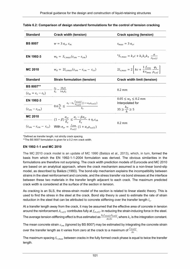
Practical guidance for the design and construction of liquid-retaining structures
101
Table 6.2: Comparison of design standard formulations for the control of tension cracking
Standard Crack width (tension) Crack spacing (tension)
BS 8007 𝑤𝑤 = 3 𝑎𝑎𝑃𝑃𝑠𝑠 𝜀𝜀𝐴𝐴 𝑠𝑠𝐴𝐴𝑎𝑎𝑚𝑚 = 3 𝑎𝑎𝑃𝑃𝑠𝑠
EN 1992-3 𝑤𝑤𝑘𝑘 = 𝑆𝑆𝑠𝑠,𝐴𝐴𝑎𝑎𝑚𝑚(𝜀𝜀𝑎𝑎𝐴𝐴 − 𝜀𝜀𝑃𝑃𝐴𝐴) *𝑆𝑆𝑠𝑠,𝐴𝐴𝑎𝑎𝑚𝑚 = 𝑘𝑘3𝑐𝑐 + 𝑘𝑘1𝑘𝑘2𝑘𝑘4 𝜑𝜑𝜌𝜌𝑝𝑝,𝑒𝑒𝑒𝑒𝑒𝑒
MC 2010 𝑤𝑤𝑎𝑎 = 2𝑙𝑙𝑎𝑎,𝐴𝐴𝑎𝑎𝑚𝑚(𝜀𝜀𝑎𝑎𝐴𝐴 − 𝜀𝜀𝑃𝑃𝐴𝐴 − 𝜀𝜀𝑃𝑃𝑎𝑎) 2𝑙𝑙𝑎𝑎,𝐴𝐴𝑎𝑎𝑚𝑚 = 2 � 𝑘𝑘𝑐𝑐 + 14𝑓𝑓𝑃𝑃𝑎𝑎𝐴𝐴𝜏𝜏𝐴𝐴𝐴𝐴𝑎𝑎
𝜑𝜑𝑎𝑎𝜌𝜌𝑎𝑎,𝑎𝑎𝑓𝑓
�
Standard Strain formulation (tension) Crack width limit (tension)
BS 8007** 𝜎𝜎𝑠𝑠𝐸𝐸𝑠𝑠− 2𝐴𝐴𝑐𝑐ℎ
3𝐴𝐴𝑠𝑠𝐸𝐸𝑠𝑠 0.2 𝑚𝑚𝑚𝑚
(𝜀𝜀𝐴𝐴 = 𝜀𝜀1 − 𝜀𝜀2)
EN 1992-3 0.6 𝜎𝜎𝑠𝑠
𝐸𝐸𝑠𝑠 ≤
𝜎𝜎𝑠𝑠 − 𝑘𝑘𝑐𝑐 𝑒𝑒𝑐𝑐𝑐𝑐;𝑒𝑒𝑒𝑒𝑒𝑒𝜌𝜌𝑠𝑠;𝑒𝑒𝑒𝑒𝑒𝑒
�1 + 𝛼𝛼𝑒𝑒𝜌𝜌𝑠𝑠;𝑒𝑒𝑒𝑒𝑒𝑒�
𝐸𝐸𝑠𝑠
0.05 ≤ 𝑤𝑤𝑘𝑘 ≤ 0.2 𝑚𝑚𝑚𝑚 Interpolated for
35 ≥ℎ𝐷𝐷ℎ≥ 5 (𝜀𝜀𝑎𝑎𝐴𝐴 − 𝜀𝜀𝑃𝑃𝐴𝐴)
MC 2010 (1 − 𝛽𝛽)
𝜎𝜎𝑎𝑎𝑠𝑠𝐸𝐸𝑎𝑎
≤𝜎𝜎𝑎𝑎 − 𝛽𝛽𝜎𝜎𝑎𝑎𝑠𝑠
𝐸𝐸𝑎𝑎+ 𝜂𝜂𝑠𝑠𝜀𝜀𝑎𝑎ℎ
With 𝜎𝜎𝑎𝑎𝑠𝑠 = 𝑓𝑓𝑐𝑐𝑐𝑐𝑐𝑐𝜌𝜌𝑠𝑠,𝑒𝑒𝑒𝑒𝑒𝑒
(1 + 𝛼𝛼𝑎𝑎𝜌𝜌𝑎𝑎,𝑎𝑎𝑓𝑓𝑓𝑓) 0.2 𝑚𝑚𝑚𝑚
(𝜀𝜀𝑎𝑎𝐴𝐴 − 𝜀𝜀𝑃𝑃𝐴𝐴 − 𝜀𝜀𝑃𝑃𝑎𝑎)
*Defined as transfer length, not strictly crack spacing. **The BS 8007 formulation is given for a 0.2 mm crack width.
EN 1992-1-1 and MC 2010
The MC 2010 crack model is an update of MC 1990 (Balázs et al., 2013), which, in turn, formed the basis from which the EN 1992-1-1-2004 formulation was derived. The obvious similarities in the formulations are therefore not surprising. The crack width prediction models of Eurocode and MC 2010 are based on an analytical approach, where the crack mechanism assumed is a non-linear bond-slip model, as described by Balázs (1993). The bond-slip mechanism explains the incompatibility between strains in the steel reinforcement and concrete, and the stress transfer via bond stresses at the interface between these two materials in the transfer length adjacent to each crack. The maximum predicted crack width is considered at the surface of the section in tension.
As cracking is an SLS, the stress-strain model of the section is related to linear elastic theory. This is used to find the stress in the steel at the crack. Bond slip theory is used to estimate the rate of strain reduction in the steel that can be attributed to concrete stiffening over the transfer length 𝑙𝑙𝑎𝑎.
At a transfer length away from the crack, it may be assumed that the effective area of concrete in tension around the reinforcement 𝐴𝐴𝑃𝑃,𝑎𝑎𝑓𝑓𝑓𝑓 contributes fully at 𝑓𝑓𝑃𝑃𝑎𝑎,𝑎𝑎𝑓𝑓𝑓𝑓 in reducing the strain-inducing force in the steel.
The average tension-stiffening effect is thus estimated as 𝑘𝑘𝑐𝑐𝑓𝑓𝑐𝑐𝑐𝑐,𝑒𝑒𝑒𝑒𝑒𝑒𝐴𝐴𝑐𝑐,𝑒𝑒𝑒𝑒𝑒𝑒
𝐴𝐴𝑎𝑎.𝐸𝐸𝑎𝑎, where 𝑘𝑘𝑎𝑎 is the integration constant.
The mean concrete strain ε𝑃𝑃𝐴𝐴 (ignored by BS 8007) may be estimated by integrating the concrete strain
over the transfer length as it varies from zero at the crack to a maximum of 𝑓𝑓𝑐𝑐𝑐𝑐,𝑒𝑒𝑒𝑒𝑒𝑒
𝐸𝐸𝑃𝑃.
The maximum spacing 𝑆𝑆𝑠𝑠,𝐴𝐴𝑎𝑎𝑚𝑚 between cracks in the fully formed crack phase is equal to twice the transfer length.

Practical guidance for the design and construction of liquid-retaining structures
102
The mean strain in EN 1992 is required to be above 0.6 𝜎𝜎𝑠𝑠𝐸𝐸𝑠𝑠
(where 𝜎𝜎𝑎𝑎 is the steel stress and 𝐸𝐸𝑎𝑎 is the
steel modulus) as the model was developed for the stabilised cracking phase. At low steel stresses, the crack formation phase equation should be used (see Section 6.4.1). The MC 2010 updated the mean strain limit (see Table 6.3) to better match fundamental assumptions in the derivation: the limit corresponds to the stress 𝜎𝜎𝑎𝑎𝑠𝑠 that would cause strain compatibility between the steel and concrete to be lost at the end of the transfer length.
One may be tempted to wonder why the shrinkage strain term in the MC 2010 strain estimate is not moderated by a restraint factor. Note that this equation estimates the average strain difference between the steel and the concrete in the effective tension area around the steel. Thus, the relevant restraint here is the restraint of the steel on the concrete surrounding it, not that of the structural element at its ends or edges. Prior to bond failure, the steel will restrain all shrinkage of the concrete immediately surrounding it, thus giving an implicit restraint factor of 1.0.
In EN 1992-1-1-2004 and MC 2010, the formulae provide the characteristic value of the crack width as a 95% fractile (Lapi et al., 2018).
The formulations of EN 1992 and MC 2010 were developed for the direct tension case. The EN 1992 compatibility relationship was modified to fit flexural cracking behaviour, distinguishing between pure tensile and flexural strain distributions with the distribution of the strain coefficient k2, which is given a value of 0.5 for flexure and 1.0 for pure tension. For combined tension and flexure, intermediate values of k2 may be calculated from the relationship k2 = (ε1 + ε2)/2ε1, where ε1 and ε2 are the greater and lesser tensile strains, respectively, at the boundaries of the section that are considered, assessed on the basis of a cracked section. All k-values of the EN 1992 and MC 2010 crack models are empirical factors. Table 6.3 summarises a comparison between the k-factors of EN 1992 and MC 2010. The equations for mean strain in Table 6.1 and Table 6.2 are stated by Balázs et al. (2013) to be accurate for direct tensile loading, but approximate for bending. However, the accuracy in the latter case is deemed to be sufficient3.
Table 6.3: Summary of ki values as applied to maximum crack spacing formulation
Coefficient Strictly analytical (B
EN 1992 EN 1992 (France)
EN 1992 (Germany)
MC 2010
Bond ribbed bars
0.5 k1 = 0.8 0.8 1 fct/τbms = 1/1.8 = 0.556
Type of loading, k2
1 1 (tension) 0.5 (bending)
1 (tension) 0.5 (bending)
1 1
Concrete cover, k3
0 3.4 (= 1.7 x 2) includes factor Sr,max/Srm = 1.7
c ≤ 25: 3,4 c > 25: 3,4 (25/c)2/3
0 2 x k1 2 x 1.0 = 2
Factor, k4 Sr,max/Srm
2 x 0.5 (= 1.0)
0.425 (= 1.7 x 0.25)
0.278 (= 1.112 x 0.25)
0.425 (= 1.7 x 0.25)
2 x 0.25 = 0.5
3 In Section 6.3.4, it may be seen that experimental results for bending cracks match predictions better when k2 = 1.0. This “pure tension” assumption is, in fact, in keeping with the fundamental assumption made in the derivation of the crack width equations, which assumes a prism in tension and accepts that cracks are only controlled in the effective tension area. Considering the entire section in the calculation of k2 would violate this assumption.

Practical guidance for the design and construction of liquid-retaining structures
103
The MC 2010 transfer length equation includes the influence of concrete cover on the model, an update of its predecessor, MC 90. Research by researchers such as Caldentey et al. (2013) showed that omitting cover was incorrect, as concrete cover has a significant influence on the transfer length and thus the crack width. The value specified for the coefficient k is smaller than the corresponding k3 value of EN 1992, as the latter formulation is deemed to overestimate the influence of cover. The MC 2010 crack model is deemed to be valid for c ≤ 75 mm.
The MC 2010 standard applies a limit on concrete compressive strength of 0,6 fck(t) to prevent longitudinal cracking under loading, which, in turn, leads to an increase in creep. If a value of 0,4 fck(t) is exceeded under quasi-permanent loading, then creep has a significant effect and the effective elastic modulus for concrete, Ec,eff, is used. A limit of 0,8 fyk under loading is specified for the reinforcement yield strength.
The MC 2010 standard has been proposed as an update of the EN 1992 crack model by the fib TG4.1 working committee on serviceability (Caldentey, 2017), for the following reasons:
• The EN 1992 standard overestimates the influence of concrete cover on crack spacing. • The EN 1992 standard does not include long-term effects such as long-term shrinkage strain and
thus significantly under-predicts crack widths for long-term loading.
BS 8007
South Africa currently uses BS 8007:1987 in the design of liquid-retaining structures, although the British Standards were superceded by the Eurocodes. The BS 8007 crack model is based on the model originally developed by Beeby (1979) from experimental research. The main assumptions of this crack model, in contrast to EN 1992, is that there is no slip between concrete and reinforcement, and bond failure does not occur. Instead, plane sections do not remain plane and shear deformation in the cover zone contributes to the crack width (see Figure 6.3). The model distinguishes between flexural and direct tension loading in the determination of the maximum crack width (see Table 6.1 and Table 6.2).
Figure 6.3: No-slip mechanism of cracking: relationship between c and transfer length (from
the old British Code for structural concrete, CP 110)

Practical guidance for the design and construction of liquid-retaining structures
104
A minimum nominal concrete cover of 40 mm is specified. Crack spacing is assumed to be a function of acr, i.e the distance from the crack considered to the nearest longitudinal reinforcing bar. Guidance on calculating acr is given by references such as Bhatt et al. (2006). The BS 8007 crack model for load-induced cracking does therefore not explicitly determine the crack spacing, although it is implied.
For flexure, the apparent strain at the level of tension reinforcement (εs) is calculated using elastic theory and used to determine the apparent strain at the surface (ε1). In the tension case, the apparent strain (ε1) is equal to the steel strain (εs). The tension stiffening equations conservatively assume a concrete stress at the end of the transfer length of 0.667 and 1 MPa, respectively, for crack widths of 0.2 or 0.1 mm. Interpolation for other crack widths is prohibited, although of course one could conservatively choose the smaller stiffening if need be. The BS 8007 crack width formulations are valid for a limit of 0,8 fy/Es for the strain in the tensile reinforcement, where fy and Es are the yield stress and steel modulus of the reinforcement, respectively. A limit of 0.45 fcu is also placed on the concrete stress for flexural cracking, where fcu is the concrete cube compressive strength at 28 days. In addition, the concrete compressive strength (cube at 28 days) should not be less than 35 MPa.
The BS 8007 standard assumes no bond-slip, which leads to it underestimating the crack spacing compared to EN 1992 and MC 2010 because it only accounts for shear deformation in the cover zone. On the other hand, the mean strain is overestimated for two reasons: the mean concrete strain ε𝑃𝑃𝐴𝐴 is ignored and the tension stiffening effect on the steel strain is underestimated, both resulting in a higher mean strain difference over the transfer length. The underestimation of spacing and overestimation of strain have opposing influences on the estimated crack width. Depending on the design situation, therefore, BS 8007 may either overestimate or underestimate crack widths.
In BS 8007, the predicted crack width is intended to have a 20% chance of being exceeded (Beeby, 1979), so this formulation has intentionally lower reliability than that of EN 1992-1-1 and MC 2010, which targets a 5% probability of exceedance.
Notes
Creep is considered in all crack models for long-term flexure by using the effective modulus of elasticity of concrete. The crack spacing estimated using EN 1992 and MC 2010 is generally in the order of 60 to 80% of the value predicted using BS 8007. This is principally due to the difference in the surface zones used in the calculation of the steel ratio.
6.3.3 Design situations, load types and durations
Typical loading conditions on the main structural elements depend on the configuration of the liquid-retaining structure, mainly circular and rectangular. Water pressure on the liquid-retaining structure walls and base is considered as a quasi-permanent load as liquid-retaining structures undergo slow filling and emptying.
The wall of a liquid-retaining structure tends to be more critical than other elements in the structure with regard to cracking and leakage. Circular configurations result in the worst tension case in the horizontal plane due to hoop stress induced by water pressure on the wall. Smaller bending moments are induced in the wall in the vertical plane, depending on the fixity of the wall base (pinned, fixed or sliding) and top (generally designed as free). The fixity of the base also influences the magnitude and position of the peak hoop tension. A sliding wall base results in the maximum tension in the liquid-retaining structure wall, with no moment in the vertical direction.
Sources such as Reynolds et al. (2008) may be used to calculate the tensile forces and bending moments. The equations use to calculate the service tensile force and vertical bending moment have the form of T = αnγlzr and M = αmγlz3, respectively, where αn and αm are coefficients, γ is the unit weight of water of 10 kN/m3, lz is the height of the wall and r is the radius of the reservoir.

Practical guidance for the design and construction of liquid-retaining structures
105
The coefficients depend on the ratio lz2/2rh. The tensile force for the sliding condition is calculated from T = L.D/2, where L is the liquid load equal to γlz and D is the diameter of the reservoir. This equation can be rewritten as Tsliding = 1,0. γlzr. Tensile forces for the pinned and fixed conditions are between about 0.55 and 0.67 Tsliding, depending on the section thickness. Table 6.4 demonstrates the expected induced forces in the wall of a representative circular liquid-retaining structure (diameter 28 m), depending on the base fixity.
Table 6.4: Summary of calculations of SLS ring tension and vertical bending moment using Table 2.75 of Reynolds et al (2008) for circular reservoir configuration
αn αm T (kN) M (kNm)
H (m)
h (mm) lz22rh Fixed
base Pinned base
Fixed base
Pinned base
Fixed base
Pinned base
Sliding base
Fixed base
Pinned base
Sliding base
5 250 3.57 0.400
0.553 -0 02
0.0133 280.0
387.1 700.0 36.88
16.63 0 5 450 1.98 0.27
4 0.434 - 0.0219 191.
8 303.8 700.0 - 27.38 0
7 250 7.00 0.545
0.670 - 0.0068 534.1
656.6 980.0 - 23.32 0 7 450 3.89 0.421 0.572 0.0275 0.0120 412.6 560.6 980.0 -94.33 41.16 0
A ratio of 4 between wall height and diameter was identified from an industry survey (McLeod, 2013) as being representative of circular reservoirs of up to 10 Mℓ capacity. Circular reservoirs larger than this are generally pre-stressed as the hoop stresses induced increase beyond the limits of an economically reinforced concrete structure.
Rectangular reservoir walls are typically constrained by a fixed base and connected to perpendicular adjacent walls. The top may be free or propped by the roof slab. Horizontal tension in long-edge restrained panels is typically small, significant mostly at the corners. The weight of the roof causes compression in the vertical direction, which is advantageous from a wall crack width perspective. Cantilever or propped cantilever walls with a fixed base undergo flexure in the vertical plane. This configuration results in the critical load case for flexural cracking. At wall intersections of rectangular reservoirs, high bending moments can be induced in the horizontal plane.
Figure 6.4 shows typical rectangular and liquid-retaining structure wall configurations and the associated loading due to water pressure.
Figure 6.4: Rectangular (left) and circular reservoir (right) wall configurations

Practical guidance for the design and construction of liquid-retaining structures
106
As water pressure is considered a quasi-permanent loading, long-term cracking must be checked. Crack models that do not include long-term effects such as long-term shrinkage strain have been shown to under-predict long-term crack widths (McLeod, 2019).
6.3.4 Comparison to experimental results
Model bias and uncertainty of the crack width prediction models of BS 8007, EN 1992 and MC 2010 were quantified by McLeod (2019) for use in probabilistic analyses of crack width prediction models. The ratio of the maximum measured crack width over the predicted crack width (wexp / wpredict), or model factors, are calculated for a database of experiments and used statistically to quantify the bias (mean value of model factors) and uncertainty (coefficient of variation) of the models.
A database of experimental results for load-induced cracking was compiled, obtaining maximum measured crack widths. The experimental measured material properties, loading and sample geometry are utilised in the calculation of the predicted maximum crack widths for the design formulations listed below. The wexp / wpredict ratios were then determined for each crack model and load case. Flexural and tension cracking due to both short-term and long-term loading were evaluated.
The model uncertainty ratios were determined for the following crack models:
• EN 1992 • EN 1992 with a shrinkage strain term added for long-term cracking • MC 2010 – k2 = 1.0 and 0.5 respectively (flexure only) • BS 8007 with a crack width limit of 0.2 and 0.1 mm respectively
The EN 1992 formulation was assessed to see if a simple modification by the inclusion of all long-term effects would be sufficient to improve its performance over time.
The model factor statistics for all load cases are summarised in Table 6.5. The sample sizes for the short-term flexural and tension loading cases were large enough for reasonable estimates of mean values (bias) and uncertainty (CoV). The sample size for long-term tension cracking was very small at 15, reducing to 8 after averaging repeat samples. Only an indication of the long-term model uncertainty could be obtained. It is clear from the high bias of MC 2010 with k2 = 0.5 that this parameter choice is not suitable, even for flexure. If MC 2010 is used, the value of k2 should be taken as unity for both tension and flexure, as is done in the published model.
Table 6.5: Model uncertainty statistical parameters of crack prediction models (all data)
Load case Statistical parameter
EN 1992 MC 2010 k2 = 1
MC 2010 k2 = 0.5
BS 8007 w = 0.2 mm
BS 8007 w = 0.1 mm
Short-term flexure
Mean 1.107 1.052 1.551 1.185 1.112 cov 0.379 0.376 0.411 0.380 0.459 Count 164 164 164 164 164
Long-term flexure
Mean 1.443 1.127 1.601 1.502 1.514 cov 0.331 0.380 0.353 0.336 0.357 Count 30 30 30 30 30
Short-term tension
Mean 0.742 0.984 - 1.271 1.430 cov 0.247 0.324 - 0.228 0.258 Count 82 82 - 82 82
Long-term tension
Mean 0.895 0.988 - 1.318 1.603 cov 0.246 0.216 - 0.453 0.495 Count 8 8 - 8 8

Practical guidance for the design and construction of liquid-retaining structures
107
The database contained several observed crack widths larger than 0.4 mm, which falls well outside the range of interest for liquid-retaining structures. In Table 6.6, the model factor statistics are recalculated, excluding all samples with cracks in excess of 0.4 mm. Table 6.7 then interprets the bias of the models, noting underprediction (-) or overprediction (+) in bold percentages for each model and load case.
Notably, all models have high coefficients of variation. The MC 2010 standard seems to be the most consistent predictor of crack widths.
Table 6.6: Model uncertainty statistical parameters of crack prediction models (< 0.4 mm cracks)
Load case Statistical parameter
EN 1992 MC 2010 k2 = 1
BS 8007 w = 0.2 mm
Short-term flexure
Mean 0.989 0.942 1.106 CoV 0.492 0.509 0.398 Count 144 144 144
Long-term flexure
Mean 1.443 1.127 1.502 CoV 0.331 0.380 0.336 Count 30 30 30
Short-term tension
Mean 0.780 1.079 1.257 CoV 0.242 0.294 0.265 Count 82 82 82
Long-term tension*
Mean 0.895 0.988 1.318 CoV 0.246 0.216 0.453 Count 8 8 8
* Very little data is available. Estimates include data from cracks up to 1.0 mm.
Table 6.7: Prediction bias of different crack prediction models
Load case Statistical parameter
EN 1992 MC 2010 k2 = 1
BS 8007 w = 0.2 mm
Short-term flexure
MF mean 0.989 0.942 1.106 pred/exp 1.01 1.06 0.90 ± pred 1% 6% -10%
Long-term flexure
Mean 1.443 1.127 1.502 pred/exp 0.69 0.89 0.67 ± pred -31% -11% -33%
Short-term tension
Mean 0.78 1.079 1.257 pred/exp 1.28 0.93 0.80 ± pred 28% -7% -20%
Long-term tension*
Mean 0.895 0.988 1.318 pred/exp 1.12 1.01 0.76 ± pred 12% 1% -24%
*Very little is data available. Estimates include data from cracks up to 1.0 mm.
Figure 6.5 compares the experimentally observed crack widths to the corresponding predictions by MC 2010 and BS 8007. The high uncertainty of predictions from both models is evident in all load cases. For short-term bending, the predictive capacity of the two models is comparable: MC 2010 has a somewhat lower bias, but higher variability than BS 8007. The BS 8007 standard mildly overestimates short-term bending, but here the somewhat lower bias of MC 2010 is barely noticeable due to the high CoV of predictions. The BS 8007 standard tends to substantially overestimate crack widths for short-term tension and long-term bending, while MC 2010 has notably less bias, but more scatter.

Practical guidance for the design and construction of liquid-retaining structures
108
Figure 6.5: Experimental vs MC 2010 and BS 8007 predicted crack widths for: (a) short-term
bending, (b) long-term bending, (c) short-term tension and (d) long-term tension
6.3.5 Assessment of required reinforcement needs
Typical liquid-retaining structure configurations, representative of bending and tension load cases, respectively, were chosen to assess the reinforcement required to meet a 0.2 mm crack width limit for the crack models BS 8007, EN 1992 and MC 2010. Referring to Figure 6.4, wall sections of unit lengths of a rectangular and circular liquid-retaining structure, respectively, were considered. The reinforcement required was determined for each of the crack models BS 8007, EN 1992 and MC 2010, for short- and long-term cracking. The wall geometries chosen are summarised in Table 6.8. Material properties, concrete cover and reinforcement diameter were constant for all configurations.
Table 6.8: Parameters of representative liquid-retaining structures
Parameter Bending rectangular liquid-retaining structure
Tension circular liquid-retaining structure
Liquid-retaining structure diameter, D (m) - 25, 30 Wall height, H (m) 5, 6, 7 5, 6, 7 Section thickness, h (mm) 500-850 300 Concrete cover, c (mm) 40 Reinforcement diameter, φ (mm) 20 Concrete compressive strength, fck (MPa) 30/37 Concrete creep factor, long term 1.7 Long-term shrinkage strain, εsh 0, -125µε, -350µε

Practical guidance for the design and construction of liquid-retaining structures
109
For the bending case, wall H/h ratios were in the order of about 7.5 to 10; the latter as a practical upper limit to what is considered suitable for rectangular liquid-retaining structures. For the tension case, D/H ratios that correspond to circular liquid-retaining structure volumes of about 3 to 5 Mℓ were selected. The latter capacity is considered to be at the upper limit that is suitable for a reinforced concrete liquid-retaining structure. For larger, circular reservoirs, reinforced concrete liquid-retaining structures can no longer compete economically, and pre-stressed structures are preferred.
Considering long-term loading, a nil value for long-term shrinkage strain was selected for the MC 2010 crack model only, to enable comparisons to BS 8007 and EN 1992. The influence of long-term shrinkage strain on the reinforcement ratio, using MC 2010, was investigated using shrinkage strains of -125 µε (low shrinkage aggregates in high humidity) and -350 µε (high shrinkage aggregates in low humidity). The effective concrete modulus was used for long-term cracking to include the effect of creep.
The required reinforcement ratios to resist increasing levels of bending are shown in Figure 6.6 and Figure 6.7 for short-term and long-term loading, respectively. This is determined using BS 8007, EN 1992 and MC 2010. Figure 6.8 and Figure 6.9 show the same for tension. The reinforcement ratios are per face for pure tension cracking.
The EN 1992 standard is generally conservative, compared to BS 8007, in particular for tension loading. It should be noted that the BS 8007 crack model for tension loading is independent of the concrete modulus, resulting in the same reinforcement ratio for short- and long-term loading.
For bending, MC 2010 results in an increase in required reinforcement compared to BS 8007, which renders 21% (short term) to 31% (long term). For tension, MC 2010 typically requires about 18% more reinforcing than BS 8007.
Considering the requirements of MC 2010 when including shrinkage strain in the long-term estimates, Figure 6.7 and Figure 6.9 show that long-term shrinkage strain may result in a significant increase (+39%) in the reinforcement ratio for high shrinkage strains. However, at low shrinkage strains, the increase in the reinforcement required is nominal (5 to 10%). This provides motivation to ensure a proper concrete mix design and good quality control in construction to limit shrinkage. The higher reinforcement requirement of MC 2010, compared to EN 1992 and BS 8007, is expected as this model accounts for long-term shrinkage strain, while BS 8007 and EN 1992 do not.
Figure 6.6: Reinforcement ratios for short-term bending, wk = 0.2 mm
0,6
0,8
1
1,2
1,4
0,2 0,3 0,4 0,5 0,6 0,7
M/b
d2
%As
BS 8007
+21%

Practical guidance for the design and construction of liquid-retaining structures
110
Figure 6.7: Reinforcement ratios for long-term bending, wk = 0.2 mm
Figure 6.8: Reinforcement ratios for short-term tension, wk = 0.2 mm
Figure 6.9: Reinforcement ratios for long-term tension, wk = 0.2 mm
0,6
0,7
0,8
0,9
1
1,1
1,2
1,3
1,4
0,35 0,40 0,45 0,50 0,55 0,60 0,65 0,70 0,75 0,80 0,85
M/b
d2
%As
BS 8007EN 1992MC 2010 esh 0MC 2010 esh 125MC 2010 esh 350
300
350
400
450
500
550
0,5 0,6 0,7 0,8 0,9 1 1,1
T kN
%As
BSEN 1992MC 2010
300
350
400
450
500
550
0,5 0,6 0,7 0,8 0,9 1 1,1 1,2
T kN
%As
BSEN 1992MC 2010 esh 0MC 2010 esh125MC 2010 esh 350
+ 26% + 18% + 10%
+17%
+31% +26%
+ 39%

Practical guidance for the design and construction of liquid-retaining structures
111
6.4 PREDICTION OF RESTRAINT-INDUCED CRACK WIDTHS
6.4.1 Restraint-induced actions and restraint types
In the presence of restraint, thermal and shrinkage contractions in concrete result in the development of stresses. Thermally induced cracking may be long term, such as contraction due to seasonal temperature variation, or early-age (short-term), such as cooling from the peak heat of hydration to ambient temperature within hours or days of casting of the concrete element. Shrinkage is considered long term. The immature concrete capacity determines cracking behaviour in the case of early-age induced stresses, while mature concrete has increased its capacity to resist long-term restraint-induced stresses.
Two primary types of restraint are distinguished: end restraint and edge restraint. The type of restraint dramatically impacts on the crack widths that may be expected. In both cases, the maximum crack spacing is determined from bond slip theory, (i.e. Smax as for EN 1992 or MC 2010), but the crack-inducing strain differs substantially, depending on the restraint type.
End restraint
End restraint considers members that are constrained by stiffer elements at opposing ends. In this configuration, restrained contraction gives rise to direct tensile stress in the element. Normally, the stress level would not be sufficient to develop a stabilised crack pattern, so the assumptions that hold for the crack formation phase (see Section 6.3.1) is used to derive the estimate of crack inducing strain as follows:
ε𝑎𝑎𝐴𝐴 − ε𝑃𝑃𝐴𝐴 = 0.5 𝛼𝛼𝑎𝑎𝑘𝑘𝑃𝑃𝑘𝑘𝑓𝑓𝑃𝑃𝑎𝑎,𝑎𝑎𝑓𝑓𝑓𝑓
𝐸𝐸𝑎𝑎�1 +
1𝛼𝛼𝑎𝑎𝜌𝜌
�
In end-restrained elements, therefore, the width of the crack depends mainly on the concrete tensile capacity and amount of reinforcing (see Section 6.3.1 for a discussion).
According to EN 1993, the steel ratio ρ is based on the full section thickness. This may be a mistake as it contradicts the assumption (used in the equivalent derivation for the fully formed crack phase) that the crack width only needs to be controlled in the effective tension area. It also creates an anomaly, since the crack spacing Sr,max is derived using the effective steel ratio ρp,eff, which is based on the effective area of concrete in tension surrounding the reinforcement.
Beeby (1990) reported good agreement between experimental results (Jaccoud, 1987) and crack widths derived using this equation for end-restrained members in the crack formation phase.
Edge restraint
Edge restraint considers members that are constrained by a stiffer element along one or more edge. In this configuration, the adjacent concrete also serves to distribute cracks along with the steel. The crack-inducing strain is then equal to the amount of restrained strain as follows:
ε𝑎𝑎𝐴𝐴 − ε𝑃𝑃𝐴𝐴 = 𝑅𝑅𝑎𝑎𝑚𝑚 𝜀𝜀𝑓𝑓𝑠𝑠𝑎𝑎𝑎𝑎
or, according to the more detailed description of CIRIA C660 (Bamforth, 2007), as follows:
𝜀𝜀𝑃𝑃𝑠𝑠 = 𝑅𝑅𝑎𝑎𝑚𝑚( α𝑃𝑃[𝑇𝑇1 + 𝑇𝑇2] + 𝜀𝜀𝑃𝑃𝑎𝑎 + 𝜀𝜀𝑃𝑃𝑎𝑎 ) - 0.5𝜀𝜀𝑃𝑃𝑎𝑎𝑎𝑎
In edge-restrained elements, therefore, the width of the crack depends mainly on the amount of retrained strain.
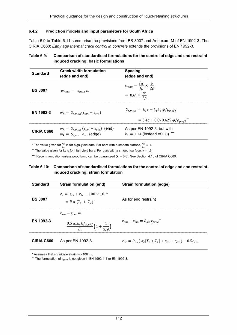
Practical guidance for the design and construction of liquid-retaining structures
112
6.4.2 Prediction models and input parameters for South Africa
Table 6.9 to Table 6.11 summarise the provisions from BS 8007 and Annexure M of EN 1992-3. The CIRIA C660: Early age thermal crack control in concrete extends the provisions of EN 1992-3.
Table 6.9: Comparison of standardised formulations for the control of edge and end restraint-induced cracking: basic formulations
Standard Crack width formulation (edge and end)
Spacing (edge and end)
BS 8007 𝑤𝑤𝐴𝐴𝑎𝑎𝑚𝑚 = 𝑠𝑠𝐴𝐴𝑎𝑎𝑚𝑚 𝜀𝜀𝑠𝑠 𝑠𝑠𝐴𝐴𝑎𝑎𝑚𝑚 =
𝑓𝑓𝑃𝑃𝑎𝑎 𝑓𝑓𝐴𝐴
× 𝜑𝜑2𝜌𝜌
= 0.6∗ × 𝜑𝜑2𝜌𝜌
EN 1992-3 𝑤𝑤𝑘𝑘 = 𝑆𝑆𝑠𝑠,𝐴𝐴𝑎𝑎𝑚𝑚(𝜀𝜀𝑎𝑎𝐴𝐴 − 𝜀𝜀𝑃𝑃𝐴𝐴) 𝑆𝑆𝑠𝑠,𝐴𝐴𝑎𝑎𝑚𝑚 = 𝑘𝑘3𝑐𝑐 + 𝑘𝑘1𝑘𝑘4 𝜑𝜑/𝜌𝜌𝑝𝑝,𝑎𝑎𝑓𝑓𝑓𝑓
= 3.4𝑐𝑐 + 0.8×0.425 𝜑𝜑/𝜌𝜌𝑝𝑝,𝑎𝑎𝑓𝑓𝑓𝑓**
CIRIA C660 𝑤𝑤𝑘𝑘 = 𝑆𝑆𝑠𝑠,𝐴𝐴𝑎𝑎𝑚𝑚 (𝜀𝜀𝑎𝑎𝐴𝐴 − 𝜀𝜀𝑃𝑃𝐴𝐴) (end) 𝑤𝑤𝑘𝑘 = 𝑆𝑆𝑠𝑠,𝐴𝐴𝑎𝑎𝑚𝑚 𝜀𝜀𝑃𝑃𝑠𝑠 (edge)
As per EN 1992-3, but with 𝑘𝑘1 = 1.14 (instead of 0.8). ***
* The value given for 𝑓𝑓𝑐𝑐𝑐𝑐 𝑓𝑓𝑏𝑏
is for high-yield bars. For bars with a smooth surface, 𝑓𝑓𝑐𝑐𝑐𝑐 𝑓𝑓𝑏𝑏
= 1.
** The value given for k1 is for high-yield bars. For bars with a smooth surface, k1=1.6.
*** Recommendation unless good bond can be guaranteed (k1 = 0.8). See Section 4.13 of CIRIA C660. Table 6.10: Comparison of standardised formulations for the control of edge and end restraint-
induced cracking: strain formulation
Standard Strain formulation (end) Strain formulation (edge)
BS 8007 𝜀𝜀𝑠𝑠 = ε𝑃𝑃𝑎𝑎 + ε𝑎𝑎𝑎𝑎 − 100 × 10−6
= 𝑅𝑅 𝛼𝛼 (𝑇𝑇1 + 𝑇𝑇2) *
As for end restraint
EN 1992-3
ε𝑎𝑎𝐴𝐴 − ε𝑃𝑃𝐴𝐴 =
0.5 𝛼𝛼𝑎𝑎𝑘𝑘𝑃𝑃𝑘𝑘𝑓𝑓𝑃𝑃𝑎𝑎,𝑎𝑎𝑓𝑓𝑓𝑓
𝐸𝐸𝑎𝑎�1 +
1𝛼𝛼𝑎𝑎𝜌𝜌
� ε𝑎𝑎𝐴𝐴 − ε𝑃𝑃𝐴𝐴 = 𝑅𝑅𝑎𝑎𝑚𝑚 𝜀𝜀𝑓𝑓𝑠𝑠𝑎𝑎𝑎𝑎**
CIRIA C660 As per EN 1992-3 𝜀𝜀𝑃𝑃𝑠𝑠 = 𝑅𝑅𝑎𝑎𝑚𝑚( α𝑃𝑃[𝑇𝑇1 + 𝑇𝑇2] + 𝜀𝜀𝑃𝑃𝑎𝑎 + 𝜀𝜀𝑃𝑃𝑎𝑎 ) − 0.5𝜀𝜀𝑃𝑃𝑎𝑎𝑎𝑎
* Assumes that shrinkage strain is <100 µε. ** The formulation of 𝜀𝜀𝑓𝑓𝑠𝑠𝑎𝑎𝑎𝑎 is not given in EN 1992-1-1 or EN 1992-3.

Practical guidance for the design and construction of liquid-retaining structures
113
Table 6.11: Comparison of standardised formulations for the control of edge and end restraint-induced cracking: input parameters
Standard Parameters (end) Parameters (edge)
EN 1992-3
𝑘𝑘𝑃𝑃 = 1.0 𝑘𝑘 = 1.0 for h < 0.3 m 𝑘𝑘 = 0.65 for h ≥ 0.8 m 𝛼𝛼𝑎𝑎 = 𝐸𝐸𝑎𝑎/𝐸𝐸𝑃𝑃
0 ≤ 𝑅𝑅𝑎𝑎𝑚𝑚 ≤ 0.5 (Annexure L)
CIRIA C660 As per EN 1992-3 but 𝑘𝑘 = 0.75 for h ≥ 0.8 m
See summary in discussion below
The provisions for edge restraint according to EN 1992-3 and CIRIA C660 predict smaller crack widths, and therefore require less reinforcement than BS 8007 provisions. This is primarily due to the difference in the tension zones in the steel ratio 𝜌𝜌𝑝𝑝,𝑎𝑎𝑓𝑓𝑓𝑓 used to estimate the crack spacing. The EN 1992-1-1 standard derives 𝜌𝜌𝑝𝑝,𝑎𝑎𝑓𝑓𝑓𝑓 using the effective area of concrete in tension surrounding the reinforcement 𝐴𝐴𝑃𝑃,𝑎𝑎𝑓𝑓𝑓𝑓 based on the surface zone to a depth of ℎ𝑎𝑎𝑓𝑓𝑓𝑓 = 2.5(𝑐𝑐 + 𝜑𝜑/2), while the surface zone used by BS 8007 is h/2 or 250 mm, whichever is smaller. The spacing estimates of EN 1992-1-1 are in the order of 60 to 80% of the BS 8007 estimates.
End restraint requires substantially more reinforcement and should be avoided where possible (see Section 6.4.3).
The predicted crack width due to thermal contraction is directly related to the temperature reductions quantified respectively by T1 for early-age and T2 for seasonal variation. Viljoen and Retief (2015) derived T1 and T2 values for use in South Africa on principles similar to that done by Bamforth (2007) for the UK, but accounting for local cements and climate.
6.4.3 Practical design considerations
Restraint-induced action may be reduced by reducing restraint or by reducing the crack-inducing strain. Edge restraint cannot be avoided, but end restraint can and should be avoided by choosing pour sequences smartly (i.e. sequential with edge restraint rather than infill with end restraint) or by providing movement joints4. Narrow infill panels where end restraint cannot be avoided provide limited zones of heavier reinforcing.
The crack-inducing strain can be reduced by limiting thermal contraction and shrinkage. Proper mix design then becomes important, including blended cements with GGBS or fly ash to reduce heat of hydration, low water-to-cement ratios and low shrinkage aggregates, with a low coefficient of thermal expansion.
6.5 CRACK WIDTH LIMITS
6.5.1 Principles
In the SLS, crack widths are limited for reasons related to aesthetics, the prevention of leakage and durability considerations.
4 From a maintenance perspective, it is ideal to minimise the number of movement joints in a structure. Creating leak-proof joints also requires extra care during construction, including suitable surface preparation and difficulty in achieving proper compaction around water bars.

Practical guidance for the design and construction of liquid-retaining structures
114
Cracks that penetrate the entire section depth, so-called “through cracks”, are more prone to leaks than cracks that only penetrate part of the section. Through cracks are generally the result of dominant tensile loading or restraint action. Cracks due to bending only penetrate the part of the section in tension, leaving the compression block intact.
Cracks can self-heal in the presence of water due to calcium hydroxide converting to calcium carbonate (limestone) deposits. The probability and rate of self-healing are affected by the crack width and the flow rate through the crack.
Durability considerations include carbonation, chloride attack and sulphate attack. Wide cracks will aid the ingress of corrosive substances. However, research indicates crack widths below 0.4 mm to be surprisingly uncorrelated with long-term corrosion. Porosity of concrete may mean that corrosive substances reach the steel even in the absence of cracks. Alternatively, the self-healing of cracks may prevent ingress.
Economic optimisation dictates that where substantial adverse consequences may be expected in case of failure, greater investment in reducing the probability of such failure is warranted. For this reason, differentiation is made between consequence classes (or tightness classes). Structures where tightness, aesthetics and/or durability are more important are therefore designed according to stricter crack width limits.
6.5.2 Discussion of available research
Aesthetic considerations
Aesthetic acceptability is highly subjective and will depend on the viewing distance. It is reasonable to assume that this consideration will be different for water towers in public view compared to buried reservoirs. Research typically considers crack widths in buildings, and there EN 1992-1-1 and BS 8110 (withdrawn) limits crack widths to 0.3 mm for aesthetic reasons. This value is visible at a viewing distance of about 3 m. In liquid-retaining structures, however, the residue that forms due to the self-healing of cracks can add to the visibility and unsightliness of cracks.
Practical experience with liquid-retaining structures is that cracks less than 0.1 mm self-heal almost immediately and will be barely noticeable; cracks of 0.2 mm can self-heal in days and will be noticeable, while cracks of 0.3 mm can self-heal within a few weeks, but will leave an unsightly calcite scar.
Autogenous healing
Self-healing or autogenous healing is the ability of concrete to repair itself due to calcite formation in the cracks, which will reduce the crack width. Several mechanisms contribute to autogenous healing, primarily the precipitation of calcium carbonate, but also the continued hydration of hardened concrete resulting in the growth of hydration products and the deposition of debris. These mechanisms and their interactions are not yet fully understood, with research ongoing.
The rate decrease of flow through a crack has been found to depend on the crack width and flow rate. Leakage rates are also influenced by crack surface roughness. Research has showed a rapid decrease in the initial flow through a crack within the first stages of testing (Allen, 1983; Teal, 2016), but complete healing is not achieved for all crack widths, nor equally quickly (Ziari and Kianoush, 2009a; Ziari and Kianoush, 2009b).
Edvardsen (1999) performed extensive permeability testing for a range of hydraulic ratios and through crack widths. In addition, she imitated the typical opening and closing of the cracks over a 24-hour period, which may occur in practice in liquid-retaining structures due to liquid level changes. To this end, she cycled the crack width by increasing their width by 10 and 30%, respectively, over each 24-hour period.

Practical guidance for the design and construction of liquid-retaining structures
115
The crack width limits she proposed based on this research are summarised in Table 6.12. The EN 1992-3 limits for through cracks in tightness class 1 (see Section 6.5.3) roughly correspond to her 30% cycle values.
Table 6.12: Permissible crack widths for autogenous healing (Edvardsen, 1999)
Hydraulic gradient (m/m) 𝒘𝒘𝒌𝒌(mm) (𝚫𝚫𝒘𝒘 < 𝟏𝟏𝟒𝟒%)
𝒘𝒘𝒌𝒌(mm) (𝟏𝟏𝟒𝟒% < 𝚫𝚫𝒘𝒘 < 𝟑𝟑𝟒𝟒%)
40 0.10-0.15 ≤0.10 25 0.15-0.20 0.10-0.15 15 0.20-0.25 0.15-0.2
Atkinson (2013), commenting on Edvardsen (1999), stated that the self-healing crack width limits for a maximum of 10% cycling load were more in keeping with those found to be reasonable in practice.
Figure 6.10, from Jones (2008), illustrates autogenous healing of through cracks found by Lohmeyer (1984) and Meichsner (1992), compared to the limits specified by EN 1992-3 for tightness class 1.
Figure 6.10: Comparison of EN 1992-3 through crack width limits to research findings (from Jones, 2008)
Ziari and Kianoush (2009a) performed self-healing tests on through cracks in reinforced concrete panels under a constant water head of 5 m. Continuous flow of water (leakage) was only effectively established for cracks larger than 0.25 mm. The flow rate through these cracks dropped significantly over the first seven hours and the cracks eventually self-healed.
Yi et al. (2011) tested the permeability of 50 mm thick sections with through crack widths of 0.03 to 0.1 mm over a range of water pressures. All cracks showed signs of autogenous healing, but some did not heal completely. They recommended an allowable crack width of 0.1 mm for a hydraulic pressure of 10 kN/m2 or a hydraulic ratio of 20, with a reduction in crack width to 0.05 mm for a hydraulic pressure of 25 kN/m2 or a hydraulic ratio of 50. The small section depth of the tests makes it problematic to apply the result for liquid-retaining structures, as the hydraulic ratio may not map accurately to that of EN 1992-3. Still, considering the 50 mm thickness of the samples, this research would suggest that EN 1992-3 is on the conservative side for crack widths in the region of 0.1 mm.
McLeod (2013) reported on research on autogenous healing performed at the University of KwaZulu-Natal. Case studies and experimental research showed that self-healing does indeed occur, evidenced in some cracks as large as 0.4 mm. Cracks of 0.2 mm and less sealed within 72 hours in most cases.
Ziari and Kianoush (2009b), in testing on panels under flexure, found that the depth of the compression zone played a key role in leakage, together with the crack width. For crack widths up to 0.6 mm and depths of 200 mm, leakage did not occur.

Practical guidance for the design and construction of liquid-retaining structures
116
Crack widths and corrosion
Due to the compression-tension nature, flexure-induced cracks do not pass through the entire section thickness and are of lesser concern with regard to potential leakage. As such, EN 1992-3 allows for crack widths of up to 0.3 mm in cases of flexure in typical, less aggressive environments, provided that the element is not subject to alternate action. The 0.3 mm limit is mainly based on aesthetic considerations.
The effect of crack widths on corrosion is a highly debated topic. While there is agreement that greater crack widths accelerate the initiation of corrosion by allowing the penetration of carbon dioxide, there is debate as to whether corrosion propagation in the long term is affected by crack width. Numerous research projects (Schiessl and Raupach, 1997; Darwin et al., 1985; Sagüés et al., 2001; Oesterle, 1997) have reported no long-term correlation between corrosion propagation and crack widths of the range typically found in liquid-retaining structures (0.05 to 0.4 mm) under service loads. Using cyclic chloride exposure, Schiessl and Raupach (1997) investigated the effect of crack widths on the initiation and propagation of corrosion from chloride attack and found that, after 24 weeks, increasing corrosion rate was noted with increasing crack width, However, after 88 weeks, no pronounced difference in corrosion propagation was noted between the different crack width samples. Thus, the effect of crack widths on corrosion rate decreases with time and is confirmed by other research (Schiessl, 1976; Yachida, 1987; Beeby, 1978; Schiessl and Woelfel, 1986). Other research (Otieno et al., 2010), however, found that crack widths wider than ~0.4 mm showed considerably higher corrosion rates than incipient cracks.
Although there is no consensus on the exact mechanism that negates the effect of crack widths on corrosion propagation, the general hypothesis points to the autogenous healing (self-healing) of cracks by calcium carbonate precipitation (Arya and Ofori-Darko, 1996; Ramm and Biscoping, 1998) and/or mechanical clogging (Tuutti, 1978) of the cracks by means of aggregate or dust as the main reasons (Hornbostel and Geiker, 2017). This is supported by findings (Otieno et al., 2010) that showed that cyclic reloading (which would again crack previously autogenously healed samples) caused small increases in corrosion rates, showing that, for cases of cyclic loading, autogenous healing has less of a positive effect on hindering corrosion propagation.
Although a number of projects have been undertaken on the topic of the effect of cracks on corrosion, there is not enough decisive agreement between the findings to be able to specify a crack width beyond which the threat of corrosion can be disregarded. Generally, it seems that the quantity and quality of concrete cover and adequate compaction are more of a decisive factor for corrosion propagation than surface crack widths (Schiessl and Raupach, 1997; Houston and Ferguson 1972; Nishiyama 1975; Shaikh 2018). Given the above, it seems reasonable that a crack width limit of 0.3 mm should be proposed for cases of flexure that are not subject to alternate action or where it may be demonstrated that a sufficient portion of the section will permanently remain in compression.
6.5.3 Limits from various design standard formulations
Design formulations in most standards differentiate between reliability classes, tightness classes, exposure classes and/or the importance of aesthetics; and provide crack width limits accordingly.
Table 6.13 paraphrases the tightness classes from EN 1992-3. Tightness class 1 or 2 generally applies to liquid-retaining structures. Eurocode allows for the maximum allowable crack width, wk1, to be defined in the National Annexes of individual member countries.
Table 6.14 provides a summary of the crack width limits from various international standards, including BS 8007, and recommends crack width limits for tightness class 1 of EN 1992-3. In the latter, the crack width limit for through cracks depends on the water head-to-section thickness ratio, in response to research findings that high flow rates reduce the likelihood of autogenous healing.

Practical guidance for the design and construction of liquid-retaining structures
117
Table 6.13: Tightness classes from EN 1992-3
Tightness class
Requirements for leakage Description
0 Some degree of leakage is acceptable, or leakage of liquids is irrelevant.
As for general structures.
1
Leakage to be limited to a small amount. Some surface staining or damp patches are acceptable.
Through cracks should be limited to wk1. The provisions for general structures (0.3 mm) apply where the full thickness of the section is not cracked and where the service strain range is less than 150 x 10-6 and where there is a minimum compression zone of xmin = 50 mm or 0.2 hours.
2 Leakage to be minimal. Appearance not to be impaired by staining.
Through cracks should generally be avoided unless appropriate measures (e.g. liners or water bars) have been incorporated.
3 No leakage is permitted. Generally, special measures (e.g. liners or pre-stress) will be required to ensure liquid-tightness.
Table 6.14: Comparison of crack width limits from various standards
Standard Conditions Special condition 𝒘𝒘𝑷𝑷𝑷𝑷𝑨𝑨 (mm)
BS 8007 Severe/very severe exposure 0.2 For aesthetic considerations 0.1
EN 1992-3
Tightness class 1 Limit depends on ratio hydrostatic head (hD) to wall thickness (h). Intermediate values of hD/h may be interpolated.
Cracks not passing through the section depth of the compression zone of at least xmin = lesser of 50 mm or 0.2 hours
0.3
hD/h ≤ 5 0.2 hD/h ≥ 35 0.05
MC 2010
Limited leakage (staining acceptable)
Compression zone minimum depth of 50 mm 0.2
If limited leakage is not acceptable 0.1
ACI Members for use in water-retaining structures 0.1
6.6 MINIMUM REINFORCEMENT REQUIREMENTS
A minimum area of tension reinforcement is required to ensure that the reinforcement remains elastic after the formation of the first crack. This will prevent uncontrolled cracking, but will not necessarily limit crack widths to acceptable values. Provisions from BS 8007 and EN 1992-1-1 are similar, as detailed in Table 6.15, although EN 1992-1-1 refined the provision to account for the effect of non-uniform stress distributions.

Practical guidance for the design and construction of liquid-retaining structures
118
Table 6.15: Comparison of minimum reinforcing areas
Standard Minimum reinforcing requirement Input parameters
BS 8007 𝐴𝐴𝑎𝑎,𝐴𝐴𝑃𝑃𝑃𝑃 = 𝑝𝑝𝑃𝑃𝑠𝑠𝑃𝑃𝑎𝑎𝐴𝐴𝑃𝑃 𝑝𝑝𝑃𝑃𝑠𝑠𝑃𝑃𝑎𝑎 = 𝑓𝑓𝑐𝑐𝑐𝑐
𝑓𝑓𝑦𝑦= 0.0035 for 450 MPa steel
𝐴𝐴𝑃𝑃 = 𝑏𝑏 × ℎ with ℎ the concrete surface zone as per Figure A1 and Figure A2 in BS 8007
EN 1992-1-1/ EN 1992-3 𝐴𝐴𝑎𝑎,𝐴𝐴𝑃𝑃𝑃𝑃 = 𝑘𝑘𝑃𝑃𝑘𝑘𝑓𝑓𝑃𝑃𝑎𝑎,𝑎𝑎𝑓𝑓𝑓𝑓𝐴𝐴𝑃𝑃𝑎𝑎/𝑓𝑓𝑦𝑦#
𝑘𝑘𝑃𝑃 = ( 1 ; 0.4 ) for tension; bending 𝑘𝑘 = 1 for h < 0.3 m 𝑘𝑘 = 0.65* for h ≥ 0.8 m 𝐴𝐴𝑃𝑃𝑎𝑎 Concrete tension area before first crack 𝐴𝐴𝑃𝑃𝑎𝑎 = 𝑏𝑏 × ℎ/2 for tension+ 𝐴𝐴𝑃𝑃𝑎𝑎 = 𝑏𝑏 × (ℎ − 𝑥𝑥) for flexure
# 𝑓𝑓𝑃𝑃𝑎𝑎,𝑎𝑎𝑓𝑓𝑓𝑓 should be replaced by 𝑓𝑓𝑃𝑃𝑎𝑎𝐴𝐴(𝑎𝑎) when considering times < 28 days. * CIRIA recommends a more conservative value of 0.75 – see Section A8.4.3 in CIRIA. + Using these 𝐴𝐴𝑃𝑃𝑎𝑎 values will result in minimum steel reinforcing quantities per concrete tension face.
The coefficient 𝑘𝑘𝑃𝑃 accounts for the influence of different load conditions on the stress distribution across the section just before cracking. The coefficient 𝑘𝑘 accounts for the influence of internal restraint on the stress distribution. Internal restraint of shrinkage or temperature change deformations result in internal non-uniform self-equilibrating stresses. This reduces the cracking load by increasing the tensile stresses at the surface of the section relative to the stress in the mid-section.
6.7 RECOMMENDATIONS FOR SANS 10100-3
6.7.1 Principles
Structural standards should reflect progress made through research into the accuracy of prediction models
Since the publication of BS 8007, substantial research efforts contributed to updates in the prediction model for crack widths, improving predictive capacity as demonstrated in Section 6.3.4 where predictions are compared to experimental results. Various experimental studies on self-healing and the influence of crack width on permeability and corrosion have also been conducted. Some of these were discussed in Section 6.5.2 and may be used to rationalise crack width limits.
Consideration should also be given to future standards revision. South Africa has limited resources for standards development. The withdrawal of BS 8007 implies that the British Standards Institute will not be renewing it in future. Should South Africa choose to use provisions from MC 2010 or EN 1992, an advantage is that the standards development resources of the international community will allow aid in future revisions, while engineering practice will benefit from alignment with international leading standards.
Structural standards should aim for economically optimal design
Reliability levels for structural design should be dictated by economic optimality. This implies finding a balance between the risk associated with failure, including direct and indirect failure costs, and the component of construction costs associated with reducing the probability of such failure. In the context of SLS crack control, increasing the amount of reinforcement at the initial construction of a liquid-retaining structure comes at a cost, but will reduce the probability of unsightly cracks, leakage and/or long-term corrosion, which – if realised – will come with a repair cost.
Such optimisation may be done for a specific structure, or a class of structures, based on assumptions with regard to the abovementioned costs.

Practical guidance for the design and construction of liquid-retaining structures
119
Van Nierop (2016) performed such an exercise for a circular reservoir, assuming reinforcement as the most efficient means of reducing failure risk and assuming a reasonable upper bound for the typical cost of repair as the installation of a waterproof lining if the characteristic maximum crack width exceeds 0.2 mm. She found optimal reliability in this case to be around β𝑆𝑆𝑆𝑆𝑆𝑆 = 2.0, which may accordingly be targeted for structures where leakage would be considered hazardous enough to warrant the installation of a lining. We propose that such an exercise be extended for structures with more moderate costs of repair. This would allow the designer to make an informed choice of an optimal safety level for the specific structure under consideration, i.e. reliability differentiation.
The currently operational BS 8007 implies a reliability level that seem to be acceptable to practicing engineers. As a point of departure, it may therefore be assumed that the current reliability level is near optimum. There have been some complaints of leakage necessitating repair for circular reservoirs, therefore a moderate increase in reliability of through crack design under the direct tension load case may be in order.
6.7.2 Prediction model for load-induced crack widths
In terms of the prediction of load-induced cracks, the discussion in Chapter 6 made it clear that:
• The formulation of BS 8007 does not consider bond-slip in its estimate of maximum crack spacing, and therefore underestimates crack spacing. The strain difference estimate is, however, conservatively on the high side, which counters some of the former. Comparison with experimental results show that, on average, BS 8007 underestimates observed crack widths by -10 to -20% for the short term and by -24 to -33% for long term (flexure and tension). More problematic, however, is the wide scatter, with some observed crack widths more than 200% or less than 25% of the predicted value. Other models suffer from similarly high uncertainty.
• The formulation of EN 1992-1-1-2010 over-accounts for the influence of cover on the maximum crack spacing. Comparison with experimental results shows a tendency to overestimate tension crack widths, especially in the short term (+28%). Short-term flexural cracks are predicted well, but long-term flexural cracks are substantially underestimated (-31%) due to neglecting shrinkage.
• Both BS 8007 and EN 1992-1-1 ignore the influence of shrinkage on long-term crack widths, which explains their tendency to substantially underestimate long-term experimentally observed crack widths.
• The formulation of MC 2010 moderated the influence of cover on the maximum crack spacing and added a shrinkage term to the strain difference estimate. It predicts both long- and short-term crack widths in tension and bending without substantial bias, albeit with scatter similarly high as for BS 8007 and EN 2.
• In theory, the formulation of BS 8007 intended to achieve a 20% probability of exceedance, while EN 2 and MC 2010 intend to achieve a 5% probability of exceedance. It seems from the comparison with experimental results that neither achieves its intention.
For flexural cracks
• The BS 8007 and MC 2010 standards have similar predictive capacity for short-term bending (see Figure 6.5a). Both have high variation (CoV 40%, see Table 6.5) with several predictions lower than 50% and up to 300% of observed crack widths. On average, BS 8007 underestimates short-term crack widths by -11% and MC 2010 overestimates short-term crack widths by +6% (see Table 6.6).

Practical guidance for the design and construction of liquid-retaining structures
120
• Long-term bending: BS 8007 under-predicts bending cracks, on average, by -33%, while MC 2010 under-predicts bending cracks, on average, by -11% (see Table 6.6); underprediction by BS 8007 is in part due to its neglect of shrinkage.
• Overall, MC 2010 is a better predictor of bending cracks than BS 8007.
• We recommend that MC 2010 be adopted by SANS 10100-3 for the prediction of flexural cracks, but that the flexural crack width limit be increase to 0.3 mm (see Section 5.2.3). ‐ Changing from the British Standard to the Model Code (both 0.2 mm limits) would imply an
increase in required reinforcement of about 25% (see Figure 6.6 and Figure 6.7) ‐ Increasing the limit from 0.2 to 0.3 mm would imply a decrease in required reinforcement of
about 25% (see Figure 6.11) ‐ The combination of these would imply required reinforcement that would be approximately
similar to current South African practice for typical liquid-retaining structures that are dominated by flexural load.
Figure 6.11: Reinforcement implication of crack width limit in MC 2010 formulation (bending and flexure)
For tensile cracks
• Under short-term loading, BS 8007 under-predicts, on average, by -20%, while MC 2010 under-predicts by -7% (see Table 6.6). Scatter is somewhat lower than for flexure, with the model factor CoV at 29%.
• For long-term loading, there is not enough experimental data to draw conclusions on the relative merit of BS 8007 as opposed to MC 2010. If the short-term vs long-term trends in bending may be taken as indicative, then it is likely that both the Model Code and the British Standard will underestimate long-term tension crack widths, but the British Standard will do so more substantially.
• Adopting the MC 2010 formulation would, for typical tension-dominated sections, imply a reinforcement increase of about 18% (see Figure 6.8 and Figure 6.9), compared to the provisions of BS 8007.
• The data in Figure 6.5c shows that BS 8007 predicted that 0.2 mm short-term cracks would realise at anything from 0.18 to 0.35 mm wide, but typically at 0.3 mm.
• Acceptable performance of BS 8007 in the past may then imply that cracks of 0.3 mm generally heal within a reasonable time in liquid-retaining structures (sections more than 300 mm thick).

Practical guidance for the design and construction of liquid-retaining structures
121
• Recommend adopting MC 2010 for tension and implement reliability differentiation when specifying crack width limits: ‐ Adopting compatible provisions has value. ‐ Changing from BS 8007 to MC 2010 (if 0.2 mm limits are maintained) would imply an increase
in required reinforcement of about 18% (see Figure 6.8 and Figure 6.9). ‐ Anecdotal evidence from practice points to some problems with leakage in circular reservoirs.
From that perspective, a mildly more conservative formulation would be acceptable.
• A rough estimate of the cost impact of such a change follows: Assume a rebar increase of 20% at tension critical sections – say 50% of the structure (walls of circular reservoir hoop steel only; wall vertical and roof similar As as before; floors edge restrained somewhat less rebar) – and assuming rebar makes up 10% of the total construction cost, the cost implication would be approximately 20%*50%*10% = +1% of construction cost.
Long-term shrinkage
• The Working Group will have to separately consider whether to include the effect of shrinkage on the long-term load-induced crack widths: ‐ Comparison with experimental results made it clear that shrinkage increases long-term load-
induced cracks (see Table 6.5 and discussion). ‐ Accounting for low levels of shrinkage does not have a massive impact on the required
reinforcing (+5 to 10%), but high shrinkage increases the required reinforcing by about +26 to 39%; the higher impact being on tension cracks.
‐ It could be reasonable to include this, but provide warning and stronger guidelines to allow designers to control shrinkage by proper mix design.
‐ Could it be argued that the self-healing of cracks might keep up with the later opening of cracks due to shrinkage? If so, long-term shrinkage is of a lesser concern.
6.7.3 Prediction model for restraint-induced crack widths
One of the notable differences between EN 1992-1-1 and BS 8007 for restraint-induced cracking is that BS 8007 makes no distinction between end and edge restraint, as can be seen from Table 6.2. The mechanics of the two phenomena are notably different, as described in Section 3.5 of CIRIA C660 and Annexure M of EN 1992-1-1.
Forth and Martin (2014) note that “…field observations have identified crack widths in excess of those predicted by the code (BS 8007) and it is apparent that these cases of non-compliance cannot be attributed to anomalous behaviour, but are a result of the basic assumptions behind the current design approach being incorrect.”
It is recommended that SANS 10100-3 adopts the crack width prediction models for edge and end restraint as per Annexure M of EN 1992-3 and extended by CIRIA C660 (see Section 6.4 of this report for a summary).
• For edge restraint, this will lead to reinforcement needs that are similar or less than for BS 8007.
• For end restraint, this will lead to substantially higher reinforcement requirements, often in the order of 1% steel. However, end restraint can and should be avoided by a sensible pour sequence. Guidance in this regard should be included in SANS 10100-3.
The T1 and T2 temperature values provided in BS 8007 are too low (cement these days is ground finer, making it more reactive, and South Africa has a warmer climate) and gives no guidance for blended cements.

Practical guidance for the design and construction of liquid-retaining structures
122
Viljoen and Retief (2015) derived T1 and T2 temperature values for South African conditions. Principles followed were similar to those used in the derivation of these values by Bamforth (2007) for the UK (provided in CIRIA C660). These should replace the significantly outdated values recommended in BS 8007.
6.7.4 Crack width limits
The observation that flow rate through a crack is proportional to its width cubed implies a significant increase in leakage as crack width increases. The effective width of the crack internally also influences the amount of leakage, as the crack profile is not uniform through the section and the effective crack width may be less than the surface crack width. This may make it appear that self-healing has taken place at a larger crack width than is actually the case. This needs to be accounted for when observations of healed cracks inform decisions on crack width limits.
The crack width limits recommended by Edvardsen (1999) for 30% cycles and adopted by EN 1992-1-1 is criticised by practicing engineers in the UK and South Africa as being too strict and not in agreement with practical experience of self-healing. Given the anecdotal evidence that, for typical structures, through cracks of 0.3 mm heal reasonably quickly, even the 10% cycle values found by Edvardsen (1999) seem pessimistic. It may be that practicing engineers are happy to wait a bit longer for cracks to heal than the 700 hours considered by Edvardsen (1999).
Reliability differentiation seems to be the only sensible way to approach the discrepancies between experimental and anecdotal evidence for limits of self-healing, exacerbated by the high variability of observed as opposed to predicted crack widths. Where leakage would be a serious serviceability failure that warrants expensive repair, such as the installation of a liner, or be more likely, such as at high hydraulic ratios, a larger safety margin would be warranted. A lower margin would be suitable where leakage could be repaired cost effectively (possibly by simply waiting longer) or have little consequence.
The SANS 10100-3 Working Group should debate this issue. We recommend the following as a starting point:
• Define appropriate tightness classes. Table 6.16 makes a proposal along the lines of EN 1992-1-1, but with some relaxation of requirements.
• Through crack values in Table 6.17 are recommended for tightness class 1 and may be adjusted for cyclic loading as proposed in Table 6.18.
• Values for through cracks in Table 6.17 are based on Edvardsen (1999) using the upper limits of the 10% cycle as resembling a quasi-permanent load state. The value for flexural cracks was motivated in Section 6.7.2 of this report.
• Tightness class 2 requirements match the current BS 8007 through crack limits for aesthetic considerations; and relax them for flexural cracks where leakage with associated staining is not of concern.
• Cracks in sections subject to alternating flexural action should be assumed to be through cracks unless it can be shown that some part of the section thickness will always remain in compression.
• Where substantial and repetitive variation of liquid levels will lead to the cyclic opening and closing of cracks by more than 30%, the through crack provisions of EN 1992-3 tightness class 1 (see Table 6.17) or the 30% cycle values of Edvardsen (1999) may be considered (as proposed in Table 6.18).

Practical guidance for the design and construction of liquid-retaining structures
123
Table 6.16: Tightness classes proposed for SANS 10100-3
Tightness class
Requirements for leakage Description
0 Some degree of leakage is acceptable, or leakage
of liquids is irrelevant. As for general structures.
1
Leakage to be limited to a small amount. Some
surface staining or damp patches are acceptable.
Through cracks should be limited to wk1. The provisions for general structures (0.3 mm) apply
where the full thickness of the section is not cracked and where the service strain range is less than 150 x 10-6 and
where there is a minimum compression zone of xmin = 50 mm or 0.2 hours.
2 Leakage to be minimal. Appearance not to be impaired by staining.
Through cracks should be limited to 0.1 mm. The provisions for general structures (0.3 mm) apply
where the full thickness of the section is not cracked and where the service strain range is less than 150 x 10-6 and
where there is a minimum compression zone of xmin = 100 mm or 0.2 hours.
3 No leakage is permitted. Generally, special measures (e.g. liners or pre-stress) will be required to ensure liquid-tightness.
Table 6.17: Summary of specified and proposed crack width limits for tightness class 1
Design case BS 8007 EN 1992-3 Proposed SANS 10100-3
Through cracks 0.2 mm wk1 = 0.2 mm for H/h < 5
wk1 = 0.05 mm for H/h > 35 Interpolate between
wk1 = 0.25 mm for H/h < 5 wk1 = 0.15 mm for H/h > 35
Interpolate between Flexural cracks 0.2 mm 0.3 mm 0.3 mm
Table 6.18: Adjusted through crack width limits for cyclic loading, tightness class 1
Design case Quasi-permanent Cyclic loading (w > 30%)
Through cracks wk1 = 0.25 mm for H/h < 5
wk1 = 0.15 mm for H/h > 35 Interpolate between
wk1 = 0.15 mm for H/h < 15 wk1 = 0.1 mm for H/h > 25
Interpolate between Flexural cracks 0.3 mm 1.2 mm
6.7.5 Minimum reinforcement
It is recommended that the provisions of clause 7.3.2 of EN 1992-1-1 be adopted. The provisions are similar to those in BS 8007, with minor refinements.
6.8 CONCLUSION
Reinforcement requirements for reinforced concrete reservoirs are generally governed by considerations of the serviceability limit state. The predicted crack widths and specified limits that govern the serviceability design are therefore important considerations in standardising the design of liquid-retaining structures.

Practical guidance for the design and construction of liquid-retaining structures
124
South African design engineers use BS 8007:1987 for the design of liquid-retaining structures due to the lack of a local equivalent. The withdrawal in 2006 of BS 8007 by the British Standards Institution, and its replacement with EN 1992 led to the need for the development of a South African standard for the design of liquid-retaining structures.
The SABS Technical Committee 98-02 Working Group that is driving this initiative identified that crack control provisions of EN 1992 led to substantially more conservative designs than BS 8007, a standard which had served the South African industry well in the past.
In this report, we assessed the provisions for crack control of BS 8007, EN 1992 and MC 2010. They are compared in terms of background to the analytical formulation, accuracy of crack width prediction compared to experimental results, required reinforcement for typical design situations, and crack width limits.
Comparison with experimental results showed that the MC 2010 model best predicts crack widths. BS 8007 tends to under-predict crack widths, while EN 1992 tends to over-predict short-term cracks and under-predict long-term cracks. All the models have substantial uncertainty, reflected by coefficients of variation in the order of 40%. The MC 2010 prediction model is therefore recommended for adoption by SANS 10100-3. In terms of reinforcement needs, adopting the MC 2010 formulation would imply in the order of 20 to 30% more steel for bending dominant elements and about 18% more steel for tension dominant elements, compared to BS 8007.
Crack width limits are rationalised on the basis of durability for flexural cracks, and leak tightness due to self-healing for tension-induced through cracks. Research found that the widths of cracks smaller than 0.4 mm have low correlation with long-term corrosion, probably due to self-healing. It is therefore recommended that the crack width limit for flexure be relaxed to 0.3 mm, in line with EN 1992. For through cracks, research found that the probability of self-healing is influenced by crack width and hydraulic pressure to section thickness. The EN 1992 limits are deemed too conservative by many practicing engineers in South Africa and the UK. Anecdotal evidence from practicing engineers suggests that the BS 8007 provisions and 0.2 mm limit resulted in occasional leak problems with circular reservoirs, but that even through cracks of 0.3 mm will eventually self-heal.
Structural standards should aim for an economically optimal design. The currently operational BS 8007 implies a reliability level that seems to be acceptable to practicing engineers and their clients. As a point of departure, it was therefore assumed that the current reliability level is near optimum.
The combination of adopting the MC 2010 prediction model, together with relaxing the crack width limit for bending to 0.3 mm, will bring the reinforcement needs for bending in line with current BS 8007 levels.
For through cracks, it is proposed that reliability differentiation allows the engineer to identify the appropriate level of treatment, that crack limits account for the risk associated with high hydraulic ratios and cyclic loading, but that crack limits are on average in line with the 0.2 mm of BS 8007 and others, i.e. substantially relaxed compared to EN 1992.
For restraint-induced action, the provisions of EN 1992-3, as extended by CIRIA C660, should be adopted. In terms of crack width prediction, these represent a substantial improvement on the provisions of BS 8007. In terms of economy, the case of edge restraint will typically require less reinforcement, while the case of end restraint will require more. End restraint can mostly be avoided by smart choices in casting sequence or moderated by narrow infill panels.
This report and its recommendations should serve the SABS Technical Committee 98/02 Working Group for SANS 10100-3 by informing decision making around the design formulation for crack control.
Practical guidance for the design and construction of liquid-retaining structures
125
CHAPTER 7: DISSEMINATION AND CAPACITY BUILDING
7.1 INTRODUCTION
The project contributed to capacity building both directly and indirectly. A number of students participated in research related to this project, with several of them being financially supported through bursaries or contributions towards research material. Section 7.3.1 details the student involvement in this project. Dissemination seminars were presented as part of the project, as detailed in Section 7.2. Finally, academic personnel from several universities and a number of practicing engineers involved in the project contributed to capacity building in standards development.
Knowledge will ultimately be disseminated to the engineering community through the publication of SANS 10100-3: Design of liquid-retaining structures, which will be supported by the documentation developed as part of this project.
Members of the SANS 10100-3 Working Group represent a selection of leading experts in the field in South Africa. Transfer of the information generated by this project to members of the Working Group via email and discussion can also be considered to be a direct and effective dissemination of information. Additional industry experts were involved in the development of the guidelines for the construction of liquid-retaining structures, as detailed in Chapter 5.
Wide dissemination to industry was achieved through two dissemination seminars. These were held in Johannesburg and in Stellenbosch, as detailed in Section 7.2, and reached a large number of civil engineering practitioners.
7.2 DISSEMINATION SEMINARS
7.2.1 Introduction
Three one-day seminars were presented in Stellenbosch and Johannesburg, covering basic design, construction considerations and the advanced design of liquid-retaining structures. The suite of documentation developed by this project served as a technical basis for the content of the seminars to enhance the implementation of best practice for liquid-retaining structures.
The seminars considered all relevant stakeholders, ranging from client organisations and water authorities, professional design engineers and technicians, to the construction industry and specialist companies serving the industry. The seminars were presented by four experts who jointly contributed decades of experience in the design and implementation of concrete liquid-retaining structures and in the development of related design standards.
The combined attendance over all seminars and venues amounted to 255 man-days. Participant feedback on the technical content was particularly positive.
7.2.2 Content
The seminars aimed to answer the most pertinent questions of clients, designers and contractors tasked with delivering liquid-retaining structures in reinforced concrete. The seminars intended to equip engineers with an understanding of pertinent design assumptions, analysis options and how to use the output in design, as well as practical considerations for successful implementations on site.
The first seminar provided detailed guidance on how to analyse and design liquid-retaining structures for both load-induced and restraint action. Engineers who attended the seminar should have gained an understanding of the design considerations and process. The focus was on conceptual design, analysis options, the use of output and the effect of boundary conditions, as well as crack width calculations for load-induced and restraint action (thermal and shrinkage).

Practical guidance for the design and construction of liquid-retaining structures
126
The second seminar gave practical advice for successful implementation on site. Attendees should have gained an appreciation for aspects that needed adequate on-site implementation, including mix design, joint choices, casting sequence and repair. The focus was on providing practical on-site advice to create durable and leak-tight structures. Case studies showed the importance of adequate consideration of geotechnical conditions, of suitable conceptual design and of rigorous quality control.
The third seminar covered advanced design concepts. The most important considerations for the design of post-tensioned reservoirs were presented. Detailed discussion and comparison of the available crack models and limits in BS 8007 and EN 1992 provided attendees with an understanding of the implications of an adoption of Eurocode provisions.
7.2.3 Presenters
The seminars were presented by the four experts detailed below, who jointly contributing decades of experience in the design and implementation of concrete liquid-retaining structures and the development of related design standards:
• Mr Robin Atkinson (BSc, CEng, FICE, FIStructE) is an experienced UK design engineer. He is currently a partner at Howes Atkinson Crowder (HAC) LLP in Bourne End, Buckinghamshire. He specialises in the design of liquid-retaining structures and lectures on the design of these structures according to the British Standards and Eurocodes. He has published several articles on the subject. He is an IStructE "Eurochampion" (representative on the Eurocodes) and is currently the Thames Valley Regional Group representative on the IStructE Council and a member of the Engineering Practice Committee. He also serves on the CIRIA C660 Review Committee.
• Mr Erhard Kruger (BEng, MEng, PrEng) is a South African design engineer with many years’ experience in the design, construction and remediation of liquid-retaining structures. He is a member of the Working Group developing SANS 10100-3: The design of concrete liquid-retaining structures where he champions the crack width provisions.
• Mr Tim Dubber (NHDip, PrTechEng) is an experienced South African design engineer. He is the founder of ResSpec Consulting. He specialises in the design of liquid-retaining structures. He has designed over 30 large post-tensioned reservoirs and has peer reviewed numerous complex designs. He is a member of the WRC Task Group developing construction guidelines for liquid-retaining structures.
• Prof Celeste Viljoen (PhD, PrEng) is a professor at the University of Stellenbosch, where she heads the Structural Risk and Reliability Research Group. She is widely involved in structural standardisation, being a member of the SABS Technical Commitee for Concrete Structures, convenor of the Working Group for SANS 10100-3: The design of concrete liquid-retaining structures and a member of the International Joint Committee on Structural Safety.
7.2.4 Attendance
The seminars considered all relevant stakeholders, ranging from client organisations and water authorities, professional design engineers and technicians, to the construction industry and specialist companies serving the industry.
Table 7.1 details the number of attendees per seminar and venue. The combined attendance over all seminars and venues thus amounted to 255 man-days.
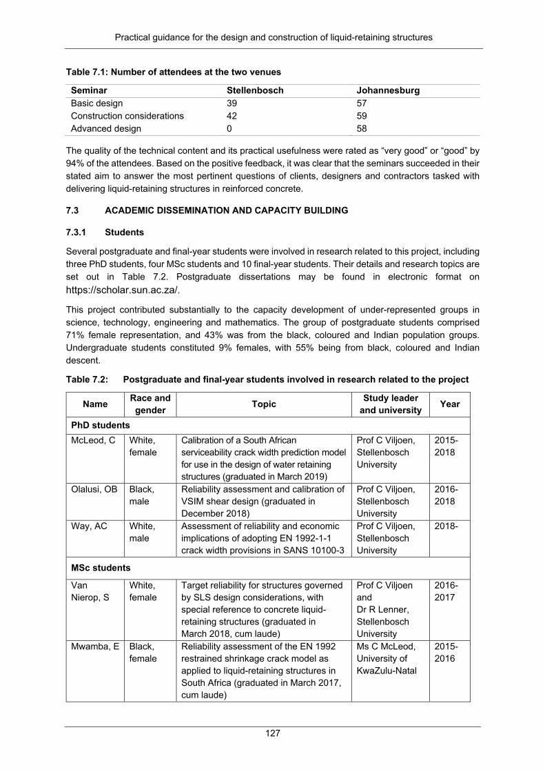
Practical guidance for the design and construction of liquid-retaining structures
127
Table 7.1: Number of attendees at the two venues
Seminar Stellenbosch Johannesburg Basic design 39 57 Construction considerations 42 59 Advanced design 0 58
The quality of the technical content and its practical usefulness were rated as “very good” or “good” by 94% of the attendees. Based on the positive feedback, it was clear that the seminars succeeded in their stated aim to answer the most pertinent questions of clients, designers and contractors tasked with delivering liquid-retaining structures in reinforced concrete.
7.3 ACADEMIC DISSEMINATION AND CAPACITY BUILDING
7.3.1 Students
Several postgraduate and final-year students were involved in research related to this project, including three PhD students, four MSc students and 10 final-year students. Their details and research topics are set out in Table 7.2. Postgraduate dissertations may be found in electronic format on https://scholar.sun.ac.za/.
This project contributed substantially to the capacity development of under-represented groups in science, technology, engineering and mathematics. The group of postgraduate students comprised 71% female representation, and 43% was from the black, coloured and Indian population groups. Undergraduate students constituted 9% females, with 55% being from black, coloured and Indian descent.
Table 7.2: Postgraduate and final-year students involved in research related to the project
Name Race and gender Topic Study leader
and university Year
PhD students McLeod, C
White, female
Calibration of a South African serviceability crack width prediction model for use in the design of water retaining structures (graduated in March 2019)
Prof C Viljoen, Stellenbosch University
2015- 2018
Olalusi, OB
Black, male
Reliability assessment and calibration of VSIM shear design (graduated in December 2018)
Prof C Viljoen, Stellenbosch University
2016-2018
Way, AC
White, male
Assessment of reliability and economic implications of adopting EN 1992-1-1 crack width provisions in SANS 10100-3
Prof C Viljoen, Stellenbosch University
2018-
MSc students
Van Nierop, S
White, female
Target reliability for structures governed by SLS design considerations, with special reference to concrete liquid-retaining structures (graduated in March 2018, cum laude)
Prof C Viljoen and Dr R Lenner, Stellenbosch University
2016-2017
Mwamba, E
Black, female
Reliability assessment of the EN 1992 restrained shrinkage crack model as applied to liquid-retaining structures in South Africa (graduated in March 2017, cum laude)
Ms C McLeod, University of KwaZulu-Natal
2015-2016

Practical guidance for the design and construction of liquid-retaining structures
128
Name Race and gender Topic Study leader
and university Year
Mans, R White, female
Investigation into the autogenous healing of small concrete crack widths, with an average surface width of 0.2 mm, specific to liquid-retaining structures in South Africa (graduated in March 2016)
Ms C McLeod, University of KwaZulu-Natal
2014- 2015
Mota, F
Indian, female
Effects of addition of fly ash on load-induced fracture in water-retaining structures (graduated in March 2019)
Dr C McLeod, University of KwaZulu-Natal
2017- 2018
Final-year projects
Sitole, T Black, male
Prediction of heat of hydration values for South African concretes
Dr C Viljoen, Stellenbosch University
2016
Wienand, QA
White, male
Prediction of heat of hydration values for South African concretes
Dr C Viljoen, Stellenbosch University
2016
Reed, KW Colouredmale
Tender specifications for liquid-retaining structures
Dr C Viljoen, Stellenbosch University
2016
Kirsten, FJDL
White, male
Adaptation to South African conditions of EN 1992-1-1 provisions for crack control
Prof C Viljoen, Stellenbosch University
2017
Govender, T White, male
Economic implications of updated T1 design values for South Africa
Prof C Viljoen, Stellenbosch University
2017
De Villiers, AJ
White, male
A guide to tender specifications for the construction of liquid-retaining concrete structures
Prof C Viljoen, Stellenbosch University
2017
Jack, M Black, female
Shrinkage characteristics of pump mix concrete for liquid-retaining structures
Prof C Viljoen, Stellenbosch University
2019
Reddy, J Indian, male
Cracking in reinforced concrete structures due to combined flexure and tension: a comparison of crack models applied to South African conditions
Ms C McLeod, University of KwaZulu-Natal
2015
Sokhulu, B Black, male
Investigation into the autogenous healing of SAP-containing concrete of 200 μm crack width
Ms C McLeod, University of KwaZulu-Natal
2016
Draper, W White, male
Reliability assessment of the EN 1992 flexural tension load-induced crack model in the context of liquid-retaining structures in South Africa
Ms C McLeod, University of KwaZulu-Natal
2017
Munsamy, R Indian, male
Investigation into a suitable target level of reliability for load-induced cracking in the serviceability limit state for reinforced concrete water-retaining structures
D. C McLeod, University of KwaZulu-Natal
2018

Practical guidance for the design and construction of liquid-retaining structures
129
7.3.2 Staff development
Five staff members from Stellenbosch University and the University of KwaZulu-Natal are involved in the project, either through direct participation, including student supervision, or through indirect participation, combined with participation in standards development committees. These are Prof Celeste Viljoen, Prof Johan Retief, Dr Christina McLeod, Dr Nico de Koker and Ms Esther Mwamba. The development of specialisation among these staff members was facilitated through this project. Again, the project contributed meaningfully to the capacity development of under-represented groups in science, technology, engineering and mathematics, with developed staff being 60% female and 20% black.
7.3.3 Attendance of international conferences and research publications
The transfer of the research results generated by students (See Section 7.3.1) on this project was disseminated to other postgraduate students and staff members in half-hour lectures that are regularly scheduled at Stellenbosch University. The results of final-year projects were disseminated via oral and poster presentations in addition to their written reports. Postgraduate theses can be accessed on SUNscholar at https://scholar.sun.ac.za.
Researchers and students active on the project generated conference papers and journal publications that were disseminated in scholarly peer-reviewed proceedings and ISI-listed journals.
Journal papers submitted and published since project inception are listed below:
• LENNER R, VAN NIEROP S and VILJOEN C (2018) A comparative study of target reliability index derivation for reinforced concrete structures governed by serviceability limit state. Structural Concrete. https://doi.org/10.1002/suco.201800202.
• OLALUSI OB and VILJOEN C (2019) Model uncertainties and bias in shear strength predictions of slender stirrup reinforced concrete beams. Structural Concrete. https://doi.org/10.1002/suco.201800273.
• OLALUSI OB and VILJOEN C (2019) Assessment of simplified and advanced models for shear resistance prediction of stirrup reinforced concrete beams. Engineering Structures 186 96–109. https://doi.org/10.1016/j.engstruct.2019.01.130.
• MCLEOD CH and VILJOEN C (2019) Quantification of crack width prediction model uncertainty in reinforced concrete under flexural loading. Structural Concrete (in press).
• OLALUSI OB and VILJOEN C (2019) Assessment of reliability of EN 1992-1-1 VSIM shear design provisions for stirrup failure. Structural Concrete (submitted).
Conference papers published and presented since project inception are listed below:
• VAN NIEROP S, VILJOEN C and LENNER R (2017) Target reliability of concrete structures governed by serviceability limit state design. In: International Probabilistic Workshop (IPW), Dresden, Germany.
• McLEOD CM, VILJOEN C and RETIEF JV (2017) Determining model uncertainty associated with concrete crack models for members in flexure. In: International Probabilistic Workshop (IPW), Dresden, Germany.
• McLEOD CM, VILJOEN C and RETIEF JV (2017). Determining model uncertainty associated with concrete crack models for members in tension. In: International Probabilistic Workshop (IPW), Dresden, Germany.
• OLALUSI OB and VILJOEN C (2017) Towards effective general probabilistic model representation for shear resistance. In: The 12th International Conference on Structural Safety and Reliability (ICOSSAR), Vienna, Austria.

Practical guidance for the design and construction of liquid-retaining structures
130
• REYNOLDS S and VILJOEN C (2016) Evaluation of life safety criteria for South African dams. In: Symposium of the International Committee on Large Dams (ICOLD), Johannesburg, South Africa.
• McLEOD CH, VILJOEN C and RETIEF JV (2016) Quantification of model uncertainty of EN1992 crack width prediction model. In: The 6th International Conference on Structural Engineering, Mechanics and Computation, Cape Town, South Africa.
• MWAMBA E and McLEOD CH (2016) Investigation of the reliability of the Eurocode 2 model for early age cracking of liquid retaining structures in South Africa. In: The 6th International Conference on Structural Engineering, Mechanics and Computation, Cape Town, South Africa.
The academic rigour required to publish in peer-reviewed ISI-listed journals and deliver papers at international conferences also facilitates capacity building. Provision was made for the attendance of conferences during the course of the project. Ms C McLeod (a member of the research team, University of KwaZulu-Natal staff member and Stellenbosch University PhD student) and Ms S van Nierop (MEng student) attended the International Probabilistic Workshop in Dresden in September 2017, where they presented their research findings to the broader research community.

Practical guidance for the design and construction of liquid-retaining structures
131
CHAPTER 8: FRAMEWORK FOR FUTURE INITIATIVES
8.1 INTRODUCTION
Water storage and reticulation infrastructure form a key part of municipal service delivery. The continued functioning of these assets represents a critical component of assuring public health, food security and economic activity. This is especially true for a water-scarce country such as South Africa, with its legacy of relatively advanced water and sanitation infrastructure.
Water and sanitation infrastructure plays a key role in advancing South Africa’s efforts to address poverty and inequality, as asserted by a number of the Sustainable Development Goals (United Nations, 2015), notably that of ensuring the availability of clean water and sanitation. However, this advantage will be lost unless the level of maintenance of these assets is not improved.
Estimates of global infrastructure needs and the associated capital requirements, including those emphasising the global south (Dobbs et al., 2013; Holmgren et al., 2016), tend to focus on the delivery of the initial product and neglect the extent to which continued operation is critically reliant on frequent and skilled maintenance. All infrastructure ages and degrades, and must be maintained and repaired to ensure that the assets continue to function as required. As a rule, adequate infrastructure maintenance implies prolonged expenditure with little visible return from the perspective of the voting public, who do not always appreciate the scale of development represented by potable water flowing from a tap.
It is often pointed out that short-term savings that arise from reduced emphasis on maintenance result in an aggravated repair expense burden in the medium and long term (Van Zyl, 2014; SAICE, 2017; DPW, 2007). Challenges associated with infrastructure deterioration will only expand in the coming years. Global infrastructure development surged during the second half of the 20th century, with the result that numerous systems are now well into their design lifetimes, and in many cases require extensive maintenance and repair to ensure that they continue to function. This challenge is further exacerbated by the combination of growing urban populations and intensifying extremes in weather conditions associated with climate change.
Municipalities and water regulatory authorities are most dependent on these infrastructure systems when they are also most strained: during periods of drought, and/or as a measure against large-scale flooding. Poorly managed and maintained water storage and reticulation infrastructure, which is unable to endure the demands of a critical period, represents a serious hazard in its own right.
The socioeconomic reach of South African water and sanitation infrastructure has increased notably as part of its effort to improve basic service delivery to previously disadvantaged communities. A side effect of this expansion has been that municipalities responsible for the completed assets do not always have the financial basis or necessary skills to adequately operate and maintain them beyond a very limited scope (Donaldson, 2006; WRC, 2015; McDonald & Fell, 2016).
Maintenance requires technical expertise covering the spectrum from professional engineers to specialised artisans. In its infrastructure report card for South Africa, SAICE (2017) highlighted the severe lack of technically trained and skilled individuals who can perform meaningful and sustainable infrastructure maintenance. Its report points out that most South African municipalities do not have an experienced engineer on their staff, with some even lacking any engineering expertise at all.
An important step in ensuring that our heritage of water storage and reticulation infrastructure is maintained is therefore to facilitate the continued dissemination of critical technical knowledge to the artisans and technicians responsible for the daily operation of these systems. At the same time, the education of civil and mechanical engineers, with an emphasis on maintenance (and their meaningful employment by municipalities), would ensure that new and existing infrastructure assets are maintained in a manner that is optimal in the long term.

Practical guidance for the design and construction of liquid-retaining structures
132
The technical details of water and sanitation infrastructure maintenance is well documented in both the academic and institutional literature. Notably, in the South African context, Van Zyl (2014) compiled an informative handbook detailing the possible failures that can be experienced by water reticulation infrastructure, as well as the associated maintenance measures necessary for continued operation. Similarly, WRC (2009) documents guidelines for the maintenance of water treatment plants, and Boyd and Mbelu (2009) document guidelines for monitoring wastewater treatment plants.
This document considers water and sanitation infrastructure maintenance, specifically from a civil engineering perspective. This limited scope necessarily excludes the important roles of human resources, financial management, accountability and stakeholder input. The following sections explore the primary elements of the water and sanitation infrastructure system, where maintenance is important. They also emphasise the value of performing continued monitoring and maintenance, and explore how training can be effectively accomplished. This chapter concludes with a discussion of problems that could benefit from further research work.
8.2 SOURCES OF FAILURE IN WATER AND SANITATION INFRASTRUCTURE
The infrastructure associated with water and sanitation spans very large physical and geographical ranges of scale and complexity. The following are included in the mix:
• Water-retaining structures, ranging from large dams to municipal reservoirs • Pipe networks, which are responsible for water reticulation and distribution • Sewerage networks that connect households to treatment works • Wastewater treatment works in themselves • Pumping plant and valves responsible for regulating pressure and flow through these various systems
The inherent complexity of these subsystems poses two challenges that maintenance has to meet. Firstly, it requires specialised expertise, drawing from a broad range of technical fields, including structural, hydraulic, mechanical, electrical, biochemical and process engineering. Secondly, breakdowns in one subsystem almost always affect other parts, so that overarching insight that covers all these fields and all the subsystems is necessary.
Broadly speaking, breakdowns and failures in these systems take the form of the following:
• Operational failures due to mechanical plant breakdowns or interruptions in electricity supply • Leaks and bursts in the water and sanitation reticulation networks • Long-term material decay and loss of structural integrity of the various retaining structures
To highlight the importance of maintenance, the following sections will consider the financial and environmental implications of maintenance through a number of example studies.
8.2.1 Operational failures in mechanical plants
Most water reticulation networks require a large number of pumps to ensure that flow rates, volumes and pressures in the system are maintained. In addition, most wastewater treatment plants in South Africa rely on motorised actuators to accelerate the aeration and biological breakdown of pathogens and biological waste.
The breakdown of a water reticulation pumping station not only implies an interruption of the delivery of water to municipal reservoirs, but can also result in the loss of hydraulic integrity and water quality (Van Zyl, 2014), in some cases, causing permanent damage to reticulation infrastructure.

Practical guidance for the design and construction of liquid-retaining structures
133
Similarly, sewerage will become congested following the breakdown of sewage pumping equipment, potentially causing spillage of hazardous wastewater. Without functioning actuators in wastewater treatment works, anaerobic conditions develop in the activated sludge tanks and effluent. Partially or completely untreated wastewater will thus leave the plant.
Insufficient, inadequate or even incompetent maintenance is prevalent in South African wastewater treatment plants. The Mail and Guardian reports that less than 10% of our treatment plants release clean water, with dysfunctional equipment identified as the main culprit (Kings, 2017).
The long-term environmental and public health impact of these statistics is difficult to evaluate, although it is no doubt extreme. However, the Mail and Guardian report provides an appreciation of the fiscal implications: emergency repair is routinely performed, with a single intervention consuming as much as 10% of the value of building a completely new treatment plant. With the necessary skills and training, preventative maintenance could have been provided at a fraction of the cost, and with none of the collateral environmental damage.
8.2.2 Reticulation losses
Differences are always measured between the volume of water delivered into a reticulation system, and the metered volume used by the end users. The difference arises from a combination of theft, leakages (real losses) and metering errors (apparent losses).
Leakages and bursts can be directly attributed to network operation and maintenance. Historically, leaks have, in the past, been difficult to locate because pipes are buried – even when the presence of a leak is evident. However, a number of strategies now exist to minimise the loss from leaks in the network, and to locate and fix the leaks when they form (Hamilton and Charalambous, 2013; Farley, 2001; GIZ, 2011; Puust et al., 2010). Mitigating strategies include improved pipe joint materials and strategic pressure reduction.
In reticulation systems where infrastructure is well maintained and theft is negligible, the total loss can be as low as about 7%, and systems with little or no maintenance only deliver about 50% of their intake volume (GIZ, 2011). In response to the looming supply crisis posed by the ongoing drought in the Western Cape, the City of Cape Town managed to bring the loss percentage in its reticulation network down to 17%, a significant achievement when the figure is compared to the national average of 36% (City of Cape Town, 2018).
The immediate value of saving an additional 20% of the distributed water is apparent in the context of a situation where a city is faced with having less than 100 days’ water supply remaining. The associated economic cost in terms of delayed and relocated investment is also severe, and has a longer-term impact than the duration of the drought itself.
However, the economic benefits of a 20% reduction in water loss volumes are just as significant in the absence of a water availability crisis. Given the non-drought daily water use of the City of Cape Town (800 Mℓ/d), and the cost of untreated water from a storage dam such as the Berg River Dam or the Theewaterskloof Dam (R5/Kℓ), a sustained 20% reduction in water loss volumes implies an accumulated financial saving equivalent to the construction cost of the Berg River Dam (R3.4 billion) within less than 20 years (Figure 8.1).
These savings illustrate the long-term value municipalities can derive from active loss reduction programmes. Of course, such an endeavour requires additional labour expenditure and the regular training of technical and maintenance staff, covering the spectrum from artisan to managerial level.

Practical guidance for the design and construction of liquid-retaining structures
134
Figure 8.1: Present value of accumulated savings resulting from sustained reductions of 5 to 20% in water loss volumes, calculated using consumption figures relevant to the City of Cape Town, and assuming a discount rate of 5%. The estimated replacement value of the Berg River Dam (adjusted to 2019 values) is shown for comparison.
8.2.3 Loss of integrity in retaining structures
Large and medium-sized dams often not only serve as a means of short-term water storage, but also as risk management tools, as they can temper the effects of severe flooding and extended periods of drought. However, there have been a number of incidents during the past 100 years where the actual or imminent failure of a large dam has turned such structures into severe hazards in their own right. In a number of these cases, the primary factor responsible for the problem was a lack of adequate monitoring and maintenance.
Large and medium-sized dams face two main factors, which degrade their long-term reliability and serviceability. Firstly, a loss of structural stability due to eroding or degrading the foundation support, and secondly, the deterioration of the wall material itself, resulting in a loss of structural integrity.
Large dams are subject to significant pressure from the depth of water they contain, and rely on foundations of significant resistance capacity for support. Should the foundation lose its ability to dissipate stresses from the dam wall, deformation and even failure of the wall could result.
Two examples of this hazard have emerged during the past five years. The first example, which is directly relevant to the southern African economy, affected the wall of the Kariba Dam. Completed in 1959, water from the spillway had progressively eroded the basaltic riverbed directly downstream of the wall, carving out a cavity 90 m deep and threatening the stability of the dam wall itself (Darbourn, 2015). It is estimated that the necessary intervention repairs will take about five to seven years to complete and will amount to around US$294 million (R4.2 billion) (African News Agency, 2016).
The second example occurred at Oroville Dam in California in February 2017, which forms a reservoir with a capacity of 4,360,000 Mℓ (comparable to the 5,340,000 Mℓ capacity of Gariep Dam). Following heavy rainfall, the main spillway failed in shear, sideways erosion threatened the main dam and mitigating measures resulted in unsafe erosion below the ungated emergency weir. This prompted authorities to evacuate some 188,000 people living downstream (France et al., 2018; Hollins et al., 2018). The rehabilitation and repair project was completed early in 2019 at an estimated cost of US$940 million (R13.4 billion), a value that does not include the cost of emergency response measures at the dam during the crisis (Californa Department of Water Resources, 2018). Cracking and deterioration of the spillway had been identified and documented prior to the event, but was not deemed serious enough to warrant intervention (France et al., 2018; Hollins et al., 2018).

Practical guidance for the design and construction of liquid-retaining structures
135
Degradation of the wall material itself also represents a threat to the structural stability and integrity of the dam. Internal erosion due to piping in earth dams is a well-known hazard (Terzaghi, 1943), while alkali-silica reaction (ASR) in concrete induces the swelling of the bulk material, resulting in the warping or cracking of concrete dams. The ASR has led to extensive damage to a number of dams in South Africa (Pourbehi, 2018), while there have also been reports of damage to dams in the Zambezi-Kafue system (Campbell et al., 2000). At the Fontana Dam in North Carolina, ASR-induced swelling stresses have been successfully managed via a long-term maintenance programme, which has been ongoing since its identification in the 1970s (Tennessee Valley Authority, 2017).
8.3 NEED FOR MAINTENANCE AWARENESS AND TRAINING
8.3.1 Skills needs for maintenance
In its infrastructure report card for South Africa, SAICE (2017) highlighted the lack of technically trained and skilled individuals in South African municipalities as the single-most critical factor hindering meaningful and sustainable water and sanitation infrastructure maintenance. The basic technical details of maintenance practice for water and sanitation infrastructure are well documented (for example, Van Zyl, 2014), but without engineers and technicians, a municipal authority cannot benefit from these guidelines.
The scope of skills needed can be understood in the context of the range of complexity involved in maintenance practice:
• Reactive maintenance, which is essentially to fix a component when it breaks: Depending on the nature of the problem, high-level input might be needed (if only in the form of a policy directive) to ensure that replaced parts or materials are compatible with the overall system and do not hinder future repairs. Examples include replacing parts in a broken-down pump or fixing a newly formed burst pipe.
• Proactive maintenance, where possible failure modes are known and anticipated, and which are avoided by regular monitoring of the system: Examples include locating and fixing leaking pipes, servicing pumping equipment, or monitoring the ASR-induced deformation of dam walls.
• Explorative maintenance, which is aimed at unknown or unanticipated failure modes: This requires understanding of the system as a whole and looking for unusual and unexpected changes over time. For example, occasional monitoring of the plunge pool at Kariba Dam might have revealed erosion well before its effect became a major hazard.
As a general trend, reactive maintenance mostly requires basic skill levels, as it does not involve new procedures or design solutions to be developed. Artisans can complete the task, in some cases aided by technicians. Engineering oversight is needed in a strategic capacity.
Proactive maintenance would require greater skill and training, as subtle early signs of deterioration that are present in monitoring data have to be identified and interpreted. Familiarity with the monitoring technique, as well as the infrastructure asset, is therefore necessary, which requires technicians, aided by technologists and, in some cases, engineers.
Explorative maintenance is uncommon and difficult to ascribe to a specific skill level. Long-term, sustained familiarity with an asset is important, although a fundamental grasp of its technical intricacies may also be helpful.
The benefit of having a workforce with a solid technical foundation, focused on the maintenance necessary to sustain acceptable levels of service delivery and performance, is therefore clear. Frequent spending on emergency intervention is not sustainable – it is an expense that could be used for the education, training and employment of engineers and technicians who can contribute to the prevention of asset breakdowns, thus increasing the quality of service delivery and stimulating job creation. With foresight and the correct educational resources, the quality of infrastructure can be elevated and sustained at levels that are affordable to the taxpayer and encourage future investment.

Practical guidance for the design and construction of liquid-retaining structures
136
8.3.2 Proposed training programme
South Africa urgently needs to scale up its municipalities’ infrastructure maintenance awareness and knowledge base. An ideal solution to the problem of insufficient technical expertise would be to incentivise municipal managers to employ more engineers, technologists and technicians, and to equip these professionals with maintenance expertise via postgraduate training at the various tertiary institutions. The funding and manpower for such an endeavour exists, as is evident from the large sums currently being spent on emergency interventions and the difficulty many recent graduates experience finding employment in the engineering sector. Such a solution would need to cater for the skills requirements of both reactive and proactive maintenance, depending on the candidate’s existing technical expertise and the sophistication of the municipality’s infrastructure.
In support (and anticipation) of this programme, a series of video-based training courses, which document the principles of infrastructure design and maintenance, could be compiled and distributed to municipalities. The contents of these videos should draw on the handbooks and guidelines already assembled by the WRC and the Department of Water and Sanitation (Van Zyl, 2014; Boyd and Mbelu, 2009; WRC, 2009), which emphasise theoretical and practical questions according to the target audience. Following completion of the series, trainees should have an improved appreciation of the value of maintenance, as well as a grasp of how to address maintenance-related problems with the assets for which they are responsible.
As part of the postgraduate training programme, students would contribute to expanding the body of knowledge associated with the maintenance of water and sanitation infrastructure. Some of the most pressing research questions associated with civil engineering are as follows:
• Designing infrastructure for low maintenance requirements. Many components of the existing design of water and sanitation infrastructure were developed in first-world countries, where sustained, skilled maintenance could be reasonably assumed. Implementing these designs in regions where such an expectation is unrealistic implies the need to explore low maintenance design alternatives.
• Designing optimal infrastructure maintenance programmes. Taking the information from increased (even automated) monitoring systems into account, combined with low maintenance designs, it is necessary to explore the optimal maintenance strategy from the perspective of minimising long-term risk.
• Assessing infrastructure health and anticipating breakdowns. This includes the development of more accessible monitoring systems, such as leak detection and localisation methods, and structural health monitoring techniques. Such a strategy would involve the analysis and interpretation of large data sets collected via a variety of sensors, and incorporating this information into a database that reflects the overall state of the system.
• Anticipating hazards associated with new types of water supply infrastructure. As traditional reservoir-borne water sources become insufficient, cities have started to explore alternative means of accessing potable water, including groundwater extraction, the re-use of wastewater and desalination. Each new source will be associated with new environmental and technical hazards, including unique maintenance challenges. These need to be identified and potential solutions explored.
• Rehabilitation and repair of concrete retaining structures. The deterioration of concrete dam walls due to alkali-silica reaction and reinforcement corrosion poses a large risk to water-retaining structures. Contributions can be made to the early identification of these modes of decay, as well as in developing economical and sustainable means of intervention.

Practical guidance for the design and construction of liquid-retaining structures
137
8.4 CONCLUSIONS
This framework for future initiatives identifies the optimal operation and maintenance of liquid-retaining and reticulation structures as critical to ensure that our legacy of water storage and reticulation infrastructure remains available and functional to serve our growing population.
Operational failures of mechanical plants in treatment works lead to health risks and environmental damage, which may be prevented, with proper maintenance, at a fraction of the cost of emergency intervention measures. Likewise, the long-term value municipalities can derive from active water loss reduction programmes is shown to be substantial. Efficient monitoring and maintenance regimes will, in turn, meaningfully reduce the risks associated with the loss of integrity in retaining structures.
In its infrastructure report card for South Africa, SAICE (2017) highlighted the lack of technically trained and skilled individuals in South African municipalities as the single-most critical factor that hinders meaningful and sustainable water and sanitation infrastructure maintenance.
The continued dissemination of critical technical knowledge to the artisans and technicians who are responsible for the daily operation of these systems is therefore important. At the same time, the education of civil and mechanical engineers, with an emphasis on maintenance (and their meaningful employment by municipalities), would ensure that new and existing infrastructure assets are maintained in a manner that is optimal in the long term. With foresight and the correct educational resources, the quality of infrastructure can be elevated and sustained at levels that are affordable to the taxpayer and encourage future investment.
As future initiatives, we propose online training videos, based on documented maintenance strategies, and targeting municipal technical staff. The contents of these videos should draw on the handbooks and guidelines already assembled by the WRC and the Department of Water and Sanitation (Van Zyl, 2014; Boyd and Mbelu, 2009; WRC, 2009), which emphasise theoretical and practical questions according to the target audience.
Future research contributions should support optimal maintenance initiatives. Possible topics were identified and could include the following
• Designing infrastructure for low-maintenance requirements • Designing optimal infrastructure maintenance programmes • Assessing infrastructure health and anticipating breakdowns using monitoring and data analysis • The rehabilitation and repair of concrete retaining structures, including economical and sustainable
means of intervention for alkali-silica reaction and reinforcement corrosion • Anticipating hazards associated with new types of water supply infrastructure

Practical guidance for the design and construction of liquid-retaining structures
138
CHAPTER 9: CONCLUSIONS
The WRC project K5/2514/1 succeeded in its main aims, which were as follows:
• Develop a complementary suite of documentation to aid the design, specification and construction of liquid-retaining structures
• Extend the research basis for future revisions of SANS 10100-3 • Contribute to training and capacity building through seminars and academic activities • Provide a framework for future initiatives
Three guideline documents were developed to cover the design, specification and construction of liquid-retaining structures in reinforced concrete. This contribution may be particularly helpful to small or medium-sized organisations, where in-house experience, specifically with liquid-retaining structures, may be limited:
• The design guide to the analysis and design of liquid-retaining structures, including example calculations to the requirements of SANS 10100-3.
• The guide on tender specifications extends the scope of SANS 2100 CC1 to be generally applicable to the construction of liquid-retaining structures and for it to be readily modified to make provision for particular liquid-retaining structure projects.
• The constructions guideline for site personnel and design engineers focuses on construction practices that are required to achieve the additional requirements of durability and leak tightness for liquid-retaining structures.
The research basis for future revisions of SANS 10100-3 was extended by a careful assessment of crack width prediction models in terms of their fundamental assumptions and accuracy when compared to experimental results. Together with an assessment of leakage rates and self-healing as a function of crack widths, practical recommendations could be made for models and crack limits to be considered for adoption in SANS 10100-3. Design values were derived for T1 (heat of hydration) and T2 (seasonal temperature variation) to be used in design for estimating early-age and long-term thermal cracking, respectively, based on local data regarding South African concretes and climate.
Dissemination seminars were presented in Stellenbosch and Johannesburg as a series of three one-day seminars. These covered basic design, construction considerations, and the advanced design of liquid-retaining structures. These were well attended by all relevant stakeholders, ranging from client organisations and water authorities, professional design engineers and technicians, to the construction industry and specialist companies serving the industry. The combined attendance amounted to 255 man-days, and participant feedback on the technical content was particularly positive.
The project contributed significantly to capacity building through the involvement of 16 students, four academics and several industry participants. In this regard, financial support was aimed at facilitating student training and research, including conference attendance. The project supported three PhD students and four MEng students, producing research that resulted in five ISI-listed journal publications and seven peer-reviewed conference publications.
In terms of further future revisions and the development of SANS 10100-3, some issues still require proper calibration and characterisation, not only on a national level, but on an international platform as well, mostly concerning the establishment of rational design procedures for liquid-retaining structures based on the principles of structural reliability. Further characterisation of material models to local data is warranted, particularly concerning information on the shrinkage characteristics of pump mix concrete, the strength evolution of concrete that is exposed to different curing regimes, and the heat evolution of concretes with binder extended by Corex slag.

Practical guidance for the design and construction of liquid-retaining structures
139
A framework for future initiatives identified the main sources of failure in water and sanitation infrastructure. The optimal operation and maintenance of these structures are recognised as critical to ensure that our infrastructure remains available and functional to serve our growing population. Training initiatives are proposed based on documented maintenance strategies that are aimed at municipal staff and engineering graduates, emphasising theoretical and practical questions according to the target audience. Research contributions to support optimal maintenance initiatives are identified.

Practical guidance for the design and construction of liquid-retaining structures
140
CHAPTER 10: RECOMMENDATIONS FOR FUTURE WORK
10.1 OPTIMAL MAINTENANCE OF EXISTING WATER AND SANITATION INFRASTRUCTURE
Chapter 8 identifies the need to facilitate the optimal maintenance of existing liquid-retaining structure infrastructure through targeted training and research. Suggestions for future initiatives to that end are detailed in Chapter 8.
10.2 CONTINUED REVISION AND UPDATING OF SANS 10100-3
There remains scope for the future revision and updating of SANS 10100-3. Some issues still require proper calibration and characterisation, not only on a national level, but also internationally, mostly concerning the establishment of rational design procedures for liquid-retaining structures based on the principles of structural reliability. The further characterisation of material models to local data is warranted, as noted in Table 10.1. Addressing these research needs is a long-term goal, which will facilitate future updates and revisions of SANS 10100-3.
Table 10.1: Some research issues relating to liquid-retaining structures in the South African context
Research title or issue Status Calibration of hydraulic loads {𝜸𝜸𝑭𝑭,𝝍𝝍} for liquid-retaining structures according to SANS requirements
Working Group SANS 10100-3 recommended values.
Investigate the reliability of the crack control procedures Some progress has been made through the PhD work of McLeod (2019) and Way (ongoing).
Seismic loading requirements and a study to establish if this is relevant for a region with NGPA = 1.0 to 1.5 g.
This aspect was partially investigated through an MSc study by Ms T Fourie.
Study of ULS and SLS combination the schemes and performance of liquid-retaining structures
Some progress has been made through the MEng work of Van Nierop (2018).
Investigation of the effect of stress in serviceability situations due to choices made for ULS
No progress
Splitting tensile tests performed to study the influence of aggregate type, binder type and curing
No progress
Influence of curing regimes on material properties, with special consideration for the pre-cast industry (heat treatment or steam curing as opposed to moist or wet curing)
No progress
Model reliability studies and calibration to define concrete models for E-modulus, tensile strength and creep and shrinkage prediction models
Some progress was made on the shrinkage of pump mix concrete through the BEng final-year project of Jack (2019).
Confirmation of heat of hydration (T1) values for South African Corex slag
Chapter 2 of this report made initial recommendations based on existing experimental work (Alexander)

Practical guidance for the design and construction of liquid-retaining structures
141
REFERENCES
AMERICAN CONCRETE INSTITUTE (1999) ACI 305R-99: Hot weather concreting. American Concrete Institute, Detroit, MI, USA.
AMERICAN CONCRETE INSTITUTE (2001) ACI 350-01: Requirements for environmental engineering concrete structures. American Concrete Institute, Detroit, MI, USA.
AMERICAN CONCRETE INSTITUTE (1997) ACI 373R-97: Design and construction of circular prestressed concrete structures with circumferential tendons. American Concrete Institute, Detroit, MI, USA.
AMERICAN CONCRETE INSTITUTE (1990) ACI 504R-90: Guide to sealing joints in concrete structures. American Concrete Institute, Detroit, MI, USA.
AFRICAN NEWS AGENCY (2016) Lake Kariba dam wall structural rehabilitation to commence in February 2017. Engineering News 7 October 2016.
ALEXANDER MG, JAUFEERALLY H and MACKECHNIE JR (2003) Structural and durability properties of concrete made with Corex slag. Research Monograph No. 6, Civil and Environmental Engineering, University of Witwatersrand, Johannesburg, South Africa.
ALLEN AH (1983) Autogenous healing. In: Seminar on design of concrete water retaining structures to BS 5337, Division of Hydraulic and Water Engineering of SAICE in association with the Concrete Society of South Africa.
AMERICAN WATER WORKS ASSOCIATION (2002) C 652:2002: Disinfection of water storage facilities. American Water Works Association, Denver, CO, USA.
ANCHOR RD (1981) Design of liquid retaining concrete structures, Wiley, London, UK.
ANSON M and ROWLINSON PM (1988) Early-age strain and temperature measurements in concrete
tank walls, Magazine of Concrete Research 40(145) 216–226.
ARYA C and OFORI-DARKO FK (1996) Influence of crack frequency on reinforcement corrosion in concrete. Cement and Concrete Research 26 (3) 345–353.
ATKINSON, R (2013) Crack width limits, Advanced seminar on the design of liquid retaining structures, Stellenbosch University, Stellenbosch, South Africa.
BAKER EH, KOVALEVSKY L and RISH FL (1972) Structural analysis of shells, McGraw-Hill, New York, NY, USA.
BALÁZS GL (1993) Cracking analysis based on slip and bond stresses. ACI Materials Journal 90 (4).
BALÁZS GL, BISCH P, BOROSNYOI A, BURDET O, BURNS C, CERONI F, CERVENKA V, CHIORINO MA, DEBERNARDI P, ECKFELDT L, EL‐BADRY M, FEHLING E, FOSTER SJ, GHALI A, GRIBNIAK V, GUIGLIA M, KAKLAUSKAS G, LARK RJ, LENKEI P, LORRAIN M, MARI A, OZBOLT J, PECCE M, CALDENTEY AP, TALIANO M, TKALCIC D, TORRENTI JM, TORRES L, TOUTLEMONDE F, UEDA T, VITEK JL and VRABLIK L (2013) Design for SLS according to fib Model Code 2010. Structural Concrete 14 (2). BALLIM Y and GRAHAM PC (2004a) A numerical model for predicting time-temperature profiles in concrete structures due to the heat of hydration of cementitious materials. Research Monograph No. 8, Civil and Environmental Engineering, University of Witwatersrand, Johannesburg, South Africa.

Practical guidance for the design and construction of liquid-retaining structures
142
BALLIM Y and GRAHAM PC (2004b) Early-age thermal characteristics of clinker cements in relation to microstructure and composition: Implications for temperature development in large concrete elements. Cement and Concrete Composites 26 417–426.
BALLIM Y (2004) Temperature rise in mass concrete elements – model development and experimental verification using concrete at Katse Dam. Journal of the South African Institute of Civil Engineering 46 (1) 9–14.
BAMFORTH PB (2007) CIRIA C660: Early age thermal crack control in concrete. Thomas Telford, London, UK.
BARNARDO-VILJOEN C, MENSAH KK, RETIEF JV, WIUM JA and VAN ZIJL GPAG (2014) Background to the Draft SA National Standard for the Design of Water Retaining Structures. Concrete/Beton 138 10–19.
BEEBY AW (1978) Cracking – what are crack width limits for. The Concrete Society, Cement and Concrete Association, Concrete 12 (7) 31–33.
BEEBY AW (1979) Prediction of crack widths in hardened concrete. Struct Engineering 57A (1) 9–17.
BEEBY AW (1990) Fixings in cracked concrete – the probability of coincident occurrence and likely crack width. TN 136, CIRIA, London, UK.
BEUSHAUZEN H, ALEXANDER M and BALLIM Y (2012) Early age properties, strength development and heat of hydration of concrete containing various South African slags at different replacement ratios. Construction and Building Materials 29 533–540.
BHATT P, MCGINLEY TJ and CHOO BS (2006) Reinforced concrete: Design theory and examples, 3rd ed., Taylor & Francis, London, UK.
BILLINGTON DP (1965) Thin shell concrete structures, McGraw- Hill, New York, NY, USA.
BOYD LA and MBELU AM (2009) Guideline for the inspection of wastewater treatment works. WRC Report No. TT 375/08, Water Research Commision, Pretoria, South Africa.
BRITISH ADHESIVES AND SEALANTS ASSOCIATION (BASA) (2001) Guide to the British Standard BS 6213 – Selection of construction sealants. BASA, London, UK.
BRITISH STANDARDS INSTITUTE (1985) BS 8110:1985: Structural use of concrete: Part 2: Code of practice for special circumstances. British Standards Institution, London, UK.
BRITISH STANDARDS INSTITUTE (1987) BS 8007:1987: Code of practice for design of concrete structures for retaining aqueous liquids. British Standards Institution, London, UK.
BRITISH STANDARDS INSTITUTE (1997) BS 8110:1997: Structural use of concrete: Part 1: Code of practice for design and construction. British Standards Institution, London, UK.
BRITISH STANDARDS INSTITUTE (2000) BS 6213:2000: Selection of construction sealants. British Standards Institute, London, UK.
BRITISH STANDARDS INSTITUTE (2010) BS EN 196-9:2010: Methods of testing cement. Heat of hydration. Semi-adiabatic method. British Standards Institute, London, UK.

Practical guidance for the design and construction of liquid-retaining structures
143
BURNS C (2012) Serviceability analysis of reinforced concrete based on the tension chord model. Working paper IBK Bericht No. 342, Institute of Structural Engineering, Swiss Federal Institute of Technology, Zurich, Switzerland.
BUSSELL MN and CATHER R (1995) CIRIA 146: Design and construction of joints in concrete structures. Thomas Telford, London, UK.
CALDENTEY AP (2017) Proposal of new crack width formulas in the Eurocode 2, background, experiments, etc. In: Nordic mini-seminar: Crack width calculation methods for large concrete structures, Oslo, Norway.
CALDENTEY AP, CORRES H, IRIBARREN JP and SOTO AG (2013) Cracking of RC members revisited: Influence of cover, φ/ρ s, ef and stirrup spacing – an experimental and theoretical study. Structural Concrete 14 (1).
CALIFORNA DEPARTMENT OF WATER RESOURCES (2018) Oroville spillways construction and cost estimate update. https://water.ca.gov/News/News-Releases/2018/Sept-18/Oroville-Spillways-Construction-and-Cost-Estimate-Update.
CAMPBELL FL, JOURDAN M, MCCLESKY T, PHILIPS M, ROLAND W AND SHOULDERS A (2000) Report of the US Army Corps of Engineers African Response Team. US Army Corps of Engineers African Response Team, Washington, DC, USA.
CEMENT AND CONCRETE INSTITUTE (2009) Fulton’s concrete technology, 9th ed., Cement and Concrete Institute, Midrand, South Africa.
CITY OF CAPE TOWN (2018) Water Outlook 2018 Report. Department of Water and Sanitation, City of Cape Town, Cape Town, South Africa.
CONCRETE SOCIETY (2004) In situ strength of concrete – An investigation into the relationship between core strength and the standard cube strength, Working party of the Concrete Society, Project Report No 3, BCA, Camberley, Surrey, ISBN 0 94669 186 X.
CRANK J (1975) Numerical methods. In: The mathematics of diffusion, 2nd ed., Oxford Science Publications, Oxford, UK.
CLAUSER C and HUENGES E (1995) Thermal conductivity of rocks and minerals. In: AHRENS TJ, Rock physics and phase relations – a handbook of physical constants, American Geophysical Union, Washington, DC, USA.
CLEAR CA (2016) Sustainable feature: Cement type | Early age properties, BRMCA British Ready-Mixed Concrete Association, Concrete Today 12-14.
DARBOURN K (2015) Risk research report: Impact of the failure of the Kariba Dam. The Institute of Risk Management of South Africa, Johannesburg, South Africa.
DARWIN D, MANNING DG, HOGNESTAD E, BEEBY AW, RICE PF and GHOWRWAL AQ (1985) Debate: Crack width, cover, and corrosion. Concrete International 7 (5) 20–35.
DEPARTMENT OF PUBLIC WORKS (DPW) (2007) The National Infrastructure Maintenance Strategy. DPW, Pretoria, South Africa.

Practical guidance for the design and construction of liquid-retaining structures
144
DE SCHUTTER G (1999) Hydration and temperature development of concrete made with blast-furnace slag cement. Cement and Concrete Research 29 (1) 143–149.
DHIR R, PAINE KA and ZHENG L (2006) Design data for use where low heat cements are used. DTI Research Contract No. 39/680, CC2257, Report No. CTU2704, University of Dundee, Dundee, Scotland.
DOBBS R, POHL H, LIN D-Y, MISCHKE J, GAREMO N, HEXTER J, MATZINGER S, PALTER R and NANAVATTY R (2013) Infrastructure productivity: How to save $1 trillion a year, McKinsey Global Institute, London, UK.
DONALDSON S (2006) All fall down – existing assets abandoned in race to meet targets. The Water Wheel March/April 32–37.
EDVARDSEN C (1999) Water permeability and autogenous healing of cracks in concrete. ACI Materials Journal 96 M56 448–454.
EUROPEAN COMMITTEE FOR STANDARDISATION (2004) EN 1992-1-1:2004: Design of concrete structures – general rules and rules for buildings. European Committee for Standardisation (CEN), Brussels, Belgium.
EUROPEAN COMMITTEE FOR STANDARDISATION (2006) EN 1992-3:2006: Eurocode 2: Design of concrete structures – Part 3: Liquid retaining and containment structures. European Committee for Standardisation (CEN), Brussels, Belguim.
FAN SC, AW KM, TAN YM (2004) Peak temperature rise for early-age concrete under tropical climate condition, Journal of the Institution of Engineers, Singapore 44(1) 1-10.
FARLEY M (2001) Leakage management and control: A best practice training manual. World Health Organization, Geneva, Switzerland.
FRANCE JW, IRFAN AA, DICKSON PA, FALVEY HT, RIGBEY SJ and TROJANOWSKI J (2018) Independent forensic team report, Oroville Dam spillway incident.
FRENCH JW, MACK D, SHAFER R and MOORE K (n.d.) Clarifying the application of subgrade modulus in structural analysis and design. In: 8th National Conference on Earthquake Engineering, San Francisco, CA, USA.
FORTH PF and MARTIN AJ (2014) Design of liquid retaining concrete structures, Whittles Publishing, Dunbeath, UK.
GEOCOMMUNITY (2016) GIS data for South Africa. http://data.geocomm.com/catalog.
GERMAN DEVELOPMENT CORPORATION (GIZ) (2011) Guidelines for water loss reduction: A focus on pressure management. Deutsche Gesellschaft für Internationale Zusammenarbeit (GIZ), Bonn, Germany.
GHALI A (1979) Circular storage tanks and silos, E & FN Spon, London, UK.
GIBBON GJ, BALLIM Y and GRIEVE GRH (1997) A low-cost, computer-controlled adiabatic calorimeter for determining the heat of hydration of concrete. ASTM Journal of Testing and Evaluation 25 (2) 261–266.

Practical guidance for the design and construction of liquid-retaining structures
145
GRAHAM PC, BALLIM Y and KAZIRUKANYO JB (2011) Effectiveness of the fineness of two South African Portland cements for controlling early-age temperature development in concrete. Journal of the South African Institute of Civil Engineering 53 (1) 39–45.
HAMILTON S and CHARALAMBOUS B (2013) Leak detection: Technology and implementation, IWA Publishing, London, UK.
HOHMAN R (2011) Joint sealing in water resistant concrete structures. Fraunhofer IRB Verlag, Stuttgart, Germany.
HOLLINS LX, EISENBERG D and SEAGER TP (2018) Risk and resilience at the Oroville Dam. Infrastructures 3 (4). DOI: 10.3390/infrastructures3040049.
HOLMGREN KE, LI H, VERSTRAETE W and CORNEL P (2016) State of the art compendium report on resource recovery from water. International Water Association, London, UK.
HORNBOSTEL K and GEIKER M (2017) Influence of cracking on reinforcement corrosion. In: Nordic mini-seminar: Crack width calculation methods for large concrete structures, Oslo, Norway.
HOUSTON J and FERGUSON P (1972) Corrosion of reinforcing steel embedded in structural concrete in Research Report 112-1F. Center for Highway Research, University of Texas at Austin, Austin TX, USA.
INSTITUTION OF CIVIL ENGINEERS (2011) CESMM3:2011: Civil engineering standard method of measurement – South African edition. Institution of Civil Engineers, London.
INTERNATIONAL FEDERATION FOR STRUCTURAL CONCRETE (fib) (2013) The fib model code for concrete structures 2010. Ernst & Sohn, Berlin, Germany.
JACCOUD JP (1987) Armateur minimale pour le contrôle de la fissuration des structures en béton. PhD thesis. Ecole Polytechnique Fédérale de Lausanne (EPFL), Lausanne, Switzerland.
JONES A (2008) Eurocode 2 – design of concrete structures: Part 3. Liquid-retaining and containment structures. Dissemination of information workshop, Brussels, Belgium.
KINGS S (2017) 50 000 litres of sewage flow into SA's rivers every second. Mail & Guardian 21 July 2017.
KRUGER AC (2008) Climate of South Africa – surface temperature. South African Weather Service, Pretoria, South Africa.
KRUGER AC (2016) Personal communication.
KRUGER HG (2002) Crack width calculation to BS 8007 for combined flexure and direct tension. The Structural Engineer 80 (18) 18‒22.
KRUGER HG and ATKINSON RA (2005) Improved crack width calculation method to BS 8007 for combined flexure and direct tension. The Structural Engineer 83 (10) 18‒20.
LAPI M, ORLANDO P and SPINELLI A (2018) A review of literature and code formulations for cracking in R/C members. Structural Concrete 1–23.
LOHMEYER G (1984) Wasserdurchlässige Betonabauwerke - Gegenmassnahmen bei Durchfeuchtungen, Beton 34(2).
Practical guidance for the design and construction of liquid-retaining structures
146
MEICHSNER H (1992) Ueber die Selbstheilung von Trennrissen in Beton, Beton- und Stahlbetonbau 87(4).
MCDONALD A and FELL J (2016) Water sector risk governance: An implementation guide for South African water utilities. WRC Report No. TT 669/16, Water Research Commission, Pretoria, South Africa.
MCLEOD CH (2013) Investigation into cracking in reinforced concrete water retaining structures. MSc Eng dissertation, Stellenbosch University, Stellenbosch, South Africa.
MCLEOD CH (2019) Model uncertainty in the prediction of crack widths in reinforced concrete structures and reliability implications for liquid retaining structures. PhD dissertation, Stellenbosch University, Stellenbosch, South Africa.
NATIONAL READY MIXED CONCRETE ASSOCIATION (NRMCA) (2009) Concrete in oractice. CIP 42: Thermal cracking of concrete. NRMCA, Silver Spring, MD, USA.
NISHIYAMA H (1975) Experiments of steel corrosion due to cracking. In: 30th Annual Conference of the Japan Society of Civil Engineers.
OESTERLE RG (1997) The role of concrete cover in crack control criteria and corrosion protection. RD Serial No. 2054, Portland Cement Association, Skokie, IL, USA.
OTIENO MB, ALEXANDER MG and BEUSHAUSEN H-D (2010) Corrosion in cracked and uncracked concrete – influence of crack width, concrete quality and crack reopening. Magazine of Concrete Research 62 (6) 393–404.
PAINE KA, ZHENG L and DHIR RK (2005) Experimental study and modelling of heat evolution of blended cements. Advances in Cement Research 17 (5) 121–132.
PAINE KA, DHIR RK and ZHENG L (2006) Predicting early-age temperatures of blended-cement concréte. Proceedings of the Institution of Civil Engineers, Construction Materials 159 (4) 163–170.
PITKANEN P (1984) Prediction of temperature fields of massive concrete structures during hardening. Nordic Concrete Research 3 183–190.
PORTLAND CEMENT ASSOCIATION (n.d.) Circular concrete tanks without prestressing. Portland Cement Association, Skikie, IL, USA.
POURBEHI MS (2018) Numerical modelling of alkali silica reaction in concrete dams. PhD thesis, University of Stellenbosch, Stellenbosch, South Africa.
PRICE WF (2006) Production data provided by Lafarge Cement. Lafarge Cement UK, Oxon, UK.
PUUST R, KAPELAN Z, SAVIC DA and Koppel T (2010) A review of methods for leakage management in pipe networks. Urban Water Journal 7 25‒45.
RAMM W and BISCOPING M (1998) Autogenous healing and reinforcement corrosion of water-penetrated separation cracks in reinforced concrete. Nuclear Engineering and Design 179 (2) 191‒200.
REYNOLDS CE, STEEDMAN JC and THRELFALL AJ (2008) Reynolds's reinforced concrete designer's handbook, 11th ed., Taylor & Francis, London, UK.
ROSS AD and BRAY JW (1949) The prediction of temperatures in mass concrete by numerical computation. Magazine of Concrete Research 1 (1) 9–20.

Practical guidance for the design and construction of liquid-retaining structures
147
SAGÜÉS AA, KRANC SC, PRESUEL-MORENO F, REY D, TORRES-ACOSTA A and YAO L (2001) Corrosion forecasting for 75-year durability design of reinforced concrete. Final Report No. BA502 submitted to Florida Department of Transportation by University of South Florida, Tampa, FL.
SCHIESSL P and RAUPACH M (1997) Laboratory studies and calculations on the influence of crack width on chloride-induced corrosion of steel in concrete. ACI Materials Journal 94 (1) 56.
SCHIESSL P (1976) Zur frage der zulaessigen rissbreite und der erforderlichen betondeckung im stahlbetonbau unter besonderer beruecksichtigung der karbonatisierung des betons. Deutscher Ausschuss fuer Stahlbeton Heft 255, Ernst, Berlin, Germany.
SCHIESSL P and WOELFEL E (1986) Konstruktionsregeln zur beschränkung der rissbreite ‒ grundlage zur neufassung DIN 1045, Abschnitt 17.6. Beton- und Stahlbetonbau 81 (1) 8‒15.
SHAIKH FUA (2018) Effect of cracking on corrosion of steel in concrete. International Journal of Concrete Structures and Materials 12 3.
SOUTH AFRICAN BUREAU OF STANDARDS (1982) SANS 1200:1982: Standardized specification for civil engineering construction Section G: Concrete (structural). South African Bureau of Standards, Pretoria, South Africa.
SOUTH AFRICAN BUREAU OF STANDARDS (2007) SANS 2001:2007: Construction works Section CC1: Structural concrete. South African Bureau of Standards, Pretoria, South Africa.
SOUTH AFRICAN BUREAU OF STANDARDS (2013) SANS 50197-1:2013: Cement: Composition, specifications and conformity criteria for common cements. South African Bureau of Standards, Pretoria, South Africa.
SOUTH AFRICAN BUREAU OF STANDARDS (2015) SANS 10100-3. 2015: Design of concrete liquid retaining structures. SABS 98/02 Technical Committee Draft (unpublished). South African Bureau of Standards, Pretoria, South Africa.
SOUTH AFRICAN INSTITUTION OF CIVIL ENGINEERING (SAICE) (2017) 2017 Infrastructure Report Card for South Africa. South African Institution of Civil Engineering, Johannesburg, South Africa.
KRUGER AC (2002) Climate of South Africa. Surface winds, WS 43, South African Weather Service
SPOONER DC (1992) Computer model for temperature rise prediction in fresh concrete. TDH 51062. British Cement Association, CIRIA, Londen, UK.
TEAL OR (2016) Crack closure and enhanced autogenous healing of structural concrete using shape memory polymers. PhD thesis, School of Engineering, Cardiff University, Cardiff, Wales.
TENNESSEE VALLEY AUTHORITY (2017) Good medicine for Fontana Dam. https://www.tva.gov/Newsroom/Good-Medicine-for-Fontana-Dam.
TERZAGHI K (1943) Theoretical soil mechanics, John Wiley & Sons, New York, NY, USA.
TUUTTI K (1978) The corrosion of steel in concrete ‒ the effect of cracks in the concrete cover in CBI Forsk. Swedish Cement and Concrete Research Institute at the Institute of Technology, Stockholm, Sweden.
UNITED NATIONS (2015) Transforming our world: The 2030 Agenda for Sustainable Development. United Nations General Assembly, United Nations, New York, NY, USA.

Practical guidance for the design and construction of liquid-retaining structures
148
UNO PJ (1998) Plastic shrinkage cracking and evaporation formulas. ACI Materials Journal 95 (4) 365‒375
VAN NIEROP S (2016) Target reliability of concrete structures governed by serviceability limit state design. MEng dissertation, Stellenbosch University, Stellenbosch, South Africa.
VAN ZYL JE (2014) Introduction to operation and maintenance of water distribution systems. Water Research Commission, Pretoria South Africa.
VILJOEN C, MENSAH KK, RETIEF JV, WIUM JA and VAN ZIJL GPAG (2014) Background to the draft SA national standard for the design of water retaining structures. Concrete Beton, Journal of the Concrete Society of Southern Africa 138 10‒19.
VILJOEN C and RETIEF JV (2015) Design guidance on T1 and T2 for South African conditions and concretes. WRC Report No. WRC K5/2514/1, Water Research Commission, Pretoria, South Africa.
VILJOEN C (2013) Compilation of a South African National Standard for the design of liquid retaining structures. WRC Report No. 2154/1/15, Water Research Commission, Pretoria, South Africa.
WATER RESEARCH COMMISSION (WRC) (2009) Guidelines for the sustainable operation and maintenance of small water treatment plants. WRC Report No. TT 408/09, Water Research Commission, Pretoria, South Africa.
WATER RESEARCH COMMISSION (WRC) (2015) South Africa's water research, development, and innovation (RDI) roadmap: 2015‒2025. WRC Report No. 2305/1/15, Water Research Commission, Pretoria, South Africa.
WATER RESEARCH COMMISSION (WRC) (2017) K5/2145/1: Construction guideline for liquid retaining structures. Water Research Commission, Pretoria, South Africa.
WATERMEYER RB (2008) The adoption of CESMM3 as a standard method of measurement of civil engineering quantities in South Africa. Civil Engineering 16 (1) 18‒19.
WATERMEYER RB, LOMAS M, MACDONALD H, JACQUET A, GRIFFITHS A, BAIRD P and CULLEN M (2012) The changing landscape for civil engineering contracts: Moving on from SABS 1200. Civil Engineering 20 (1) 20‒25.
WATERMEYER RB (2016) Withdrawal of SANS 1200 and SANS 10120 as a South African National Standard. Civil Engineering March 31‒34.
WANG C and DILGER WH (1994) Prediction of temperature distribution in hardening concrete. In: SPRINGENSCHMID R, Thermal cracking in concrete at early ages, E & FN Spon, Londen, UK. International RILEM Symposium, Institute of Building Materials, Technical University of Munich, Munich, Germany.
WOOD RH (1981) Joints in sanitary engineering structures. Concrete International April 53‒56.
YACHIDA M (1987) Cracking and reinforcement corrosion in reinforced concrete bridges. Journal of Materails ‒ Concrete Structures and Pavements 6 (378) 195‒202.
YI S-T, HYAN T-Y and KIM J-K (2011) The effects of hydraulic pressure and crack width on water permeability of penetration crack-induced concrete. Journal of Construction and Building Structures 25 2576–2583.
ZARGHAMEE MS and HEGER FJ (1983) Buckling of thin concrete domes. ACI Journal Proceedings 80 (6) 487‒500.

Practical guidance for the design and construction of liquid-retaining structures
149
ZIARI A and KIANOUSH MR (2009a) Investigation of direct tension cracking and leakage in RC elements. Journal of Engineering Structures 31 406‒474.
ZIARI A and KIANOUSH MR (2009b) Investigation of flexural cracking and leakage in RC liquid containing structures. Journal of Engineering Structures 31 1056‒1067.
APPENDIX A: SPECIFICATION DATA FOR GENERIC LIQUID-RETAINING STRUCTURES
1 2 3 Clause number Specification data associated with SANS 2001 CC1 Considerations
Essential data 4.2.1.1 Cementitious binders shall be common cements that
comply with SANS 50197-1. All cement used in the works shall be Portland cement CEM II of strength class 42.5. Fly ash shall be of a consistent quality. In particular, it shall be tested for and shall conform with the following: a) The loss on ignitition shall not exceed 5% b) The percentage by mass retained on 45-micron
screen shall not exceed 12.5% Controlling heat of hydration: Corex slag shall not be used as cement extender unless it can be shown that the mix design adheres to design requirements in terms of its heat of hydration characteristics. For tanks containing sewage or where aggressive groundwater is present: sulphate-resisting concrete is required in accordance with the guidance provided in SANS 10100-2. Controlling ASR: The total alkali-content (Na2O-equivalent) of concrete shall be limited to 0.6%, taking into account the degree of reactivity of the aggregate. In this regard the recommendations in Cement and Concrete Technology (2009) shall be adhered to. Either use a blend of common cement that complies with SANS 50197-1 and cement extenders, or use selected common cements that comply with SANS 50197-1 such that at least 40% of GGBS or 20% of fly ash, by mass, of the binder is introduced in the mix. Where used as separate ingredients at the mixer, extenders shall comply with SANS 55167-1, SANS 50450-1 and SANS 50450-2 or SANS 50934-6, SANS 53263-1, SANS 53263-2, and SANS 50934-2.
Omit if default requirements shall apply. Amend if cementitious binders shall be limited to common cements or specify what shall apply. Refer to SANS 10100-2 for guidance on the selection of cementitious binders for sulphate-resisting concrete or where the combination of cement and aggregate might give rise to a harmful alkali-aggregate reaction.
4.2.2 Water shall comply with the requirements of SANS 51008. Water used for the mixing of concrete should not contain traces of sugar or other deleterious substances. Water for curing shall be of the same quality as the water that is used to produce concrete.
4.2.3.1 Aggregates shall comply with the following requirements:
Omit if default requirements shall apply.

Practical guidance for the design and construction of liquid-retaining structures
150
1 2 3 Clause number Specification data associated with SANS 2001 CC1 Considerations
Aggregates may be obtained from local sources subject to testing of their suitability by an approved reputable laboratory. Aggregates shall be tested periodicaly for reactivity according to Clause 4.2.3.5d. Aggregates shall comply with the following additional requirements: Add Clause 4.2.3.1 (c) to (e): (c) Aggregate absorption shall be less than 3%. (d) If aggregate absorption exceed 1.5%, the affected
stockpiles shall be treated by soaking with potable water to achieve the saturated surface dry state. Ensure that soaked stockpiles are adequately drained.
(e) Fine aggregate used for structural concrete shall have between 90 and 100% of particles passing a test sieve of nominal aperture 4.75 mm, between 75 and 100% passing 2.36 mm, between 60 and 90% passing 1.18 mm, between 40 and 60% passing 0.6 mm, between 20 and 40% passing 0.3 mm, between 10 and 20% passing 0.15 mm, and between 5 and 20% passing 0.075 mm.
Aggregates with low shrinkage, low thermal expansion and low risk for alkali-silica reaction are preferred. Design provision shall be adjusted if these cannot be obtained.
4.2.3.1 The nominal maximum size of coarse aggregate should not exceed: a) One-quarter of the minimum thickness of the concrete
cross section b) The specified cover over reinforcement. In elements with closely spaced reinforcement, the use of a nominal size of 9.5 or 13.2 mm should be considered.
Omit if default requirements shall apply.
4.2.3.4 4.7.10.11
Plums are permitted in plain concrete. The use of plums shall not be permitted in structural concrete
Omit if plums are not permitted in plain concrete.
4.2.3.5 The following tests are required: a) Drying shrinkage on fine and course aggregates b) Drying shrinkage of concrete c) Flakiness index of the stone d) Alkali-aggregate reaction Add to Clause 4.2.3.5 d) Alkali-aggregate tests may be omitted if the structure will not be exposed to sea spray and if the concrete is designed to have a total equivalent sodium oxide content of less than 1.8kg/m3, calculated according to the guidelines and examples in Cement and Concrete Technology (2009). Design calculations against ASR shall be submitted for review. Add Clause 4.2.3.5 e) The coefficient of thermal expansion of the concrete shall be less than [default 10] micro-strain.
These tests are required for liquid-retaining structures. Adjust test compliance limits if necessary. Ideally, the designer shall make design provision for the coefficient of thermal expansion relevant to the project. This may often be larger than the value of 10 micro-strain assumed here. The design value should be specified. Note: Values for different rock types are published in Cement and Concrete Technology (2009). The coefficient for the concrete is typically slightly higher than that of the rock type.
4.2.4 Admixtures are permitted, provided that the results of trial tests, which demonstrate their suitability, and the following are made available:
Omit if admixtures are not permitted. Adjust wording as required.

Practical guidance for the design and construction of liquid-retaining structures
151
1 2 3 Clause number Specification data associated with SANS 2001 CC1 Considerations
a) The trade name of the admixture, its source and the
manufacturer's recommended method of use. b) Typical dosages and possible detrimental effects of
underdosages and overdosages. c) Whether compounds likely to cause corrosion of the
reinforcement or deterioration of the concrete (such as those containing chloride, in any form, as an active ingredient) are present and, if so, the chloride content of admixtures, expressed as a mass fraction of chloride ions or expressed as an equivalent mass fraction of anhydrous calcium chloride.
d) The average expected air content of freshly mixed concrete containing an admixture that causes air to be entrained when the admixture is used at the manufacturer's recommended dosage.
(SANS 10100-2 requires that such information be furnished.) Concrete subject to freezing and thawing cycles shall be air entrained, in which case guidance may be sought from Table 4.2.2.4 in ACI 301.
4.2.6 The minimum grade of concrete shall be C29/35 MPa (cylinder strength / cube strength equivalents). The grade of concrete shall not exceed the specified grade by more than 5 MPa.
State grade if not shown in the construction drawings or specified elsewhere in the scope of work. Clause 4.3.1.3 of SANS 10100-3 requires a minimum grade of 35 MPa. Exceeding the specified grade may contribute to a high heat of hydration and related early-age thermal cracks. Adjust the limit if necessary according to the risk related to this aspect. Omit if hydration heat is addressed by performance-based mix design specification.
4.2.7 The material requirements for grout shall be as follows: In addition to Clause 4.2.7: Sand used for grouting shall have 100% of particles passing a test sieve of nominal aperture 9.5 mm, between 95 and 100% passing 4.75 mm, between 45 and 65% passing 1.18 mm, between 5 and 15% passing 0.3 mm, and between 0 and 5% passing 0.15 mm. For tendon grouting: Grout for water tank tendons shall contain admixtures that lower the water-cement ratio, improve flowability and minimise bleeding. Expansive characteristics may also be provided if desired. The grout, if providing expansion by the evolution of gas, should have 3 to 8% total expansion measured in a 500 mm height. An ad-hoc method for determining whether grout is satisfactory is to place the grout in a 25 to 75 mm diameter plexiglass cylinder 500 mm high ten minutes after mixing, cover to minimise evaporation and let it set. No visible bleeding should occur during the test. Epoxy used for injection into cracks, minor honeycombing, separated shotcrete covercoats or wet spots shall be a two-component, 100% solids, moisture-insensitive epoxy system. Grout used for crack repair and patching of ferrules, etc. shall contain an admixture that waterproofs by crystalisation (Xypex or similar approved) at a rate in accordance with the manufacturer’s recommendation.
State requirements if different to the default requirements.

Practical guidance for the design and construction of liquid-retaining structures
152
1 2 3 Clause number Specification data associated with SANS 2001 CC1 Considerations
4.2.8.2 The characteristic strength of the steel in the tendons shall be not less than …
State the characteristic strength of the tendons if not specified elsewhere in the scope of work.
4.2.11 Joint fillers, sealants, waterstops, bearings, and accessories shall comply with the following requirements: Addition to Clause 4.2.11.1 Sponge filler should be closed-cell neoprene or rubber capable of taking a head of 15 m of liquid concrete without absorbing grout and becoming hard. Waterstops should be composed of plastic or other suitable materials. Plastic waterstops of polyvinyl chloride are recommended. Splices should be made in accordance with the manufacturer's recommendations. Bearing pads should be composed of neoprene, natural rubber, polyvinyl chloride or other materials that have demonstrated acceptable performance under similar conditions and applications. Addition to Clause 4.2.11.2: Bond breaker shall be self-adhesive PVC tape with a width the same as the joint recess into which it is applied. Add Clause 4.2.11.4: Joint materials shall be stored and protected to avoid damage, degradation, distortion or contamination. The joint materials shall be resistant to ultraviolet light and to biological degradation. Add Clause 4.2.11.5 Waterstops shall be of the pattern and the material and widths scheduled and specified and shown on the drawings. They shall comply with the tolerances specified in Sub-clause 5.2. All intersections between waterstops shall be prepared by mitring and welding/vulcanising intersection pieces in the factory in accordance with the manufacturer’s instructions. Only straight lengths of waterstops may be field welded using the appropriate jigs and tools. Where required, waterstops shall have eyelets so that they may be tied securely to the adjacent reinforcement. “Rearguard”-type waterstops shall have flanges or cleats that grip effectively. Add Clause 4.2.11.6 Closed-cell expanded polyethylene fillers shall be precut to suit the application with a tear-out strip for forming the specified recess for the sealant. If so required, the fillers shall be glued into position with an approved epoxy glue. Add Clause 4.2.11.7 Bond breakers shall be self-adhesive PVC tape (or equal, approved material) with a width the same as the joint recess into which it is to be applied.
State requirements for joint fillers, sealants, waterstops, bearings and accessories if not specified elsewhere in the scope of work.

Practical guidance for the design and construction of liquid-retaining structures
153
1 2 3 Clause number Specification data associated with SANS 2001 CC1 Considerations
The primer, if required for the sealant, shall be fully compatible with the sealing compound that is to be used. The elastometric sealant shall be either a two-component polysulphide liquid polymer base complying with the requirements of SABS 110 or a polyethylene-based polyurethane “pouring grade” for horizontal or near horizontal joints or “gun grade” for vertical/overhead joints and joints steeper than 1 in 10 to horizontal. All elastomeric sealants shall comply with BS 4254 Type A1 and shall have a movement tolerance of 25%.
4.2.11.3 Backing material is … State backing requirements if default requirements shall not apply or where requirements are not specified elsewhere in the scope of work.
4.2.11.4 Steel cover plates shall comply with … Galvanizing of cover plates is required. Access ladders, ventilators, pipework and other metal items subject to alternate wetting and drying cycles shall be made of stainless steel.
State requirements for cover plates if steel is different to the default type and if galvanizing is required. Omit if galvanizing is not required or if requirements are specified elsewhere in the scope of work.
4.3.1.5 Earth cuts shall not be used as forms for vertical surfaces, except for the following: Concrete used in pipe trenches for encasement shall be cast directly against the side of the excavation. Concrete for thrust/anchor blocks shall be cast directly against the side of the excavation.
Omit if permitted.
4.3.1.6 Approval of the authority controlling the service is required before commencing the design of formwork over the road/ street/railway.
Omit if not a requirement or if requirement is specified elsewhere in the scope of work. Amend as necessary.
4.3.1.8 The formed surfaces shall be as follows: … State formed surface requirements in terms of Table 1 if not specified elsewhere in the scope of work.
4.3.1.8 State degree of accuracy for formed surfaces. Rough formwork: Degree of Accuracy III may be used on the outside faces where concrete is more than 500 mm below the final ground level. All concrete surfaces that will be exposed above the final ground levels shall have a smooth-special finish to a Degree of Accuracy I. The formwork used shall be high-grade, unblemished and regular in size. Formwork ties shall be placed in a regular pattern. The smooth-special finish shall be an off-shutter finish to the concrete such that no after treatment is required other than at the positions of formwork ties.
State degree of accuracy (default value is II).
4.3.1.8 The following special off-form surface finishes/exposed aggregate finishes are required: …
State requirements as necessary if not specified elsewhere in the scope of work (see Table 1).
4.3.2.1.4 The design and drawings for formwork and falsework shall be submitted for review.
Omit if not a requirement.
4.3.5.3 The thickness of mild-steel spiral-lock-formed void formers shall be as follows: … Void formers are not allowed
Omit if default thicknesses shall apply or if specified elsewhere in the scope of work. Void formers are not recommended for liquid-retaining structures to avoid associated risks of displacement of reinforcement due to flotation loads from bouyant void formers.

Practical guidance for the design and construction of liquid-retaining structures
154
1 2 3 Clause number Specification data associated with SANS 2001 CC1 Considerations
4.3.8.3 The falsework and supporting formwork on continuously reinforced concrete structures shall be removed as follows: …
Describe the manner in which falsework and supporting formwork shall be removed where the structure is constructed in stages.
4.3.8.4 The falsework and supporting formwork on pre-stressed concrete structures shall be removed after ...
Describe the manner in which the falsework and supporting formwork in pre-stressed structures shall be removed if not after the full pre-stressing force relating to the particular stage of construction has been applied.
4.4.1.3 Bars may be bent hot. Omit. Bars shall not be bent hot. 4.4.2.2 Welding of bars is permitted.
Omit Clause 4.4.2.2(b) Welding of bars is not permitted.
Omit if welding of bars is not permitted.
4.4.3.1 The cover shall be as follows:
Omit if default cover shall apply or if specified elsewhere in the scope of work. A minimum cover of 25 mm is required in accordance with Clause 4.4.1.2 of SANS 10100-3 (105), and SANS 51992-1-1 exposure class XC2 and structural class S4, which is less than the default here.
4.4.3.2 Rail and structural steel reinforcement shall not be used in liquid-retaining structures.
Omit if default cover shall apply or if specified elsewhere in the scope of work.
4.5.1 Fixtures to be embedded in the concrete shall be attached as follows: a) After casting of the concrete, all shuttering shall be
removed and the sides of the bolt holes and surface on which the machine base is to be placed shall be scabbled to remove all defective concrete laitance, dirt, oil, grease and loose material.
b) Upon completion of the positioning and alignment of
equipment, pockets and baseplates shall be grouted up by filling pockets and voids under the baseplates with an approved non-shrink grout.
c) Fixings shall be cast in or grouted into pockets or
installed by other means as specified on the drawings. d) Where anchor bolts are used, which are installed into
holes drilled into concrete or masonry, these shall be manufactured from stainless steel or a metal with a resistance to corrosion equal to that of grade 304 L stainless steel. The metal used for bolts shall be compatible with galvanised mild steel
e) Anchor bolts shall have minimum pull-out forces and
minimum ultimate lateral loads at least equal to those specified below:
Specified anchor size
Minimum pull-out
force (kN)
Minimum ultimate
lateral load (kN)
M6 M8 M10
10.35 13.70 19.44
7.60 11.15 15.95
State requirement, as necessary. Omit where requirements are specified elsewhere in the scope of work.

Practical guidance for the design and construction of liquid-retaining structures
155
1 2 3 Clause number Specification data associated with SANS 2001 CC1 Considerations
M12 M16 M20
31.85 50.45 60.50
26.90 45.80 71.20
f) Where entry holes for pipes/specials penetrate the walls,
these shall be concreted in with suitable watertight fittings. 4.6.2.1 The material and design of waterstops and their location in
the joints shall be as follows: Expansion and contraction joints shall be constructed using waterstops as detailed on drawings. Rearguard and centrebulb waterstops shall be PVC or rubber waterstops. Waterstops extruded from recycled material shall not be permitted. Waterproofing bandage shall comprise two elements: a) A 2 mm thick flexible polyolefin bandage (350 mm
wide for expansion joints and 200 mm wide for contraction joints)
b) A 1 x 50 mm stainless steel strip with polythene backing bond breaker to the details shown on the drawing
Prior to bandaging, concrete surfaces shall be scabbled with a mechanical scabbler and water jetted with a 120-bar water jet. The bandage shall be applied by coating the concrete and underside of the bandage with an epoxy adhesive. The stainless steel strip is first positioned over the joint and the bandage with epoxy adhesive placed over the stainless steel strip. All trapped air shall be eliminated by hand rolling the bandage until the epoxy is fully cured. All bandage joints shall be butt jointed and patched over.
State requirement, as necessary. Omit where requirements are specified elsewhere in the scope of work.
4.7.1.1 Prescribed-mix concrete is required. For liquid-retaining structures: Cement content shall be extended to comprise a minimum 25% fly ash or 35% ground granulated blast-furnace slag to control the heat of hydration. The extension shall be by mass of the total binder content.. Corex slag shall not be used as cement extender unless it can be shown that the mix design adheres to design requirements in terms of its heat of hydration characteristics. Any mix for use in the wall or floor of a water-retaining structure shall have a water-cement ratio not exceeding 0.5, shall contain not less than 325 kg cement per cubic metre of concrete and the proportions of the various aggregates shall be such as to produce a density of at least 2,400 kg/m3. The free water content (excluding aggregate absorption water) shall not exceed 190 litres/m3. Where, for whatever reason, 190 ℓ free water content is not achievable, suitability of the concrete for use will be decided by its ability to pass durability testing, in conjunction with the heat of hydration peak and rate minimised to acceptable levels – measured
Omit if strength concrete is required or the requirements for a prescribed mix are specified elsewhere in the scope of work.

Practical guidance for the design and construction of liquid-retaining structures
156
1 2 3 Clause number Specification data associated with SANS 2001 CC1 Considerations
against a reference concrete that conforms to all the recommended objectives. The concrete mix shall be designed in accordance to the guidelines and examples in Cement and Concrete Technology (2009), such that the total equivalent sodium oxide content of the concrete is sufficiently low to prevent the occurance of alkali-aggregate reaction, taking into account possible long-term exposure to sea spray. Design calculations to prove adequacy of the concrete mix against ASR shall be submitted for review.
4.7.1.2 The cementitious binder content for any class of concrete shall not exceed ….kg/m3 of concrete.
Omit if default value of 500 kg/m3 is not appropriate.
4.7.2.1 The slump of concrete shall be between 100 and 120 mm. The slump for pump mix concrete shall be between 120 and 150 mm. Slumps towards the high end of this range should be targeted if extended travelling times are expected, to allow for evaporation during transport and to prevent the need to revive workability at the point of discharge. The slump of each batch of concrete shall be taken and recorded directly before casting.
Omit if default slump values shall be used. The slump values specified here is in accordance with the recommendation of Clause 4.3.1.4 of SANS 10100-3, which exceeds the limits of Table 4 of SANS 2001 CC1.
4.7.3.2 4.7.10.15
Pumping of concrete is permitted. Omit if pumping is not permitted.
4.7.4.1 Efflorescence is not acceptable. The maximum chloride ion content shall be ...
Omit if default values shall be used or where requirements are specified elsewhere in the scope of work.
4.7.4.2 The total water‐soluble sulphate content of the concrete mix shall not exceed a mass faction of 4% of the cementitious binder content of the mix.
4.7.5.1 Concrete that has an air-dry density in the range 2,000 to 2,600 kg/m3 shall contain entrained air that conforms to the limits given in Table 6.
4.7.5.2 Concrete made to have an air-dry density that does not exceed 2,000 kg/m3 shall contain 6% ± 2% or 7% ± 2% total air.
Omit if not a requirement. Where required, select appropriate option depending on nominal maximum size of aggregate. For liquid-retaining structures: Concrete density less than 2,400 kg/m3 is not recommended. Air entrainment may be useful for concrete exposed to freeze-thaw cycles.
4.7.6.1 The mix proportions for the prescribed mix shall be as follows: …
State mix proportions where a prescribed mix is required. (SANS 2001 CC2 contains a generic prescribed mix). For liquid-retaining structures: If a prescribed mix is specified, the mix shall adhere to the requirements for high durability and low heat of hydration. See Clause 4.3.1.3 of SANS 10100-3 for guidance.
4.7.6.2 The coarse aggregate for the prescribed mix shall be sourced from …
State the source of coarse aggregate, if necessary.

Practical guidance for the design and construction of liquid-retaining structures
157
1 2 3 Clause number Specification data associated with SANS 2001 CC1 Considerations
For liquid-retaining structures: Prevention of alkali-silica reaction needs consideration. Aggregate with low coefficient of thermal expansion is preferred. Low shrinkage is preferred. See Clause 4.2.3.1.
4.7.8.2 Ready-mixed concrete shall not be permitted. or Ready-mixed concrete shall be mixed as follows: …
Omit if ready-mixed concrete in accordance with the requirements of SANS 878 shall be used.
4.7.10.10 The bridge deck may be cast in more than one pass. Omit if bridge deck shall be cast in one pass.
4.7.10.13 Concrete may be placed under water. Omit if concrete shall not be placed under water.
4.7.11.3 Concrete shall only be compacted by means of mechanical vibration.
4.7.12.1.1 Construction joints are required. or Construction joints shall not be formed at the following locations: … Each joint shall be formed as shown on the drawings, complete with shear key rebates, waffle formwork, V-feature, waterstops, “Flexcell” or equal, approved joint filler, dowel bars and their PVC tubes, etc. as indicated. Construction joints in walls and footings: Walls of circular reservoirs conventionally reinforced shall not have vertical joints unless indicated otherwise. Walls of post-tensioned reservoirs shall not have horizontal joints unless indicated otherwise. All construction joints in reservoir walls and footing shall be cast with hydrophilic waterstops, which shall be securely fixed to the centre of the section and shall be kept dry (including from rain) until casting. Construction joints in roof slabs: Construction joints in the roof slab are permitted. The proposed position of these joints shall be submitted to the engineer for comment. These joints shall be cast against a vertical shutter leaving a 15 mm deep by 20 mm wide recess, which is sealed with one part polysulphide sealer on completion. The method of application shall be according to the manufacturer’s specification. Construction joints in floor: Construction joints in the floor are only permitted where indicated on the drawings. All construction joints in the floor shall be cast with hydrophilic waterstops, which shall be securely fixed to the centre of the section and shall be kept dry until casting.
State requirements, if any, or if not specified elsewhere in the scope of work.
4.7.12.1.4 Proprietary bonding compounds between old and new concrete may be used.
Omit if proprietary bonding compounds shall not be used between old and new concrete.

Practical guidance for the design and construction of liquid-retaining structures
158
1 2 3 Clause number Specification data associated with SANS 2001 CC1 Considerations
Epoxy used for increasing the bond between hardened concrete and plastic concrete should be a two-component, 100% solids, moisture-insensitive epoxy adhesive. The bonding agent should produce a bond strength not less than 10 MPa 14 days after the plastic concrete is placed.
4.7.12.4 Joints shall be sealed with … 4.7.12.4.6 The elastomeric sealant shall be either a two-component polysulphide liquid polymer base complying with the requirements of SABS 110 or a polyethylene based polyurethane "pouring grade" for horizontal or near horizontal joints or "gun grade" for vertical/overhead joints and joints steeper than 1 in 10 to the horizontal. All elastomeric sealants shall comply with BS 6213 and BS 4254 Type A1 and shall have a movement tolerance of 25%. The primer, if required for the sealant, shall be fully compatible with the sealing compound that is to be used.
State joint sealing requirements, if any, or if not specified elsewhere in the scope of work.
4.7.15.1 Exposed surfaces of concrete not finished against forms shall have the following surface finishes: …
State surface finish if not specified elsewhere in scope of work, or where a different finish to the default finish is required.
4.7.15.2 Non-skid surfaces are required in the following areas:… Omit if non-skid finishes are not required or where requirements for non-skid finishes are specified elsewhere in the scope of work.
4.7.16 The following structures shall be watertight: … The floors, walls and roof of reservoirs shall be considered to be watertight concrete.
Omit if requirement is specified elsewhere in the scope of work.
4.8.6.1 Samples of precast concrete units that have architectural finishes shall be prepared.
Omit if such samples of concrete are not required to establish a standard for quality and colour before full-scale production is commenced.
4.8.6.2.3 A mosaic finish is required. Omit if not a requirement or requirement is specified elsewhere in the scope of work.
4.9.2.1.1 Solvents may be used for cleaning. or Solvents may not be used for cleaning of the inside of structures that will retain potable water.
Omit if solvents for cleaning are not permitted at all.
4.9.2.5.1 The pre-stressing force diagram is contained in sketch … Indicate where pre-stressing diagram shall be found, if not in the construction drawings.
4.9.2.5.8 The order of loading and the magnitude of the load for each component of the tendon shall be as follows: …
State requirements, if not specified elsewhere in the scope of work.
4.9.3.1.2 Bleeding tests and grouting trials are required. 4.9.4.2 Preliminary tests shall be undertaken on the proposed
encasement materials. Omit if preliminary tests shall not be undertaken on the proposed encasement materials.
4.9.4.3 The protection and bonding of the tendons shall be effected within ... days after final tensioning of the tendon(s).
State time period if default value shall not be used.
4.10.1.3 The position of lifting and supporting points, the method of lifting, and the type of equipment and transport used shall be as follows: …
Omit if requirements are specified elsewhere in the scope of work.
4.10.2 The method of assembly and erection shall be as follows: … Omit if requirements are specified elsewhere in the scope of work.
4.10.4.1 The design requirements for the structural connections shall be follows: …
Omit if requirements are specified elsewhere in the scope of work.

Practical guidance for the design and construction of liquid-retaining structures
159
1 2 3 Clause number Specification data associated with SANS 2001 CC1 Considerations
5.1.1.7 The test results from a ready-mix production facility, as part of its quality control system, shall be used.
Omit if the test results from a ready-mix production facility, as part of its quality control system, shall not be used.
5.1.1.8 The test for the percentage of alkali-aggregate shall be as follows: Aggregate shall be subjected to petrographic examination according to the RILEM test method TC 106-1 to determine the potential for akali reactivity of the aggregate.
State requirements for test if required. Suitable test is required for water-retaining structures as moist conditons increase the risk of ASR.
5.1.2.3 The test results may be assessed statistically. Omit if the test results shall not be assessed statistically.
5.1.3.2 Sets of samples of concrete shall be taken as follows: At least two sets of samples of concrete shall be taken from each day's casting and from at least every 20 m3 (or less) of concrete of each grade placed. For each sample taken, the position in the structure shall be recorded where the batch represented by that sample is placed. For each casting the contractor shall keep records of: a) Time elapsed between mixing and casting of concrete b) Time elapsed between batches cast c) Slump test results of each ready-mix truck d) Delivery note for each ready-mix truck
Specify additional requirements as necessary.
5.1.4.1 The following load tests shall be carried out: … Omit if not a requirement. State requirements.
5.1.4.2.1 The maximum deflection is ... State deflection requirements for non-destructive (service) test.
5.1.4.3 The ultimate design load is ... State ultimate design load for destructive (ultimate) test.
5.1.4.4 The following special tests are required: A site test shall be carried out for each grouting procedure and each grouting gang to be used. The tests shall be carried out on a dummy bedplate similar in configuration to that which is to be grouted, but not exceeding 1 m2 in area unless otherwise ordered. When the dummy bedplate is dismantled, the underside shall show a minimum grout contact area of 80% with reasonably even distribution of the grout over the surface grouted except that, in the case of expanding grout, the minimum grout contact area shall be 95%. The test shall show evidence of good workmanship and materials.
State requirements for special tests.
5.1.5.1.1 The particular test requirements for pre-stresssed structures are …
State particular test requirements for pre-stressed structures.
5.1.5.4 and Table 10
The acceptance criteria for Class 3 pre-stressed structures in extreme exposure conditions are...
State acceptance criteria.
5.1.5.4(a) The class of the pre-stressed structure is … State the class of the pre-stressed structure.
5.1.5.4(c) The deflection measured immediately after application of the test load for deflection shall not exceed ...
State deflection limits, if applicable.
5.1.6.1 ... shall be used as the liquid for test purposes. The stabili ing period is ... days. The total permissible drop in level is ...
State requirements, as relevant. State type of liquid if other than water. State the stabilising period – the default values of 7 days for a maximum design crack width of 0.1 mm and 21 days for a crack width

Practical guidance for the design and construction of liquid-retaining structures
160
1 2 3 Clause number Specification data associated with SANS 2001 CC1 Considerations
of 0.2 mm is in accordance with Clause 2.9.3.2 of SANS 10100-3. State total permissible drop – the default values of 10 mm or 1/500th the average water depth is in accordance with Clause 2.9.3.2 of SANS 10100-3.
5.2.1.1 The degree of accuracy is ... Reinforcement shall be placed to Degree of Accuracy I. All fittings and embedded items shall be placed to Degree of Accuracy I. The specified permissible deviation (mm) in Table 11, “cover to reinforcement” shall be 0, +5 for specified cover up to and including 35 mm, and shall be 0, +10 for specified cover larger than 35 mm, for all degrees of accuracy.
State degree of accuracy required, if not specified elsewhere in the scope of work.
1 2 3
Clause number
Specification data associated with this part of SANS 2001 Considerations
Variations 4.2.1.3 Addition to Clause 4.2.1.3:
Any cement that contains lumps that cannot easily be crumbled to powder between the fingers may not be used.
Cement stored too long or not protected from moisture.
4.2.3.3 Omit Clause 4.2.3.3. Breeze concrete is not allowed.
4.2.3.6 d Addition to Clause 4.2.3.6: Aggregate shall be stored such that: d) Solar heat gain is prevented.
4.3.2.2 4.3.3.4 4.3.3.5 4.4.2.7 4.7.10.17 4.7.21
Omit clauses 4.3.2.2, 4.3.3.4, 4.3.3.5, 4.4.27, 4.7.10.17 and 4.7.21. Sliding formwork is not allowed for liquid-retaining structures.
This is because of the potential for horizontal cold joints, honeycombing and subsequent leakage.
4.3.3.2 Addition to Clause 4.3.3.2: Cast-in ties shall be positively anchored to prevent rotation when loosening formwork.
4.3.3.3 Addition to Clause 4.3.3.3: Open ferrules will not be allowed. On removal of the removable ends of the cast-in ties, ferrules shall be grouted as per Clause 4.7.19.2 with a grout that adheres to Clause 4.2.7
4.3.5. Omit Clause 4.3.5: Void formers shall not be allowed for liquid-retaining structures.
Risk of floating, dislocating rebar to which it is attached.

Practical guidance for the design and construction of liquid-retaining structures
161
1 2 3 Clause number
Specification data associated with this part of SANS 2001 Considerations
4.4.2.3 In addition to Clause 4.4.2.3 Only cementitious, proprietary spacers should be used, preferably the circular variety. The concrete grade shall be the same as for the element in which it is used. Plastic spacers shall not be used. Spacers shall be placed at bar intersections and spaced at not less than 50 d, where d is the diameter of the bar that is supported. Spacers shall be spaced in staggered rows. Spacers must be wetted before placing of concrete to prevent local dry spots in the concrete.
4.4.3.2 Omit Clause 4.4.3.2. Structural steelwork shall not be used as reinforcement.
Large section size likely equates to crack widths in excess of what is acceptable.
4.7.1.1 Addition to Clause 4.7.1.1: All concrete used for water-retaining structures shall contain an admixture that waterproofs by crystalisation (Xypex or similar approved) at a rate in accordance with the manufacturer’s recommendation. Compatibility of the admixtures in the concrete shall be verified.
This is an optional clause with significant cost implication – to be discussed with the client. These products are usually not guaranteed to work for crack widths over 0.2 mm (i.e. proper design should negate the need for this admixture). However, significant uncertainty is associated with existing crack width prediction models and this admixture will reduce the risk of leakage in case of crack widths exceeding 0.2 mm and up to 1.0 mm.
4.7.10.11 Omit Clause 4.7.10.11: Plums are not allowed.
4.7.14.1 Addition to Clause 4.7.14.1: If concrete is to be cast during times of high ambient temperature, the area of the pour shall be shaded before and during concreting and the placed concrete and its formwork shall be shaded from the time of mixing until 30 hours after placing.
Peak heat of hydration is typically reached within 30 hours of casting.
5.1.6.3 Addition to Clause 5.1.6.3: Any necessary remedial treatment of the concrete should, where practicable, be carried out from the liquid face.
Improves effectiveness in providing watertightness.
5.2.8; Table 13
For pre-stressing in reservoir walls, the values in Table 13 shall be interpreted as follows: The depth of member d is the wall thickness; the width of beam shall be taken as 1,000 mm; permitted vertical and horizontal tolerances shall be accordingly swopped.
1 2 3
Clause number
Specification data associated with this part of SANS 2001 Considerations
Additions 4.3.3.6 Add Clause 4.3.3.6:
The use of sleeves for formwork ties through the walls of liquid-retaining structures will not be permitted.

Practical guidance for the design and construction of liquid-retaining structures
162
1 2 3 Clause number
Specification data associated with this part of SANS 2001 Considerations
4.6.2.3 Add Cause 4.6.2.3: Waterstops shall be held in the formwork so as to prevent air pockets forming underneath them. Special precautions shall be taken to ensure that all flexible waterstops are in perfect contact with well-compacted, void-free concrete.
4.7.14.8 Add Clause 4.7.14.8: Steel formwork shall be shaded before, during and for at least three days after concreting, except for cold weather concreting.
To reduce solar heat gain and associated thermal cracking risk, particularly for thin wall sections.
4.7.1.3 Add Clause 4.7.1.3: Condensed silica fume shall be limited to a maximum of 5% by mass of the cementitious material.
To prevent workability problems.
4.7.5.3 Add Clause 4.7.5.3: Acceptance criteria for concrete durability indices shall be as follows:
Acceptance category Description / limit Water sorptivity (mm/h 0.5)
Oxygen permeability, log scale
Concrete manufactured, cured and evaluated in a laboratory
<10 >9.6
Full acceptance of in-situ cast concrete
<10 >9.6
Conditional acceptance of in-situ cast concrete (with remedial measures)
10-15 8.75-9.6
Rejection >15 <8.75
Adjust acceptance limits if needed. The values provided for laboratory concrete are in accordance with SANS 10100-3. In-situ values are less stringent, based on expert judgment.
4.7.5.4 Add Clause 4.7.5.4: Concrete of structures exposed to very severe conditions shall adhere to the following chloride conductivity limits: (values may be interpolated based on the composition of the cementitious content in the mix design)
Environmental class
70:30 CEM I: FA
50:50 CEM I: GGBS
50:50 CEM I: GGCS
90:10 CEM I:
SF XS1 (exposed to airborne salt)
2.50 2.80 3.50 0.80
XS 2a (permanently submerged in salt water)
2.15 2.30 2.90 0.50
XS 2b, XS 3a (XS 2a + tidal splash and spray zones)
1.10 1.35 1.60 0.35
XS 3B (XS 3a + exposed to abrasion)
0.90 1.05 1.30 0.25
State chloride conductivity acceptance limits. Only to be required where the structure will be exposed to highly aggressive environments.

Practical guidance for the design and construction of liquid-retaining structures
163
1 2 3 Clause number
Specification data associated with this part of SANS 2001 Considerations
4.7.8.4.7 Add Clause 4.7.8.4.7: The specified depth of no-fines concrete shall be cast in one pour. Between 24 and 48 hours after the no-fines layer has been laid, it shall be covered with a 1:4 cement: sand mortar layer 15 mm thick. The mix shall be comparatively dry to ensure that it does not penetrate and block the cavities in the no-fines concrete. The surface shall be steel floated to form a plane surface. The mortar skim shall be cured in the same manner as concrete for a period of not less than 2 days.
4.7.10.18 Add Clause 4.7.10.18: After vibration, the concrete shall be spaded in corners, in angles and against forms to release air bubbles that may have been trapped in these positions.
4.7.11.9 Add Clause 4.7.11.9: Particular care shall be taken to compact the concrete around water stops, edges, etc. using adequate approved tools and experienced, reliable workmen.
4.7.11.10 Add Clause 4.7.11.10: The top 600 mm of walls shall be vibrated again after completing a wall section. Such revibration should be done while the concrete is still in the green state, i.e. the concrete must close the hole where the poker is extracted. The exact timing of such revibrating needs to be determined by experimenting and could be in the order of one or two hours after completing a wall section.
To eliminate voids that may have formed below horizontal reinforcement bars.
4.7.11.11 Add Clause 4.7.11.11” A 25 to 50 mm layer of neat cement grout shall be placed at the base of cast-in-place walls to help prevent voids in this critical area. The grout should have about the same water-cement ratio as the concrete that is used in the wall, and a consistency of thick paint.
4.7.11.12 Add Clause 4.7.11.12: A 600 mm thick layer of concrete with 9 mm maximum size aggregate shall be placed at the bases of walls to help prevent voids in congested areas including around waterstops.
4.7.12.2.4 Add Clause 4.7.12.2.4: Any non-designated joints shall be identical to designated joints, as shown on the drawings, which would be used in similar positions and perform the same function.
4.7.12.2.5 Add Clause 4.7.12.2.5: Expansion and contraction joints shall be formed true to line in smooth formwork. The edge of joints, exposed to view in the finished structure, shall be formed with suitable beads to provide a straight edge true to line level.
4.7.12.2.6 Add Clause 4.7.12.2.6: All joint surfaces shall be thoroughly cleaned of all accretions of concrete or other foreign matter by scraping or other approved means.

Practical guidance for the design and construction of liquid-retaining structures
164
1 2 3 Clause number
Specification data associated with this part of SANS 2001 Considerations
4.7.12.2.7 Add Clause 4.7.12.2.7: Joint filler shall be fixed to the first cast of concrete with an approved adhesive as specified on the drawings and according to the manufacturer’s method of application.
4.7.12.2.8 Add Clause 4.7.12.2.8: Joints in the filler shall be neatly butted so as to exclude mortar from the joint. Edges of filler strip against waterstops, concrete formwork, projections, etc., shall also be closely fitted to exclude mortar, so that there is no resistance (other than the compression of the filler) to the expansion movement for which the joint is designed.
4.7.12.4.1 Add Clause 4.7.12.4.1: Rebates for seals shall be formed to required dimensions and lines, or cut true to line and size by skilled workmen with special tools, after floating the surface and before the final set of the cement has taken place.
4.7.12.4.2 Add Clause 4.7.12.4.2: All rebates, etc., shall be adequately protected against damage until the completion of the work; accidental damage, which will impair the performance or appearance of the joint, shall be made good by reconstructing the work.
4.7.12.4.3 Add Clause 4.7.12.4.3: Rebates for seals shall be grit-blasted or wire-brushed on all faces to remove surface laitance and thoroughly cleaned with soft brushes and/or compressed air jets, and, if necessary, dried by blow-lamp or other approved means before priming. Rebates shall be inspected and approved before filling.
4.7.12.4.4 Add Clause 4.7.12.4.4: Joint sealants and primers shall be applied strictly in accordance with the manufacturer's instructions. Flow and non-slumping grades shall be used for horizontal and vertical joints respectively. Only skilled workmen, experienced in this type of work shall be employed to apply the sealant. Immediately after the compound is applied the joint shall be protected against damage until completion of the contract.
4.7.12.4.5 Add Clause 4.7.12.4.5: The concrete to which the primer or adhesive is to be applied shall be dry and shall be cleaned of all dust, grit, grease, surface laitance and foreign matter by compressed air and/or water, solvents, or other suitable approved means. A moisture meter shall be provided on site to measure the degree of dryness of joints. This meter shall be made available to the engineer for testing. The joint shall be approved for the application of the primer and adhesive if the moisture content of the concrete is less than or equal to 5%. It may be necessary to dry the concrete surfaces locally by means of a gas torch or other approved manner.
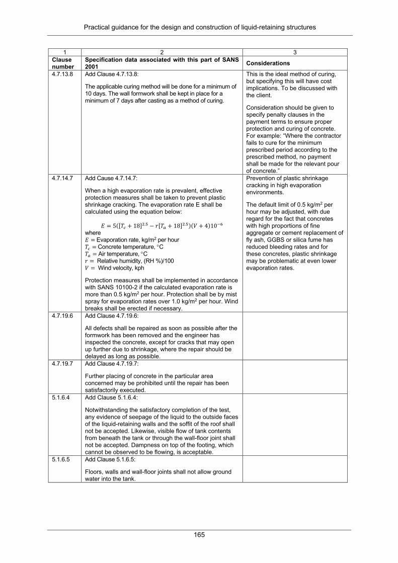
Practical guidance for the design and construction of liquid-retaining structures
165
1 2 3 Clause number
Specification data associated with this part of SANS 2001 Considerations
4.7.13.8 Add Clause 4.7.13.8: The applicable curing method will be done for a minimum of 10 days. The wall formwork shall be kept in place for a minimum of 7 days after casting as a method of curing.
This is the ideal method of curing, but specifying this will have cost implications. To be discussed with the client. Consideration should be given to specify penalty clauses in the payment terms to ensure proper protection and curing of concrete. For example: “Where the contractor fails to cure for the minimum prescribed period according to the prescribed method, no payment shall be made for the relevant pour of concrete.”
4.7.14.7 Add Cause 4.7.14.7: When a high evaporation rate is prevalent, effective protection measures shall be taken to prevent plastic shrinkage cracking. The evaporation rate E shall be calculated using the equation below:
𝐸𝐸 = 5([𝑇𝑇𝑃𝑃 + 18]2.5 − 𝑟𝑟[𝑇𝑇𝑎𝑎 + 18]2.5)(𝑉𝑉 + 4)10−6 where 𝐸𝐸 = Evaporation rate, kg/m2 per hour 𝑇𝑇𝑃𝑃 = Concrete temperature, °C 𝑇𝑇𝑎𝑎 = Air temperature, °C 𝑟𝑟 = Relative humidity, (RH %)/100 𝑉𝑉 = Wind velocity, kph Protection measures shall be implemented in accordance with SANS 10100-2 if the calculated evaporation rate is more than 0.5 kg/m2 per hour. Protection shall be by mist spray for evaporation rates over 1.0 kg/m2 per hour. Wind breaks shall be erected if necessary.
Prevention of plastic shrinkage cracking in high evaporation environments. The default limit of 0.5 kg/m2 per hour may be adjusted, with due regard for the fact that concretes with high proportions of fine aggregate or cement replacement of fly ash, GGBS or silica fume has reduced bleeding rates and for these concretes, plastic shrinkage may be problematic at even lower evaporation rates.
4.7.19.6 Add Clause 4.7.19.6: All defects shall be repaired as soon as possible after the formwork has been removed and the engineer has inspected the concrete, except for cracks that may open up further due to shrinkage, where the repair should be delayed as long as possible.
4.7.19.7 Add Clause 4.7.19.7: Further placing of concrete in the particular area concerned may be prohibited until the repair has been satisfactorily executed.
5.1.6.4 Add Clause 5.1.6.4: Notwithstanding the satisfactory completion of the test, any evidence of seepage of the liquid to the outside faces of the liquid-retaining walls and the soffit of the roof shall not be accepted. Likewise, visible flow of tank contents from beneath the tank or through the wall-floor joint shall not be accepted. Dampness on top of the footing, which cannot be observed to be flowing, is acceptable.
5.1.6.5 Add Clause 5.1.6.5: Floors, walls and wall-floor joints shall not allow ground water into the tank.

Practical guidance for the design and construction of liquid-retaining structures
166
1 2 3 Clause number
Specification data associated with this part of SANS 2001 Considerations
5.1.6.6 Add Clause 5,1.6.6: If required by the engineer, the structure shall be retested before the expiry of the defects liability period. The works will not be certified complete until the structure has been proved by testing to be watertight and seepage free according to clauses 5.1.6.1 to 5.1.6.5.
5.1.6.7 Add Clause 5.1.6.7: Testing shall only take place after all ferrule holes and pipe penetrations have been grouted, all sluices have been installed, all joints have been sealed and the structure has been cleaned and disinfected (if applicable, see Clause 5.1.6.9).
5.1.6.8 Add Clause 5.1.6.8: The roof insulation covering should be completed as soon as possible after satisfactory testing of the roof.
5.1.6.9 Add Clause 5.1.6.8: On completion of the structure, the entire inside surface of the reservoir, including columns and roof, and all surfaces that will be in contact with stored potable water, shall be thoroughly hosed down with water and properly cleaned of all dirt and other foreign matter by high-pressure water jet, sweeping or scrubbing. All water, dirt, foreign material and work items must be discharged or removed. After cleaning, the overflow and vents shall be screened to avoid birds, insects or contaminants from entering the structure.

Practical guidance for the design and construction of liquid-retaining structures
167
1 2 3 Clause number
Specification data associated with this part of SANS 2001 Considerations
5.1.6.10 Add Clause 5.1.6.9: The inside and pipes of clear/potable water retaining structures shall be disinfected before testing of the walls. Disinfection is achieved by chlorination. Any one of the three common methods specifiied in C652: Disinfection of water storage facilities (American Water Works Association), and summarised below may be used. Adequate safety measures shall be implemented to safeguard personnel and the public. Method 1: Fill the water storage tank to the overflow level with potable water to which enough chlorine is added to provide a free chlorine residual of at least 10 mg/ℓ after 24 hours. Even mixing of chlorine with the water entering the tank shall be ensured. After the retention period, the chlorine concentration shall be reduced to 2 mg/ℓ by a combination of additional holding time and blending with potable water. Subject to satisfactory bacteriological testing, such water may then be distributed. Discharging chlorinated water causes environmental damage and shall not be done without written permission from the local authority. A reducing agent shall be applied to water to be wasted to neutralise the chlorine residual prior to discharge. Method 2: All surfaces that will be in contact with stored potable water shall be painted or sprayed with a solution of 200 mg/ℓ available chlorine, in such a way that the surface remains wet for at least 30 minutes. Piping shall be disinfected with water of available chlorine not less than 10 mg/ℓ, to be drained after 30 minutes. The tank may then be filled with potable water to its overflow level. Subject to satisfactory bacteriological testing, such water may be distributed. Method 3: Some 5% of the storage volume shall be filled with water of 50 mg/ℓ available chlorine and held for at least 6 hours. The tank shall then be filled to overflow by adding potable water and held for at least 24 hours, maintaining at least 2 mg/ℓ available chlorine. Subject to satisfactory bacteriological testing, the water may then be distributed. All remaining highly chlorinated water shall be drained from piping prior to distribution.
5.1.6.11 Add Clause 5.1.6.10 Chlorinated water shall be stored until the free chlorine level has dropped to an acceptable level. Chlorinated water and excess dirt swept from the floor into the sump may be discharged subject to written approval being obtained from the local authority.
APPENDIX B: SANS 1200 G VS SANS 2100 CC1: CURSORY COMPARISON OF TECHNICAL CONTENT
SANS 1200 G (1982)
SANS 2001 CC1 (2012) Comment
Scope Clause 1 Clause 2.1
Clause 1 Clause 2
Amended (pre-stressed and precast concrete added ) Amended (new references added )
Interpretations
Clause 2.3(a).1 Clause 2.3(a).2 clause 2.3(a).3
Clause 3.2.1 Clause 3.1.1 Clause 3.2.2
Verbatim Amended Verbatim
Practical guidance for the design and construction of liquid-retaining structures
168
Clause 2.3(a).4 Clause 2.3(a).5 Clause 2.3(a).6 Clause 2.3(a).7 Clause 2.3(a).8 Clause 2.3(a).9 Clause 2.3(b).1 Clause 2.3(b).2 Clause 2.3(b).3 Clause 2.3(b).4 Clause 2.3(b).5 Clause 2.3(b).6 Clause 2.3(b).7 Clause 2.3(b).8 Clause 2.3(c).1 Clause 2.3(c).2 Clause 2.3(c).3 '-------------
Clause 3.1.4 Clause 3.2.3 Clause 3.1.8 Clause 3.1.9 Clause 3.2.4 Clause 3.2.5 Clause 3.3.2 Clause 3.3.3 Clause 3.3.7 Clause 3.3.9 Clause 3.3.10 clause 3.4.3 Clause 3.3.11 Clause 3.3.12 Clause 3.4.2 Clause 3.4.3 Clause 3.4.4 Clause 3.1.2 ,3.1.3, 3.1.5-13, 3.3.4-6, 3.4.1, 3.5
Amended (pre-stressing steel added) Verbatim Verbatim Verbatim Verbatim Verbatim Verbatim Verbatim Verbatim Amended (Specifications: SANS 2001 and SANS 878) Verbatim Amended (further description) Amended Verbatim Amended (improved description of "target slump") Amended (improved description of "target strength for concrete") Amended (improved description of "valid test results" in accordance with SANS 5860, SANS 5861-2 and SANS 5863) New provisions (definitions for: admixture, cementitious binder, deviation, extender, falsework, fixture, formwork, permissible deviation, specification data, tolerance, no-fines concrete, plain concrete, precast concrete, characteristics strength, pre-stressing)
Clause 2.4.1 Clause 2.4.2 Clause 2.4.3
----------- ----------- -----------
Provisions deleted (explanation of terms/exposure conditions) Provisions deleted Provisions deleted
Materials -------------- Clause 3.1 Clause 3.2.1/2 Clause 3.2.3 -------------- Clause 3.3 Clause 3.4 Clause 3.5 Clause 3.6 Clause 3.8 Clause 3.7 -------------- Clause 4.1-4 Clause 4.5
Clause 4.1 ------------ Clause 4.2.1.1 Clause 4.2.1.2 Clause 4.2.1.3 Clause 4.2.2 Clause 4.2.3 Clause 4.2.4 Clause 4.2.5 Clause 4.2.12 Clause 4.2.13 Clause 4.2.6-11 ------------ Clause 4.3.2
New provision (General: subsections 4.1.1/2 added) Provision deleted (approval of materials) Amended (new specifications of cement added) Verbatim New provision Amended (Specification SANS 51008 added) Amended and new provisions added Amended (engineers approval removed and new provisions added) Verbatim Verbatim Verbatim New provision Provisions deleted (batching plants, mixing plant, vibrators) Amended (new provisions, falsework and sliding formwork)
Construction
Clause 5.1.1 Clause 5.1.2 Clause 5.1.3 Clause 5.1.4/5 -------------- -------------- Clause 5.2.2 Clause 5.2.3 Clause 5.2.4 Clause 5.2.5 Clause 5.3 Clause 5.4 -------------- Clause 5.5.1.1 Clause 5.5.1.2 Clause 5.5.1.3 Clause 5.5.1.4 Clause 5.5.1.5
Clause 4.4.1 Clause 4.4.2.1 Clause 4.4.3 Clause 4.4.2.5 Clause 4.4.2.3-4, Clause 4.4.2.6/7 Clause 4.3.3, Clause 4.3.5 Clause 4.3.6 Clause 4.3.7 Clause 4.3.4 Clause 4.3.8 Clause 4.5 Clause 4.6.3 Clauses 4.6.1, 4.6.2, 4.6.4 Clause 4.7.1 Clause 4.7.2 Clause 4.7.3 Clause 4.7.4 Clause 4.7.5
Amended (new provisions added) Amended (description, engineers approval removed) Amended (table of minimum cover amended), Verbatim (Subsection 4.4.3.1/2), new provisions (clauses 4.4.3.3) Amended (further description ) New provisions New provisions Amended (new provisions Clause 4.3.6.1, Clause 4.3.6.3) Verbatim Verbatim Amended (new provisions Clause 4.3.8.2-5), Table 2 amended Amended and clauses 4.5.2/3 new provisions Amended and new provisions (clauses 4.6.3.2/3) New provisions Amended (description) and new provisions (Clause 4.7.1.2) Amended and new provisions (Clause 4.7.2.2) Amended/Clause 4.7.3.2 new provisions Amended/Clause 4.7.4.2 new provisions Amended/Clause 4.7.5.1/2 new provision, Table 5 of 1200 deleted, Table 6 new provision

Practical guidance for the design and construction of liquid-retaining structures
169
Clause 5.5.1.6 Clause 5.5.1.7
Clause 4.7.6 ---------
Amended (description) Provision deleted (strength of concrete)
Batching
Clause 5.5.2 Clause 5.5.3.1 Clause 5.5.3.2 ------------ ------------ Clause 5.5.4 ------------- Clause 5.5.5.1-9 ------------- Clause 5.5.6.1-4 ------------- Clause 5.5.7.1-3 ------------- ------------- Clause 5.5.8 Clause 5.5.9 Clause 5.5.10 Clause 5.5.11-12 Clause 5.5.13 Clause 5.5.14 Clause 5.5.15
Clause 4.7.7 Clause 4.7.8.1 Clause 4.7.8.2 Clause 4.7.8.3 Clause 4.7.8.4 Clause 4.7.9.1 Clause 4.7.9.2-3 Clauses 4.7.10.1-5, 4.7.10.7-8, 4.7.10.13-15 Clauses 4.7.10.6, 4.7.10.9-12, 4.7.10.16-17 Clause 4.7.11.1-3, 4.7.11.7 Clause 4.7.11.4-6, 4.7.11.8 Clause 4.7.12.1.1-3 Clause 4.7.12.1.4 Clause 4.7.12.2-4 Clause 4.7.13 Clause 4.7.14 Clause 4.7.15 Clause 4.7.16-17 Clause 4.7.18 Clause 4.7.19 Clause 4.7.22
Verbatim Amended and Clause 4.7.8.1.2 new provision Amended (specification, description) New provision New provision Verbatim New provision Verbatim New provisions Verbatim New provisions Verbatim New provision New provision Verbatim (Subsection 4.7.13.2, 4.7.13.4), new provision (Subsection 4.7.13.1/2, 4.7.13.3, 4.7.13.5-7) Verbatim (subsections 4.7.14.1/2, 4.7.14.6) and new provision (subsections 4.7.14.3-5) Amended (Subsection 4.7.15.1), Verbatim (Subsection 4.7.15.3), new provision (Subsection 4.7.15.2, 4.7.15.4) Verbatim Verbatim (subsections 4.7.18.1-3), new provision (subsections 4.7.18.4/5) Verbatim (Subsection 4.7.19.1), new provision (Subsection 4.7.19.2-5), Not included in SANS 2001(Clause 5.5.14.2) Verbatim
-------------- -------------- -------------- --------------
Clause 4.7.20/21, 4.7.23 Clause 4.9 Clause 4.8 Clause 4.10
New provisions (rubbing down of concrete surfaces, the use of sliding formwork, demolition and removal of existing structural concrete New provision (precast concrete) New provision (pre-stressed concrete) New provision (handling and erection of precast concrete units)
Tolerance
Clause 6.1.1/2 Clause 6.2.1 Clause 6.2.2 Clause 6.2.3 -------------- Clause 7.1.1 Clause 7.1.2 --------------
Clause 5.2.1 --------- Clause 5.2.4 Table 11 & 12 Clause 5.2.2-8 ---------------- Clause 5.1.3 Clause 5.1.4-6
Verbatim (Subsection 5.2.1.1-5), new provisions (Subsection 5.2.1.6) Provision deleted (General) Verbatim Verbatim New provision Provision deleted (facilities) Verbatim New provision (individual load tests on precast units and pre-stressed units, tests on pre-stressed structures, yests for water tightness, test for sulfate content)
Tests
Clause 7.2 Clause 7.2.4 Clause 7.3 Clause 7.3.5
Clause 5.1.1 Annex B (h) Clause 5.1.2 ------------
Verbatim (Subsection 5.1.1.5), new provision (Subsection 5.1.1.1-4, 5.1.1.6-8), provisions deleted (Subsection 7.2.1) Verbatim Verbatim (Subsection 5.1.2.1, 5.1.2.3/4), amended (Subsection 5.1.2.2 by including Table 9), new provision (Subsection 5.1.2.5) Provision deleted (replacement and strengthening of concrete)
Measurement and Payment
Clause 8 ------------ Provisions deleted

Practical guidance for the design and construction of liquid-retaining structures
170