PowerCube 1000 V300R002C01 Solution Description - huawei… · PowerCube 1000 V300R002C01...
71
PowerCube 1000 V300R002C01 Solution Description Issue 02 Date 2013-05-08 HUAWEI TECHNOLOGIES CO., LTD.
Transcript of PowerCube 1000 V300R002C01 Solution Description - huawei… · PowerCube 1000 V300R002C01...
PowerCube 1000 V300R002C01
Solution Description
Issue 02
Date 2013-05-08
HUAWEI TECHNOLOGIES CO., LTD.

Issue 02 (2013-05-08) Huawei Proprietary and Confidential
Copyright © Huawei Technologies Co., Ltd.
i
Copyright © Huawei Technologies Co., Ltd. 2013. All rights reserved.
No part of this document may be reproduced or transmitted in any form or by any means without
prior written consent of Huawei Technologies Co., Ltd.
Trademarks and Permissions
and other Huawei trademarks are trademarks of Huawei Technologies Co., Ltd.
All other trademarks and trade names mentioned in this document are the property of their respective
holders.
Notice
The purchased products, services and features are stipulated by the contract made between Huawei and
the customer. All or part of the products, services and features described in this document may not
be within the purchase scope or the usage scope. Unless otherwise specified in the contract, all
statements, information, and recommendations in this document are provided "AS IS" without warranties,
guarantees or representations of any kind, either express or implied.
The information in this document is subject to change without notice. Every effort has been made in the
preparation of this document to ensure accuracy of the contents, but all statements, information, and
recommendations in this document do not constitute a warranty of any kind, express or implied.
Huawei Technologies Co., Ltd.
Address: Huawei Industrial Base
Bantian, Longgang
Shenzhen 518129
People's Republic of China
Website: http://www.huawei.com
Email: [email protected]
PowerCube 1000
Solution Description About This Document
Issue 02 (2013-05-08) Huawei Proprietary and Confidential
Copyright © Huawei Technologies Co., Ltd.
ii
About This Document
Purpose
PowerCube 1000 V300R002C01 (PowerCube 1000 for short) is a hybrid power supply
solution that uses solar energy, fuel, and mains as the main sources. This document describes
the PowerCube 1000 in terms of its positioning, benefits, functions, features, and architecture,
and details its three sub-solutions in terms of their application scenarios, system
configurations, network diagrams, model description, working modes, and components.
Intended Audience
This document is intended for:
Policy planning engineers
Installation and commissioning engineers
NM configuration engineers
Technical support engineers
Symbol Conventions
The symbols that may be found in this document are defined as follows.
Symbol Description
Alerts you to a high risk hazard that could, if not avoided,
result in serious injury or death.
Alerts you to a medium or low risk hazard that could, if not
avoided, result in moderate or minor injury.
Alerts you to a potentially hazardous situation that could, if not
avoided, result in equipment damage, data loss, performance
deterioration, or unanticipated results.
Provides a tip that may help you solve a problem or save time.
Provides additional information to emphasize or supplement
important points in the main text.
PowerCube 1000
Solution Description About This Document
Issue 02 (2013-05-08) Huawei Proprietary and Confidential
Copyright © Huawei Technologies Co., Ltd.
iii
Change History
Changes between document issues are cumulative. The latest document issue contains all the
changes made in earlier issues.
Issue 02 (2013-05-08)
Low wrong revision.
Issue 01 (2012-10-26)
This issue is used for first office application (FOA).
PowerCube 1000
Solution Description Contents
Issue 02 (2013-05-08) Huawei Proprietary and Confidential
Copyright © Huawei Technologies Co., Ltd.
iv
Contents
About This Document .................................................................................................................... ii
1 Overview ......................................................................................................................................... 1
1.1 Context ............................................................................................................................................................. 1
1.2 Positioning ....................................................................................................................................................... 1
1.3 Benefits ............................................................................................................................................................ 1
2 Functions and Features ................................................................................................................ 4
3 Architecture .................................................................................................................................... 6
3.1 Introduction ...................................................................................................................................................... 6
3.2 EPS ................................................................................................................................................................... 7
3.3 ICC ................................................................................................................................................................... 7
3.4 ESS ................................................................................................................................................................... 8
3.5 Cabinet System ................................................................................................................................................. 8
3.6 Network Monitoring and Management System................................................................................................ 9
4 Indoor Hybrid Power System ................................................................................................... 10
4.1 Application Scenarios and Configurations ..................................................................................................... 10
4.1.1 Application Scenarios ........................................................................................................................... 10
4.1.2 System Configuration ........................................................................................................................... 10
4.1.3 Network Diagrams ................................................................................................................................ 13
4.2 Model Description .......................................................................................................................................... 18
4.3 Working Modes .............................................................................................................................................. 19
4.4 Open Rack and Cabine ................................................................................................................................... 19
4.4.1 Open Rack ............................................................................................................................................. 19
4.4.2 Outdoor Battery Cabinet ....................................................................................................................... 20
4.4.3 Indoor Battery Rack .............................................................................................................................. 21
4.5 EPS Components ............................................................................................................................................ 22
4.5.1 D.G. ....................................................................................................................................................... 22
4.5.2 PV Module ............................................................................................................................................ 22
4.5.3 PV Module Support .............................................................................................................................. 23
4.5.4 SJB ........................................................................................................................................................ 24
4.6 ICC Components ............................................................................................................................................ 25
4.6.1 ECC500 ................................................................................................................................................. 25

PowerCube 1000
Solution Description Contents
Issue 02 (2013-05-08) Huawei Proprietary and Confidential
Copyright © Huawei Technologies Co., Ltd.
v
4.6.2 SAU-03A .............................................................................................................................................. 26
4.6.3 ATS-63A1 ............................................................................................................................................. 27
4.6.4 ACDU-63A1 ......................................................................................................................................... 27
4.6.5 DCDU-400A1 ....................................................................................................................................... 28
4.6.6 PVDU-60A1 ......................................................................................................................................... 29
4.6.7 S4850G1 ............................................................................................................................................... 30
4.6.8 PSU ....................................................................................................................................................... 31
4.6.9 BC1203&BC1203D .............................................................................................................................. 31
4.6.10 ETP24160A3....................................................................................................................................... 32
4.6.11 Inverter ................................................................................................................................................ 33
4.7 ESS Components ............................................................................................................................................ 34
4.7.1 DCB-A .................................................................................................................................................. 34
4.7.2 SCB ....................................................................................................................................................... 35
5 Outdoor Hybrid Power System ................................................................................................ 37
5.1 Application Scenarios and Configurations ..................................................................................................... 37
5.1.1 Application Scenarios ........................................................................................................................... 37
5.1.2 System Configuration ........................................................................................................................... 37
5.1.3 Network Diagrams ................................................................................................................................ 41
5.2 Model Description .......................................................................................................................................... 41
5.3 Working Modes .............................................................................................................................................. 41
5.4 Cabinets .......................................................................................................................................................... 42
5.4.1 ICC700-A .............................................................................................................................................. 42
5.4.2 ICC900-D .............................................................................................................................................. 43
5.4.3 ICC310-H1 ............................................................................................................................................ 43
5.4.4 Outdoor Battery Cabinet ....................................................................................................................... 45
5.5 ICC Components ............................................................................................................................................ 45
5.6 ESS Components ............................................................................................................................................ 45
6 Co-site Hybrid Power System ................................................................................................... 46
6.1 Application Scenarios and Configurations ..................................................................................................... 46
6.1.1 Application Scenarios ........................................................................................................................... 46
6.1.2 System Configuration ........................................................................................................................... 46
6.1.3 Network Diagrams ................................................................................................................................ 47
6.2 Model Description .......................................................................................................................................... 47
6.3 Working Modes .............................................................................................................................................. 48
6.4 Cabinet ........................................................................................................................................................... 48
6.4.1 ICC900-HA2 ......................................................................................................................................... 48
6.5 Main Components .......................................................................................................................................... 49
6.5.1 IDU ....................................................................................................................................................... 49
6.5.2 PSU ....................................................................................................................................................... 51
6.5.3 S4850G1 ............................................................................................................................................... 51
7 Indoor Sites with Upgraded TCUs .......................................................................................... 52
PowerCube 1000
Solution Description Contents
Issue 02 (2013-05-08) Huawei Proprietary and Confidential
Copyright © Huawei Technologies Co., Ltd.
vi
7.1 Split-Type DC Variable Frequency Air Conditioner (Optional) ..................................................................... 52
7.1.1 System Configuration ........................................................................................................................... 52
7.1.2 Network Diagrams ................................................................................................................................ 52
7.1.3 Model Description ................................................................................................................................ 54
7.1.4 Appearance ............................................................................................................................................ 54
7.1.5 Technical Specifications ........................................................................................................................ 55
7.2 EcoCool Configuration (Optional) ................................................................................................................. 56
8 Monitoring.................................................................................................................................... 57
8.1 New Monitoring Functions ............................................................................................................................ 57
8.2 GMU-01A ...................................................................................................................................................... 57
9 NetEco Management ................................................................................................................... 59
A Glossary ....................................................................................................................................... 61
B Acronyms and Abbreviations .................................................................................................. 62
PowerCube 1000
Solution Description 1 Overview
Issue 02 (2013-05-08) Huawei Proprietary and Confidential
Copyright © Huawei Technologies Co., Ltd.
1
1 Overview
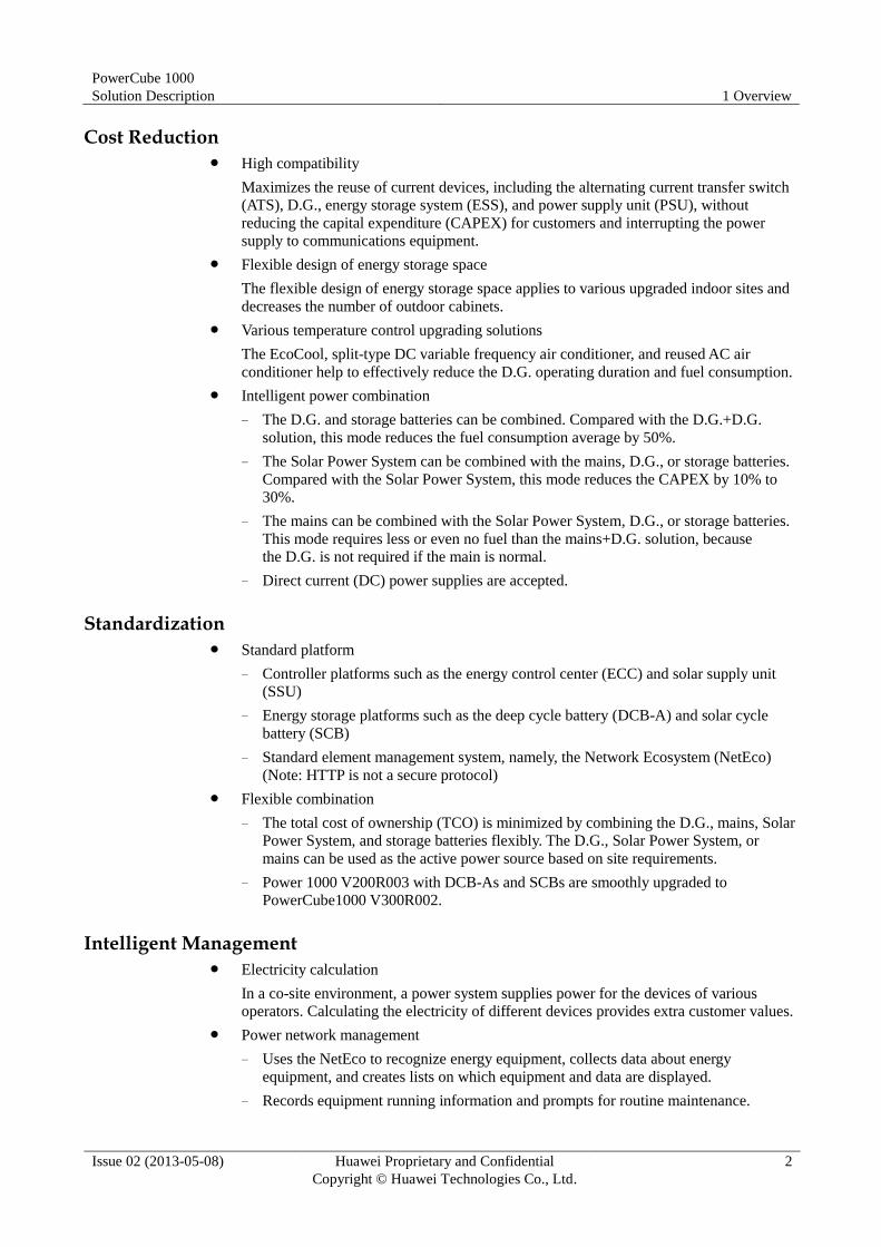
1.1 Context
In an upgraded indoor or shared site with traditional diesel generators, customers face many
problems such as great fuel consumption caused by long D.G. operating duration,
frequent D.G. maintenance, fuel thefts, no remote energy management and monitoring, and
difficulty in capacity expansion.
To provide competitive site energy solutions, Huawei launches PowerCube series hybrid
power supply solutions, including the PowerCube-Diesel Hybrid, PowerCube-Solar Hybrid,
and PowerCube-Grid Hybrid.
In addition, Huawei evolves PowerCube 1000 V300R002C00 into PowerCube 1000
V300R002C01.
1.2 Positioning
The PowerCube 1000 is used in the areas with mains absence, low mains quality, and mains
unsteadiness, and contains the following systems:
Indoor hybrid power system
Outdoor hybrid power system
Co-site hybrid power system
Indoor temperature control unit (TCU)
Mains absence: The outage duration is 24 hours per day.
Mains unsteadiness: The outage duration is less than 12 hours per day.
Low mains quality: The outage duration is greater than 12 hours per day.
1.3 Benefits
The PowerCube 1000 has the following benefits:
NOTE
PowerCube 1000
Solution Description 1 Overview
Issue 02 (2013-05-08) Huawei Proprietary and Confidential
Copyright © Huawei Technologies Co., Ltd.
2
Cost Reduction High compatibility
Maximizes the reuse of current devices, including the alternating current transfer switch
(ATS), D.G., energy storage system (ESS), and power supply unit (PSU), without
reducing the capital expenditure (CAPEX) for customers and interrupting the power
supply to communications equipment.
Flexible design of energy storage space
The flexible design of energy storage space applies to various upgraded indoor sites and
decreases the number of outdoor cabinets.
Various temperature control upgrading solutions
The EcoCool, split-type DC variable frequency air conditioner, and reused AC air
conditioner help to effectively reduce the D.G. operating duration and fuel consumption.
Intelligent power combination
− The D.G. and storage batteries can be combined. Compared with the D.G.+D.G.
solution, this mode reduces the fuel consumption average by 50%.
− The Solar Power System can be combined with the mains, D.G., or storage batteries.
Compared with the Solar Power System, this mode reduces the CAPEX by 10% to
30%.
− The mains can be combined with the Solar Power System, D.G., or storage batteries.
This mode requires less or even no fuel than the mains+D.G. solution, because
the D.G. is not required if the main is normal.
− Direct current (DC) power supplies are accepted.
Standardization Standard platform
− Controller platforms such as the energy control center (ECC) and solar supply unit
(SSU)
− Energy storage platforms such as the deep cycle battery (DCB-A) and solar cycle
battery (SCB)
− Standard element management system, namely, the Network Ecosystem (NetEco)
(Note: HTTP is not a secure protocol)
Flexible combination
− The total cost of ownership (TCO) is minimized by combining the D.G., mains, Solar
Power System, and storage batteries flexibly. The D.G., Solar Power System, or
mains can be used as the active power source based on site requirements.
− Power 1000 V200R003 with DCB-As and SCBs are smoothly upgraded to
PowerCube1000 V300R002.
Intelligent Management Electricity calculation
In a co-site environment, a power system supplies power for the devices of various
operators. Calculating the electricity of different devices provides extra customer values.
Power network management
− Uses the NetEco to recognize energy equipment, collects data about energy
equipment, and creates lists on which equipment and data are displayed.
− Records equipment running information and prompts for routine maintenance.

PowerCube 1000
Solution Description 1 Overview
Issue 02 (2013-05-08) Huawei Proprietary and Confidential
Copyright © Huawei Technologies Co., Ltd.
3
− Ensures electrical safety and security by using a theft prevention design and alarm
generation function for fuel and solar energy.

PowerCube 1000
Solution Description 2 Functions and Features
Issue 02 (2013-05-08) Huawei Proprietary and Confidential
Copyright © Huawei Technologies Co., Ltd.
4
2 Functions and Features
Table 2-1 describes the PowerCube 1000 functions and features.
Table 2-1 PowerCube 1000 functions and features
Item Benefit Application Scenario Working Mode
Indoor hybrid
power system
Reuses customer
equipment,
reducing the
CAPEX.
Provides
continuous
power supply to
communications
equipment
during
upgrading.
The space for the hybrid
power system is provided
indoors.
Solar power system
Solar-D.G. hybrid
power system
Solar-D.G.- mains
hybrid power system
D.G.-mains-battery
hybrid power system
(reused power
system; reused
Energy Plant
System)
Outdoor
hybrid power
system
The space for the hybrid
power system is provided
outdoors.
Co-site
hybrid power
system
Supplies power
for the devices
from a maximum
of four operators.
The space for the hybrid
power system is provided
outdoors.
Solar-D.G. hybrid
power system
Solar-D.G.- mains
hybrid power system
D.G.-mains-battery
hybrid power system
Indoor
temperature
control unit
(TCU)
The
split-type DC
variable
frequency air
conditioner is
easy to install
and provides
limited damage
to walls.
48 V DC input One split-type DC
variable frequency
air conditioner
Two split-type DC
variable frequency
air
conditioners workin
g alternately
PowerCube 1000
Solution Description 2 Functions and Features
Issue 02 (2013-05-08) Huawei Proprietary and Confidential
Copyright © Huawei Technologies Co., Ltd.
5
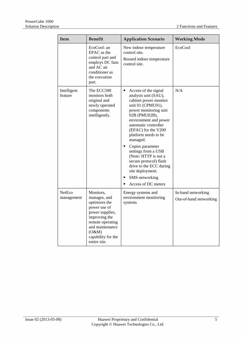
Item Benefit Application Scenario Working Mode
EcoCool: an
EPAC as the
control part and
employs DC fans
and AC air
conditioner as
the execution
part.
New indoor temperature
control site.
Reused indoor temperature
control site.
EcoCool
Intelligent
feature
The ECC500
monitors both
original and
newly operated
components
intelligently.
Access of the signal
analysis unit (SAU),
cabinet power monitor
unit 01 (CPMU01),
power monitoring unit
02B (PMU02B),
environment and power
automatic controller
(EPAC) for the V200
platform needs to be
managed.
Copies parameter
settings from a USB
(Note: HTTP is not a
secure protocol) flash
drive to the ECC during
site deployment.
SMS networking
Access of DC meters
N/A
NetEco
management
Monitors,
manages, and
optimizes the
power use of
power supplies,
improving the
remote operating
and maintenance
(O&M)
capability for the
entire site.
Energy systems and
environment monitoring
systems
In-band networking
Out-of-band networking

PowerCube 1000
Solution Description 3 Architecture
Issue 02 (2013-05-08) Huawei Proprietary and Confidential
Copyright © Huawei Technologies Co., Ltd.
6
3 Architecture
3.1 Introduction
The PowerCube consists of the following systems by function: Integrated Controller and
Converter (ICC), energy storage system (ESS), energy plant system (EPS), cabinet system,
and network monitoring and management system. Figure 3-1 shows the network diagram of
the systems.
Figure 3-1 Network diagram
PowerCube 1000
Solution Description 3 Architecture
Issue 02 (2013-05-08) Huawei Proprietary and Confidential
Copyright © Huawei Technologies Co., Ltd.
7
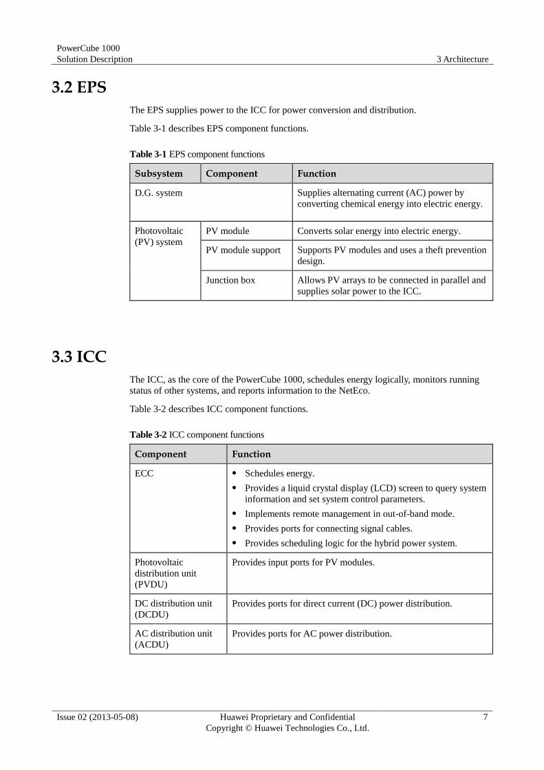
3.2 EPS
The EPS supplies power to the ICC for power conversion and distribution.
Table 3-1 describes EPS component functions.
Table 3-1 EPS component functions
Subsystem Component Function
D.G. system Supplies alternating current (AC) power by
converting chemical energy into electric energy.
Photovoltaic
(PV) system
PV module Converts solar energy into electric energy.
PV module support Supports PV modules and uses a theft prevention
design.
Junction box Allows PV arrays to be connected in parallel and
supplies solar power to the ICC.
3.3 ICC
The ICC, as the core of the PowerCube 1000, schedules energy logically, monitors running
status of other systems, and reports information to the NetEco.
Table 3-2 describes ICC component functions.
Table 3-2 ICC component functions
Component Function
ECC Schedules energy.
Provides a liquid crystal display (LCD) screen to query system
information and set system control parameters.
Implements remote management in out-of-band mode.
Provides ports for connecting signal cables.
Provides scheduling logic for the hybrid power system.
Photovoltaic
distribution unit
(PVDU)
Provides input ports for PV modules.
DC distribution unit
(DCDU)
Provides ports for direct current (DC) power distribution.
AC distribution unit
(ACDU)
Provides ports for AC power distribution.
PowerCube 1000
Solution Description 3 Architecture
Issue 02 (2013-05-08) Huawei Proprietary and Confidential
Copyright © Huawei Technologies Co., Ltd.
8
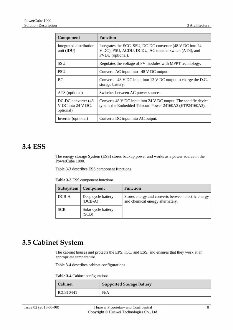
Component Function
Integrated distribution
unit (IDU)
Integrates the ECC, SSU, DC-DC converter (48 V DC into 24
V DC), PSU, ACDU, DCDU, AC transfer switch (ATS), and
PVDU (optional).
SSU Regulates the voltage of PV modules with MPPT technology.
PSU Converts AC input into –48 V DC output.
BC Converts –48 V DC input into 12 V DC output to charge the D.G.
storage battery.
ATS (optional) Switches between AC power sources.
DC-DC converter (48
V DC into 24 V DC,
optional)
Converts 48 V DC input into 24 V DC output. The specific device
type is the Embedded Telecom Power 24160A3 (ETP24160A3).
Inverter (optional) Converts DC input into AC output.
3.4 ESS
The energy storage System (ESS) stores backup power and works as a power source in the
PowerCube 1000.
Table 3-3 describes ESS component functions.
Table 3-3 ESS component functions
Subsystem Component Function
DCB-A Deep cycle battery
(DCB-A)
Stores energy and converts between electric energy
and chemical energy alternately.
SCB Solar cycle battery
(SCB)
3.5 Cabinet System
The cabinet houses and protects the EPS, ICC, and ESS, and ensures that they work at an
appropriate temperature.
Table 3-4 describes cabinet configurations.
Table 3-4 Cabinet configurations
Cabinet Supported Storage Battery
ICC310-H1 N/A
PowerCube 1000
Solution Description 3 Architecture
Issue 02 (2013-05-08) Huawei Proprietary and Confidential
Copyright © Huawei Technologies Co., Ltd.
9
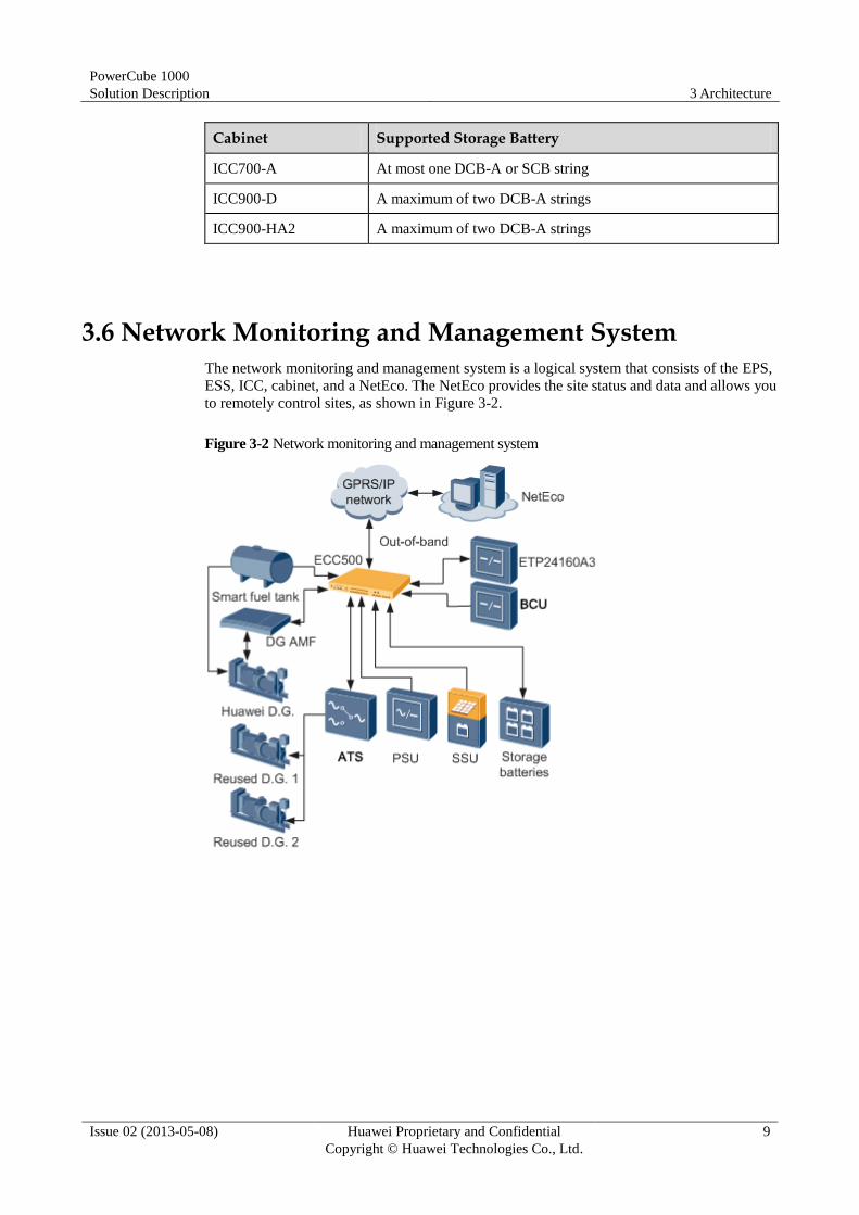
Cabinet Supported Storage Battery
ICC700-A At most one DCB-A or SCB string
ICC900-D A maximum of two DCB-A strings
ICC900-HA2 A maximum of two DCB-A strings
3.6 Network Monitoring and Management System
The network monitoring and management system is a logical system that consists of the EPS,
ESS, ICC, cabinet, and a NetEco. The NetEco provides the site status and data and allows you
to remotely control sites, as shown in Figure 3-2.
Figure 3-2 Network monitoring and management system

PowerCube 1000
Solution Description 4 Indoor Hybrid Power System
Issue 02 (2013-05-08) Huawei Proprietary and Confidential
Copyright © Huawei Technologies Co., Ltd.
10
4 Indoor Hybrid Power System
4.1 Application Scenarios and Configurations
4.1.1 Application Scenarios
The power system for upgraded outdoor sites applies to the following scenarios:
− Solar power system
− Solar-D.G. hybrid power system
− Solar-D.G.- mains hybrid power system
− D.G.-mains-battery hybrid power system
Solar-D.G. hybrid power system and Solar-D.G.- mains hybrid power system are reused
EPS.
In D.G.-mains-battery hybrid power system, both power system and EPS can be reused.
D.G.-mains-battery hybrid power system contains three working modes
− D.G.+ battery alternate working mode
− D.G.+D.G.+ battery alternate working mode
− Mains+D.G.+ battery alternate working mode
4.1.2 System Configuration
Table 4-1 describes the indoor hybrid power system configuration.
Table 4-1 Configuration description for the Indoor Hybrid Power System
Product Series
Scenario Integrated Controller and Converter
ESS ICC Cabinet
ESS Cabinet
Scenario NO.
Solar
Hybrid(
S)
Solar power
system with an
indoor ICC
DCDU-400
A1
One to
Two
SCB
strings
Indoor
open rack
Outdoor
battery
cabinet
1
SSU
PVDU

PowerCube 1000
Solution Description 4 Indoor Hybrid Power System
Issue 02 (2013-05-08) Huawei Proprietary and Confidential
Copyright © Huawei Technologies Co., Ltd.
11
Product Series
Scenario Integrated Controller and Converter
ESS ICC Cabinet
ESS Cabinet
Scenario NO.
Solar-D.G. power
system with an
indoor ICC
ACDU-63
A1
(optional)
One to
Two D
CB-A
or SCB
strings
Indoor
open rack
Indoor
battery
rack or
outdoor
battery
cabinet
2
DCDU-400
A1
PSU
SSU
PVDU
BC1203(op
tional)
Solar-D.G.-mains
power system with
an indoor ICC
ATS-63A1 One to
Two D
CB-A
or SCB
strings
Indoor
open rack
Indoor
battery
rack or
outdoor
battery
cabinet
3
DCDU-400
A1
PSU
SSU
PVDU
BC1203(op
tional)
Diesel
Hybrid(
D)
D.G.-main
s-battery
power
system wit
h an
indoor
ICC
Reuse
d
EPS
ATS-63A1
(optional)
One to
two DC
B-A
strings
Indoor
open rack
Indoor
battery
rack or
outdoor
battery
cabinet
4
ACDU-63
A1(optiona
l)
DCDU-400
A1
PSU
BC1203 or
BC1203D
(optional)
Reuse
d
powe
r
syste
m
ECC500 One to
two DC
B-A
strings
Indoor
open rack
(optional
)
Indoor
battery
rack or
outdoor
battery
cabinet
5
SAU-03A
BC1203
Note: ETP24160A3 and inverter are optional in all scenarios.
PowerCube 1000
Solution Description 4 Indoor Hybrid Power System
Issue 02 (2013-05-08) Huawei Proprietary and Confidential
Copyright © Huawei Technologies Co., Ltd.
12
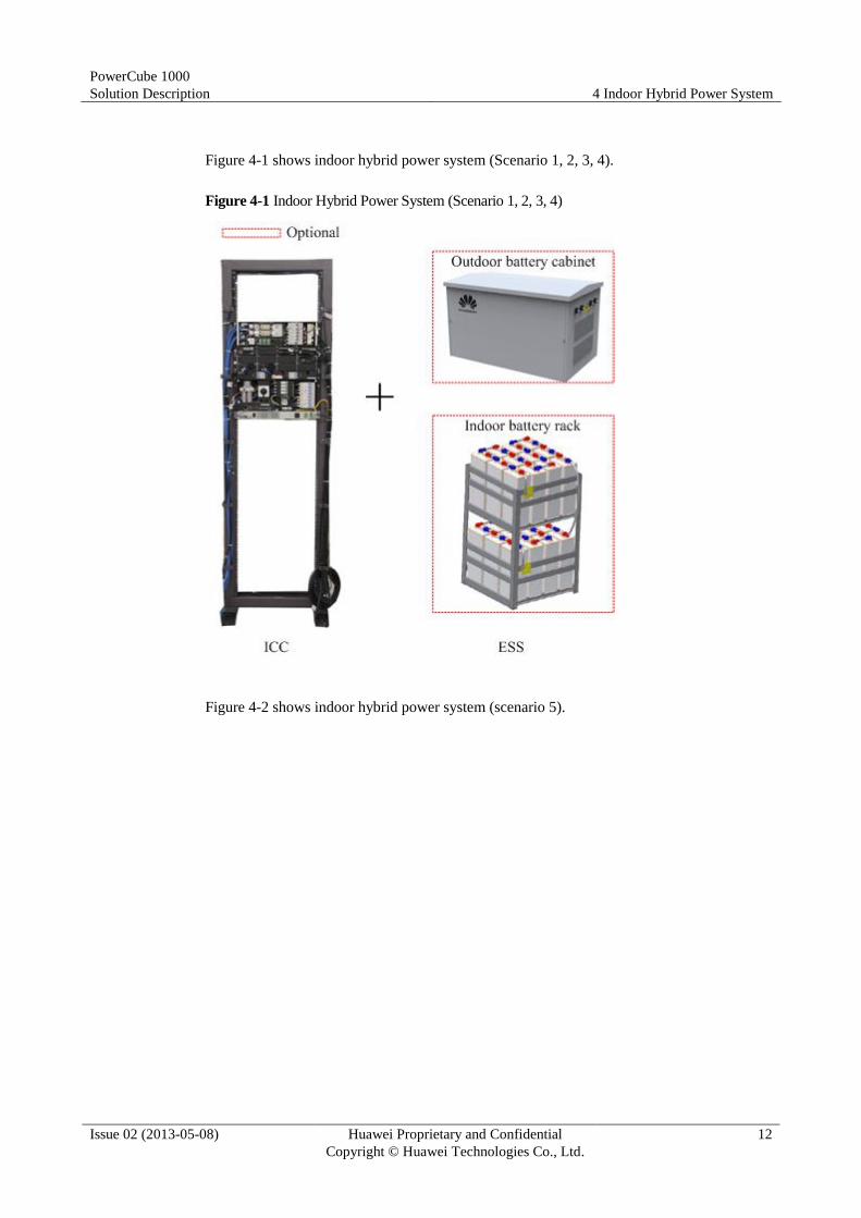
Figure 4-1 shows indoor hybrid power system (Scenario 1, 2, 3, 4).
Figure 4-1 Indoor Hybrid Power System (Scenario 1, 2, 3, 4)
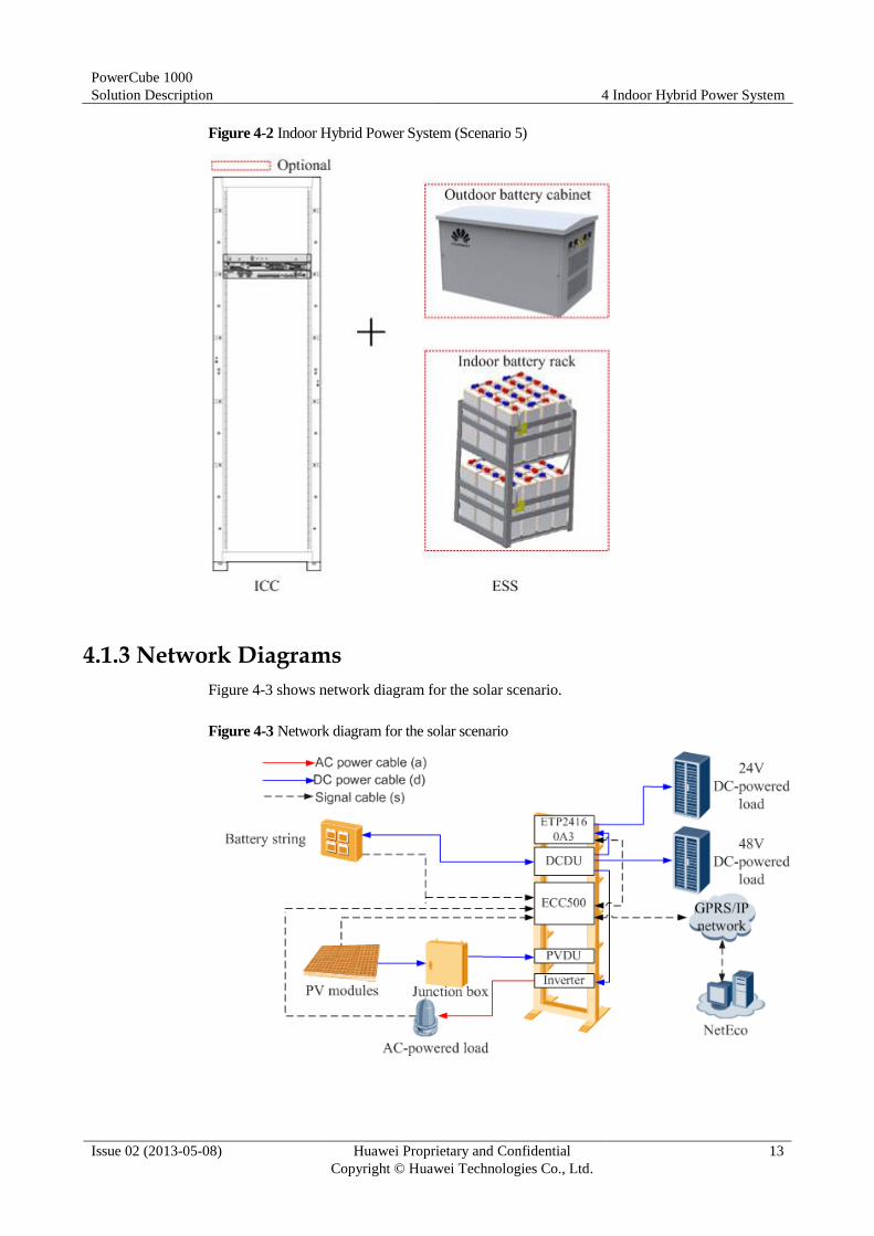
Figure 4-2 shows indoor hybrid power system (scenario 5).
PowerCube 1000
Solution Description 4 Indoor Hybrid Power System
Issue 02 (2013-05-08) Huawei Proprietary and Confidential
Copyright © Huawei Technologies Co., Ltd.
13
Figure 4-2 Indoor Hybrid Power System (Scenario 5)
4.1.3 Network Diagrams
Figure 4-3 shows network diagram for the solar scenario.
Figure 4-3 Network diagram for the solar scenario
PowerCube 1000
Solution Description 4 Indoor Hybrid Power System
Issue 02 (2013-05-08) Huawei Proprietary and Confidential
Copyright © Huawei Technologies Co., Ltd.
14
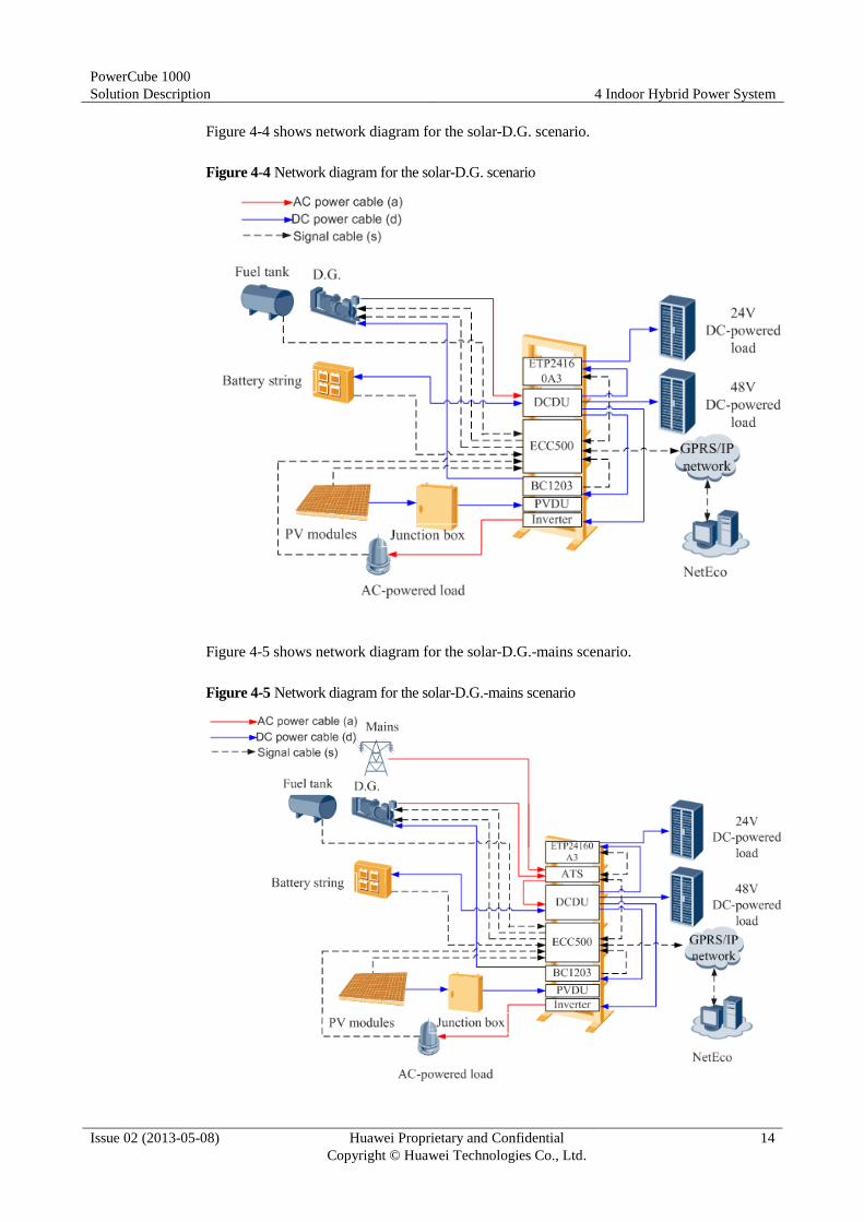
Figure 4-4 shows network diagram for the solar-D.G. scenario.
Figure 4-4 Network diagram for the solar-D.G. scenario
Figure 4-5 shows network diagram for the solar-D.G.-mains scenario.
Figure 4-5 Network diagram for the solar-D.G.-mains scenario
PowerCube 1000
Solution Description 4 Indoor Hybrid Power System
Issue 02 (2013-05-08) Huawei Proprietary and Confidential
Copyright © Huawei Technologies Co., Ltd.
15
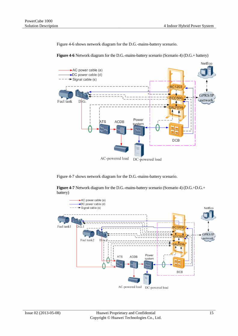
Figure 4-6 shows network diagram for the D.G.-mains-battery scenario.
Figure 4-6 Network diagram for the D.G.-mains-battery scenario (Scenario 4) (D.G.+ battery)
Figure 4-7 shows network diagram for the D.G.-mains-battery scenario.
Figure 4-7 Network diagram for the D.G.-mains-battery scenario (Scenario 4) (D.G.+D.G.+
battery)
PowerCube 1000
Solution Description 4 Indoor Hybrid Power System
Issue 02 (2013-05-08) Huawei Proprietary and Confidential
Copyright © Huawei Technologies Co., Ltd.
16
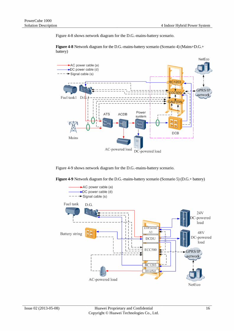
Figure 4-8 shows network diagram for the D.G.-mains-battery scenario.
Figure 4-8 Network diagram for the D.G.-mains-battery scenario (Scenario 4) (Mains+D.G.+
battery)
Figure 4-9 shows network diagram for the D.G.-mains-battery scenario.
Figure 4-9 Network diagram for the D.G.-mains-battery scenario (Scenario 5) (D.G.+ battery)

PowerCube 1000
Solution Description 4 Indoor Hybrid Power System
Issue 02 (2013-05-08) Huawei Proprietary and Confidential
Copyright © Huawei Technologies Co., Ltd.
17
Figure 4-10 shows network diagram for the D.G.-mains-battery scenario.
Figure 4-10 Network diagram for the D.G.-mains-battery scenario (Scenario 5) (D.G.+
battery, D.G.+D.G.+ battery, Mains+D.G.+ battery)
Figure 4-11 shows network diagram for the D.G.-mains-battery scenario.
PowerCube 1000
Solution Description 4 Indoor Hybrid Power System
Issue 02 (2013-05-08) Huawei Proprietary and Confidential
Copyright © Huawei Technologies Co., Ltd.
18
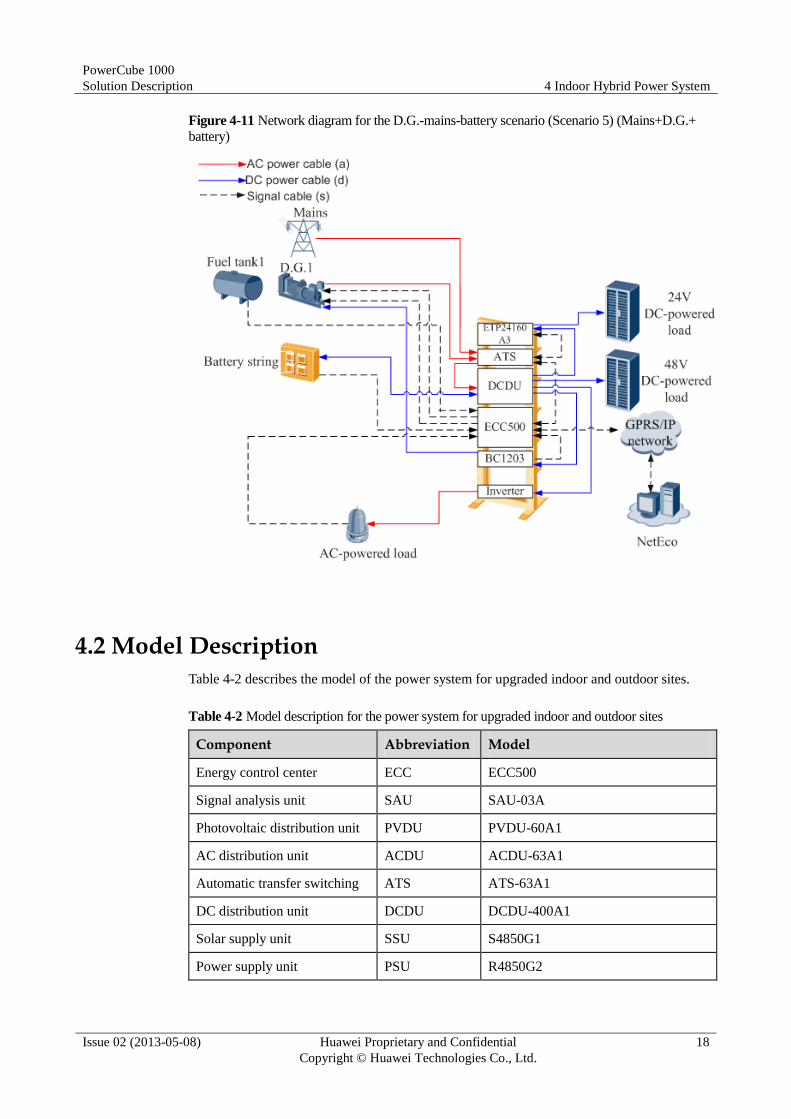
Figure 4-11 Network diagram for the D.G.-mains-battery scenario (Scenario 5) (Mains+D.G.+
battery)
4.2 Model Description
Table 4-2 describes the model of the power system for upgraded indoor and outdoor sites.
Table 4-2 Model description for the power system for upgraded indoor and outdoor sites
Component Abbreviation Model
Energy control center ECC ECC500
Signal analysis unit SAU SAU-03A
Photovoltaic distribution unit PVDU PVDU-60A1
AC distribution unit ACDU ACDU-63A1
Automatic transfer switching ATS ATS-63A1
DC distribution unit DCDU DCDU-400A1
Solar supply unit SSU S4850G1
Power supply unit PSU R4850G2

PowerCube 1000
Solution Description 4 Indoor Hybrid Power System
Issue 02 (2013-05-08) Huawei Proprietary and Confidential
Copyright © Huawei Technologies Co., Ltd.
19
Component Abbreviation Model
Deep cycle battery DCB-A 300Ah, 420 Ah, 490 Ah, and 600 Ah
Solar cycle battery SCB 200 Ah, 300 Ah, 600 Ah
Battery charger BC BC1203 and BC1203D
4.3 Working Modes
Solar Power System
By using a solar controller, the solar power system converts the power from PV modules into
–48 V DC power to supply power for communications equipment and storage batteries.
Solar-D.G. Hybrid Power System
The solar-D.G. hybrid power system uses solar energy and fuel as power sources. Solar
energy is used as the main power source. When solar energy is insufficient and the amount of
electricity in storage batteries drops to the depth of discharge (DOD), the D.G. starts to supply
power.
Solar-D.G.-mains Hybrid Power System
The solar-D.G.-mains hybrid power system uses solar energy, fuel, and mains as power
sources. The solar energy is preferred to supply power. If the solar energy is unavailable and
the amount of electricity in storage batteries drops to the depth of discharge (DOD), the mains
starts to supply power. If the mains becomes abnormal, the D.G. starts to supply power.
D.G.-Mains-Battery Hybrid Power System
The D.G.-mains-battery power system uses fuel and mains as power sources. The mains is
preferred to supply power. When the mains is unavailable and the amount of electricity in
storage batteries drops to the depth of discharge (DOD), the D.G. starts to supply power.
4.4 Open Rack and Cabine
4.4.1 Open Rack
Table 4-3 lists its structural specifications. An open rack is used for installing the ECC500,
SAU-03A, or BC1203 indoors.
Table 4-3 Open rack structural specifications
Item Specifications
Dimensions (H x W x D) 2200 mm x 600 mm x 600 mm
PowerCube 1000
Solution Description 4 Indoor Hybrid Power System
Issue 02 (2013-05-08) Huawei Proprietary and Confidential
Copyright © Huawei Technologies Co., Ltd.
20
Item Specifications
Available height 45 U
Weight About 25kg
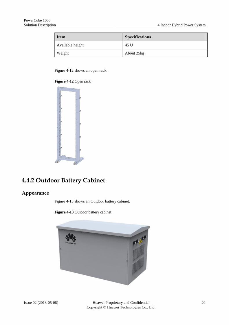
Figure 4-12 shows an open rack.
Figure 4-12 Open rack
4.4.2 Outdoor Battery Cabinet
Appearance
Figure 4-13 shows an Outdoor battery cabinet.
Figure 4-13 Outdoor battery cabinet

PowerCube 1000
Solution Description 4 Indoor Hybrid Power System
Issue 02 (2013-05-08) Huawei Proprietary and Confidential
Copyright © Huawei Technologies Co., Ltd.
21
Functions
The cabinet houses and protects SCBs and DCB-As and provides an appropriate temperature
for the storage batteries inside.
Technical Specifications
Table 4-4 shows technical specifications of the outdoor battery cabinet.
Table 4-4 Technical specifications of the outdoor battery cabinet
Item Specifications
Shape Cuboid
Dimensions (H x W x D) For housing SCBs: 1060 mm x 990 mm x 1650 mm
(39.37 in. x 38.98 in. x 64.96 in.)
For housing gel batteries: 1000 mm x 950 mm x 1500
mm (39.37 in. x 37.40 in. x 59.06 in.)
Color Huawei gray
Weight < 160 kg (352.8 lb)
4.4.3 Indoor Battery Rack
Appearance
Figure 4-14 shows indoor battery rack.
Figure 4-14 Indoor Battery Rack
PowerCube 1000
Solution Description 4 Indoor Hybrid Power System
Issue 02 (2013-05-08) Huawei Proprietary and Confidential
Copyright © Huawei Technologies Co., Ltd.
22
Functions
The cabinet houses DCB-As.
Technical Specifications
Table 4-5 shows technical specifications of the indoor battery rack.
Table 4-5 Technical specifications of the indoor battery rack
Item Specifications
Shape Rack
Dimensions (H x W x D) 1422 mm x 813 mm x 826 mm(include 490Ah battery)
1597 mm x 729 mm x 826 mm(include
300Ah/420Ah/6000Ah battery)
4.5 EPS Components
4.5.1 D.G.
D.G. supplies alternating current (AC) power to site.
A D.G. is reused in this solutions.Detail D.G. information to see D.G. user manual.
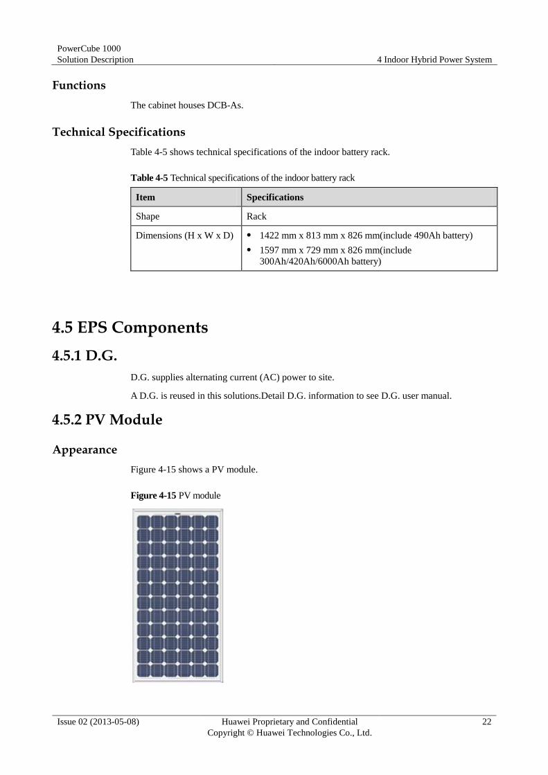
4.5.2 PV Module
Appearance
Figure 4-15 shows a PV module.
Figure 4-15 PV module
PowerCube 1000
Solution Description 4 Indoor Hybrid Power System
Issue 02 (2013-05-08) Huawei Proprietary and Confidential
Copyright © Huawei Technologies Co., Ltd.
23
Functions
A PV module, as an important component for light-to-electricity conversion in the Solar
Power System, supplies power to loads. It is resistant to corrosion, wind, and rain. PV
modules are connected in series or parallel to meet load voltage and current requirements.
Features
A PV module has the following features:
Good light transmission.
Double-layer solar cell, with high circuit reliability.
Long service life (25 years).
Multi-layer polyolefin compressed circuit, which is moisture-proof, well-insulated
and works stably under undervoltage conditions.
Certified by the TUV, Underwriters Laboratory (UL), International Organization for
Standardization (ISO), CE, and International Electrotechnical Commission (IEC).
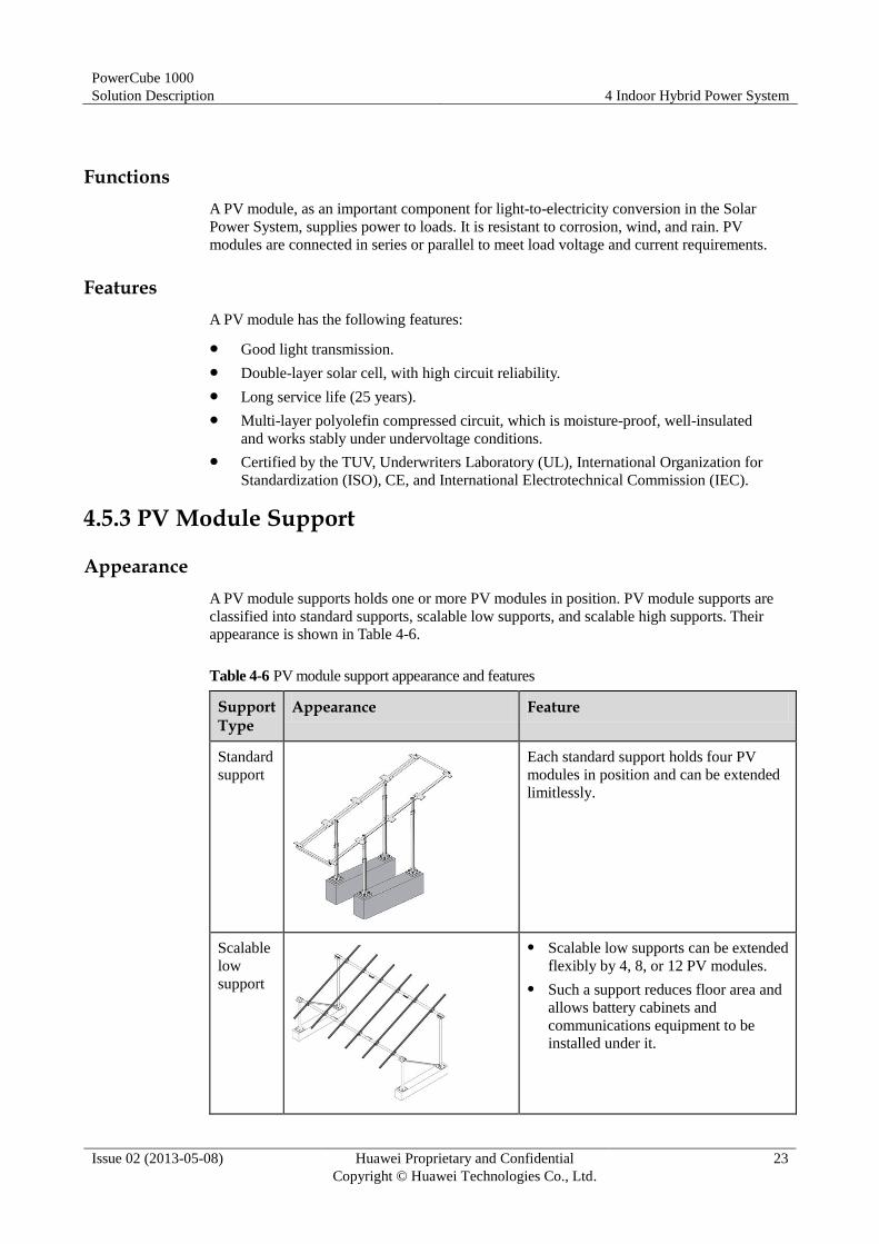
4.5.3 PV Module Support
Appearance
A PV module supports holds one or more PV modules in position. PV module supports are
classified into standard supports, scalable low supports, and scalable high supports. Their
appearance is shown in Table 4-6.
Table 4-6 PV module support appearance and features
Support Type
Appearance Feature
Standard
support
Each standard support holds four PV
modules in position and can be extended
limitlessly.
Scalable
low
support
Scalable low supports can be extended
flexibly by 4, 8, or 12 PV modules.
Such a support reduces floor area and
allows battery cabinets and
communications equipment to be
installed under it.

PowerCube 1000
Solution Description 4 Indoor Hybrid Power System
Issue 02 (2013-05-08) Huawei Proprietary and Confidential
Copyright © Huawei Technologies Co., Ltd.
24
Support Type
Appearance Feature
Scalable
high
support
Scalable low supports can be extended
flexibly by 4, 8, or 12 PV modules.
Such a support reduces floor area and
allows battery cabinets and
communications equipment to be
installed under it.
Such a support features optimal theft
prevention compared with the other
types of supports.
Features
A PV module support has the following features:
Is designed to prevent theft and secured by dedicated antitheft bolts.
Can be extended flexibly.
Is safe and reliable, withstanding the wind speed of 144 km/h.
Is easy to install and remove.
4.5.4 SJB
Appearance
Figure 4-16 shows a standard solar junction box, Figure 4-17 shows a enhanced solar junction
box.
Figure 4-16 Standard solar junction box

PowerCube 1000
Solution Description 4 Indoor Hybrid Power System
Issue 02 (2013-05-08) Huawei Proprietary and Confidential
Copyright © Huawei Technologies Co., Ltd.
25
Figure 4-17 Enhanced solar junction box
Functions
A junction box allows outdoor PV arrays to be connected in parallel. It consists of input and
output wiring terminals. To decrease cable voltage drop and facilitate installation, multiple
junction boxes can be used based on site requirements.
4.6 ICC Components
4.6.1 ECC500
Appearance
Figure 4-18 shows ECC500 configurations.
Figure 4-18 ECC500
(1) Main control board (2) Extension DO board (3) GPRS board
(4) Extension IO board (5) D.G. IO board (6) Basic IO board
Functions
The ECC500 schedules energy. The Main control board monitors other PowerCube
components by working with the basic I/O module, general packet radio service (GPRS)
module, and D.G. control module.
Features
The ECC500 has the following features:

PowerCube 1000
Solution Description 4 Indoor Hybrid Power System
Issue 02 (2013-05-08) Huawei Proprietary and Confidential
Copyright © Huawei Technologies Co., Ltd.
26
Performs comprehensive power management, battery management, and intelligent
control device management locally or remotely. For example, it can communicate with
power supply units (PSUs) over RS485 or CAN ports, communicate with a host over an
RS485 or RS232 port, and monitor equipment remotely over a 10/100M autonegotation
Ethernet port.
Reports the data collected by the water sensor, smoke sensor, door status sensor, ambient
temperature and humidity sensor, battery temperature sensor over reserved analog
parameter ports and dry contacts.
Monitors power distribution and reports alarms.
Displays the AC status and DC status of the power system as well as the operating
parameters, operating status, alarm information, preset parameters, and control
parameters of modules and storage batteries on the liquid crystal display (LCD) in real
time.
Copies parameter settings from a USB flash drive to the ECC during site deployment.
4.6.2 SAU-03A
Appearance
Figure 4-19 shows an SAU-03A.
Figure 4-19 SAU-03A
Functions
The SAU-03A calculates the AC power consumption on each route based on the detected AC
voltages and currents, and sends the consumption data to the ECC. It is also under the control
of the ECC500. The SAU-03A can work as an AC meter in a Mini-shelter.
Features
An SAU-03A has the following features:
Detects two three-phase, four-wire AC voltages.
Detects two three-phase AC currents.
Detects the voltages of two battery strings.
Detects the currents of two battery strings.
Provides two cascaded CAN communications ports that share one CAN bus, and
provides one four-wire RS485 port.
Provides one RS232 port.
Provides one 4-pin DIP switch, with two pins used for setting a 120-ohm resistor for the
CAN port and two pins used for setting the address for the CAN port.
Provides two routes for measuring AC consumption and frequencies.

PowerCube 1000
Solution Description 4 Indoor Hybrid Power System
Issue 02 (2013-05-08) Huawei Proprietary and Confidential
Copyright © Huawei Technologies Co., Ltd.
27
4.6.3 ATS-63A1
Appearance
Figure 4-20 shows an ATS-63A1.
Figure 4-20 ATS-63A1
Function
The ATS is an automatic switch system integrating control modules and power distribution
modules. It supports inputs from the two power sources and switches the power inputs from
diesel generator (D.G.) 1 and the mains or from D.G. 1 and D.G. 2. The power source can
switch to D.G. 1 by turning the bypass switch. The ATS has the following functions:
AC power distribution: The ATS provides one AC output, one 10 A AC output, and one
maintenance socket output (optional).
Bypass: The ATS provides a bypass switch, over which power source can switch
to D.G.1.
Real-time monitoring: The ATS monitors the voltage, current, frequency, and power of
three-phase outputs.
Protection: The ATS is protected against overvoltage, undervolatge,
Alarm: open-phase of the D.G. and mains supply.
Communicates with the ECC500.
Working Mode
The ATS-63A1 can be operated automatically(Auto) or manually(Bypass).
4.6.4 ACDU-63A1
Appearance
Figure 4-21 shows an ACDU-63A1.

PowerCube 1000
Solution Description 4 Indoor Hybrid Power System
Issue 02 (2013-05-08) Huawei Proprietary and Confidential
Copyright © Huawei Technologies Co., Ltd.
28
Figure 4-21 ACDU-63A1 panel
Functions Provides one three-phase 220 V AC input and one 3-pole 63 A AC circuit breaker.
(Optional) Provides one 10 A European standard maintenance socket with a ground fault
circuit interrupter (GFCI).
Provides one three-phase 220 V AC output and one 3-pole 63 A AC circuit breaker.
Provides one single-phase 220 V AC output and one 1-pole 16 A AC circuit breaker.
Performs AC surge protection:
Differential mode: 20 kA.
Common mode: 40 kA.
Generates alarms over dry contacts.
4.6.5 DCDU-400A1
Appearance
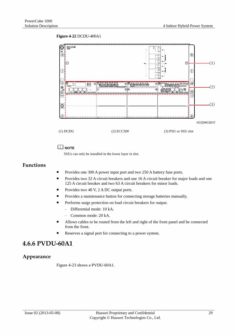
The DCDU-400A1 consists of a power distribution subrack and an ECC500. Figure 4-22
shows an DCDU-400A1. The DCDU-400A1 can be configured with PSUs and SSUs.
PowerCube 1000
Solution Description 4 Indoor Hybrid Power System
Issue 02 (2013-05-08) Huawei Proprietary and Confidential
Copyright © Huawei Technologies Co., Ltd.
29
Figure 4-22 DCDU-400A1
(1) DCDU (2) ECC500 (3) PSU or SSU slot
SSUs can only be installed in the lower layer in slot.
Functions Provides one 300 A power input port and two 250 A battery fuse ports.
Provides two 32 A circuit breakers and one 16 A circuit breaker for major loads and one
125 A circuit breaker and two 63 A circuit breakers for minor loads.
Provides two 48 V, 2 A DC output ports.
Provides a maintenance button for connecting storage batteries manually.
Performs surge protection on load circuit breakers for output.
− Differential mode: 10 kA.
− Common mode: 20 kA.
Allows cables to be routed from the left and right of the front panel and be connected
from the front.
Reserves a signal port for connecting to a power system.
4.6.6 PVDU-60A1
Appearance
Figure 4-23 shows a PVDU-60A1.
NOTE

PowerCube 1000
Solution Description 4 Indoor Hybrid Power System
Issue 02 (2013-05-08) Huawei Proprietary and Confidential
Copyright © Huawei Technologies Co., Ltd.
30
Figure 4-23 PVDU-60A1
Functions
The PVDU-60A1 collects power from PV modules and supplies power to the DCDU-400A1.
The PVDU-60A1 provides four wiring terminals to connect to the negative input terminals of
PV modules. It also provides four input circuit breakers to connect to the positive input
terminals of PV modules.
4.6.7 S4850G1
Appearance
The S4850G1 panel provides a Run indicator, a Protection indicator, and a Fault indicator.
Figure 4-24 shows an S4850G1.
Figure 4-24 S4850G1
Functions
The S4850G1 is a DC-DC converter that uses maximum power point track (MPPT)
technology. It tracks the highest solar power point based on the output features of PV modules
to maximize the use of solar energy.
Features
The S4850G1 has the following features:
Is 1 U high, 2.5 U wide, fan-cooled, and hot-swappable.
Works at –20°C to +75°C (power derated above 55°C).
Maximum input power: 3100 W.
PowerCube 1000
Solution Description 4 Indoor Hybrid Power System
Issue 02 (2013-05-08) Huawei Proprietary and Confidential
Copyright © Huawei Technologies Co., Ltd.
31
Output voltage: 43.2–58 V DC.
Rated voltage: 53.5 V DC.
Maximum output power: 3000 W.
Is protected against input reverse connection.
4.6.8 PSU
Appearance
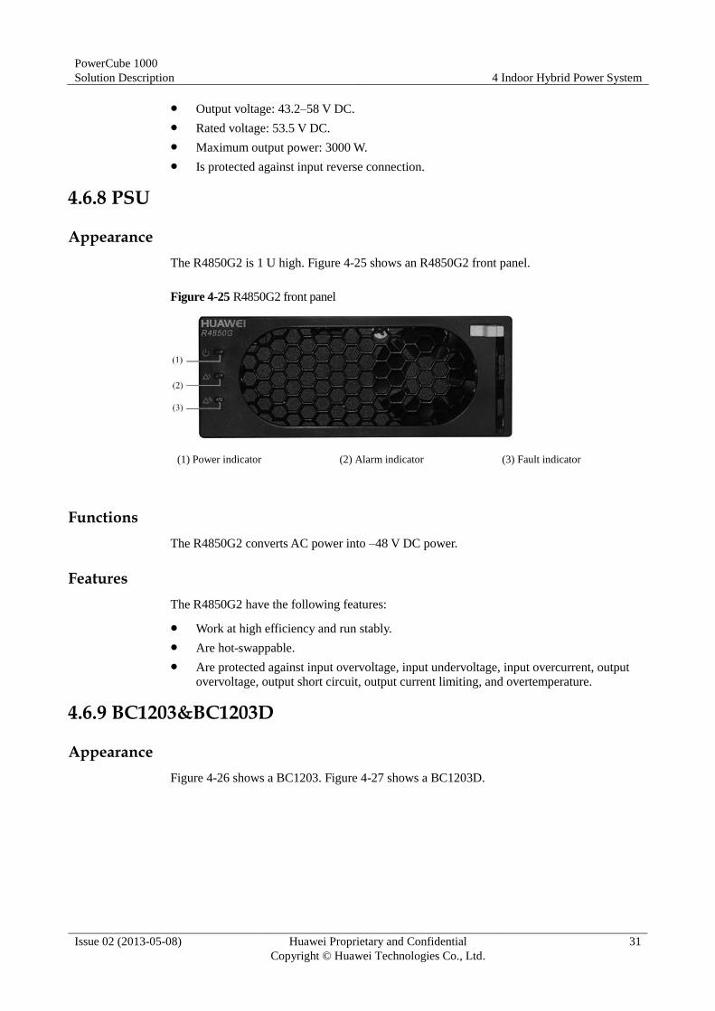
The R4850G2 is 1 U high. Figure 4-25 shows an R4850G2 front panel.
Figure 4-25 R4850G2 front panel
(1) Power indicator (2) Alarm indicator (3) Fault indicator
Functions
The R4850G2 converts AC power into –48 V DC power.
Features
The R4850G2 have the following features:
Work at high efficiency and run stably.
Are hot-swappable.
Are protected against input overvoltage, input undervoltage, input overcurrent, output
overvoltage, output short circuit, output current limiting, and overtemperature.
4.6.9 BC1203&BC1203D
Appearance
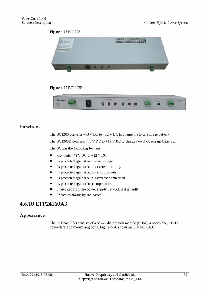
Figure 4-26 shows a BC1203. Figure 4-27 shows a BC1203D.
PowerCube 1000
Solution Description 4 Indoor Hybrid Power System
Issue 02 (2013-05-08) Huawei Proprietary and Confidential
Copyright © Huawei Technologies Co., Ltd.
32
Figure 4-26 BC1203
Figure 4-27 BC1203D
Functions
The BC1203 converts –48 V DC to +12 V DC to charge the D.G. storage battery.
The BC1203D converts –48 V DC to +12 V DC to charge two D.G. storage batterys.
The BC has the following features:
Converts –48 V DC to +12 V DC.
Is protected against input overvoltage.
Is protected against output current limiting.
Is protected against output short circuits.
Is protected against output reverse connection.
Is protected against overtemperature.
Is isolated from the power supply network if it is faulty.
Indicates alarms by indicators.
4.6.10 ETP24160A3
Appearance
The ETP24160A3 consists of a power distribution module (PDM), a backplane, DC-DC
converters, and monitoring ports. Figure 4-28 shows an ETP24160A3.

PowerCube 1000
Solution Description 4 Indoor Hybrid Power System
Issue 02 (2013-05-08) Huawei Proprietary and Confidential
Copyright © Huawei Technologies Co., Ltd.
33
Figure 4-28 ETP24160A3
(1) Load circuit breaker F1 (2) Load circuit
breaker F2
(3) Load circuit breaker F3 (4) Load circuit
breaker F4
(5) Load circuit breaker F5 (6) Load circuit
breaker F6
(7) DC input port on the
DC-DC converter
(8) DC-DC converter
Functions
The ETP24160A3 converts –48 V DC into +24 V DC, distributes power, and reports alarms.
Features
The ETP24160A3 has the following features:
Converts –48 V DC into +24 V DC.
Provides four 100 A and two 32 A power supplies for loads.
Provides two dry contacts for reporting alarms.
Uploads operating information such as the voltage and current as well as DC-DC
converter fault alarms to the main control unit (MCU) over the CAN. The output voltage
range of the ETP24160A3 is set on the MCU.
Allows you to query component information recorded on electronic labels.
DC-DC converters are hot-swappable.
Can be maintained from the front.
The highest efficiency is 92%.
4.6.11 Inverter
Appearance
Figure 4-29 shows the front panels of two types of inverters.

PowerCube 1000
Solution Description 4 Indoor Hybrid Power System
Issue 02 (2013-05-08) Huawei Proprietary and Confidential
Copyright © Huawei Technologies Co., Ltd.
34
Figure 4-29 Inverter front panel
(1) DC input port (2) Switch (3) Air exhaust vents
(4) SPD (5) All-purpose output socket (6) Indicator
(7) Dry contact (8) AC input and output terminal
Functions
The inverter converts DC input into AC output.
Technical Specifications
Table 4-7 lists the inverter technical specifications.
Table 4-7 Inverter technical specifications
Item Specifications
Rated capacity 1000 VA/700 W
AC
input
Rated voltage 230 V AC
Rated frequency 45–55 Hz
DC
input
Rated voltage 48 V DC
Rated voltage 20 A
AC
output
Output voltage 220 V AC (tolerance: ±3%)
Output frequency 50 Hz (tolerance: ±1%)
Output mode One AC output wiring terminal and one all-purpose socket
Dimensions (H x W x D) 43.5 mm x 440 mm x 286 mm
4.7 ESS Components
4.7.1 DCB-A
Appearance
Figure 4-30 shows a DCB-A.

PowerCube 1000
Solution Description 4 Indoor Hybrid Power System
Issue 02 (2013-05-08) Huawei Proprietary and Confidential
Copyright © Huawei Technologies Co., Ltd.
35
Figure 4-30 DCB-A
Features
A DCB-A has the following features:
Can be charged in a large current.
The low self discharge ratio enables DCB-As to be used for two years at 25°C and
restores the rated capacity by 100%.
Can be charged and discharged 2000 times at 25°C if the DOD is 60%.
4.7.2 SCB
Appearance
Figure 4-31 shows an SCB.

PowerCube 1000
Solution Description 4 Indoor Hybrid Power System
Issue 02 (2013-05-08) Huawei Proprietary and Confidential
Copyright © Huawei Technologies Co., Ltd.
36
Figure 4-31 SCB
Features
SCBs are designed for the scenarios where solar energy is used and provide good energy
circulation. They have the following features:
Is applicable to locations at most 4000 meters above sea level.
Can be charged and discharged 1500 times at 35°C if the DOD is 30%.
Has a voltage of 2 V and a capacity of 200 Ah, 300 Ah, 600 Ah, or 800 Ah.
Can be installed in an outdoor battery cabinet.
PowerCube 1000
Solution Description 5 Outdoor Hybrid Power System
Issue 02 (2013-05-08) Huawei Proprietary and Confidential
Copyright © Huawei Technologies Co., Ltd.
37
5 Outdoor Hybrid Power System
5.1 Application Scenarios and Configurations
5.1.1 Application Scenarios
The power system for upgraded outdoor sites applies to the following scenarios:
− Solar power system
− Solar-D.G. hybrid power system
− Solar-D.G.- mains hybrid power system
− D.G.-mains-battery hybrid power system
Solar-D.G. hybrid power system and Solar-D.G.- mains hybrid power system are reused
EPS.
In D.G.-mains-battery hybrid power system, power system an be reused.
D.G.-mains-battery hybrid power system contains three working modes
− D.G.+ battery alternate working mode
− D.G.+D.G.+ battery alternate working mode
− Mains+D.G.+ battery alternate working mode
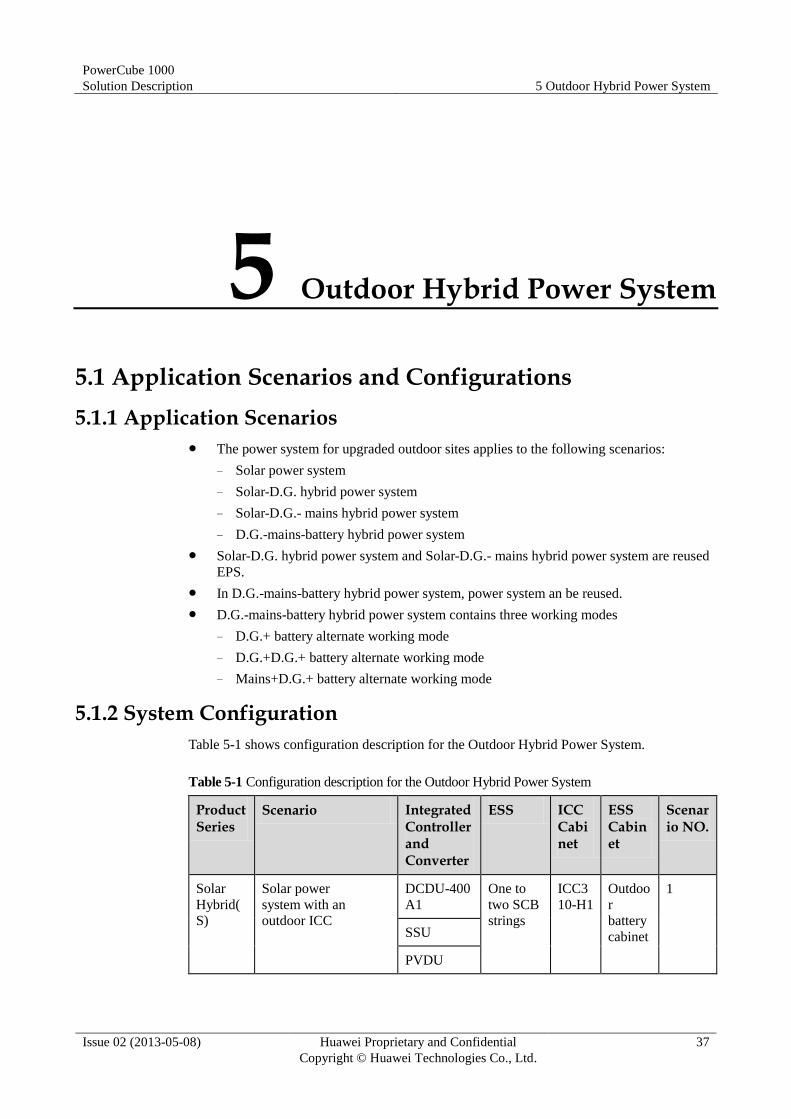
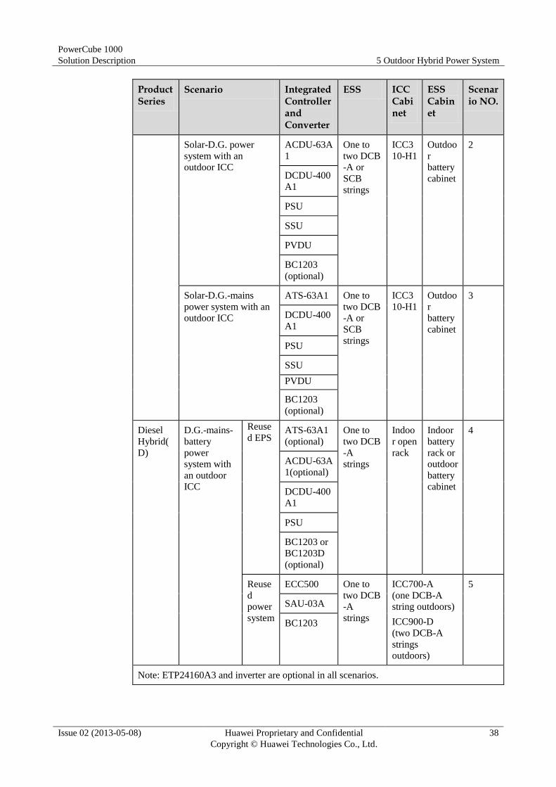
5.1.2 System Configuration
Table 5-1 shows configuration description for the Outdoor Hybrid Power System.
Table 5-1 Configuration description for the Outdoor Hybrid Power System
Product Series
Scenario Integrated Controller and Converter
ESS ICC Cabinet
ESS Cabinet
Scenario NO.
Solar
Hybrid(
S)
Solar power
system with an
outdoor ICC
DCDU-400
A1
One to
two SCB
strings
ICC3
10-H1
Outdoo
r
battery
cabinet
1
SSU
PVDU
PowerCube 1000
Solution Description 5 Outdoor Hybrid Power System
Issue 02 (2013-05-08) Huawei Proprietary and Confidential
Copyright © Huawei Technologies Co., Ltd.
38
Product Series
Scenario Integrated Controller and Converter
ESS ICC Cabinet
ESS Cabinet
Scenario NO.
Solar-D.G. power
system with an
outdoor ICC
ACDU-63A
1
One to
two DCB
-A or
SCB
strings
ICC3
10-H1
Outdoo
r
battery
cabinet
2
DCDU-400
A1
PSU
SSU
PVDU
BC1203
(optional)
Solar-D.G.-mains
power system with an
outdoor ICC
ATS-63A1 One to
two DCB
-A or
SCB
strings
ICC3
10-H1
Outdoo
r
battery
cabinet
3
DCDU-400
A1
PSU
SSU
PVDU
BC1203
(optional)
Diesel
Hybrid(
D)
D.G.-mains-
battery
power
system with
an outdoor
ICC
Reuse
d EPS ATS-63A1
(optional)
One to
two DCB
-A
strings
Indoo
r open
rack
Indoor
battery
rack or
outdoor
battery
cabinet
4
ACDU-63A
1(optional)
DCDU-400
A1
PSU
BC1203 or
BC1203D
(optional)
Reuse
d
power
system
ECC500 One to
two DCB
-A
strings
ICC700-A
(one DCB-A
string outdoors)
ICC900-D
(two DCB-A
strings
outdoors)
5
SAU-03A
BC1203
Note: ETP24160A3 and inverter are optional in all scenarios.
PowerCube 1000
Solution Description 5 Outdoor Hybrid Power System
Issue 02 (2013-05-08) Huawei Proprietary and Confidential
Copyright © Huawei Technologies Co., Ltd.
39
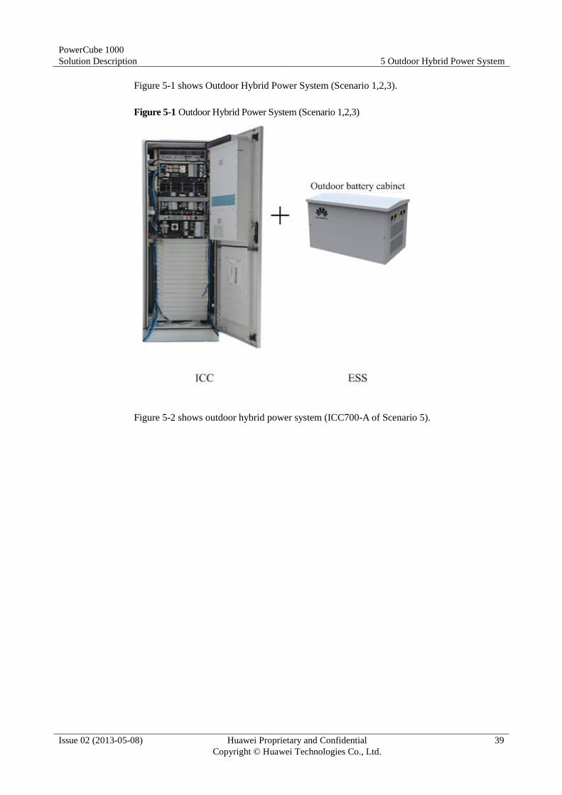
Figure 5-1 shows Outdoor Hybrid Power System (Scenario 1,2,3).
Figure 5-1 Outdoor Hybrid Power System (Scenario 1,2,3)
Figure 5-2 shows outdoor hybrid power system (ICC700-A of Scenario 5).

PowerCube 1000
Solution Description 5 Outdoor Hybrid Power System
Issue 02 (2013-05-08) Huawei Proprietary and Confidential
Copyright © Huawei Technologies Co., Ltd.
40
Figure 5-2 Outdoor Hybrid Power System (ICC700-A of Scenario 5)
Figure 5-3 shows outdoor hybrid power system (ICC900-D of Scenario 5).
Figure 5-3 Outdoor Hybrid Power System (ICC900-D of Scenario 5)
PowerCube 1000
Solution Description 5 Outdoor Hybrid Power System
Issue 02 (2013-05-08) Huawei Proprietary and Confidential
Copyright © Huawei Technologies Co., Ltd.
41
5.1.3 Network Diagrams
See 4.1.3 Network Diagrams.
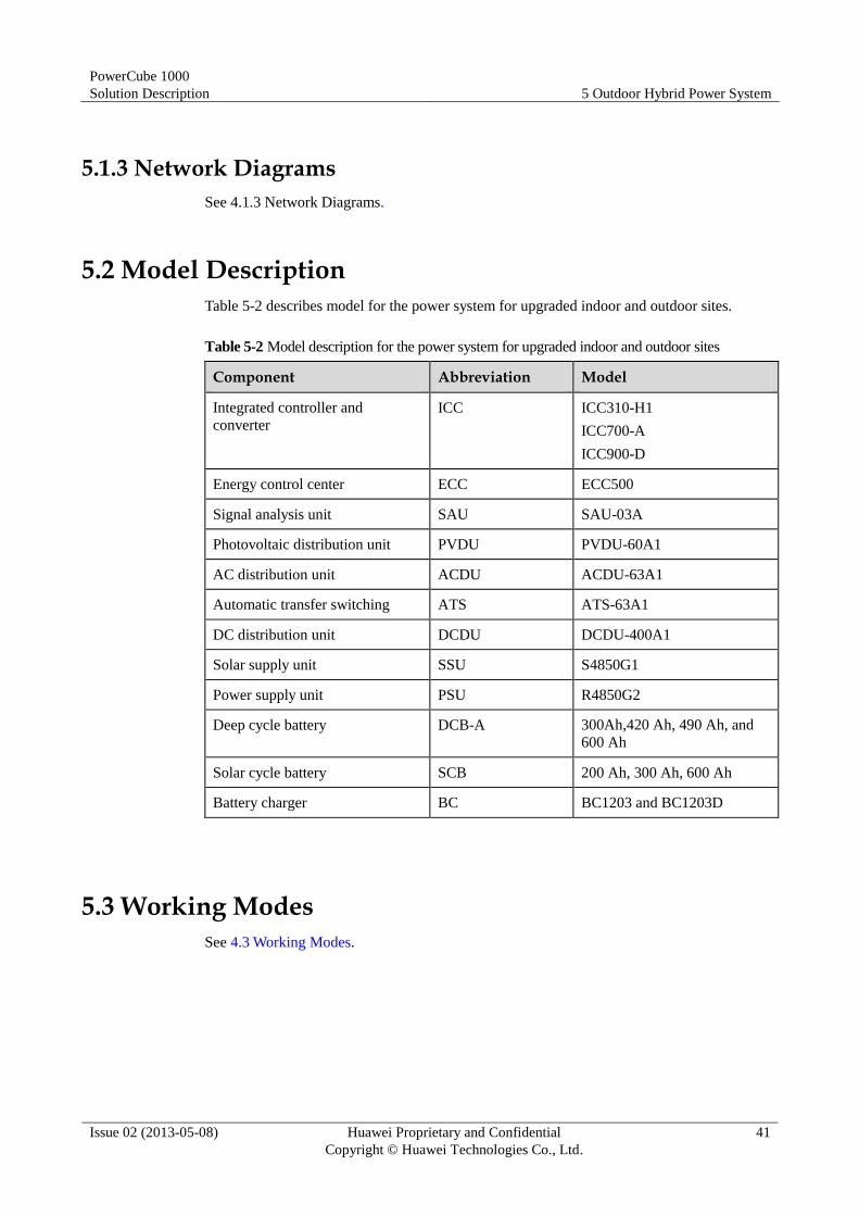
5.2 Model Description
Table 5-2 describes model for the power system for upgraded indoor and outdoor sites.
Table 5-2 Model description for the power system for upgraded indoor and outdoor sites
Component Abbreviation Model
Integrated controller and
converter
ICC ICC310-H1
ICC700-A
ICC900-D
Energy control center ECC ECC500
Signal analysis unit SAU SAU-03A
Photovoltaic distribution unit PVDU PVDU-60A1
AC distribution unit ACDU ACDU-63A1
Automatic transfer switching ATS ATS-63A1
DC distribution unit DCDU DCDU-400A1
Solar supply unit SSU S4850G1
Power supply unit PSU R4850G2
Deep cycle battery DCB-A 300Ah,420 Ah, 490 Ah, and
600 Ah
Solar cycle battery SCB 200 Ah, 300 Ah, 600 Ah
Battery charger BC BC1203 and BC1203D
5.3 Working Modes
See 4.3 Working Modes.

PowerCube 1000
Solution Description 5 Outdoor Hybrid Power System
Issue 02 (2013-05-08) Huawei Proprietary and Confidential
Copyright © Huawei Technologies Co., Ltd.
42
5.4 Cabinets
5.4.1 ICC700-A
Table 5-3 lists the ICC700-A technical specifications. Figure 5-4 shows the ICC700-A
exterior.
Table 5-3 ICC700-A technical specifications
Item Specifications
Dimensions (H x W x D, including the
base)
2110 mm x 900 mm x 935 mm
Maintenance mode Maintained from the front
Temperature control unit (TCU) DC air conditioner
Internal installation space 40 U
Protection level IP55
Weight About 250 kg
Figure 5-4 ICC700-A exterior
PowerCube 1000
Solution Description 5 Outdoor Hybrid Power System
Issue 02 (2013-05-08) Huawei Proprietary and Confidential
Copyright © Huawei Technologies Co., Ltd.
43
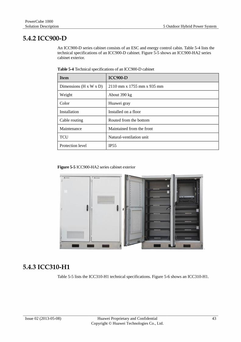
5.4.2 ICC900-D
An ICC900-D series cabinet consists of an ESC and energy control cabin. Table 5-4 lists the
technical specifications of an ICC900-D cabinet. Figure 5-5 shows an ICC900-HA2 series
cabinet exterior.
Table 5-4 Technical specifications of an ICC900-D cabinet
Item ICC900-D
Dimensions (H x W x D) 2110 mm x 1755 mm x 935 mm
Weight About 390 kg
Color Huawei gray
Installation Installed on a floor
Cable routing Routed from the bottom
Maintenance Maintained from the front
TCU Natural-ventilation unit
Protection level IP55
Figure 5-5 ICC900-HA2 series cabinet exterior
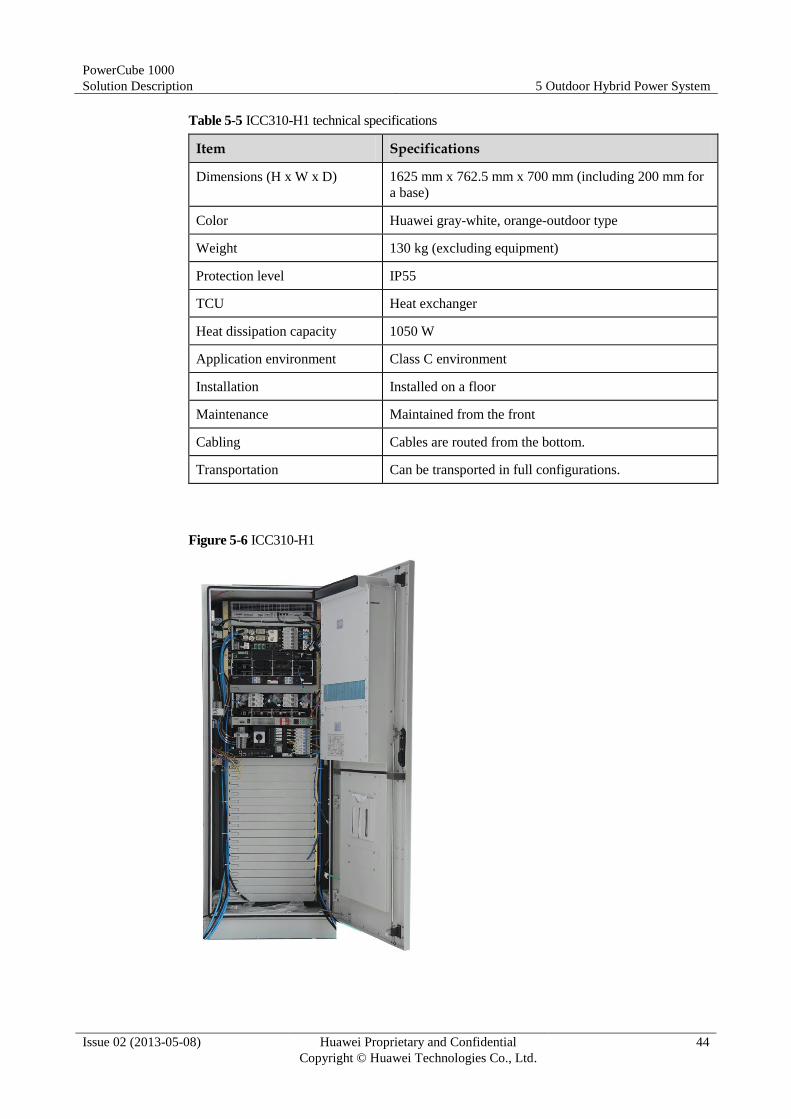
5.4.3 ICC310-H1
Table 5-5 lists the ICC310-H1 technical specifications. Figure 5-6 shows an ICC310-H1.
PowerCube 1000
Solution Description 5 Outdoor Hybrid Power System
Issue 02 (2013-05-08) Huawei Proprietary and Confidential
Copyright © Huawei Technologies Co., Ltd.
44
Table 5-5 ICC310-H1 technical specifications
Item Specifications
Dimensions (H x W x D) 1625 mm x 762.5 mm x 700 mm (including 200 mm for
a base)
Color Huawei gray-white, orange-outdoor type
Weight 130 kg (excluding equipment)
Protection level IP55
TCU Heat exchanger
Heat dissipation capacity 1050 W
Application environment Class C environment
Installation Installed on a floor
Maintenance Maintained from the front
Cabling Cables are routed from the bottom.
Transportation Can be transported in full configurations.
Figure 5-6 ICC310-H1

PowerCube 1000
Solution Description 5 Outdoor Hybrid Power System
Issue 02 (2013-05-08) Huawei Proprietary and Confidential
Copyright © Huawei Technologies Co., Ltd.
45
5.4.4 Outdoor Battery Cabinet
See 4.4.2 Outdoor Battery Cabinet.
5.5 ICC Components
See 4.6 ICC Components.
5.6 ESS Components
See 4.7 ESS.
PowerCube 1000
Solution Description 6 Co-site Hybrid Power System
Issue 02 (2013-05-08) Huawei Proprietary and Confidential
Copyright © Huawei Technologies Co., Ltd.
46
6 Co-site Hybrid Power System
6.1 Application Scenarios and Configurations
6.1.1 Application Scenarios
The Co-site hybrid power system to the following scenarios:
Solar-D.G. scenario, where the solar-D.G. hybrid power system is used
Solar-D.G.-mains scenario, where the solar-D.G.- mains hybrid power system is used
D.G.-mains-battery scenario, where the D.G.-mains-battery hybrid power system is used.
The hybrid power system for outdoor co-sties can be shared by a maximum of four operators.
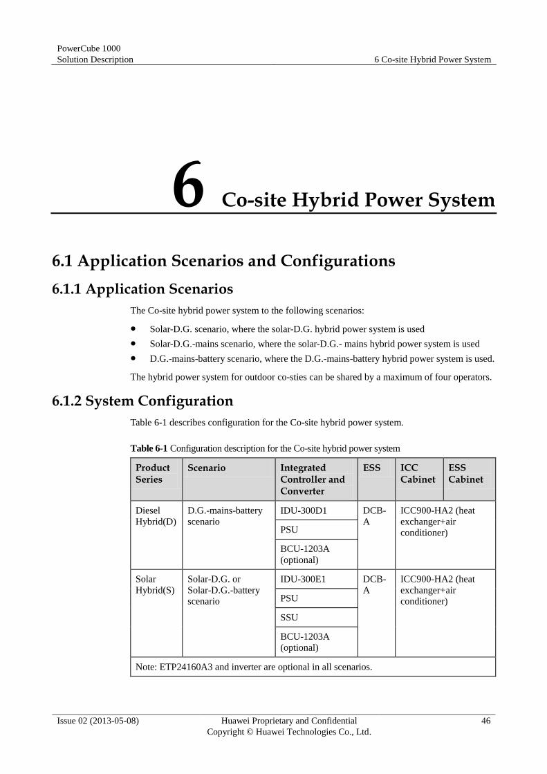
6.1.2 System Configuration
Table 6-1 describes configuration for the Co-site hybrid power system.
Table 6-1 Configuration description for the Co-site hybrid power system
Product Series
Scenario Integrated Controller and Converter
ESS ICC Cabinet
ESS Cabinet
Diesel
Hybrid(D)
D.G.-mains-battery
scenario
IDU-300D1 DCB-
A
ICC900-HA2 (heat
exchanger+air
conditioner) PSU
BCU-1203A
(optional)
Solar
Hybrid(S)
Solar-D.G. or
Solar-D.G.-battery
scenario
IDU-300E1 DCB-
A
ICC900-HA2 (heat
exchanger+air
conditioner) PSU
SSU
BCU-1203A
(optional)
Note: ETP24160A3 and inverter are optional in all scenarios.
PowerCube 1000
Solution Description 6 Co-site Hybrid Power System
Issue 02 (2013-05-08) Huawei Proprietary and Confidential
Copyright © Huawei Technologies Co., Ltd.
47
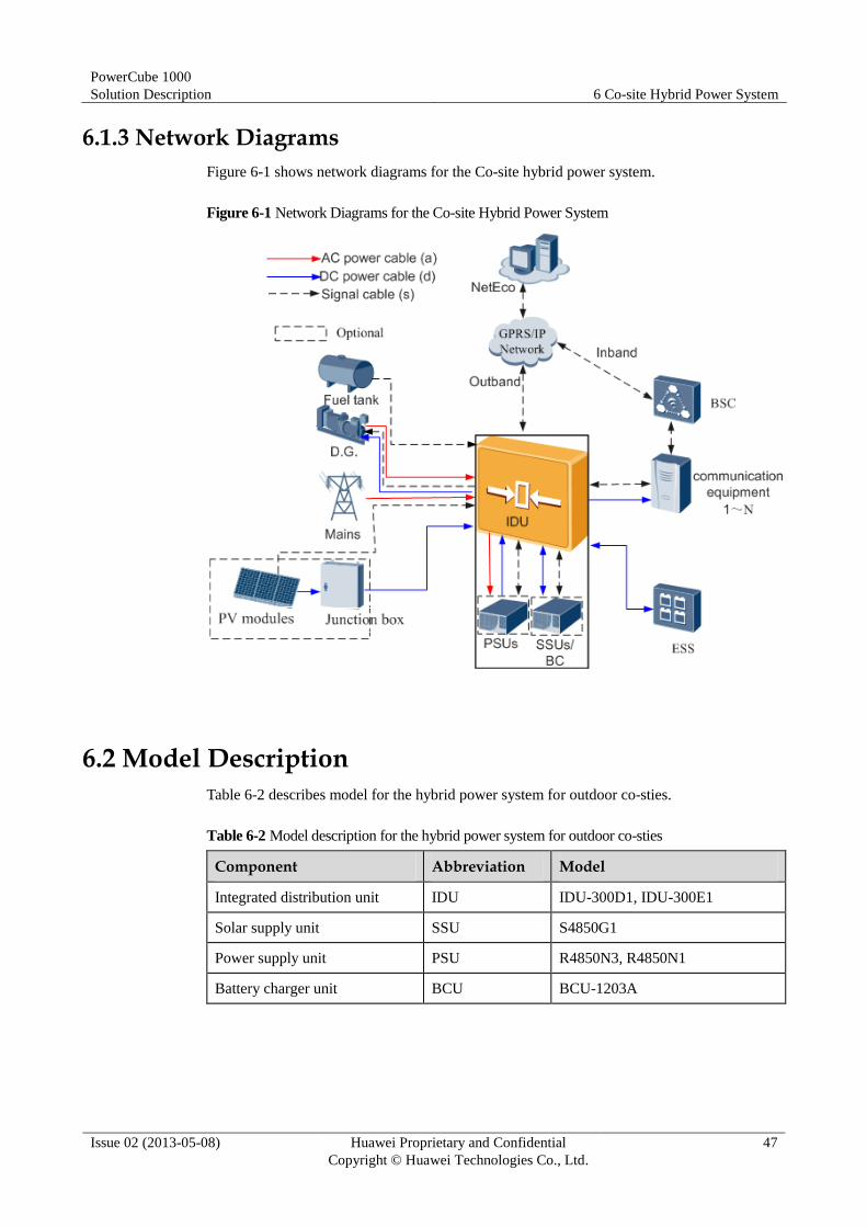
6.1.3 Network Diagrams
Figure 6-1 shows network diagrams for the Co-site hybrid power system.
Figure 6-1 Network Diagrams for the Co-site Hybrid Power System
6.2 Model Description
Table 6-2 describes model for the hybrid power system for outdoor co-sties.
Table 6-2 Model description for the hybrid power system for outdoor co-sties
Component Abbreviation Model
Integrated distribution unit IDU IDU-300D1, IDU-300E1
Solar supply unit SSU S4850G1
Power supply unit PSU R4850N3, R4850N1
Battery charger unit BCU BCU-1203A
PowerCube 1000
Solution Description 6 Co-site Hybrid Power System
Issue 02 (2013-05-08) Huawei Proprietary and Confidential
Copyright © Huawei Technologies Co., Ltd.
48
6.3 Working Modes
See 4.3 Working Modes.
6.4 Cabinet
6.4.1 ICC900-HA2
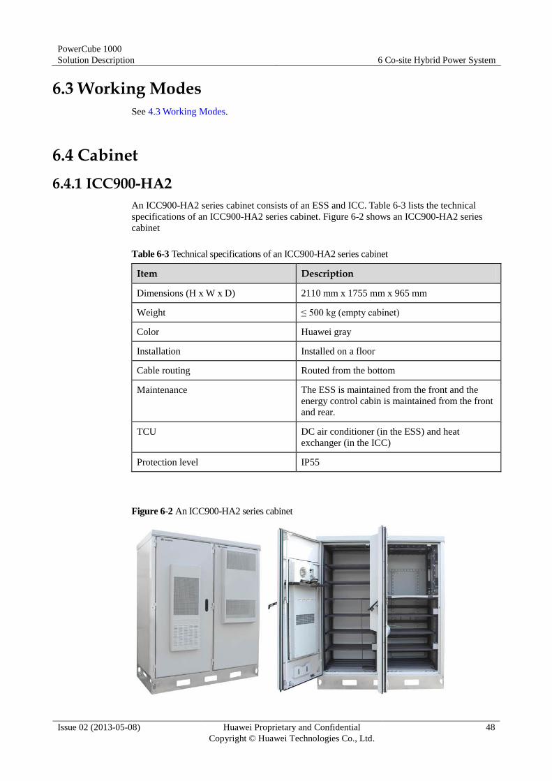
An ICC900-HA2 series cabinet consists of an ESS and ICC. Table 6-3 lists the technical
specifications of an ICC900-HA2 series cabinet. Figure 6-2 shows an ICC900-HA2 series
cabinet
Table 6-3 Technical specifications of an ICC900-HA2 series cabinet
Item Description
Dimensions (H x W x D) 2110 mm x 1755 mm x 965 mm
Weight ≤ 500 kg (empty cabinet)
Color Huawei gray
Installation Installed on a floor
Cable routing Routed from the bottom
Maintenance The ESS is maintained from the front and the
energy control cabin is maintained from the front
and rear.
TCU DC air conditioner (in the ESS) and heat
exchanger (in the ICC)
Protection level IP55
Figure 6-2 An ICC900-HA2 series cabinet

PowerCube 1000
Solution Description 6 Co-site Hybrid Power System
Issue 02 (2013-05-08) Huawei Proprietary and Confidential
Copyright © Huawei Technologies Co., Ltd.
49
6.5 Main Components
6.5.1 IDU
Appearance
An IDU integrates the functions of the ACDU, DCDU, ATS, and PV module (optional), and
reserves space for the ECC500, SSU, and PSU.
Figure 6-3 shows an IDU.
Figure 6-3 IDU
Configurations
Table 6-4 describes the IDU configuration.
Table 6-4 IDU configuration description
Performance or Component
IDU-300D1 IDU-300E1
Application
scenario
D.G.-mains-battery scenario Solar-D.G.-battery or solar-D.G.
scenario
PSU R4850N3 and R4850N1
Monitoring
module
ECC500+monitoring unit of the ATS+power distribution interface
board

PowerCube 1000
Solution Description 6 Co-site Hybrid Power System
Issue 02 (2013-05-08) Huawei Proprietary and Confidential
Copyright © Huawei Technologies Co., Ltd.
50
Performance or Component
IDU-300D1 IDU-300E1
AC power
distribution
For the mains: one 3-pole 63 A circuit breaker and one 1-pole UT16
terminal
For the D.G.: one 3-pole 63 A circuit breaker and one 1-pole UT16
terminal
DC power
distribution
Two 160 A battery fuses
Four groups of circuit breakers,
each group comprising the
following:
LLVD: two 1-pole 80 A circuit
breakers and one 1-pole 32 A
circuit breaker
BLVD: one 1-pole 32 A circuit
breaker
Two groups of circuit breakers,
each group comprising the
following:
LLVD: two 1-pole 80 A circuit
breakers and one 1-pole 32 A
circuit breaker
BLVD: one 1-pole 32 A circuit
breaker
Common load: two 1-pole 16 A
circuit breakers and one 1-pole 32
A circuit breaker
Common load: two 1-pole 16 A
circuit breakers and one 1-pole 32
A circuit breaker
SSU N/A S4850G1
SSU subrack N/A 1 U high
PV power
distribution
N/A 1-pole 63 A circuit breaker and
1-pole UT16 circuit breaker
Functions Provides –48 V DC power supply.
− Is embedded with a three-phase AC-DC converter that includes hot-swap PSUs and
SSUs (optional).
− Provides multiple DC outputs for communications equipment and transmission
equipment. The outputs can be disconnected separately as required.
− Is embedded with SPDs that protect AC and DC power ports, monitoring ports, and
communications ports from surge.
− The monitoring module manages PSUs and storage batteries, performs battery low
voltage disconnection (BLVD) and load low voltage disconnection (LLVD). It also
provides RS485 communications ports and dry contacts to ensure that equipment can
be monitored remotely and work in unattended mode.
Communication, control, and alarm reporting.
− The monitoring module communicates with other equipment, supports remote
management and online upgrade, monitors and controls the IDU operating status, and
reports alarms in a timely manner.
− A faulty PSU, SSU, or monitoring module is isolated from the IDU
automatically, without interrupting the IDU operation.
− Storage batteries can be connected manually.
− Currents can be shared among PSUs if the monitoring module is faulty.
PowerCube 1000
Solution Description 6 Co-site Hybrid Power System
Issue 02 (2013-05-08) Huawei Proprietary and Confidential
Copyright © Huawei Technologies Co., Ltd.
51
The monitoring module has an electrical label.
The monitoring module manages storage batteries effectively to ensure their proper
operation.
The IDU provides electrical ports for connecting to storage batteries and ports for
connecting to a battery temperature sensor and detecting signals.
6.5.2 PSU
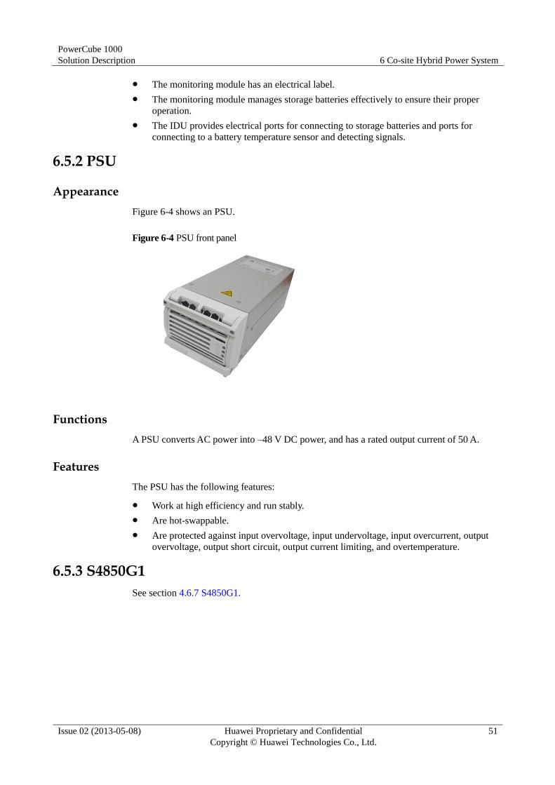
Appearance
Figure 6-4 shows an PSU.
Figure 6-4 PSU front panel
Functions
A PSU converts AC power into –48 V DC power, and has a rated output current of 50 A.
Features
The PSU has the following features:
Work at high efficiency and run stably.
Are hot-swappable.
Are protected against input overvoltage, input undervoltage, input overcurrent, output
overvoltage, output short circuit, output current limiting, and overtemperature.
6.5.3 S4850G1
See section 4.6.7 S4850G1.
PowerCube 1000
Solution Description 7 Indoor Sites with Upgraded TCUs
Issue 02 (2013-05-08) Huawei Proprietary and Confidential
Copyright © Huawei Technologies Co., Ltd.
52
7 Indoor Sites with Upgraded TCUs
7.1 Split-Type DC Variable Frequency Air Conditioner (Optional)
7.1.1 System Configuration
A split-type DC variable frequency air conditioner system consists of a split-type DC variable
frequency air conditioner (including an indoor unit and an outdoor unit) and an ECC500 or
air-condition controller (ACC). The ACC is used in the scenario with two split-type DC
variable frequency air conditioners.
An ECC500 applies to a 19-inch space, such as an open rack. If no 19-inch rack exists onsite,
Huawei will provide such a rack.
7.1.2 Network Diagrams
Figure 7-1 shows Network diagram for a split-type DC variable frequency air conditioner
system (with ECC500).

PowerCube 1000
Solution Description 7 Indoor Sites with Upgraded TCUs
Issue 02 (2013-05-08) Huawei Proprietary and Confidential
Copyright © Huawei Technologies Co., Ltd.
53
Figure 7-1 Network diagram for a split-type DC variable frequency air conditioner system(with
ECC500)
Figure 7-2 shows Network diagram for a split-type DC variable frequency air conditioner
system(without ECC500).
Figure 7-2 Network diagram for a split-type DC variable frequency air conditioner
system(without ECC500)
PowerCube 1000
Solution Description 7 Indoor Sites with Upgraded TCUs
Issue 02 (2013-05-08) Huawei Proprietary and Confidential
Copyright © Huawei Technologies Co., Ltd.
54
7.1.3 Model Description
Table 7-1 shows model description for a split-type DC variable frequency air conditioner.
Table 7-1 Model description for a split-type DC variable frequency air conditioner
Component Abbreviation Model
Split-type DC air conditioner N/A SP4D
Air-condition controller ACC ACC-01
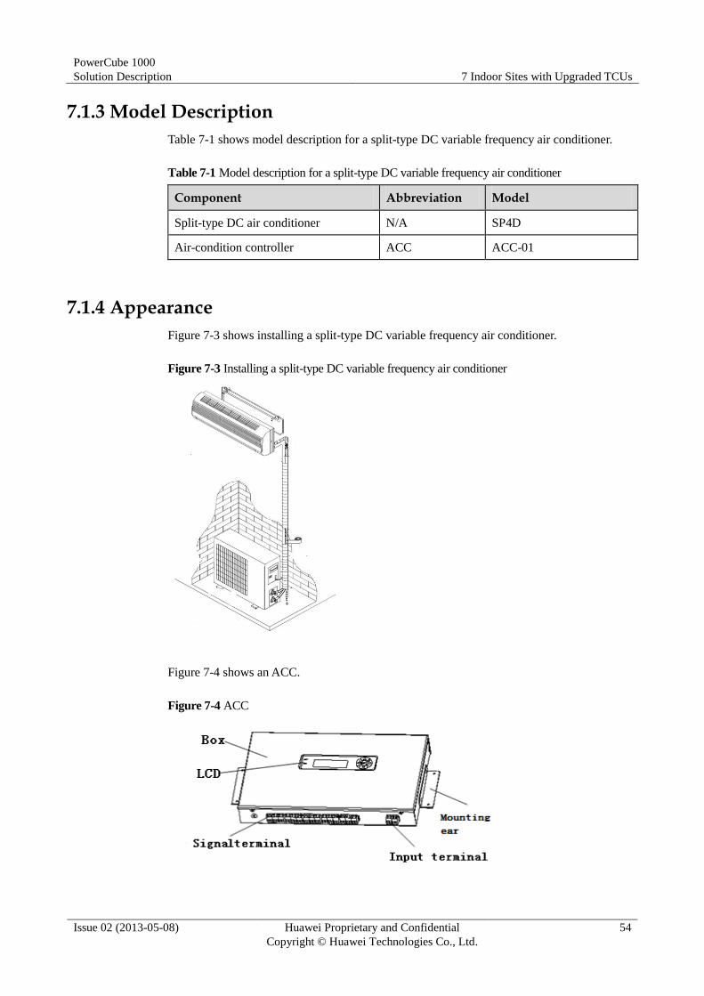
7.1.4 Appearance
Figure 7-3 shows installing a split-type DC variable frequency air conditioner.
Figure 7-3 Installing a split-type DC variable frequency air conditioner
Figure 7-4 shows an ACC.
Figure 7-4 ACC

PowerCube 1000
Solution Description 7 Indoor Sites with Upgraded TCUs
Issue 02 (2013-05-08) Huawei Proprietary and Confidential
Copyright © Huawei Technologies Co., Ltd.
55
7.1.5 Technical Specifications
Table 7-2 shows technical specifications for a split-type DC variable frequency air
conditioner.
Table 7-2 Technical specifications for a split-type DC variable frequency air conditioner
Item Specifications
Rated or operating voltage range 40–60 V DC
Total refrigeration capacity L35/L35: 4000 W
L35/L55: 2500 W
Refrigeration capacity range L35/L35: 2000–4000 W
L35/L55: 1500–2500 W
Maximum power L35/L35: 1200 W
L35/L55: 1400 W
Refrigerant R134a
Dimensions (H x W x D) Indoor unit: 990 mm x 210 mm x 320 mm
Outdoor unit: 760 mm x 290 mm x 550 mm
Weight Indoor unit: ≤ 35 kg
Outdoor unit: ≤ 50 kg
Table 7-3 shows the ACC technical specifications.
Table 7-3 ACC technical specifications
Item Specifications
Input Rated input voltage 48 V
Other features Protection Input low voltage protection and input
reverse-connection prevention
Operating temperature –20°C to +55°C
Humidity 5%–95% RH (non-condensing)
Dimensions (H x W x D) 43.6 mm x 316 mm x 186 mm
Heat dissipation mode Cooling as the ambient temperature drops
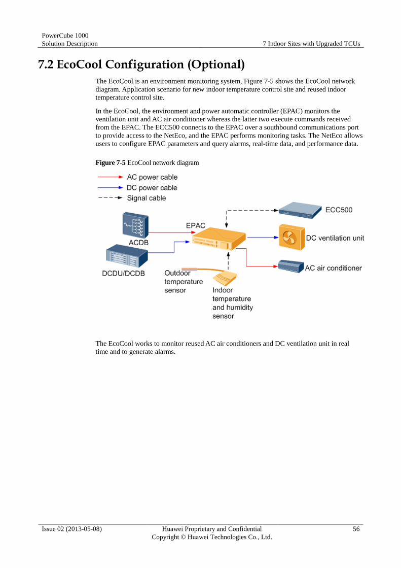
PowerCube 1000
Solution Description 7 Indoor Sites with Upgraded TCUs
Issue 02 (2013-05-08) Huawei Proprietary and Confidential
Copyright © Huawei Technologies Co., Ltd.
56
7.2 EcoCool Configuration (Optional)
The EcoCool is an environment monitoring system, Figure 7-5 shows the EcoCool network
diagram. Application scenario for new indoor temperature control site and reused indoor
temperature control site.
In the EcoCool, the environment and power automatic controller (EPAC) monitors the
ventilation unit and AC air conditioner whereas the latter two execute commands received
from the EPAC. The ECC500 connects to the EPAC over a southbound communications port
to provide access to the NetEco, and the EPAC performs monitoring tasks. The NetEco allows
users to configure EPAC parameters and query alarms, real-time data, and performance data.
Figure 7-5 EcoCool network diagram
The EcoCool works to monitor reused AC air conditioners and DC ventilation unit in real
time and to generate alarms.
PowerCube 1000
Solution Description 8 Monitoring
Issue 02 (2013-05-08) Huawei Proprietary and Confidential
Copyright © Huawei Technologies Co., Ltd.
57
8 Monitoring
8.1 New Monitoring Functions
Compared with the PowerCube 1000 with earlier versions, PowerCube 1000 V300R002C01
adds the following new functions:
Collects data about the electric energy production of the D.G. and mains, sends alarms
over short messages, and supports short message service (SMS) networking over the
900/1800 MHz frequency band.
Supports the input from third-party power supplies.
Manages various storage batteries covering ACBs, DCB-As, SCBs, FCBs, and flooded
batteries.
Copies parameter settings from a USB flash drive to the ECC during site deployment.
Manages the access of the SAU, CPMU01, PMU02B, and EPAC. The ECC500
communicates with the SAU, CPMU01, PMU02B, and EPAC over southbound
communications ports. The SAU, CPMU011, PMU02B, EPAC, NetEco, and ECC500 all
allow you to set parameters and the latest parameter setting prevails. The NetEco allows
you to set parameters for the SAU, CPMU01, PMU02B, and EPAC and to query alarms,
real-time data, and performance data.
Supports the access of DC meters.
The NetEco allows you to send reports to customers manually.
8.2 GMU-01A
Appearance
Figure 8-1 shows GMU-01A.
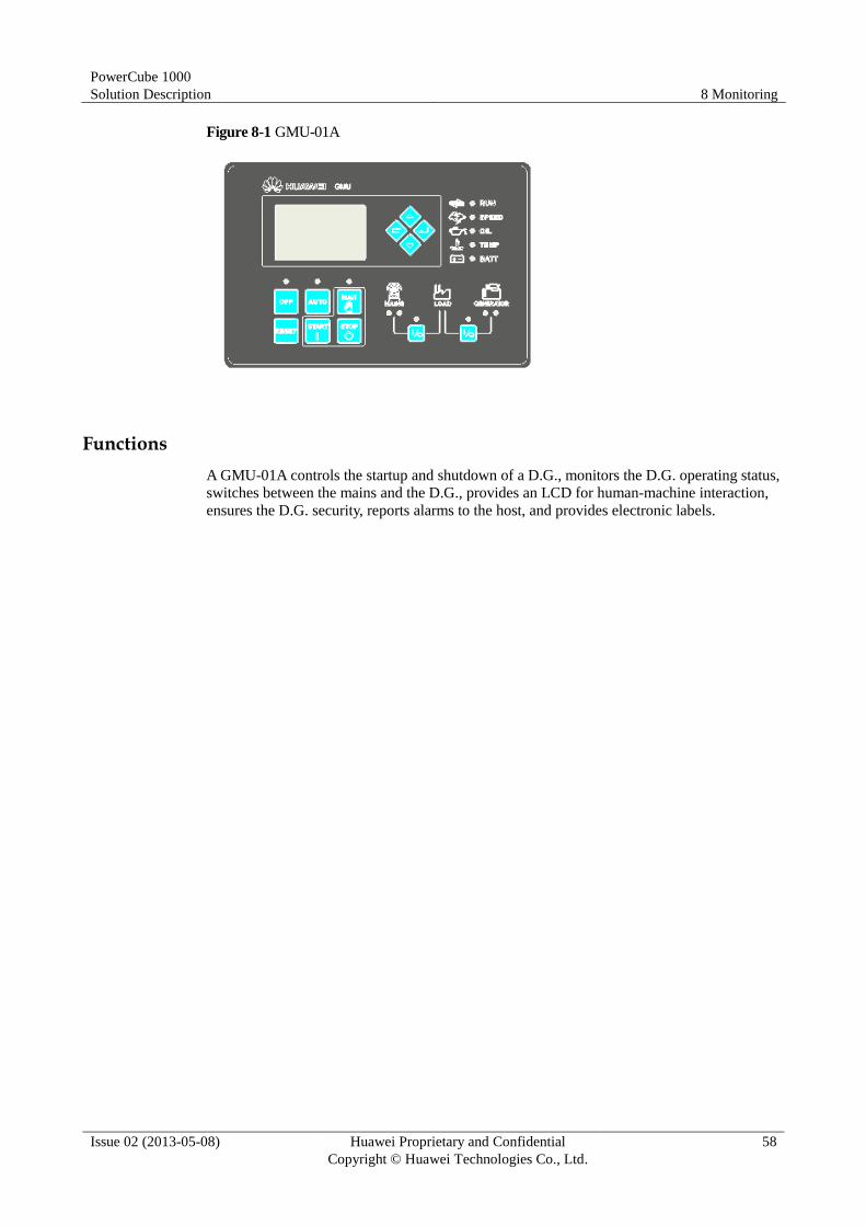
PowerCube 1000
Solution Description 8 Monitoring
Issue 02 (2013-05-08) Huawei Proprietary and Confidential
Copyright © Huawei Technologies Co., Ltd.
58
Figure 8-1 GMU-01A
Functions
A GMU-01A controls the startup and shutdown of a D.G., monitors the D.G. operating status,
switches between the mains and the D.G., provides an LCD for human-machine interaction,
ensures the D.G. security, reports alarms to the host, and provides electronic labels.
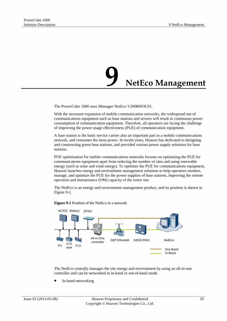
PowerCube 1000
Solution Description 9 NetEco Management
Issue 02 (2013-05-08) Huawei Proprietary and Confidential
Copyright © Huawei Technologies Co., Ltd.
59
9 NetEco Management
The PowerCube 1000 uses iManager NetEco V200R003C01.
With the incessant expansion of mobile communication networks, the widespread use of
communications equipment such as base stations and servers will result in continuous power
consumption of communication equipment. Therefore, all operators are facing the challenge
of improving the power usage effectiveness (PUE) of communication equipment.
A base station is the basic service carrier also an important part in a mobile communications
network, and consumes the most power. In recent years, Huawei has dedicated to designing
and constructing green base stations, and provided various power supply solutions for base
stations.
PUE optimization for mobile communications networks focuses on optimizing the PUE for
communications equipment apart from reducing the number of sites and using renewable
energy (such as solar and wind energy). To optimize the PUE for communications equipment,
Huawei launches energy and environment management solutions to help operators monitor,
manage, and optimize the PUE for the power supplies of base stations, improving the remote
operation and maintenance (OM) capacity of the entire site.
The NetEco is an energy and environment management product, and its position is shown in
Figure 9-1.
Figure 9-1 Position of the NetEco in a network
The NetEco centrally manages the site energy and environment by using an all-in-one
controller and can be networked in in-band or out-of-band mode.
In-band networking
GBTS/NodeB GBSC/RNCAll-in-One
controller
Out-Band
In-Band
D.G
tankPV
Battery AC/DC
D.G
NetEco
EPAC

PowerCube 1000
Solution Description 9 NetEco Management
Issue 02 (2013-05-08) Huawei Proprietary and Confidential
Copyright © Huawei Technologies Co., Ltd.
60
GSM sites (GBSS12.0 and later) or UMTS sites (RAN13.0 and later) send energy and
environment data to the NetEco through the OM channels provided only by Huawei
devices.
Out-of-band networking
Sites send energy and environment data to the NetEco over the IP, GPRS, SMS, or E1
network. The GPRS and SMS networks provide backup transmission channels for each
other if the network is unstable.
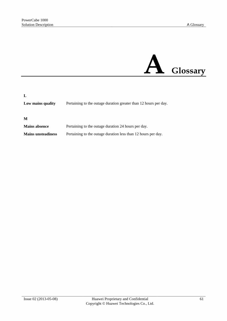
PowerCube 1000
Solution Description A Glossary
Issue 02 (2013-05-08) Huawei Proprietary and Confidential
Copyright © Huawei Technologies Co., Ltd.
61
A Glossary
L
Low mains quality Pertaining to the outage duration greater than 12 hours per day.
M
Mains absence Pertaining to the outage duration 24 hours per day.
Mains unsteadiness Pertaining to the outage duration less than 12 hours per day.

PowerCube 1000
Solution Description B Acronyms and Abbreviations
Issue 02 (2013-05-08) Huawei Proprietary and Confidential
Copyright © Huawei Technologies Co., Ltd.
62
B Acronyms and Abbreviations
A
AC alternating current
ACB advanced cycle battery
ACDU alternating current distribution unit
ATS automatic transfer switching
B
BC battery charger
BMU battery management unit
C
CAPEX Capital Expenditure
D
DC direct current
DCB-A deep cycle battery
DCDB direct current distribute box
DCDU direct current distribute unit
DOD depth of discharger
DTS direct current transfer switch
D.G. diesel generator
E
ECC energy control center
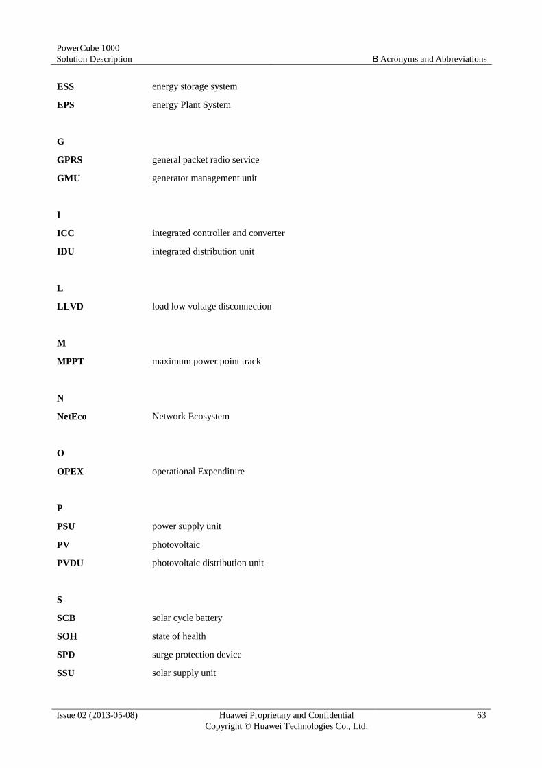
PowerCube 1000
Solution Description B Acronyms and Abbreviations
Issue 02 (2013-05-08) Huawei Proprietary and Confidential
Copyright © Huawei Technologies Co., Ltd.
63
ESS energy storage system
EPS energy Plant System
G
GPRS general packet radio service
GMU generator management unit
I
ICC integrated controller and converter
IDU integrated distribution unit
L
LLVD load low voltage disconnection
M
MPPT maximum power point track
N
NetEco Network Ecosystem
O
OPEX operational Expenditure
P
PSU power supply unit
PV photovoltaic
PVDU photovoltaic distribution unit
S
SCB solar cycle battery
SOH state of health
SPD surge protection device
SSU solar supply unit

PowerCube 1000
Solution Description B Acronyms and Abbreviations
Issue 02 (2013-05-08) Huawei Proprietary and Confidential
Copyright © Huawei Technologies Co., Ltd.
64
T
TCO Total Cost of Ownership
V
VRLA valve regulated lead acid