Power Transmission Solutions F O R M...Interference fits: Heat the hubs using an induction heater or...
4
F O R M KOP-GRID ® Tapered Grid Coupling - Type V Vertical Split Cover 17202E Revised November 2015 Power Transmission Solutions Regal Beloit America, Inc. 7120 New Buffington Road Florence, KY 41042 Application Engineering: 800 626 2093 www.RegalPTS.com INSTALLATION and ALIGNMENT INSTRUCTIONS These instructions apply to KOP-GRID ® type V tapered grid couplings. This sheet may be supplemented by Special Instructions supplied with the cou- pling for modifications and variations of these couplings. For dimensions, ratings, maximum bores, interference fits, and other technical information, please refer to Bulletin 1700. Always use caution when working on rotating equipment. Be sure to lock out the starting switch of prime mover so the equipment cannot be started until work is complete, checked, and personnel are safely away. Proper installation per this product instruction sheet must be observed. Failure to do so may void warranty and could result in injury to person or property. MAINTENANCE and LUBRICATION Lubricate the KOP-GRID ® coupling with grease only. Use KOP-FLEX ® KSG coupling grease or other grease meeting the minimum specifications shown. Do not use oil in KOP-GRID ® couplings. Coupling lubrication is critical. The use of proper and sufficient lubrication is part of a successful installation. Lubricants should be checked to ensure the proper level is maintained and that the lubricant is free of contaminates. In an average industrial application, the coupling should be checked for lubricant contamination and replenished with the proper volume every twelve months. Conditions such as very slow speed, reversing drives, high heat and severe environments may require more frequent lubrication. RECOMMENDED LUBRICANT KOP-FLEX ® KSG Coupling Grease This grease is specifically compounded for standard couplings to provide im- proved lubrication and resistance to centrifugal separation. When KSG grease is used, lubrication in- tervals may be extended, based upon operating experience. KSG coupling grease is available from Kop-Flex or authorized distributors of Kop-Flex power transmission products. OTHER GREASES Alternate lubricating greases should equal or exceed the specifications for KOP-FLEX ® KSG coupling grease (specification sheet 3532 is available upon request). Greases other than KSG should meet these minimum specifications: Grade: NLGI #1 Base oil Viscosity: Min: 3000 SSU at 100°F 160 SSU at 210°F Dropping Point, Min.: 190°F Four Ball Wear, ASTM D-2266: .500 mm Maximum Base Oil Content: 87% Minimum K36 Factor, ASTM D-4425: KSG: K36 = 8/25 =.33 Required: Rust and Oxidation Inhibitors E.P. Additives • Periodic inspections should be performed. Failure to perform proper maintenance can result in premature product failure and personal injury. • Read and follow all instructions carefully. • Disconnect and lock-out power before installation and maintenance. Working on or near energized equipment can result in severe injury or death. • Do not operate equipment without guards in place. Exposed equipment can result in severe injury or death.
Transcript of Power Transmission Solutions F O R M...Interference fits: Heat the hubs using an induction heater or...

F O R MKOP-GRID® Tapered GridCoupling - Type V Vertical Split Cover
17202ERevised
November 2015
Power Transmission SolutionsRegal Beloit America, Inc.7120 New Buffington Road
Florence, KY 41042Application Engineering: 800 626 2093
www.RegalPTS.com
INSTALLATION and ALIGNMENT INSTRUCTIONS
These instructions apply to KOP-GRID® type V tapered grid couplings.
This sheet may be supplemented by Special Instructions supplied with the cou-pling for modifications and variations of these couplings. For dimensions, ratings, maximum bores, interference fits, and other technical information, please refer to Bulletin 1700.
Always use caution when working on rotating equipment. Be sure to lock out the starting switch of prime mover so the equipment cannot be started until work is complete, checked, and personnel are safely away. Proper installation per this product instruction sheet must be observed. Failure to do so may void warranty and could result in injury to person or property.
MAINTENANCE and LUBRICATION
Lubricate the KOP-GRID® coupling with grease only. Use KOP-FLEX® KSG coupling grease or other grease meeting the minimum specifications shown.
Do not use oil in KOP-GRID® couplings.
Coupling lubrication is critical. The use of proper and sufficient lubrication is part of a successful installation.
Lubricants should be checked to ensure the proper level is maintained and that the lubricant is free of contaminates. In an average industrial application, the coupling should be checked for lubricant contamination and replenished with the proper volume every twelve months. Conditions such as very slow speed, reversing drives, high heat and severe environments may require more frequent lubrication.
RECOMMENDED LUBRICANT KOP-FLEX® KSG Coupling Grease
This grease is specifically compounded for standard couplings to provide im-proved lubrication and resistance to centrifugal separation. When KSG grease is used, lubrication in- tervals may be extended, based upon operating experience. KSG coupling grease is available from Kop-Flex or authorized distributors of Kop-Flex power transmission products.
OTHER GREASES
Alternate lubricating greases should equal or exceed the specifications for KOP-FLEX® KSG coupling grease (specification sheet 3532 is available upon request). Greases other than KSG should meet these minimum specifications:
Grade: NLGI #1Base oil Viscosity: Min: 3000 SSU at 100°F160 SSU at 210°F
Dropping Point, Min.: 190°F
Four Ball Wear, ASTM D-2266: .500 mm Maximum
Base Oil Content: 87% Minimum
K36 Factor, ASTM D-4425: KSG: K36 = 8/25 =.33
Required: Rust and Oxidation Inhibitors E.P. Additives
• Periodic inspections should be performed. Failure to perform proper maintenance can result in premature product failure and personal injury.
• Read and follow all instructions carefully.• Disconnect and lock-out power before installation and maintenance.
Working on or near energized equipment can result in severe injury or death.• Do not operate equipment without guards in place. Exposed equipment can
result in severe injury or death.
2 MCIM15128E • Form 17202E • Printed in USA
1. HUB INSTALLATION
Make sure the parts are on hand and are as ordered, check that the coupling bores and shaft diameters are correct. Clean all parts to remove protective com-pound. Lightly apply grease on seals and place a seal on each type V cover half. Install the half cover with seal and the gasket on the shafts, before mounting the hubs. If using an interference fit with a straight shaft connection, apply a suitable anti- galling compound to the shaft.
Do not use anti-galling compound on taper shafts. Install keys in shaft keyways with a snug side-to-side fit, and with a slight clearance top to bottom. For vertical shafts, seal the keyway to prevent grease leakage.
Clearance fits: Slide hub over shaft to the correct position, normally the shaft end is flush with the hub face.
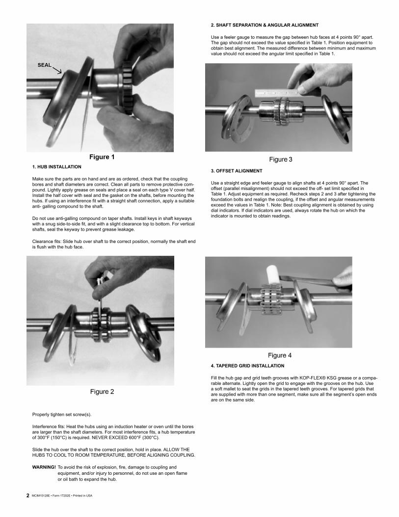
2. SHAFT SEPARATION & ANGULAR ALIGNMENT
Use a feeler gauge to measure the gap between hub faces at 4 points 90° apart. The gap should not exceed the value specified in Table 1. Position equipment to obtain best alignment. The measured difference between minimum and maximum value should not exceed the angular limit specified in Table 1.
3. OFFSET ALIGNMENT
Use a straight edge and feeler gauge to align shafts at 4 points 90° apart. The offset (parallel misalignment) should not exceed the off- set limit specified in Table 1. Adjust equipment as required. Recheck steps 2 and 3 after tightening the foundation bolts and realign the coupling, if the offset and angular measurements exceed the values in Table 1. Note: Best coupling alignment is obtained by using dial indicators. If dial indicators are used, always rotate the hub on which the indicator is mounted to obtain readings.
4. TAPERED GRID INSTALLATION
Fill the hub gap and grid teeth grooves with KOP-FLEX® KSG grease or a compa-rable alternate. Lightly open the grid to engage with the grooves on the hub. Use a soft mallet to seat the grids in the tapered teeth grooves. For tapered grids that are supplied with more than one segment, make sure all the segment’s open ends are on the same side.
Properly tighten set screw(s).
Interference fits: Heat the hubs using an induction heater or oven until the bores are larger than the shaft diameters. For most interference fits, a hub temperature of 300°F (150°C) is required. NEVER EXCEED 600°F (300°C).
Slide the hub over the shaft to the correct position, hold in place. ALLOW THE HUBS TO COOL TO ROOM TEMPERATURE, BEFORE ALIGNING COUPLING.
WARNING! To avoid the risk of explosion, fire, damage to coupling and equipment, and/or injury to personnel, do not use an open flame or oil bath to expand the hub.

MCIM15128E • Form 17202E • Printed in USA 3
GRID REMOVAL:
Remove the coupling cover assembly. Insert a rod or screw driver into the open end loop of the tapered grid. Use the teeth on the coupling hub as a support to gradually and gently pry off the grid, proceeding alternately from side to side.
5. COVER INSTALLATION & LUBRICATION
Pack the grid with additional KSG grease or the equivalent and wipe off the excess flush with the top of the grid. For ease of assembly, remove the lube plugs. Slide the half cover on the hub to line up with the other half cover and position the gasket between the two half covers. Install the cover fasteners and tighten to the cover bolt torque value specified in Table 1. For lubrication, fill with KOP-FLEX® KSG grease or specified alternate, until the grease starts seeping out from the other lube hole. Re-install the two lube plugs in the covers and tighten securely. NOTE: DO NOT OPERATE COUPLING WITHOUT THE LUBE PLUGS.
TABLE 1Installation and alignment values
SizeMaximum recommended
misaligment limits Gap(In.)
Cover Bolt Torque (Lb.-In.)
AllowableMaximum Speed
(RPM)Lube/GreaseWeight (Lb.)
Offset (In.) Angular (In.)1020 0.006 0.003 0.125 100 6,000 0.071030 0.006 0.003 0.015 100 6,000 0.071040 0.006 0.003 0.125 100 6,000 0.111050 0.008 0.004 0.125 200 6,000 0.111060 0.008 0.005 0.125 200 6,000 0.201070 0.008 0.005 0.125 200 5,500 0.241080 0.008 0.006 0.125 200 4,750 0.371090 0.008 0.007 0.125 200 4,000 0.551100 0.010 0.008 0.188 260 3,250 0.951110 0.010 0.009 0.188 260 3,000 1.121120 0.011 0.010 0.250 650 2,700 1.611130 0.011 0.012 0.250 650 2,400 2.001140 0.011 0.013 0.250 650 2,200 2.50

Kop-Flex and KOP-GRID are trademarks of Regal Beloit Corporation or one of its affiliated companies. ©2015 Regal Beloit Corporation, All Rights Reserved. MCIM15128E • Form 17202E • Printed in USA
Notes: