
POWER GRADER SAFETY & OPERATING INSTRUCTIONS
32
Read and understand this manual and all instructions before operating the DR POWER GRADER. ` Original Language DR ® POWER GRADER SAFETY & OPERATING INSTRUCTIONS Serial No. Order No. DR Power Equipment Toll-free phone: 1-800-DR-OWNER (376-9637) Fax: 1-802-877-1213 Website: www.DRpower.com
Transcript of POWER GRADER SAFETY & OPERATING INSTRUCTIONS

Read and understand this manual and all instructions before operating the DR POWER GRADER.
`
Original Language
DR® POWER GRADER
SAFETY & OPERATING INSTRUCTIONS
Serial No.
Order No.
DR Power Equipment Toll-free phone: 1-800-DR-OWNER (376-9637) Fax: 1-802-877-1213 Website: www.DRpower.com

2 DR® POWER GRADER
This indicates a hazardous situation which, if not avoided, could result in death or serious injury.
Table of Contents Chapter 1: General Safety Rules ............................................................................................................................................................ 3
Chapter 2: Setting Up the DR POWER GRADER .................................................................................................................................. 6
Chapter 3: Operating The DR POWER GRADER ................................................................................................................................. 17
Chapter 4: Maintaining The DR POWER GRADER .............................................................................................................................. 21
Chapter 5: Troubleshooting .................................................................................................................................................................. 23
Chapter 6: Parts Lists, Schematic Diagrams and Warranty ................................................................................................................. 24
Conventions used in this manual
Serial Number and Order Number
A Serial Number is used to identify your machine and is located on the Serial Number Label on your machine (Figure 1). An Order Number is used to check and maintain your order history and is located on the upper left portion of your packing slip. For your convenience and easy reference, enter the Serial Number and Order Number in the space provided on the front cover of this manual.
Additional Information and Potential Changes
DR Power Equipment reserves the right to discontinue, change, and improve its products at any time without notice or obligation to the purchaser. The descriptions and specifications contained in this manual were in effect at printing. Equipment described within this manual may be optional. Some illustrations may not be applicable to your machine.
Serial Number Label
Figure 1
Tow Bar
This information is important in the proper use of your machine. Failure to follow this instruction could result in damage to your machine or property.
This indicates a hazardous situation which, if not avoided, could result in minor or moderate injury.

CONTACT US AT www.DRpower.com 3
Read this safety & operating Instructions manual before you use the DR POWER GRADER. Become familiar with the operation and service recommendations to ensure the best performance from your machine. If you have any questions or need assistance, please contact us at www.DRpower.com or call toll-free 1-800-DR-OWNER (376-9637) and one of our Technical Support Representatives will be happy to help you.
Always take the following precautions when operating this grader: Always wear protective goggles or safety glasses with side shields while grading to protect your eyes from possible thrown bits
of dirt or gravel. Wear shoes with non-slip treads when using your DR Power Grader. If you have safety shoes, we recommend wearing them.
Do not use the grader while barefoot or wearing open sandals. Wear a helmet when operating an ATV.
Chapter 1: General Safety Rules
Labels Your DR POWER GRADER carries prominent labels as reminders for its proper and safe use. Shown below are copies of all the Safety and Information labels that appear on the equipment. Take a moment to study them and make a note of their location on your POWER GRADER as you set up and before you operate the unit. Replace damaged or missing safety and information labels immediately.
Protecting Yourself and Those Around You
Safety for Children and Pets
#37281 #37284
#38913
Tragic accidents can occur if the operator is not alert to the presence of children and pets. Children and pets are often attracted to the grading activity. Never assume that children or pets will remain where you last saw them. Keep children out of the grading area and under the watchful care of a responsible adult. Be alert, stop and turn the tow vehicle off if children or pets enter the work area. Never allow children to operate the DR Power Grader. Never allow children or pets to ride on the tow vehicle or the DR Power Grader.
4 DR® POWER GRADER
You must operate the Power Grader safely. Unsafe operation can create a number of hazards for you. Always take the following precautions when using this Grader: Read, understand, and follow all instructions in this manual. Be thoroughly familiar with the controls and the proper use of
your Grader before using. Thoroughly inspect the area where your Grader will be used, and remove all large stones, sticks, wire, pet supplies, lawn toys,
and any other foreign objects that you could run over. Also, note the location of stumps and other possible hazards that you should avoid during operation.
Watch for traffic when operating in or near roadways. Pay extra attention when operating near public roadways. When operating in a roadway, we suggest that you put out obstructions (marker cones or pails) to divert any traffic away from
your work area. Be aware of your surroundings when operating the DR Power Grader, e.g. ditches, culverts, drop-offs, and hills. Never allow people who are unfamiliar with these instructions to use the DR Power Grader. To be safe, do not operate the grader near small children or pets, and never allow children to operate the Power Grader. Stop
the grading action when another person or pet approaches. Do not allow people to ride on the Grader. If you have to stop to remove any debris from the Grader, always shut off the tow vehicle’s engine and set the parking brake. Do not, under any conditions, remove, bend, cut, fit, weld, or otherwise alter standard parts on the DR Power Grader.
Modifications to your machine could cause personal injuries and will void your warranty. While using the DR Power Grader, don't hurry or take things for granted. Do not operate the Grader when under the influence of alcohol or medication. Use the DR Power Grader only in daylight or good artificial light.
The DR Power Grader must be operated safely to prevent or minimize the risk of minor or moderate injury. Unsafe operation can create a number of hazards for you. Always take the following precautions when operating this Power Grader: Keep in mind that the operator or user is responsible for accidents or hazards occurring to other people, their property, and
themselves. Do not use the DR Power Grader to drag, tow, or carry items. Never operate the DR Power Grader with a truck (2wd or 4wd); doing so will void the DR Power Grader warranty. Never leave the DR Power Grader unattended. If you leave the area, shut off the tow vehicle, and remove the key. Keep all nuts and bolts tight and keep the equipment and attachments in good operating condition. Use only manufacturer-recommended replacement parts. Do not use the DR Power Grader in a manner not in accordance with these instructions.
Operating the DR POWER GRADER Safely
Safety with Electric-Powered Machines
Never overlook the hazards of electricity. Always follow these precautions: Never attempt to open the motor assembly. Never attempt any electrical repairs yourself. If in doubt, consult a qualified
electrician, contact us at www.DRpower.com or call 1-800-dr-owner (376-9637) for help or information. Never tamper with safety devices. Check their proper operation regularly.

CONTACT US AT www.DRpower.com 5
California Proposition 65: This product contains or emits chemicals known to the State of California to cause cancer, birth defects, and other
reproductive harm.
Use only the 12-volt, lead-acid, rechargeable battery and the 12-volt battery charger that shipped with your grader, or the DR Power Equipment replacement. Using the wrong type of battery or a charger, other than the DR Power Equipment charger, could cause a fire or explosion resulting in serious injury.
Never lift or carry the battery by the wires or connectors. This can damage the battery and possibly cause a fire resulting in serious injury. Lift and carry the battery by the case only.
Only adults should handle the battery. The battery is heavy and contains sulfuric acid (electrolyte). Dropping the battery could result in serious injury. Have a firm grip and use caution when removing or changing the battery.
Batteries contain sulfuric acid. To prevent burns, avoid contact with skin, eyes, and clothing. To prevent fire or explosion keep sparks and open flames away from the battery.
Exercise care in handling the battery in order not to short-circuit it with conducting materials such as rings, bracelets, and keys. When short-circuited, the battery or conductor may overheat and cause burns.
Please dispose of used batteries responsibly, according to your local hazardous materials regulations. Never throw away used batteries in your household trash. Bring them to a recycling center or household hazardous waste depot for proper disposal. Please refer to “recycling a used battery”, on page 22, for more information.
Handling the Battery Safely
Safely Charging the Battery
California Proposition 65
A Note to All Users No list of warnings and cautions can be all-inclusive. If situations occur that are not covered by this manual, the operator must apply common sense and operate this DR POWER GRADER in a safe manner. Contact us at www.DRpower.com or call 1-800-DR-OWNER (376-9637) for assistance.
Never allow the battery to completely discharge; charge the battery before this happens. Charge the battery before storing your DR Power Grader. Do not leave the battery discharged, as this can ruin it.
Examine the charger and the connectors for excessive wear or damage each time you charge the battery. If you determine there is a problem, do not use the charger or the battery until you have replaced the worn or damaged part.
Never allow children to charge the battery. The electricity involved in charging the battery could injure a child. Never charge the battery in the rain or in wet locations.
6 DR® POWER GRADER
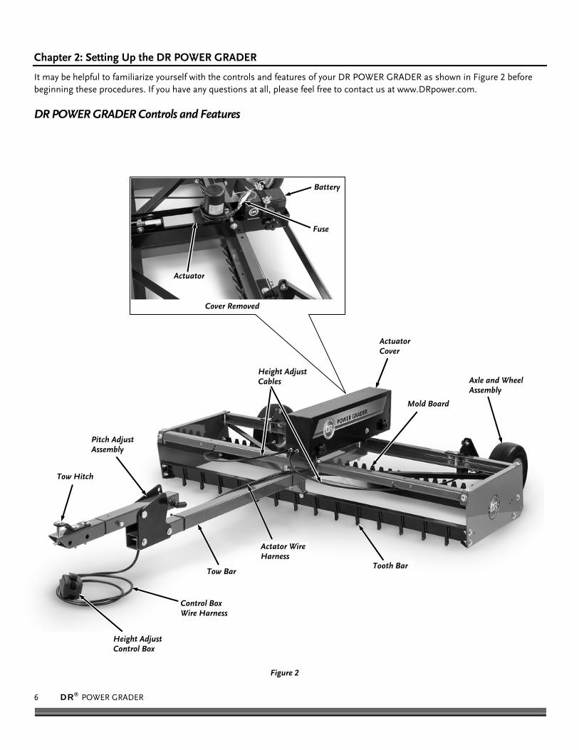
Figure 2
Height Adjust Cables
Mold Board
Tooth Bar
Axle and Wheel Assembly
Actuator
Battery
Fuse
Cover Removed
Height Adjust Control Box
Actuator Cover
Actator Wire Harness
Control Box Wire Harness
Tow Bar
Pitch Adjust Assembly
Tow Hitch
Chapter 2: Setting Up the DR POWER GRADER
It may be helpful to familiarize yourself with the controls and features of your DR POWER GRADER as shown in Figure 2 before beginning these procedures. If you have any questions at all, please feel free to contact us at www.DRpower.com.
DR POWER GRADER Controls and Features

CONTACT US AT www.DRpower.com 7
Figure 3
2
1
3
5
4
6
7 8
Specifications
48" Model 60" Model
Teeth 12 ea. 14 ea.
Material 90/10 Tungsten/Carbide tipped 4142 Hardened Alloy Steel
90/10 Tungsten/Carbide tipped 4142 Hardened Alloy Steel
Distance Between Teeth 4" 4"
Length 3-5/8" 3-5/8"
Mold Board Cold rolled Steel, .25" Thick Cold rolled Steel, .25" Thick
Reversible Grading or grooming blade types Grading or grooming blade types
Adjustable Angle 50 degrees for aggressive cutting 90 degrees for light dragging/mixing 105 degrees for light material/grooming)
50 degrees for aggressive cutting 90 degrees for light dragging/mixing 105 degrees for light material/grooming)
Frame 12 gauge side plates, 10 gauge rails, 2" square tow bar
12 gauge side plates, 10 gauge rails, 2" square tow bar
Actuator Electric actuator w/ 4" Stroke Electric actuator w/ 4" Stroke
Teeth Positions Actuator raises and lowers Teeth from 4.5” above surface to 9/16” below
Actuator raises and lowers Teeth from 4.5” above surface to 9/16” below
Wheels 11" diameter x 4" wide x 5" rim 11" diameter x 4" wide x 5" rim
Hitch Dual hitch system allows tow vehicle to use pin or ball hitches
Dual hitch system allows tow vehicle to use pin or ball hitches
Weight capacity (blocks) 80lbs (2 standard 16"x8"x8" cinder blocks) 80lbs (2 standard 16"x8"x8" cinder blocks)
Remote Control Rocker switch tethered control – operator can adjust height of teeth from tow vehicle
Rocker switch tethered control – operator can adjust height of teeth from tow vehicle
Battery 12 volt 9Ah Battery with Charger 12 volt 9Ah Battery with Charger
Drag Screen Optional drag screen Optional drag screen
Minimum Tow Vehicle HP Tow vehicle must be minimum of 14hp, 400 lb tractor or 350cc 4WD ATV- Max 24" hitch height
Tow vehicle must be minimum of 19hp, 500 lb tractor, or 500cc 4WD ATV
Dimensions 76" L X 49"W X 17" H 88" L X 60" W X 17" H
Weight 168LBS 175LBS
Main Parts (Figure 3 and Table below) Item# Description Qty
1 ........... Tow Bar .........................................................1 2 ........... Pitch Bar ........................................................1 3 ........... Tongue Bar ....................................................1 4 ........... Ball Hitch .......................................................1 5 ........... Axle ................................................................1 6 ........... Wheel Assembly ............................................2 7 ........... Actuator Assembly ........................................1 8 ........... Parts Box (see Figure 4) ................................1 9 ........... Battery Charger .............................................1
Use Figure 3 and the list above to check the parts you received in the package. If you have any questions, please contact us at www.DRpower.com or call 1-800-DR-OWNER (376-9637) for assistance.
8 DR® POWER GRADER
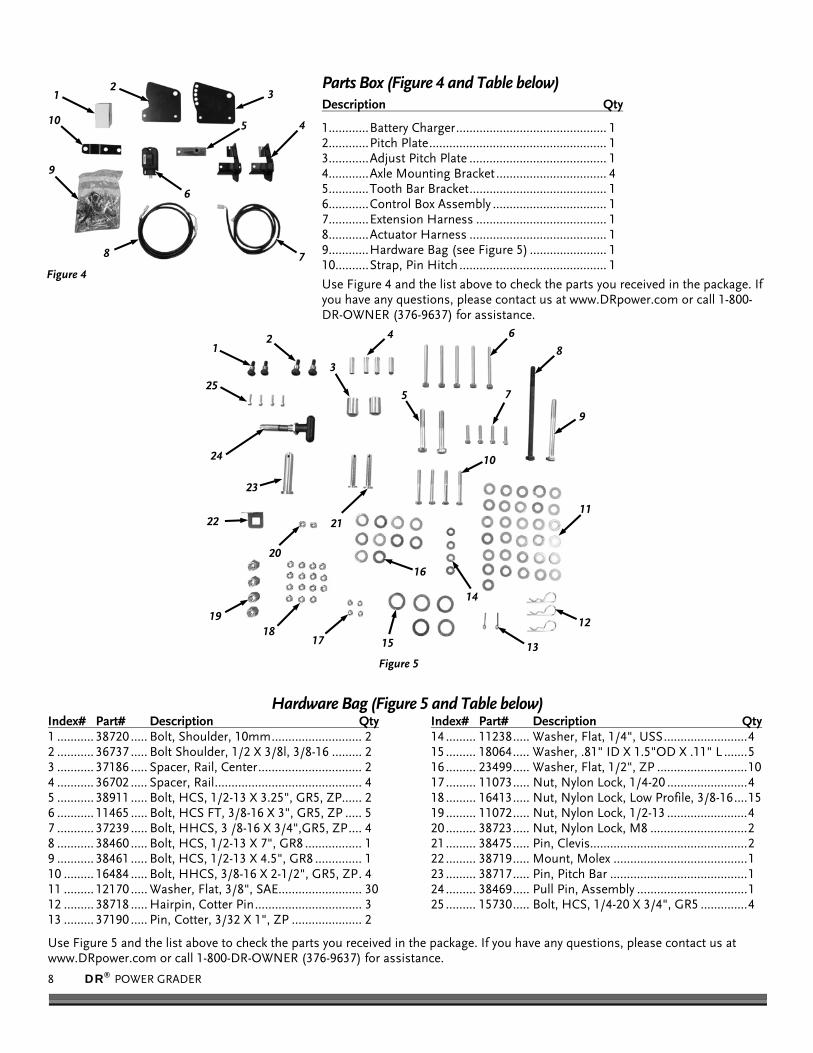
Figure 4
2 1
4
6
5
7 8
3
9
10
Parts Box (Figure 4 and Table below) Description Qty
1............ Battery Charger ............................................. 1 2............ Pitch Plate ..................................................... 1 3............ Adjust Pitch Plate ......................................... 1 4............ Axle Mounting Bracket ................................. 4 5............ Tooth Bar Bracket ......................................... 1 6............ Control Box Assembly .................................. 1 7............ Extension Harness ....................................... 1 8............ Actuator Harness ......................................... 1 9............ Hardware Bag (see Figure 5) ....................... 1 10 .......... Strap, Pin Hitch ............................................ 1
Use Figure 4 and the list above to check the parts you received in the package. If you have any questions, please contact us at www.DRpower.com or call 1-800-DR-OWNER (376-9637) for assistance.
Hardware Bag (Figure 5 and Table below)Index# Part# Description Qty 1 ........... 38720 ..... Bolt, Shoulder, 10mm ........................... 2 2 ........... 36737 ..... Bolt Shoulder, 1/2 X 3/8l, 3/8-16 ......... 2 3 ........... 37186 ..... Spacer, Rail, Center ............................... 2 4 ........... 36702 ..... Spacer, Rail ............................................ 4 5 ........... 38911 ..... Bolt, HCS, 1/2-13 X 3.25", GR5, ZP ...... 2 6 ........... 11465 ..... Bolt, HCS FT, 3/8-16 X 3", GR5, ZP ..... 5 7 ........... 37239 ..... Bolt, HHCS, 3 /8-16 X 3/4",GR5, ZP .... 4 8 ........... 38460 ..... Bolt, HCS, 1/2-13 X 7", GR8 ................. 1 9 ........... 38461 ..... Bolt, HCS, 1/2-13 X 4.5", GR8 .............. 1 10 ......... 16484 ..... Bolt, HHCS, 3/8-16 X 2-1/2", GR5, ZP . 4 11 ......... 12170 ..... Washer, Flat, 3/8", SAE......................... 30 12 ......... 38718 ..... Hairpin, Cotter Pin ................................ 3 13 ......... 37190 ..... Pin, Cotter, 3/32 X 1", ZP ..................... 2
Index# Part# Description Qty 14 ......... 11238 ..... Washer, Flat, 1/4", USS ......................... 4 15 ......... 18064 ..... Washer, .81" ID X 1.5"OD X .11" L ....... 5 16 ......... 23499 ..... Washer, Flat, 1/2", ZP ........................... 10 17 ......... 11073 ..... Nut, Nylon Lock, 1/4-20 ........................ 4 18 ......... 16413 ..... Nut, Nylon Lock, Low Profile, 3/8-16 .... 15 19 ......... 11072 ..... Nut, Nylon Lock, 1/2-13 ........................ 4 20 ......... 38723 ..... Nut, Nylon Lock, M8 ............................. 2 21 ......... 38475 ..... Pin, Clevis............................................... 2 22 ......... 38719 ..... Mount, Molex ........................................ 1 23 ......... 38717 ..... Pin, Pitch Bar ......................................... 1 24 ......... 38469 ..... Pull Pin, Assembly ................................. 1 25 ......... 15730 ..... Bolt, HCS, 1/4-20 X 3/4", GR5 .............. 4
Use Figure 5 and the list above to check the parts you received in the package. If you have any questions, please contact us at www.DRpower.com or call 1-800-DR-OWNER (376-9637) for assistance.
Figure 5
1 2
3
4
5
8
9
10
11
14
15
12
13
7
17
6
18 19
21
20
22
23
16
24
25

CONTACT US AT www.DRpower.com 9
Tools Needed Two 9/16" Wrenches Two 3/4" Wrenches 7/8" Wrench 1/4" Allen Wrench Needle Nose Pliers 7/16" Wrench Ratchet, Extension and 7/16" Socket Two 1/2" Wrenches Wire Cutters 13mm Wrench 5mm Allen Wrench
Assembly
1. Position the Power Grader Frame on a clean flat surface with the Weight Box Straps on top (Figure 6).
Note: The Weight Box Straps are secured at the ends but not at the center of the machine. You may need to loosen the hardware at the ends before performing the next step.
2. Rotate the Weight Box Straps to align with the mounting holes in the front Crossmember. Secure each Strap with a 3/8-16 X 2-1/2" Bolt, 3/8" Flat Washer, Rail Spacer (inside Crossmember), 3/8" Flat Washer and a Locknut using two 9/16" Wrenches. Tighten hardware on the other end of the Weight Box Straps.
3. Position the Frame Assembly, with the front facing up, to gain access to the Tooth Bar area (Figure 7).
4. Support the Tooth Bar as you remove the four Bolts, Flat Washers and Locknuts that are securing the Tooth Bar using two 9/16" Wrenches.
5. Turn the Tooth Bar around and flip end to end so the teeth are facing forward. Secure the Tooth Bar with the Bolts, Flat Washers and Locknuts but do not fully tighten at this time.
Tooth Bar
Bolts, Washers and Locknuts
Figure 7
Weight Box Straps
Figure 6
Rail Spacers
Bolt, Washers and Locknut
10 DR® POWER GRADER
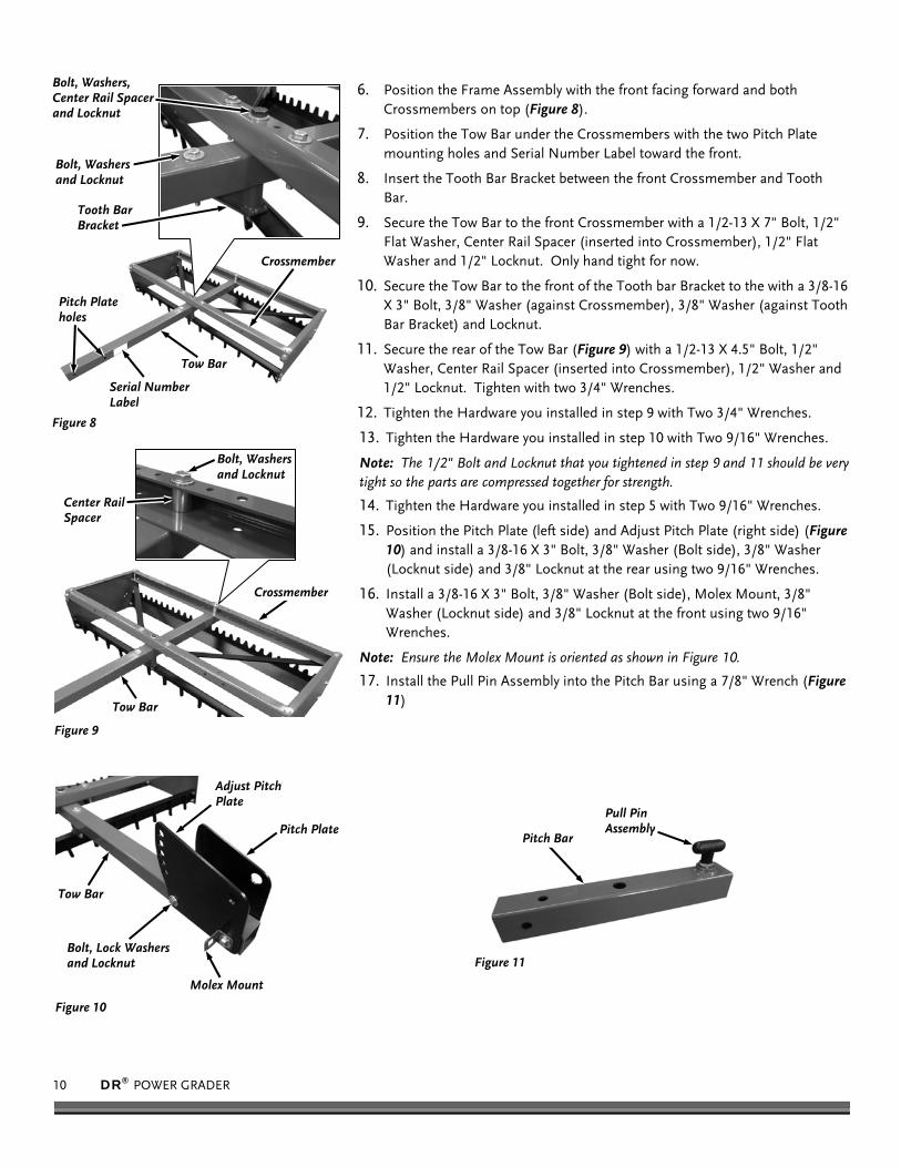
6. Position the Frame Assembly with the front facing forward and both Crossmembers on top (Figure 8).
7. Position the Tow Bar under the Crossmembers with the two Pitch Plate mounting holes and Serial Number Label toward the front.
8. Insert the Tooth Bar Bracket between the front Crossmember and Tooth Bar.
9. Secure the Tow Bar to the front Crossmember with a 1/2-13 X 7" Bolt, 1/2" Flat Washer, Center Rail Spacer (inserted into Crossmember), 1/2" Flat Washer and 1/2" Locknut. Only hand tight for now.
10. Secure the Tow Bar to the front of the Tooth bar Bracket to the with a 3/8-16 X 3" Bolt, 3/8" Washer (against Crossmember), 3/8" Washer (against Tooth Bar Bracket) and Locknut.
11. Secure the rear of the Tow Bar (Figure 9) with a 1/2-13 X 4.5" Bolt, 1/2" Washer, Center Rail Spacer (inserted into Crossmember), 1/2" Washer and 1/2" Locknut. Tighten with two 3/4" Wrenches.
12. Tighten the Hardware you installed in step 9 with Two 3/4" Wrenches.
13. Tighten the Hardware you installed in step 10 with Two 9/16" Wrenches.
Note: The 1/2" Bolt and Locknut that you tightened in step 9 and 11 should be very tight so the parts are compressed together for strength.
14. Tighten the Hardware you installed in step 5 with Two 9/16" Wrenches.
15. Position the Pitch Plate (left side) and Adjust Pitch Plate (right side) (Figure 10) and install a 3/8-16 X 3" Bolt, 3/8" Washer (Bolt side), 3/8" Washer (Locknut side) and 3/8" Locknut at the rear using two 9/16" Wrenches.
16. Install a 3/8-16 X 3" Bolt, 3/8" Washer (Bolt side), Molex Mount, 3/8" Washer (Locknut side) and 3/8" Locknut at the front using two 9/16" Wrenches.
Note: Ensure the Molex Mount is oriented as shown in Figure 10.
17. Install the Pull Pin Assembly into the Pitch Bar using a 7/8" Wrench (Figure 11)
Crossmember
Figure 8
Tow Bar
Pitch Plate holes
Bolt, Washers and Locknut
Bolt, Washers, Center Rail Spacer and Locknut
Tooth Bar Bracket
Serial Number Label
Pitch Bar
Figure 11
Pull Pin Assembly Pitch Plate
Figure 10
Adjust Pitch Plate
Molex Mount
Tow Bar
Bolt, Lock Washers and Locknut
Crossmember
Figure 9
Tow Bar
Bolt, Washers and Locknut
Center Rail Spacer

CONTACT US AT www.DRpower.com 11
18. Position the Pitch Bar between the Pitch Plates and secure with the Pitch Bar Pin, .81" ID X 1.5"OD X .11" Washer and Hair Pin Cotter Pin (Figure 12).
Note: The Pull Pin Assembly will need to be pulled out to position the Pitch Bar between the Pitch Plates.
19. Insert the Tongue Bar into the Pitch Bar and secure with the Clevis Pin, 1/2" Washer and Hairpin Cotter Pin (Figure 13).
20. PIN HITCH INSTALL:
Note: Position the Hitch Clevis Pin into the Pin Hitch Strap and Tongue Bar to align parts for the next step.
a) Install the Pin Hitch Strap onto the Tongue Bar with two 3/8-16 X 3" Bolts, 3/8" Washers (Bolt Side), 3/8" Washers (Locknut side) and 3/8" Locknuts using two 9/16" Wrenches.
b) Install a 1/2" Washer and Hairpin Cotter Pin to secure the Hitch Clevis Pin.
BALL HITCH INSTALL:
a) Install the Ball Hitch onto the Tongue Bar with two 1/2-13 X 3.25" Bolts, 1/2" Washers (Bolt Side), 1/2" Washers (Locknut side) and 1/2" Locknuts using two 3/4" Wrenches (Figure 14).
b) Install a 1/2" Washer and Hairpin Cotter Pin to secure the Hitch Clevis Pin.
21. Secure the top of a Axle Mounting Bracket onto the rear Crossmember with a 3/8-16 X 2-1/2" Bolt, 3/8" Washer (Bolt side), Rail Spacer (inside Crossmember) 3/8" Washer (locknut side) and 3/8" Locknut using two 9/16" Wrenches (Figure 15).
22. Secure the rear of the Axle Mounting Bracket to the Crossmember with 3/8-16 X 3/4" Bolts, 3/8" Washers (Bolt side), 3/8" Washers (locknut side) and 3/8" Locknut using two 9/16" Wrenches.
23. Install the second Axle Mounting Bracket as described in the last step.
Pitch Bar Pin
Figure 12
Pull Pin Assembly
Washer and Hitch Clip
Pitch Bar
Axle Bracket
Figure 15
Bolt, Washers, Rail Spacer and Locknut
Bolt, Washers, and Locknut
Ball Hitch
Figure 14
Bolt, Washers and Locknut
Clevis Pin
Figure 13
Tongue Bar
Washer and Hitch Clip
Pin Hitch Strap
Washer and Hitch Clip
Clevis Pin

12 DR® POWER GRADER
24. Install the Axle to both Axle Brackets with a 1/2 X 3/8L, 3/8-16 Shoulder Bolt, 3/8" Washer (Locknut Side) and 3/8" Locknut using a 4mm Allen Wrench on the Bolt and 9/16" Wrench on the Locknut (Figure 16).
Note: Ensure that the Axle Weldment and Hardware is oriented as shown with the Bolt and Axle Arm on the right side of the Bracket.
25. Install a .81" ID X 1.5"OD X .11" L Washer onto one end of the Axle, followed by a Wheel Assembly (Grease Fitting facing out) (Figure 17).
26. Secure the Wheel Assembly with another .81" ID X 1.5"OD X .11" L Washer and 3/32 X 1" Cotter Pin. Use Needle Nose Pliers to bend the Cotter pin ends over.
27. Install a Wheel Assembly on the other end of the Axle as described above.
28. Loosen the Hand Knobs securing the Actuator Cover and remove the Cover.
29. Remove the Wing Nuts and lift the Battery Strap and Battery out of the Actuator Assembly (Figure 19).
30. Position the Actuator Assembly onto the Frame Crossmembers with the Cables towards the front (Figure 20).
31. Position the large holes in the Actuator Assembly over the large Crossmember Bolts. Align the four mounting holes of the Actuator Assembly.
Note: Insert the Bolts from the bottom (Crossmember side) in the next step.
32. Secure the Actuator Assembly to the Crossmembers with four 1/4-20 X 3/4" Bolts, 1/4" Washers (one on Bolt side and one on Locknut side) and 1/4" Locknuts using a 7/16" Wrench and a 7/16" Socket with Ratchet and Extension.
33. Reinstall the Battery with the Battery Strap and Wing Nuts.
Wing Nuts
Figure 19
Battery Strap
Battery
Bolt, Washer and Locknut
Figure 20
Bolt, Washer and Locknut
Crossmembers
Actuator Cover
Figure 18 Hand Knobs
Wheel Assembly
Figure 17
Washer and Cotter Pin
Axle
Figure 16
Axle Brackets
Axle Bracket
Washer and Locknut
Shoulder Bolt

CONTACT US AT www.DRpower.com 13
34. Route the Height Adjust Cables back under the Crossmembers towards the rear of the Frame. Ensure the Cables are on top of the Tooth Bar and Mold Board (Figure 21).
35. Pull the Rubber Boot off the threads of the both Height Adjust Cables and unscrew the outer Nut off the threads (Figure 22).
36. Ensure the inner Nut on each Cable is screwed onto the threads as far as it will go.
37. Slide the Cables into the slots of the Axle Brackets and pull the threads through the hole (Figure 23).
38. Install the outer Nuts and screw all the way on. Hold the inner Nut as you tighten the outer nut using two 1/2" Wrenches on both Cables (Figure 24).
39. Slide the Rubber Boots onto the threads.
40. Insert the 10mm Shoulder Bolts through the Cable Eyelets and into the hole of the Axle Weldment (Figure 25).
41. Secure the Bolts with 3/8" Washers and M8 Locknuts using a 5mm Allen Wrench for the Locknut and a 13mm Wrench.
42. Use the holes through the front Crossmember to secure the Height Adjust Cables with Cable Ties (Figure 26).
Height Adjust Cable
Figure 26
Cable Tie
Shoulder Bolt, Washer and Locknut
Figure 25
Rubber Boot
Figure 24
Jam Nut
Cable
Figure 23
Axle Bracket Hole
Jam Nut
Figure 22
Rubber Boot Thread
Height Adjust Cables Figure 21
Tooth Bar Mold Board
14 DR® POWER GRADER
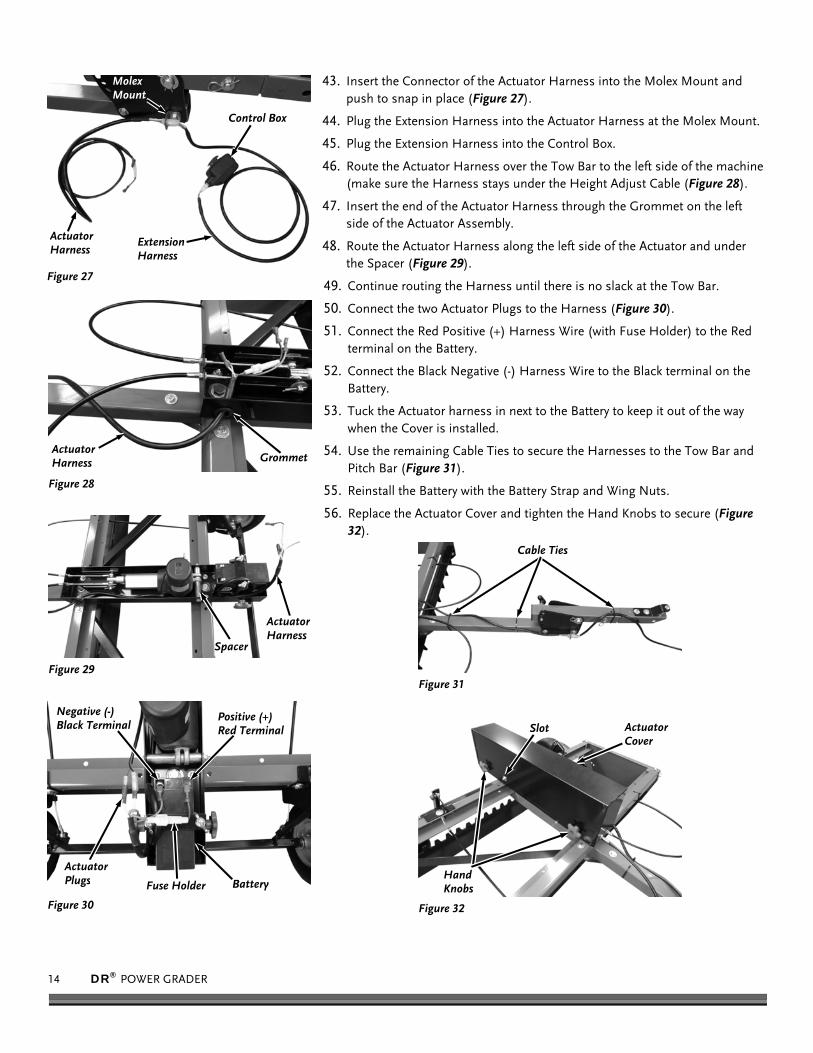
43. Insert the Connector of the Actuator Harness into the Molex Mount and push to snap in place (Figure 27).
44. Plug the Extension Harness into the Actuator Harness at the Molex Mount.
45. Plug the Extension Harness into the Control Box.
46. Route the Actuator Harness over the Tow Bar to the left side of the machine (make sure the Harness stays under the Height Adjust Cable (Figure 28).
47. Insert the end of the Actuator Harness through the Grommet on the left side of the Actuator Assembly.
48. Route the Actuator Harness along the left side of the Actuator and under the Spacer (Figure 29).
49. Continue routing the Harness until there is no slack at the Tow Bar.
50. Connect the two Actuator Plugs to the Harness (Figure 30).
51. Connect the Red Positive (+) Harness Wire (with Fuse Holder) to the Red terminal on the Battery.
52. Connect the Black Negative (-) Harness Wire to the Black terminal on the Battery.
53. Tuck the Actuator harness in next to the Battery to keep it out of the way when the Cover is installed.
54. Use the remaining Cable Ties to secure the Harnesses to the Tow Bar and Pitch Bar (Figure 31).
55. Reinstall the Battery with the Battery Strap and Wing Nuts.
56. Replace the Actuator Cover and tighten the Hand Knobs to secure (Figure 32).
Actuator Cover
Figure 32
Hand Knobs
Slot
Cable Ties
Figure 31
Battery
Figure 30
Positive (+) Red Terminal
Negative (-) Black Terminal
Actuator Plugs Fuse Holder
Actuator Harness
Figure 29
Spacer
Actuator Harness
Figure 28
Grommet
Actuator Harness
Figure 27
Extension Harness
Control Box
Molex Mount

CONTACT US AT www.DRpower.com 15
Figure 34 Ball Hitch
Latch Assembly
Connecting the DR POWER GRADER to your Tow Vehicle The following procedure is for connecting the DR POWER GRADER to your Tow Bar (Tractor) or Ball Hitch (ATV) configuration.
You should start out with the Frame of the Power Grader level to observe the performance of the grader before making any adjustments. If the Tow Bar Hitch is not at the proper height to keep the Frame of the Power Grader Level, refer to “Adjusting the Power Grader for Grading and Scarifying” on page 18 to adjust the Tow Bar Height.
Lawn Tractor: (Tow Bar Hitch)
1. Stop the Lawn Tractor Engine and set the Parking Brake.
2. Lift the Tow Bar and position the Tow Bar Hitch opening onto the Lawn Tractor Hitch Plate (Figure 33).
3. Align the hole in the center of the Hitch Plate on your Lawn Tractor with the holes in the Tow Bar Hitch. Insert the Clevis Pin and secure it with the 1/2" Washer and Hairpin.
ATV: (Tow Ball Hitch)
1. Stop the ATV engine, put the transmission in 1st gear and set the Parking Brake on your ATV
2. Pull the Latch Assembly up and into the open position. Position the Ball Hitch onto the tow vehicle’s tow ball (must be a 2" tow ball) (Figure 34).
3. Close the Latch Assembly to lock it onto the Tow Ball.
About the Battery
The DR POWER GRADER comes with a 12-Volt, maintenance-free, rechargeable, sealed lead acid Battery. Properly maintained and charged, the battery provides years of dependable service.
Figure 33
Tow Bar Hitch
Never modify your GRADER’S electrical system. Modifications could ruin the electrical system as well as cause a fire, resulting in serious injury.
Using electrical components other than those supplied with your GRADER could cause the electrical system to overheat, explode, or start a fire.
Only adults should handle the battery, it contains sulfuric acid (an electrolyte). The battery is heavy; dropping it could result in serious injury.
Never lift or carry the battery by the cables or terminals. This can damage the battery and possibly start a fire, resulting in serious injury. Lift and carry the battery only by its case.
Do not short circuit the battery. Read the safety instructions on the battery.

16 DR® POWER GRADER
Charging the Battery
Charging the Battery is a simple process. Remove the Battery from your DR POWER GRADER when you charge it.
1. Loosen the Hand Knobs and remove the Actuator Cover.
2. Disconnect the Positive (red) and Negative (black) Terminals from the Battery.
3. Remove the Thumb Screws and Battery Strap.
4. Remove the Battery from your DR POWER GRADER
5. Recharge the Battery in a dry location where the temperature is between 32°F and 78°F. For a fully discharged Battery, allow 24-48 hours to recharge.
6. Attach the Black (-) Terminal wire from the Charger Adapter to the (-) Spade of the Battery, then attach the Red (+) Terminal wire to the (+) Battery Spade.
7. Plug the Charger into a standard wall outlet.
Every time you finish using your DR POWER GRADER, recharge the Battery. The time it takes to recharge the Battery depends on how drained it is when you start. Charging the Battery typically takes 6 to 8 hours if charged after each use. However, charging may take 24 to 48 hours if you allow the Battery to run down before it is charged. The Battery does not have a “memory” so don’t worry about overcharging the Battery or charging it too often.
You can charge the Battery hundreds of times. The Battery lasts longer if you charge it before it is fully drained. Keep it fully charged and at room temperature when not using your DR POWER GRADER.
Once the Battery is charged, pull the plug from the wall outlet and then remove the Charger from your Battery. Re-connect the Positive and Negative Terminals to the Battery for use.
Store the Charger in the Box it was shipped in. Keep the charger in a dry location.
If the Battery does not hold its charge for very long under normal conditions or it simply won’t hold a charge, then replace it. You can purchase a replacement Battery directly from us. To install your new Battery, remove the Battery Clamp, detach the cables and remove the dead Battery, next install the new Battery and attach the cables, then replace the Battery Clamp.
Battery
Figure 36
Positive (+) Red Terminal
Negative (-) Black Terminal
Actuator Plugs Fuse Holder
Actuator Cover
Figure 35
Hand Knobs
Slot
Using the wrong type of battery or charger could cause a fire or explosion, resulting in serious injury. Never allow children to charge the battery. THE ELECTRICITY INVOLVED IN CHARGING THE BATTERY COULD INJURE A
CHILD. Examine the charger, its connectors, and the battery for excessive wear or damage each time you charge the battery. If you
see any excessive wear or damage, do not use the charger or the battery, replace them. Use only the 12-volt charger supplied with your grader to charge the battery. Use the charger only in dry locations. Avoid contact with water.
When the Battery gets old and no longer accepts a charge, remove it from your Grader. Never leave a dead Battery in your Grader. Dispose of an old Battery per local hazardous materials regulations. Please refer to “recycling a used battery”, on page 22, for more information.

CONTACT US AT www.DRpower.com 17
Chapter 3: Operating the DR POWER GRADER
It may be helpful to better familiarize yourself with the features of your Grader by reviewing Figure 2 in Chapter 2 before beginning the steps outlined in this chapter.
Operating Safety
Operating Parameters There are four different types of tow vehicles recommended for the DR POWER GRADER. Each vehicle type has specific strengths, weaknesses, and operating parameters when used with the DR POWER GRADER.
Garden Tractor/Lawn Tractor 14 HP and/or 400-pound tractor minimum for the 48" Model. 19 HP and/or 500-pound tractor minimum for the 60" Model. 5 slopes or less. Material loosened during grading increases traction difficulties. Very good speed control and turning radius. Frequent Scarifying Teeth adjustment may be necessary to maintain traction Forward motion of the DR POWER GRADER may need to be initiated before ground contact.
ATV Traction issues are less evident. More difficult to maintain a consistent speed of less than 5 MPH. Turning radius is large (best used for large, straight drives).
UTV Traction issues are less evident. More difficult to maintain a consistent speed of less than 5 MPH. Turning radius is large (best used for large, straight drives). The tailgate should be lowered for best visibility.
Utility Tractor Traction is excellent. Visibility is very good. With the increased power, the chance of accidentally damaging the DR POWER GRADER’s frame is increased. The
towing speed MUST be kept less than 5 MPH. Not for use with Truck or Car
Do not use these types of vehicles; the DR POWER GRADER is difficult to see. NEVER operate the DR POWER GRADER with a Truck (2WD or 4WD). Use of a Truck or Car will void the DR POWER
GRADER Warranty.
Never allow anyone to operate the DR Power Grader without first reading and understanding all instructions in this manual. Be thoroughly familiar with the controls and the proper use of your Grader before using.
Never let people ride on the Grader. Always check for objects in the Grader’s path before moving. When operating in a roadway, we suggest that you put out obstructions (marker cones or pails) to divert any traffic away from
your work area. Always be aware of potential traffic hazards.

18 DR® POWER GRADER
Operating Tips
Use additional weight (up to 80 pounds) by placing two Cinder Blocks between the Crossmembers when grading hard pack to begin scarification. A Weight Strap kit is needed to properly mount Cinder Blocks to the Grader. Call toll-free 1-800-DR-OWNER (376-9637) to order a Weight Strap Kit.
Remove any added weight such as Cinder Blocks when the surface material loosens or when experiencing traction difficulties. To create a smoother surface in soft materials, use the Drag Screen Accessory available from DR Power Equipment. Remove the weights when grading in muddy conditions or sandy soil. Expect to make several passes with the DR POWER GRADER to repair a roadway, depending on the condition. Avoid filling Pot Holes filled with water, wait until the holes are dry. Use the DR POWER GRADER to work the edges of Pot Holes that are more than 4 feet wide to loosen the sides before you
begin filling them. Avoid large rocks, embedded ledge, cattle guards, or similar obstructions. Remove rocks pulled to the surface during grading to provide a better final graded surface.
The rocks can catch under the lawn deck (lawn tractors). Once you have adequately scarified the road surface, raise the Scarifying Teeth Plate to allow the Rear Scraper (mold) Blade to
create a smooth surface. Raise the Tooth Bar Plate out of the ground before turning around or leaving the work area.
When using a lawn tractor as the tow vehicle, put the lawn mowing deck in the highest setting or just remove the deck to obtain the highest ground clearance. For ease, do your spring grading before re-installing your lawn deck for the summer mowing activity.
When using the DR POWER GRADER to prepare a seed bed, remove all large debris before grading. Use the Optional Drag Screen to create the best finish in sand or to incorporate seed.
Use Low Gear when using an ATV as the tow vehicle – Do not exceed 5 MPH while grading. The maximum speed when not grading is 10 MPH.
FAQs Question: Can the DR POWER GRADER create a crown in the road? Answer: No, but you can maintain a crown in the road by grading each side separately.
Question: Can the DR POWER GRADER ruin the crown in the road? Answer: Yes, but only if you grade down the centerline of the road.
Question: Can I use my Lawn Tractor in sandy soils? Answer: Lawn Tractors do not perform as well as an ATV or Utility Tractor in sandy soils.
Adjusting the Power Grader for Grading and Scarifying 1. Push the Button on the Control Box at the “LOWER” position to lower the
Grader fully on the ground (Figure 37). Figure 37
Toggle Switch
Raise Grader
Lower Grader
Lower the grader frame completely to the ground surface when transporting on a trailer, parking on a hill, or servicing the grader.
Frequently check the tightness of the bolts that fasten the Tooth Bar and Mold Board to the frame.

CONTACT US AT www.DRpower.com 19
2. Changing Pin Hitch positions:
a. Remove the Connectors from the Molex Mount (Figure 38).
b. Remove the Bolt, Washers and Locknut at the rear of the Pitch Plates using two 9/16" Wrenches.
c. Remove the Bolt, Molex Mount, Washers and Locknut at the front of the Pitch Plates.
d. Flip the Pitch Plate Assembly over and reinstall the Bolts, Washers, Molex Mount, and Locknuts (Figure 39).
3. Adjust the Pin Hitch Assembly as described below:
Position the Tow Bar to the highest position (on top) for low Hitch aggressive grading (Figure 39). See “Adjusting the Mold Board” for other Mold Board settings
Position the Tow Bar to the lowest position (on bottom) for tall hitch aggressive scarifying (Figure 38).
Use the remaining Tow Bar Hitch mounting positions for varying degrees of Grading and Scarifying.
Using the Mold Board ADJUSTING THE ANGLE: The Mold Board angle can be set at three different angles to determine how aggressively it moves and molds the material.
Tools Needed: Two 9/16" Wrenches
1. Remove the top Bolt and Locknut on both ends of the Mold Board using two 9/16" Wrenches (Figure 40).
2. Loosen the Bottom Bolt and Locknut using two 9/16" Wrenches so the Mold Board can be rotated.
3. Rotate the Mold Board to align with the holes at the desired setting.
4. Reinstall the top Bolts and locknuts and tighten all hardware.
CONVERTING TO SMOOTH OR GROOVED EDGE: The Mold Board can be mounted with the straight edge down for basic grading or for creating smoother surfaces in finer materials. It can also be mounted with the grooved edge down for more aggressive grading or for creating grooved surfaces in finer materials.
Tools Needed: Two 9/16" Wrenches
1. Remove the Bolts and Locknuts securing both ends of the Mold Board to the Power Grader Frame using two 9/16" Wrenches (Figure 41).
Note: The Mold Board must always be positioned with the welded angle facing toward the rear (Figure 42).
2. Remove the Mold Board and position it with the desired edge down and the welded Angle facing the rear of the machine.
3. Reinstall the Mold Board and secure with the Bolts and Locknuts.
Molex Mount and Connector
Figure 38
Bolts, Washers and Locknuts
Figure 39
Tow Bar on Top
Figure 40
Mold Board
Remove
Loosen
2 Additional Adjustment Holes
Figure 41
Mold Board
Bolts and Locknuts
Straight Edge
Welded Angle Figure 42
Grooved Edge
20 DR® POWER GRADER
Weight Strap kit
Figure 43
Crossmembers
Cinder Block
Figure 44
Toggle Switch
Raise Grader
Lower Grader
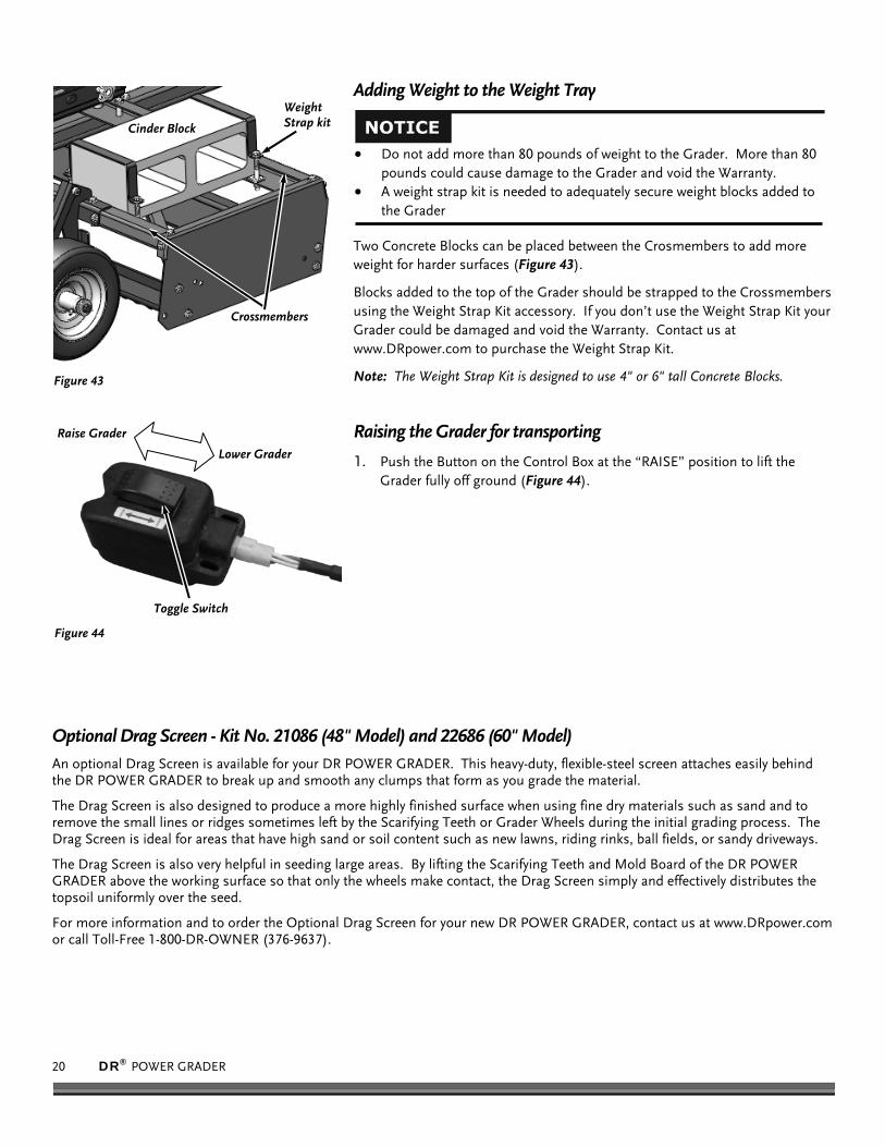
Adding Weight to the Weight Tray
Two Concrete Blocks can be placed between the Crosmembers to add more weight for harder surfaces (Figure 43).
Blocks added to the top of the Grader should be strapped to the Crossmembers using the Weight Strap Kit accessory. If you don’t use the Weight Strap Kit your Grader could be damaged and void the Warranty. Contact us at www.DRpower.com to purchase the Weight Strap Kit.
Note: The Weight Strap Kit is designed to use 4" or 6" tall Concrete Blocks.
Raising the Grader for transporting
1. Push the Button on the Control Box at the “RAISE” position to lift the Grader fully off ground (Figure 44).
Optional Drag Screen - Kit No. 21086 (48" Model) and 22686 (60" Model) An optional Drag Screen is available for your DR POWER GRADER. This heavy-duty, flexible-steel screen attaches easily behind the DR POWER GRADER to break up and smooth any clumps that form as you grade the material.
The Drag Screen is also designed to produce a more highly finished surface when using fine dry materials such as sand and to remove the small lines or ridges sometimes left by the Scarifying Teeth or Grader Wheels during the initial grading process. The Drag Screen is ideal for areas that have high sand or soil content such as new lawns, riding rinks, ball fields, or sandy driveways.
The Drag Screen is also very helpful in seeding large areas. By lifting the Scarifying Teeth and Mold Board of the DR POWER GRADER above the working surface so that only the wheels make contact, the Drag Screen simply and effectively distributes the topsoil uniformly over the seed.
For more information and to order the Optional Drag Screen for your new DR POWER GRADER, contact us at www.DRpower.com or call Toll-Free 1-800-DR-OWNER (376-9637).
Do not add more than 80 pounds of weight to the Grader. More than 80 pounds could cause damage to the Grader and void the Warranty.
A weight strap kit is needed to adequately secure weight blocks added to the Grader

CONTACT US AT www.DRpower.com 21
Chapter 4: Maintaining The DR POWER GRADER
Regular maintenance is the way to ensure the best performance and long life of your machine. Please refer to this Chapter for maintenance intervals and procedures.
Regular Maintenance Checklist
PROCEDURE BEFORE EACH USE AFTER EACH USE EVERY 25 HOURS Check tightness of Tooth Bar and Mold Board Hardware ▲
Check general equipment condition e.g., Nuts, Bolts, welds, etc. ▲
Check Actuator operation/Battery Power ▲
Hose down the DR POWER GRADER ▲
Lubricate Wheels as needed
Cleaning the Power Grader
1. Use a Hose or Power Washer to clean the DR POWER GRADER to keep the Scarifying Teeth Plate, Wheels etc. clean and clear of debris.
Caring for the Battery
Proper care can lengthen the life of a Battery. Follow these recommendations to ensure your Battery’s best performance and long life:
Do not continue to operate your DR POWER GRADER with a low Battery. Try to keep your Battery at full charge to maximize its life. If the machine is not used, charge the Battery monthly. See
“Charging the Battery” on page 16. Before charging the Battery, observe its external appearance and keep it clean and dry. Never charge or use a Battery that
shows cracks, changes shape, leaks, or otherwise obviously damaged. Recharge a Battery before fully discharged. NEVER allow the Battery to run down completely before charging. Leaving the
Battery discharged damages the Battery. Charge the Battery at least once per month, even if you have not used your DR POWER GRADER.
If the Battery begins to leak, avoid contact with the leaking acid. Place the damaged Battery in a plastic bag, then dispose of it properly. Please refer to “recycling a used battery” on page 22 for more information.
Before performing any maintenance, you must first shut off the tow vehicle, remove the key and set the parking brake.
Use care not to hose down the Battery and electrical components. Ensure the Actuator Cover is installed before using a Hose or power washer.
If Battery Acid does contact your skin or eyes, flush with cool water for at least 15 minutes and call a physician. If Acid is ingested, call a physician immediately.

22 DR® POWER GRADER
Recycling a Used Battery
Please dispose of your used Batteries responsibly by recycling them. Call your local Solid Waste Management District or your local waste handler to locate the collection site nearest you. Some collection sites recycle Batteries year-round; others collect them periodically.
You can also visit the Website of Earth 911 for more information (www.earth911.org). Once there, click Recycle Guide at the top of the page, then click the Municipal HHW link under Hazardous Household Waste, and enter your zip code. The site lists recycling centers located near you.
For a fee, you can recycle your Batteries with the International Metals Reclamation Company. Visit them at www.inmetco.com and click Services, then click Battery Recycling; or contact them at: INMETCO, One INMETCO Drive, Ellwood City, PA 16117, (724) 758-5515; fax (724) 758-2845.
To learn more about hazardous waste recycling, visit the Website for Battery Council International (www.batterycouncil.org) or for the Environmental Protection Agency (www.epa.gov).
Replacing the Tooth Bar
Tools Needed:
Two 9/16" Wrenches 3/4" Wrench 3/4" Socket with ratchet and Extension
1. Use the Control Box to raise the DR POWER GRADER off the ground.
2. Remove the Bolts and Locknuts on both ends of the Tooth Bar using two 9/16" Wrenches (Figure 46).
3. Loosen the Hand Knobs and remove the Actuator Cover.
4. Remove the Bolt, Washers and Locknut at the Tooth Bar Bracket using a 3/4" Wrench and 3/4" Socket with Ratchet and Extension.
5. Remove the old Tooth Bar and clean the mounting area of the Frame.
6. Position the new Tooth Bar and secure with the Bolts, Washers and Locknuts removed in steps 2 and 4.
7. Install the Actuator Cover.
Lubrication
Tools and Supplies Needed:
Flexible hose grease gun Lithium grease Clean Rags
1. Clean the Grease Fitting with a clean Rag (Figure 47).
2. Lubricate the Wheels at the grease fitting every 25 hours of operation.
Note: Pump the grease gun only until you feel slight resistance (2 - 3 pumps).
Tooth Bar
Figure 46
Bolts, Washers and Locknuts (Frame)
Wheels Down
Bolt, Washers and Locknut (Tooth Bar Bracket)
Actuator Cover
Grease Fitting
Figure 47
Please dispose of used batteries responsibly, according to your local hazardous materials regulations. Never throw away used batteries in your household trash.

CONTACT US AT www.DRpower.com 23
Chapter 5: Troubleshooting
Most problems are easy to fix. Consult the Troubleshooting Table below for common problems and their solutions. If you continue to experience problems, contact us at www.DRpower.com or call toll-free 1-800-DR-OWNER (376-9637) for support.
Troubleshooting Table
SYMPTOM POSSIBLE CAUSE The wheels on the tow vehicle spin during the grading operation.
The Scarifying Teeth are set too low, causing too large a section of surface to be removed. Raise the height of the Scarifying Tooth Bar to improve traction.
There is too much weight on the Crossmembers. Remove some of the weight.
The Tow Vehicle is not adequate for your application.
The Scarifying Teeth are not digging properly
The angle of the Tow Bar is not set correctly. Adjust the Tow Bar up for better grading or adjust the Tow Bar down for better scarifying.
There is not enough weight for the hardness of the surface material. Add weight (no more than 80 pounds) to the Power Grader to improve performance
The Wheels are adjusted not lifted all the way up. Raise the Wheels as needed.
The Mold Board cannot be rotated to alternate angle settings
The lower hardware is too tight. Loosen the lower Bolt and Locknut to allow the Mold Board to rotate during adjustment. Tighten all hardware when angle adjustment is done.
Before performing any maintenance, you must first shut off the tow vehicle, remove the key and set the parking brake.

24 DR® POWER GRADER
Chapter 6: Parts Lists, Schematic Diagrams and Warranty
Parts List – CONTROL BOX ASSEMBLY
NOTE: Part numbers listed are available through DR Power Equipment. Ref# Part# Description
1 38478 Actuator, Electric
2 37973 Guide, Actuator
3 38472 Pin, Actuator Guide
4 37961 Spacer, Actuator, Short
5 13447 Battery, 12v, 9ah
6 28697 Pad, Battery, 2.5" X 6.125"
7 38466 Grommet, Push In, 3/4" ID
8 37959 Spacer, Actuator, Long
9 37972 Spacer, Actuator, Middle
10 38716 Rod, Battery
11 38715 Strap, Battery
12 38933 Cover, Actuator, w/Labels
13 12683 Nut, 3/8-16, GR5, ZP
14 16413 Nut, Nylon Lock, 3/8-16, Low Profile
15 12170 Washer, Flat, 3/8", ZP, Ansi Narrow
16 22253 Washer, Lock, 3/8"
17 18064 Washer, .8" ID, 1.5" OD X .11"
18 36734 Cable, Adjust, Height, Electric
19 37965 Bracket, Axle, Mounting
20 37963 Axle, (48" Model)
37964 Axle, (60" Model)
21 17351 Bolt, HHCS, 3/8-16 X 5", GR5, ZP
22 15730 Bolt, HCS, 1/4-20 X 3/4, GR5 ZP
23 36702 Spacer, Rail
Ref# Part# Description
24 35481 Wheel, 11 X 4-5, Flat Free, Smooth Tread
25 11073 Nut, Nylon Lock, 1/4-20, ZP
26 37190 Pin, Cotter, 3/32" X 1", ZP
27 36736 Hand Control, Front
28 36303 Hand Control, Back
29 36657 Switch, Rocker
30 37748 Harness, Actuator
31 37183 Wire Harness, Tether, Extension
32 37182 Wire Harness, Control Box
33 37112 Screw, Plastic Thread Forming, Pan Head, # 2 Philips, #8-18 X 3/4", STL, ZP
34 38721 Nut, Wing, 3/8-16
35 11238 Washer, Flat, 1/4"
36 37977 Knob, Five Arm, 3/8-16
37 36737 Bolt, Shoulder, 1/2" X 3/8"L, 3/8-16
38 37239 Bolt, HHCS,3/8-16 X .75", GR5, ZP
39 16484 Bolt, HCS, 3/8-16 X 2.5", GR5, ZP
40 38720 Bolt, Shoulder, 10mm
41 38723 Nut, Nylon Lock, M8
Not Shown
38912 Label, Branding
38913 Label, Raise/Lower, Control Box
37854 Charger, Battery

CONTACT US AT www.DRpower.com 25
Schematic – CONTROL BOX ASSEMBLY

26 DR® POWER GRADER
Parts List – FRAME ASSEMBLY
NOTE: Part numbers listed are available through DR Power Equipment. Ref# Part# Description
1 37966 Rail, Frame, Right
2 37968 Rail, Frame, Left
3 38688 Crossmember, Frame, w/Label (48" Model)
37958 Crossmember, Frame, w/Label (60" Model)
4 16413 Nut, Nylon Lock, 3/8-16, Low Profile
5 36713 Tooth Bar, (48" Model)
36732 Tooth Bar, (60" Model)
6 38467 Bracket, Tooth Bar
7 36711 Board, Mold, (48" Model)
36733 Board, Mold, (60" Model)
8 38686 Bar, Tow, (48" Model)
37974 Bar, Tow, (60" Model)
9 38471 Strap, Weight Box, (48" Model)
36735 Strap, Weight Box, (60" Model)
10 37976 Plate, Pitch
11 38468 Plate, Pitch, Adjust
12 38458 Pitch Bar
13 37978 Bar, Tongue
14 38469 Pull Pin Assembly
15 38459 Strap, Pin Hitch
16 38719 Mount, Molex
17 11072 Nut, Nylon Lock, 1/2-13, GR5,ZP
18 12170 Washer, Flat 3/8, ZP, Ansi Narrow
19 23499 Washer, SAE Flat, 1/2", ZP
20 18064 Washer, .8" ID, 1.5" OD X .11"
21 38460 Bolt, HCS, 1/2-13 X 7", GR8
Ref# Part# Description
22 38461 Bolt, HCS, 1/2-13 X 4.5", GR8
23 36702 Spacer, Rail
24 37186 Spacer, Rail, Center
25 38475 Pin
26 38717 Pin, Pitch Bar
27 38718 Reusable Hairpin, Cotter Pin, 1/8" Dia, 1/2-3/4 Pin
28* 38691 Strap, Block
29* 38690 Guard, Weight Block
30 38722 Cap, Tube
31 37239 Bolt,HHCS,3/8-16 X .75",GR5 ,ZP
32 11465 Bolt, HCS Ft, 3/8-16 X 3", GR5, ZP
33 16484 Bolt, HCS, 3/8-16 X 2.5", GR5, ZP
34 38911 Bolt, 1/2-13 X 3.25", Hex Head Cap Screw, GR5 , ZP
35* 11985 Bolt, HCS, 3/8-16 X 1-1/2", GR5, ZP
36* 11075 Nut, Nylon Lock, 3/8-16, ZP
37* 17926 Bolt, 3/8-16 X 3 1/2", Full, GR5
38 16101 Hitch, Ball
39 38689 Crossmember, Frame, w/Label (Weight) (48" Model)
37960 Crossmember, Frame, w/Label (Weight) (60" Model)
* Part of Optional Accessory Weight Strap Kit #38692
Not Shown
37281 Label, Speed Limit
37284 Label, Weight Limit

CONTACT US AT www.DRpower.com 27
Schematic – FRAME ASSEMBLY

28 DR® POWER GRADER
Parts List and Schematic – DR POWER GRADER Optional Drag Screen - Kit No. 21086 (48" Model) and 22686 (60" Model)
Note: Part numbers listed are available through DR Power Equipment. Ref# Part# Description
01 21086 Drag Screen, 48", w/Chain and Links
22686 Drag Screen, 60", w/Chain and Links
02 23099 Snap, Spring, 5/16"
03 21175 Connector, Threaded
04 21177 Chain, Tangle Resistant

CONTACT US AT www.DRpower.com 29
Notes:

30 DR® POWER GRADER
Notes:

CONTACT US AT www.DRpower.com 31
DR® POWER GRADER
2-Year Limited Warranty
Terms and Conditions The DR POWER GRADER is warranted for two (2) years against defects in materials or workmanship when put to ordinary and normal consumer use; ninety (90) days for any other use.
For the purposes of all the above warranties, “ordinary and normal consumer use” refers to non-commercial residential use and does not include misuse, accidents or damage due to inadequate maintenance.
DR Power Equipment certifies that the DR POWER GRADER is fit for ordinary purposes for which a product of this type is used. DR Power Equipment however, limits the implied warranties of merchantability and fitness in duration to a period of two (2) years in consumer use, ninety (90) days for any other use.
The 2-Year Limited Warranty on the DR POWER GRADER starts on the date the machine ships from our factory. The 2-Year Limited Warranty is applicable only to the original owner.
The warranty holder is responsible for the performance of the required maintenance as defined by the manufacturer's
owner's manuals. The warranty holder is responsible for replacement of normally wearing parts such as the Battery,
Scarifying Teeth and Mold Board. Accessories to the machine are not covered by this warranty.
During the warranty period, the warranty holder is responsible for the machine transportation charges, if required.
During the warranty period, warranty parts will be shipped by standard method at no charge to the warranty holder.
Expedited shipping of warranty parts is the responsibility of the warranty holder.
SOME STATES DO NOT ALLOW LIMITATIONS ON THE LENGTH OF IMPLIED WARRANTIES, SO THE ABOVE
LIMITATIONS MAY NOT APPLY TO YOU.
DR Power Equipment shall not be liable under any circumstances for any incidental or consequential damages or expenses of any kind, including, but not limited to, cost of equipment rentals, loss of profit, or cost of hiring services to perform tasks normally performed by the DR POWER GRADER.
SOME STATES DO NOT ALLOW THE EXCLUSION OR LIMITATION OF INCIDENTAL OR CONSEQUENTIAL
DAMAGES, SO THE ABOVE LIMITATIONS MAY NOT APPLY TO YOU.
THIS WARRANTY GIVES YOU SPECIFIC LEGAL RIGHTS, AND YOU ALSO HAVE OTHER RIGHTS, WHICH VARY
FROM STATE TO STATE.

7 5 M E I G S R O A D , P . O . B O X 2 5 , V E R G E N N E S , V E R M O N T 0 5 4 9 1 ©2016 Country Home Products, Inc. All rights reserved 389461
Daily Checklist for the DR POWER GRADER To help maintain your DR POWER GRADER for optimum performance, we recommend you follow this checklist each time you use your POWER GRADER.
[ ] TOOTH BAR AND MOLD BOARD: The Tooth Bar and Mold Board endure most of the stress from the grading process. Check all nuts and bolts that secure the Tooth Bar and Mold Board to be sure that the components are secure.
[ ] HARDWARE: Check all nuts and bolts and other fasteners to be sure that all components are secure. [ ] FRAME: Check all welds to be sure that the frame is intact and secure. [ ] CLEAN: Make sure the Tooth Bar and the Frame are clean and free of debris.
End of Season and Storage
Hose down the DR POWER GRADER. Remove the Tooth Bar to clean it of debris and then replace it after cleaning the mounting surfaces.
Lubricate the Rear Wheels. Wipe down the DR POWER GRADER to remove any moisture and dirt that may have accumulated. If possible, store the Power Grader in a dry, protected place. If it is necessary to store the Power Grader outside, cover it
with a protective material. Store the Battery in a dry area that will not freeze. If you will not use the machine over a long period, charge the Battery
every four to six weeks.
Before performing any maintenance, you must first shut off the tow vehicle, remove the key and set the parking brake.
Before performing any maintenance, you must first shut off the tow vehicle, remove the key and set the parking brake.