Analytical Model for Performance Evaluation of Ablative Plasma Pulsed Thruster

29 August 2013 © Clyde Space Ltd 2011
Power Efficient Pulsed Plasma Thruster with Precise Control of High Voltage Generation
Marcos Compadre
Presented by Craig Clark
29 August 2013 © Clyde Space Ltd 2011
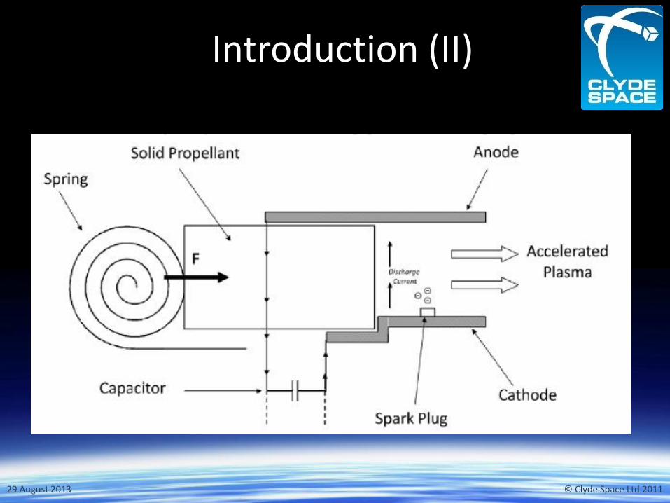
Introduction (I)
• Pulsed Plasma Thrusters (PPTs) are high-specific-impulse, low-power electric thrusters.
• Teflon used as propellant. Ablation of Teflon produces Plasma.
• High-energy storage element (some Joules). Voltage of 1-2kV,
• Igniter allows main discharge (5-10kV).
• Plasma accelerated by Lorentz force: Thrust!
• No pressure vessel to keep the launch provider happy.
29 August 2013 © Clyde Space Ltd 2011
Introduction (II)

29 August 2013 © Clyde Space Ltd 2011
Introduction (III)
• Clyde Space Ltd and Mars Space Ltd have been working together on the development of different types of PPTs for both CubeSats and Nanosatellites.
• Experience and different test campaigns allow the improvement and development of new topologies.
29 August 2013 © Clyde Space Ltd 2011
Need for Thrust
• Lifetime of LEO Nanosatellites and CubeSats limited by natural de-orbiting.
• Flight Formation.
• Attitude Control.
• Low-thrust maneuvers .

29 August 2013 © Clyde Space Ltd 2011
Requirements and Constraints
• Limited space in the satellite: Our target is to fit within a 0.3U enclosure.
• Limited power allocated: Low power consumption.
• Precise and repeatable generation of voltages.
• Low noise – conducted and emitted.
• Accurate control of the firing process.

29 August 2013 © Clyde Space Ltd 2011
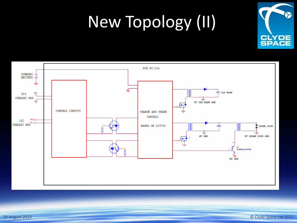
New Topology (I)
• Analog circuit for high generation of high voltages (main discharge capacitors & spark plug).
• Digital circuit to interface with the rest of the satellite and the analog circuit (MCU, Communications, Command Signals).
• Galvanic isolation between both digital and analog circuits.
29 August 2013 © Clyde Space Ltd 2011
New Topology (II)

29 August 2013 © Clyde Space Ltd 2011
Main Discharge Capacitors
• Circuit uses a Flyback topology:
– Inherent galvanic isolation between low (6V) and high voltages (1-2kV).
– Precise control of the level of charge/energy of the main discharge capacitors.

29 August 2013 © Clyde Space Ltd 2011
Spark Plug (I)
• Other circuits use voltage multipliers topologies which produce a burst of pulses.
• Our PPT uses a Flyback converter:
– Single pulse is accurately generated.
– Power consumption reduced by the use of a two stages circuit.
– Repeatability of the pulse generation.
– 5-10kV output
29 August 2013 © Clyde Space Ltd 2011
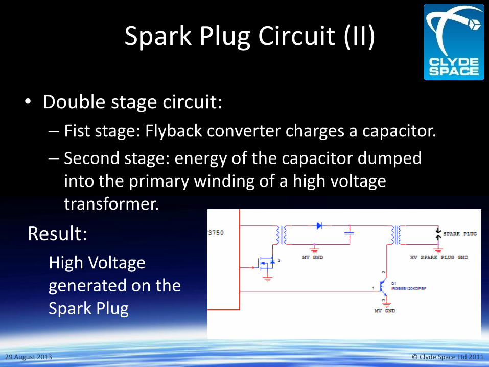
Spark Plug Circuit (II)
• Double stage circuit:
– Fist stage: Flyback converter charges a capacitor.
– Second stage: energy of the capacitor dumped into the primary winding of a high voltage transformer.
Result:
High Voltage generated on the Spark Plug

29 August 2013 © Clyde Space Ltd 2011
Digital Interface
• Interfaces with the satellite On Board Computer.
• Controls the charge of the bank of capacitors and firing sequence.
• Use of RS422 or I2C protocols.

29 August 2013 © Clyde Space Ltd 2011
Results
• The electronics have been tested with two different discharge chambers: – For Nanosatellites – For CubeSats
• Tests have been carried out in a vacuum chamber simulating real LEO conditions.
• Thrusters have undergone 1 million shots.
• Transformers designed and potted at Clyde Space.

29 August 2013 © Clyde Space Ltd 2011
Characteristics of the PPT for CubeSats
• Specific Impulse = 600s • Total Impulse: 44Ns (dV of 11m/s of a 3U (4Kg) • Impulse Bit = 40 uNs (thrust of 40uN if the PPT is fired at
1Hz) • Propellant stored on board = 7g • Voltage for digital interface
= CubeSat 3V3 Bus • Voltage for high voltage
generation = battery bus. • Final version housed in enclosure. • Available to buy now for $17,250.
29 August 2013 © Clyde Space Ltd 2011
Thank you for your interest!
Any questions?