Portada | Ministerio de Transportes, Movilidad y …...CTE Comandante CVR Registrador de voces en...
258
COMISIÓN DE INVESTIGACIÓN DE ACCIDENTES E INCIDENTES DE AVIACIÓN CIVIL CIAIAC CIAIAC Boletín Informativo 2/2013
Transcript of Portada | Ministerio de Transportes, Movilidad y …...CTE Comandante CVR Registrador de voces en...
COMISIÓN DEINVESTIGACIÓNDE ACCIDENTESE INCIDENTES DEAVIACIÓN CIVIL
CIAIACCIAIAC
BoletínInformativo
2/2013


COMISIÓN DE INVESTIGACIÓNDE ACCIDENTES E INCIDENTESDE AVIACIÓN CIVIL
SUBSECRETARÍA
BOLETÍN INFORMATIVO2/2013

Edita: Centro de PublicacionesSecretaría General TécnicaMinisterio de Fomento ©
NIPO: 161-13-023-4Depósito legal: M. 14.066-2002Diseño y maquetación: Phoenix comunicación gráfica, S. L.
COMISIÓN DE INVESTIGACIÓN DE ACCIDENTES E INCIDENTES DE AVIACIÓN CIVIL
Tel.: +34 91 597 89 63 E-mail: [email protected] C/ Fruela, 6Fax: +34 91 463 55 35 http://www.ciaiac.es 28011 Madrid (España)
A d v e r t e n c i a
El presente Boletín es un documento técnico que refleja el punto de vista dela Comisión de Investigación de Accidentes e Incidentes de Aviación Civil enrelación con las circunstancias en que se produjo el evento objeto de lainvestigación, con sus causas probables y con sus consecuencias.
De conformidad con lo señalado en el art. 5.4.1 del Anexo 13 al Conveniode Aviación Civil Internacional; y según lo dispuesto en los arts. 5.5 delReglamento (UE) n.° 996/2010, del Parlamento Europeo y del Consejo, de20 de octubre de 2010; el art. 15 de la Ley 21/2003, de Seguridad Aérea; ylos arts. 1, 4 y 21.2 del R.D. 389/1998, esta investigación tiene carácterexclusivamente técnico y se realiza con la finalidad de prevenir futurosaccidentes e incidentes de aviación mediante la formulación, si procede, derecomendaciones que eviten su repetición. No se dirige a la determinaciónni al establecimiento de culpa o responsabilidad alguna, ni prejuzga ladecisión que se pueda tomar en el ámbito judicial. Por consiguiente, y deacuerdo con las normas señaladas anteriormente la investigación ha sidoefectuada a través de procedimientos que no necesariamente se someten alas garantías y derechos por los que deben regirse las pruebas en un procesojudicial.
Consecuentemente, el uso que se haga de este Boletín para cualquierpropósito distinto al de la prevención de futuros accidentes puede derivar enconclusiones e interpretaciones erróneas.


Í n d i c e
ABREVIATURAS .............................................................................................................................................. vi
RELACIÓN DE ACCIDENTES/INCIDENTES
Referencia Fecha Matrícula Aeronave Lugar del suceso
IN-027/2009 22-10-2009 PH-DXB De Havilland Pista 25R del aeropuerto de Barcelona .. 1DHC-8-315
IN-033/2011 17-09-2011 EC-LAJ Airbus A320-214 Aeropuerto de Palma de Mallorca ........ 49LN-RRH Boeing B-737-800
IN-049/2011 03-12-2011 D-EGSK Robin DR-300/180R Aeródromo de Lillo (Toledo) ................. 89
IN-014/2012 08-05-2012 EC-IOT Piper PA-28-161 Aeropuerto de Jerez (LEJR) – Jerez ........ 101«Warrior» de la Frontera (Cádiz)
A-024/2012 01-07-2012 HA-NAH SMG-92 Turbo Finist Aeródromo de La Juliana (Sevilla) ......... 111
A-041/2012 11-11-2012 EC-JGZ Robinson R-44 Castropol (Asturias) .............................. 119
A-043/2012 25-11-2012 EC-DKJ Scheibe SF-28 Aeródromo de La Mancha (Toledo) ...... 123
ADENDA .......................................................................................................................................................... 131
(*) Versión disponible en inglés en la Adenda de este Boletín (English version available in the Addenda to this Bulletin)
Esta publicación se encuentra en Internet en la siguiente dirección:
http://www.ciaiac.es
(*)
(*)
(*)
(*)
(*)
v
Boletín informativo 2/2013
A b r e v i a t u r a s
00° Grado(s)00 °C Grados centígradosAENA Aeropuertos Españoles y Navegación AéreaAGA Aeródromos, rutas aéreas y ayudas terrestresAGL Sobre el nivel del suelo («Above Ground Level»)AIM Servicio de gestión de la información («Aeronautical Information Management»)AIO Oficina de información aeronáuticaAIP Publicación de información aeronáuticaAIRAC «Aeronautical Information Regulation And Control»AIS Servicio de información aeronáuticaAPU Unidad de potencia auxiliar («Auxiliary Power Unit»)ARC Certificado de revisión de la aeronavegabilidadARO Oficina de notificación de los servicios de tránsito aéreoARP Punto de referencia del aeródromoATC Control de tránsito aéreoATIS Servicio automático de información terminal («Automatic Terminal Information Service»)ATM Administración del Tránsito AéreoATPL(A) Piloto de transporte de línea aérea de aviónBEA Bureau d’Enquêtes et d’Analyses pour la Sécurité de l’Aviation civile (France)C/B Disyuntor eléctrico («Circuit Breaker»)CAT Categoría de aproximación instrumental («Instrument Landing Category»)CAVOK Visibilidad, nubes y condiciones meteorológicas actuales mejores que los valores o condiciones
prescritoscc Centímetro(s) cúbico(s)CIAIAC Comisión de Investigación de Accidentes e Incidentes de Aviación CivilCL Lista de chequeo («Check List»)CMD ComandanteCNS Comunicaciones, navegación y vigilanciaCPHOW Despacho de vuelos/plan de vuelo de SASCPL(A) Licencia de piloto comercial de aviónCPL(h) Licencia de piloto comercial de helicópteroCRM Gestión de recursos en cabina («Crew Resource Management»)CTE ComandanteCVR Registrador de voces en cabinaDEP SalidasDFDR Registrador digital de datos de vuelo («Digital Flight Data Recorder»)ECL Lista de chequeo de emergencia («Emergency Check List»)EGPWS Sistema de aviso de proximidad al terreno («Enhanced Ground Proximity Warning System»)EUROCONTROL Organización Europea para la Seguridad de la Navegación AéreaF/O (FO) Copiloto («First Officer»)FDR Registrador de datos de vueloFIR Región de información de vuelos («Flight Information Region»)FL Nivel de vuelo («Flight Level»)FMS Sistema de gestión de vuelo («Flight Management System»)ft Pie(s)FTE «Flight Training Europe»g Aceleración de la gravedadGMC Controlador de la torre del aeropuerto encargado de controlar el movimiento de superficieGPWS Sistema de aviso de proximidad al terrenoh Hora(s)HP Caballo(s) de vaporhPa Hectopascal(es)IAS Velocidad indicadaIFR Reglas de vuelo instrumental
Boletín informativo 2/2013
vi
Boletín informativo 2/2013
vii
A b r e v i a t u r a s
ILS Sistema de aterrizaje instrumental («Instrumental Landing System»)IR Habilitación de vuelo instrumentalJC Jefe de Cabina de pasajeroskg Kilogramo(s)KIAS Velocidad anemométrica indicada en nudoskm/h Kilómetros por horakt Nudo(s)l Litro(s)LEBL Código OACI para el aeropuerto de BarcelonaLEJR Código OACI para el aeropuerto de JerezLEPA Código OACI para el aeropuerto de Palma de MallorcaLESO Código OACI para el aeropuerto de San Sebastiánm Metro(s)MAC Cuerda media aerodinámica («Mean Aerodinamic Chord»)ME Habilitación para avión multimotorMETAR Informe meteorológico del aeropuerto («Meteorological Aviation Weather Report»)MHz Megahertzio(s)min Minuto(s)MO Manual de OperacionesMTOW Peso máximo autorizado al despegue («Maximum Take Off Weight»)N NorteNE NoresteNM Milla(s) naútica(s)NOF Oficina NOTAM internacionalNOTAM Aviso distribuido por medios de telecomunicaciones que contiene información relativa al
establecimiento, condición o modificación de cualquier instalación aeronaútica, servicio, procedimiento o peligro, cuyo conocimiento oportuno es esencial para el personal encargado de las operaciones de vuelo («Notice to Air Men»)
NW NoroesteOACI Organización de Aviación Civil InternacionalP/N Número de partePAPI Indicador de trayectoria de aproximación de precisiónPAR Licencia para lanzamiento de paracaidistas («Dropping of parachutists»)PF Piloto a los mandos («Pilot Flying»)PM Piloto supervisorPNF Piloto no a los mandos («Pilot Not Flying»)PPL(A) Licencia de piloto privado de aviónPTU Unidad de transferencia de potencia («Power Transfer Unit»)QNH Ajuste de la escala de presión para hacer que el altímetro marque la altura del aeropuerto sobre
el nivel del mar en el aterrizaje y en el despegueQRH Manual de referencia rápida («Quick Reference Handbook»)RNAV Navegación de áreaRNP Performance de navegación requerida («Required Navigation Performance»)rpm Revoluciones por minutoRWY Pistas Segundo(s)S/N Número de serieSAS Skandinavian AirlinesSAS Sistema de aumento de la estabilidad («Stability Augmentation System»)SHK Statens Haverikommission (Suecia)SOP Procedimientos operacionales estándar («Standard Operating Procedures»)SP Un solo piloto («Single Pilot»)SSW Sur suroesteTAS Velocidad verdadera respecto del aire

A b r e v i a t u r a s
TCP Tripulantes de cabina de pasajerosTGLI Licencia de piloto de planeadorTMG Motoveleros de travesíaTWR Torre de control de aeródromoUTC Tiempo Universal CoordinadoVHF Frecuencia muy alta («Very High Frequency»)Vle Velocidad con el tren de aterrizaje extendido («Velocity with Landing gear extended»)Vref Velocidad de referencia en el aterrizajeW Oeste
Boletín informativo 2/2013
viii
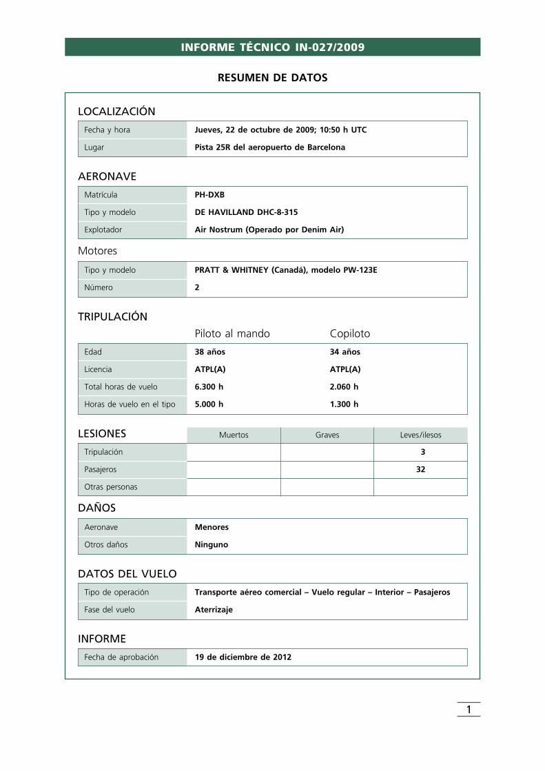
LOCALIZACIÓN
Fecha y hora Jueves, 22 de octubre de 2009; 10:50 h UTC
Lugar Pista 25R del aeropuerto de Barcelona
DATOS DEL VUELO
Tipo de operación Transporte aéreo comercial – Vuelo regular – Interior – Pasajeros
Fase del vuelo Aterrizaje
INFORME
Fecha de aprobación 19 de diciembre de 2012
TRIPULACIÓN
Piloto al mando Copiloto
Edad 38 años 34 años
Licencia ATPL(A) ATPL(A)
Total horas de vuelo 6.300 h 2.060 h
Horas de vuelo en el tipo 5.000 h 1.300 h
AERONAVE
Matrícula PH-DXB
Tipo y modelo DE HAVILLAND DHC-8-315
Explotador Air Nostrum (Operado por Denim Air)
Motores
Tipo y modelo PRATT & WHITNEY (Canadá), modelo PW-123E
Número 2
LESIONES Muertos Graves Leves /ilesos
Tripulación 3
Pasajeros 32
Otras personas
DAÑOS
Aeronave Menores
Otros daños Ninguno
RESUMEN DE DATOS
INFORME TÉCNICO IN-027/2009
1
1. INFORMACIÓN FACTUAL
1.1. Reseña del vuelo
El día 22 de octubre de 2009, la aeronave De Havilland DHC8-315, matrícula PH-DXB,realizaba un vuelo regular de pasajeros con salida en el aeropuerto de Barcelona (LEBL)y destino al aeropuerto de San Sebastián (LESO). Estaba operado por Denim Air para AirNostrum y tenía el indicativo de vuelo ANS-8852. A bordo iban dos pilotos, unatripulante de cabina de pasajeros (TCP) y treinta y dos pasajeros.
Las condiciones meteorológicas en el aeropuerto de Barcelona eran, en algún grado,adversas al encontrarse varios núcleos tormentosos en los alrededores, con lluvia, a ratosintensa. La situación de tráfico estaba también afectada por diversas demoras en lassalidas y las llegadas debido a esas tormentas.
El vuelo ANS-8852 inició su rodadura con diez minutos de retraso, a las 10:15 UTC1 concombustible suficiente para hacer la ruta de ida y vuelta a San Sebastián. La comandanteactuaba como piloto a los mandos (PF). La aeronave despegó por la pista 25 L a las10:27, se fue al aire con toda normalidad y la tripulación seleccionó tren arriba.
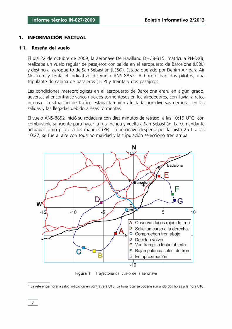
Figura 1. Trayectoria del vuelo de la aeronave
1 La referencia horaria salvo indicación en contra será UTC. La hora local se obtiene sumando dos horas a la hora UTC.
Boletín informativo 2/2013Informe técnico IN-027/2009
2
Unos 3 minutos más tarde la tripulación observó que estaban encendidas las tres lucesrojas de tren inseguro. Solicitaron a la TCP la comprobación visual de posición de laspatas de tren principal. Aquella les confirmó que las dos patas izquierda y derechaseguían desplegadas abajo.
La aeronave hasta esos momentos del vuelo continuaba ascendiendo y acelerando,habiendo alcanzado los 7.500 ft de altitud y 199 KIAS de velocidad. Decidieron volvera Barcelona mientras intentaban repasar los procedimientos y asegurarse de que el trense configuraba adecuadamente para la toma, desplegándolo por el sistema alternativoo de emergencia.
ATC recibió información de que el avión volvía con problemas de tren y le facilitó suintegración en la secuencia de aterrizaje dándole el número dos.
En un momento determinado del proceso para la extensión alternativa del tren, la tripulación advirtió que la trampilla-techo («landing gear alternate release door») estaba abierta, cuando su posición normal es cerrada. Instintivamente cerraronla trampilla-techo tras lo que se oyeron ruidos «alarmantes y estrepitosos», según ladeclaración de los propios pilotos, por lo que la volvieron a abrir. Continuaron con elprocedimiento alternativo de extensión de tren en vuelo, posicionando la palancaselectora en su posición de tren abajo. Medio minuto más tarde la aeronave seincorporaba a la aproximación final interrumpiendo de nuevo el procedimiento.
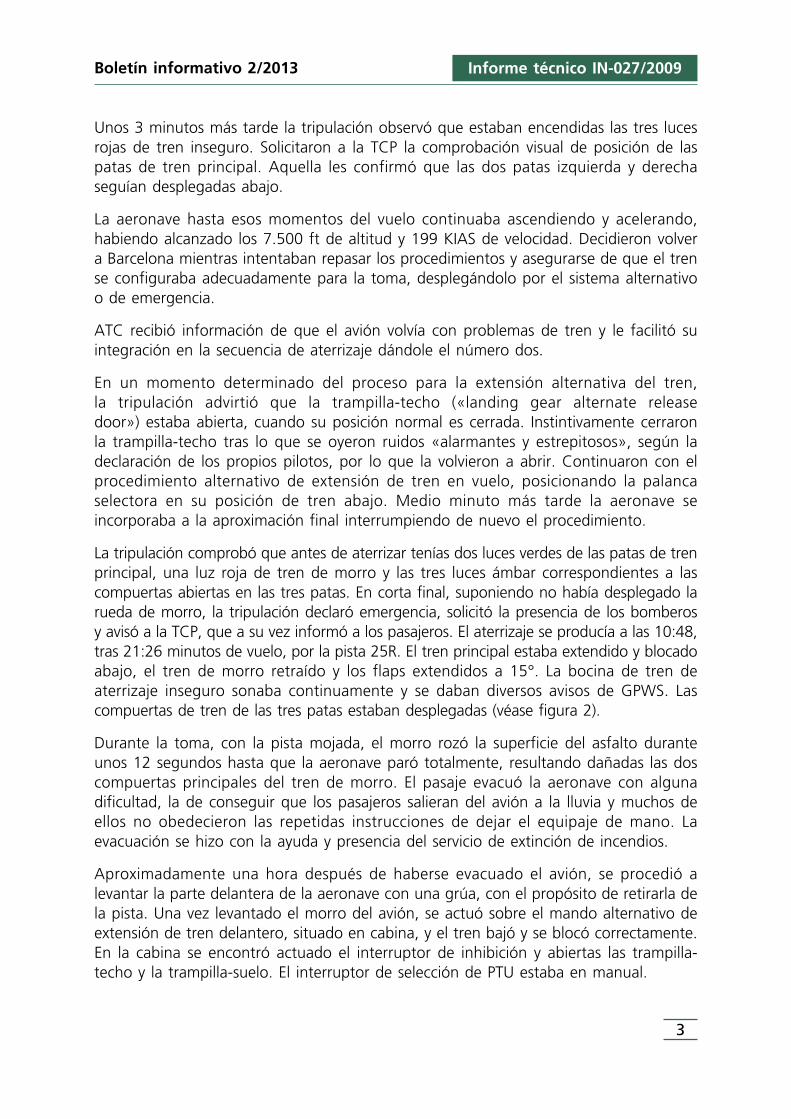
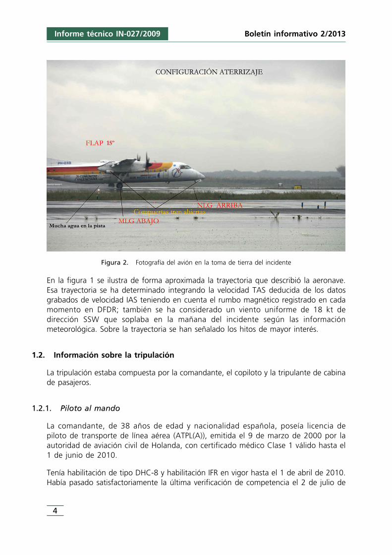
La tripulación comprobó que antes de aterrizar tenías dos luces verdes de las patas de trenprincipal, una luz roja de tren de morro y las tres luces ámbar correspondientes a lascompuertas abiertas en las tres patas. En corta final, suponiendo no había desplegado larueda de morro, la tripulación declaró emergencia, solicitó la presencia de los bomberosy avisó a la TCP, que a su vez informó a los pasajeros. El aterrizaje se producía a las 10:48,tras 21:26 minutos de vuelo, por la pista 25R. El tren principal estaba extendido y blocadoabajo, el tren de morro retraído y los flaps extendidos a 15°. La bocina de tren deaterrizaje inseguro sonaba continuamente y se daban diversos avisos de GPWS. Lascompuertas de tren de las tres patas estaban desplegadas (véase figura 2).
Durante la toma, con la pista mojada, el morro rozó la superficie del asfalto duranteunos 12 segundos hasta que la aeronave paró totalmente, resultando dañadas las doscompuertas principales del tren de morro. El pasaje evacuó la aeronave con algunadificultad, la de conseguir que los pasajeros salieran del avión a la lluvia y muchos deellos no obedecieron las repetidas instrucciones de dejar el equipaje de mano. Laevacuación se hizo con la ayuda y presencia del servicio de extinción de incendios.
Aproximadamente una hora después de haberse evacuado el avión, se procedió alevantar la parte delantera de la aeronave con una grúa, con el propósito de retirarla dela pista. Una vez levantado el morro del avión, se actuó sobre el mando alternativo deextensión de tren delantero, situado en cabina, y el tren bajó y se blocó correctamente.En la cabina se encontró actuado el interruptor de inhibición y abiertas las trampilla-techo y la trampilla-suelo. El interruptor de selección de PTU estaba en manual.
Boletín informativo 2/2013
3
Informe técnico IN-027/2009
4
Informe técnico IN-027/2009 Boletín informativo 2/2013
Figura 2. Fotografía del avión en la toma de tierra del incidente
En la figura 1 se ilustra de forma aproximada la trayectoria que describió la aeronave.Esa trayectoria se ha determinado integrando la velocidad TAS deducida de los datosgrabados de velocidad IAS teniendo en cuenta el rumbo magnético registrado en cadamomento en DFDR; también se ha considerado un viento uniforme de 18 kt dedirección SSW que soplaba en la mañana del incidente según las informaciónmeteorológica. Sobre la trayectoria se han señalado los hitos de mayor interés.
1.2. Información sobre la tripulación
La tripulación estaba compuesta por la comandante, el copiloto y la tripulante de cabinade pasajeros.
1.2.1. Piloto al mando
La comandante, de 38 años de edad y nacionalidad española, poseía licencia de piloto de transporte de línea aérea (ATPL(A)), emitida el 9 de marzo de 2000 por laautoridad de aviación civil de Holanda, con certificado médico Clase 1 válido hasta el1 de junio de 2010.
Tenía habilitación de tipo DHC-8 y habilitación IFR en vigor hasta el 1 de abril de 2010.Había pasado satisfactoriamente la última verificación de competencia el 2 de julio de
Informe técnico IN-027/2009
5
Boletín informativo 2/2013
2009, la última supervisión en línea («Line Check») el 18 de abril de 2009 y el últimorefresco CRM el 1 de diciembre de 2008.
La comandante acumulaba un total de 6.300 h de vuelo, de las que aproximadamente5.000 eran en aeronaves del mismo tipo DHC-8. Durante los últimos 30 días habíavolado 16:20 h y durante las últimas 24 horas había volado 6 horas. Este era el primervuelo del día para ella, habiendo iniciado la actividad a las 09:20 h, 45 minutos antesdel vuelo programado para las 10:05 h de la mañana.
1.2.2. Copiloto
El copiloto, de 34 años de edad y nacionalidad española, poseía licencia de piloto de transporte de línea aérea (ATPL (A)), emitida el 11 de agosto de 2009 por laautoridad de aviación civil de Holanda, con certificado médico Clase 1 válido hasta el7 de marzo de 2010.
Tenía habilitación de tipo DHC-8 y habilitación IFR en vigor desde el 1 de agosto de2009, había obtenido la habilitación de aeronave multimotor el 7 de junio de 2007.Había pasado satisfactoriamente la verificación de competencia el 26 de julio de 2009,la supervisión en línea había sido el 15 de mayo de 2009 y el curso CRM se realizó el7 de octubre de 2009.
El copiloto acumulaba un total de 2.060 h de vuelo, de las que aproximadamente1.300 h eran en aeronaves del mismo tipo DHC-8. Durante los últimos 30 días habíavolado 62:10 h y durante las últimas 24 horas había volado 2:57 h, de las cuales 1:33 hcorrespondían a un vuelo en la misma mañana y con la misma aeronave desde SanSebastián a Barcelona, habiendo iniciado su actividad a las 4:45 h de la mañana.
1.2.3. Tripulación de cabina de pasajeros
La tripulación de cabina de pasajeros era de solo una persona con licencia tripulante decabina de pasajeros (TCP). Inició su actividad a las 4:45 h de la mañana pues habíavenido en el vuelo desde San Sebastián a Barcelona. La escala en este aeropuerto habíasido de tres horas de duración.
1.3. Información sobre la aeronave
1.3.1. General
El avión De Havilland Canadá DHC-8-315 DASH 8 es una aeronave de ala alta que seconcibió para su uso en el transporte aéreo regional de corto alcance y obtuvo sucertificado de tipo en 1985.
Actualmente el poseedor del Certificado de Tipo es Bombardier Inc.
6
Informe técnico IN-027/2009 Boletín informativo 2/2013
El avión del incidente, con matrícula PH-DXB, holandesa, tiene número de serie 589.Su peso máximo al despegue (MTOW) es de 19.495 kg y tiene una configuración de50 pasajeros. Está dotado con dos motores turbohélice PRATT & WITHNEY (Canadá)modelo PW123E, que desarrollan una potencia de 2.380 HP.
1.3.2. Estado de mantenimiento
La aeronave del incidente contaba con el correspondiente certificado de revisión de laaeronavegabilidad que caducaba el 18 de mayo de 2010.
Los datos de mantenimiento recopilados mostraban que la aeronave había acumulado14.150 h de vuelo en 16.943 ciclos.
Se encontraba al día de todas las tareas de mantenimiento programadas y su últimarevisión mayor se había realizado en Valencia, en julio de 2007, cuando la aeronavecumplía las 9.572 h y 11.562 ciclos. Las últimas tareas de mantenimiento consistieron enel cambio de la rueda número 2 de la pata izquierda del tren principal y una revisión de75 h. Quedaban pendientes de corregir dos defectos diferidos, que requerían el cambiode un equipo de FMS («Flight Management System») y sustitución del panel de audio #1.
1.3.3. Peso y centrado
La hoja de carga que se confeccionó en el aeropuerto de Barcelona para el despachode la aeronave registraba los siguientes pesos:
• Carga total del vuelo: 2.798 kg• Peso de operación en vacío: 12.592 kg• Peso con combustible cero actual: 15.390 kg. Máximo: 17.917 kg• Combustible para el despegue: 2.450 kg• Peso de despegue actual: 17.840 kg. Máximo: 19.495 kg• Combustible a consumir en el vuelo: 800 kg• Peso previsto al aterrizaje: 17.040 kg. Máximo: 19.051 kg
— Centrado al despegue: 26,98 %MAC; mín. 20%;,0 máx. 40%— Centrado al aterrizaje: 26,61 %MAC; mín. 19,5%; máx. 40%
Para el centrado se ha supuesto 13 pasajeros en filas 1 a 7 y 19 pasajeros en filas 8 a19 de acuerdo con la hoja de carga.
Para las condiciones de carga y peso de la aeronave se estima que el paso de la mitadde los pasajeros de las filas anteriores de la cabina de vuelo a las filas posterioresproduce un desplazamiento del centro de gravedad, hacia atrás, de un 4% o 5% MAC.Ese desplazamiento podría ocasionar una disminución de la carga sobre la rueda demorro de unos 200 kg.
Informe técnico IN-027/2009
7
Boletín informativo 2/2013
La velocidad de aproximación con 15° de flap y estas condiciones de carga (Vref) erade 105 kt según el manual de operaciones.
1.3.4. Información sobre el tren de aterrizaje
Este tipo de avión tiene tren triciclo retráctil con dos ruedas en cada pata. Las patasprincipales, alojadas en las góndolas de los motores debajo de los planos cuando estánretraídas, se despliegan hacia delante, contra el viento. La pata de morro se despliegagirando hacia atrás.
Tanto la pata de morro como las principales tienen dos compuertas que se abren parapermitir el paso de las ruedas en sus movimientos de extensión y retracción y quevuelven a cerrarse cuando han pasado, hacia arriba o hacia abajo. Existen además otrasdos compuertas en cada pata que se mueven arrastradas por la propia pata. Se puedecontrolar la orientación de las ruedas de la pata de morro mediante los pedales ytambién con una rueda (tiller) situada en el lado del comandante.
El avión no debe superar los 173 kt (IAS) de velocidad con el tren desplegado.
1.3.4.1. Accionamiento normal del tren de aterrizaje
El avión dispone de dos sistemas hidráulicos independientes, y cada uno de ellos esoperado tomando energía de uno de los dos motores. El tren de aterrizaje está operadoconcretamente por el sistema n.° 2, el cual toma la energía de la bomba hidráulica delmotor derecho. Cada una de las patas está equipada con un martinete o actuadorhidráulico. Las patas principales tienen un segundo martinete auxiliar accionado por unabomba hidráulica manual.
En el panel de tren de aterrizaje en cabina de vuelo se ubica la palanca selectora de trenarriba y abajo y un conjunto de nueve luces distribuidas en tres filas y tres columnas. Lapalanca selectora de tren tiene dos posiciones (arriba o abajo) y gobierna eléctricamenteuna válvula selectora de tren que dirige la presión hidráulica del sistema #2 en ladirección de subir o de bajar, respectivamente.
Las nueve luces indican la posición en la que se encuentra cada una de las patas y suscompuertas (columna central para la pata de morro y columnas laterales para las patasizquierda y derecha). Las luces de la primera fila son de color ámbar y su iluminaciónindica que la compuerta correspondiente está abierta. Las luces de la segunda y tercerafila son verdes y rojas respectivamente. Si se ilumina una luz verde la patacorrespondiente del tren está abajo y blocada. Una luz de color rojo indica que la patacorrespondiente del tren no está blocada o no está en una posición coherente con laseleccionada en la palanca de cabina.
La palanca que sirve para accionar el tren también se ilumina con una luz ámbar. Sise enciende a la vez que se activan las de color rojo, indica que el tren se encuentra
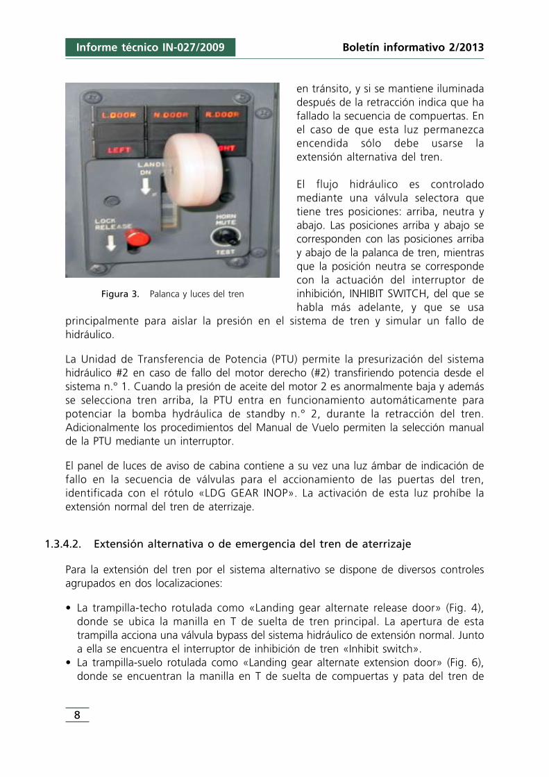
en tránsito, y si se mantiene iluminadadespués de la retracción indica que hafallado la secuencia de compuertas. Enel caso de que esta luz permanezcaencendida sólo debe usarse laextensión alternativa del tren.
El flujo hidráulico es controladomediante una válvula selectora quetiene tres posiciones: arriba, neutra yabajo. Las posiciones arriba y abajo secorresponden con las posiciones arribay abajo de la palanca de tren, mientrasque la posición neutra se correspondecon la actuación del interruptor deinhibición, INHIBIT SWITCH, del que sehabla más adelante, y que se usa
principalmente para aislar la presión en el sistema de tren y simular un fallo dehidráulico.
La Unidad de Transferencia de Potencia (PTU) permite la presurización del sistemahidráulico #2 en caso de fallo del motor derecho (#2) transfiriendo potencia desde elsistema n.° 1. Cuando la presión de aceite del motor 2 es anormalmente baja y ademásse selecciona tren arriba, la PTU entra en funcionamiento automáticamente parapotenciar la bomba hydráulica de standby n.° 2, durante la retracción del tren.Adicionalmente los procedimientos del Manual de Vuelo permiten la selección manualde la PTU mediante un interruptor.
El panel de luces de aviso de cabina contiene a su vez una luz ámbar de indicación defallo en la secuencia de válvulas para el accionamiento de las puertas del tren,identificada con el rótulo «LDG GEAR INOP». La activación de esta luz prohíbe laextensión normal del tren de aterrizaje.
1.3.4.2. Extensión alternativa o de emergencia del tren de aterrizaje
Para la extensión del tren por el sistema alternativo se dispone de diversos controlesagrupados en dos localizaciones:
• La trampilla-techo rotulada como «Landing gear alternate release door» (Fig. 4),donde se ubica la manilla en T de suelta de tren principal. La apertura de estatrampilla acciona una válvula bypass del sistema hidráulico de extensión normal. Juntoa ella se encuentra el interruptor de inhibición de tren «Inhibit switch».
• La trampilla-suelo rotulada como «Landing gear alternate extension door» (Fig. 6),donde se encuentran la manilla en T de suelta de compuertas y pata del tren de
Figura 3. Palanca y luces del tren
8
Informe técnico IN-027/2009 Boletín informativo 2/2013
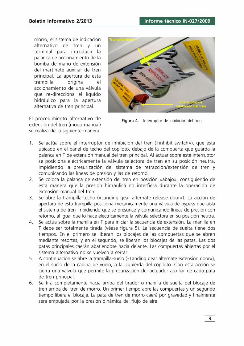
morro, el sistema de indicaciónalternativo de tren y unterminal para introducir lapalanca de accionamiento de labomba de mano de extensióndel martinete auxiliar de trenprincipal. La apertura de estatrampilla origina elaccionamiento de una válvulaque re-direcciona el líquidohidráulico para la aperturaalternativa de tren principal.
El procedimiento alternativo deextensión del tren (modo manual)se realiza de la siguiente manera:
1. Se actúa sobre el interruptor de inhibición del tren («inhibit switch»), que estáubicado en el panel de techo del copiloto, debajo de la compuerta que guarda lapalanca en T de extensión manual del tren principal. Al actuar sobre este interruptorse posiciona eléctricamente la válvula selectora de tren en su posición neutra,impidiendo la presurización del sistema de retracción/extensión de tren ycomunicando las líneas de presión y las de retorno.
2. Se coloca la palanca de extensión del tren en posición «abajo», consiguiendo deesta manera que la presión hidráulica no interfiera durante la operación deextensión manual del tren
3. Se abre la trampilla-techo («Landing gear alternate release door»). La acción deapertura de esta trampilla posiciona mecánicamente una válvula de bypass que aíslael sistema de tren impidiendo que se presurice y comunicando líneas de presión conretorno, al igual que lo hace eléctricamente la válvula selectora en su posición neutra.
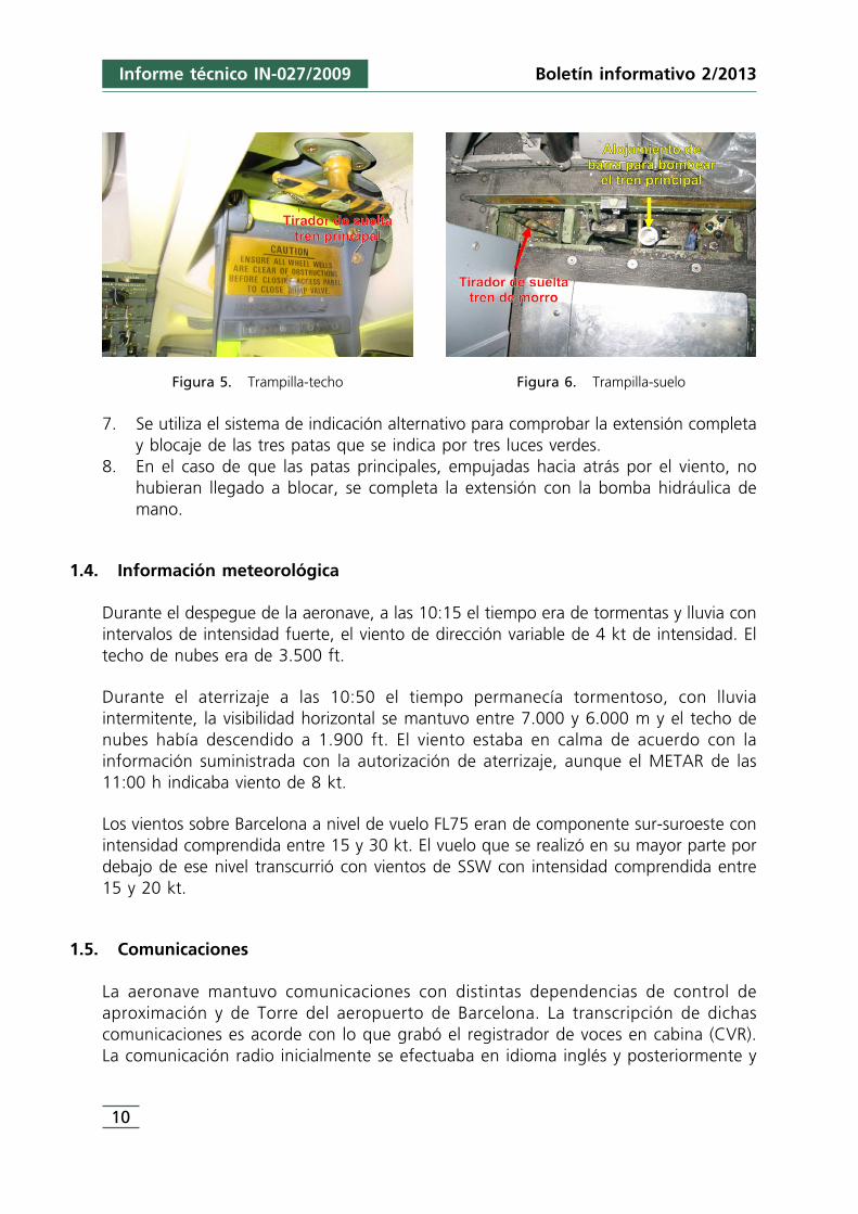
4. Se actúa sobre la manilla en T para iniciar la secuencia de extensión. La manilla enT debe ser totalmente tirada (véase figura 5). La secuencia de suelta tiene dostiempos. En el primero se liberan los blocajes de las compuertas que se abrenmediante resortes, y en el segundo, se liberan los blocajes de las patas. Las dospatas principales caerán abatiéndose hacia delante. Las compuertas abiertas por elsistema alternativo no se vuelven a cerrar.
5. A continuación se abre la trampilla-suelo («Landing gear alternate extension door»),en el suelo de la cabina de vuelo, a la izquierda del copiloto. Con esta acción secierra una válvula que permite la presurización del actuador auxiliar de cada patade tren principal.
6. Se tira completamente hacia arriba del tirador o manilla de suelta del blocaje detren arriba del tren de morro. Un primer tiempo abre las compuertas y un segundotiempo libera el blocaje. La pata de tren de morro caerá por gravedad y finalmenteserá empujada por la presión dinámica del flujo de aire.
Figura 4. Interruptor de inhibición del tren
Informe técnico IN-027/2009
9
Boletín informativo 2/2013
10
Informe técnico IN-027/2009 Boletín informativo 2/2013
Figura 5. Trampilla-techo Figura 6. Trampilla-suelo
7. Se utiliza el sistema de indicación alternativo para comprobar la extensión completay blocaje de las tres patas que se indica por tres luces verdes.
8. En el caso de que las patas principales, empujadas hacia atrás por el viento, nohubieran llegado a blocar, se completa la extensión con la bomba hidráulica demano.
1.4. Información meteorológica
Durante el despegue de la aeronave, a las 10:15 el tiempo era de tormentas y lluvia conintervalos de intensidad fuerte, el viento de dirección variable de 4 kt de intensidad. Eltecho de nubes era de 3.500 ft.
Durante el aterrizaje a las 10:50 el tiempo permanecía tormentoso, con lluviaintermitente, la visibilidad horizontal se mantuvo entre 7.000 y 6.000 m y el techo denubes había descendido a 1.900 ft. El viento estaba en calma de acuerdo con lainformación suministrada con la autorización de aterrizaje, aunque el METAR de las11:00 h indicaba viento de 8 kt.
Los vientos sobre Barcelona a nivel de vuelo FL75 eran de componente sur-suroeste conintensidad comprendida entre 15 y 30 kt. El vuelo que se realizó en su mayor parte pordebajo de ese nivel transcurrió con vientos de SSW con intensidad comprendida entre15 y 20 kt.
1.5. Comunicaciones
La aeronave mantuvo comunicaciones con distintas dependencias de control deaproximación y de Torre del aeropuerto de Barcelona. La transcripción de dichascomunicaciones es acorde con lo que grabó el registrador de voces en cabina (CVR).La comunicación radio inicialmente se efectuaba en idioma inglés y posteriormente y
Informe técnico IN-027/2009
11
Boletín informativo 2/2013
una vez cambiado el plan de vuelo y regreso al aeródromo se cambió al idiomaespañol.
En el punto 1.7.1. Registrador de Voces de Cabina (CVR) se han sincronizado ysecuenciado las comunicaciones radio con las conversaciones de cabina para generar lasecuencia de acontecimientos considerados significativos durante el vuelo.
1.6. Información sobre el aeródromo
El aeropuerto de Barcelona-El Prat está situado al sur de la ciudad, junto al mar, y tieneuna elevación de 14 ft. Dispone de tres pistas que están designadas como 25R-07L,20-02 y la 25L-07R. Las dos primeras se cruzan entre sí.
La pista donde aterrizó el vuelo del incidente fue la 25R, cuya longitud es 3.352 m y 60m de anchura. La elevación de la cabecera es de 10 ft. Dispone de ayuda visual PAPIde senda de planeo y de ayuda instrumental ILS CAT II/III. Tanto la senda visual comola del ILS tienen una pendiente de 3°.
1.7. Registradores de vuelo
1.7.1. Registrador de voces de cabina (CVR)
La aeronave llevaba instalado un registrador de voces de cabina (CVR) de memoria enestado sólido. El tiempo máximo que podía grabar era de 120 minutos.
Del tratamiento del registrador en laboratorio se obtuvieron cuatro pistas de audio,correspondientes a los canales de sonido del micrófono del comandante, el micrófonodel copiloto, el micrófono de ambiente y un cuarto canal que es mezcla de los otrostres.
El idioma utilizado en cabina de vuelo para el intercambio de información entre latripulación era el castellano, aunque las listas de chequeo y términos específicos de laoperación de la aeronave se mantenían en idioma inglés, idioma prioritario del operadorDenim Air.
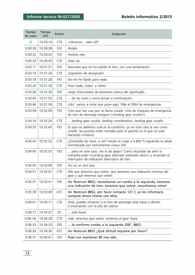
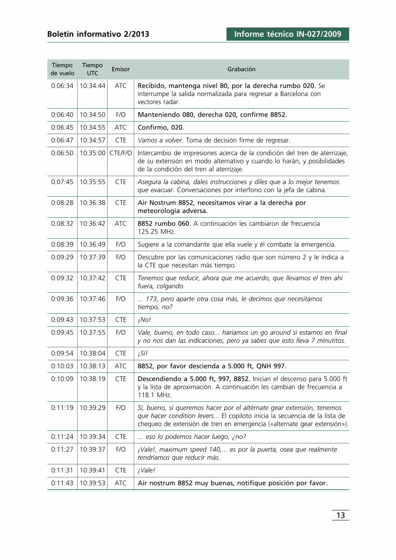
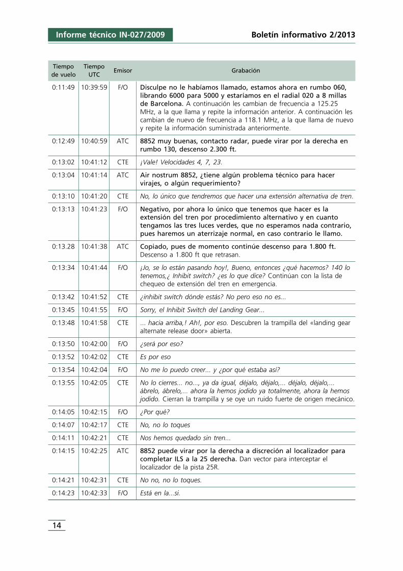
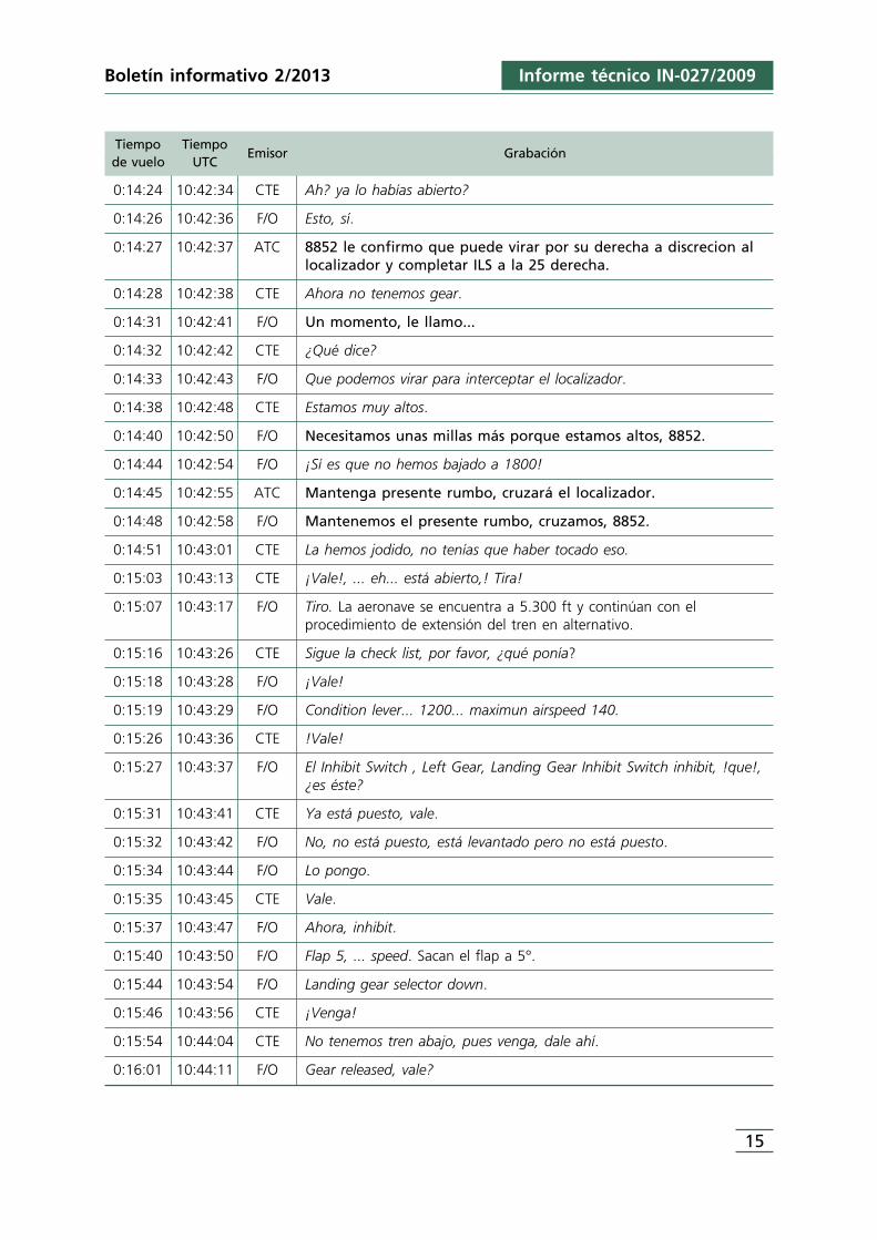
En la siguiente tabla se resumen las conversaciones más relevantes relacionadas con elincidente que quedaron registradas en la pista que es mezcla de los tres canales. Lareferencia horaria es el tiempo de vuelo transcurrido desde la suelta de frenos hasta elmomento en el que se registra la grabación. En el texto se utiliza letra cursiva para lascomunicaciones internas literales entre la tripulación, letra normal para lasobservaciones, aclaraciones o compendio no literal de la comunicación o acciónrealizada, y letra negrita para las comunicaciones radio literales.
12
Informe técnico IN-027/2009 Boletín informativo 2/2013
Tiempo Tiempode vuelo UTC
Emisor Grabación
0 10:28:10 CTE ¡Vámonos... take off!
0:00:28 10:28:38 F/O Rotate.
0:00:32 10:28:42 F/O Positive rate.
0:00:33 10:28:43 CTE Gear up.
0:03:11 10:31:21 F/O Descubre que no ha subido el tren, con una exclamación.
0:03:16 10:31:26 CTE ¡Expresión de desagrado!
0:03:18 10:31:28 F/O No me he fijado para nada.
0:03:20 10:31:30 CTE Pues nada, ¡hala!, a volver.
0:03:26 10:31:36 F/O Largo intercambio de pareceres acerca del significado...
0:03:42 10:31:52 CTE ... de las luces y como actuar a continuación.
0:03:46 10:31:56 CTE ¡No!, vamos a mirar que pone aquí. Pide el QRH de emergencias.
0:03:59 10:32:09 F/O Creo que hay una que se llama unsafe. Lista de chequeo de emergenciade tren de aterrizaje inseguro («landing gear unsafe»).
0:04:16 10:32:26 CTE ... landing gear unsafe, landing consideration, landing gear unsafe.
0:04:35 10:32:45 F/O Es que no sabemos cuál es la condición, yo en este caso la veo comounsafe, las puertas están cerradas pero el gancho es el que no estáhaciendo contacto.
0:04:42 10:32:52 CTE ¿Enciendes las luces, a ver? Inician el viraje a 5.800 ft siguiendo la salidanormalizada por instrumentos Graus 2W.
0:04:45 10:32:55 F/O ... pero en este caso, me lo da abajo? Como resultado de abrir latrampilla-suelo («Landing gear alternate extensión door») y encender elinterruptor de indicación alternativo de tren.
0:04:50 10:33:00 F/O Eso es un test solo.
0:04:51 10:33:01 CTE Dile que tenemos que volver, que tenemos una indicación errónea delgear y que tenemos que volver.
0:05:31 10:33:41 F/O Air Nostrum 8852, necesitamos un rumbo a la izquierda, tenemosuna indicación de tren, tenemos que volver, necesitamos volver.
0:05:39 10:33:49 ATC Air Nostrum 8852, por favor contacte 127.7, yo les informaré,contacte ahora mismo con ellos.
0:06:01 10:34:11 CTE Hola, puedes mirarme si el tren de aterrizaje está fuera o dentro.Conversación con la jefa de cabina.
0:06:17 10:34:27 J/C ... está fuera.
0:06:18: 10:34:28 CTE Vale, tenemos que volver, tenemos el gear fuera.
0:06:23 10:34:33 F/O ... le confirmo rumbo a la izquierda 200°, 8852.
0:06:26 10:34:36 ATC Air Nostrum 8852 ¿Qué altitud requiere por favor?
0:06:31 10:34:41 F/O Pues con mantener 80 nos vale.
Informe técnico IN-027/2009
13
Boletín informativo 2/2013
Tiempo Tiempode vuelo UTC
Emisor Grabación
0:06:34 10:34:44 ATC Recibido, mantenga nivel 80, por la derecha rumbo 020. Seinterrumpe la salida normalizada para regresar a Barcelona con vectores radar.
0:06:40 10:34:50 F/O Manteniendo 080, derecha 020, confirme 8852.
0:06:45 10:34:55 ATC Confirmo, 020.
0:06:47 10:34:57 CTE Vamos a volver. Toma de decisión firme de regresar.
0:06:50 10:35:00 CTE/F/O Intercambio de impresiones acerca de la condición del tren de aterrizaje,de su extensión en modo alternativo y cuando lo harán, y posibilidadesde la condición del tren al aterrizaje.
0:07:45 10:35:55 CTE Asegura la cabina, dales instrucciones y diles que a lo mejor tenemosque evacuar. Conversaciones por interfono con la jefa de cabina.
0:08:28 10:36:38 CTE Air Nostrum 8852, necesitamos virar a la derecha pormeteorología adversa.
0:08:32 10:36:42 ATC 8852 rumbo 060. A continuación les cambiaron de frecuencia 125.25 MHz.
0:08:39 10:36:49 F/O Sugiere a la comandante que ella vuele y él combate la emergencia.
0:09:29 10:37:39 F/O Descubre por las comunicaciones radio que son número 2 y le indica ala CTE que necesitan más tiempo.
0:09:32 10:37:42 CTE Tenemos que reducir, ahora que me acuerdo, que llevamos el tren ahífuera, colgando.
0:09:36 10:37:46 F/O ... 173, pero aparte otra cosa más, le decimos que necesitamos tiempo, no?
0:09:43 10:37:53 CTE ¡No!
0:09:45 10:37:55 F/O Vale, bueno, en todo caso... haríamos un go around si estamos en finaly no nos dan las indicaciones, pero ya sabes que esto lleva 7 minutitos.
0:09:54 10:38:04 CTE ¡Sí!
0:10:03 10:38:13 ATC 8852, por favor descienda a 5.000 ft, QNH 997.
0:10:09 10:38:19 CTE Descendiendo a 5.000 ft, 997, 8852. Inician el descenso para 5.000 fty la lista de aproximación. A continuación les cambian de frecuencia a118.1 MHz.
0:11:19 10:39:29 F/O Sí, bueno, si queremos hacer por el altérnate gear extensión, tenemosque hacer condition levers... El copiloto inicia la secuencia de la lista dechequeo de extensión de tren en emergencia («alternate gear extensión»).
0:11:24 10:39:34 CTE ... eso lo podemos hacer luego, ¿no?
0:11:27 10:39:37 F/O ¡Vale!, maximum speed 140,... es por la puerta, osea que realmentetendríamos que reducir más.
0:11:31 10:39:41 CTE ¡Vale!
0:11:43 10:39:53 ATC Air nostrum 8852 muy buenas, notifique posición por favor.
14
Informe técnico IN-027/2009 Boletín informativo 2/2013
Tiempo Tiempode vuelo UTC
Emisor Grabación
0:11:49 10:39:59 F/O Disculpe no le habíamos llamado, estamos ahora en rumbo 060,librando 6000 para 5000 y estaríamos en el radial 020 a 8 millasde Barcelona. A continuación les cambian de frecuencia a 125.25MHz, a la que llama y repite la información anterior. A continuación lescambian de nuevo de frecuencia a 118.1 MHz, a la que llama de nuevoy repite la información suministrada anteriormente.
0:12:49 10:40:59 ATC 8852 muy buenas, contacto radar, puede virar por la derecha enrumbo 130, descenso 2.300 ft.
0:13:02 10:41:12 CTE ¡Vale! Velocidades 4, 7, 23.
0:13:04 10:41:14 ATC Air nostrum 8852, ¿tiene algún problema técnico para hacervirajes, o algún requerimiento?
0:13:10 10:41:20 CTE No, lo único que tendremos que hacer una extensión alternativa de tren.
0:13:13 10:41:23 F/O Negativo, por ahora lo único que tenemos que hacer es laextensión del tren por procedimiento alternativo y en cuantotengamos las tres luces verdes, que no esperamos nada contrario,pues haremos un aterrizaje normal, en caso contrario le llamo.
0:13.28 10:41:38 ATC Copiado, pues de momento continúe descenso para 1.800 ft.Descenso a 1.800 ft que retrasan.
0:13:34 10:41:44 F/O ¡Jo, se lo están pasando hoy!, Bueno, entonces ¿qué hacemos? 140 lotenemos,¿ Inhibit switch? ¿es lo que dice? Continúan con la lista dechequeo de extensión del tren en emergencia.
0:13:42 10:41:52 CTE ¿inhibit switch dónde estás? No pero eso no es...
0:13:45 10:41:55 F/O Sorry, el Inhibit Switch del Landing Gear...
0:13:48 10:41:58 CTE ... hacia arriba,! Ah!, por eso. Descubren la trampilla del «landing gearalternate release door» abierta.
0:13:50 10:42:00 F/O ¿será por eso?
0:13:52 10:42:02 CTE Es por eso
0:13:54 10:42:04 F/O No me lo puedo creer... y ¿por qué estaba así?
0:13:55 10:42:05 CTE No lo cierres... no..., ya da igual, déjalo, déjalo,... déjalo, déjalo,...ábrelo, ábrelo,... ahora la hemos jodido ya totalmente, ahora la hemosjodido. Cierran la trampilla y se oye un ruido fuerte de origen mecánico.
0:14:05 10:42:15 F/O ¿Por qué?
0:14:07 10:42:17 CTE No, no lo toques
0:14:11 10:42:21 CTE Nos hemos quedado sin tren...
0:14:15 10:42:25 ATC 8852 puede virar por la derecha a discreción al localizador paracompletar ILS a la 25 derecha. Dan vector para interceptar ellocalizador de la pista 25R.
0:14:21 10:42:31 CTE No no, no lo toques.
0:14:23 10:42:33 F/O Está en la...si.
Informe técnico IN-027/2009
15
Boletín informativo 2/2013
Tiempo Tiempode vuelo UTC
Emisor Grabación
0:14:24 10:42:34 CTE Ah? ya lo habías abierto?
0:14:26 10:42:36 F/O Esto, sí.
0:14:27 10:42:37 ATC 8852 le confirmo que puede virar por su derecha a discrecion allocalizador y completar ILS a la 25 derecha.
0:14:28 10:42:38 CTE Ahora no tenemos gear.
0:14:31 10:42:41 F/O Un momento, le llamo...
0:14:32 10:42:42 CTE ¿Qué dice?
0:14:33 10:42:43 F/O Que podemos virar para interceptar el localizador.
0:14:38 10:42:48 CTE Estamos muy altos.
0:14:40 10:42:50 F/O Necesitamos unas millas más porque estamos altos, 8852.
0:14:44 10:42:54 F/O ¡Sí es que no hemos bajado a 1800!
0:14:45 10:42:55 ATC Mantenga presente rumbo, cruzará el localizador.
0:14:48 10:42:58 F/O Mantenemos el presente rumbo, cruzamos, 8852.
0:14:51 10:43:01 CTE La hemos jodido, no tenías que haber tocado eso.
0:15:03 10:43:13 CTE ¡Vale!, ... eh... está abierto,! Tira!
0:15:07 10:43:17 F/O Tiro. La aeronave se encuentra a 5.300 ft y continúan con elprocedimiento de extensión del tren en alternativo.
0:15:16 10:43:26 CTE Sigue la check list, por favor, ¿qué ponía?
0:15:18 10:43:28 F/O ¡Vale!
0:15:19 10:43:29 F/O Condition lever... 1200... maximun airspeed 140.
0:15:26 10:43:36 CTE !Vale!
0:15:27 10:43:37 F/O El Inhibit Switch , Left Gear, Landing Gear Inhibit Switch inhibit, !que!,¿es éste?
0:15:31 10:43:41 CTE Ya está puesto, vale.
0:15:32 10:43:42 F/O No, no está puesto, está levantado pero no está puesto.
0:15:34 10:43:44 F/O Lo pongo.
0:15:35 10:43:45 CTE Vale.
0:15:37 10:43:47 F/O Ahora, inhibit.
0:15:40 10:43:50 F/O Flap 5, ... speed. Sacan el flap a 5°.
0:15:44 10:43:54 F/O Landing gear selector down.
0:15:46 10:43:56 CTE ¡Venga!
0:15:54 10:44:04 CTE No tenemos tren abajo, pues venga, dale ahí.
0:16:01 10:44:11 F/O Gear released, vale?
16
Informe técnico IN-027/2009 Boletín informativo 2/2013
Tiempo Tiempode vuelo UTC
Emisor Grabación
0:16:01 10:44:11 CTE Dile que tenemos que virar.
0:16:03 10:44:13 F/O Air Nostrum 8852 deberíamos virar, si puede ser.
0:16:06 10:44:16 ATC Pues sí, puede ahora por su derecha.
0:16:09 10:44:19 CTE Sí, viramos. Encuentran turbulencia con incremento de aceleraciónvertical entre 0,7 y 1,45 g.
0:16:13 10:44:23 F/O 8852, viramos por la derecha a 250.
0:16:16 10:44:26 ATC Rumbo 250, por su derecha.
0:16:19 10:44:29 CTE Nos hemos quedado sin tren.
0:16:25 10:44:35 F/O ... estoy bombeando...
0:16:30 10:44:40 Sonido de bocina de 3 segundos, luego continúa intermitente y despuéscontinuo (bocina de tren).
0:16:56 10:45:06 CTE ¿Cuál es el que teníamos que apretar para el inhibit?
0:16:58 10:45:08 F/O Landing Gear Inhibit Switch, éste, inhibit.
0:17:13 10:45:23 F/O ¡Velocidad! Y repite el aviso de velocidad cuatro veces más. Se producepérdida de velocidad.
0:17:32 10:45:42 F/O Velocidad, bueno pues estamos cruzando... tenemos que ir a a laizquierda... a bueno, no...
0:17:57 10:46:07 F/O Bueno,... ¿qué quieres hacer?
0:18:00 10:46:10 CTE Nada, que vengan bomberos, no tenemos tren de morro.
0:18:02 10:46:12 F/O Air Nostrum 8852, si pudieran venir bomberos, no tenemosindicación de tren de morro abajo. El tren principal está fuerapero la rueda de morro no está abajo.
0:18:11 10:46:21 ATC Copiado, pues llamamos a los bomberos y pase con torre en 18.1.
0:18:20 10:46:30 F/O ¡Velocidad!, ¡velocidad!,... La aeronave pierde velocidad hasta 95 kt. Yrepite el aviso de velocidad varias veces más.
0:18:34 10:46:44 F/O ¿Estamos haciendo go-around?
0:18:37 10:46:47 CTE ¡No!... Vamos a aterrizar
0:18:41 10:46:51 F/O Barcelona Air Nostrum 8852, estamos 4 millas fuera establecidosen el localizador, un poquitín altos, pero no tenemos indicacióndel tren de morro abajo.
0:18:51 10:47:01 ATC Air nostrum 8852 recibido, autorizado a aterrizar pista 25derecha, viento calma.
0:18:57 10:47:07 F/O Autorizado a aterrizar 25 derecha viento calma, 8852.
0:19:11 10:47:21 ATC 8852, ¿me confirma si declara emergencia?
0:19:14 10:47:24 CTE ¿Qué dice?
0:19:15 10:47:25 F/O ¿Declaramos emergencia?
Informe técnico IN-027/2009
17
Boletín informativo 2/2013
Tiempo Tiempode vuelo UTC
Emisor Grabación
0:19:16 10:47:26 CTE Mayday, mayday.
0:19:17 10:47:27 F/O Mayday, mayday mayday, 8852, declaramos emergencia, la ruedade morro no está fuera.
0:19:23 10:47:33 ATC Copiado.
0:19:32 10:47:42 CTE Vale, pista a la vista.
0:19:38 10:47:48 F/O Landing check list.
0:19:41 10:47:51 F/O ¿Qué le decimos a esta chica?
0:19:50 10:48:00 CTE Cabin crew sit down for... landing. Se dirige a la jefa de cabina.
0:19:55 10:48:05 Ding Dong. Indicador de llamada por interfono.
0:19:57 10:48:07 CTE ¿Dime?
0:19:58 10:48:08 J/C Cabin ready
0:19:59 10:48:09 CTE No tenemos tren de morro, vale?
0:20:01 10:48:11 J/C ¡Vale!
0:20:19 10:48:29 F/O ¿Quieres flap 30,... no, te da igual el flap, no?,... 25 y bajarlo lo mástarde posible.
0:20:28 10:48:38 EGPWS Two hundred
0:20:29 10:48:39 EGPWS TOO LOW GEAR, TOO LOW GEAR, TOO LOW GEAR, TOO LOW GEAR,TOO LOW GEAR, TOO LOW GEAR, TOO LOW GEAR.
0:20:47 10:48:57 EGPWS TWENTY.
0:20:48 10:48:58 EGPWS TEN.
0:21:14 10:49:24 Sonido de contacto con la superficie de pista. Por roce de chapametálica de la proa.
0:21:21 10:49:31 EGPWS TOO LOW GEAR.
0:21:27 10:49:37 F/O ... Emergency.
0:21:29 10:49:39 CTE ... emergency,...
0:21:31 10:49:41 Avión detenido.
0:21:41 10:49:51 CTE Air Nostrum 8852, estamos evacuando sobre la pista.
0:21:46 10:49:56 TWR Copiado gracias, los bomberos están detrás de Uds.
0:21:49 10:49:59 CTE Gracias.
1.7.2. Registrador digital de datos de vuelo (DFDR)
La aeronave estaba equipada con un registrador de datos de vuelo digital . Del análisisde los datos registrados se dedujo:
18
Informe técnico IN-027/2009 Boletín informativo 2/2013
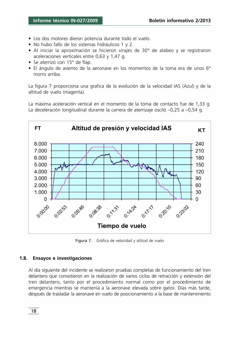
• Los dos motores dieron potencia durante todo el vuelo.• No hubo fallo de los sistemas hidráulicos 1 y 2.• Al iniciar la aproximación se hicieron virajes de 30° de alabeo y se registraron
aceleraciones verticales entre 0,63 y 1,47 g.• Se aterrizó con 15° de flap.• El ángulo de asiento de la aeronave en los momentos de la toma era de unos 6°
morro arriba.
La figura 7 proporciona una grafica de la evolución de la velocidad IAS (Azul) y de laaltitud de vuelo (magenta).
La máxima aceleración vertical en el momento de la toma de contacto fue de 1,33 g.La deceleración longitudinal durante la carrera de aterrizaje osciló –0,25 a –0,54 g.
Figura 7. Gráfica de velocidad y altitud de vuelo
1.8. Ensayos e investigaciones
Al día siguiente del incidente se realizaron pruebas completas de funcionamiento del trendelantero que consistieron en la realización de varios ciclos de retracción y extensión deltren delantero, tanto por el procedimiento normal como por el procedimiento deemergencia mientras se mantenía a la aeronave elevada sobre gatos. Días más tarde,después de trasladar la aeronave en vuelo de posicionamiento a la base de mantenimiento
Informe técnico IN-027/2009
19
Boletín informativo 2/2013
de Valencia, se repitieron las pruebas. En el hangar, en Valencia, las condiciones de pruebaeran las de avión en gatos, energizado con potencia eléctrica e hidráulica de equipos tierray con las compuertas dañadas de tren de morro desmontadas.
Los resultados fueron los siguientes:
1. Los ciclos de extensión y retracción de tren de morro y principales se hicieron contoda normalidad.
2. Las extensiones por el procedimiento alternativo se completaron con absolutanormalidad, cuando se tenía la precaución de situar la válvula seguidora mecánicade tren de morro-asociada a las compuertas de morro en su posición adecuada. Enlos casos en los que la posición de esa válvula no era adecuada se registrarontiempos de extensión de tren muy largos de hasta 225 segundos.
3. Repitiendo la retracción de tren por el sistema normal, es decir, subiendo la palancaselectora de tren, pero dejando abierta la trampilla-techo y cerrada la trampilla-suelo, el tren no subía y quedaban encendidas las tres luces rojas de tren inseguro.
4. En las condiciones del punto anterior 3, al cerrar la trampilla-techo comenzaban aretraerse las tres patas del avión, encendiéndose momentáneamente las luces decompuertas y apagándose todas las luces al blocar todas las patas arriba.
5. Repitiendo la retracción de tren por el sistema normal, es decir, subiendo la palancaselectora de tren, dejando abierta la trampilla-techo y abierta también latrampilla-suelo, el tren no subía y quedaban encendidas las tres luces rojas deinseguridad de tren.
6. En las condiciones del punto anterior 5, al cerrar la trampilla-techo comenzaba aretraerse la pata de morro permaneciendo extendidas las dos patas principales. Alterminar la retracción y blocarse la pata de morro arriba, su luz de indicación seapagaba; mientras permanecían encendidas las luces rojas correspondientes a laspatas principales. En el sistema de indicación alternativo de tren abajo y blocado seencendían las dos luces verdes correspondientes a las dos patas principales.
7. En los casos 4 y 6 entraba en funcionamiento el grupo motobomba PTU.
1.9. Información orgánica y de dirección
1.9.1. Procedimientos relacionados con la extensión del tren de aterrizaje
La compañía Denim Air tenía desarrollados y publicados los manuales de procedimientosde vuelo con listas de chequeo normales y de emergencia para uso de sus tripulaciones.
El prefacio de las listas de emergencia establece pautas generales que han de seguirsea la hora de trabajar con ellas:
• Las tripulaciones deben llevar a cabo los procedimientos correctamente, usando lasECL («Emergency Check List»), las habilidades combinadas de ambos pilotos y, sobretodo, el sano juicio.
20
Informe técnico IN-027/2009 Boletín informativo 2/2013
• Las ECL serán leídas en voz alta por el PNF (salvo que se especifique lo contrario),para permitir al PF estar al tanto del progreso en el procedimiento.
• Las acciones, selecciones o conmutaciones que no sean reversibles tendrán que sersiempre confirmadas por ambos pilotos antes de su ejecución.
• Al ocurrir una situación de emergencia, la naturaleza del fallo ha de ser claramenteestablecida por un piloto y confirmada por el otro.
• El PF inicia el procedimiento aplicable con la voz: «ACCIÓN».• Cada procedimiento ECL se iniciará declarando el PNF el nombre de la lista de
chequeo del procedimiento aplicable.• Cuando la lista de chequeo en particular haya sido completada el PNF deberá
anunciar «LISTA DE CHEQUEO COMPLETADA».
En el Manual de Operaciones de Denim Air, Parte B, Procedimientos de emergencia,«Pilot Incapacitation» se indica que siempre que el PM avise al PF de un desvío en elperfil de vuelo deseado, éste contestará «Checked Correcting»; si éste no responde, leavisará una vez más y si tampoco responde, el PM asumirá que el PF está incapacitadoy tomará los mandos del avión anunciando «My Control».
1.9.1.1. Prevuelo
La lista normal de chequeo de PRE-VUELO en su renglón 4 pide el chequeo de laposición de los controles alternativos de tren de aterrizaje:
Alternate landing gear controls .................................................... CHECKED
1.9.1.2. Fallo del sistema hidráulico #2. ECL 18
En el caso de fallo declarado del sistema hidráulico #2, que es el que alimenta el sistemade extensión y retracción normal de tren de aterrizaje, el procedimiento pide comprobarprimeramente si la cantidad de hidráulico es normal.
Con la utilización de la bomba hidráulica Stand-by y la PTU la presión se deberestablecer. En caso contrario el procedimiento se deriva al de extensión de trenalternativo.
Se advierte de que el procedimiento se debe completar antes del inicio de laaproximación, que el procedimiento puede llevar hasta 7 minutos y que, entre otros, seperderán los servicios de dirección de tren de morro y freno de aparcamiento.
Al mismo tiempo se hacen algunas consideraciones sobre el aterrizaje y se dice que nose debe utilizar la selección manual de PTU durante la aproximación.
Informe técnico IN-027/2009
21
Boletín informativo 2/2013
1.9.1.3. Funcionamiento defectuoso de los indicadores de tren de aterrizaje. ECL 24A
Cuando se sospeche un funcionamiento anómalo de las luces indicadoras de tren deaterrizaje ha de comprobarse la posición de tren abajo y blocado a través de losindicadores instalados dentro de la trampilla-suelo. El procedimiento termina con laacción de CERRAR la trampilla-suelo antes de proceder al aterrizaje normal o a laextensión alternativa de tren.
1.9.1.4. Luz de tren LDG INOP CAUTION LIGHT. ECL 24B
El procedimiento indica que ante la activación de esta luz, ha de bajarse el tren por elprocedimiento alternativo y se ha de aterrizar tan pronto como sea posible.
1.9.1.5. Extensión alternativa de tren de aterrizaje. ECL 25
En las consideraciones previas se advierte de que el procedimiento puede llevar hasta 7minutos en su ejecución y de que debe ser completado antes de entrar en laaproximación final. No se debe seleccionar la PTU en manual durante la aproximación.
Al tratar de los mandos de suelta de los blocajes de tren arriba se recuerda que lasfuerzas que haya de ejercerse sobre los tiradores pueden exceder las experimentadasdurante las prácticas de extensión en simulador.
El procedimiento completo se acompaña en el anexo A2. Se inicia con la apertura de latrampilla-techo y con la suelta del tren principal y comprobación de los indicadores delas compuertas y patas de tren izquierdo y derecho. A continuación pide la suelta deltren de morro y comprobaciones del estado de sus compuertas y blocaje. Tanto latrampilla-techo como la trampilla-suelo han de dejarse abiertas.
1.9.1.6. Aterrizaje con tren inseguro. ECL 26 («LANDING GEAR UNSAFE»)
En el caso de aterrizaje con tren de morro arriba y ambas patas principales desplegadas,se indica que los pasajeros deben sentarse en los asientos posteriores, que se debe bajarel morro antes de que se pierda la efectividad del timón de profundidad y que no sedebe exceder de un ángulo de asiento de 5° morro arriba en la recogida.
Como preparación para el aterrizaje se pide saltar los C/B (E5) de aviso de tren y C/B(B3/b9) del EGPWS, y el aviso para una posible evacuación. Se acompaña elprocedimiento completo en anexo A1.
22
Informe técnico IN-027/2009 Boletín informativo 2/2013
1.10. Información adicional
1.10.1. Listas de chequeo de emergencias relacionadas con el tren de aterrizajeen otros operadores y en el fabricante
En el manual QRH de la compañía Air Nostrum, explotador del vuelo y tambiénoperadora del mismo tipo de aeronave DHC8-315, página 11-2, se publica unprocedimiento «LANDING GEAR UNSAFE» que se refiere a la condición de luces de trende aterrizaje inseguro activas. Se adjunta en el anexo B1
En este caso, después de establecer la limitación de velocidad, se pide la confirmaciónde que la trampilla-techo está cerrada y también de que el interruptor de inhibición,INHIBIT SWITCH, está en posición normal. Si en esas condiciones las luces de treninseguro se apagan, el procedimiento permite la continuación normal del vuelo.
Las listas de chequeo utilizadas por el operador Denim Air normales y de emergencia yrelacionadas con este evento, y mencionadas en el punto anterior 1.9. «Informaciónorgánica y de dirección», eran congruentes con las listas de chequeo, normales y deemergencia aprobadas y recomendadas por el fabricante, de acuerdo con los datosrecopilados y provistos por éste.
2. ANÁLISIS
2.1. La secuencia de acciones sobre el sistema del tren de aterrizaje
Era el primer vuelo del día para la comandante pero no para el resto de la tripulaciónque ya había hecho la ruta inversa a la prevista para ese vuelo. Se decidió que en estetrayecto la comandante (CTE) actuaría como piloto a los mandos (PF) y el primer oficial(FO), como piloto supervisor (PM). El FO fue quien realizó la inspección exterior del aviónmientras la CTE efectuaba los procedimientos de cabina previos al vuelo (Lista dechequeo pre-vuelo).
Probablemente la trampilla-techo del sistema alternativo de extensión del tren principal«Landing Gear Alternate Release Door», ubicada en el techo de cabina, estabaparcialmente abierta cuando la tripulación llegó al avión, pero esto no fue detectado,ni por la CTE durante la inspección de cabina que realizó, ni posteriormente por ningunode los pilotos en cualquier momento antes del despegue; por tanto, en esa incorrectacondición el avión se fue al aire.
En estas circunstancias, la válvula bypass impide la presurización del sistema de tren deaterrizaje, por lo que este no se repliega cuando se sitúa en posición arriba la palancaselectora de tren.
Informe técnico IN-027/2009
23
Boletín informativo 2/2013
Cuando se actuó sobre la palanca del tren, después del despegue, la tripulación nodetectó nada anormal, probablemente muy concentrada en volar el avión y en seguir lasalida instrumental asignada en medio de una condiciones meteorológicas complicadascon numerosas nubes y tormenta cercanas.
Unos tres minutos después del despegue la tripulación descubrió que las tres luces rojasde indicación de tren inseguro. La tripulación no supo identificar la situación del tren ydiscutió durante varios minutos sobre ello y sobre la lista de emergencia que deberíanutilizar.
La CTE decidió que había que regresar a Barcelona y así se lo pidieron al ATC, quecomenzó a suministrar vectores radar hacia la pista 25R en un amplio circuito por laderecha, al noroeste del aeropuerto.
Solicitaron a la tripulante de cabina (TCP) la verificación visual directa de que el trenprincipal estaba abajo. También abrieron la «Landing Gear Alternate Extensión Door» yverificaron que se encendían las tres luces verdes al pulsar el interruptorcorrespondiente, pero no supieron determinar si estas luces verdes garantizaban el trenbajo y blocado o solo se trataba de un test, según sus propios comentarios. La trampillano se cerró después de comprobar las citadas luces, tal como indica el procedimientocorrespondiente (ECL 24 A). La válvula bypass del circuito hidráulico alternativo del trenprincipal permaneció por tanto activada.
Finalmente concluyeron que seguramente todas las patas estarían abajo y blocadas pero,no obstante, harían una extensión del tren por el sistema alternativo.
Con un rumbo paralelo a la pista unas 5 NM al NW de la misma, probablemente enesos momentos accionarían el interruptor de selección manual de PTU pero noobservarían ninguna consecuencia. Puesto que el sistema hidráulico #2 estabapresurizado y no había ninguna demanda de fluido, el grupo de motobomba PTU,equilibradas las presiones en sus dos extremos, no giraría.
El avión proseguía su curso NE en un largo tramo de viento en cola, mientras combatíanla emergencia y decidían realizar el procedimiento de extensión alternativa del tren deaterrizaje. Próximos al tramo de base del circuito (punto E de la Fig. 1), se inicia elprocedimiento alternativo de extensión, buscan el INHIBIT SWITCH y descubren latrampilla-techo abierta.
A partir de ese momento los tripulantes cierran momentáneamente la trampilla-techo yel tren en su conjunto aparentemente empieza el repliegue. La PTU, ante la demandade fluido de los martinetes, empieza a girar haciendo un ruido «estrepitoso yalarmante», según declararon los tripulantes. Puesto que el motor #2 seguía girandonormalmente y mantenía su presión de aceite, la única posibilidad de que entrara enfuncionamiento era que se hubiera seleccionado PTU en manual. Las compuertas de tren
24
Informe técnico IN-027/2009 Boletín informativo 2/2013
de morro se abrirían para dejar pasar las ruedas, encendiendo su correspondiente luzámbar, y la pata de morro se retraería completamente hasta blocar y apagar su luzámbar indicadora.
La alarma del ruido de la PTU hizo que se volviera a actuar sobre la trampilla-techo,abriéndola de nuevo y volviendo a activar el bypass del sistema hidráulico. Muyprobablemente, la trampilla suelo había quedado abierta y por tanto la válvula bypassdel sistema hidráulico alternativo o auxiliar permaneció cerrada. En esas condiciones elmartinete auxiliar no puede moverse actuando, entonces, como un blocaje hidráulico dela pata principal en cualquier posición en la que se encuentre. Por tanto las patasprincipales no se movieron en su posición abajo, ni llegarían a desblocarse sus blocajesde tren abajo.
Si los tripulantes no hubieran dejado abierta la trampilla-suelo y no hubieranseleccionado la PTU en manual, el tren de aterrizaje se habría retraído completamentesin que se hubiera escuchado ningún ruido anormal y se habrían apagado todas lasluces de tren, pudiendo proseguir su vuelo.
Interrumpido el procedimiento de extensión alternativa del tren por las anteriorescircunstancias, los tripulantes lo vuelven a retomar más tarde seleccionando la palancade tren abajo y tirando de la manilla de suelta del tren principal. Como ya se ha indicadolas patas principales se encontrarían ya abajo pero la suelta de blocajes condujo a quese abrieran las compuertas de tren principales. En la foto de la figura 2 se observa quela aeronave efectivamente había desplegado sus compuertas de tren principal.Seguidamente la CTE comprobó que, según las indicaciones en cabina, el tren de morrono estaba desplegado, ordenando al FO que tirara de la manilla correspondiente.
En la figura 2 se observa que las compuertas de tren de morro se abrieron lo queconfirma que el copiloto llegó a tirar de la manilla de suelta. Tal como advierte elprocedimiento, la fuerza aplicada tal vez no fuera suficiente y entonces no se llegó a soltar el blocaje de tren de morro arriba. En el sistema alternativo de posición detren se observarían dos luces verdes de tren principal abajo y blocado y la luzcorrespondiente al tren de morro apagada, hecho que confirmaría a la tripulación quedebían aterrizar sin tren de morro delantero.
Más tarde, cuando se procedió a retirar la aeronave de la pista, se volvió a tirar de esamanilla y se soltó el blocaje que dejó caer las ruedas de morro sin dificultad
A pesar de que el tren principal estaba correctamente desplegado el copiloto estuvoaccionando la bomba de mano auxiliar, acción únicamente útil para conseguir laextensión completa en caso de despliegue incompleto del tren principal.
En esos momentos la aeronave se encontraba en aproximación final, integrada en lostráficos del aeropuerto y preparándose para el inminente aterrizaje, pero sin haber

Informe técnico IN-027/2009
25
Boletín informativo 2/2013
preparado la aeronave según el procedimiento de aterrizaje de emergencia con el trende morro retraído. Se viraba con alabeo de menos de 30° pero registrando aceleracionesentre 0,63 y 1,47 g, lo que es indicativo de turbulencias.
El tren principal hacía contacto poco más de veinte minutos después del despegue conuna aceleración vertical de 1,33 g. El avión se paró totalmente 43 s después de la tomade contacto arrastrando el morro por el suelo durante lo últimos 12 segundos.
El agua en la pista contribuyó a reducir la fricción entre el morro y el asfalto y eliminóla posibilidad de que se generasen chispas.
2.2. La trampilla-techo en los procedimientos del fabricante y Demin-Air
Ninguno de los procedimientos con los que contaba el fabricante De Haviland y DenimAir consideraba que la posición de la trampilla-techo «Landing gear alternative releasedoor» pudiera ser la causa que impidiera la retracción del tren. Ante una indicación detren inseguro se guiaba a la tripulación a aplicar otros procedimientos de emergencia,inclusive la extensión alternativa del tren de aterrizaje. Si la tripulación hubiera contadocon un procedimiento que incluyera la comprobación de la posición de la trampillahabría podido advertir pronto la incongruencia de la posición de la misma, ycorrigiéndola, podría haber recogido el tren y continuado su vuelo con normalidad.
Se ha identificado un procedimiento llamado Tren de aterrizaje inseguro, adjuntado comoanexo B1, que contiene esta comprobación en un operador con amplia experiencia eneste tipo de aeronaves y por tanto parece razonable recomendar al fabricante DeHaviland-Bombardier y a Demin-Air que desarrollen un procedimiento similar.
2.3. La ejecución de los procedimientos por parte de la tripulación
Las grabaciones de CVR levantan fundadas dudas sobre la forma en la que se siguieronlos procedimientos. No hay referencias claras orales de los procedimientos que en cadamomento se están siguiendo, de la evaluación que se hace de la situación por cada unode los dos pilotos, de las acciones que se toman y de la finalización de losprocedimientos.
En la aplicación de los procedimientos se observan unas continuas interrupcionesdebidas a la conducción del vuelo, a las comunicaciones con ATC y a la atención a lasituación meteorológica. Son frecuentes también las desviaciones de atención por causasemocionales o secundarias y no se centran en la situación.
Comenzando con la preparación del vuelo, en la CL («Check List») normal de PRE-VUELO se pide a los pilotos la comprobación de los controles de extensión alternativa
26
Informe técnico IN-027/2009 Boletín informativo 2/2013
de tren. Una cuidadosa comprobación de la cabina al entrar en ella hubiera eliminadola causa desencadenante del incidente, la posición anormal de la trampilla-techo, totalo parcialmente abierta.
Una mayor atención a las condiciones de vuelo después de despegar y de seleccionartren arriba hubiera detectado enseguida que el tren no se replegaba; sin embargo latripulación tardó unos tres minutos en advertir la situación. El avión continuó acelerandoy ascendiendo, alcanzándose valores IAS de 199 kt superiores a las limitaciones de vuelocon tren fuera.
El procedimiento de fallo de sistema hidráulico #2 (ECL 18) no era necesario que seaplicara ó siguiera pues no se produjo tal fallo; el sistema hidráulico #2 no perdiópresión. Sin embargo, la activación de la PTU y la posición de su interruptor en cabina,en posición manual, evidencian que se manipuló sobre él. Se sospecha que el interruptorestuvo en posición manual durante 13 minutos desde su activación inicial hasta el findel aterrizaje, aún cuando las advertencias de los procedimientos establecen que no sedebe mantener el sistema PTU activado durante la aproximación. La limitación de tiempode funcionamiento proviene del calentamiento que un uso prolongado de la PTU puedeproducir en el líquido hidráulico. Como realmente la PTU no trabajaba, al estarinmovilizado el tren principal, se puede suponer que no llegaron a producirsecalentamientos anormales. La alarma que causó el ruido a la tripulación indica undesconocimiento del sistema.
El procedimiento 24A de comprobación alternativa de posición del tren insiste en que,cualquiera que sea el resultado de la comprobación, se cierre la trampilla-suelo antes deproceder adelante con otras acciones y procedimientos. Se sospecha que esta trampillase dejó abierta en buena lógica a la no retracción del tren principal al cerrarse latrampilla-techo. Abundando en esta conclusión, los resultados de las pruebas en hangarconfirman que el tren sube o no sube dependiendo de que la trampilla esté cerrada oabierta.
La lista de chequeo para la extensión alternativa del tren de aterrizaje advierte que elprocedimiento puede durar hasta 7 minutos, lo que se debe tomar comorecomendación para que se ejecute sosegadamente. El análisis de las grabaciones delCVR indica que a pesar de que el copiloto recordó esto al comandante, ocurrió ya muytarde y finalmente la tripulación no tuvo en cuanta esta recomendación.
Se recuerda que es posible que se tenga que hacer un esfuerzo considerable al tirar,para forzar el desblocaje y suelta del tren, con el objetivo de que inicie su caída porgravedad. De acuerdo con las pruebas realizadas y la condición del tren en el aterrizaje,se sospecha que el esfuerzo que se hizo durante el vuelo para soltar el tren de morrofue probablemente insuficiente.
Existiendo indicaciones suficientes de que las dos patas izquierda y derecha estabanabajo y blocadas la tripulación insistía, en cambio, en el uso de la bomba auxiliar, que
Informe técnico IN-027/2009
27
Boletín informativo 2/2013
no afecta al tren de morro lo cual confirma aquí también un cierto desconocimiento delsistema y del procedimiento.
El procedimiento recuerda también, repitiendo lo establecido en el ECL 18 – Fallo delsistema hidráulico #2, que no se debe seleccionar PTU en manual durante laaproximación.
En cuanto al aterrizaje con tren inseguro (ECL 26) el procedimiento no se siguió deforma explícita, aunque algunos de sus puntos pudieran haberse seguido de memoria.Así pues, no se tomaron las precauciones para reubicar a los pasajeros de la cabinaanterior en la posterior. De esa manera el peso sobre el morro se hubiera podido reduciren unos 200 kg. Tampoco se consiguió mantener actitudes de avión de menos de 5°de morro arriba, alcanzándose asientos de hasta 6° en la recogida y la toma.
Para la preparación del aterrizaje de emergencia se establece que se deben sacar losdisyuntores (C/B) E5 y B3/B9; de esa manera se anula la activación de la bocina de trende aterrizaje y los avisos de EGPWS, que van a producirse en el aterrizaje con un trenno completamente extendido. Como los C/B no se saltaron esos avisos acústicos seprodujeron, aumentando el estrés en los momentos de tensión del aterrizaje deemergencia.
2.4. Análisis de los factores humanos
Se ha podido comprobar que el avión no tenía ninguna avería que impidiera el normalfuncionamiento del tren de aterrizaje. Fueron actuaciones humanas incorrectas, poracción y por omisión, las que dieron lugar a que la trampilla-techo («Landing GearAlternate Release Door») estuviera indebidamente abierta, a que no se detectara suincorrecta posición en la preparación de la cabina o en cualquier otro momento antesdel despegue y, una vez en vuelo, a que no se supiera resolver con éxito la anormalidad.La actuación humana, en cuanto a los pilotos, está determinada por su competencia yhabilidad en aspectos, tanto técnicos como de los no-técnicos.
2.4.1. Competencia de los pilotos en aspectos técnicos
Ambos pilotos parecían tener un deficiente conocimiento del sistema alternativo deextensión del tren de aterrizaje, especialmente del efecto que ejerce la posición de lastrampillas «Landing Gear Alternate Release Door» y «Landing Gear Alternate ExtensionDoor». Además, por la manera que ejecutaron los procedimientos de emergenciacomentada anteriormente y por las conversaciones de cabina grabadas, puede deducirseque ninguno de ellos tenía un profundo conocimiento y soltura en el manejo del QRH.Estas conversaciones muestran ese desconocimiento, por ejemplo, cuando creenrecordar que hay una lista que se llama «unsafe», cuando dudan del significado de las
28
Informe técnico IN-027/2009 Boletín informativo 2/2013
luces verdes que observan bajo el «Landing Gear Alternate extension Door», cuandobuscan el modo de silenciar la bocina del tren o su empeño en bombear presión con lapalanca manual sin saber que no afectaría al tren de morro.
La CTE, al afirmar repetidamente que se habían quedado sin tren tras haber cerrado elFO la «Landing Gear Alternate Release Door» demostraba no entender correctamentesu función y, finalmente, su resignación a aterrizar sin tren de morro, dándolo porinevitable, demuestra un deficiente conocimiento general del sistema del tren y delprocedimiento de extensión alternativa.
Ninguno de los dos parecía conocer o recordar lo indicado en los procedimientos dondese resaltaba la importancia de tirar con contundencia de las manillas de extensión.
2.4.2. Competencia en habilidades no-técnicas, CRM
Una parte esencial de la responsabilidad del CTE es la gestión adecuada del tiempo,tanto para actuar con la diligencia requerida en unos casos como para saber encontrarla calma necesaria para pensar en otros casos, trazar los planes, hacer un briefing,distribuir la carga de trabajo, ejecutar los procedimientos sin errores, etc. En este casoel avión tenía combustible para ir y volver a San Sebastián y, por tanto, la oportunidadde entrar en espera y resolver adecuadamente la situación, pero la CTE insistiórepetidamente en que quería aterrizar cuanto antes.
Desde un principio, en tierra, se establecieron los roles básicos como tripulación por locual la CTE actuaría como piloto a los mandos (PF) y el FO como piloto que monitorizay lleva las comunicaciones (PM). Esta distribución de papeles comúnmente asume queen caso de emergencia el PF se concentrará en volar el avión mientras el PM se ocuparáde combatir la emergencia con la correspondiente lista de chequeo. Sin embargo, desdeque descubrieron el problema, la CTE se implicó en la lectura del QRH desatendiendoen cierto grado su papel de volar el avión. El FO se lo recordó a los 8:39 minutos devuelo, sin embargo ella pareció no oír y continuó revisando el QRH.
La ausencia de un eficaz reparto de tareas en cabina contribuyó al desorden y a laomisión de puntos en la ejecución de los procedimientos de emergencia y también auna pobre vigilancia que dio lugar a importantes desvíos de la velocidad y de la sendade vuelo requerida.
Debe señalarse también que la CTE tomó sus decisiones sin considerar las opiniones delFO. Tampoco actuó asumiendo que formaba parte de un equipo y que sus decisionesafectaban al resto, muy significativamente a la tripulante de cabina de pasajeros, decuyo trabajo dependía en buena medida la seguridad de los pasajeros.
No hay ningún motivo que haga pensar en la existencia de una mala relación personalentre ambos pilotos, al contrario; las largas conversaciones grabadas en el CVR antes
Informe técnico IN-027/2009
29
Boletín informativo 2/2013
del despegue, muchas de carácter personal, demuestran una buena relación y aficionescomunes entre ambos. Parece lógico pensar que hubiera en todo momento un clima deconfianza adecuado para la comunicación. Sin embargo, el curso de los acontecimientosy la revisión del CVR mostraron que la CTE tomó sus decisiones sin consultar con su FOy sin atender sus opiniones.
En parte la causa de la deficiente actuación como equipo se debe a que previamenteno se realizó un briefing en el que la CTE resaltara la necesidad de actuar como tal einvitara a la participación y a la comunicación abierta, especialmente cuando laseguridad se viera afectada.
Debe destacarse también el comportamiento poco asertivo del FO para transmitir a laCTE sus opiniones con la debida claridad e insistencia y asegurarse de que, comomínimo, eran tenidas en cuenta, tanto más cuanto más se veía afectada la seguridad.No solicitar abiertamente motor y al aire cuando la CTE manifestó finalmente su decisiónde aterrizar sin el tren de morro es muy revelador de esta falta de técnica CRM.
La defectuosa gestión como equipo y el ineficaz reparto de tareas dio lugar a una pobrevigilancia del vuelo y de la actuación del avión.
Durante dos minutos y medio la velocidad del avión superó la velocidad máximapermitida con el tren abajo (Vle de 173 kt), llegando hasta 197 kt. Durante la ejecucióndel procedimiento de extensión alternativa del tren, donde se indica que la velocidaddebe ser inferior a 140 kt, se mantuvo durante los casi cuatro minutos que emplearonen ello una velocidad siempre superior, alrededor de 150 kt.
También en aproximación, con el flap en posición 15°, la velocidad indicada cayó endos ocasiones por debajo de la de referencia (105 kt), llegando la segunda vez a 95 kt.En dos ocasiones, durante la aproximación, el PF se olvidó de descender cuando habíansido autorizados a ello y el PM tampoco lo detectó, y en varias ocasiones se olvidaronde cambiar de frecuencia radio después de haber sido transferidos.
2.4.3. Posible incapacitación velada de la CTE
Se reconoce generalmente la dificultad de identificar a tiempo la incapacitación de unpiloto en servicio, especialmente las veladas, las que no van acompañadas de síntomasevidentes como la pérdida de conocimiento, sin embargo éstas son más frecuentes ypotencialmente más peligrosas.
Es probable que la CTE estuviera sufriendo alguna forma de incapacitación velada quepudo afectar su actuación y el FO no fue capaz de detectarlo, a pesar de tener indiciossuficientes para sospechar de ello. Por ejemplo, la extraña obstinación de la CTE poraterrizar cuanto antes y su respuesta a estímulos importantes, como cuando el FO le
30
Informe técnico IN-027/2009 Boletín informativo 2/2013
indica que les están metiendo como número dos y quiere pedir tiempo para completarel procedimiento, ella contesta, «¡yo quiero aterrizar ya!». Durante la aproximación elavión sufrió en dos ocasiones una perdida involuntaria de velocidad que el FO anunciórepitiendo el aviso hasta 18 veces; especialmente en la primera de ellas la reacción dela CTE fue muy escasa durante varios segundos, pero el FO no cumplió el protocolocontemplado en su MO para detectar la posible incapacitación y tomar el control.
Por otra parte, las listas de chequeo y los avisos reglamentarios («call out») tienen unafunción adicional de interrelación entre ambos pilotos que permite detectarcomportamientos sospechosos de incapacitación. En este vuelo todas las listas normalesse hicieron por iniciativa del FO, incluso la «after take off» la «approach» y la «landing»que correspondía iniciar a la CTE, en su papel de PF; en ninguna de ellas se escuchaque la CTE responda a sus puntos. Tampoco se ha escuchado en el CVR ningún «callout» en relación con los modos seleccionados del piloto automático o FMS, o sobredesvíos de velocidad, salvo la señalada anteriormente. De este modo, por la falta deestandarización en el manejo de las listas y en el uso de los «call out» se perdió unaoportunidad adicional para detectar la posible incapacitación de la CTE.
Con el objetivo de paliar las deficiencias detectadas en los aspectos técnicos y de CRMse emiten dos recomendaciones de seguridad dirigidas al operador.
3. CONCLUSIÓN
3.1. Conclusiones
• La aeronave tenía un certificado de aeronavegabilidad en vigor y no se habíanregistrado defectos o averías en el sistema de tren de aterrizaje.
• Las listas de chequeo de los procedimientos utilizadas por el operador estabancopiadas y basadas en las suministradas por el fabricante.
• Inició el vuelo en Barcelona un día de tiempo tormentoso.• Después de despegar no subió el tren de aterrizaje al comandar su retracción.• Tras manipular diversos controles del sistema normal de tren de aterrizaje y del
sistema alternativo de extensión del tren de aterrizaje, el avión quedó configuradocon compuertas de tren abiertas, dos patas de tren de aterrizaje principal extendidasy blocadas, y pata de morro sin desplegar.
• Las luces indicadoras de tren del sistema alternativo mostraban las indicaciones detren principal blocado abajo y tren de morro inseguro y sin blocar.
• Se hizo una toma suave que contribuyó a minimizar los daños, que se circunscribierona las compuertas de tren de morro y abrasiones en el fuselaje en la zona de morro.
• Los 32 pasajeros y 3 tripulantes evacuaron la aeronave con normalidad con el apoyode los servicios de emergencia.
• No se encontraron defectos o causas técnicas que impidieran el normal funcionamientodel sistema normal y del sistema alternativo de operación del tren de aterrizaje.
Informe técnico IN-027/2009
31
Boletín informativo 2/2013
3.2. Causas
La causa del incidente fue la incorrecta manipulación del sistema de tren de aterrizajepor parte de la tripulación, que tanto por desconocimiento del mismo como pordeficiencias en el uso de los procedimientos disponibles, no supo identificar ni corregirla anormal configuración de la trampilla-techo del sistema alternativo de despliegue deltren.
4. RECOMENDACIONES DE SEGURIDAD
REC 90/12. Se recomienda al operador, DENIM AIR, que intensifique la formación delas tripulaciones sobre los procedimientos estándar operativos (SOP´S) engeneral, sobre el funcionamiento del sistema de extensión alternativa detren (incluyendo bomba manual, trampillas y su efecto en las válvulasbypass y auxiliar) y sobre el sistema PTU de transferencia de potenciahidráulica, incluyendo sus limitaciones de uso.
REC 91/12. Se recomienda al operador, DENIM AIR, que intensifique la formación delas tripulaciones en el ámbito de CRM, prestando especial atención a laimportancia que las competencias CRM tienen en la correcta ejecución delos procedimientos en general y en las situaciones de emergencia enparticular.
REC 92/12. Se recomienda al fabricante Bombardier Inc. (antiguo De Haviland) y aloperador DENIM AIR que definan e implementen un procedimientooperativo sobre la actuación de la tripulación en el caso de indicación detren inseguro, en el que se compruebe la posición de la trampilla techo«Landing Gear Alternate Release Door» y el «Inhibit Switch» del sistemahidráulico del tren de aterrizaje.
REC 93/12. Se recomienda a DENIM AIR que intensifique la formación de lastripulaciones para la aplicación de las listas de chequeo prevuelo y laverificación del estado de los instrumentos y elementos de control en lacabina de vuelo.


ANEXOS
Informe técnico IN-027/2009
33
Boletín informativo 2/2013


ANEXO A1Lista de chequeo utilizada por Denim Air.
Tren de aterrizaje inseguro («Landing gear unsafe»)
Informe técnico IN-027/2009
35
Boletín informativo 2/2013
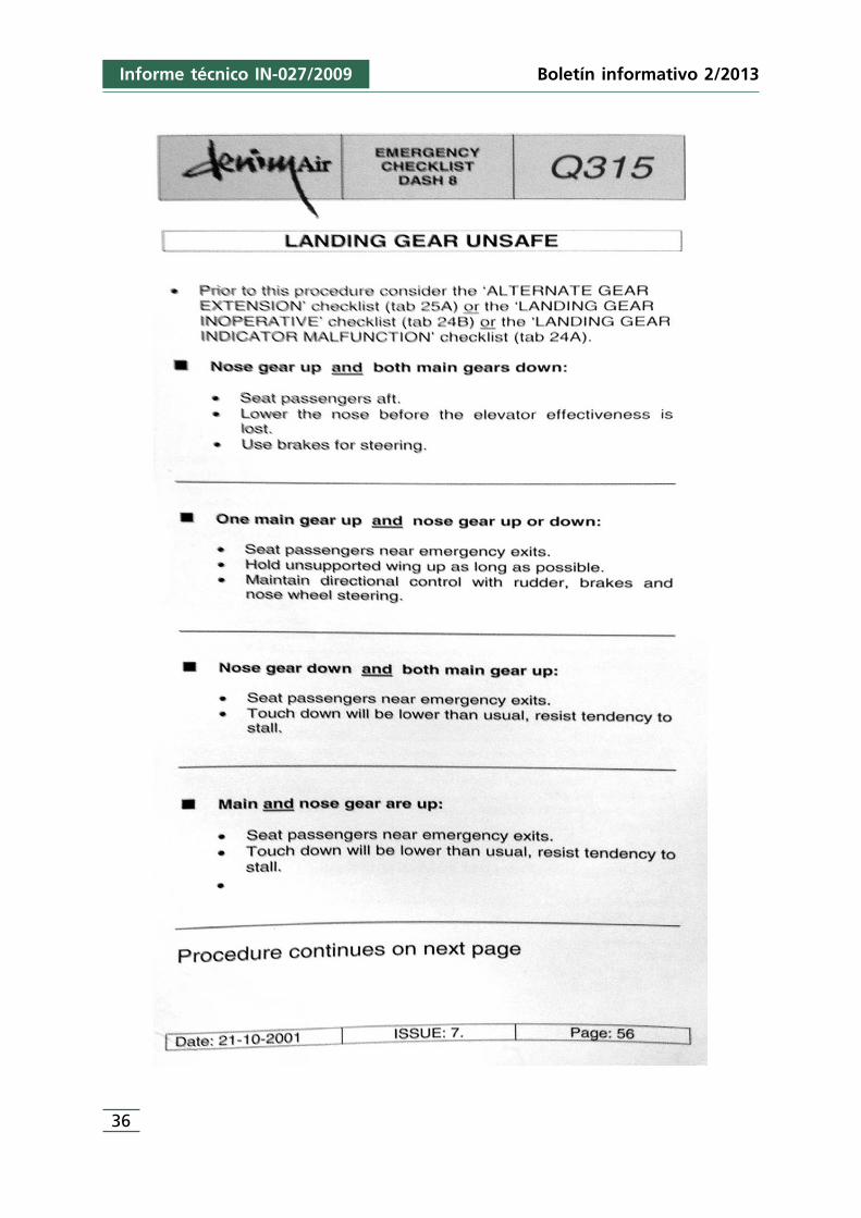
36
Informe técnico IN-027/2009 Boletín informativo 2/2013
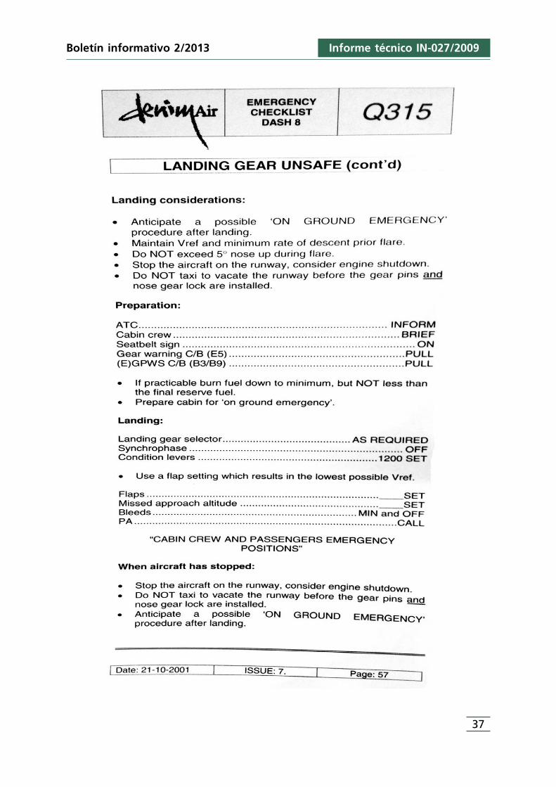
Informe técnico IN-027/2009
37
Boletín informativo 2/2013

ANEXO A2Lista de chequeo utilizada por Denim Air.
Extensión del tren de aterrizaje alternativo («Alternate gear extension»)
Informe técnico IN-027/2009
39
Boletín informativo 2/2013
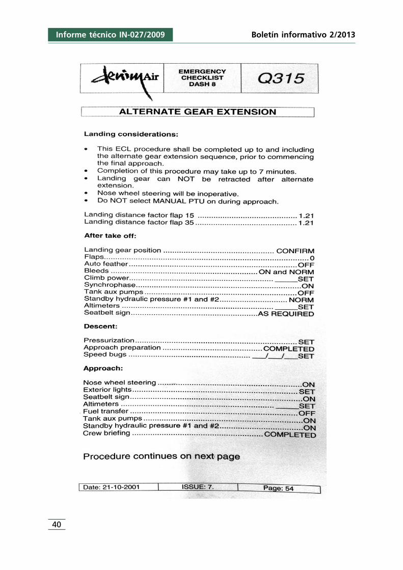
40
Informe técnico IN-027/2009 Boletín informativo 2/2013
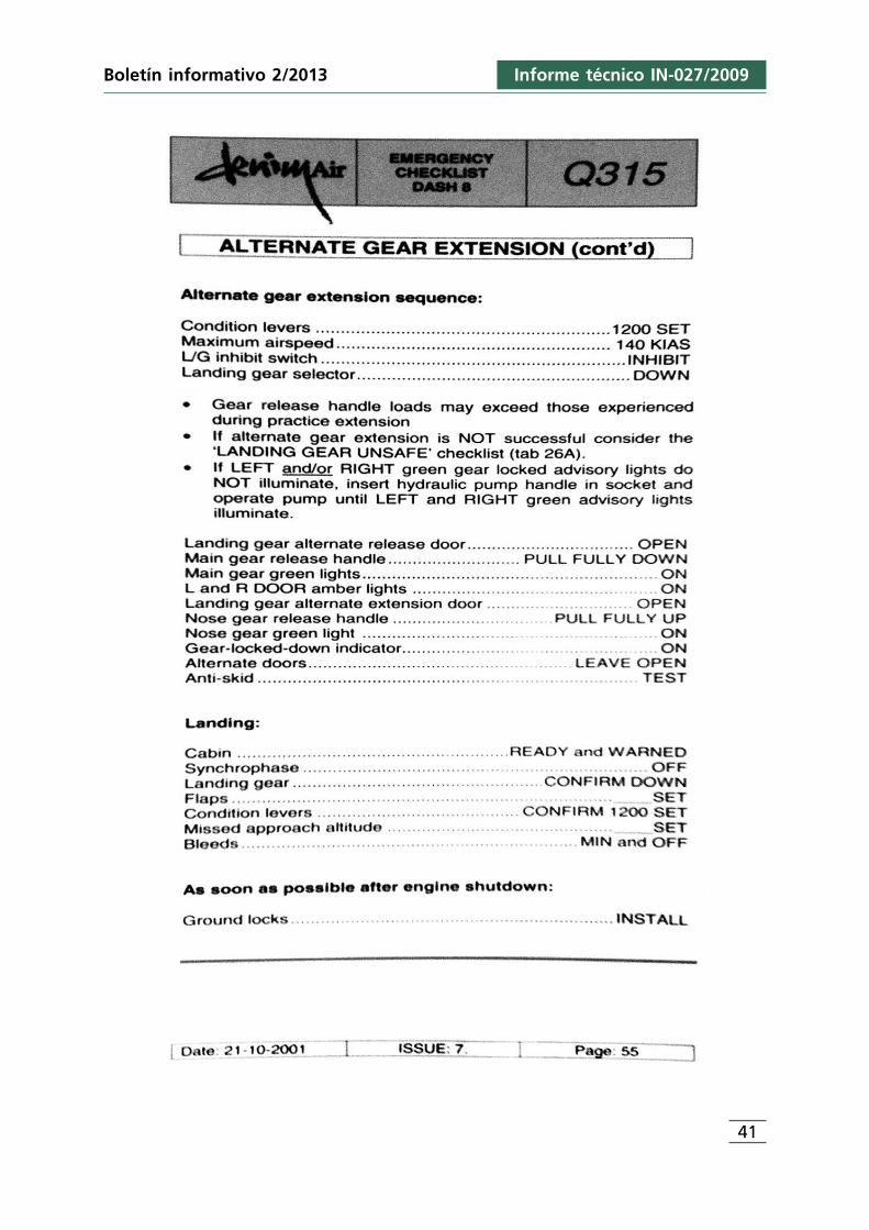
Informe técnico IN-027/2009
41
Boletín informativo 2/2013

ANEXO B1Lista de chequeo utilizada por Air Nostrum.
Tren de aterrizaje inseguro («Landing gear unsafe»)
Informe técnico IN-027/2009
43
Boletín informativo 2/2013
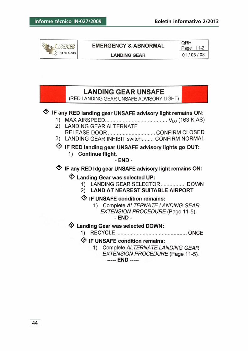
Boletín informativo 2/2013Informe técnico IN-027/2009
44
Boletín informativo 2/2013
45
Informe técnico IN-027/2009
ANEXO C1Comentarios del Dutch Safety Board
(Holanda)
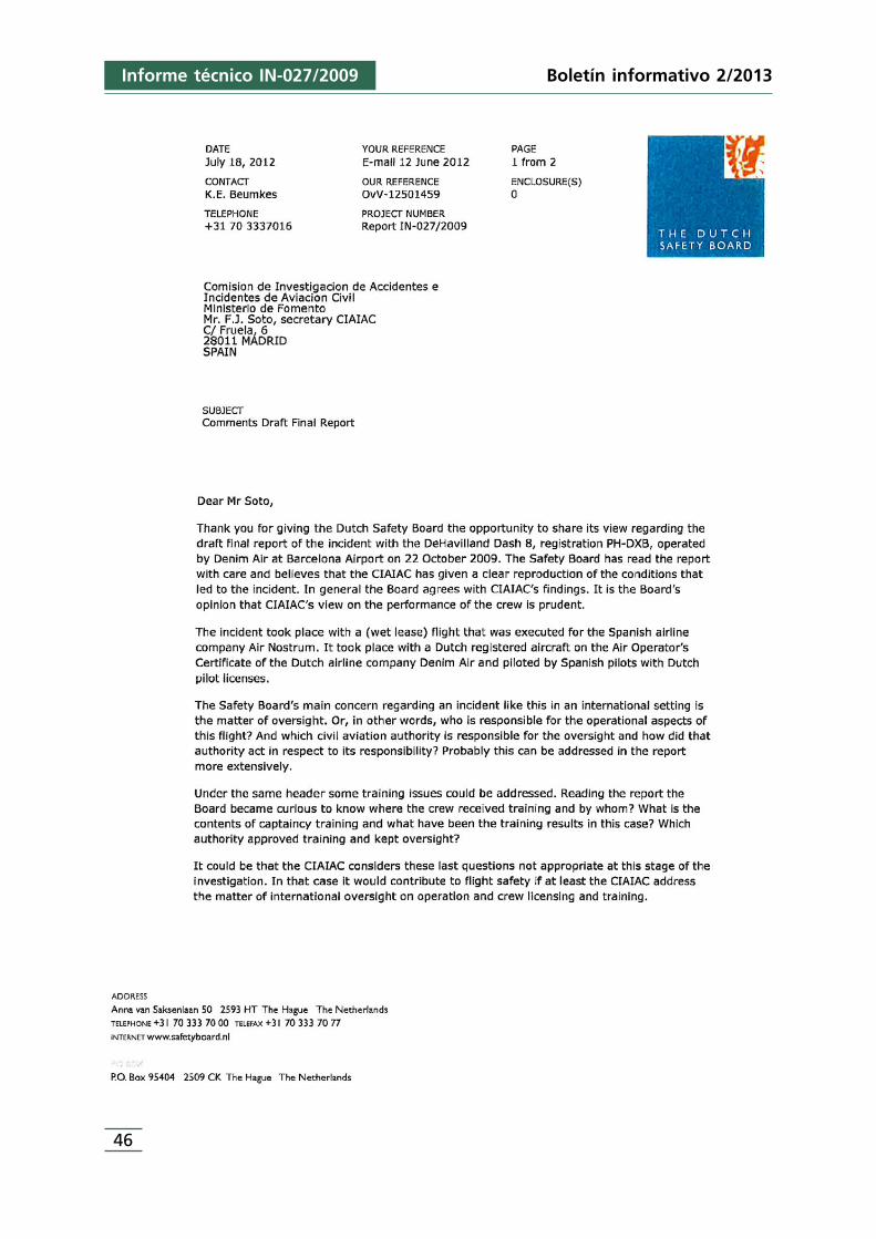
Boletín informativo 2/2013Informe técnico IN-027/2009
46
Boletín informativo 2/2013
47
Informe técnico IN-027/2009

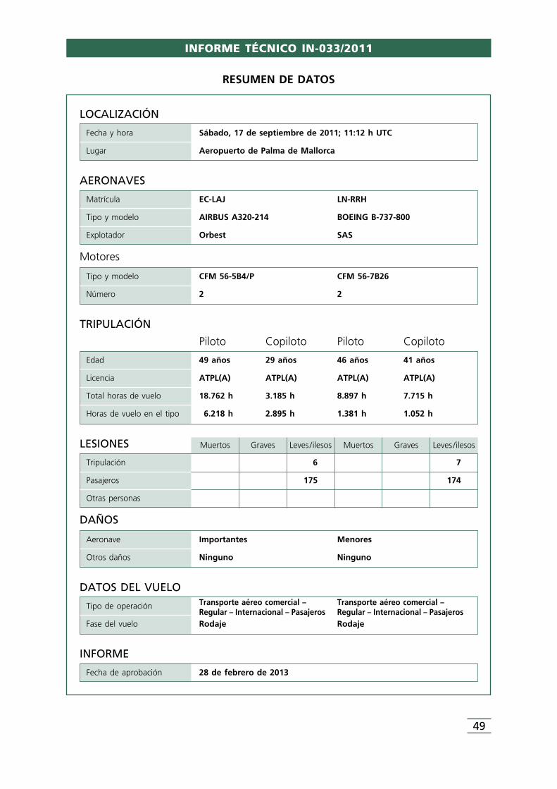
INFORME TÉCNICO IN-033/2011
49
LOCALIZACIÓN
Fecha y hora Sábado, 17 de septiembre de 2011; 11:12 h UTC
Lugar Aeropuerto de Palma de Mallorca
DATOS DEL VUELOTransporte aéreo comercial – Transporte aéreo comercial –Tipo de operaciónRegular – Internacional – Pasajeros Regular – Internacional – Pasajeros
Fase del vuelo Rodaje Rodaje
INFORME
Fecha de aprobación 28 de febrero de 2013
TRIPULACIÓN
Piloto Copiloto Piloto Copiloto
Edad 49 años 29 años 46 años 41 años
Licencia ATPL(A) ATPL(A) ATPL(A) ATPL(A)
Total horas de vuelo 18.762 h 3.185 h 8.897 h 7.715 h
Horas de vuelo en el tipo 6.218 h 2.895 h 1.381 h 1.052 h
AERONAVES
Matrícula EC-LAJ LN-RRH
Tipo y modelo AIRBUS A320-214 BOEING B-737-800
Explotador Orbest SAS
Motores
Tipo y modelo CFM 56-5B4/P CFM 56-7B26
Número 2 2
LESIONES Muertos Graves Leves /ilesos Muertos Graves Leves /ilesos
Tripulación 6 7
Pasajeros 175 174
Otras personas
DAÑOS
Aeronave Importantes Menores
Otros daños Ninguno Ninguno
RESUMEN DE DATOS
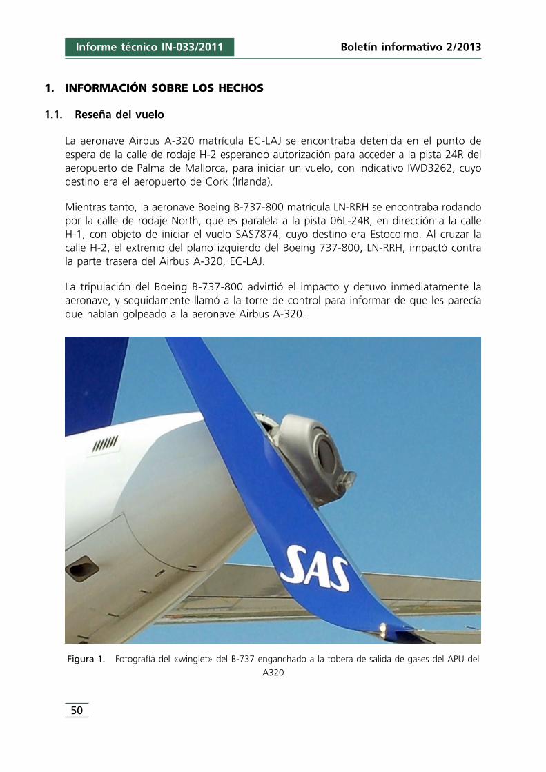
1. INFORMACIÓN SOBRE LOS HECHOS
1.1. Reseña del vuelo
La aeronave Airbus A-320 matrícula EC-LAJ se encontraba detenida en el punto deespera de la calle de rodaje H-2 esperando autorización para acceder a la pista 24R delaeropuerto de Palma de Mallorca, para iniciar un vuelo, con indicativo IWD3262, cuyodestino era el aeropuerto de Cork (Irlanda).
Mientras tanto, la aeronave Boeing B-737-800 matrícula LN-RRH se encontraba rodandopor la calle de rodaje North, que es paralela a la pista 06L-24R, en dirección a la calleH-1, con objeto de iniciar el vuelo SAS7874, cuyo destino era Estocolmo. Al cruzar lacalle H-2, el extremo del plano izquierdo del Boeing 737-800, LN-RRH, impactó contrala parte trasera del Airbus A-320, EC-LAJ.
La tripulación del Boeing B-737-800 advirtió el impacto y detuvo inmediatamente laaeronave, y seguidamente llamó a la torre de control para informar de que les parecíaque habían golpeado a la aeronave Airbus A-320.
Figura 1. Fotografía del «winglet» del B-737 enganchado a la tobera de salida de gases del APU del
A320
50
Informe técnico IN-033/2011 Boletín informativo 2/2013
El controlador envió un señalero para que comprobase si había habido impacto entreambas aeronaves, constatando que había habido contacto y que el «winglet» del planoizquierdo del B-737 estaba enganchado al cono de salida de gases del APU del A-320.
A fin de desenganchar las aeronaves se procedió a empujar el B-737 con un tractor.Después de ello ambas aeronaves retornaron por sus propios medios a la plataforma deestacionamiento para evaluar los daños que habían sufrido.
1.2. Lesiones de personas
No se produjo ninguna lesión personal.
1.3. Daños a la aeronave
La aeronave Airbus A320, matrícula EC-LAJ, tuvo daños en la parte trasera del fuselaje,que requirieron que se cambiase toda la sección que va desde la cuaderna 84 hasta elfinal del fuselaje, el conducto de escape de gases del APU y la estructura de raíles quesujeta esta parte, así como la reparación del mamparo cortafuegos de la cuaderna 84.
El Boeing B737, matrícula LN-RRH, tuvo daños en el borde de ataque y en algunas zonasdel recubrimiento del «winglet» del plano izquierdo.
1.4. Información personal
1.4.1. Aeronave EC-LAJ
Comandante
Edad: 49 años
Nacionalidad: Española
Licencia: ATPL (A), válida hasta 9/01/2013
Habilitaciones: • A320 válida hasta 27/07/2012• A330 válida hasta 27/06/2012• IR válida hasta 27/07/2012
Certificado médico clase 1: Válido hasta 18/10/2011
Horas totales de vuelo: 18.762 h
Horas de vuelo en tipo de aeronave: 6.218 h
Informe técnico IN-033/2011
51
Boletín informativo 2/2013
52
Informe técnico IN-033/2011 Boletín informativo 2/2013
Actividad desarrollada durante los 30 días previos: 89 h
Actividad desarrollada durante las 24 h previas: 6,3 h
Descanso previo al vuelo: 15:44 h
Hora de comienzo de la actividad: 06:45 h
Copiloto
Edad: 29 años
Nacionalidad: Española
Licencia: ATPL (A), válida hasta 29/03/2015
Habilitaciones: • A320 válida hasta 16/05/2012• IR válida hasta 16/05/2012
Certificado médico clase 1: Válido hasta 25/06/2012
Horas totales de vuelo: 3.185:43 h
Horas de vuelo en tipo de aeronave: 2.895:43 h
Actividad desarrollada durante los 30 días previos: 75:36 h
Actividad desarrollada durante las 24 h previas: 9:31 h
Descanso previo al vuelo: 15:45 h
Hora de comienzo de la actividad: 06:15 UTC
1.4.2. Aeronave LN-RRH
Comandante
Edad: 46 años
Nacionalidad: Sueca
Licencia: ATPL (A), válida hasta el 30/08/2013;
Habilitaciones: • B-737 300-900 válida hasta 31/05/2012• IR/ME/SP válidas hasta el 31/05/2012
Certificado médico clase 1: Válido hasta el 21/07/2012
Informe técnico IN-033/2011
53
Boletín informativo 2/2013
Competencia lingüística en inglés: Nivel 6
Horas totales de vuelo: 8.897 h
Horas de vuelo en tipo de aeronave: 1.381 h
Actividad desarrollada durante los 30 días previos: 57 h
Actividad desarrollada durante las 24 h previas: 4 h
Descanso previo al vuelo: 10:35 h
Hora de comienzo de la actividad: 04:35 UTC
Copiloto
Edad: 41 años
Nacionalidad: Noruega
Licencia: ATPL (A), válida hasta 31/03/2016
Habilitaciones: • B-737 300-900 válida hasta 31/05/2012• IR/ME válidas hasta el 31/05/2012
Certificado médico clase 1: Válido hasta el 10/11/2011
Competencia lingüística en inglés: Nivel 6
Horas totales de vuelo: 7.715 h
Horas de vuelo en tipo de aeronave: 1.052 h
Actividad desarrollada durante los 30 días previos: 47:46 h
Actividad desarrollada durante las 24 h previas: 4 h
Descanso previo al vuelo: 10:35 h
Hora de comienzo de la actividad: 04:35 UTC
1.5. Información de aeronave
1.5.1. Aeronave EC-LAJ
Marca: Airbus
Modelo: A320-214
Número de serie: 3889
54
Informe técnico IN-033/2011 Boletín informativo 2/2013
Año de construcción: 2009
Certificado de revisión de la aeronavegabilidad (ARC): Válido hasta 6/05/2012
Motores, número/marca y modelo: Dos (2)/CFM 56-5B4/P
Peso en vacío: 38.096 kg
Máximo peso al despegue: 77.000 kg
Dimensiones: • Envergadura: 34,09 m• Longitud: 37,57 m• Altura: 11,76 m• Base de ruedas: 7,59 m
Horas: 6.984:53 h
Ciclos: 2.610
1.5.2. Aeronave LN-RRH
Marca: Boeing
Modelo: B737-800 (con wing-lets)
Número de serie: 34546
Año de construcción: 2009
Certificado de revisión de la aeronavegabilidad (ARC): Válido hasta 2/06/2012
Motores, número/marca y modelo: Dos (2) CFM 56-7B26
Peso en vacío: 62.732 kg
Peso máximo al despegue: 78.999 kg
Dimensiones: • Envergadura: 35,79 m• Longitud: 42,1 m• Altura: 12,6 m• Base de ruedas: 5,70 m
Horas: 6.553,38 h
Ciclos: 3.633
1.6. Información meteorológica
Los METAR del aeropuerto de Palma de Mallorca correspondientes a las 10:30, 11:00 y11:30 h UTC del día del suceso son los siguientes:
Informe técnico IN-033/2011
55
Boletín informativo 2/2013
171030Z 22010KT 9999 FEW025 28/20 Q1017 NOSIG=
171100Z 22011KT 9999 FEW025 28/19 Q1016 NOSIG=
171130Z 22012KT 9999 FEW025 28/19 Q1016 NOSIG=
De ellos se desprende que a la hora en que tuvo lugar la colisión, alrededor de las11:15 h UTC, el viento era de dirección 220° y entre 11 y 12 kt de intensidad, lavisibilidad debía ser igual o mayor de 10 km, había nubes escasas a 2.500 ft, latemperatura sería de 28 °C, el punto de rocío de 19 °C y el QNH de 1.016 hPa.
1.7. Ayudas para la navegación
Las calles de rodaje ubicadas en el área en la que ocurrió el incidente, North, H-1, H-2y H-3 disponen de señales de eje de calle y de borde.
Los puntos de espera H-1, H-2 y H-3 de la pista 24R están señalizados mediante lasseñales y luces (barras de parada) normalizadas correspondientes. Las señalescorrespondían a la configuración B, indicada en el punto 5.2.10 de las Normas técnicasde diseño y operación de aeródromos de uso público, publicadas en el Real decreto862/2009, y en el punto 5.2.10 del Anexo 14, volumen I, de OACI.
1.8. Comunicaciones
1.8.1. Aeronaves EC-LAJ y LN-RRH
Las tripulaciones de ambas aeronaves establecieron contacto con control de rodadura(GMC) del aeropuerto de Palma para recabar las preceptivas autorizaciones de rodaje.
La tripulación del A-320 estableció contacto con control de rodadura Norte (GMC-N) enla frecuencia 121.9 MHz, a las 11:04:04 UTC, indicando que se encontraban en elestacionamiento 108 listos para rodar.
El controlador autorizó el rodaje e indicó las siguientes instrucciones: «ruede por E,punto de espera 24R», que fueron colacionadas por la tripulación.
A las 11:06:10 h la tripulación del Boeing B-737 llamó por radio a GMC-N solicitandoinstrucciones de rodaje. El controlador les indicó que rodasen vía F al punto de esperade la pista 24R, que fue correctamente colacionado por la tripulación.
A las 11:07:20 el controlador llamó a la aeronave A-320 para indicar a la tripulaciónque se mantuvieran a la escucha en la frecuencia 118.45 MHz, que corresponde a torrede control-salidas (TWR-DEP).
1 Este fragmento no ha podido ser interpretado.
56
Informe técnico IN-033/2011 Boletín informativo 2/2013
A las 11:08:03 h el controlador de GMC-N llamó a la tripulación del B-737 indicándolesque serían el número 1 por delante del avión de Monarch en la calle «North». Latripulación colacionó «número uno por delante del Monarch».
A las 11:09:51 h el controlador de GMC-N llamó de nuevo a la aeronave para indicar ala tripulación que se mantuvieran a la escucha en la frecuencia 118.45 MHz (TWR-DEP).
No hubo más comunicaciones hasta que a las 11:12:46 h la tripulación llamó a TWR-DEP para informar de que creían que habían golpeado la cola de otra aeronave. Elcontrolador pidió que repitiesen la información, a lo que la tripulación respondió quehabían golpeado la cola del Airbus español que estaba en el punto de espera. Elcontrolador respondió que mantuvieran la posición y que eran el número cuatro pordetrás del avión español, respondiendo la tripulación que mantendrían su posición.
Inmediatamente después, concretamente a las 11:13:24 h, la tripulación del Airbus A-320 llamó a TWR-DEP para informar que estaban en H-2 y que habían notado un fuertegolpe en la parte trasera, en la cola, y pedían al controlador si podía confirmarles sialguien les había golpeado.
El controlador respondió «eehh, el BER y el SAS... habían topado pero no pensé que lehabían golpeado, eh ¿puede ser que haya sido el SAS?».
La tripulación del A-320 respondió que habían notado un movimiento fuerte, pero queno sabían si había habido contacto o había sido el rebufo.
Entonces el controlador pidió a la tripulación del B-737 de SAS que informase cuál erasu posición, respondiendo éstos que estaban casi en «A...»1 pero que pensaban quehabían golpeado la cola del avión que estaba a su izquierda, un Orbest.
El controlador respondió que había copiado la información y le solicitó que le dijesenen qué posición estaba el avión en ese momento, respondiendo la tripulación del B-737que estaban en H-2 justo detrás del Airbus.
El controlador informó a las tripulaciones de ambas aeronaves que enviaba a un señaleropara que comprobase la situación.
1.8.2. Otras aeronaves
La aeronave con distintivo de llamada TOM9FT fue autorizada a las 10:59:39 a rodar alpunto de espera de la pista 24R, a través de la puerta E.
Informe técnico IN-033/2011
57
Boletín informativo 2/2013
Segundos después el controlador autorizó el rodaje de la aeronave con distintivo dellamada TOM19K hasta el punto de espera de la pista 24R, a través de la puerta G.
Alrededor de las 11:04:00 el controlador de rodadura indicó a ambas aeronaves quecontactasen con TWR-DEP en la frecuencia 118.45 MHz.
A las 11:07:40 el controlador llamó a la aeronave MON875 para indicar a su tripulaciónque eran número 2 por detrás del SAS. Esta aeronave fue transferida a TWR-DEP a las11:09:51.
A las 11:08:06 el controlador de TWR-DEP llamó a la aeronave TOM19K para autorizarla entrada en pista y el alineamiento de esta aeronave. El despegue fue autorizado a las11:10:45 y se produjo efectivamente a las 11:12:00.
A las 11:10:59 el controlador autorizó a la aeronave TOM9FT para que despegara detrásdel TOM19K. El despegue de esta aeronave se produjo a las 11:16:10, después dehaberse producido el impacto entre las otras dos aeronaves.
Ninguna de estas aeronaves fue autorizada por la torre de control a utilizar la calle H-1,ni se les asignó un punto de espera concreto.
1.9. Información de aeródromo
1.9.1. Configuración del campo de vuelos
El aeropuerto de Palma de Mallorca tiene categoría OACI «4-E».
Dispone de dos pistas de vuelo paralelas, denominadas 06R-24L y 06L-24R, siendo enla zona de acceso a la cabecera 24R en la que ocurrió el suceso.
La pista 06L-24R tiene una calle de rodaje paralela denominada «North». La separaciónentre sus ejes es de 200 m. El acceso desde la calle de rodaje al umbral 24R se realizaa través de tres calles de conexión denominadas H-1, H-2 y H-3. El umbral 24R estádesplazado 70 m.
Esta calle de rodaje, «North», tiene una anchura de 23 m y cuenta con señales de ejey de borde de calle.
En el plano de aeródromo para movimientos en tierra-OACI, configuración oeste, «AD2-LEPA GMC 1.2», contenido en el AIP España, figuran identificadas mediante círculoslas zonas calientes («hot spot»), desde el punto de vista de rodaje. En la calle de rodaje«North» solamente hay una zona identificada, que está en el cruce de las calles «North»y «Link», que queda alejada de la zona en la que tuvo lugar el incidente.
2 Según letra de clave (clave de referencia de aeródromo), tabla 1-1 del Anexo 14 «Aeródromos», volumen I «Diseñoy operaciones de aeródromos».
58
Informe técnico IN-033/2011 Boletín informativo 2/2013
La torre de control del aeropuerto de Palma de Mallorca está ubicada en las cercaníasdel edificio terminal, en su lado aire. Su situación es tal que podría decirse quegeográficamente está situada en el centro del aeropuerto. La distancia en línea rectaque hay desde la torre hasta la zona en la que ocurrió el incidente es de unos 1.700 m.Debido a ello, desde el fanal es difícil discernir la posición de las aeronavesen la zona de espera de la pista 24R.
En el primer semestre del año 2007 se llevó a cabo una identificación de peligrosfísicos en el aeropuerto, mediante la que se detectó que las aeronaves que seencontraran detenidas en los puntos de espera H-1 y H-2 vulnerarían la superficie(limitadora de obstáculos) de aproximación a la pista 24R (el punto de espera H-3 nosuponía afección a las superficies limitadoras de obstáculos). Dicho peligro se clasificócomo «tolerable».
Si bien los peligros así clasificados son tolerables en ese estado, es recomendable laadopción de medidas de mitigación, a fin de reducir el nivel de riesgo hasta el más bajoque sea razonablemente posible, aunque dado su nivel de riesgo no es necesario quelas acciones correctoras sean ejecutadas de forma inmediata.
Por este motivo, se decidió que debían retranquearse los puntos de espera H-1 y H-2una distancia de 71 m y 59,2 m, respectivamente, para que no se produjeranperforaciones en la superficie de aproximación (véase figura 2), aunque no se fijó ningúnplazo para ello. Como consecuencia del retranqueo, se reduciría la distancia entre dichospuntos de espera y el eje de la calle de rodaje «North» hasta un nivel «inaceptable».
En el primer semestre del año 2011 se decidió acometer dicho retranqueo. En el mesde junio se realizó un estudio de gestión de riesgos en el que se evaluó la operativa ylas posibles afecciones existentes (chorro de motores, distancias de seguridad, etc.)derivadas de las nuevas ubicaciones de los puntos de espera.
Dicho estudio fue analizado y aprobado en una sesión de identificación de riesgoscelebrada el 16/06/2011, en la que intervinieron representantes de la torre de control,del centro de control y del aeropuerto (campo de vuelo, seguridad operacional yejecución de la infraestructura).
Este estudio estableció las siguientes conclusiones:
• La operativa en los puntos de espera H-1, H-2 y H-3 debe quedar restringida por eltamaño de aeronaves Cat.2 D, E y E, respectivamente.
• El acceso al punto de espera H-1 deberá efectuarse cuando en H-2 no haya aeronaveposicionada.
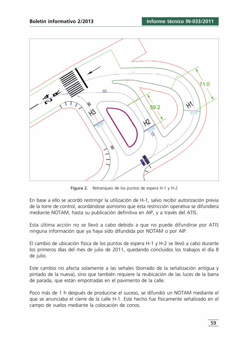
Informe técnico IN-033/2011
59
Boletín informativo 2/2013
Figura 2. Retranqueo de los puntos de espera H-1 y H-2
En base a ello se acordó restringir la utilización de H-1, salvo recibir autorización previade la torre de control, acordándose asimismo que esta restricción operativa se difundieramediante NOTAM, hasta su publicación definitiva en AIP, y a través del ATIS.
Esta última acción no se llevó a cabo debido a que no puede difundirse por ATISninguna información que ya haya sido difundida por NOTAM o por AIP.
El cambio de ubicación física de los puntos de espera H-1 y H-2 se llevó a cabo durantelos primeros días del mes de julio de 2011, quedando concluidos los trabajos el día 8de julio.
Este cambio no afecta solamente a las señales (borrado de la señalización antigua ypintado de la nueva), sino que también requiere la reubicación de las luces de la barrade parada, que están empotradas en el pavimento de la calle.
Poco más de 1 h después de producirse el suceso, se difundió un NOTAM mediante elque se anunciaba el cierre de la calle H-1. Este hecho fue físicamente señalizado en elcampo de vuelos mediante la colocación de conos.
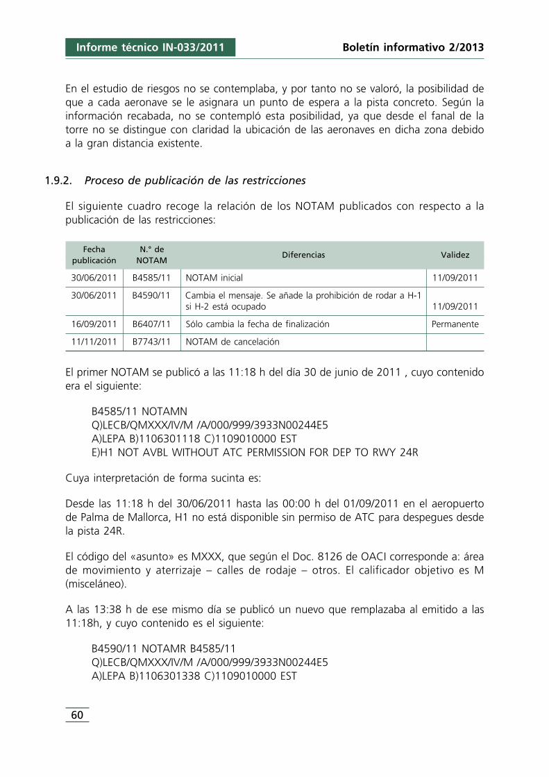
60
Informe técnico IN-033/2011 Boletín informativo 2/2013
En el estudio de riesgos no se contemplaba, y por tanto no se valoró, la posibilidad deque a cada aeronave se le asignara un punto de espera a la pista concreto. Según lainformación recabada, no se contempló esta posibilidad, ya que desde el fanal de latorre no se distingue con claridad la ubicación de las aeronaves en dicha zona debidoa la gran distancia existente.
1.9.2. Proceso de publicación de las restricciones
El siguiente cuadro recoge la relación de los NOTAM publicados con respecto a lapublicación de las restricciones:
Fecha N.° depublicación NOTAM
Diferencias Validez
30/06/2011 B4585/11 NOTAM inicial 11/09/2011
30/06/2011 B4590/11 Cambia el mensaje. Se añade la prohibición de rodar a H-1si H-2 está ocupado 11/09/2011
16/09/2011 B6407/11 Sólo cambia la fecha de finalización Permanente
11/11/2011 B7743/11 NOTAM de cancelación
El primer NOTAM se publicó a las 11:18 h del día 30 de junio de 2011 , cuyo contenidoera el siguiente:
B4585/11 NOTAMNQ)LECB/QMXXX/IV/M /A/000/999/3933N00244E5A)LEPA B)1106301118 C)1109010000 ESTE)H1 NOT AVBL WITHOUT ATC PERMISSION FOR DEP TO RWY 24R
Cuya interpretación de forma sucinta es:
Desde las 11:18 h del 30/06/2011 hasta las 00:00 h del 01/09/2011 en el aeropuertode Palma de Mallorca, H1 no está disponible sin permiso de ATC para despegues desdela pista 24R.
El código del «asunto» es MXXX, que según el Doc. 8126 de OACI corresponde a: áreade movimiento y aterrizaje – calles de rodaje – otros. El calificador objetivo es M(misceláneo).
A las 13:38 h de ese mismo día se publicó un nuevo que remplazaba al emitido a las11:18h, y cuyo contenido es el siguiente:
B4590/11 NOTAMR B4585/11Q)LECB/QMXXX/IV/M /A/000/999/3933N00244E5A)LEPA B)1106301338 C)1109010000 EST
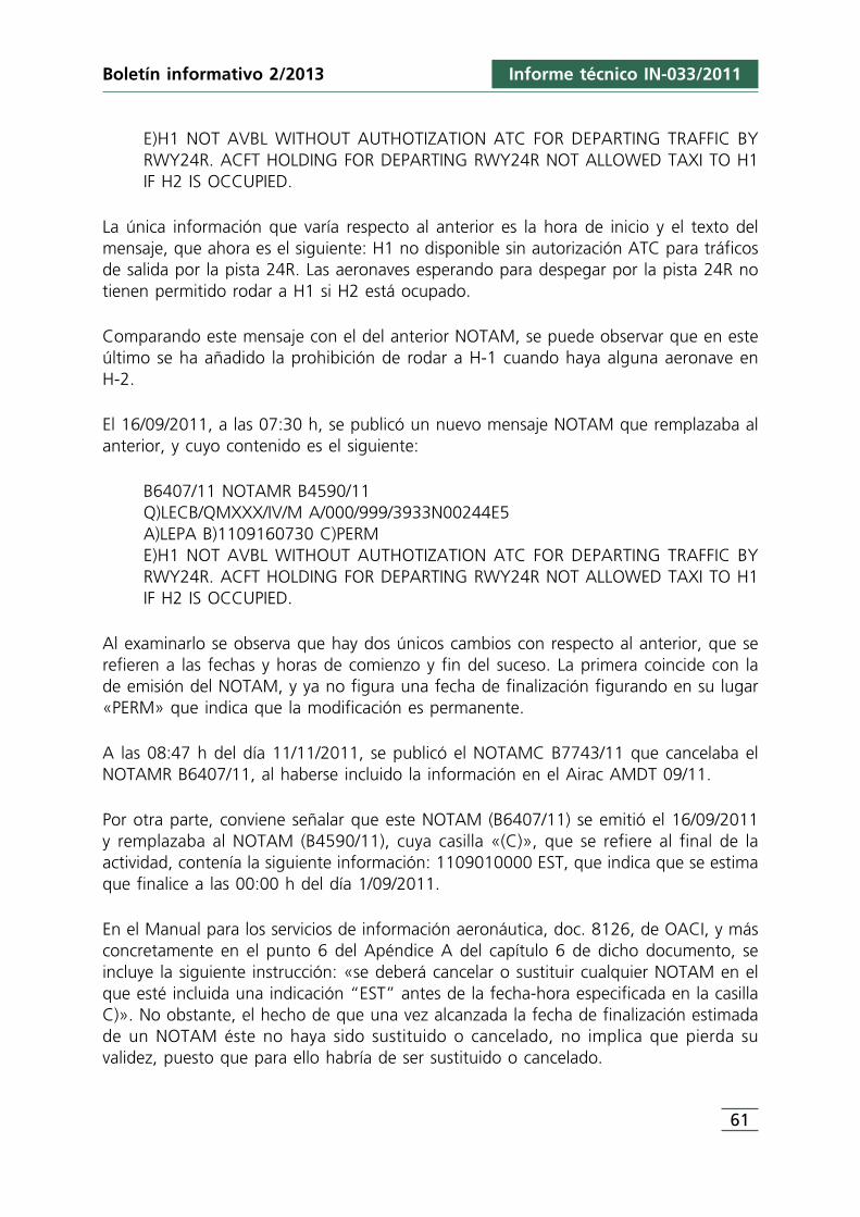
Informe técnico IN-033/2011
61
Boletín informativo 2/2013
E)H1 NOT AVBL WITHOUT AUTHOTIZATION ATC FOR DEPARTING TRAFFIC BYRWY24R. ACFT HOLDING FOR DEPARTING RWY24R NOT ALLOWED TAXI TO H1IF H2 IS OCCUPIED.
La única información que varía respecto al anterior es la hora de inicio y el texto delmensaje, que ahora es el siguiente: H1 no disponible sin autorización ATC para tráficosde salida por la pista 24R. Las aeronaves esperando para despegar por la pista 24R notienen permitido rodar a H1 si H2 está ocupado.
Comparando este mensaje con el del anterior NOTAM, se puede observar que en esteúltimo se ha añadido la prohibición de rodar a H-1 cuando haya alguna aeronave enH-2.
El 16/09/2011, a las 07:30 h, se publicó un nuevo mensaje NOTAM que remplazaba alanterior, y cuyo contenido es el siguiente:
B6407/11 NOTAMR B4590/11Q)LECB/QMXXX/IV/M A/000/999/3933N00244E5A)LEPA B)1109160730 C)PERME)H1 NOT AVBL WITHOUT AUTHOTIZATION ATC FOR DEPARTING TRAFFIC BYRWY24R. ACFT HOLDING FOR DEPARTING RWY24R NOT ALLOWED TAXI TO H1IF H2 IS OCCUPIED.
Al examinarlo se observa que hay dos únicos cambios con respecto al anterior, que serefieren a las fechas y horas de comienzo y fin del suceso. La primera coincide con lade emisión del NOTAM, y ya no figura una fecha de finalización figurando en su lugar«PERM» que indica que la modificación es permanente.
A las 08:47 h del día 11/11/2011, se publicó el NOTAMC B7743/11 que cancelaba elNOTAMR B6407/11, al haberse incluido la información en el Airac AMDT 09/11.
Por otra parte, conviene señalar que este NOTAM (B6407/11) se emitió el 16/09/2011y remplazaba al NOTAM (B4590/11), cuya casilla «(C)», que se refiere al final de laactividad, contenía la siguiente información: 1109010000 EST, que indica que se estimaque finalice a las 00:00 h del día 1/09/2011.
En el Manual para los servicios de información aeronáutica, doc. 8126, de OACI, y másconcretamente en el punto 6 del Apéndice A del capítulo 6 de dicho documento, seincluye la siguiente instrucción: «se deberá cancelar o sustituir cualquier NOTAM en elque esté incluida una indicación “EST” antes de la fecha-hora especificada en la casillaC)». No obstante, el hecho de que una vez alcanzada la fecha de finalización estimadade un NOTAM éste no haya sido sustituido o cancelado, no implica que pierda suvalidez, puesto que para ello habría de ser sustituido o cancelado.
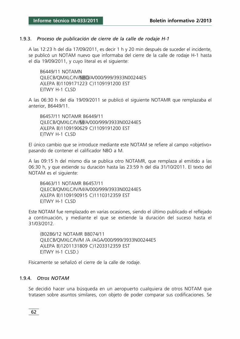
62
Informe técnico IN-033/2011 Boletín informativo 2/2013
1.9.3. Proceso de publicación de cierre de la calle de rodaje H-1
A las 12:23 h del día 17/09/2011, es decir 1 h y 20 min después de suceder el incidente,se publicó un NOTAM nuevo que informaba del cierre de la calle de rodaje H-1 hastael día 19/09/2011, y cuyo literal es el siguiente:
B6449/11 NOTAMNQ)LECB/QMXLC/IV/NBO/A/000/999/3933N00244E5A)LEPA B)1109171223 C)1109191200 ESTE)TWY H-1 CLSD
A las 06:30 h del día 19/09/2011 se publicó el siguiente NOTAMR que remplazaba elanterior, B6449/11.
B6457/11 NOTAMR B6449/11Q)LECB/QMXLC/IV/M/A/000/999/3933N00244E5A)LEPA B)1109190629 C)1109191200 ESTE)TWY H-1 CLSD
El único cambio que se introduce mediante este NOTAM se refiere al campo «objetivo»pasando de contener el calificador NBO a M.
A las 09:15 h del mismo día se publica otro NOTAMR, que remplaza al emitido a las06:30 h, y que extiende su duración hasta las 23:59 h del día 31/10/2011. El texto delNOTAM es el siguiente:
B6463/11 NOTAMR B6457/11Q)LECB/QMXLC/IV/M/A/000/999/3933N00244E5A)LEPA B)1109190915 C)1110312359 ESTE)TWY H-1 CLSD
Este NOTAM fue remplazado en varias ocasiones, siendo el último publicado el reflejadoa continuación, y mediante el que se extiende la duración del suceso hasta el31/03/2012.
(B0286/12 NOTAMR B8074/11Q)LECB/QMXLC/IV/M /A /AGA/000/999/3933N00244E5A)LEPA B)1201131809 C)1203312359 ESTE)TWY H-1 CLSD.)
Físicamente se señalizó el cierre de la calle de rodaje.
1.9.4. Otros NOTAM
Se decidió hacer una búsqueda en un aeropuerto cualquiera de otros NOTAM quetratasen sobre asuntos similares, con objeto de poder comparar sus codificaciones. Se
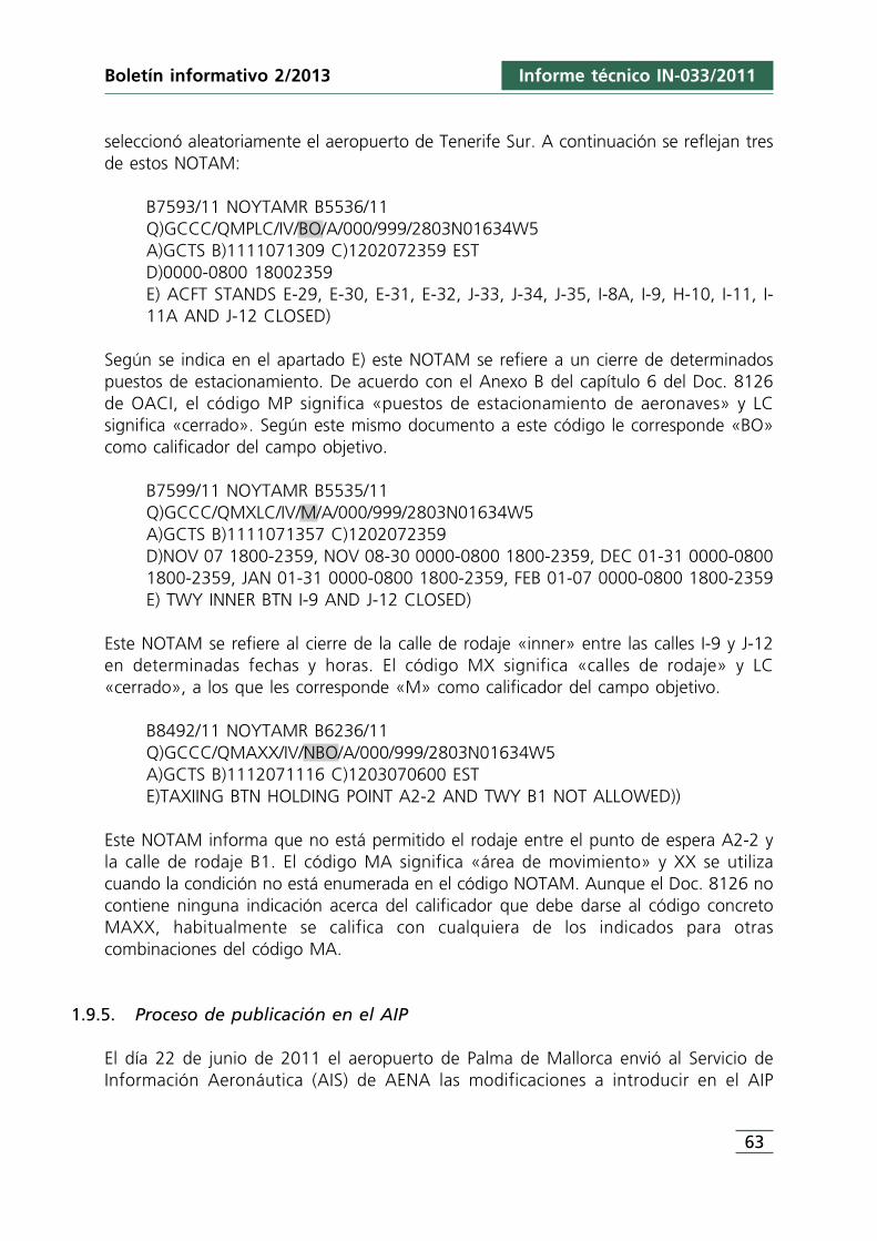
Informe técnico IN-033/2011
63
Boletín informativo 2/2013
seleccionó aleatoriamente el aeropuerto de Tenerife Sur. A continuación se reflejan tresde estos NOTAM:
B7593/11 NOYTAMR B5536/11Q)GCCC/QMPLC/IV/BO/A/000/999/2803N01634W5A)GCTS B)1111071309 C)1202072359 ESTD)0000-0800 18002359E) ACFT STANDS E-29, E-30, E-31, E-32, J-33, J-34, J-35, I-8A, I-9, H-10, I-11, I-11A AND J-12 CLOSED)
Según se indica en el apartado E) este NOTAM se refiere a un cierre de determinadospuestos de estacionamiento. De acuerdo con el Anexo B del capítulo 6 del Doc. 8126de OACI, el código MP significa «puestos de estacionamiento de aeronaves» y LCsignifica «cerrado». Según este mismo documento a este código le corresponde «BO»como calificador del campo objetivo.
B7599/11 NOYTAMR B5535/11Q)GCCC/QMXLC/IV/M/A/000/999/2803N01634W5A)GCTS B)1111071357 C)1202072359D)NOV 07 1800-2359, NOV 08-30 0000-0800 1800-2359, DEC 01-31 0000-08001800-2359, JAN 01-31 0000-0800 1800-2359, FEB 01-07 0000-0800 1800-2359E) TWY INNER BTN I-9 AND J-12 CLOSED)
Este NOTAM se refiere al cierre de la calle de rodaje «inner» entre las calles I-9 y J-12en determinadas fechas y horas. El código MX significa «calles de rodaje» y LC«cerrado», a los que les corresponde «M» como calificador del campo objetivo.
B8492/11 NOYTAMR B6236/11Q)GCCC/QMAXX/IV/NBO/A/000/999/2803N01634W5A)GCTS B)1112071116 C)1203070600 ESTE)TAXIING BTN HOLDING POINT A2-2 AND TWY B1 NOT ALLOWED))
Este NOTAM informa que no está permitido el rodaje entre el punto de espera A2-2 yla calle de rodaje B1. El código MA significa «área de movimiento» y XX se utilizacuando la condición no está enumerada en el código NOTAM. Aunque el Doc. 8126 nocontiene ninguna indicación acerca del calificador que debe darse al código concretoMAXX, habitualmente se califica con cualquiera de los indicados para otrascombinaciones del código MA.
1.9.5. Proceso de publicación en el AIP
El día 22 de junio de 2011 el aeropuerto de Palma de Mallorca envió al Servicio deInformación Aeronáutica (AIS) de AENA las modificaciones a introducir en el AIP
64
Informe técnico IN-033/2011 Boletín informativo 2/2013
referentes a dicho aeropuerto, entre las que se encontraban las restricciones de rodajepara salidas por la pista 24R.
Toda la información que recibe el Servicio AIS se somete a un proceso de comprobación,tratamiento y preparación. Una vez completado éste, se procede a enviar la informacióna imprenta para su publicación. Todo este proceso puede ocupar entre uno y dos meses.
Esta información se incluyó concretamente en la enmienda AIP AMDT 09/11 publicadaen el ciclo AIRAC del 8 de septiembre de 2011, cuya fecha de entrada en vigor era el20 de octubre de 2011.
El sistema AIRAC se basa en unas fechas concretas a lo largo del año, que son comunesa nivel internacional, en las cuales entra en vigor la información. Entre estas fechas hayun intervalo de 28 días.
Concretamente en el punto 20 «Reglamentación local», apartado 5 «limitaciones decapacidad simultánea en puntos de espera en pista», figuraba la información que serefleja a continuación:
1.10. Registradores de vuelo
Ambas aeronaves estaban equipadas con registrador de voces en cabina (CVR) y conregistrador de datos de vuelo (FDR).
La sincronización entre las horas de los registradores y la hora UTC se realizó mediantelas comunicaciones mantenidas por las tripulaciones con las dependencias de control detránsito aéreo.
1.10.1. Aeronave EC-LAJ
1.10.1.1. Registrador de voces en cabina (CVR)
La aeronave estaba equipada con un registrador de voces en cabina (CVR) Honeywell980-6022-001, S/N CVR120-12798, que grababa cuatro canales. En los canales 1, 2 y 3se graban las señales procedentes de los micrófonos de comunicaciones de los tripulantesy tienen una duración de 30 minutos cada uno. En el cuarto canal se registran los sonidoscaptados por el micrófono de ambiente y su duración es de 2 horas.
(1) Restrictions taxiing for departures by RWY 24R:TWY H-1 useable under authorization of ATCtaffic for departure by RWY 24R.Holding aircraft for take-off by RWY 24R, are notallowed to taxi to TWY H-1 if it is occupied TWYH-2 by another aircraft.
(1) Restricciones de rodaje para salidas por 24R:TWY H-1 utilizable bajo autorización expresa deATC para tráfico de salida por 24R.Las aeronaves en espera para despegue por RWY24R, no podrán rodar hacia TWY H-1 si estáocupado TWY H-2 por otra aeronave.
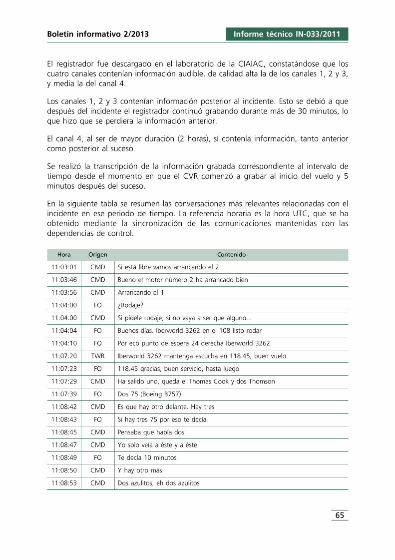
Informe técnico IN-033/2011
65
Boletín informativo 2/2013
El registrador fue descargado en el laboratorio de la CIAIAC, constatándose que loscuatro canales contenían información audible, de calidad alta la de los canales 1, 2 y 3,y media la del canal 4.
Los canales 1, 2 y 3 contenían información posterior al incidente. Esto se debió a quedespués del incidente el registrador continuó grabando durante más de 30 minutos, loque hizo que se perdiera la información anterior.
El canal 4, al ser de mayor duración (2 horas), sí contenía información, tanto anteriorcomo posterior al suceso.
Se realizó la transcripción de la información grabada correspondiente al intervalo detiempo desde el momento en que el CVR comenzó a grabar al inicio del vuelo y 5minutos después del suceso.
En la siguiente tabla se resumen las conversaciones más relevantes relacionadas con elincidente en ese periodo de tiempo. La referencia horaria es la hora UTC, que se haobtenido mediante la sincronización de las comunicaciones mantenidas con lasdependencias de control.
Hora Origen Contenido
11:03:01 CMD Si está libre vamos arrancando el 2
11:03:46 CMD Bueno el motor número 2 ha arrancado bien
11:03:56 CMD Arrancando el 1
11:04:00 FO ¿Rodaje?
11:04:00 CMD Si pídele rodaje, si no vaya a ser que alguno...
11:04:04 FO Buenos días. Iberworld 3262 en el 108 listo rodar
11:04:10 FO Por eco punto de espera 24 derecha Iberworld 3262
11:07:20 TWR Iberworld 3262 mantenga escucha en 118.45, buen vuelo
11:07:23 FO 118.45 gracias, buen servicio, hasta luego
11:07:29 CMD Ha salido uno, queda el Thomas Cook y dos Thomson
11:07:39 FO Dos 75 (Boeing B757)
11:08:42 CMD Es que hay otro delante. Hay tres
11:08:43 FO Si hay tres 75 por eso te decía
11:08:45 CMD Pensaba que había dos
11:08:47 CMD Yo solo veía a éste y a éste
11:08:49 FO Te decía 10 minutos
11:08:50 CMD Y hay otro más
11:08:53 CMD Dos azulitos, eh dos azulitos
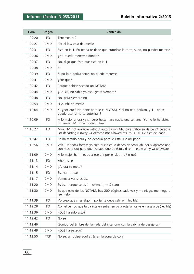
66
Informe técnico IN-033/2011 Boletín informativo 2/2013
Hora Origen Contenido
11:09:20 FO Tenemos H-2
11:09:27 CMD Por el low cost del medio
11:09:31 FO Está en H-1. En teoría te tiene que autorizar la torre, si no, no puedes meterte
11:09:36 CMD ¿No puedo meterme dónde?
11:09:37 FO No, digo que éste que está en H-1
11:09:38 CMD Sí
11:09:39 FO Si no lo autoriza torre, no puede meterse
11:09:41 CMD ¿Por qué?
11:09:42 FO Porque habían sacado un NOTAM
11:09:44 CMD ¿Ah sí?, no sabía yo eso. ¿Para siempre?
11:09:48 FO No, para siempre no
11:09:53 CMD H-2. Ahí en medio
11:10:04 CMD Y, ¿por qué? No pone porque el NOTAM. Y si no te autorizan, ¿H-1 no sepuede usar si no te autorizan?
11:10:09 FO A lo mejor ahora ya sí, pero hasta hace nada, una semana. Yo no lo he visto.En teoría H-1 no se podía utilizar
11:10:27 FO Mira, H-1 not avalaible without autorizacion ATC para tráfico salida de 24 derecha.For departing runway 24 derecha not allowed taxi to H1 si H-2 está ocupada
11:10:47 FO Se ha metido aquí y no debería porque está H-2 ocupado
11:10:56 CMD Vale. De todas formas yo creo que esto lo deben de tener ahí por si aparece unocon mucho slot para que no tape uno de éstos, dicen métete ahí y ya te avisaré
11:11:09 CMD A lo mejor han metido a ese ahí por el slot, no? o no?
11:11:13 FO Ahora sale
11:11:14 CMD ¿Ahora se mete?
11:11:15 FO Ése va a rodar
11:11:17 CMD Vamos a ver si es ése
11:11:20 CMD Es ése porque se está moviendo, está claro
11:11:30 CMD Es que esto de los NOTAM, hay 200 páginas cada vez y me niego, me niego aleérmelo
11:11:39 FO Yo creo que si es algo importante debe salir en (ilegible)
11:12:28 FO Con el tiempo que tarda éste en entrar en pista estaríamos ya en la sala de (ilegible)
11:12:36 CMD ¿Qué ha sido esto?
11:12:42 FO No sé
11:12:46 (Sonido del timbre de llamada del interfono con la cabina de pasajeros)
11:12:49 CMD ¿Qué ha pasado?
11:12:50 TCP No sé, un golpe aquí atrás en la zona de cola

Informe técnico IN-033/2011
67
Boletín informativo 2/2013
1.10.1.2. Registrador de datos de vuelo (FDR)
La aeronave estaba equipada con un registrador de datos de vuelo (FDR), Allied Signal,con P/N: 980-4700-042 y S/N: SSFDR-16667, que fue descargado en el laboratorio dela CIAIAC.
El gráfico de la figura 3 contiene la evolución de varios parámetros: aceleraciones lateraly longitudinal, N2 de ambos motores, velocidad respecto del suelo, rumbo y pulsado delbotón de comunicaciones, entre las 11:03:52 UTC y 11:13:43 UTC.
La hora que figura en el gráfico es la del registrador de datos (FDR). Al hacer lasincronización de comunicaciones se comprobó que la hora del registrador tiene undesfase de 1 s respecto a la hora de la torre de control, de forma que para obtener lahora UTC hay que sumarle 1 s.
La tripulación inició la secuencia de arranque de motores a las 11:03:05 UTC,comenzando con el motor n.° 2 (derecho). Alrededor de 1 min después procedió alarranque del motor n.° 1 (izquierdo), de forma que a las 11:04:30 UTC ya estabanambos motores en marcha a ralentí de tierra.
Figura 3. Evolución de las aceleraciones lateral y longitudinal, N2 de motores, velocidad respecto delsuelo, rumbo y pulsado del botón de comunicaciones. Aeronave Airbus A320, matrícula EC-LAJ
68
Informe técnico IN-033/2011 Boletín informativo 2/2013
A las 11:04:04 UTC, reflejado por la pulsación de VHF en el gráfico 3, llamaron a controlde rodadura para indicar que estaban listos para rodar.
A las 11:05:00 el avión comienza a moverse, y a las 11:06:00 llega a la intersección dela calle de rodaje «North», y vira a la derecha para continuar por ella (rumbo 06). A las11:10:50 UTC la aeronave alcanza la zona de acceso a la pista (puntos de espera H-1,H-2 y H-3) y reduce su velocidad para virar a la izquierda. Finalmente queda detenida alas 11:11:00 con rumbo 328°.
En el gráfico de la figura 3 puede observarse que a las 11:12:37 se produjo unapequeña variación en los valores de ambas aceleraciones, si bien mayor en la lateral,posiblemente debido a la colisión entre ambas aeronaves.
1.10.2. Aeronave LN-RRH
1.10.2.1. Registrador de voces en cabina (CVR)
La aeronave estaba equipada con un registrador de voces en cabina (CVR) Honeywell980-6022-001, S/N CVR120-12882, que grababa cuatro canales. En los canales 1, 2y 3 se graban las señales procedentes de los micrófonos de comunicaciones de lostripulantes y tienen una duración de 30 minutos cada uno. En el cuarto canal se registran los sonidos captados por el micrófono de ambiente y su duración es de2 horas.
El registrador fue descargado en el laboratorio de la CIAIAC, constatándose que loscuatro canales contenían información audible, de calidad alta la de los canales 1, 2 y 3,y media la del canal 4.
Los canales 1, 2 y 3 contenían información posterior al incidente. Esto se debió a quedespués del incidente el registrador continuó grabando durante más de 30 minutos, loque hizo que se perdiera la información anterior.
El canal 4, al ser de mayor duración (2 horas), si contenía información, tanto anteriorcomo posterior al suceso.
Las conversaciones grabadas en el CVR estaban parte en sueco, parte en noruego yparte en inglés. Para la transcripción se requirió el apoyo de la Comisión de Investigaciónde Accidentes de Suecia, «Statents Haverikommision» (SHK).
Dicha Comisión realizó la transcripción de la información grabada correspondiente a unintervalo de tiempo comprendido entre unos 2:41 minutos antes del suceso hasta 1:11minutos después.
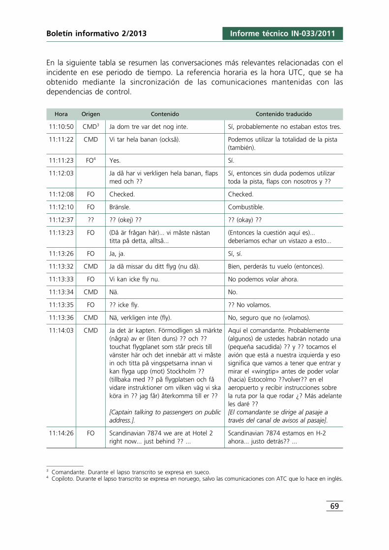
3 Comandante. Durante el lapso transcrito se expresa en sueco.4 Copiloto. Durante el lapso transcrito se expresa en noruego, salvo las comunicaciones con ATC que lo hace en inglés.
Informe técnico IN-033/2011
69
Boletín informativo 2/2013
En la siguiente tabla se resumen las conversaciones más relevantes relacionadas con elincidente en ese periodo de tiempo. La referencia horaria es la hora UTC, que se haobtenido mediante la sincronización de las comunicaciones mantenidas con lasdependencias de control.
Hora Origen Contenido Contenido traducido
11:10:50 CMD3 Ja dom tre var det nog inte. Sí, probablemente no estaban estos tres.
11:11:22 CMD Vi tar hela banan (också). Podemos utilizar la totalidad de la pista(también).
11:11:23 FO4 Yes. Sí.
11:12:03 Ja då har vi verkligen hela banan, flaps Sí, entonces sin duda podemos utilizarmed och ?? toda la pista, flaps con nosotros y ??
11:12:08 FO Checked. Checked.
11:12:10 FO Bränsle. Combustible.
11:12:37 ?? ?? (okej) ?? ?? (okay) ??
11:13:23 FO (Då är frågan här)... vi måste nästan (Entonces la cuestión aquí es)...titta på detta, alltså... deberíamos echar un vistazo a esto...
11:13:26 FO Ja, ja. Sí, sí.
11:13:32 CMD Ja då missar du ditt flyg (nu då). Bien, perderás tu vuelo (entonces).
11:13:33 FO Vi kan icke fly nu. No podemos volar ahora.
11:13:34 CMD Nä. No.
11:13:35 FO ?? icke fly. ?? No volamos.
11:13:36 CMD Nä, verkligen inte (fly). No, seguro que no (volamos).
11:14:03 CMD Ja det är kapten. Förmodligen så märkte Aquí el comandante. Probablemente(några) av er (liten duns) ?? och ?? (algunos) de ustedes habrán notado unatouchat flygplanet som står precis till (pequeña sacudida) ?? y ?? tocamos elvänster här och det innebär att vi måste avión que está a nuestra izquierda y esoin och titta på vingspetsarna innan vi significa que vamos a tener que entrar ykan flyga upp (mot) Stockholm ?? mirar el «wingtip» antes de poder volar(tillbaka med ?? på flygplatsen och få (hacia) Estocolmo ??volver?? en elvidare instruktioner om vilken väg vi ska aeropuerto y recibir instrucciones sobreköra in ?? jag får) återkomma till er ?? la ruta por la que rodar ¿? Más adelante
les daré ??[Captain talking to passengers on public [El comandante se dirige al pasaje aaddress.]. través del canal de avisos al pasaje].
11:14:26 FO Scandinavian 7874 we are at Hotel 2 Scandinavian 7874 estamos en H-2right now... just behind ?? ... ahora... justo detrás?? ...
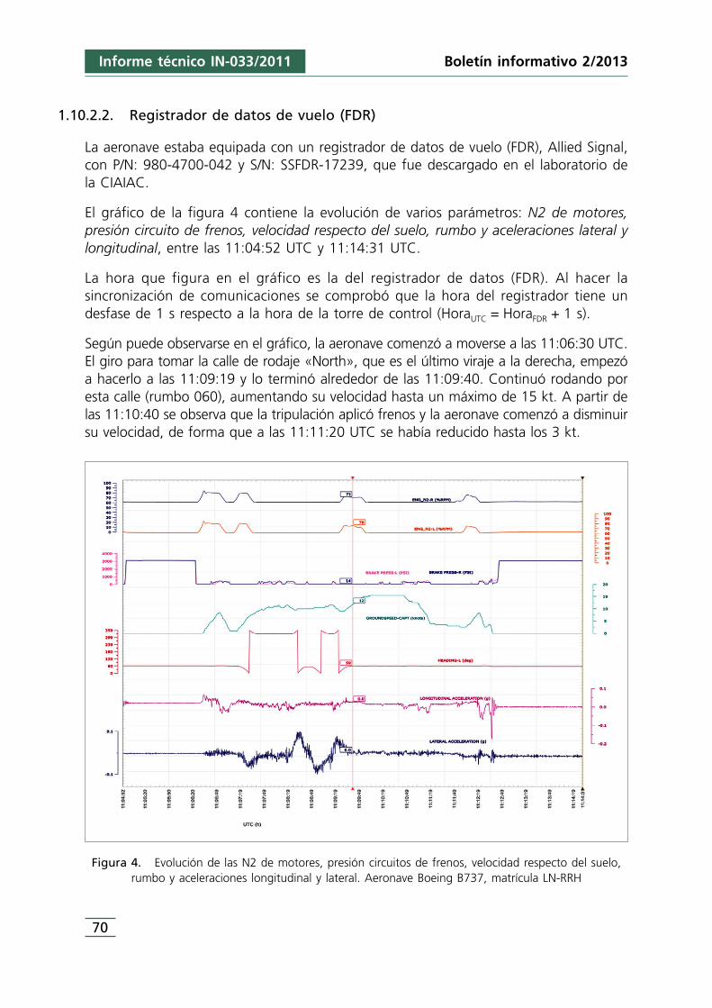
70
Informe técnico IN-033/2011 Boletín informativo 2/2013
1.10.2.2. Registrador de datos de vuelo (FDR)
La aeronave estaba equipada con un registrador de datos de vuelo (FDR), Allied Signal,con P/N: 980-4700-042 y S/N: SSFDR-17239, que fue descargado en el laboratorio dela CIAIAC.
El gráfico de la figura 4 contiene la evolución de varios parámetros: N2 de motores,presión circuito de frenos, velocidad respecto del suelo, rumbo y aceleraciones lateral ylongitudinal, entre las 11:04:52 UTC y 11:14:31 UTC.
La hora que figura en el gráfico es la del registrador de datos (FDR). Al hacer lasincronización de comunicaciones se comprobó que la hora del registrador tiene undesfase de 1 s respecto a la hora de la torre de control (HoraUTC = HoraFDR + 1 s).
Según puede observarse en el gráfico, la aeronave comenzó a moverse a las 11:06:30 UTC.El giro para tomar la calle de rodaje «North», que es el último viraje a la derecha, empezóa hacerlo a las 11:09:19 y lo terminó alrededor de las 11:09:40. Continuó rodando poresta calle (rumbo 060), aumentando su velocidad hasta un máximo de 15 kt. A partir delas 11:10:40 se observa que la tripulación aplicó frenos y la aeronave comenzó a disminuirsu velocidad, de forma que a las 11:11:20 UTC se había reducido hasta los 3 kt.
Figura 4. Evolución de las N2 de motores, presión circuitos de frenos, velocidad respecto del suelo,rumbo y aceleraciones longitudinal y lateral. Aeronave Boeing B737, matrícula LN-RRH
Informe técnico IN-033/2011
71
Boletín informativo 2/2013
Continuaron durante algo menos de 1 minuto avanzando a baja velocidad. Luego laaumentaron ligeramente, y alrededor de 20 s después aplicaron frenos y redujeron lavelocidad hasta 2-3 kt.
Como puede apreciarse en el gráfico de la figura 4, a las 11:12:37 quedó registradauna pequeña variación de los valores de las aceleraciones lateral y longitudinal, einmediatamente después se registró un aumento significativo en la presión del circuitode frenos y la detención de la aeronave.
Segundos antes se aprecia que se produjo una pequeña variación (incremento) delrumbo de la aeronave («heading»), lo que significa que se hizo un ligero viraje hacia laderecha.
1.11. Información sobre organización y gestión
1.11.1. Skandinavian Airlines (SAS)
Preparación del vuelo
El vuelo fue preparado utilizando el sistema de planificación de vuelo «RODOS», durantela mañana del día del incidente antes del despegue de Estocolmo. Se obtuvo toda lainformación disponible sobre ruta y aeródromo, no apreciando la existencia deinformación relativa a restricciones de rodaje en las calles de rodaje o puntos de esperade la pista 24R del Aeropuerto de Palma de Mallorca.
El sistema RODOS utiliza la base de datos AIS de Eurocontrol como proveedor universalde NOTAM.
Este sistema dispone de un filtro «piloto» pre-programado, que utiliza el código Q delos NOTAM, concretamente la segunda y tercera letras, para detectar y resaltarautomáticamente cualquier nuevo NOTAM que sea relevante para las tripulaciones.También utiliza el campo «propósito» de forma que solamente están disponibles paralas tripulaciones aquellos NOTAM que contengan los calificadores N, B u O.
Dicho filtro fue diseñado en base a los aspectos que los pilotos de SAS y susdespachadores de vuelos juzgaron que podían ser relevantes para las operaciones.
Concretamente el código de segunda y tercera letras que tenía el NOTAM delaeropuerto de Palma de Mallorca, MX, es uno de los códigos que utiliza el filtro.
Asimismo, el sistema utiliza otro criterio basado en el campo calificador, de forma queaquellos NOTAM que contienen una M no pasan el filtro al considerar que, por la
5 SAS despacho de vuelos/plan de vuelo.
72
Informe técnico IN-033/2011 Boletín informativo 2/2013
definición del calificador, se trata de asuntos varios que no están destinados a apareceren los boletines de información previa al vuelo, a menos que se requieran de formaespecífica.
Cualquier nuevo NOTAM que es automáticamente resaltado (no filtrado) por el sistema,es posteriormente evaluado por CPHOW5 con objeto de eliminar la información que nosea operacionalmente relevante para los pilotos.
Los NOTAM sobre las restricciones de rodaje en los puntos de espera H-1 y H-2 teníanel código QMXXX, y el campo propósito contenía una «M». Como se ha indicadoanteriormente, el filtro automático del sistema RODOS desecha los NOTAM quecontienen una M en el campo propósito. Por este motivo entre la documentación dedespacho de vuelo entregada a la tripulación no figuraba el NOTAM B6407/11.
Procedimientos de rodaje
En OM-A 8.4.1.2.3 se determina que «normalmente un avión no deberá rodar a menosdistancia de 1/4 de la envergadura de la aeronave respecto a cualquier obstáculo».
Así mismo, indica que es responsabilidad del PNF informar al PF en cualquier momentoen el que el avión vaya a rodar a menos de 1/4 de envergadura respecto a un obstáculosituado en su lado. Indica además que las líneas o marcas de rodaje no siempreaseguran una adecuada separación con los obstáculos, por lo que deben ser seguidascon precaución.
Los «wingtips» de la aeronave son claramente visibles desde cualquiera de los dospuestos, izquierdo o derecho, de la cabina de vuelo.
1.11.2. Orbest
Preparación del vuelo
Este operador no dispone de ningún sistema de filtrado de los NOTAM, motivo por elcual las tripulaciones de vuelo reciben todos los NOTAM publicados que afecten opuedan afectar al vuelo a realizar, es decir, aquellos relativos a los aeródromos de salida,destino y alternativos, así como los de la ruta a seguir.
El operador reconoce que de esta forma el número de NOTAM que las tripulacionesdeben revisar en cada vuelo es sumamente elevado, por lo que si bien asegura que se
Informe técnico IN-033/2011
73
Boletín informativo 2/2013
recibe toda la información necesaria, el elevado volumen de información que ha demanejarse puede propiciar que su evaluación pueda no ser adecuada.
1.11.3. AENA
El Real decreto 905/1991, de 14 de junio, por el que se aprueba el estatuto del entepúblico aeropuertos españoles y navegación aérea (AENA) asigna a este Ente, entre otrasfunciones, las correspondientes a los servicios de información aeronáutica.
El servicio de información aeronáutica (AIS) es proporcionado por AENA a través de laOficina AIS.
La estructura, organización y responsabilidades de la oficina AIS están recogidos en elManual de procedimientos AIS V3.0, editado por AENA. De acuerdo con él, la oficinaAIS está formada por 3 dependencias:
• La División AIS (servicios centrales de navegación aérea).• La oficina NOTAM Internacional (NOF), que está integrada en los servicios centrales
de navegación aérea.• Las oficinas de información aeronáutica (AIO) y/o las oficinas de notificación de los
servicios de tránsito aéreo (ARO) de los aeropuertos y centros de control.
Los proyectos de nuevos NOTAM son elaborados por las dependencias afectadas(aeropuertos, centros de control, etc.) y posteriormente son remitidos por las AIO/AROde estos centros a la oficina NOTAM Internacional (NOF).
Entre las responsabilidades de la NOF figura la de verificar y aprobar, si procede, losproyectos NOTAM recibidos de las AIS/ARO y otros departamentos y estamentosautorizados, para posteriormente distribuirlos como NOTAM.
1.12. Información adicional
1.12.1. Normativa de los Servicios de Información Aeronáutica
Los servicios de información aeronáutica, a nivel internacional, están regulados por elAnexo 15 de la OACI «Servicios de información aeronáutica», el Doc. 8126 de OACI«Manual para los servicios de información aeronáutica» y el Doc. 8400 de OACI«Abreviaturas y códigos de la OACI».
El doc. 8126 contiene información sobre el contenido de los campos, así como acercade la codificación de los NOTAM.
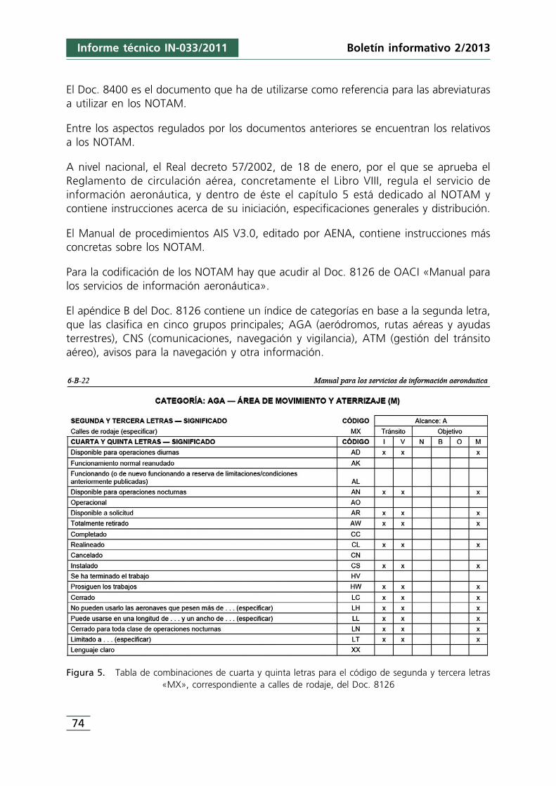
74
Informe técnico IN-033/2011 Boletín informativo 2/2013
El Doc. 8400 es el documento que ha de utilizarse como referencia para las abreviaturasa utilizar en los NOTAM.
Entre los aspectos regulados por los documentos anteriores se encuentran los relativosa los NOTAM.
A nivel nacional, el Real decreto 57/2002, de 18 de enero, por el que se aprueba elReglamento de circulación aérea, concretamente el Libro VIII, regula el servicio deinformación aeronáutica, y dentro de éste el capítulo 5 está dedicado al NOTAM ycontiene instrucciones acerca de su iniciación, especificaciones generales y distribución.
El Manual de procedimientos AIS V3.0, editado por AENA, contiene instrucciones másconcretas sobre los NOTAM.
Para la codificación de los NOTAM hay que acudir al Doc. 8126 de OACI «Manual paralos servicios de información aeronáutica».
El apéndice B del Doc. 8126 contiene un índice de categorías en base a la segunda letra,que las clasifica en cinco grupos principales; AGA (aeródromos, rutas aéreas y ayudasterrestres), CNS (comunicaciones, navegación y vigilancia), ATM (gestión del tránsitoaéreo), avisos para la navegación y otra información.
Figura 5. Tabla de combinaciones de cuarta y quinta letras para el código de segunda y tercera letras«MX», correspondiente a calles de rodaje, del Doc. 8126
6 Corresponde a las siglas de «Aeronautical Information Management».
Informe técnico IN-033/2011
75
Boletín informativo 2/2013
El grupo AGA está subdividido en tres subgrupos: L (instalaciones de iluminación), M(área de movimiento y aterrizaje) y F (instalaciones y servicios). Dada la naturaleza del«asunto» el subgrupo en el que habría de clasificarse es el M, que sería la segunda letradel código.
La tercera letra del código identifica una parte concreta dentro del subgrupo de que setrate. En este caso el subgrupo M (área de movimiento y aterrizaje) contiene 18 zonasdiferentes a cada una de las cuales le corresponde una letra diferente. Las calles derodaje tienen asignada la letra X (tercera letra del código).
El objeto del código NOTAM es codificar estos documentos, a fin de que mediante estecódigo se pueda determinar claramente el asunto de que se trata (segunda y terceraletras) y su estado (cuarta y quinta letras).
Fruto de la colaboración entre la Organización Europea para la Seguridad de laNavegación Aérea (EUROCONTROL) y la OACI, en junio de 2006 se celebró un Congresomundial de AIS en Madrid, en el que se abordó el papel del AIS en el entorno de ATM,que está en constante evolución. En el mismo se tomó nota del hecho de que lossistemas de navegación basados en computadora, la navegación de área (RNAV), laperformance de navegación requerida (RNP) y los requisitos de ATM han hechonecesario introducir nuevos requisitos en materia de AIS por lo que respecta a la calidady la puntualidad de la información, concluyendo que era necesario efectuar unatransición de la función de los AIS a un servicio de gestión de la información (AIM)6, connuevos cometidos, responsabilidades y alcance, a fin de satisfacer las nuevas necesidadesy poder hacer frente a la demanda de información y gestionar la provisión de la misma.
La OACI ha elaborado una hoja de ruta para llevar a cabo la transición a este nuevomodelo, que prevé su implementación en tres fases, que, en principio, culminarían ennoviembre de 2016.
La transición hacia este nuevo modelo requerirá la revisión en profundidad de toda ladocumentación de referencia.
1.12.2. El NOTAM
Un NOTAM es un aviso distribuido por medio de telecomunicaciones que contieneinformación relativa al establecimiento, condición o modificación de cualquier instalaciónaeronáutica, servicio, procedimiento o peligro, cuyo conocimiento oportuno es esencialpara el personal encargado de las operaciones de vuelo, y su difusión se realiza a travésde los servicios de información aeronáutica.
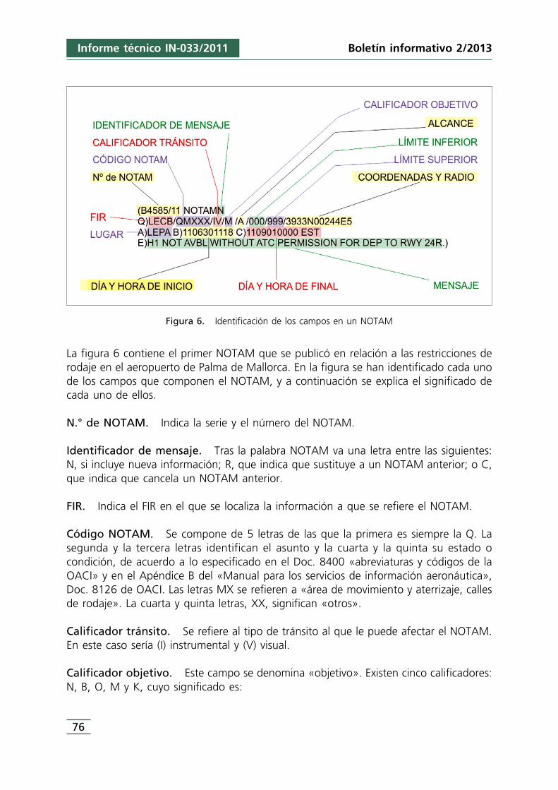
76
Informe técnico IN-033/2011 Boletín informativo 2/2013
Figura 6. Identificación de los campos en un NOTAM
La figura 6 contiene el primer NOTAM que se publicó en relación a las restricciones derodaje en el aeropuerto de Palma de Mallorca. En la figura se han identificado cada unode los campos que componen el NOTAM, y a continuación se explica el significado decada uno de ellos.
N.° de NOTAM. Indica la serie y el número del NOTAM.
Identificador de mensaje. Tras la palabra NOTAM va una letra entre las siguientes:N, si incluye nueva información; R, que indica que sustituye a un NOTAM anterior; o C,que indica que cancela un NOTAM anterior.
FIR. Indica el FIR en el que se localiza la información a que se refiere el NOTAM.
Código NOTAM. Se compone de 5 letras de las que la primera es siempre la Q. Lasegunda y la tercera letras identifican el asunto y la cuarta y la quinta su estado ocondición, de acuerdo a lo especificado en el Doc. 8400 «abreviaturas y códigos de laOACI» y en el Apéndice B del «Manual para los servicios de información aeronáutica»,Doc. 8126 de OACI. Las letras MX se refieren a «área de movimiento y aterrizaje, callesde rodaje». La cuarta y quinta letras, XX, significan «otros».
Calificador tránsito. Se refiere al tipo de tránsito al que le puede afectar el NOTAM.En este caso sería (I) instrumental y (V) visual.
Calificador objetivo. Este campo se denomina «objetivo». Existen cinco calificadores:N, B, O, M y K, cuyo significado es:
Informe técnico IN-033/2011
77
Boletín informativo 2/2013
• N, NOTAM seleccionado para que los explotadores de aeronaves le presten inmediataatención.
• B, NOTAM seleccionado para una entrada en el boletín de información previa al vuelo(PIB).
• O, NOTAM relativo a las operaciones de vuelo.• M, NOTAM sobre asuntos varios, no sujeto a aleccionamiento pero disponible a
solicitud.• K, el NOTAM es una lista de verificación.
Este campo puede contener los calificadores combinados siguientes: K, B, BO, NBO oM. El Apéndice B del «Manual para los servicios de información aeronáutica», Doc. 8126de OACI, contiene orientación sobre la combinación de calificadores «objetivo», enfunción del asunto y contenido del NOTAM (código). La tabla que figura en la página6-B-22 de dicho manual contiene el código de este asunto, MXXX, aunque no defineningún calificador para éste.
Alcance. Puede referirse a aeródromo (A), en ruta (E), aviso Nav (W), o lista deverificación (K). En este caso es aeródromo.
Límite inferior. Si el asunto no contiene información específica sobre la altura seinsertará 000 para el límite inferior.
Límite superior. Si el asunto no contiene información específica sobre la altura seinsertará 999 para el límite superior.
Coordenadas y radio. Indica las coordenadas y el radio de influencia en NM. Si elalcance del NOTAM es «A» se insertarán las coordenadas del punto de referencia delaeródromo.
Lugar. Indicador de lugar OACI a que se refiere la información.
Día y hora de inicio. Indica el día y hora de inicio del suceso.
Día y hora de fin. Indica el día y hora de finalización del suceso. El código «EST»indica que la duración es aproximada. Si la información es permanente figurará «PERM».
Mensaje. A este campo se le denomina texto y contiene la información que se tratade difundir. Habitualmente incluye códigos de los contemplados en el Doc. 8400,«abreviaturas y códigos» de la OACI.
1.12.3. Declaraciones
Los tripulantes de la aeronave operada por SAS no fueron entrevistados personalmentey formularon sus declaraciones por escrito.
SAS – Comandante
La planificación del vuelo de ida y vuelta entre Estocolmo y Palma de Mallorca fuenormal. La información disponible no revelaba ninguna circunstancia excepcional. Elvuelo de ida hasta Palma fue normal.
La escala en Palma, así como las actividades previas al vuelo de vuelta, se desarrollaronigualmente con normalidad y estuvieron en condiciones de partir antes de la horaprogramada.
Fueron autorizados a rodar a pista 24R vía I-7, F. Cuando comenzaron el rodajesolicitaron y obtuvieron confirmación de la autorización.
Ese día había mucho tráfico en la plataforma por lo que rodaron despacio, sin quehubiera ninguna presión por parte de GMC. Durante el rodaje por la calle Northcambiaron la frecuencia de comunicaciones a la de la torre de control.
Cree recordar que cuando estaban llegando al área de espera de la pista 24R había unavión en H-3 y que en H-2 había un A320 de Orbest. Como el peso del avión erarelativamente alto decidió utilizar la totalidad de la pista 24R, para lo que tenía queacceder a través de H-1.
Dirigió la aeronave hacia H-1 y al llegar a la altura de H-3 el copiloto le preguntó ¿esposible? Él inmediatamente entendió que se refería al A320 que estaba en H-2 por loque giró ligeramente a la derecha, y volvió la cabeza a la izquierda para ver el extremodel plano de ese lado y estimó que había suficiente espacio para pasar. La velocidad dela aeronave era muy baja, del orden de 2 o 3 kt. Se dieron cuenta inmediatamente queel «winglet» del plano izquierdo de su avión había contactado con el A320 y detuvieronla aeronave rápidamente. A continuación llamaron a la torre de control para informarde lo ocurrido.
Se comunicaron con la tripulación del A320 por la frecuencia de radio de la torre decontrol y les pidió que permanecieran donde estaban, que no encendieran el APU y queapagaran el motor derecho ya que el chorro de éste incidía sobre el avión.
SAS – Copiloto
Coincidió con el comandante en que el vuelo de ida a Palma y los preparativos para elvuelo de regreso a Estocolmo se desarrollaron con plena normalidad.
Después de hacer el retroceso de la aeronave desde el stand 46, pidieron autorizaciónde rodaje a movimientos en tierra (GMC), que les autorizaron a rodar vía F y esperaren 24R.
Boletín informativo 2/2013Informe técnico IN-033/2011
78
Maniobraron cuidadosamente en la plataforma, ya que había mucho tráfico, y solicitóa GMC que le confirmase sí debía usar I-7 y luego F, lo que le fue confirmado.
Cuando estaban llegando a la intersección con la calle North vio otro avión, unMonarch, llegando por su izquierda. GMC les confirmó que ellos eran número 1.Giraron a la derecha para continuar por la calle North en dirección al punto de esperade la pista 24R. Cambió la frecuencia de la radio a la de la torre de control.
Cuando estaban llegando al punto de espera de la pista 24R observó que había otraaeronave detenida en el punto de espera H-3, un Boeing757 de TUI, y otro avión,concretamente un A320 de Orbest, detenida en H-2. Asimismo, otra aeronave acababade alinearse en pista a través de H-1.
Aproximadamente cuando llegaron a la altura de H-3 el comandante le dijo que teníaintención de continuar hacia H-1. Él pensó que pararían antes de llegar a H-2 debido ala presencia de un avión en él, pero cuando se dio cuenta que no lo hacía le preguntósi era posible.
La velocidad a la que rodaban era muy baja y el comandante la redujo aún más, giróligeramente a la derecha para separarse más de la otra aeronave, miró fuera y dijo «esposible».
Segundos después notó un suave movimiento en el avión cuando el extremo del planoizquierdo impactó contra la cola del A320, y el comandante detuvo inmediatamente laaeronave.
Oyó por la radio que la tripulación de otro avión, posiblemente del Monarch que ibatras ellos, informaba «SK le habéis golpeado».
1.12.4. Medidas tomadas por AENA
La primera medida adoptada fue el cierre de la calle de rodaje H-1, tal y como se indicaen el punto 1.9.3.
Con posterioridad al incidente el aeropuerto realizó una evaluación del suceso,identificando varios puntos respecto a los que parecía aconsejable adoptar medidascorrectoras, que en síntesis son los siguientes:
• Reforzar el procedimiento de seguimiento de la implantación de medidas demitigación de riesgos con un doble objeto. Por una parte la vigilancia y evaluación dela efectividad de las medidas mitigadoras adoptadas, y por otra prever la posibilidadde que cuando por alguna circunstancia no pueda implantarse alguna de las medidasplaneadas, se reevalúe la situación y se establezcan otras barreras de seguridadalternativas que garanticen un nivel de seguridad aceptable.
Boletín informativo 2/2013
79
Informe técnico IN-033/2011
80
Informe técnico IN-033/2011 Boletín informativo 2/2013
• Cualquier actuación que conlleve aparejados cambios operativos importantes en elaeropuerto deberá contar con el asesoramiento de pilotos.
• Proponer la instalación de un sistema de vigilancia y grabación de las operaciones enel área de maniobras, en especial en cabeceras.
• Cualquier acción que implique un cambio en la configuración de las pistas o las callesde rodaje deberá llevarse a cabo preferentemente en temporada baja, y se habráplanificado con la mayor antelación posible, a no ser que su urgencia lo impida.
1.12.5. Medidas tomadas por Skandinavian Airlines (SAS)
SAS revisó su manual de operaciones a fin de enfatizar la importancia de que lastripulaciones mantengan las distancias mínimas de seguridad durante el rodaje. Asímismo, en dicho documento también se incluyeron instrucciones para clarificar lasdiferencias que existen con este respecto a distancias mínimas, entre un rodaje deacceso a un puesto de estacionamiento y un rodaje estándar.
1.12.6. Medidas tomadas por Orbest
Orbest estaba estudiando la viabilidad de implementar un sistema de filtrado de losNOTAM.
2. ANÁLISIS
2.1. Situación en el punto de espera de la pista 24R
A las 11:08:06 el controlador autorizó la entrada en pista a la aeronave TOM19K, y alas 11:10:45 autorizó su despegue. Después de esto, concretamente a las 11:10:56,comunicó a la aeronave TOM9FT que estaba autorizada a despegar detrás del TOM19K.
De las conversaciones grabadas en el CVR de la aeronave EC-LAJ se deduce que cuandoesta aeronave estaba llegando a la zona de espera de la pista 24R, los puntos de esperaH-1 y H-3 debían estar ocupados, puesto que comentaron: «tenemos H-2. Por el lowcost del medio», y segundos después el copiloto añadió: «está en H-1».
De estas mismas conversaciones se infiere que la aeronave TOM19K inició su entrada ala pista a las 11:11:13 h.
Por otra parte, de las comunicaciones mantenidas por las distintas dependencias decontrol se desprende que ninguna de las aeronaves fue instruida o autorizada a dirigirsea un punto de espera concreto, por lo que fueron sus tripulaciones las que decidieron
Informe técnico IN-033/2011
81
Boletín informativo 2/2013
a través de qué punto de espera accederían a la pista, posiblemente en función de lasituación del momento en el que llegaron.
De este hecho se deducen tres conclusiones: la tripulación de la aeronave TOM19K noera consciente de la restricción de rodaje que afectaba al punto de espera H-1; no habíaninguna señalización o indicación en esa zona del campo de vuelos que permitiera intuirla existencia de la restricción y los controladores que se encontraban en la torre decontrol no advirtieron que había aeronaves utilizando H-1.
2.2. Rodaje de la aeronave LN-RRH
De acuerdo con las conclusiones establecidas en el punto anterior y de la información delFDR de la aeronave LN-RRH se puede determinar que, en el momento en que la aeronaveTOM19K comenzó a moverse desde el punto de espera en el que se encontraba (H-1)para entrar a la pista, la aeronave LN-RRH se encontraba en la calle de rodaje «North»a menos de 100 m de la zona de espera. Desde esa posición la tripulación pudo observarperfectamente que la aeronave TOM19K accedía a la pista desde el punto de espera H-1, como así lo declaró el copiloto, según se refleja en 1.13.3.
Los puntos de espera H-2 y H-3 se encontraban ocupados por las aeronaves EC-LAJ yTOM9FT.
Así pues, cuando la aeronave llegó a la zona de espera de la pista 24R sólo estaba libreel punto de espera H-1, que acababa de quedar desocupado al acceder a la pista laaeronave TOM19K desde él.
En una situación como la descrita, la forma habitual de actuar es hacerlo de la maneraen que lo hizo la tripulación de la aeronave LN-RRH, es decir, dirigirse hacia el punto deespera que acababa de quedar libre, y que era el único que estaba desocupado.Además, en este caso hay que tener en cuenta que la aeronave tenía un pesorelativamente alto por lo que era lógico que la tripulación tratara de acceder a la pistapor H-1, ya que de esta forma disponía de mayor longitud de pista.
Ya al acercarse a la vertical de H-2, es cuando debieron advertir la escasa distancia libreque quedaba para rodar por detrás de la aeronave que había en ese punto de espera,que quedó manifiesta en la pregunta del copiloto «¿cabemos?».
En ese momento debía ser evidente que la distancia libre era inferior a ¼ de laenvergadura de la aeronave, lo que queda patente en el ligero giro a la derecha quedescribió ésta, posiblemente con objeto de aumentar la separación entre las aeronaves.De acuerdo a lo indicado en OM-A 8.4.1.2.3: «normalmente un avión no deberá rodara menos distancia de 1/4 de la envergadura de la aeronave respecto a cualquierobstáculo», la tripulación no debería haber intentado rodar por detrás.
2.3. Planificación de la reubicación de los puntos de espera
A pesar de que fue en el año 2007 cuando se identificó que las superficies limitadorasde obstáculos estaban vulneradas como consecuencia de la ubicación de los puntos deespera H-1 y H-2, aparentemente transcurrieron más de 4 años (hasta la primera mitadde 2011) sin que se iniciara ninguna acción encaminada a subsanar dicha vulneración.
En junio de 2011 se realizó el estudio de identificación de riesgos asociados aldesplazamiento de los puntos de espera H-1 y H-2, y en la primera quincena del messiguiente se llevó a cabo el desplazamiento físico de estos dos puntos de espera.
Resulta llamativo el hecho de que transcurrieran 4 años sin que supuestamente seiniciara ninguna acción correctora de la vulneración de las superficies limitadoras deobstáculos, y que repentinamente en el año 2011, en un plazo inferior a 1 mes, sehiciera la evaluación de riesgos, la elaboración y envío al AIS de la información a publicaren AIP, la publicación del NOTAM anunciando la restricción, ya que no había tiempopara que estuviera difundida la información por AIP antes de la ejecución deldesplazamiento y el desplazamiento físico de los puntos de espera, que se ejecutó enplena temporada alta, a pesar de que el aeropuerto de Palma de Mallorca tiene unagran estacionalidad, por lo que en principio parece que sería preferible que las obras sellevaran a cabo preferiblemente durante la temporada baja.
A la vista de cómo se desarrollaron los acontecimientos da la impresión de que laplanificación fue un tanto precipitada, posiblemente a causa de primarse en exceso laejecución frente a la planificación.
Tal vez por este motivo no se implementó un programa de seguimiento de las medidasmitigadoras previstas en el estudio de identificación de riesgos, ni de control de lapublicación de las restricciones (NOTAM/AIP).
Con relación a este último, conviene examinar la forma en la que se llevó a cabo elcontrol de la publicación de los NOTAM sobre las restricciones. El 30/06/12 se publicóel NOTAM B4590/11 cuya validez estimada se extendía hasta el 1/09/2011. Este NOTAMfue remplazado por el B6407/11, que fue publicado el 16/09/2011, es decir, 16 díasdespués de la teórica finalización del NOTAM anterior.
Aunque a la vista de la información precedente pudiera parecer que el NOTAMB4590/11 expiró, y por ello, dejó de tener validez el día 1/09/2011, hay que señalar queun NOTAM de duración estimada está vigente y activo, en tanto en cuanto no haya sidoremplazado o cancelado. Por lo tanto, cabe concluir que el día del suceso la restricciónpublicada mediante dicho NOTAM era plenamente vigente.
No obstante, esa misma circunstancia evidencia el no cumplimiento de las instruccionescontenidas en el doc. 8126, de OACI, que indica que «se deberá cancelar o sustituir
Boletín informativo 2/2013Informe técnico IN-033/2011
82
cualquier NOTAM en el que esté incluida una indicación “EST” antes de la fecha-horaespecificada en la casilla C)», debido con toda probabilidad a la deficiente planificaciónque no previó un mecanismo de seguimiento y control de la publicación de lainformación.
2.4. Evaluación de riesgos
El estudio de identificación de riesgos inherentes al desplazamiento de los puntos deespera examinó de forma exhaustiva la operativa con los puntos de espera en susnuevas ubicaciones, y concluyó correctamente que había un alto riesgo de colisión entreaeronaves.
El mismo estudio determinó qué medidas habrían de tomarse para mitigar dichoriesgo, que fue fundamentalmente restringir el rodaje hacia H-1 si había otra aeronaveen H-2.
El estudio no ahondó más en el análisis de la situación, no entrando a valorar laefectividad de la forma en que se implementaban las propias medidas correctoras.
En este sentido, conviene señalar varias circunstancias que tuvieron, o pudieron tener,influencia en este aspecto:
1. Las restricciones de rodaje hacia H-1 no eran físicamente evidentes para lastripulaciones de las aeronaves que rodaran por esa zona.
2. La torre de control no asignaba a las aeronaves un punto de espera concreto.3. Desde la torre de control no es posible determinar qué puesto de espera está
utilizando una aeronave.4. La restricción no se había difundido aún a través del AIP.5. La restricción solamente se había hecho pública vía NOTAM.6. Ausencia de seguimiento de las medidas correctoras, que impidió que se alertase
del riesgo derivado de la no implementación de una medida (difusión vía ATIS), yque se previese alguna medida sustitutoria. Esta deficiencia ya ha sido identificadapor los responsables del aeropuerto, que han tomado medidas para asegurar queen el futuro haya un adecuado seguimiento de las medidas correctoras.
7. No intervención de representantes de los operadores. De haber contado con éstospodría haberse valorado más certeramente la idoneidad de las medidas mitigadoras.
En conclusión, al no difundirse la restricción vía ATIS, su implementación quedaba fiadaúnicamente a su difusión vía NOTAM, no existiendo ninguna otra barrera de seguridadcomplementaria, lo que realmente la hacía bastante débil.
Esta afirmación se ve refrendada por el hecho de que en el pequeño lapso de tiempoanalizado en el presente informe, al menos otra aeronave, además de la que se vio
Boletín informativo 2/2013
83
Informe técnico IN-033/2011
involucrada en el suceso, rodó hacia H-1, sin que su tripulación fuera consciente de laexistencia de la restricción y sin que hubiera ningún mecanismo que haya alertado de ello.
De este hecho también se infiere que el NOTAM mediante el que se difundía estainformación o no llegó o no fue correctamente percibido por las tripulaciones.
2.5. Codificación de los NOTAM
Aunque ninguno de los documentos indicados en 1.13.1 especifica claramente cómo hade clasificarse un «asunto», si atendiendo a la naturaleza del hecho de que se trate odel lugar en el que se produce, si se examina detenidamente el índice de categoríascontenido en el apéndice B del capítulo 6 del Doc. 8126, se llega a la conclusión de queha de hacerse en función del lugar.
El «asunto» del caso analizado en el presente informe radicaba en la calle de rodaje«North» del aeropuerto de Palma de Mallorca, por lo que quedaría clasificado en elgrupo AGA.
El código correspondiente a la segunda y tercer letras «MX» admite las combinacionesde tercera y cuarta letra que pueden verse en la tabla de la figura 5. Si el estado del«asunto» no se encuentra entre los relacionados en la tabla se utilizará XX como cuartay quinta letras. En este caso en concreto no parece que ninguno de los estados reflejeadecuadamente el estado del «asunto», que era la restricción de rodaje en esa zona,por lo que puede considerarse adecuada la codificación XX.
Por otra parte, el Doc. 8126, contiene en la categoría AGA-Área de movimiento yaterrizaje (M), una combinación con la A como tercera letra (MA), denominada «áreade movimiento», cuya aplicación no parece estar suficientemente clara.
El Anexo 14 de OACI, define «área de movimiento» como: «parte del aeródromo queha de utilizarse para el despegue, aterrizaje y rodaje de aeronaves, integrada por el áreade maniobras y las plataformas».
De acuerdo con ello, parece que las calles de rodaje o cualquier otra zona del área demovimiento podrían codificarse con la combinación de segunda y tercera letrasespecíficas que les corresponda, MX en el caso de las calles de rodaje, o con la genéricade área de movimiento, MA. Concretamente, el asunto del caso aquí analizado sepodría haber codificado como MXXX o como MAXX.
Aunque la documentación OACI, particularmente el Doc. 8126, deben ser consideradasmeras guías para la elaboración de los NOTAM, ello no ha ser óbice para que lainformación e instrucciones que contengan sean lo menos ambiguas posible, pues deesta forma se mejorará y uniformizará la codificación de los NOTAM.
Boletín informativo 2/2013Informe técnico IN-033/2011
84
En lo que respecta a los campos «tránsito» y «objetivo», la tabla de la figura 5 incluye,para cada combinación de cuarta y quinta letras, información sobre los códigos a asignara estos campos. Llama la atención que a todos los posibles «estados» de las calles derodaje les asigna el objetivo «M», que corresponde a misceláneo. En cambio, si elasunto se hubiera codificado como MA, de acuerdo a lo expuesto en el párrafoprecedente, el objetivo que le correspondería según el Doc. 8126 sería N, B, O.
Resulta llamativo también que, por ejemplo, a la combinación de segunda y terceraletras MK, que corresponde a área de movimiento y aterrizaje – zona deestacionamiento, se les haya asignado mayoritariamente los calificadores de objetivo«O» y «B». Así, por ejemplo, tendríamos que el cierre de un puesto de estacionamiento,cuyo conocimiento no es vital para las tripulaciones ya que los puestos deestacionamiento son asignados por el aeropuerto, gozaría de una mayor relevanciaoperacional (calificadores B y O) que una restricción en una calle de rodaje, cuyaexistencia solamente se conoce a través del NOTAM, ya que, como en la del caso quenos ocupa, no es físicamente reconocible ni es objeto de instrucciones o informaciónpor parte de la torre de control.
De acuerdo con lo expuesto anteriormente, la restricción que afectaba a las calles H-1y H-2 del aeropuerto de Palma de Mallorca podría haberse codificado al menos de dosformas distintas: MXXX y MAXX. Según el Doc. 8126, a estos códigos les corresponderíael calificador objetivo, M en el primer caso y N, B y O en el segundo.
No obstante todo lo anterior, hay que tener en cuenta que las tablas contenidas en elDoc. 8126 muestran los calificadores usados con mayor asiduidad para cadacombinación de letras de código, y que por tanto, han de tomarse como una guía parafacilitar la codificación, pero no como una regla, siendo perfectamente admisible laasignación de calificadores diferentes a los propuestos en la documentación.
En este sentido, la oficina encargada de codificar los NOTAM debería determinar si elcalificador, que según el Doc. 8126 le corresponde a un determinado asunto, esadecuado en base a los principales destinatarios de la información que contenga elmensaje, y en caso de no considerarlo así, establecer el calificador objetivo másconveniente para que el mensaje llegue a sus potenciales destinatarios.
Una vez admitido que el codificador dispone de plena capacidad discrecional paraasignar el calificador que considere más adecuado, el hecho de que el Doc. 8126, encasos como por ejemplo en los supuestos de MX como primera y segunda letra, asignepara todos ellos M como calificador objetivo M, no viene a facilitar a posibilidad de queel codificador asigne uno diferente.
No obstante, esta circunstancia no debería propiciar que las instrucciones de ladocumentación de referencia fuesen aplicadas a rajatabla, que es lo que pudo sucederen el caso del NOTAM de publicación de las restricciones de rodaje en el aeropuerto de
Boletín informativo 2/2013
85
Informe técnico IN-033/2011
86
Informe técnico IN-033/2011 Boletín informativo 2/2013
Palma de Mallorca. Atendiendo la gran trascendencia operacional de éste, parece quedebería haber sido codificado con las letras N, B, O, en lugar de M.
Por otra parte, esta flexibilidad en la asignación de los códigos en general, y delcalificador «objetivo» en particular, no debería alcanzar un grado de libertad tal quehaga inviable la clasificación y/o el filtrado de los NOTAM.
A este respecto, conviene tener en cuenta el hecho de que el número de NOTAMpublicados es sumamente elevado, lo que obligaría a las tripulaciones a tener que revisarun numero ingente de NOTAM antes de iniciar cada vuelo, en el caso de que no hubieraun filtrado previo. Por este motivo, muchos operadores han implementado sistemasautomáticos de tratamiento de la información, mediante los que clasifican lainformación y en base a ello determinan que mensajes son relevantes para lastripulaciones, impidiendo que les lleguen los que no cumplen esa premisa.
Como ha quedado constatado en esta investigación, algunos de los sistemas automáticosde tratamiento de información que están actualmente en servicio utilizan la letra delcampo «objetivo» durante alguna de las fases del proceso de clasificación de los NOTAM.
Lógicamente, la fiabilidad, funcionalidad y precisión de cualquier filtro dependen en granmedida de la normalización de los campos utilizados.
La investigación de este incidente ha puesto en evidencia que la documentación OACIde referencia sobre codificación de NOTAM facilita información e instrucciones quecabría calificar de ambiguas, las cuales, a causa de esa condición, se estima que hancontribuido a que no haya un adecuado grado de uniformidad en la interpretación dela codificación de los NOTAM entre los diferentes usuarios del sistema.
Se considera que la revisión de la documentación de referencia en esta materia, que seacometerá en el marco de la implementación del nuevo sistema de gestión de lainformación (AIM), emprendido en el seno de la oaci, permitirá identificar y subsanartodas sus deficiencias.
No obstante, teniendo en cuenta la gran duración que suelen tener estos procesos,parece aconsejable que entre tanto se acometa alguna acción encaminada a clarificar lainterpretación de la documentación.Por este motivo, parece que sería aconsejable quese editase nuevo material guía para la elaboración de los NOTAM, a fin de mejorar lacodificación de estos mensajes.
3. CONCLUSIONES
3.1. Conclusiones
• Los puntos de espera H-1 y H-2 de la pista 24R del aeropuerto de Palma de Mallorcahabían sido retranqueados en la primera quincena del mes de julio.
Informe técnico IN-033/2011
87
Boletín informativo 2/2013
• Las restricciones que afectaban al punto de espera H-1 habían sido difundidas por elNOTAM B6407/11, que estaba vigente en el momento del suceso.
• El aeropuerto de Palma de Mallorca no implementó todas las medidas de mitigaciónde riesgos que se habían planificado.
• El aeropuerto de Palma de Mallorca no estableció ningún mecanismo de vigilancia ycontrol de la efectividad de las medidas mitigadoras.
• Las dos aeronaves, LN-RRH y EC-LAJ, fueron autorizadas a proceder al punto deespera de la pista 24R, sin que ATC les asignara ningún punto de espera concreto,ni autorizó el acceso a la pista 24R a través de la calle H-1.
• La torre de control no detectó que algunas aeronaves estaban usando la calle H-1 sindisponer de autorización para ello.
• Cuando la aeronave EC-LAJ llegó a la zona de espera de la pista 24R los puntos deespera H-1 y H-3 estaban ocupados por las aeronaves TOM19K y TOM9FT,respectivamente, encontrándose H-2 libre.
• Cuando la aeronave LN-RRH llegó a la zona de espera de la pista 24R los puntos deespera H-2 y H-3 estaban ocupados por las aeronaves EC-LAJ y TOM9FT,respectivamente, y H-1 acababa de quedar libre al acceder a la pista la aeronave quelo ocupaba.
• El sistema de planificación de vuelo de SAS filtró el NOTAM B6407/11 en base a queéste estaba codificado como M (misceláneo) en el calificador objetivo.
• La documentación OACI de referencia en materia de NOTAM contiene instruccionespoco claras y concisas acerca de cómo han de codificarse los «asuntos».
• La tripulación de la aeronave LN-RRH desconocía la existencia del NOTAM B6407/11,al haber sido filtrado por el sistema de planificación de SAS.
• La aeronave TOM19K accedió a la pista 24R a través del punto de espera H-1, sintener autorización para ello.
• El copiloto de la aeronave LN-RRH advirtió adecuadamente al comandante sobre laescasa separación con la aeronave EC-LAJ.
• El comandante de la aeronave LN-RRH decidió rodar hacia H-1 por detrás de laaeronave EC-LAJ a pesar de que la distancia libre entre ellas era inferior la indicadaen el manual de operaciones, 1/4 de la envergadura de la aeronave.
• La aeronave LN-RRH redujo su velocidad y se desvió ligeramente del eje de la calle derodaje con objeto de aumentar su separación.
• Esta desviación no fue suficiente y el «winglet» izquierdo de la aeronave LN-RRH deSAS contactó con el cono de salida de gases del APU de la aeronave EC-LAJ deOrbest.
• La tripulación de la aeronave LN-RRH detuvo la aeronave inmediatamente y notificóel hecho a la torre de control.
3.2. Causas
La causa del incidente fue la decisión adoptada por la tripulación de la aeronave LN-RRH de rodar hacia el punto de espera H-1 pasando por detrás de la aeronave EC-LAJ,
88
Informe técnico IN-033/2011 Boletín informativo 2/2013
a pesar de que debía ser evidente que la distancia libre entre ellas era inferior a lamínima definida en los procedimientos del operador.
Se considera que fueron factores contribuyentes en este suceso los siguientes:
• Que AENA no implantara todas las medidas mitigadoras planificadas, lo que provocóque la divulgación de las restricciones que afectaban al rodaje de aeronaves en Palmade Mallorca fuera sumamente limitada entre las tripulaciones.
• Ausencia de un sistema de seguimiento y vigilancia de las medidas mitigadoras porparte de AENA en el aeropuerto de Palma de Mallorca.
• Escasa claridad en la documentación editada por la OACI sobre codificación deinformación NOTAM.
• Que el calificador objetivo de los NOTAM mediante los que se publicaron lasrestricciones de rodaje contuviera la letra M.
4. RECOMENDACIONES SOBRE SEGURIDAD
REC 04/13. Se recomienda a la Organización de Aviación Civil Internacional (OACI)que edite material guía con objeto de que se clarifiquen los criterios deasignación de los calificadores objetivo de los NOTAM, a fin de a mejorarsu normalización.
REC 05/13. Se recomienda a AENA que acometa una revisión de los criterios decodificación del calificador objetivo que utiliza la Oficina NOF, a fin de quese garantice su adecuado direccionamiento.
REC 06/13. Se recomienda al operador Skandinavian Airlines (SAS) que revise loscriterios de su sistema de gestión de información NOTAM, con objeto deevitar que puedan rechazarse avisos NOTAM que tengan transcendenciadesde el punto de vista operacional, en tanto se edita material guía quesolvente estos defectos.
LOCALIZACIÓN
Fecha y hora Sábado, 3 de diciembre de 2011; 15:00 h local
Lugar Aeródromo de Lillo (Toledo)
DATOS DEL VUELO
Tipo de operación Aviación general – Privado
Fase del vuelo Despegue – Ascenso inicial
DECLARACIÓN PROVISIONAL
Fecha de aprobación 24 de octubre de 2012
TRIPULACIÓN
Piloto
Edad 54 años
Licencia Piloto privado de avión (PPL(A)) y piloto de planeador
Total horas de vuelo 133 h
Horas de vuelo en el tipo 1:10 h
AERONAVE
Matrícula D-EGSK
Tipo y modelo ROBIN DR-300/180R
Explotador Aeroclub de Toledo
Motores
Tipo y modelo LYCOMING O-360-A3A
Número 1
LESIONES Muertos Graves Leves /ilesos
Tripulación 1
Pasajeros 1
Otras personas
DAÑOS
Aeronave Importantes
Otros daños Ninguno
RESUMEN DE DATOS
89
INFORME TÉCNICO IN-049/2011
Informe técnico IN-049/2011
1. INFORMACIÓN SOBRE LOS HECHOS
1.1. Reseña del vuelo
El día 3 de diciembre de 2011, en torno a las 15:00 hora local, la aeronave RobinDR300/180R, matrícula D-EGSK, despegó de la pista 30 del aeródromo de Lillo (Toledo)con dos ocupantes a bordo. Cuando se encontraba en el tramo de ascenso inicial elmotor se detuvo repentinamente, haciendo que el piloto tuviera que realizar unaterrizaje de emergencia sobre la prolongación de la pista. La aeronave sufrió dañosimportantes en el tren de aterrizaje, ala y zona frontal (hélice y bancada). Los ocupantesresultaron ilesos y pudieron abandonar la aeronave por sus propios medios.
Con anterioridad a iniciar las tareas de remolque de planeadores, el piloto se dispuso allevar a cabo un primer vuelo de comprobación de la aeronave. Previo a éste, serepostaron 51 l de combustible hasta llenar únicamente el depósito principal de 110 lde capacidad, dejando su segundo depósito, auxiliar, vacío. A continuación, se drenó eldepósito principal y el filtro de combustible (gascolator) y se cumplimentó la inspecciónpre-vuelo y las listas de chequeos indicadas en el manual de vuelo. En estas operacionesse detectaron que las magnetos tenían una diferencia de caída de vueltas de en tornoa 125 rpm, que fue corregida tras una limpieza de bujías.
Seguidamente, el rodaje se prolongó unos minutos más y a continuación la aeronave sedirigió a la cabecera de la pista en uso para despegar. Como se indicó anteriormente,cuando la aeronave se encontraba escasamente a 100 ft sobre el terreno, el motor sedetuvo súbitamente. Con este margen de altura el piloto verificó la posición de losmandos e instrumentos, sin que se percibiera ninguna anomalía, y finalmente aterrizóen emergencia a unos 300 m del final de pista, sobre un terreno de cultivoprácticamente plano.
1.2. Información sobre el personal
El piloto disponía una licencia válida de piloto privado de avión PPL(A), con lahabilitación de monomotor terrestre de pistón hasta el 31/12/2013. El certificado médicode clase 2 válido hasta el 14/05/2012. Además, estaba en posesión del documento decompetencia lingüística y piloto de planeador, ambos necesarios para operaciones deremolque de veleros.
1.3. Información sobre la aeronave
La aeronave Robin DR 300/180R, S/N 653, dispone de dos depósitos de combustiblerepartidos de la siguiente forma y capacidad: uno principal de 110 l, situado en la parte
90
Boletín informativo 2/2013
1 Durante la inspección realizada se tuvo acceso a otra aeronave del mismo modelo, que montaba sobre el mismodispositivo «ignition switch» la misma malla metálica. La presencia de esta malla y las posibles deformaciones dela parte inferior de la misma puede producir la derivación a masa de una o ambas magnetos, con la consiguienteparada de motor.
inferior de la zona central del fuselaje y otro auxiliar, situado detrás del anterior, de 50 l,ambos intercomunicados. El trasvase de combustible se realiza por gravedad.
El libro de aeronave muestra que desde el 14 de julio de 2011 la aeronave dejó de serutilizada con continuidad, registrándose desde esta fecha únicamente dos vuelos de 14min cada uno el día 13 de noviembre, hasta el día del incidente.
La aeronave era estacionada en un hangar de construcción metálica.
1.3.1. Información de mantenimiento
La aeronave tenía un certificado de aeronavegabilidad en vigor y era mantenida deacuerdo al plan de mantenimiento aprobado. Acumulaba un total de 2.484 h de vuelo.La última inspección realizada se llevó a cabo el 12 de junio de 2011, correspondientea una revisión de 100 h. Las horas de vuelo en ese momento eran 2.470.
El motor totalizaba en el momento del incidente 905 h desde overhaul.
En el periodo transcurrido desde la revisión hasta el suceso le fue sustituido la bombamecánica de combustible por una nueva.
1.3.2. Dispositivo «ignition switch»
La aeronave estaba equipada con un dispositivo de selección de magnetos Bendix,identificada por el P/N 10-357290-1A.
Durante la investigación de la parada de motor se llevó a cabo la inspección de éstedispositivo y se observó que estaba protegido por una malla metálica1 que cubría todasu superficie (véase Figura 1) y que interiormente mostraba suciedad y signos dedesgaste. Según la documentación de la última revisión de 100 h realizada a laaeronave, la inspección del dispositivo fue efectuada.
Esta información fue trasladada al Bureau d’Enquêtes et d’Analyses (BEA) el 27 dediciembre de 2011, lo que originó que el fabricante emitiera un boletín de serviciomandatorio, N.° 120102 (véase Anexo 1), de fecha 25 de enero de 2012, instruyendorespecto a las acciones correctoras en el dispositivo.
Boletín informativo 2/2013 Informe técnico IN-049/2011
91
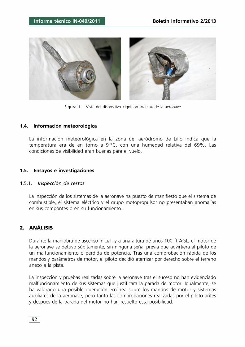
Boletín informativo 2/2013
92
Figura 1. Vista del dispositivo «ignition switch» de la aeronave
1.4. Información meteorológica
La información meteorológica en la zona del aeródromo de Lillo indica que latemperatura era de en torno a 9 °C, con una humedad relativa del 69%. Lascondiciones de visibilidad eran buenas para el vuelo.
1.5. Ensayos e investigaciones
1.5.1. Inspección de restos
La inspección de los sistemas de la aeronave ha puesto de manifiesto que el sistema decombustible, el sistema eléctrico y el grupo motopropulsor no presentaban anomalíasen sus compontes o en su funcionamiento.
2. ANÁLISIS
Durante la maniobra de ascenso inicial, y a una altura de unos 100 ft AGL, el motor dela aeronave se detuvo súbitamente, sin ninguna señal previa que advirtiera al piloto deun malfuncionamiento o perdida de potencia. Tras una comprobación rápida de losmandos y parámetros de motor, el piloto decidió aterrizar por derecho sobre el terrenoanexo a la pista.
La inspección y pruebas realizadas sobre la aeronave tras el suceso no han evidenciadomalfuncionamiento de sus sistemas que justificara la parada de motor. Igualmente, seha valorado una posible operación errónea sobre los mandos de motor y sistemasauxiliares de la aeronave, pero tanto las comprobaciones realizadas por el piloto antesy después de la parada del motor no han resuelto esta posibilidad.
Informe técnico IN-049/2011
2 Emulsión combustible-agua: Una emulsión es una mezcla, más o menos homogénea, de dos fases líquidasinmiscibles, una de las cuales constituye la fase dispersa (agua) y, la otra, la fase continúa (combustible).Dependiendo a las circunstancias a las que se sometan, como: agitación, temperatura, volumen de cada líquido,etc., puede hacerse reversible.
93
Asimismo, se ha considerado la posibilidad de formación de hielo en el carburador, porlas condiciones meteorológicas reinantes y el tiempo en que el motor estuvo rodandoantes de despegar, pero en ningún momento el motor mostró signos de disminución ofalta de potencia.
No obstante, se deben considerar los antecedentes sobre la utilización de la aeronave yde las tareas realizadas previas al vuelo del incidente. Estas muestran que la aeronaveestuvo detenida desde el 14 de julio de 2011 y que, desde entonces, únicamenteefectuó dos vuelos de corta duración. Por otra parte, la preservación durante estetiempo se realizó en un hangar, donde las condiciones climatológicas de la zonaproducen contrastes acusados de temperatura entre el día y la noche. Respecto a lastareas previas al vuelo debe considerarse que, antes de repostar combustible, el depósitoprincipal se encontraba al 50% de su capacidad y el auxiliar vacío, y que su repostajese realizó sin drenar antes el depósito principal.
Las circunstancias referidas anteriormente confirmarían que, antes de producirse elrepostaje, se habría formado agua en el depósito de combustible a consecuencia de lacondensación de la humedad ambiente y que, cuando se repostó hasta completar eldepósito principal, el agua se hubiera emulsionado2 parcialmente con el combustible. Aldrenar posteriormente, la emulsión sería lo suficientemente homogénea como para noapreciarse la presencia del agua y, transcurrido el tiempo en que la aeronave se mantuvoen plataforma, el proceso se invirtió, manifestándose definitivamente durante eldespegue la presencia de agua en el sistema de alimentación, lo que produjo la paradadel motor.
3. CONCLUSIÓN
3.1. Conclusiones
La aeronave disponía de un certificado de aeronavegabilidad en vigor emitido por elestado de matrícula y era mantenida de acuerdo al plan de mantenimiento aprobado.
El piloto disponía de una licencia de vuelo en vigor y las habilitaciones necesarias parael vuelo, incluido el requisito de la competencia lingüística.
No han encontrado evidencias durante la inspección de los sistemas de la aeronave demalfuncionamiento en alguno de ellos.
Informe técnico IN-049/2011Boletín informativo 2/2013
Boletín informativo 2/2013
94
Durante la inspección se observó la instalación de una malla metálica que cubría eldispositivo «ignition switch» que ha dado lugar a la publicación de un boletín de serviciomandatorio por el fabricante, para la corrección de este tipo de instalación.
Se dieron las circunstancias para la presencia de agua en el depósito de combustible(tiempo de parada de la aeronave, variación de temperatura externa y depósitosparcialmente lleno de combustible).
El procedimiento de drenado fue incorrecto, al realizarse posteriormente a repostar.
3.2. Causas
La causa más probable de la parada súbita del motor durante el ascenso inicial fue laingesta de agua en el motor procedente del depósito principal de combustible de laaeronave.
Informe técnico IN-049/2011
ANEXO 1Boletín de servicio N.° 120102
95
Informe técnico IN-049/2011Boletín informativo 2/2013
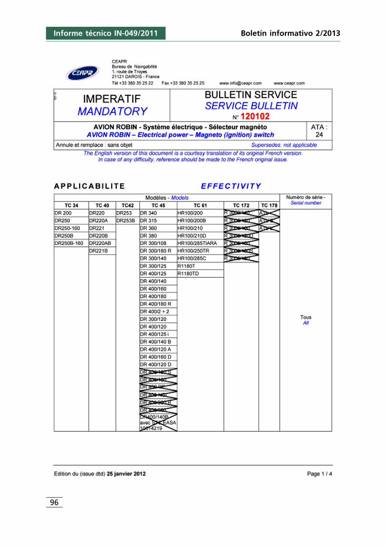
Boletín informativo 2/2013
96
Informe técnico IN-049/2011
97
Informe técnico IN-049/2011Boletín informativo 2/2013
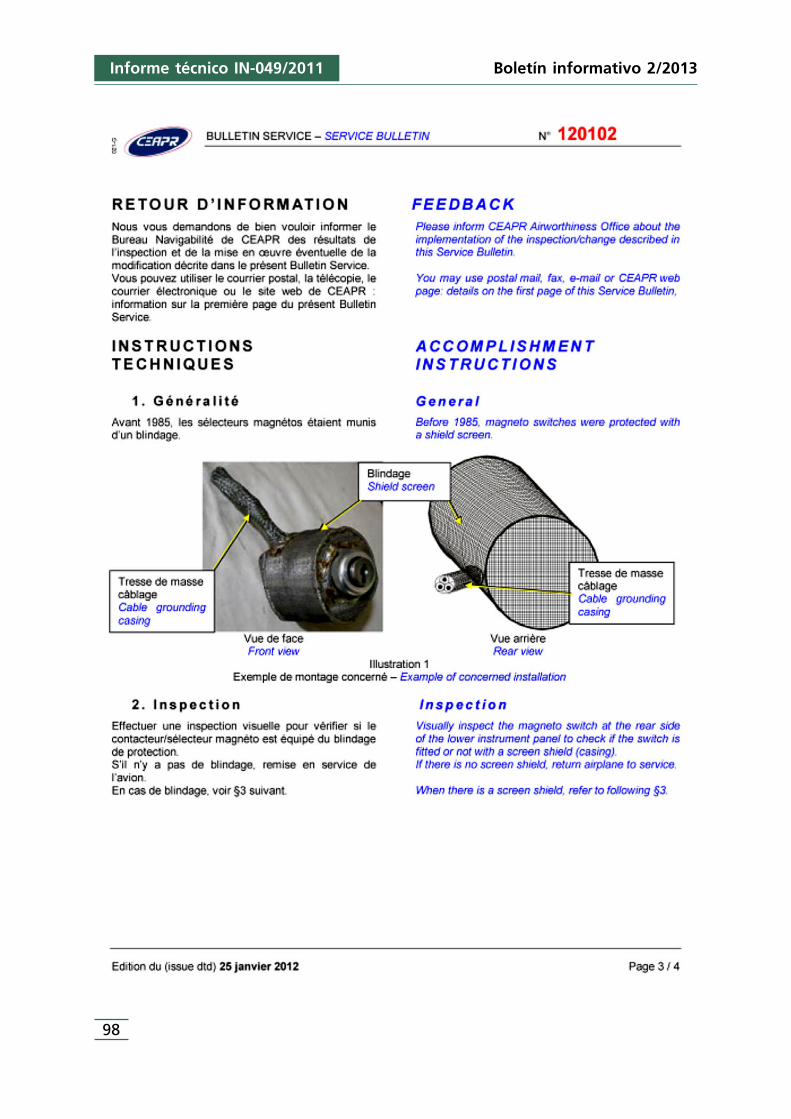
Boletín informativo 2/2013
98
Informe técnico IN-049/2011
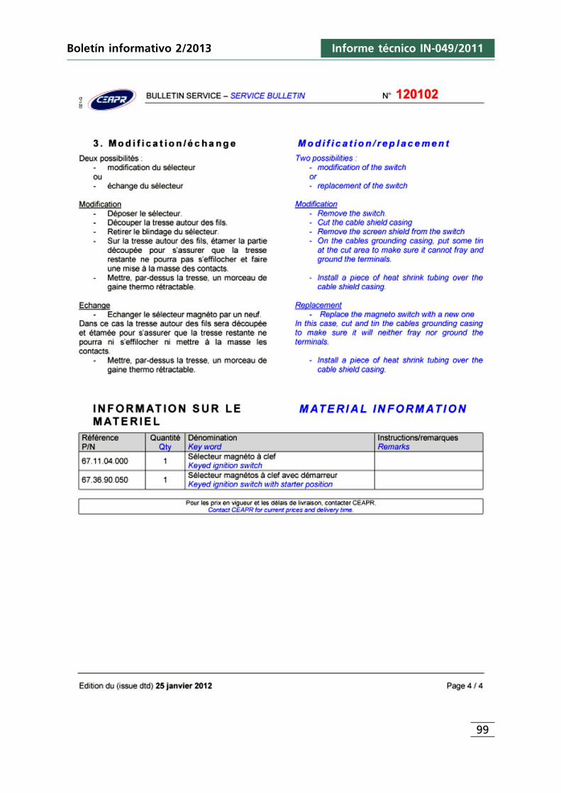
99
Informe técnico IN-049/2011Boletín informativo 2/2013

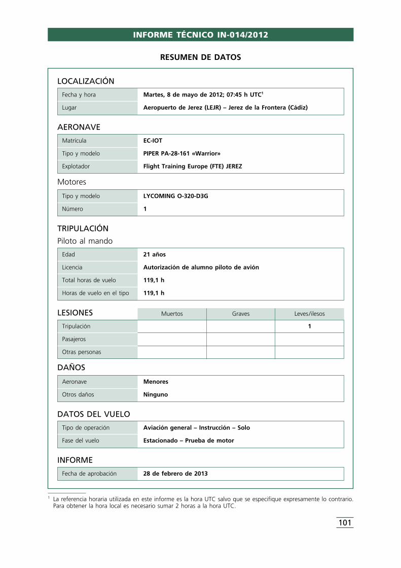
LOCALIZACIÓN
Fecha y hora Martes, 8 de mayo de 2012; 07:45 h UTC1
Lugar Aeropuerto de Jerez (LEJR) – Jerez de la Frontera (Cádiz)
DATOS DEL VUELO
Tipo de operación Aviación general – Instrucción – Solo
Fase del vuelo Estacionado – Prueba de motor
INFORME
Fecha de aprobación 28 de febrero de 2013
TRIPULACIÓN
Piloto al mando
Edad 21 años
Licencia Autorización de alumno piloto de avión
Total horas de vuelo 119,1 h
Horas de vuelo en el tipo 119,1 h
AERONAVE
Matrícula EC-IOT
Tipo y modelo PIPER PA-28-161 «Warrior»
Explotador Flight Training Europe (FTE) JEREZ
Motores
Tipo y modelo LYCOMING O-320-D3G
Número 1
LESIONES Muertos Graves Leves /ilesos
Tripulación 1
Pasajeros
Otras personas
DAÑOS
Aeronave Menores
Otros daños Ninguno
RESUMEN DE DATOS
1 La referencia horaria utilizada en este informe es la hora UTC salvo que se especifique expresamente lo contrario.Para obtener la hora local es necesario sumar 2 horas a la hora UTC.
101
INFORME TÉCNICO IN-014/2012
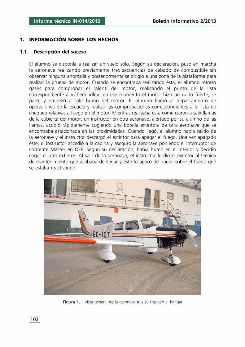
1. INFORMACIÓN SOBRE LOS HECHOS
1.1. Descripción del suceso
El alumno se disponía a realizar un vuelo solo. Según su declaración, puso en marchala aeronave realizando previamente tres secuencias de cebado de combustible sinobservar ninguna anomalía y posteriormente se dirigió a una zona de la plataforma pararealizar la prueba de motor. Cuando se encontraba realizando ésta, el alumno retrasógases para comprobar el ralentí del motor, realizando el punto de la listacorrespondiente a «Check idle»; en ese momento el motor hizo un ruido fuerte, separó, y empezó a salir humo del motor. El alumno llamó al departamento deoperaciones de la escuela y realizó las comprobaciones correspondientes a la lista dechequeo relativas a fuego en el motor. Mientras realizaba ésta comenzaron a salir llamasde la cubierta del motor; un instructor en otra aeronave, alertado por su alumno de lasllamas, acudió rápidamente cogiendo una botella extintora de otra aeronave que seencontraba estacionada en las proximidades. Cuando llegó, el alumno había salido dela aeronave y el instructor descargó el extintor para apagar el fuego. Una vez apagadoéste, el instructor accedió a la cabina y aseguró la aeronave poniendo el interruptor decorriente Master en OFF. Según su declaración, había humo en el interior y decidiócoger el otro extintor. Al salir de la aeronave, el instructor le dio el extintor al técnicode mantenimiento que acababa de llegar y éste lo aplicó de nuevo sobre el fuego quese estaba reactivando.
Figura 1. Vista general de la aeronave tras su traslado al hangar
Informe técnico IN-014/2012
102
Boletín informativo 2/2013
El alumno resultó ileso. La aeronave tuvo daños confinados a la zona del motor y sucarenado, siendo remolcada posteriormente a un hangar y preservada para su posteriorinspección.
1.2. Información sobre la tripulación
El alumno, de nacionalidad jordana y 21 años, contaba con una autorización de alumnopiloto de avión y certificado médico clase 2, ambos válidos y en vigor. Tenía unaexperiencia total en vuelo de 119 horas y 6 minutos, todas ellas en el tipo.
1.3. Información de la aeronave
La aeronave, un modelo Piper PA-28-161 «Warrior», con número de serie S/N 2816046,es un monomotor (Lycoming 0-320-D3G S/N RL-18641-39A) de hélice tripala, planobajo y tren triciclo fijo. Tenía certificado de aeronavegabilidad, matrícula y licencia de estación de aeronave, todos ellos válidos y en vigor. La aeronave contaba con7.063:30 horas totales y el motor con 886 h. El último vuelo correspondiente a un vuelolocal LEJR-LEJR se había realizado el 3 de mayo de 2012. La última inspección de laaeronave (correspondiente a las 50 h) se realizó el día antes del incidente (07/05/2012)sin apreciarse anomalía alguna según los registros del centro de mantenimiento de laEscuela.
1.4. Inspección de la aeronave tras el incidente
En la inspección visual inmediata al incidente se comprobó que el interruptor de labatería estaba en ON, bomba de combustible ON, el tanque de combustibleseleccionado era el derecho, luz rotatoria puesta, gases cerrados, mezcla cortada(«ICO») y la aeronave correctamente estacionada en la barra T. Posteriormente elalumno confirmó que la calefacción al carburador no estaba seleccionada. Según sudeclaración, el alumno había cebado 3 veces el motor antes de arrancarlo y habríafuncionado normalmente hasta su puesta al ralentí.
En la inspección realizada posteriormente a la aeronave en el hangar se observó larotura del conducto de la toma de aire caliente (procedente de los tubos de escape) delcarburador, con signos de haber estado sometido a altas temperaturas. Así mismo laparte inferior del carenado del motor había sido afectada por las altas temperaturas. Seprocedió a comprobar las tuberías de combustible así como la zona del carburador, noencontrando evidencias de una posible pérdida o fugas de combustible. El foco delincendio parecía haberse producido en el recodo del conducto de entrada de airecaliente desde los tubos de escape.
Boletín informativo 2/2013 Informe técnico IN-014/2012
103
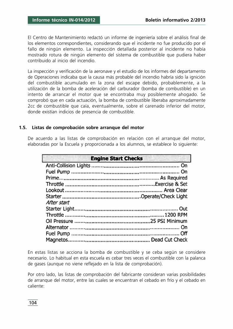
El Centro de Mantenimiento redactó un informe de ingeniería sobre el análisis final delos elementos correspondientes, considerando que el incidente no fue producido por elfallo de ningún elemento. La inspección detallada posterior al incidente no habíamostrado rotura de ningún elemento del sistema de combustible que pudiera habercontribuido al inicio del incendio.
La inspección y verificación de la aeronave y el estudio de los informes del departamentode Operaciones indicaba que la causa más probable del incendio habría sido la ignicióndel combustible acumulado en la zona del escape debido, probablemente, a lautilización de la bomba de aceleración del carburador (bomba de combustible) en unintento de arrancar el motor que se encontraba muy posiblemente ahogado. Secomprobó que en cada actuación, la bomba de combustible liberaba aproximadamente2cc de combustible que caía, eventualmente, sobre el carenado inferior del motor,donde existían indicios de presencia de combustible.
1.5. Listas de comprobación sobre arranque del motor
De acuerdo a las listas de comprobación en relación con el arranque del motor,elaboradas por la Escuela y proporcionada a los alumnos, se establece lo siguiente:
En estas listas se acciona la bomba de combustible y se ceba según se considerenecesario. Lo habitual en esta escuela es cebar tres veces el combustible con la palancade gases (aunque no viene reflejado en la lista de comprobación).
Por otro lado, las listas de comprobación del fabricante consideran varias posibilidadesde arranque del motor, entre las cuales se encuentran el cebado en frío y el cebado encaliente:
Informe técnico IN-014/2012
104
Boletín informativo 2/2013
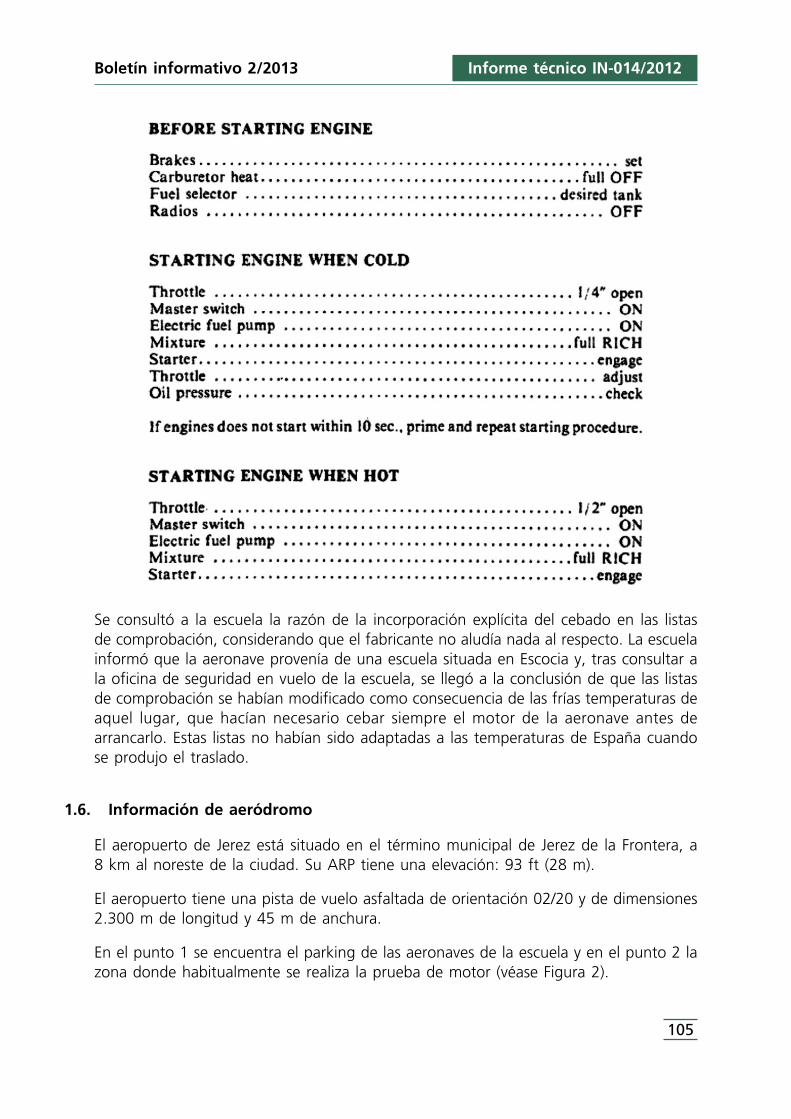
Se consultó a la escuela la razón de la incorporación explícita del cebado en las listasde comprobación, considerando que el fabricante no aludía nada al respecto. La escuelainformó que la aeronave provenía de una escuela situada en Escocia y, tras consultar ala oficina de seguridad en vuelo de la escuela, se llegó a la conclusión de que las listasde comprobación se habían modificado como consecuencia de las frías temperaturas deaquel lugar, que hacían necesario cebar siempre el motor de la aeronave antes dearrancarlo. Estas listas no habían sido adaptadas a las temperaturas de España cuandose produjo el traslado.
1.6. Información de aeródromo
El aeropuerto de Jerez está situado en el término municipal de Jerez de la Frontera, a8 km al noreste de la ciudad. Su ARP tiene una elevación: 93 ft (28 m).
El aeropuerto tiene una pista de vuelo asfaltada de orientación 02/20 y de dimensiones2.300 m de longitud y 45 m de anchura.
En el punto 1 se encuentra el parking de las aeronaves de la escuela y en el punto 2 lazona donde habitualmente se realiza la prueba de motor (véase Figura 2).
Boletín informativo 2/2013 Informe técnico IN-014/2012
105
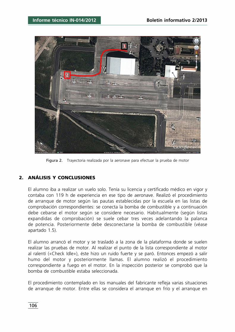
Figura 2. Trayectoria realizada por la aeronave para efectuar la prueba de motor
2. ANÁLISIS Y CONCLUSIONES
El alumno iba a realizar un vuelo solo. Tenía su licencia y certificado médico en vigor ycontaba con 119 h de experiencia en ese tipo de aeronave. Realizó el procedimiento de arranque de motor según las pautas establecidas por la escuela en las listas decomprobación correspondientes: se conecta la bomba de combustible y a continuacióndebe cebarse el motor según se considere necesario. Habitualmente (según listasexpandidas de comprobación) se suele cebar tres veces adelantando la palanca de potencia. Posteriormente debe desconectarse la bomba de combustible (véaseapartado 1.5).
El alumno arrancó el motor y se trasladó a la zona de la plataforma donde se suelenrealizar las pruebas de motor. Al realizar el punto de la lista correspondiente al motoral ralentí («Check Idle»), éste hizo un ruido fuerte y se paró. Entonces empezó a salirhumo del motor y posteriormente llamas. El alumno realizó el procedimientocorrespondiente a fuego en el motor. En la inspección posterior se comprobó que labomba de combustible estaba seleccionada.
El procedimiento contemplado en los manuales del fabricante refleja varias situacionesde arranque de motor. Entre ellas se considera el arranque en frío y el arranque en
Informe técnico IN-014/2012
106
Boletín informativo 2/2013
caliente. En el caso de arranque en frío no se contempla el cebado del motor exceptoen el caso de que éste no arranque en los primeros 10 segundos, caso en el cual sedebe cebar (no se especifica el número de veces, en principio se presupone sólo una) yrepetir el procedimiento de arranque de nuevo.
Con motivo de las diferencias entre listas de comprobación del fabricante y lasproporcionadas por la escuela, se consultó a ésta la razón de la incorporación explícitadel cebado en las listas de comprobación considerando que el fabricante no aludía nadaal respecto. La escuela informó que la aeronave provenía de una escuela de Escocia yal indagar habían confirmado que las listas de comprobación se habían modificadodebido a que las frías temperaturas de aquel lugar impedían el arranque normal sinrealizar el cebado del motor previamente. Estas listas no habían sido adaptadas a lastemperaturas de España cuando se produjo el traslado, manteniéndolas igual. Por estemotivo, le escuela procedió a elaborar una modificación de las listas expandidasadaptándolas de nuevo a las del fabricante, aunque manteniendo en las listas normalesel punto de «Cebado: según se considere» emitiendo una advertencia a las tripulaciones(«Flight Crew Notice», véase Anexo A) sobre las condiciones en las que realizar elcebado. La escuela se comprometió a revisar todas las listas expandidas decomprobación e incorporarlas en el Manual de Operaciones.
Se considera que el incidente ocurrió por un exceso de cebado en el motor, y añadiendoel posible funcionamiento de la bomba de combustible en el momento de las pruebasde motor propiciaron que el exceso de combustible, en contacto con algún puntocaliente, generara el incendio.
Durante la investigación se descubrió que el exceso de cebado en el motor antes delarranque de éste era habitual entre los alumnos de la escuela debido a la utilización delistas de comprobación que así lo establecían. Se comprobó que las listas del fabricanteno recomendaban el cebado por defecto del motor y que la modificación de las listasdel operador se debía al entorno previo de operación de la aeronave (temperaturas másfrías), y que no se habían considerado en el traslado de la aeronave a España.
No se han considerado recomendaciones puesto que se comprobó que el operadorhabía procedido a la modificación de las listas expandidas de comprobación conformeal fabricante, en cuanto al modo de proceder en el cebado de la aeronave antes de suarranque.
Boletín informativo 2/2013 Informe técnico IN-014/2012
107

ANEXO A«Flight Crew Notice»
Boletín informativo 2/2013 Informe técnico IN-014/2012
109
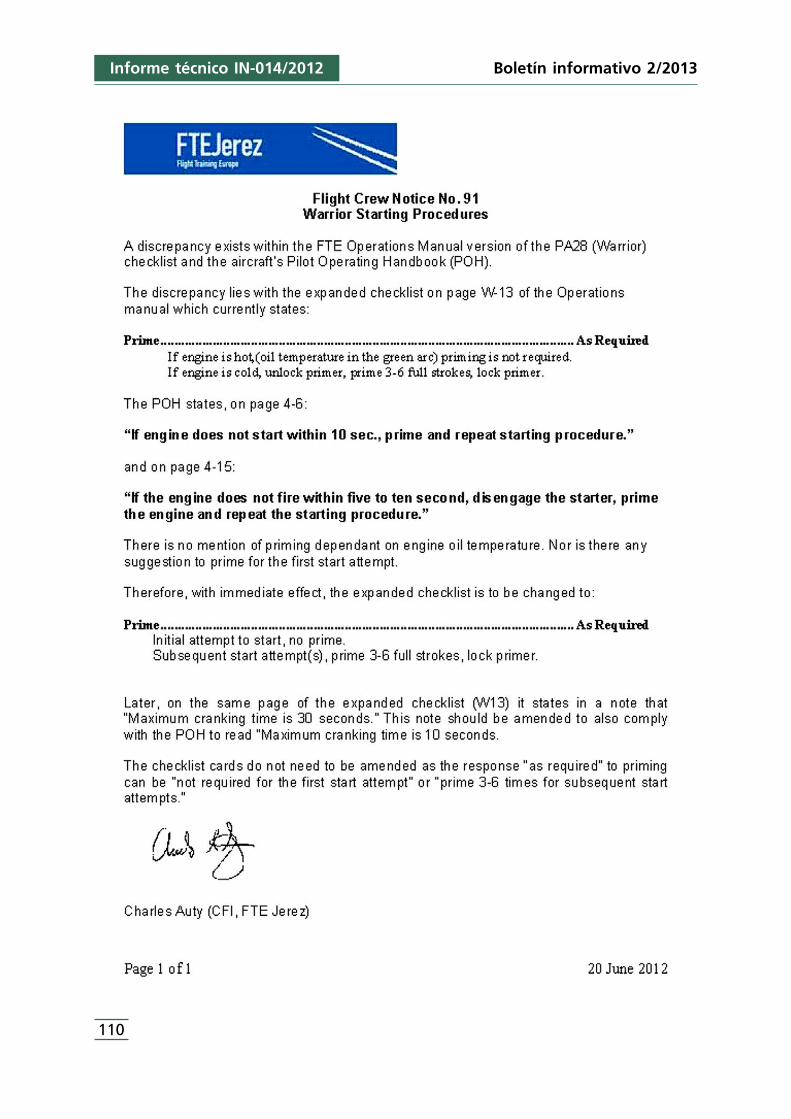
Boletín informativo 2/2013
110
Informe técnico IN-014/2012
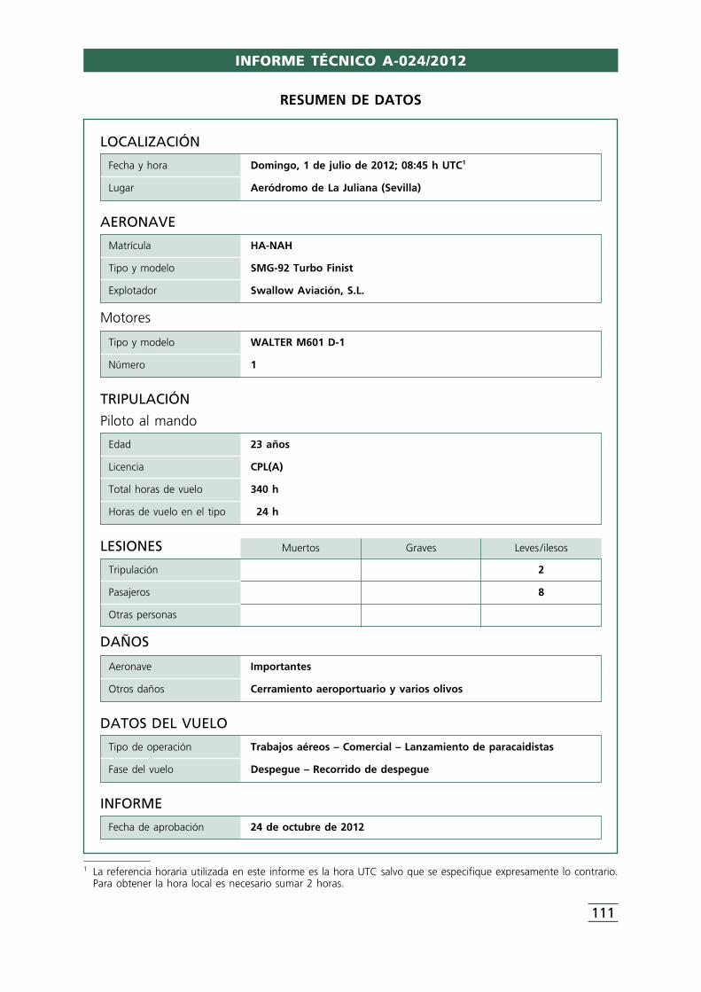
INFORME TÉCNICO A-024/2012
111
LOCALIZACIÓN
Fecha y hora Domingo, 1 de julio de 2012; 08:45 h UTC1
Lugar Aeródromo de La Juliana (Sevilla)
DATOS DEL VUELO
Tipo de operación Trabajos aéreos – Comercial – Lanzamiento de paracaidistas
Fase del vuelo Despegue – Recorrido de despegue
INFORME
Fecha de aprobación 24 de octubre de 2012
TRIPULACIÓN
Piloto al mando
Edad 23 años
Licencia CPL(A)
Total horas de vuelo 340 h
Horas de vuelo en el tipo 24 h
AERONAVE
Matrícula HA-NAH
Tipo y modelo SMG-92 Turbo Finist
Explotador Swallow Aviación, S.L.
Motores
Tipo y modelo WALTER M601 D-1
Número 1
LESIONES Muertos Graves Leves /ilesos
Tripulación 2
Pasajeros 8
Otras personas
DAÑOS
Aeronave Importantes
Otros daños Cerramiento aeroportuario y varios olivos
RESUMEN DE DATOS
1 La referencia horaria utilizada en este informe es la hora UTC salvo que se especifique expresamente lo contrario.Para obtener la hora local es necesario sumar 2 horas.
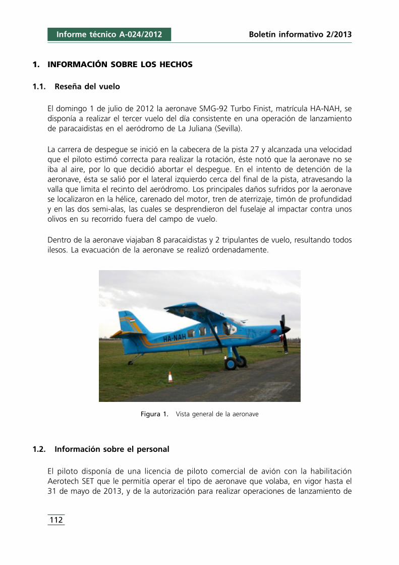
Boletín informativo 2/2013Informe técnico A-024/2012
112
1. INFORMACIÓN SOBRE LOS HECHOS
1.1. Reseña del vuelo
El domingo 1 de julio de 2012 la aeronave SMG-92 Turbo Finist, matrícula HA-NAH, sedisponía a realizar el tercer vuelo del día consistente en una operación de lanzamientode paracaidistas en el aeródromo de La Juliana (Sevilla).
La carrera de despegue se inició en la cabecera de la pista 27 y alcanzada una velocidadque el piloto estimó correcta para realizar la rotación, éste notó que la aeronave no seiba al aire, por lo que decidió abortar el despegue. En el intento de detención de laaeronave, ésta se salió por el lateral izquierdo cerca del final de la pista, atravesando lavalla que limita el recinto del aeródromo. Los principales daños sufridos por la aeronavese localizaron en la hélice, carenado del motor, tren de aterrizaje, timón de profundidady en las dos semi-alas, las cuales se desprendieron del fuselaje al impactar contra unosolivos en su recorrido fuera del campo de vuelo.
Dentro de la aeronave viajaban 8 paracaidistas y 2 tripulantes de vuelo, resultando todosilesos. La evacuación de la aeronave se realizó ordenadamente.
Figura 1. Vista general de la aeronave
1.2. Información sobre el personal
El piloto disponía de una licencia de piloto comercial de avión con la habilitaciónAerotech SET que le permitía operar el tipo de aeronave que volaba, en vigor hasta el31 de mayo de 2013, y de la autorización para realizar operaciones de lanzamiento de
2 PAR: «Dropping of parachutists».3 Distancia de despegue: distancia total disponible para el despegue de un avión hasta que éste alcanza una altura
de 35 ft sobre el terreno.4 Carrera de despegue: longitud de la pista que recorre la aeronave hasta que separa las ruedas del terreno.
Informe técnico A-024/2012Boletín informativo 2/2013
113
paracaidistas (PAR2). Su reconocimiento médico estaba en vigor con validez hasta el 4de enero de 2013.
La actividad aérea de ese día había comenzado a las 07:15 h y había realizado dosvuelos de las mismas características previos al del accidente. En los últimos 30 días elpiloto había volado 12 h y, en los últimos 90 días, 58 h.
En la aeronave volaba también un piloto de seguridad, ya que el piloto al mando seestaba familiarizando con las características del campo.
1.3. Información sobre la aeronave
La aeronave modelo SMG-92 Turbo Finist está equipada con un motor turbohélice,modelo Walter M601 D-1, de hélice tripala y dispone de patín de cola. El peso máximoal despegue es de 2.700 kg en configuración para operaciones de lanzamiento de paracaidistas. Esta aeronave fue fabricada en 1994 con número de serie 003. Lacélula contaba con 2.575 h de vuelo y el motor tenía registradas 1.556 h defuncionamiento.
La documentación de la aeronave estaba en vigor en la fecha en la que ocurrió elaccidente.
La última revisión de mantenimiento realizada a la aeronave fue el 22 de mayo de 2012y correspondió a una inspección de 500 horas, acorde al programa de mantenimiento.
Por otra parte, en la Sección 9 del Manual de vuelo se trata el tema sobre las diferenciasque debe de tener en cuenta el piloto a la hora de realizar operaciones de lanzamientode paracaidistas con esta aeronave, ya que en este tipo de operación se permiteaumentar el peso máximo al despegue hasta 2.700 kg (en operación normal el pesomáximo al despegue es de 2.350 kg).
Este aumento de peso hace que aumenten también la distancia de despegue y deaterrizaje necesarias, así como la velocidad de rotación, siendo esta última 86 kt conflap 0° y 79 kt con flap 20°.
Según las tablas de performances de la aeronave, con las condiciones existentes en elaeródromo, la distancia de despegue3 sería de 600 m y la carrera de despegue4 sería de340 m aproximadamente.
Boletín informativo 2/2013Informe técnico A-024/2012
114
A continuación se recoge la carga y centrado de la aeronave antes del vuelo:
Weight Arm Aft Datum MomentHA-NAH
(kg) (m) (kg · m)
Peso básico en vacío 1.509 1,425 2.150,00
Piloto y copiloto 150 0,951 142,65
Paracaidistas 3 & 10 160 1,770 283,20
Paracaidistas 4 & 9 160 2,280 364,80
Paracaidistas 5 & 8 160 2,840 454,40
Paracaidistas 6 & 7 160 3,330 532,80
Peso con combustible cero 2.299 1,708 3.927,85
Combustible (0,8 kg/l) 192 1,250 240,00
Peso en rampa (máx. 2.700 kg) 2.491 1,664 4.167,85
Arranque y rodaje –10 1,250 –12,50
Peso al despegue (máx. 2.700/2.350 kg) 2.481 1,675 4.155,35
El Manual establece el límite delantero en 1,330 m y el límite trasero en 1,680 m. Elresultado del cálculo de la carga y centrado (1,675 m) demuestra que el centro degravedad estaba muy retrasado, pero dentro de límites.
En el apartado 4 del mencionado Manual de vuelo, referente a emergencias,recomienda en caso de abortar el despegue:
a) Palanca de gases en IDLE.b) Palanca de gases en BETA y reversa.c) Frenar.d) Librando pista parar el motor si fuera necesario y evacuar la aeronave.
La palanca selectora de flap está situada en el pedestal central y tiene tres posiciones:arriba (up), despegue (take-off 20°) y aterrizaje (full down 40°). A la izquierda del panelde instrumentos hay un indicador luminoso de posición de flap. Cuando el flap seencuentra en tránsito se ilumina con tres luces amarillas. Cuando el flap está fijo en lasposiciones de despegue o aterrizaje se ilumina con tres luces verdes. Cuando el flap estáretraído en posición arriba no hay ninguna indicación.
1.4. Información meteorológica
La situación meteorológica más probable durante el despegue fue de viento de direcciónvariable entre 340° y 010° con una intensidad entre 6 y 11 km/h y racha máxima entre
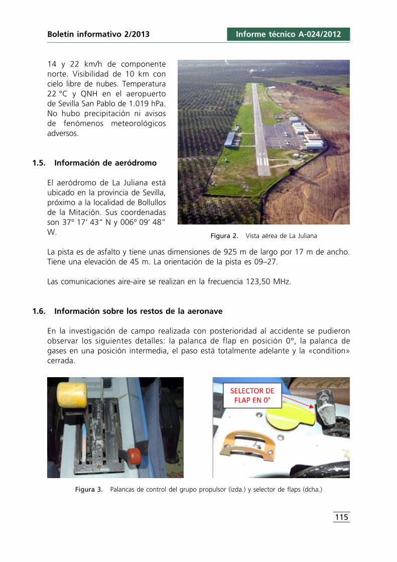
14 y 22 km/h de componentenorte. Visibilidad de 10 km concielo libre de nubes. Temperatura22 °C y QNH en el aeropuerto de Sevilla San Pablo de 1.019 hPa.No hubo precipitación ni avisos de fenómenos meteorológicosadversos.
1.5. Información de aeródromo
El aeródromo de La Juliana estáubicado en la provincia de Sevilla,próximo a la localidad de Bollullosde la Mitación. Sus coordenadasson 37° 17’ 43” N y 006° 09’ 48”W.
La pista es de asfalto y tiene unas dimensiones de 925 m de largo por 17 m de ancho.Tiene una elevación de 45 m. La orientación de la pista es 09–27.
Las comunicaciones aire-aire se realizan en la frecuencia 123,50 MHz.
1.6. Información sobre los restos de la aeronave
En la investigación de campo realizada con posterioridad al accidente se pudieronobservar los siguientes detalles: la palanca de flap en posición 0°, la palanca de gases en una posición intermedia, el paso está totalmente adelante y la «condition»cerrada.
Figura 3. Palancas de control del grupo propulsor (izda.) y selector de flaps (dcha.)
Figura 2. Vista aérea de La Juliana
Informe técnico A-024/2012Boletín informativo 2/2013
115
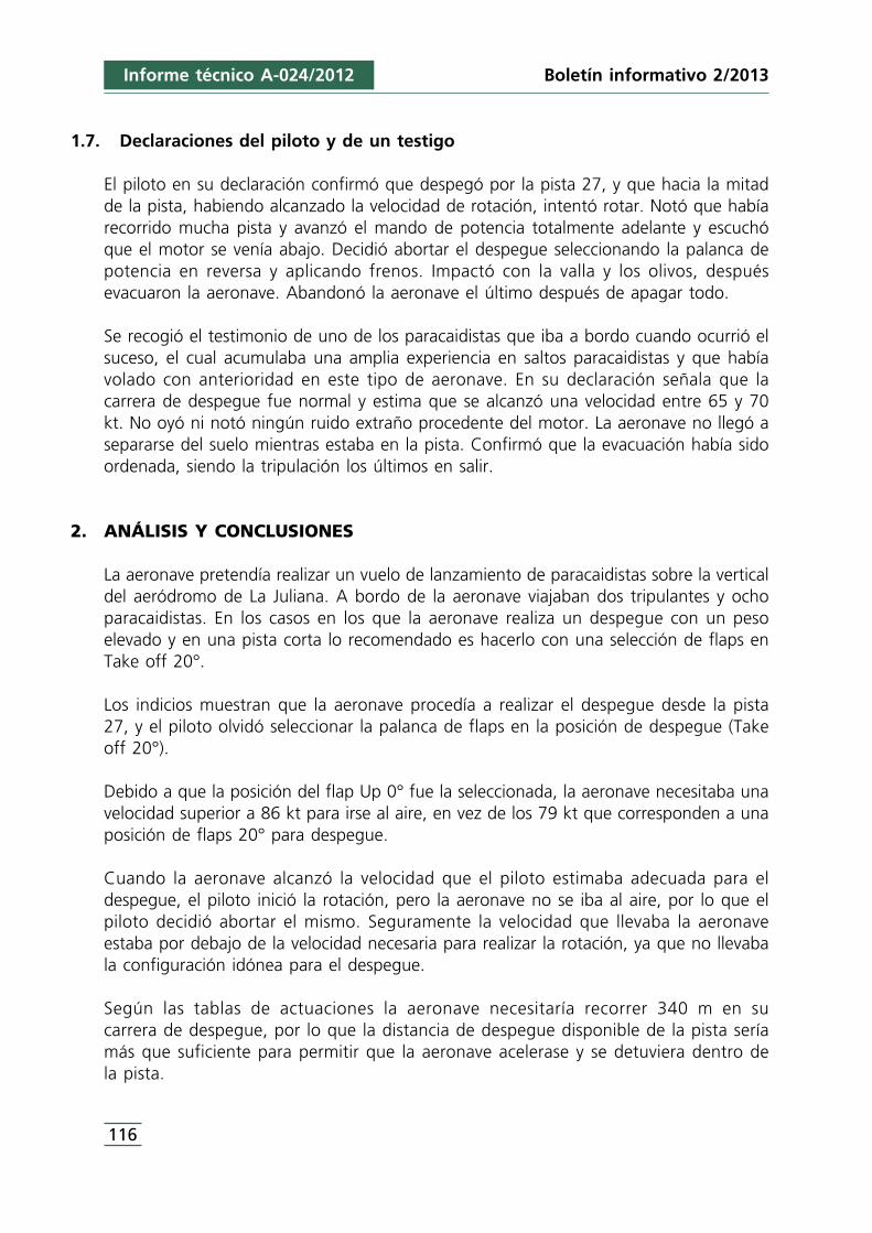
1.7. Declaraciones del piloto y de un testigo
El piloto en su declaración confirmó que despegó por la pista 27, y que hacia la mitadde la pista, habiendo alcanzado la velocidad de rotación, intentó rotar. Notó que habíarecorrido mucha pista y avanzó el mando de potencia totalmente adelante y escuchóque el motor se venía abajo. Decidió abortar el despegue seleccionando la palanca depotencia en reversa y aplicando frenos. Impactó con la valla y los olivos, despuésevacuaron la aeronave. Abandonó la aeronave el último después de apagar todo.
Se recogió el testimonio de uno de los paracaidistas que iba a bordo cuando ocurrió elsuceso, el cual acumulaba una amplia experiencia en saltos paracaidistas y que habíavolado con anterioridad en este tipo de aeronave. En su declaración señala que lacarrera de despegue fue normal y estima que se alcanzó una velocidad entre 65 y 70kt. No oyó ni notó ningún ruido extraño procedente del motor. La aeronave no llegó asepararse del suelo mientras estaba en la pista. Confirmó que la evacuación había sidoordenada, siendo la tripulación los últimos en salir.
2. ANÁLISIS Y CONCLUSIONES
La aeronave pretendía realizar un vuelo de lanzamiento de paracaidistas sobre la verticaldel aeródromo de La Juliana. A bordo de la aeronave viajaban dos tripulantes y ochoparacaidistas. En los casos en los que la aeronave realiza un despegue con un pesoelevado y en una pista corta lo recomendado es hacerlo con una selección de flaps enTake off 20°.
Los indicios muestran que la aeronave procedía a realizar el despegue desde la pista27, y el piloto olvidó seleccionar la palanca de flaps en la posición de despegue (Takeoff 20°).
Debido a que la posición del flap Up 0° fue la seleccionada, la aeronave necesitaba unavelocidad superior a 86 kt para irse al aire, en vez de los 79 kt que corresponden a unaposición de flaps 20° para despegue.
Cuando la aeronave alcanzó la velocidad que el piloto estimaba adecuada para eldespegue, el piloto inició la rotación, pero la aeronave no se iba al aire, por lo que elpiloto decidió abortar el mismo. Seguramente la velocidad que llevaba la aeronaveestaba por debajo de la velocidad necesaria para realizar la rotación, ya que no llevabala configuración idónea para el despegue.
Según las tablas de actuaciones la aeronave necesitaría recorrer 340 m en su carrera de despegue, por lo que la distancia de despegue disponible de la pista seríamás que suficiente para permitir que la aeronave acelerase y se detuviera dentro dela pista.
116
Informe técnico A-024/2012 Boletín informativo 2/2013
117
Boletín informativo 2/2013 Informe técnico A-024/2012
El piloto, al actuar los frenos, posiblemente lo hizo de forma asimétrica, lo que le llevóa sacar la aeronave por el lado izquierdo de la pista, y la distancia que recorrió laaeronave hasta detenerse hace pensar que el piloto no actuó correctamente sobre lareversa, cuya acción conjunta con la de los frenos le hubiera permitido detener laaeronave en una distancia mucho menor.
Se estima que el accidente se produjo debido a que la aeronave no estaba en unaconfiguración de flaps correcta para realizar el despegue. Ello provocó que el piloto, alalcanzar la velocidad que él estimaba necesaria en configuración de flap de despeguepara la rotación y no irse la aeronave al aire, decidiese abortar el mismo. Por otra parte,una incorrecta actuación sobre los frenos y la reversa le llevaron primero a salirse de lapista, y posteriormente a impactar contra la valla del aeródromo y los olivos del terreno.

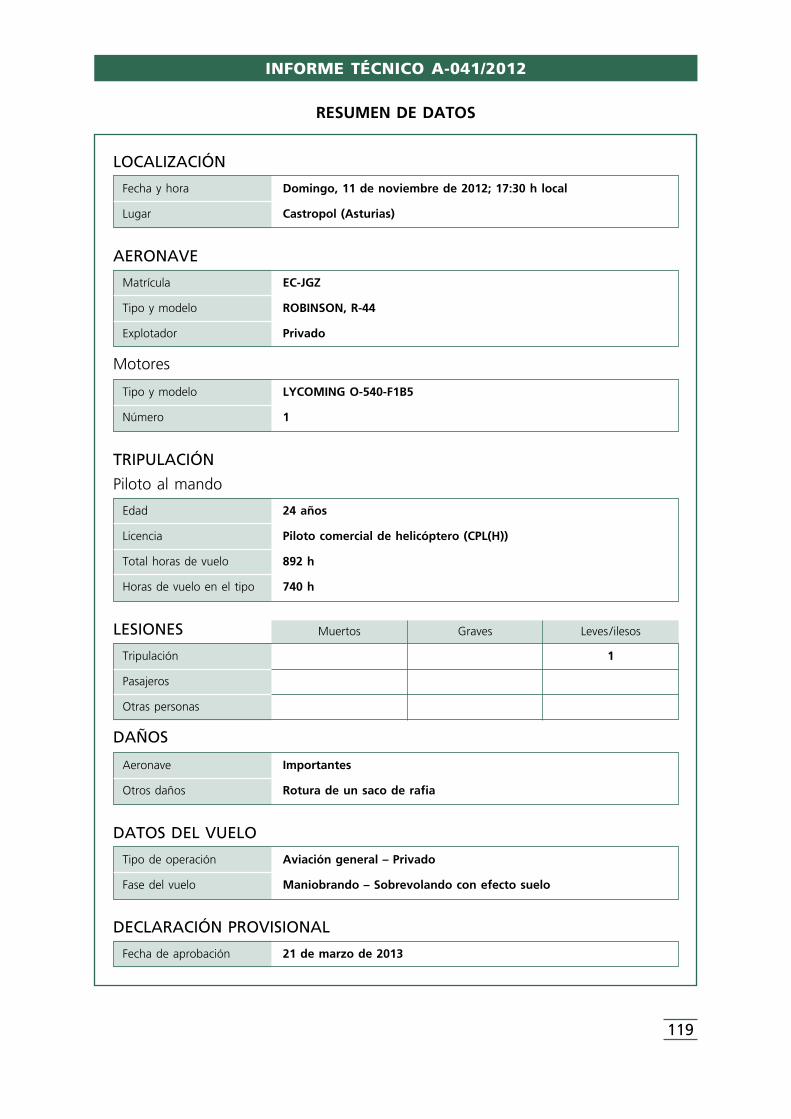
INFORME TÉCNICO A-041/2012
119
LOCALIZACIÓN
Fecha y hora Domingo, 11 de noviembre de 2012; 17:30 h local
Lugar Castropol (Asturias)
DATOS DEL VUELO
Tipo de operación Aviación general – Privado
Fase del vuelo Maniobrando – Sobrevolando con efecto suelo
DECLARACIÓN PROVISIONAL
Fecha de aprobación 21 de marzo de 2013
TRIPULACIÓN
Piloto al mando
Edad 24 años
Licencia Piloto comercial de helicóptero (CPL(H))
Total horas de vuelo 892 h
Horas de vuelo en el tipo 740 h
AERONAVE
Matrícula EC-JGZ
Tipo y modelo ROBINSON, R-44
Explotador Privado
Motores
Tipo y modelo LYCOMING O-540-F1B5
Número 1
LESIONES Muertos Graves Leves /ilesos
Tripulación 1
Pasajeros
Otras personas
DAÑOS
Aeronave Importantes
Otros daños Rotura de un saco de rafia
RESUMEN DE DATOS
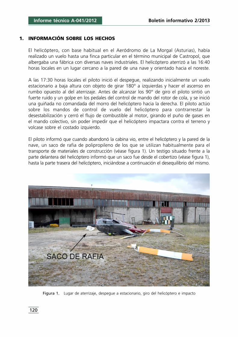
Boletín informativo 2/2013Informe técnico A-041/2012
120
1. INFORMACIÓN SOBRE LOS HECHOS
El helicóptero, con base habitual en el Aeródromo de La Morgal (Asturias), habíarealizado un vuelo hasta una finca particular en el término municipal de Castropol, quealbergaba una fábrica con diversas naves industriales. El helicóptero aterrizó a las 16:40horas locales en un lugar cercano a la pared de una nave y orientado hacia el noreste.
A las 17:30 horas locales el piloto inició el despegue, realizando inicialmente un vueloestacionario a baja altura con objeto de girar 180° a izquierdas y hacer el ascenso enrumbo opuesto al del aterrizaje. Antes de alcanzar los 90° de giro el piloto sintió unfuerte ruido y un golpe en los pedales del control de mando del rotor de cola, y se inicióuna guiñada no comandada del morro del helicóptero hacia la derecha. El piloto actúosobre los mandos de control de vuelo del helicóptero para contrarrestar ladesestabilización y cerró el flujo de combustible al motor, girando el puño de gases enel mando colectivo, sin poder impedir que el helicóptero impactara contra el terreno yvolcase sobre el costado izquierdo.
El piloto informó que cuando abandonó la cabina vio, entre el helicóptero y la pared de lanave, un saco de rafia de polipropileno de los que se utilizan habitualmente para eltransporte de materiales de construcción (véase figura 1). Un testigo situado frente a laparte delantera del helicóptero informó que un saco fue desde el cobertizo (véase figura 1),hasta la parte trasera del helicóptero, iniciándose a continuación el desequilibrio del mismo.
Figura 1. Lugar de aterrizaje, despegue a estacionario, giro del helicóptero e impacto
El helicóptero presentaba daños importantes en el rotor principal, en la transmisión depotencia al rotor principal, en el fuselaje, en el cono de cola y el eje de transmisión depotencia al rotor de cola presentaba una rotura por torsión. Las palas del rotor de colano presentaban impactos severos y en las puntas de las palas se hallaron fibras de rafiade polipropileno. El saco se halló roto.
El helicóptero modelo Robinson R-44 con matrícula EC-JGZ y número de serie 0965tenía un total de 1.331 h de vuelo, era mantenido de acuerdo al programa aprobado,habiendo sido efectuada la última revisión (correspondiente a la de 50 h) a las 1.300 hde vuelo del helicóptero. El giro del rotor principal es antihorario observando el rotordesde arriba. El flujo de aire que origina el rotor de cola va desde el costado derechohacia el costado izquierdo del helicóptero.
El manual de vuelo reseña que una pérdida de empuje del rotor de cola en estacionarioes normalmente indicada por una guiñada a la derecha que no puede ser corregidaaplicando pedal izquierdo, y se requiere actuar inmediatamente girando el puño degases para cerrar el flujo de combustible al motor al objeto de detener la guiñada yfinalmente ajustar el colectivo para acolchar la toma.
El piloto tenía autorización para aterrizar y despegar en la finca y había aterrizado dosveces con anterioridad, siendo la primera vez el 25 de octubre del 2012 y la última eldía del accidente. Había aterrizado en la misma zona que las veces anteriores, cercanaal cobertizo que se ve en la figura 1, sin apreciar elementos que pudieran ser levantadosy atraídos por el flujo de aire del helicóptero.
2. ANÁLISIS Y CONCLUSIONES
El giro del helicóptero sobre su eje vertical, comandado por el piloto, desplazó el morrodel helicóptero hacia la izquierda y aproximó la cola del mismo hacia el cobertizo,momento en el que el testigo observó como el saco de rafia de polipropileno volabahacia la parte trasera del helicóptero.
El saco pudo ser succionado por el flujo de aire producido por el rotor de cola cuandoéste se aproximó a la zona del cobertizo. Las hebras de rafia de polipropileno halladasen las puntas de las palas del rotor de cola son compatibles con el enganche del sacoen el conjunto del rotor de cola.
Los sacos de rafia de polipropileno, utilizados para el transporte de elementos deconstrucción, precisamente por su volumen y poco peso, son fácilmente succionadospor el flujo producido por los rotores de cola de los helicópteros1.
Informe técnico A-041/2012Boletín informativo 2/2013
121
1 CIAIAC:_IN-005/2010. http://www.fomento.gob.es/NR/rdonlyres/33725BFC-920A-4EC3-ADCA-A36D4DD6F5E0/101821/2010_005_IN.pdf.
La no presencia de impactos severos en las palas del rotor de cola descarta la posibilidadde una detención instantánea de las mismas por impacto contra el suelo mientras elrotor de cola giraba con potencia.
Se considera causa principal del accidente la rotura del eje de potencia al rotor de colapor un sobre-esfuerzo de torsión, al detener momentáneamente el giro del rotor decola la acción del saco de rafia de polipropileno enganchado en dicho rotor. Seconsidera factor contribuyente la no detección por parte del piloto del saco como unobjeto susceptible de ser succionado por el flujo de aire del rotor de cola.
122
Informe técnico A-041/2012 Boletín informativo 2/2013
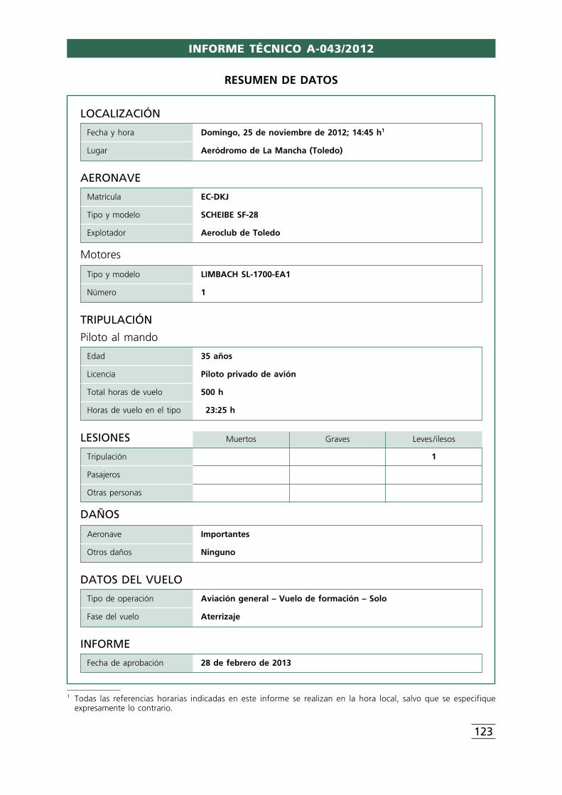
LOCALIZACIÓN
Fecha y hora Domingo, 25 de noviembre de 2012; 14:45 h1
Lugar Aeródromo de La Mancha (Toledo)
DATOS DEL VUELO
Tipo de operación Aviación general – Vuelo de formación – Solo
Fase del vuelo Aterrizaje
INFORME
Fecha de aprobación 28 de febrero de 2013
TRIPULACIÓN
Piloto al mando
Edad 35 años
Licencia Piloto privado de avión
Total horas de vuelo 500 h
Horas de vuelo en el tipo 23:25 h
AERONAVE
Matrícula EC-DKJ
Tipo y modelo SCHEIBE SF-28
Explotador Aeroclub de Toledo
Motores
Tipo y modelo LIMBACH SL-1700-EA1
Número 1
LESIONES Muertos Graves Leves /ilesos
Tripulación 1
Pasajeros
Otras personas
DAÑOS
Aeronave Importantes
Otros daños Ninguno
RESUMEN DE DATOS
1 Todas las referencias horarias indicadas en este informe se realizan en la hora local, salvo que se especifiqueexpresamente lo contrario.
INFORME TÉCNICO A-043/2012
123
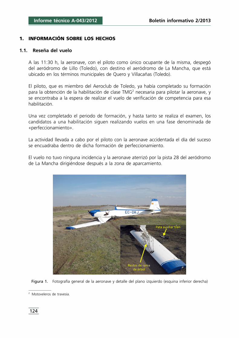
2 Motoveleros de travesía.
Informe técnico A-043/2012
1. INFORMACIÓN SOBRE LOS HECHOS
1.1. Reseña del vuelo
A las 11:30 h, la aeronave, con el piloto como único ocupante de la misma, despegódel aeródromo de Lillo (Toledo), con destino el aeródromo de La Mancha, que estáubicado en los términos municipales de Quero y Villacañas (Toledo).
El piloto, que es miembro del Aeroclub de Toledo, ya había completado su formaciónpara la obtención de la habilitación de clase TMG2 necesaria para pilotar la aeronave, yse encontraba a la espera de realizar el vuelo de verificación de competencia para esahabilitación.
Una vez completado el periodo de formación, y hasta tanto se realiza el examen, loscandidatos a una habilitación siguen realizando vuelos en una fase denominada de«perfeccionamiento».
La actividad llevada a cabo por el piloto con la aeronave accidentada el día del sucesose encuadraba dentro de dicha formación de perfeccionamiento.
El vuelo no tuvo ninguna incidencia y la aeronave aterrizó por la pista 28 del aeródromode La Mancha dirigiéndose después a la zona de aparcamiento.
Figura 1. Fotografía general de la aeronave y detalle del plano izquierdo (esquina inferior derecha)
124
Boletín informativo 2/2013
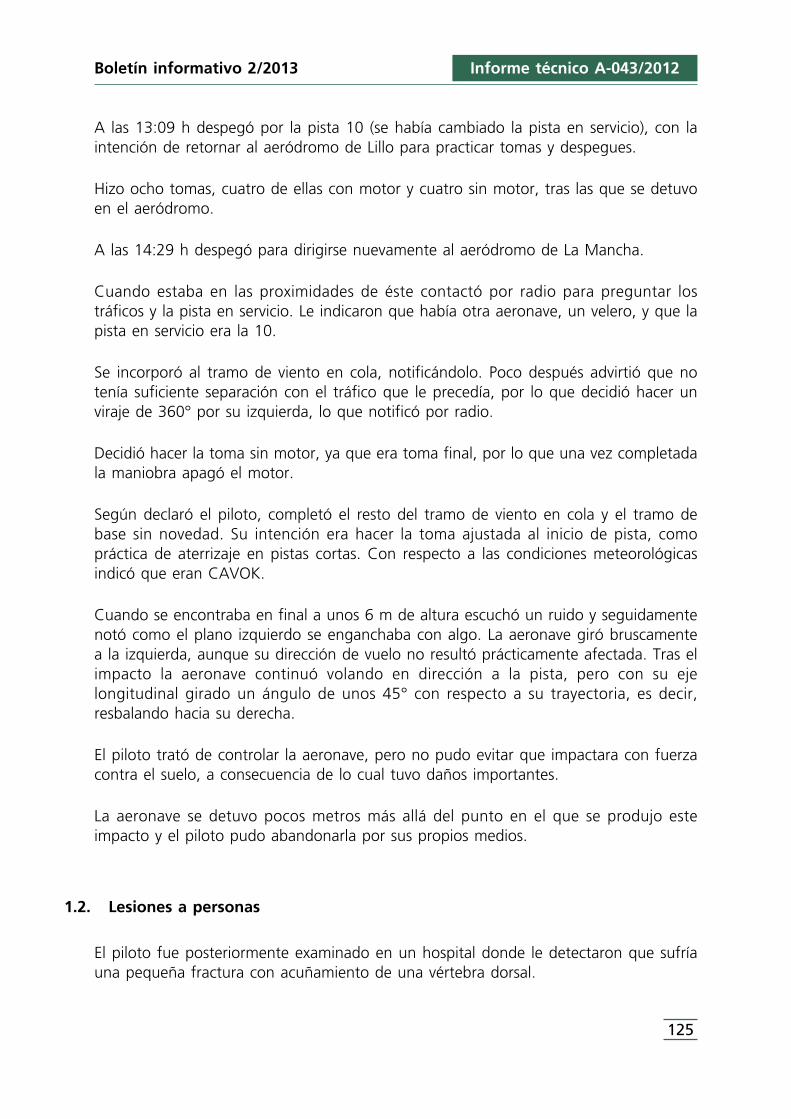
Boletín informativo 2/2013 Informe técnico A-043/2012
A las 13:09 h despegó por la pista 10 (se había cambiado la pista en servicio), con laintención de retornar al aeródromo de Lillo para practicar tomas y despegues.
Hizo ocho tomas, cuatro de ellas con motor y cuatro sin motor, tras las que se detuvoen el aeródromo.
A las 14:29 h despegó para dirigirse nuevamente al aeródromo de La Mancha.
Cuando estaba en las proximidades de éste contactó por radio para preguntar lostráficos y la pista en servicio. Le indicaron que había otra aeronave, un velero, y que lapista en servicio era la 10.
Se incorporó al tramo de viento en cola, notificándolo. Poco después advirtió que notenía suficiente separación con el tráfico que le precedía, por lo que decidió hacer unviraje de 360° por su izquierda, lo que notificó por radio.
Decidió hacer la toma sin motor, ya que era toma final, por lo que una vez completadala maniobra apagó el motor.
Según declaró el piloto, completó el resto del tramo de viento en cola y el tramo debase sin novedad. Su intención era hacer la toma ajustada al inicio de pista, comopráctica de aterrizaje en pistas cortas. Con respecto a las condiciones meteorológicasindicó que eran CAVOK.
Cuando se encontraba en final a unos 6 m de altura escuchó un ruido y seguidamentenotó como el plano izquierdo se enganchaba con algo. La aeronave giró bruscamentea la izquierda, aunque su dirección de vuelo no resultó prácticamente afectada. Tras elimpacto la aeronave continuó volando en dirección a la pista, pero con su ejelongitudinal girado un ángulo de unos 45° con respecto a su trayectoria, es decir,resbalando hacia su derecha.
El piloto trató de controlar la aeronave, pero no pudo evitar que impactara con fuerzacontra el suelo, a consecuencia de lo cual tuvo daños importantes.
La aeronave se detuvo pocos metros más allá del punto en el que se produjo esteimpacto y el piloto pudo abandonarla por sus propios medios.
1.2. Lesiones a personas
El piloto fue posteriormente examinado en un hospital donde le detectaron que sufríauna pequeña fractura con acuñamiento de una vértebra dorsal.
125

Informe técnico A-043/2012
1.3. Daños sufridos por la aeronave
Debido a los impactos con los árboles y luego con el terreno, la aeronave sufrió dañosde importancia que le afectaron fundamentalmente a los siguientes elementos:
• Tren de aterrizaje principal. Colapsado hacia el interior del fuselaje.• Rotura del plano izquierdo a la altura del aerofreno, así como daños en borde de
ataque por impacto con ramas.• Desprendimiento de la pata auxiliar izquierda del tren de aterrizaje.• Deformación del anclaje de la pata de tren auxiliar del plano derecho.
1.4. Información sobre el personal
El piloto disponía de licencias de piloto privado de avión (PPL-A), válida hasta el 30-01-2013, de piloto de planeador (TGLI), válida hasta el 12-04-2014, y de piloto deUltraligeros, válida hasta el 18-01-2015, así como de certificado médico de clase 2 convalidez hasta el 10-11-2014.
Su experiencia de vuelo alcanzaba un total de 500 h, de las cuales 23:25 h las habíarealizado en el tipo de aeronave del accidente.
Había completado la fase de formación para la obtención de la habilitación de claseTMG necesaria para pilotar la aeronave del accidente, encontrándose a la espera derealizar el vuelo de verificación de competencia para esa habilitación.
1.5. Información sobre la aeronave
La aeronave accidentada pertenece al modelo «Scheibe SF-28A Tándem Falke», que esun motovelero biplaza y que está equipado con un motor Limbach SL-1700-EA1. Elavión accidentado fue fabricado por la compañía Scheibe Flugzeugbau GmbH en el año1980, con el número de serie 57114.
El tren de aterrizaje de la aeronave está formado por un tren principal que está situadopor debajo del fuselaje a la altura del asiento delantero de cabina, por dos patasauxiliares ubicadas bajo cada uno de los planos y un patín de cola. El tren principal esdel tipo monorueda y está parcialmente alojado dentro del fuselaje, de forma que desdeel exterior sólo es visible parte de la rueda.
Disponía de certificado de revisión de la aeronavegabilidad, emitido el 28/11/2011, convalidez hasta el 27/11/2012.
En el momento del accidente la célula contaba con 974:42 horas de vuelo y el motorcon 772:49 h.
126
Boletín informativo 2/2013
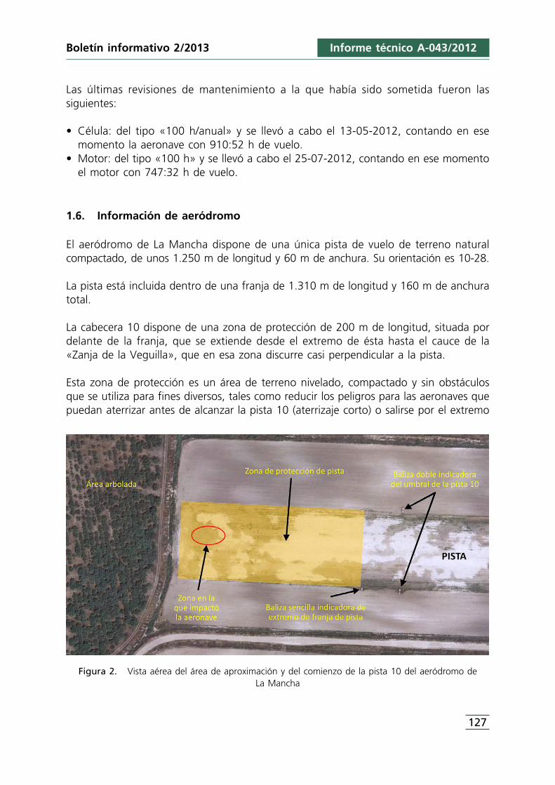
Boletín informativo 2/2013 Informe técnico A-043/2012
Las últimas revisiones de mantenimiento a la que había sido sometida fueron lassiguientes:
• Célula: del tipo «100 h/anual» y se llevó a cabo el 13-05-2012, contando en esemomento la aeronave con 910:52 h de vuelo.
• Motor: del tipo «100 h» y se llevó a cabo el 25-07-2012, contando en ese momentoel motor con 747:32 h de vuelo.
1.6. Información de aeródromo
El aeródromo de La Mancha dispone de una única pista de vuelo de terreno naturalcompactado, de unos 1.250 m de longitud y 60 m de anchura. Su orientación es 10-28.
La pista está incluida dentro de una franja de 1.310 m de longitud y 160 m de anchuratotal.
La cabecera 10 dispone de una zona de protección de 200 m de longitud, situada pordelante de la franja, que se extiende desde el extremo de ésta hasta el cauce de la«Zanja de la Veguilla», que en esa zona discurre casi perpendicular a la pista.
Esta zona de protección es un área de terreno nivelado, compactado y sin obstáculosque se utiliza para fines diversos, tales como reducir los peligros para las aeronaves quepuedan aterrizar antes de alcanzar la pista 10 (aterrizaje corto) o salirse por el extremo
Figura 2. Vista aérea del área de aproximación y del comienzo de la pista 10 del aeródromo deLa Mancha
127
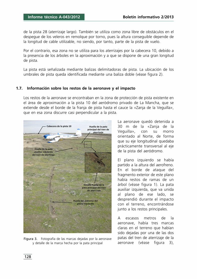
de la pista 28 (aterrizaje largo). También se utiliza como zona libre de obstáculos en eldespegue de los veleros en remolque por torno, pues la altura conseguible depende dela longitud de cable utilizable, no siendo, por tanto, parte de la pista de vuelo.
Por el contrario, esa zona no se utiliza para los aterrizajes por la cabecera 10, debido ala presencia de los árboles en la aproximación y a que se dispone de una gran longitudde pista.
La pista está señalizada mediante balizas delimitadoras de pista. La ubicación de losumbrales de pista queda identificada mediante una baliza doble (véase figura 2).
1.7. Información sobre los restos de la aeronave y el impacto
Los restos de la aeronave se encontraban en la zona de protección de pista existente enel área de aproximación a la pista 10 del aeródromo privado de La Mancha, que seextiende desde el borde de la franja de pista hasta el cauce la «Zanja de la Veguilla»,que en esa zona discurre casi perpendicular a la pista.
La aeronave quedó detenida a30 m de la «Zanja de laVeguilla», con su morroorientado al Norte, de formaque su eje longitudinal quedabaprácticamente transversal al ejede la pista del aeródromo.
El plano izquierdo se habíapartido a la altura del aerofreno.En el borde de ataque delfragmento exterior de este planohabía restos de ramas de unárbol (véase figura 1). La pataauxiliar izquierda, que va unidaal plano de ese lado, sedesprendió durante el impactocon el terreno, encontrándosejunto a los restos principales.
A escasos metros de laaeronave, había tres marcasclaras en el terreno que habíansido dejadas por una de las dospatas del tren de aterrizaje de laaeronave (véase figura 3),
Figura 3. Fotografía de las marcas dejadas por la aeronavey detalle de la marca hecha por la pata principal
Boletín informativo 2/2013
128
Informe técnico A-043/2012
129
concretamente la auxiliar izquierda, por el tren principal y por el extremo del planoizquierdo.
La marca que comenzaba primero, vista en el sentido de la aproximación, era la dejadapor el extremo del plano izquierdo. Esta marca acaba poco antes de que aparezca lamarca dejada por la pata auxiliar izquierda del tren de aterrizaje, que es de escasalongitud.
El contacto del tren principal fue violento, como se desprende de la profundidad de lamarca dejada por éste (véase figura 3). Esta marca ya es contínua hasta el lugar dondequedó detenida la aeronave.
Las huellas dejadas por el extremo del plano izquierdo y por el tren principal forman unángulo de unos 25°.
El terreno situado al otro lado de la «Zanja de la Veguilla» está ocupado por un bosquede pequeñas dimensiones.
Uno de los árboles, que estaba situado en el borde de la «Zanja», mostraba signos dehaber sufrido la rotura de una de sus ramas.
2. ANÁLISIS
Durante la aproximación a la pista 10 del aeródromo de La Mancha, se produjo elimpacto del plano izquierdo de la aeronave contra una rama de uno de los árboles quehay en la zona arbolada situada antes de la zona de protección de la pista.
Este impacto produjo una fuerte guiñada de la aeronave hacia su izquierda, que provocóque el piloto perdiera el control de la aeronave, que ya no pudo recuperar debido a laescasa altura a la que se encontraba.
Las huellas dejadas por la aeronave en su impacto contra el terreno evidencian que lazona de la aeronave que contactó en primer lugar fue el plano izquierdo. Este primerimpacto no fue violento, como se deduce de la poca profundidad de la marca dejada.Después de deslizar durante unos metros el plano se elevó.
Se produjo un segundo impacto con el tren de aterrizaje principal, que tuvo granenergía, como lo demuestran la profundidad de la marca dejada en el terreno y losdaños que sufrió el tren.
Prácticamente a la vez que impactaba el tren principal, también lo hacia la pata auxiliarizquierda. Este impacto, también tuvo una gran energía y produjo la rotura ydesprendimiento de dicha pata auxiliar y la rotura del plano al que va unida.
Informe técnico A-043/2012Boletín informativo 2/2013
Informe técnico A-043/2012
Los veleros y motoveleros son aeronaves de gran envergadura, que les proporciona ungran efecto suelo, que hace que las aeronaves de este tipo «floten» en los aterrizajes«durante bastante distancia». Por este motivo es habitual que cuando un piloto decideajustar la toma al comienzo de la pista, se acerque al suelo mucho antes de alcanzar elumbral de pista.
De acuerdo con las declaraciones del piloto, en el aterrizaje en el que se produjo elaccidente tenía previsto realizar una toma ajustada, lo que posiblemente le llevó asobrevolar a muy poca altura la zona arbolada existente en el área de aproximación ala pista, por los motivos apuntados en el párrafo anterior.
Como consecuencia de ello, se redujo considerablemente el margen de seguridadrespecto a la separación con los obstáculos, lo que permitió que un error en laapreciación de la altura tuviera como consecuencia el impacto contra los árboles.
3. CONCLUSIONES
El accidente se produjo como consecuencia del impacto del plano izquierdo delmotovelero contra un árbol situado en el área de aproximación a la pista 10, debido auna deficiente apreciación de la altura de la aeronave por parte del piloto.
Se considera que la intención del piloto de ajustar la toma al comienzo de la pista 10fue un factor contribuyente en el accidente, ya que requería reducir los márgenes deseparación con los obstáculos (árboles).
130
Boletín informativo 2/2013
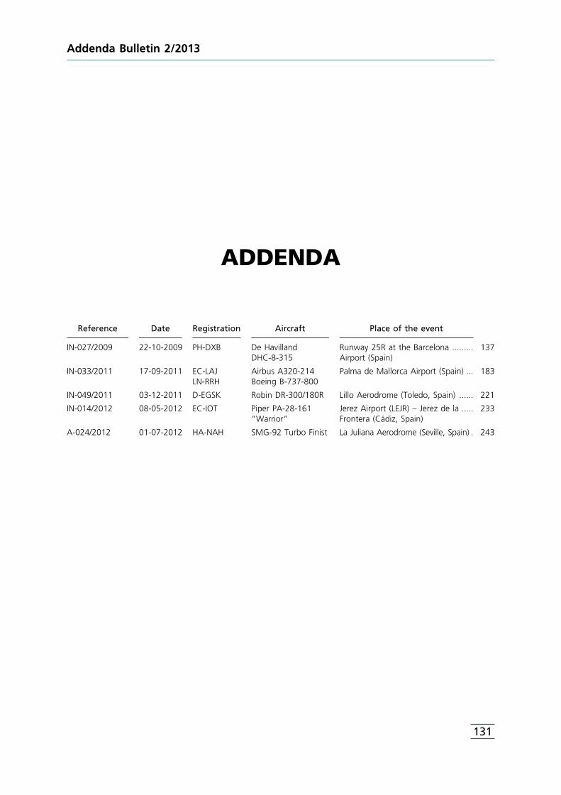
ADDENDA
Reference Date Registration Aircraft Place of the event
IN-027/2009 22-10-2009 PH-DXB De Havilland Runway 25R at the Barcelona ......... 137DHC-8-315 Airport (Spain)
IN-033/2011 17-09-2011 EC-LAJ Airbus A320-214 Palma de Mallorca Airport (Spain) ... 183LN-RRH Boeing B-737-800
IN-049/2011 03-12-2011 D-EGSK Robin DR-300/180R Lillo Aerodrome (Toledo, Spain) ...... 221
IN-014/2012 08-05-2012 EC-IOT Piper PA-28-161 Jerez Airport (LEJR) – Jerez de la ..... 233“Warrior” Frontera (Cádiz, Spain)
A-024/2012 01-07-2012 HA-NAH SMG-92 Turbo Finist La Juliana Aerodrome (Seville, Spain) . 243
131
Addenda Bulletin 2/2013

F o r e w o r d
This Bulletin is a technical document that reflects the point of view of theCivil Aviation Accident and Incident Investigation Commission (CIAIAC)regarding the circumstances of the accident object of the investigation, andits probable causes and consequences.
In accordance with the provisions in Article 5.4.1 of Annex 13 of theInternational Civil Aviation Convention; and with articles 5.5 of Regulation(UE) n° 996/2010, of the European Parliament and the Council, of 20October 2010; Article 15 of Law 21/2003 on Air Safety and articles 1, 4 and21.2 of Regulation 389/1998, this investigation is exclusively of a technicalnature, and its objective is the prevention of future civil aviation accidentsand incidents by issuing, if necessary, safety recommendations to preventfrom their reoccurrence. The investigation is not pointed to establish blameor liability whatsoever, and it’s not prejudging the possible decision taken bythe judicial authorities. Therefore, and according to above norms andregulations, the investigation was carried out using procedures notnecessarily subject to the guarantees and rights usually used for theevidences in a judicial process.
Consequently, any use of this Bulletin for purposes other than that ofpreventing future accidents may lead to erroneous conclusions orinterpretations.
This Bulletin was originally issued in Spanish. This English translation isprovided for information purposes only.
133
Addenda Bulletin 2/2013
A b b r e v i a t i o n s
00° Degrees00 °C Degrees centigradeAENA Aeropuertos Españoles y Navegación AéreaAFM Aircraft Flight ManualAGA Aerodromes, air routes and ground aidsAGL Above Ground LevelAIO Aeronautical Information OfficeAIM Aeronautical Information ManagementAIP Aeronautical Information PublicationAIS Airport Information ServiceAPU Auxiliary Power UnitARC Airworthiness Review CertificateARO Airport Reservations OfficeARP Aerodrome Reference PointATC Air Traffic ControlATIS Automated Terminal Information ServiceATPL(A) Air Transport Pilot License (Airplane)ATM Air Traffic ManagementC/B, CB Circuit BreakerCAT Instrument Landing Categorycc Cubic Centimeter(s)CIAIAC Comisión de Investigación de Accidentes e Incidentes de Aviación CivilCL Check ListCNS Communications, navigation and surveillanceCPHOW SAS flight dispatch/planningCPL(A) Commercial Pilot License (Airplane)CPT CaptainCRM Crew Resource ManagementCVR Cockpit Voice RecorderDEP DepartureDFDR Digital Flight Data RecorderECL Emergency Check ListEGPWS Enhanced Ground Proximity Warning SystemF/O First OfficerFA Flight attendantFDR Flight Data RecorderFH Flight HoursFIR Flight Information RegionFMS Flight Management Systemft Feetg Gravity accelerationGMC Ground Movement ControlGPWS Ground Proximity Warning Systemh Hour(s)HP Horse PowerhPa Hectopascal(s)IAS Indicated Air SpeedICAO International Civil Aviation OrganizationIFR Instrument Flight RulesILS Instrumental Landing SystemIR Instrument Flightkg Kilogram(s)KIAS Indicated Airspeed (knots)km Kilometer(s)km/h Kilometers/hourkt Knot(s)
Addenda Bulletin 2/2013
134
135
A b b r e v i a t i o n s
l Liter(s)LEBL Barcelona Airport ICAO codeLEJR Jerez Airport ICAO codeLEPA Palma de Mallorca Airport ICAO codeLESO San Sebastián Airport ICAO codem Meter(s)MAC Mean Aerodinamic ChordME Multi-engineMETAR Meteorological terminal Aviation Routine Weather ReportMHz Megahertz(s)MTOW Maximum Take Off WeightN NorthN2 Intermediate compressor speedNE North EastNM Nautical MilesNOF NOTAM Office InternationalNOTAM Notice to AirmanNW NorthwestOM Operations ManualP/N Part NumberPAPI Precision Approach Path IndicatorPAR Parachute drop ratingPF Pilot FlyingPIB Preflight Information BulletinPM Pilot MonitoringPNF Pilot Not FlyingPPL(A) Private Pilot Licence (Airplane)PTU Power Transfer UnitQNH Atmospheric Pressure (Q) at Nautical HeightQRH Quick Reference HandbookRNAV Area NavigationRPM Revolutions per minutes Second(s)S/N Serial NumberSAS Scandinavian AirlinesSET Single Engine Turbine licenseSHK Sweden Statens HaverikommissionSOP Standard Operating ProceduresSP Single PilotSSW South southwestTAS True AirspeedTWR Control TowerTWY TaxiWayUTC Universal Time CoordinatedVHF Very High FrequencyVle Maximum Velocity with Landing gear ExtendedVref Reference Landing SpeedW West
Addenda Bulletin 2/2013

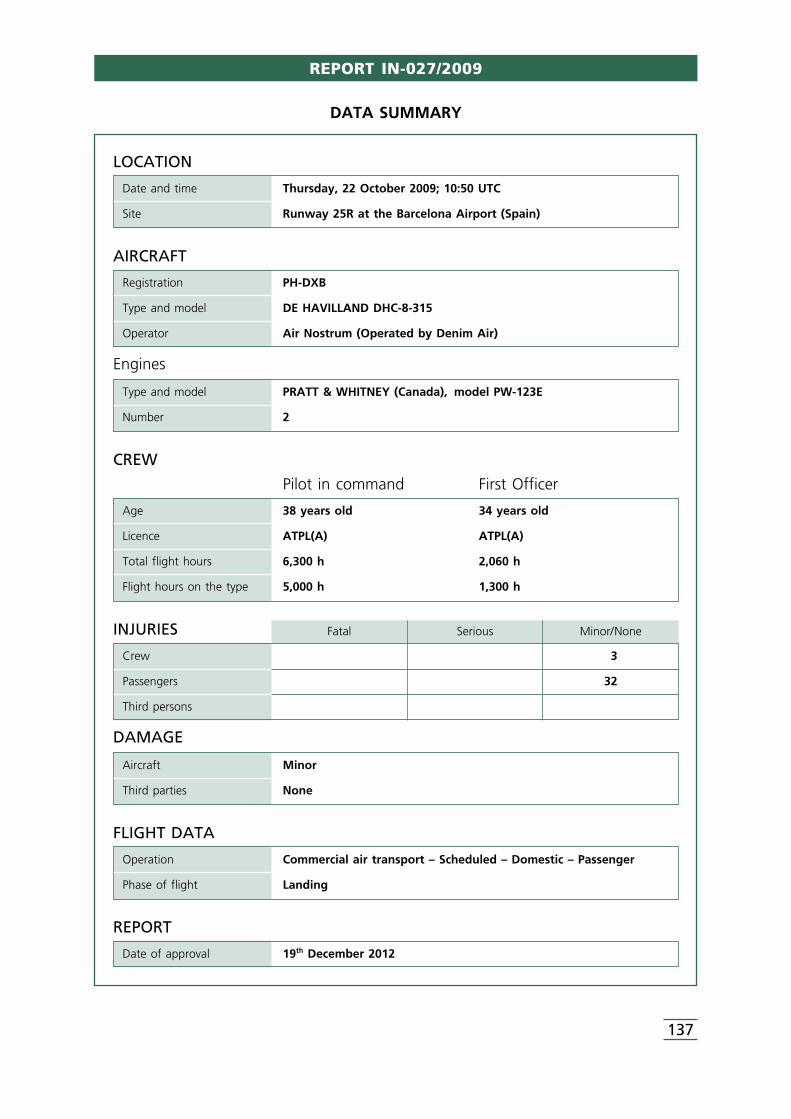
REPORT IN-027/2009
137
LOCATION
Date and time Thursday, 22 October 2009; 10:50 UTC
Site Runway 25R at the Barcelona Airport (Spain)
FLIGHT DATA
Operation Commercial air transport – Scheduled – Domestic – Passenger
Phase of flight Landing
REPORT
Date of approval 19th December 2012
CREW
Pilot in command First Officer
Age 38 years old 34 years old
Licence ATPL(A) ATPL(A)
Total flight hours 6,300 h 2,060 h
Flight hours on the type 5,000 h 1,300 h
AIRCRAFT
Registration PH-DXB
Type and model DE HAVILLAND DHC-8-315
Operator Air Nostrum (Operated by Denim Air)
Engines
Type and model PRATT & WHITNEY (Canada), model PW-123E
Number 2
INJURIES Fatal Serious Minor/None
Crew 3
Passengers 32
Third persons
DAMAGE
Aircraft Minor
Third parties None
DATA SUMMARY
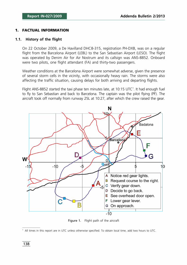
1 All times in this report are in UTC unless otherwise specified. To obtain local time, add two hours to UTC.
Report IN-027/2009
1. FACTUAL INFORMATION
1.1. History of the flight
On 22 October 2009, a De Havilland DHC8-315, registration PH-DXB, was on a regularflight from the Barcelona Airport (LEBL) to the San Sebastian Airport (LESO). The flightwas operated by Denim Air for Air Nostrum and its callsign was ANS-8852. Onboardwere two pilots, one flight attendant (FA) and thirty-two passengers.
Weather conditions at the Barcelona Airport were somewhat adverse, given the presenceof several storm cells in the vicinity, with occasionally heavy rain. The storms were alsoaffecting the traffic situation, causing delays for both arriving and departing flights.
Flight ANS-8852 started the taxi phase ten minutes late, at 10:15 UTC1. It had enough fuelto fly to San Sebastian and back to Barcelona. The captain was the pilot flying (PF). Theaircraft took off normally from runway 25L at 10:27, after which the crew raised the gear.
Figure 1. Flight path of the aircraft
138
Addenda Bulletin 2/2013
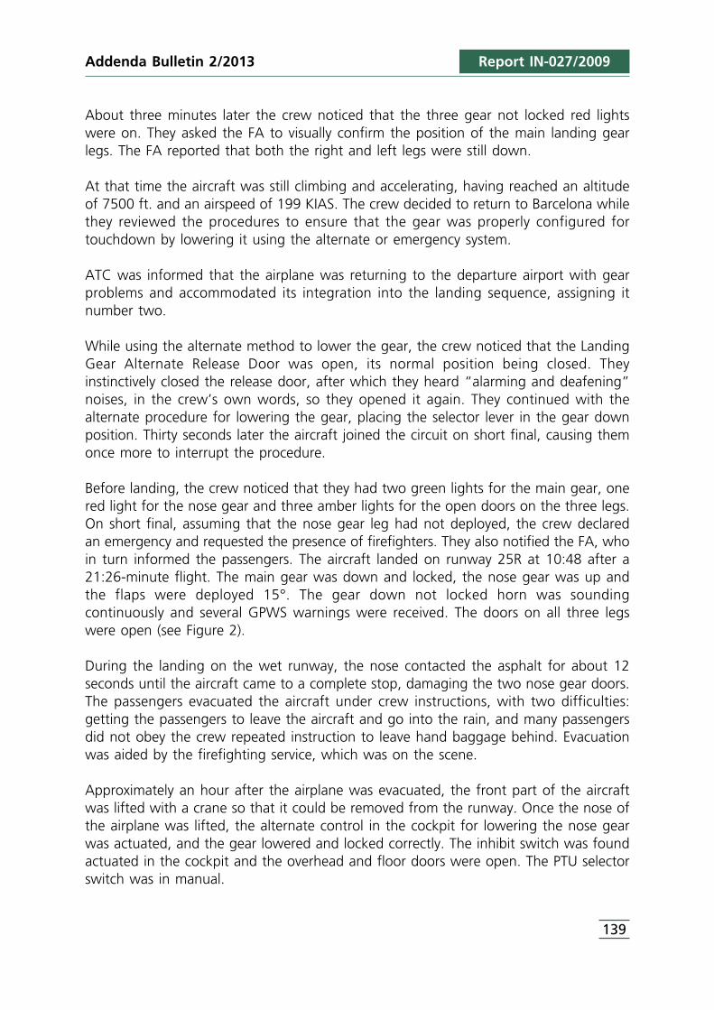
Addenda Bulletin 2/2013 Report IN-027/2009
About three minutes later the crew noticed that the three gear not locked red lightswere on. They asked the FA to visually confirm the position of the main landing gearlegs. The FA reported that both the right and left legs were still down.
At that time the aircraft was still climbing and accelerating, having reached an altitudeof 7500 ft. and an airspeed of 199 KIAS. The crew decided to return to Barcelona whilethey reviewed the procedures to ensure that the gear was properly configured fortouchdown by lowering it using the alternate or emergency system.
ATC was informed that the airplane was returning to the departure airport with gearproblems and accommodated its integration into the landing sequence, assigning itnumber two.
While using the alternate method to lower the gear, the crew noticed that the LandingGear Alternate Release Door was open, its normal position being closed. Theyinstinctively closed the release door, after which they heard “alarming and deafening”noises, in the crew’s own words, so they opened it again. They continued with thealternate procedure for lowering the gear, placing the selector lever in the gear downposition. Thirty seconds later the aircraft joined the circuit on short final, causing themonce more to interrupt the procedure.
Before landing, the crew noticed that they had two green lights for the main gear, onered light for the nose gear and three amber lights for the open doors on the three legs.On short final, assuming that the nose gear leg had not deployed, the crew declaredan emergency and requested the presence of firefighters. They also notified the FA, whoin turn informed the passengers. The aircraft landed on runway 25R at 10:48 after a21:26-minute flight. The main gear was down and locked, the nose gear was up andthe flaps were deployed 15°. The gear down not locked horn was soundingcontinuously and several GPWS warnings were received. The doors on all three legswere open (see Figure 2).
During the landing on the wet runway, the nose contacted the asphalt for about 12seconds until the aircraft came to a complete stop, damaging the two nose gear doors.The passengers evacuated the aircraft under crew instructions, with two difficulties:getting the passengers to leave the aircraft and go into the rain, and many passengersdid not obey the crew repeated instruction to leave hand baggage behind. Evacuationwas aided by the firefighting service, which was on the scene.
Approximately an hour after the airplane was evacuated, the front part of the aircraftwas lifted with a crane so that it could be removed from the runway. Once the nose ofthe airplane was lifted, the alternate control in the cockpit for lowering the nose gearwas actuated, and the gear lowered and locked correctly. The inhibit switch was foundactuated in the cockpit and the overhead and floor doors were open. The PTU selectorswitch was in manual.
139
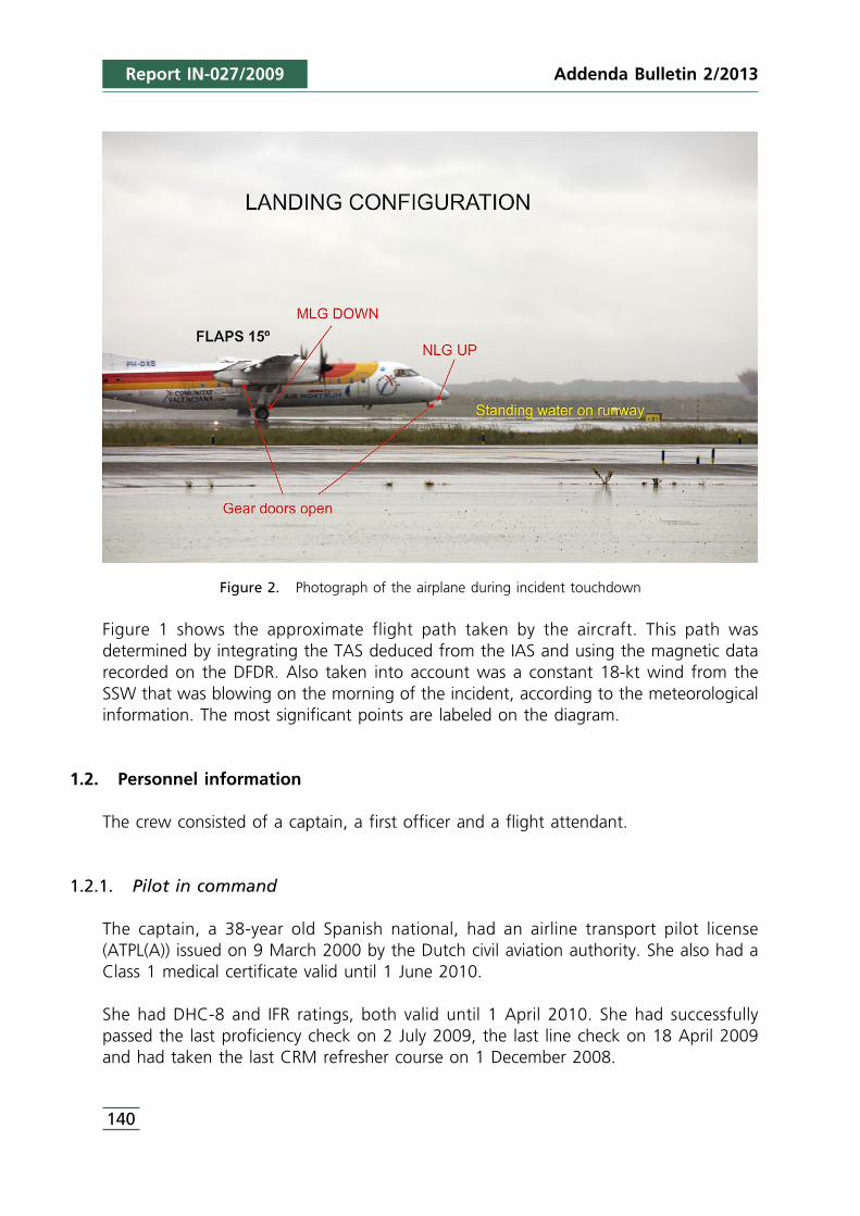
Report IN-027/2009
Figure 2. Photograph of the airplane during incident touchdown
Figure 1 shows the approximate flight path taken by the aircraft. This path wasdetermined by integrating the TAS deduced from the IAS and using the magnetic datarecorded on the DFDR. Also taken into account was a constant 18-kt wind from theSSW that was blowing on the morning of the incident, according to the meteorologicalinformation. The most significant points are labeled on the diagram.
1.2. Personnel information
The crew consisted of a captain, a first officer and a flight attendant.
1.2.1. Pilot in command
The captain, a 38-year old Spanish national, had an airline transport pilot license(ATPL(A)) issued on 9 March 2000 by the Dutch civil aviation authority. She also had aClass 1 medical certificate valid until 1 June 2010.
She had DHC-8 and IFR ratings, both valid until 1 April 2010. She had successfullypassed the last proficiency check on 2 July 2009, the last line check on 18 April 2009and had taken the last CRM refresher course on 1 December 2008.
140
Addenda Bulletin 2/2013
Addenda Bulletin 2/2013 Report IN-027/2009
The captain had a total of 6,300 flight hours, of which approximately 5,000 had beenon the DHC-8. She had flown 16:20 h in the last 30 days and 6 hours in the last 24hours. This was her first flight of the day, having gone on duty at 09:20, 45 minutesbefore the flight, which was scheduled for 10:05.
1.2.2. First officer
The first officer, a 34-year old Spanish national, had an airline transport pilot license(ATPL(A)) issued on 11 August 2009 by the Dutch civil aviation authority. He also hada Class 1 medical certificate valid until 7 March 2010.
He had DHC-8 and IFR ratings, valid since 1 August 2009, and had obtained a multi-engine aircraft rating on 7 June 2007. He had successfully passed the last proficiencycheck on 26 July 2009, the last line check on 15 May 2009 and had taken the last CRMrefresher course on 7 October 2009.
The first officer had a total of 2,060 flight hours, of which some 1,300 had been onthe DHC-8. He had flown 62:10 h in the last 30 days and 2:57 hours in the last 24hours, of which 1:33 had been on a flight from San Sebastian to Barcelona that samemorning and on the same aircraft. He had gone on duty at 04:45.
1.2.3. Flight attendant
There was a single crewmember in the passenger cabin, a licensed flight attendant (FA).She had gone on duty at 04:45 and had flown in on the San Sebastian-Barcelona flight.The stopover in Barcelona had lasted three hours.
1.3. Aircraft information
1.3.1. General
The De Havilland Canada DHC-8-315 DASH 8 is a high-wing aircraft designed for short-range regional air transportation. It was type certified in 1985. Nowadays the typecertificate holder is Bombardier Inc.
The incident aircraft, with Dutch registration PH-DXB, has serial number 589. Itsmaximum takeoff weight (MTOW) is 19,495 kg and it is configured to carry 50passengers. It has two Pratt & Whitney PW123E turboprop engines that generate2,380 HP.
141
Report IN-027/2009
1.3.2. Maintenance status
The incident aircraft had the relevant airworthiness review certificate, which expired on18 May 2010.
The maintenance data collected showed that the aircraft had accumulated 14,150 flighthours and 16,943 cycles.
All scheduled maintenance activities were up to date and its last overhaul had been inValencia in July 2007, with 9,572 h and 11,562 cycles on the aircraft. The lastmaintenance tasks consisted of changing the number 2 tire on the left main landinggear and the 75-hour inspection. There were two deferred items, the replacement ofthe FMS (Flight Management System) unit and of the #1 audio panel.
1.3.3. Weight and balance
The balance sheet that was prepared at the Barcelona Airport prior to dispatch recordedthe following weights:
• Total load: 2,798 kg• Dry operating weight: 12,592 kg• Actual zero fuel weight: 15,390 kg Maximum: 17,917 kg• Takeoff fuel: 2,450 kg• Actual takeoff weight: 17,840 kg Maximum: 19,495 kg• Trip fuel: 800 kg• Estimated landing weight: 17,040 kg Maximum: 19,051 kg
— Takeoff balance: 26.98 %MAC; min. 20%;,0 max. 40%— Landing balance: 26.61 %MAC; min. 19.5%; max 40%
The calculation assumed 13 passengers in rows 1 to 7 and 19 passengers in rows 8 to19, as per the load sheet.
Based on these load and balance conditions, it is estimated that moving half of thepassengers from the forward rows to the aft rows would shift the center of gravity aft by4% or 5% MAC. This shift could lower the load on the nose wheel by about 200 kg.
According to the operations manual, the approach speed with 15° flaps and these loadconditions (Vref) was 105 kt.
1.3.4. Information on the landing gear
This type of airplane has a retractable tricycle gear with two wheels on each leg. Themain legs, housed in the engine nacelles under the wings when retracted, deployforward, into the wind. The nose wheel deploys by rotating aft.
142
Addenda Bulletin 2/2013
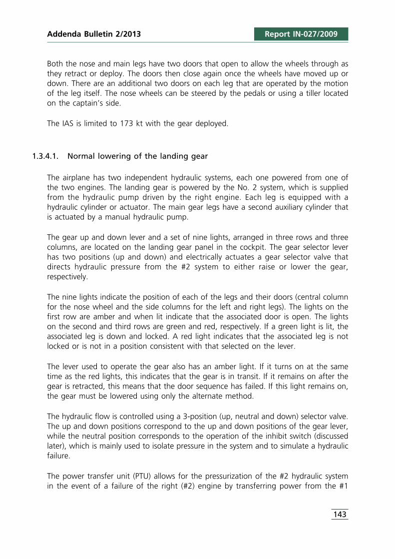
Addenda Bulletin 2/2013 Report IN-027/2009
Both the nose and main legs have two doors that open to allow the wheels through asthey retract or deploy. The doors then close again once the wheels have moved up ordown. There are an additional two doors on each leg that are operated by the motionof the leg itself. The nose wheels can be steered by the pedals or using a tiller locatedon the captain’s side.
The IAS is limited to 173 kt with the gear deployed.
1.3.4.1. Normal lowering of the landing gear
The airplane has two independent hydraulic systems, each one powered from one ofthe two engines. The landing gear is powered by the No. 2 system, which is suppliedfrom the hydraulic pump driven by the right engine. Each leg is equipped with ahydraulic cylinder or actuator. The main gear legs have a second auxiliary cylinder thatis actuated by a manual hydraulic pump.
The gear up and down lever and a set of nine lights, arranged in three rows and threecolumns, are located on the landing gear panel in the cockpit. The gear selector leverhas two positions (up and down) and electrically actuates a gear selector valve thatdirects hydraulic pressure from the #2 system to either raise or lower the gear,respectively.
The nine lights indicate the position of each of the legs and their doors (central columnfor the nose wheel and the side columns for the left and right legs). The lights on thefirst row are amber and when lit indicate that the associated door is open. The lightson the second and third rows are green and red, respectively. If a green light is lit, theassociated leg is down and locked. A red light indicates that the associated leg is notlocked or is not in a position consistent with that selected on the lever.
The lever used to operate the gear also has an amber light. If it turns on at the sametime as the red lights, this indicates that the gear is in transit. If it remains on after thegear is retracted, this means that the door sequence has failed. If this light remains on,the gear must be lowered using only the alternate method.
The hydraulic flow is controlled using a 3-position (up, neutral and down) selector valve.The up and down positions correspond to the up and down positions of the gear lever,while the neutral position corresponds to the operation of the inhibit switch (discussedlater), which is mainly used to isolate pressure in the system and to simulate a hydraulicfailure.
The power transfer unit (PTU) allows for the pressurization of the #2 hydraulic systemin the event of a failure of the right (#2) engine by transferring power from the #1
143
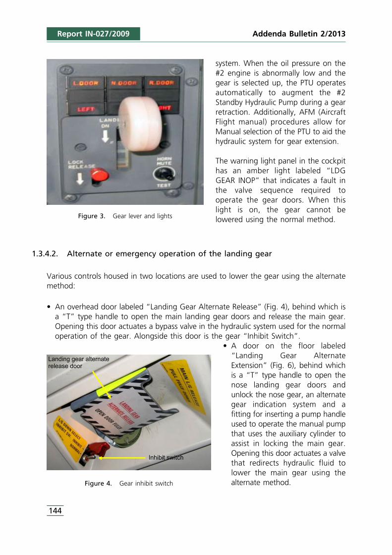
system. When the oil pressure on the#2 engine is abnormally low and thegear is selected up, the PTU operatesautomatically to augment the #2Standby Hydraulic Pump during a gearretraction. Additionally, AFM (AircraftFlight manual) procedures allow forManual selection of the PTU to aid thehydraulic system for gear extension.
The warning light panel in the cockpithas an amber light labeled “LDGGEAR INOP” that indicates a fault inthe valve sequence required tooperate the gear doors. When thislight is on, the gear cannot belowered using the normal method.
1.3.4.2. Alternate or emergency operation of the landing gear
Various controls housed in two locations are used to lower the gear using the alternatemethod:
• An overhead door labeled “Landing Gear Alternate Release” (Fig. 4), behind which isa “T” type handle to open the main landing gear doors and release the main gear.Opening this door actuates a bypass valve in the hydraulic system used for the normaloperation of the gear. Alongside this door is the gear “Inhibit Switch”.
• A door on the floor labeled“Landing Gear AlternateExtension” (Fig. 6), behind whichis a “T” type handle to open thenose landing gear doors andunlock the nose gear, an alternategear indication system and afitting for inserting a pump handleused to operate the manual pumpthat uses the auxiliary cylinder toassist in locking the main gear.Opening this door actuates a valvethat redirects hydraulic fluid tolower the main gear using thealternate method.
Figure 3. Gear lever and lights
Figure 4. Gear inhibit switch
Addenda Bulletin 2/2013
144
Report IN-027/2009
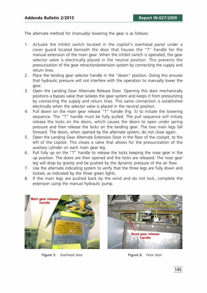
145
The alternate method for (manually) lowering the gear is as follows:
1. Actuate the inhibit switch located in the copilot’s overhead panel under a cover guard located beneath the door that houses the “T” handle for the manual extension of the main gear. When the inhibit switch is operated, the gearselector valve is electrically placed in the neutral position. This prevents thepressurization of the gear retraction/extension system by connecting the supply andreturn lines.
2. Place the landing gear selector handle in the “down” position. Doing this ensuresthat hydraulic pressure will not interfere with the operation to manually lower thegear.
3. Open the Landing Gear Alternate Release Door. Opening this door mechanicallypositions a bypass valve that isolates the gear system and keeps it from pressurizingby connecting the supply and return lines. This same connection is establishedelectrically when the selector valve is placed in the neutral position.
4. Pull down on the main gear release “T” handle (Fig. 5) to initiate the loweringsequence. The “T” handle must be fully pulled. The pull sequence will initialyrelease the locks on the doors, which causes the doors to open under springpressure and then release the locks on the landing gear. The two main legs fallforward. The doors, when opened by the alternate system, do not close again.
5. Open the Landing Gear Alternate Extension Door in the floor of the cockpit, to theleft of the copilot. This closes a valve that allows for the pressurization of theauxiliary cylinder on each main gear leg.
6. Pull fully up on the “T” handle to release the locks keeping the nose gear in theup position. The doors are then opened and the locks are released. The nose gearleg will drop by gravity and be pushed by the dynamic pressure of the air flow.
7. Use the alternate indicating system to verify that the three legs are fully down andlocked, as indicated by the three green lights.
8. If the main legs are pushed back by the wind and do not lock, complete theextension using the manual hydraulic pump.
Figure 5. Overhead door Figure 6. Floor door
Report IN-027/2009Addenda Bulletin 2/2013
Report IN-027/2009
1.4. Meteorological information
When the aircraft took off at 10:15, the weather was stormy with heavy rain at times.The wind direction was variable at 4 kt. The cloud ceiling was at 3.500 ft.
When the aircraft landed at 10:50, the weather was still stormy with intermittent rain.Horizontal visibility was between 7,000 and 6,000 m and the cloud ceiling had fallento 1,900 ft. The wind reported during the landing clearance was calm, though the11:00 METAR indicated the wind was at 8 kt.
The wind above Barcelona at flight level FL75 was from the south-southwest at between15 to 30 kt. The flight took place mainly below this level and encountered winds fromthe SSW at speeds of between 15 to 20 kt.
1.5. Communications
The aircraft was in contact with various approach control stations and with theBarcelona Airport tower. The transcript of these communications coincides with therecordings on the cockpit voice recorder (CVR). Radio communications were initially heldin English, though once the flight plan changed and the aircraft headed back toBarcelona, the crew changed to Spanish.
In Section 1.7.1, Cockpit Voice Recorder (CVR), the radio communications weresynchronized and sequenced with the cockpit communications so as to generate atimeline of the significant events that occurred during the flight.
1.6. Aerodrome information
The Barcelona-El Prat Airport is to the south of the city, near the sea, at an elevation of14 ft. It has three runways designated 25R-07L, 20-02 and 25L-07R. The first tworunways cross each other.
The runway where the incident flight landed, 25R, is 3,352 m long and 60 m wide. Theelevation of the threshold is 10 ft. It has a PAPI visual glide slope aid and a CAT II/III ILSinstrument aid. Both the visual and the ILS glide slopes have a 3° gradient.
1.7. Flight recorders
1.7.1. Cockpit Voice Recorder (CVR)
The aircraft had a solid-state cockpit voice recorder (CVR) with a maximum recordingtime of 120 minutes.
146
Addenda Bulletin 2/2013
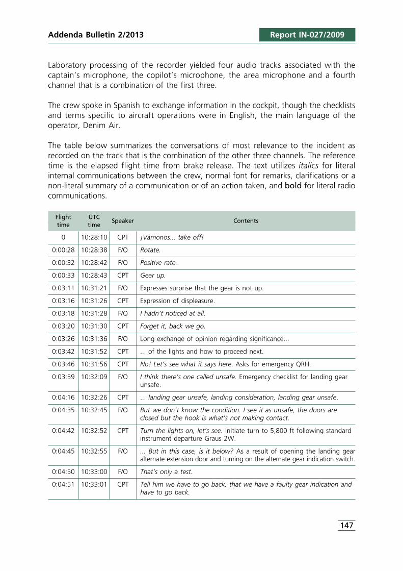
Addenda Bulletin 2/2013 Report IN-027/2009
Laboratory processing of the recorder yielded four audio tracks associated with thecaptain’s microphone, the copilot’s microphone, the area microphone and a fourthchannel that is a combination of the first three.
The crew spoke in Spanish to exchange information in the cockpit, though the checklistsand terms specific to aircraft operations were in English, the main language of theoperator, Denim Air.
The table below summarizes the conversations of most relevance to the incident asrecorded on the track that is the combination of the other three channels. The referencetime is the elapsed flight time from brake release. The text utilizes italics for literalinternal communications between the crew, normal font for remarks, clarifications or anon-literal summary of a communication or of an action taken, and bold for literal radiocommunications.
Flight UTCtime time
Speaker Contents
0 10:28:10 CPT ¡Vámonos... take off!
0:00:28 10:28:38 F/O Rotate.
0:00:32 10:28:42 F/O Positive rate.
0:00:33 10:28:43 CPT Gear up.
0:03:11 10:31:21 F/O Expresses surprise that the gear is not up.
0:03:16 10:31:26 CPT Expression of displeasure.
0:03:18 10:31:28 F/O I hadn’t noticed at all.
0:03:20 10:31:30 CPT Forget it, back we go.
0:03:26 10:31:36 F/O Long exchange of opinion regarding significance...
0:03:42 10:31:52 CPT ... of the lights and how to proceed next.
0:03:46 10:31:56 CPT No! Let’s see what it says here. Asks for emergency QRH.
0:03:59 10:32:09 F/O I think there’s one called unsafe. Emergency checklist for landing gearunsafe.
0:04:16 10:32:26 CPT ... landing gear unsafe, landing consideration, landing gear unsafe.
0:04:35 10:32:45 F/O But we don’t know the condition. I see it as unsafe, the doors areclosed but the hook is what’s not making contact.
0:04:42 10:32:52 CPT Turn the lights on, let’s see. Initiate turn to 5,800 ft following standardinstrument departure Graus 2W.
0:04:45 10:32:55 F/O ... But in this case, is it below? As a result of opening the landing gearalternate extension door and turning on the alternate gear indication switch.
0:04:50 10:33:00 F/O That’s only a test.
0:04:51 10:33:01 CPT Tell him we have to go back, that we have a faulty gear indication andhave to go back.
147
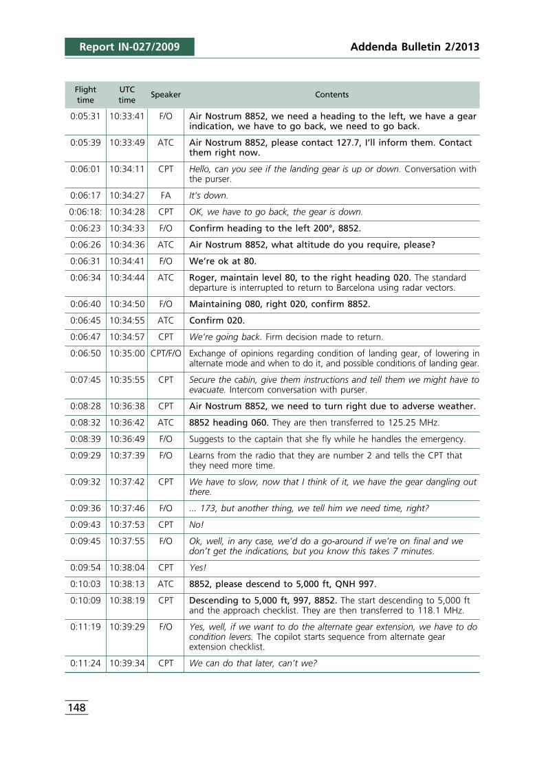
Report IN-027/2009
Flight UTCtime time
Speaker Contents
0:05:31 10:33:41 F/O Air Nostrum 8852, we need a heading to the left, we have a gearindication, we have to go back, we need to go back.
0:05:39 10:33:49 ATC Air Nostrum 8852, please contact 127.7, I’ll inform them. Contactthem right now.
0:06:01 10:34:11 CPT Hello, can you see if the landing gear is up or down. Conversation withthe purser.
0:06:17 10:34:27 FA It’s down.
0:06:18: 10:34:28 CPT OK, we have to go back, the gear is down.
0:06:23 10:34:33 F/O Confirm heading to the left 200°, 8852.
0:06:26 10:34:36 ATC Air Nostrum 8852, what altitude do you require, please?
0:06:31 10:34:41 F/O We’re ok at 80.
0:06:34 10:34:44 ATC Roger, maintain level 80, to the right heading 020. The standarddeparture is interrupted to return to Barcelona using radar vectors.
0:06:40 10:34:50 F/O Maintaining 080, right 020, confirm 8852.
0:06:45 10:34:55 ATC Confirm 020.
0:06:47 10:34:57 CPT We’re going back. Firm decision made to return.
0:06:50 10:35:00 CPT/F/O Exchange of opinions regarding condition of landing gear, of lowering inalternate mode and when to do it, and possible conditions of landing gear.
0:07:45 10:35:55 CPT Secure the cabin, give them instructions and tell them we might have toevacuate. Intercom conversation with purser.
0:08:28 10:36:38 CPT Air Nostrum 8852, we need to turn right due to adverse weather.
0:08:32 10:36:42 ATC 8852 heading 060. They are then transferred to 125.25 MHz.
0:08:39 10:36:49 F/O Suggests to the captain that she fly while he handles the emergency.
0:09:29 10:37:39 F/O Learns from the radio that they are number 2 and tells the CPT thatthey need more time.
0:09:32 10:37:42 CPT We have to slow, now that I think of it, we have the gear dangling outthere.
0:09:36 10:37:46 F/O ... 173, but another thing, we tell him we need time, right?
0:09:43 10:37:53 CPT No!
0:09:45 10:37:55 F/O Ok, well, in any case, we’d do a go-around if we’re on final and wedon’t get the indications, but you know this takes 7 minutes.
0:09:54 10:38:04 CPT Yes!
0:10:03 10:38:13 ATC 8852, please descend to 5,000 ft, QNH 997.
0:10:09 10:38:19 CPT Descending to 5,000 ft, 997, 8852. The start descending to 5,000 ftand the approach checklist. They are then transferred to 118.1 MHz.
0:11:19 10:39:29 F/O Yes, well, if we want to do the alternate gear extension, we have to docondition levers. The copilot starts sequence from alternate gearextension checklist.
0:11:24 10:39:34 CPT We can do that later, can’t we?
148
Addenda Bulletin 2/2013
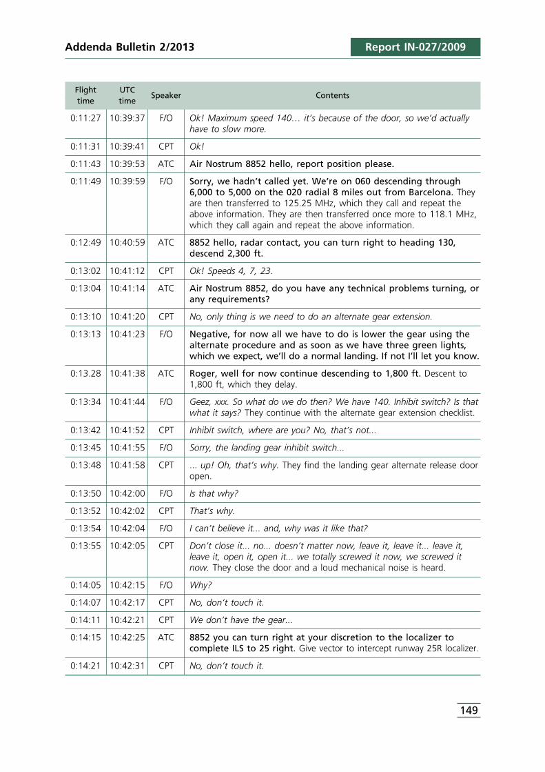
Addenda Bulletin 2/2013 Report IN-027/2009
Flight UTCtime time
Speaker Contents
0:11:27 10:39:37 F/O Ok! Maximum speed 140… it’s because of the door, so we’d actuallyhave to slow more.
0:11:31 10:39:41 CPT Ok!
0:11:43 10:39:53 ATC Air Nostrum 8852 hello, report position please.
0:11:49 10:39:59 F/O Sorry, we hadn’t called yet. We’re on 060 descending through6,000 to 5,000 on the 020 radial 8 miles out from Barcelona. Theyare then transferred to 125.25 MHz, which they call and repeat theabove information. They are then transferred once more to 118.1 MHz,which they call again and repeat the above information.
0:12:49 10:40:59 ATC 8852 hello, radar contact, you can turn right to heading 130,descend 2,300 ft.
0:13:02 10:41:12 CPT Ok! Speeds 4, 7, 23.
0:13:04 10:41:14 ATC Air Nostrum 8852, do you have any technical problems turning, orany requirements?
0:13:10 10:41:20 CPT No, only thing is we need to do an alternate gear extension.
0:13:13 10:41:23 F/O Negative, for now all we have to do is lower the gear using thealternate procedure and as soon as we have three green lights,which we expect, we’ll do a normal landing. If not I’ll let you know.
0:13.28 10:41:38 ATC Roger, well for now continue descending to 1,800 ft. Descent to1,800 ft, which they delay.
0:13:34 10:41:44 F/O Geez, xxx. So what do we do then? We have 140. Inhibit switch? Is thatwhat it says? They continue with the alternate gear extension checklist.
0:13:42 10:41:52 CPT Inhibit switch, where are you? No, that’s not...
0:13:45 10:41:55 F/O Sorry, the landing gear inhibit switch...
0:13:48 10:41:58 CPT ... up! Oh, that’s why. They find the landing gear alternate release dooropen.
0:13:50 10:42:00 F/O Is that why?
0:13:52 10:42:02 CPT That’s why.
0:13:54 10:42:04 F/O I can’t believe it... and, why was it like that?
0:13:55 10:42:05 CPT Don’t close it... no... doesn’t matter now, leave it, leave it... leave it,leave it, open it, open it... we totally screwed it now, we screwed itnow. They close the door and a loud mechanical noise is heard.
0:14:05 10:42:15 F/O Why?
0:14:07 10:42:17 CPT No, don’t touch it.
0:14:11 10:42:21 CPT We don’t have the gear...
0:14:15 10:42:25 ATC 8852 you can turn right at your discretion to the localizer tocomplete ILS to 25 right. Give vector to intercept runway 25R localizer.
0:14:21 10:42:31 CPT No, don’t touch it.
149
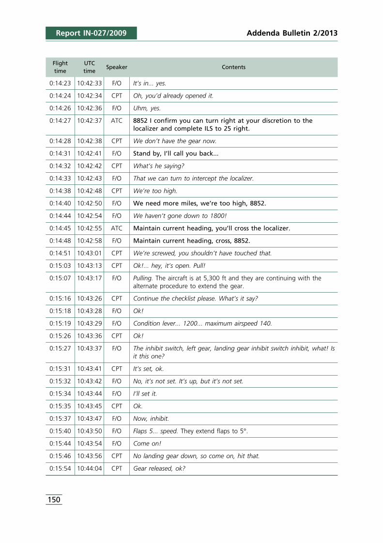
Report IN-027/2009
Flight UTCtime time
Speaker Contents
0:14:23 10:42:33 F/O It’s in... yes.
0:14:24 10:42:34 CPT Oh, you’d already opened it.
0:14:26 10:42:36 F/O Uhm, yes.
0:14:27 10:42:37 ATC 8852 I confirm you can turn right at your discretion to thelocalizer and complete ILS to 25 right.
0:14:28 10:42:38 CPT We don’t have the gear now.
0:14:31 10:42:41 F/O Stand by, I’ll call you back...
0:14:32 10:42:42 CPT What’s he saying?
0:14:33 10:42:43 F/O That we can turn to intercept the localizer.
0:14:38 10:42:48 CPT We’re too high.
0:14:40 10:42:50 F/O We need more miles, we’re too high, 8852.
0:14:44 10:42:54 F/O We haven’t gone down to 1800!
0:14:45 10:42:55 ATC Maintain current heading, you’ll cross the localizer.
0:14:48 10:42:58 F/O Maintain current heading, cross, 8852.
0:14:51 10:43:01 CPT We’re screwed, you shouldn’t have touched that.
0:15:03 10:43:13 CPT Ok!... hey, it’s open. Pull!
0:15:07 10:43:17 F/O Pulling. The aircraft is at 5,300 ft and they are continuing with thealternate procedure to extend the gear.
0:15:16 10:43:26 CPT Continue the checklist please. What’s it say?
0:15:18 10:43:28 F/O Ok!
0:15:19 10:43:29 F/O Condition lever... 1200... maximum airspeed 140.
0:15:26 10:43:36 CPT Ok!
0:15:27 10:43:37 F/O The inhibit switch, left gear, landing gear inhibit switch inhibit, what! Isit this one?
0:15:31 10:43:41 CPT It’s set, ok.
0:15:32 10:43:42 F/O No, it’s not set. It’s up, but it’s not set.
0:15:34 10:43:44 F/O I’ll set it.
0:15:35 10:43:45 CPT Ok.
0:15:37 10:43:47 F/O Now, inhibit.
0:15:40 10:43:50 F/O Flaps 5... speed. They extend flaps to 5°.
0:15:44 10:43:54 F/O Come on!
0:15:46 10:43:56 CPT No landing gear down, so come on, hit that.
0:15:54 10:44:04 CPT Gear released, ok?
150
Addenda Bulletin 2/2013
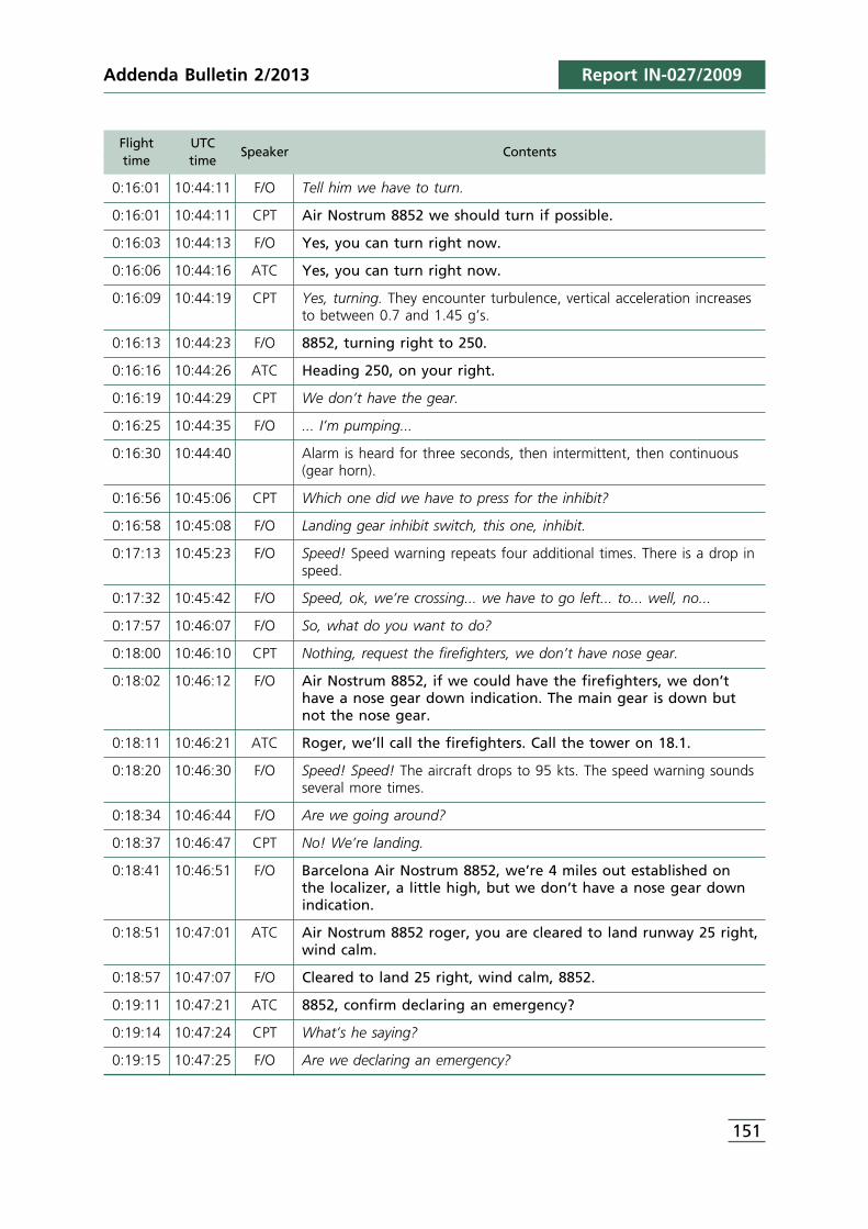
Addenda Bulletin 2/2013 Report IN-027/2009
Flight UTCtime time
Speaker Contents
0:16:01 10:44:11 F/O Tell him we have to turn.
0:16:01 10:44:11 CPT Air Nostrum 8852 we should turn if possible.
0:16:03 10:44:13 F/O Yes, you can turn right now.
0:16:06 10:44:16 ATC Yes, you can turn right now.
0:16:09 10:44:19 CPT Yes, turning. They encounter turbulence, vertical acceleration increasesto between 0.7 and 1.45 g’s.
0:16:13 10:44:23 F/O 8852, turning right to 250.
0:16:16 10:44:26 ATC Heading 250, on your right.
0:16:19 10:44:29 CPT We don’t have the gear.
0:16:25 10:44:35 F/O ... I’m pumping...
0:16:30 10:44:40 Alarm is heard for three seconds, then intermittent, then continuous(gear horn).
0:16:56 10:45:06 CPT Which one did we have to press for the inhibit?
0:16:58 10:45:08 F/O Landing gear inhibit switch, this one, inhibit.
0:17:13 10:45:23 F/O Speed! Speed warning repeats four additional times. There is a drop inspeed.
0:17:32 10:45:42 F/O Speed, ok, we’re crossing... we have to go left... to... well, no...
0:17:57 10:46:07 F/O So, what do you want to do?
0:18:00 10:46:10 CPT Nothing, request the firefighters, we don’t have nose gear.
0:18:02 10:46:12 F/O Air Nostrum 8852, if we could have the firefighters, we don’thave a nose gear down indication. The main gear is down but not the nose gear.
0:18:11 10:46:21 ATC Roger, we’ll call the firefighters. Call the tower on 18.1.
0:18:20 10:46:30 F/O Speed! Speed! The aircraft drops to 95 kts. The speed warning soundsseveral more times.
0:18:34 10:46:44 F/O Are we going around?
0:18:37 10:46:47 CPT No! We’re landing.
0:18:41 10:46:51 F/O Barcelona Air Nostrum 8852, we’re 4 miles out established on the localizer, a little high, but we don’t have a nose gear downindication.
0:18:51 10:47:01 ATC Air Nostrum 8852 roger, you are cleared to land runway 25 right,wind calm.
0:18:57 10:47:07 F/O Cleared to land 25 right, wind calm, 8852.
0:19:11 10:47:21 ATC 8852, confirm declaring an emergency?
0:19:14 10:47:24 CPT What’s he saying?
0:19:15 10:47:25 F/O Are we declaring an emergency?
151
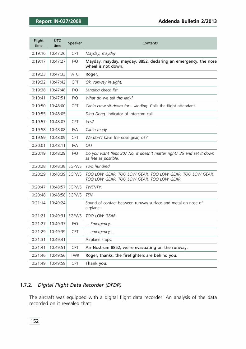
Report IN-027/2009
Flight UTCtime time
Speaker Contents
0:19:16 10:47:26 CPT Mayday, mayday.
0:19:17 10:47:27 F/O Mayday, mayday, mayday, 8852, declaring an emergency, the nosewheel is not down.
0:19:23 10:47:33 ATC Roger.
0:19:32 10:47:42 CPT Ok, runway in sight.
0:19:38 10:47:48 F/O Landing check list.
0:19:41 10:47:51 F/O What do we tell this lady?
0:19:50 10:48:00 CPT Cabin crew sit down for... landing. Calls the flight attendant.
0:19:55 10:48:05 Ding Dong. Indicator of intercom call.
0:19:57 10:48:07 CPT Yes?
0:19:58 10:48:08 F/A Cabin ready.
0:19:59 10:48:09 CPT We don’t have the nose gear, ok?
0:20:01 10:48:11 F/A Ok!
0:20:19 10:48:29 F/O Do you want flaps 30? No, it doesn’t matter right? 25 and set it downas late as possible.
0:20:28 10:48:38 EGPWS Two hundred
0:20:29 10:48:39 EGPWS TOO LOW GEAR, TOO LOW GEAR, TOO LOW GEAR, TOO LOW GEAR,TOO LOW GEAR, TOO LOW GEAR, TOO LOW GEAR.
0:20:47 10:48:57 EGPWS TWENTY.
0:20:48 10:48:58 EGPWS TEN.
0:21:14 10:49:24 Sound of contact between runway surface and metal on nose ofairplane.
0:21:21 10:49:31 EGPWS TOO LOW GEAR.
0:21:27 10:49:37 F/O ... Emergency.
0:21:29 10:49:39 CPT ... emergency,...
0:21:31 10:49:41 Airplane stops.
0:21:41 10:49:51 CPT Air Nostrum 8852, we’re evacuating on the runway.
0:21:46 10:49:56 TWR Roger, thanks, the firefighters are behind you.
0:21:49 10:49:59 CPT Thank you.
1.7.2. Digital Flight Data Recorder (DFDR)
The aircraft was equipped with a digital flight data recorder. An analysis of the datarecorded on it revealed that:
152
Addenda Bulletin 2/2013
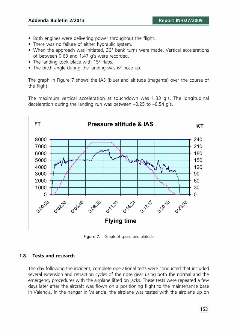
Addenda Bulletin 2/2013 Report IN-027/2009
• Both engines were delivering power throughout the flight.• There was no failure of either hydraulic system.• When the approach was initiated, 30° bank turns were made. Vertical accelerations
of between 0.63 and 1.47 g’s were recorded.• The landing took place with 15° flaps.• The pitch angle during the landing was 6° nose up.
The graph in Figure 7 shows the IAS (blue) and altitude (magenta) over the course ofthe flight.
The maximum vertical acceleration at touchdown was 1.33 g’s. The longitudinaldeceleration during the landing run was between –0.25 to –0.54 g’s.
Figure 7. Graph of speed and altitude
1.8. Tests and research
The day following the incident, complete operational tests were conducted that includedseveral extension and retraction cycles of the nose gear using both the normal and theemergency procedures with the airplane lifted on jacks. These tests were repeated a fewdays later after the aircraft was flown on a positioning flight to the maintenance basein Valencia. In the hangar in Valencia, the airplane was tested with the airplane up on
153
Report IN-027/2009
jacks, energized with electrical and hydraulic power from ground equipment and withthe damaged doors on the nose gear removed.
The results were as follows:
1. The extension and retraction cycles of the nose and main gear were satisfactory.2. The extensions using the alternate procedure were completed normally when the
mechanical proportional valve for the nose gear doors was placed in its properposition. When this valve was not in its proper position, very long gear extensiontimes of up to 225 seconds were recorded.
3. Repeating the gear retraction using the normal method, that is, raising the gearselector lever but leaving the overhead door open and the floor door closed,failed to raise the gear and left the three red gear unsafe lights energized.
4. With conditions as in point 3 above, closing the overhead door started the processof retracting the landing gear legs, with the door lights turning on momentarilybefore turning off when the legs were locked in the up position.
5. Repeating the retraction using the normal system, that is, raising the gear selectorlever and leaving both the overhead door and the floor door open, failed toraise the gear and left the three red gear unsafe lights energized.
6. With conditions as in point 5 above, closing the overhead door started the processof retracting the nose gear lever with the main legs remaining extended. When thenose gear retracted and locked in the up position, its indicating light turned off.The red lights for the main gear legs remained on. On the alternate indicatingsystem there were two green lights corresponding to the main gear legs down andlocked.
7. In cases 4 and 6, the PTU motor pump turned on.
1.9. Organizational and management information
1.9.1. Procedures involving the extension of the landing gear
Denim Air had manuals with flight procedures in them containing normal andemergency checklists for use by its crews.
The preface to the emergency checklists contains guidelines to be followed when doingsaid lists:
• Crews must execute the procedures correctly, using the ECL (Emergency Checklist),the combined skills of both pilots and, most of all, sound judgment.
• The ECLs are to be read out loud by the PNF (unless otherwise specified) so that thePF can remain informed of the progress of the procedure.
• All actions, selections and switch manipulations that are not reversible shall beconfirmed by both pilots prior to execution.
154
Addenda Bulletin 2/2013
Addenda Bulletin 2/2013 Report IN-027/2009
• When an emergency situation occurs, the nature of the fault must be clearlyestablished by one pilot and confirmed by the other.
• The PF initiates the applicable procedure with the term “ACTION”.• Each ECL procedure shall be started with the PNF stating the name of the checklist
in the applicable procedure.• When the specific checklist is completed, the PNF must announce “CHECKLIST
COMPLETE”.
Part B of the Denim Air Operations Manual, Emergency Procedures, “PilotIncapacitation”, states that whenever the PM notifies the PF of a deviation from thedesired flight profile, the PF shall reply “Checked correcting”. If the PF does not reply,the PM will notify him one more time and if there is again no reply, the PM shall assumethat the PF is incapacitated and take the controls of the airplane stating “My control”.
1.9.1.1. Pre-flight
Line 4 of the normal PRE-FLIGHT checklist calls for a check of the position of thealternate landing gear controls:
Alternate landing gear controls .................................................... CHECKED
1.9.1.2. Failure of the #2 hydraulic system. ECL 18
In the event of a declared failure of the #2 hydraulic system, which supplies the normalsystem for extending and retracting the landing gear, the procedure first has the pilotcheck if the hydraulic fluid level is normal.
Pressure is then reestablished using the stand-by hydraulic pump and the PTU. Ifunsuccessful, the procedure refers to the one for the alternate gear extension.
A warning states that the procedure must be completed before the start of theapproach, that the procedure could take up to seven minutes and that the nosewheelsteering and parking brakes, among others, will be lost.
Some landing considerations are presented and a statement warns against using thePTU in manual during the approach.
1.9.1.3. Defective operation of the landing gear indicators. ECL 24A
If the landing gear indicating lights are suspected of working abnormally, the gear downand locked position is to be checked using the indicators installed beneath the floor
155
Report IN-027/2009
door. The procedure ends with the closing of the floor door before proceeding with anormal landing or with the alternate extension of the gear.
1.9.1.4. Gear light LDG INOP CAUTION LIGHT. ECL 24B
The procedure states that if this light is activated, the gear must be lowered using thealternate procedure and to land as soon as possible.
1.9.1.5. Alternate landing gear extension. ECL 25
The preliminary notes warn that the procedure can take up to seven minutes to executeand that it must be completed prior to the final approach. The PTU must not be selectedto manual during the approach.
The procedure notes that releasing the locks on the retracted gear may require pullingon the handle with a force greater than that experienced during practice extensions.
The full procedure is included in Appendix A2. It starts with opening the overhead doorand releasing the main gear and then checking the door and left and right leg gearindicators. The nose gear is then released, followed by a check of its doors and locks.Both the overhead and the floor doors must be left open.
1.9.1.6. Landing gear unsafe. ECL 26
If a landing is performed with the nose gear up and both main gear legs extended, itstates to have the passengers’ seats in the aft seats, to lower the nose before the effectof the elevator is lost and not to exceed a 5° up angle on the flare.
In preparation for the landing, the crew is instructed to open the E5 C/B (gear warning)and the B3/B9 C/B on the EGPWS and to warn of a possible evacuation. The entireprocedure is included in Appendix A1.
1.10. Additional information
1.10.1. Emergency checklists associated with the landing gear used by otheroperators and the manufacturer
In page 11-2 of the QRH of Air Nostrum, operator of the flight and also an operator ofthe same DHC8-315 aircraft, there is a “Landing Gear Unsafe” procedure that refers tothe condition of the active landing gear unsafe lights. It is attached as Appendix B1.
156
Addenda Bulletin 2/2013
Addenda Bulletin 2/2013 Report IN-027/2009
In this case, once the speed limitation is established, the list requires checking that theoverhead door is closed and that the inhibit switch is in its normal position. If underthese conditions the gear unsafe lights go out, the procedure allows for the normalcontinuation of the flight.
Checklists used by the operator Deim Air, normal and emergency checklists related withthis event, and mentioned on precedent point 1.9.-Organizational and managementinformation, were coherent with normal and emergency checklists approved andrecommended by the manufacturer, according to data compiled and submitted bythem.
2. ANALYSIS
2.1. Sequence of actions involving the landing gear system
It was the first flight of the day for the captain, but not for the rest of the crew, whichhad already flown the reverse of the route planned for this flight. On this leg the captain(CPT) was the pilot flying (PF) and the copilot (FO) was the pilot monitoring (PM). TheFO conducted the walk-around check while the CPT did the pre-flight procedures in thecockpit (pre-flight checklists).
The “Landing Gear Alternate Release Door”, located in the overhead in the cockpit, wasprobably partially open when the crew reported to the airplane, but if so, this was notdetected either by the CPT during her check of the cockpit or subsequently by eitherpilot at any time prior to takeoff. The airplane thus took off with this conditionuncorrected.
Under these circumstances, the bypass valve prevents the pressurization of the landinggear, meaning that it does not retract when the gear selector lever is placed in the upposition.
When the gear lever was actuated after takeoff, the crew, which was probablyfocused on flying the airplane along the assigned instrument departure in difficultweather conditions with abundant clouds and storms nearby, did not detect anythingabnormal.
Some three minutes after takeoff the crew saw the three red lights indicating a gearunsafe situation. The crew was unable to identify the condition of the gear, discussingit for several minutes along with which emergency checklist to use.
The CPT decided they had to return to Barcelona and informed ATC, which startedsupplying them with radar vectors to runway 25R along a wide circuit to the right, tothe northwest of the airport.
157
Report IN-027/2009
They asked the flight attendant (FA) to visually verify that the main gear was down. Theyalso opened the “Landing Gear Alternate Extension Door” and verified that the threegreen lights turned on when the associated switch was activated, but based on theirown statements they could not determine whether the green lights indicated that thegear was down and locked or if it was only a test indication. The door was not closedafter said lights were checked, as indicated in the corresponding procedure (ECL 24A).The bypass valve on the main gear alternate hydraulic system thus remained activated.
They finally concluded that all of the legs must be down and locked, but nonethelessdecided to extend the gear using the alternate system.
On a parallel course to the runway, some 5 NM to the NW, it was probably then thatthey actuated the manual selection switch on the PTU, though they would not havenoticed any consequences. Since the #2 hydraulic system was pressurized and therewere no hydraulic loads, the pressures at either end of the PTU motor pump werebalanced and thus the PTU would not have rotated.
The crew stayed on a NE heading on a long downwind leg while they combatted theemergency and decided to execute the alternate landing gear extension procedure. Nearthe base leg of the circuit (point E in Fig. 1), they started the alternate extensionprocedure by looking for the inhibit switch. It was then that they discovered theoverhead door open.
After this, the flight crew temporarily closed the overhead door, which initiated aretraction of the entire landing gear apparently. The PTU, now loaded by the cylinders,started to rotate, making an “alarming and deafening” noise, according to the crew.Since the #2 engine was still rotating normally and supplying oil pressure, the only wayto operate the PTU was to place it in manual. The nose gear doors would have openedto let the wheels through, turning on the corresponding amber light, and the nose legwould have fully retracted until it locked, turning off its amber indicating light.
The noise from the PTU made the crew open the overhead door again, whichreactivated the bypass of the hydraulic system. The floor door very likely remained openand thus the bypass of the alternate, or standby, hydraulic system remained closed.Under these conditions, the auxiliary cylinder cannot move, and thus cannot provide ahydraulic lock for the main legs regardless of their position. The main legs, therefore,did not move from the down position, nor would they unlock from said position.
Had the crew not left the floor door open and had they not selected the PTU to manual,the landing gear would have fully retracted without making any abnormal noises. All ofthe gear lights would have gone out and they could have continued the flight.
Interrupting the alternate gear extension procedure for the reasons stated above, thecrew resumed it later by selecting the gear down procedure and pulling on the lever to
158
Addenda Bulletin 2/2013
Addenda Bulletin 2/2013 Report IN-027/2009
release the main gear. As already indicated, the main legs were already down but therelease of the locks resulted in the main gear doors opening. The photo in Figure 2shows that the aircraft in fact had its main gear doors open. The CPT then noticedbased on the cockpit indications that the nose gear was not extended and ordered theFO to pull on the corresponding handle.
Fig. 2 shows that the nose gear doors were open, which confirms that the copilot pulledon their release handle. As the procedure warns, the force applied may not have beensufficient, meaning that the gear would have remained locked in the up position. Thealternate gear position system would have shown two green lights for the main geardown and locked and the light associated with the nose gear off, which informed thecrew that they would have to land without the nose gear.
Later, when the aircraft was removed from the runway, the handle was pulled again,unlocking the nose gear, which extended without any problems.
Even though the main gear was correctly extended, the copilot actuated the stand-byhand pump, which is only necessary to fully extend the main gear if it is partiallyextended.
At that time the aircraft was on final approach and had joined the airport’s trafficpattern. The crew was preparing for the imminent landing but without having preparedthe aircraft in accordance with the emergency landing procedure with the nose gear up.The turns were performed at a bank angle of under 30° but the acceleration wasbetween 0.63 and 1.47 g’s, indicative of turbulence.
The main gear touched down a little after twenty minutes after the takeoff with avertical acceleration of 1.33 g’s. The airplane came to a full stop 43 s after touchdown.The nose was in contact with the ground for the last 12 of those seconds.
The water on the runway helped reduce the friction between the nose and the asphaltand eliminated any chance of sparking.
2.2. The overhead door in the procedures of manufacturer and Denim Air
None of manufacturer De Havilland and Denim Air’s procedures considered that theposition of the overhead “Landing Gear Alternate Release Door” could be the causeof the inability to retract the gear. In the event of an unsafe gear indication, the crewwas instructed to perform other emergency procedures, including the alternateextension of the landing gear. Had a procedure been available to the crew thatincluded a check of the position of this door, the crew could have quickly ascertainedits abnormal position, corrected it and retracted the gear, allowing them to continuewith the flight normally.
159

Report IN-027/2009
Such a procedure containing this check called Landing gear unsafe, and enclosed likeappendix B1, has been identified in an operator with wide experience with this aircrafttype. It thus seems reasonable to recommend to the manufacturer De Haviland-Bombardier and to Denim Air that they develop a similar procedure.
2.3. Execution of the procedures by the crew
The CVR recordings raise justified doubts regarding the way in which the procedureswere followed. There were no clear oral references to the procedures in use at any giventime, to each pilot’s assessment of the situation, to the actions they were taking or tothe completion of the procedures.
The procedures were constantly interrupted by operational considerations, by ATCcommunications and by the attention required by the weather situation. The crew’sattention also drifted frequently due to emotional or secondary reasons, causing themto shift their focus away from the situation.
Starting with the flight preparation, the normal pre-flight CL (checklist) has the pilotscheck the alternate gear extension controls. A careful check of the cockpit uponreporting to the airplane would have eliminated the cause that triggered the incident,namely the partially or fully open position of the overhead door.
A greater focus on the flight conditions after taking off and selecting gear up wouldhave alerted the crew to the fact that the gear had not retracted. As it was, it took thecrew three minutes to notice the situation. The airplane continued to climb andaccelerate to an IAS of 199 kt, in excess of the top speed allowed with the gear down.
The procedure for a failure of the #2 hydraulic system (ECL 18) should not have beenperformed since said failure did not occur; the #2 hydraulic system did not lose pressure.The activation of the PTU and the position of its switch in the cockpit, manual on,however, indicate that it had been manipulated. The switch was probably in the manualposition for 13 minutes from the time of its initial actuation until after the landing, eventhough procedural warnings state that the PTU system must not be activated during theapproach. The time limit for its operation is intended to prevent the heating of hydraulicfluid that can result from prolonged use of the PTU. However, since the main gear wasimmobilized and thus the PTU was not being used, it is reasonable to assume that noabnormal heating took place. The crew’s reaction to the noise indicates a lack ofknowledge of the system.
Procedure 24A on the alternate check of the gear’s position emphasizes that regardlessof the result of the check, the floor door must be closed before continuing on to otheractions or procedures. It is thought that this door was left open as a logical reaction tothe non-retraction of the main gear when the overhead door was closed. In support of
160
Addenda Bulletin 2/2013
Addenda Bulletin 2/2013 Report IN-027/2009
this conclusion, the results of the hangar tests confirmed that the gear does or does notgo up depending on whether the door is closed or open.
The checklist for the alternate extension of the landing gear warns that the procedurecan take up to seven minutes, which should be taken as a recommendation to executeit calmly. An analysis of the CVR recordings indicates that despite the FO does remindthe CPT of this, it was too late and finally the crew did not take this recommendationinto account.
The procedure notes that a considerable pulling effort may be required to unlock andrelease the gear before it can start to drop under the force of gravity. Based on the testsconducted and on the condition of the gear during the landing, it is believed that theeffort made during the flight to release the nose gear was probably insufficient.
Despite having sufficient indications that the two main gear legs were down and locked,the crew insisted on using the stand-by pump, which has no effect on the nose gear.This also confirms a certain lack of knowledge of the system and the procedure.
The procedure also repeats the warning from ECL 18, Failure of the #2 hydraulic system,that the PTU must not be selected to manual during the approach.
As for the landing with the gear unsafe (ECL 26), the procedure was not explicitlyfollowed, though some of its instructions may have been performed from memory. Theprecaution to relocate the passengers to the rear of the cabin was thus not taken. Thiscould have reduced the weight on the nose gear by about 200 kg. The 5° nose-up limitwas also exceeded, with a value of up to 6° being recorded during the flare andlanding.
In preparation for an emergency landing, the procedure states to open the E5 and B3/B9circuit breakers, which prevent the activation of the landing gear horn and the EGPWSwarnings that will sound when landing with the gear not fully extended. Since the C/Bwere not opened, these acoustic warnings were received, increasing the stress level ofthe crew at a time of high tension during the emergency landing.
2.4. Human factors analysis
The airplane was verified to have no malfunctions that could have prevented thenormal operation of the landing gear. Instead it was human actions and omissions thatresulted in the landing gear alternate release door being left open improperly, in thiscondition not being detected during the preparation of the cockpit or at any other timeprior to takeoff and, once airborne, in not resolving this abnormal situation properly.The actions of the pilots are determined by their technical and non-technical skills andabilities.
161
Report IN-027/2009
2.4.1. Technical skills of the pilots
Both pilots seemed to have insufficient knowledge of the alternate landing gearextension system, especially of the effect of the position of the “Landing Gear AlternateRelease Door” and “Landing Gear Alternate Extension Door”. Moreover, due to the waynoted earlier in which they performed the emergency procedures, and due to thecockpit conversations recorded, it follows that neither pilot had an in-depth knowledgeof or familiarity with the QRH. These conversations show this lack of knowledge when,for example, they seem to recall that there is a “unsafe” list, when they question thesignificance of the green lights they see under the “Landing Gear Alternate extensionDoor”, when they look for a way to silence the gear horn or when they manuallypressurize the system unaware that it would not affect the nose gear.
The CPT stated repeatedly that they were without the gear once the FO closed the“Landing Gear Alternate Release Door”, evidencing a lack of knowledge of its function.Her resignation to land without the nose gear, believing it inevitable, shows a lack ofoverall knowledge of the landing gear system and of the alternate extension procedure.
Neither pilot seemed to know or remember the note in the procedures stressing theimportance of pulling hard on the extension handles.
2.4.2. Proficiency in non-technical skills, CRM
An essential component of the CPT’s responsibility is proper time management, bothwhen acting with due diligence in some cases and when knowing how to find the timenecessary to think in other cases to make plans, have a briefing, allocate the workload,execute the procedures without making mistakes, and so on. In this case the airplanehad enough fuel for a round trip to San Sebastian, which gave the crew time to entera holding pattern and properly resolve the situation, but the CPT insisted repeatedly thatshe wanted to land as soon as possible.
The basic roles of the crew were established on the ground, with the CPT acting as thepilot flying (PF) and the FO as the pilot monitoring (PM) and handling communications.This distribution of roles commonly assumes that in the event of an emergency, the PFwill focus on flying the airplane while the PM handles the emergency using thecorresponding checklist. However, from the time they discovered the problem, the CPTinvolved herself in reading the QRH, neglecting to a certain extent her duty to fly theairplane. The FO reminded her of this 8:39 minutes into the flight, but she seemed notto hear and continued to read the QRH.
The absence of an efficient task sharing in the cockpit contributed to the disorder and tothe failure to execute items in the emergency procedures, as well as to poor oversight.This contributed to significant deviations from the required speed and flight path.
162
Addenda Bulletin 2/2013
Addenda Bulletin 2/2013 Report IN-027/2009
The CPT also made her decisions without considering the opinions of the FO. She didnot act like part of a team whose decisions affect the other team members, mostnotably the flight attendant, whose efforts were vital to the safety of the passengers.There are no indications that there was any animosity between the two pilots; on thecontrary, the long conversations recorded on the CVR prior to takeoff, many of apersonal nature, show the good nature of their relationship and that they even sharedcommon hobbies. It is logical, thus, to think that there was a climate of trust at all timesthat was conducive to communications. And yet the course of events and the CVRrecording showed that the CPT made decisions without consulting her FO and ignoringhis input.
The cause of the deficient teamwork was due in part to the fact that a briefing was notheld in which the CPT highlighted the need to work as a team and encouragedparticipation and open communications, especially when the safety of the airplane wasat stake.
Also notable was the hesitation of the FO to convey his opinions to the CPT with properclarity and insistence and to ensure, at a minimum, that they were taken into account,especially when they affected safety. Not openly requesting a go-around when the CPTfinally expressed her decision to land without the nose gear is highly indicative of afailure to use this CRM technique.
Defective team management and the ineffective tasks sharing resulted in the pooroversight of the flight and of the airplane’s performance.
The airplane’s speed exceeded the maximum allowed with the gear down (Vle of 173 kt)for two and a half minutes, reaching a maximum of 197 kt. During the execution ofthe alternate gear extension procedure, which states that the speed must be below 140kt, the speed was maintained in excess of 150 kt during the almost four minutes it tookto complete said procedure.
During the approach with the flaps at 15°, the IAS twice fell below the reference speed(105 kt), the second time dropping to 95 kt. Twice during the approach the PF forgotto descend after being cleared to do so. The PM also failed to notice this and on severaloccasions they forgot to change the radio frequency after having been transferred toanother station.
2.4.3. Possible subtle incapacitation of the CPT
The difficulty of identifying the incapacitation of an on-duty pilot in time, especially asubtle incapacitation that is not accompanied by obvious signs such as a loss ofconsciousness, is well known. Such incapacitations, however, are more frequent andpotentially more dangerous.
163
Report IN-027/2009
It is likely that the CPT was experiencing some kind of subtle incapacitation that couldhave affected her performance and that the FO did not detect it, despite having enoughsigns to warrant such suspicions. For example, the CPT’s strange obsession with landingas soon as possible and her response to important inputs, such as when the FO informsher that they are number two for landing and he wants to request more time tocomplete the procedure and she replies, “I want to land now!” During the approachthe airplane lost speed involuntarily twice. This was announced by the FO, who repeatedthe warning up to 18 times. On the first occasion in particular the CPT’s reaction wasminimal for several seconds, but the FO did not adhere to the protocol in the OM todetect the potential incapacitation and take control.
Checklists and call outs also serve to force the two pilots to interrelate, which enablesthem to check for behavior indicative of incapacitation. On this flight all of the normallists were performed on the FO’s initiative, even the “After takeoff”, “Approach” and“Landing” checklists, which should have been initiated by the PF, the CPT in this case.The CPT is not heard acknowledging any items on these lists. There were also no callouts heard on the CVR involving the autopilot or FMS modes selected or any deviationsin speed, except for those noted above. Thus, the lack of standardization in performingthe lists and in using the call outs caused the copilot to miss an additional opportunityto detect the potential incapacitation of the CPT.
Two safety recommendations are issued to the operator in an effort to correct thedeficiencies detected involving technical aspects and CRM.
3. CONCLUSION
3.1. Findings
• The aircraft had a valid airworthiness certificate and there were no defects ormalfunctions noted in the landing gear system.
• The checklist procedures used by the operator were based and copied from thoseprovided by the manufacturer.
• The flight in Barcelona started under stormy conditions.• After takeoff, the gear did not retract when commanded.• After operating various controls in the normal and alternate systems for extending
the landing gear, the airplane’s final configuration was one in which the gear doorswere open, the two main landing gear legs were down and locked and the nose gearwas up.
• The gear indicating lights on the alternate system showed that the main gear wasdown and locked and the nose gear was unsafe and not locked.
• The landing was soft, which helped to minimize the damage, which was limited tothe nose gear doors and scrapes in the fuselage in the area of the nose.
164
Addenda Bulletin 2/2013
Addenda Bulletin 2/2013 Report IN-027/2009
• The 32 passengers and 3 crew evacuated the aircraft normally, aided by emergencyservices personnel.
• No faults or technical reasons were found that prevented the normal operation of thenormal or alternate landing gear systems.
3.2. Causes
The cause of the incident was the improper operation of the landing gear system by thecrew that, due to both a lack of knowledge of said system and to deficiencies in theuse of the available procedures, was unable to identify or correct the abnormalconfiguration of the Landing Gear Alternate Release Door.
4. SAFETY RECOMMENDATIONS
REC 90/12. It is recommended that the operator, DENIM AIR, enhance its crewtraining on standard operating procedures (SOPs) in general and on theoperation of the alternate gear extension system (including the manualpump, the doors and their effect on the bypass and stand-by valves) andon the PTU hydraulic power transfer system, including the limitations ontheir use.
REC 91/12. It is recommended that the operator, DENIM AIR, enhance its crewtraining on CRM, paying special attention to the importance that CRMskills have to the proper execution of procedures in general and toemergency situations in particular.
REC 92/12. It is recommended that the manufacturer Bombardier Inc. (former DeHaviland) and the operator DENIM AIR define and implement anoperating procedure on requiring crew actions in the event of an unsafegear indication that checks the position of the Landing Gear AlternateRelease Door and of the Inhibit Switch on the landing gear hydraulicsystem.
REC 93/12. It is recommended that DENIM AIR enhance its crew training on theapplication of pre-flight checklists and on verifying the condition ofcontrol instruments and components in the cockpit.
165

APPENDICES
167
Report IN-027/2009Addenda Bulletin 2/2013


APPENDIX A1“Landing Gear Unsafe”
Checklist used by Denim Air
169
Report IN-027/2009Addenda Bulletin 2/2013
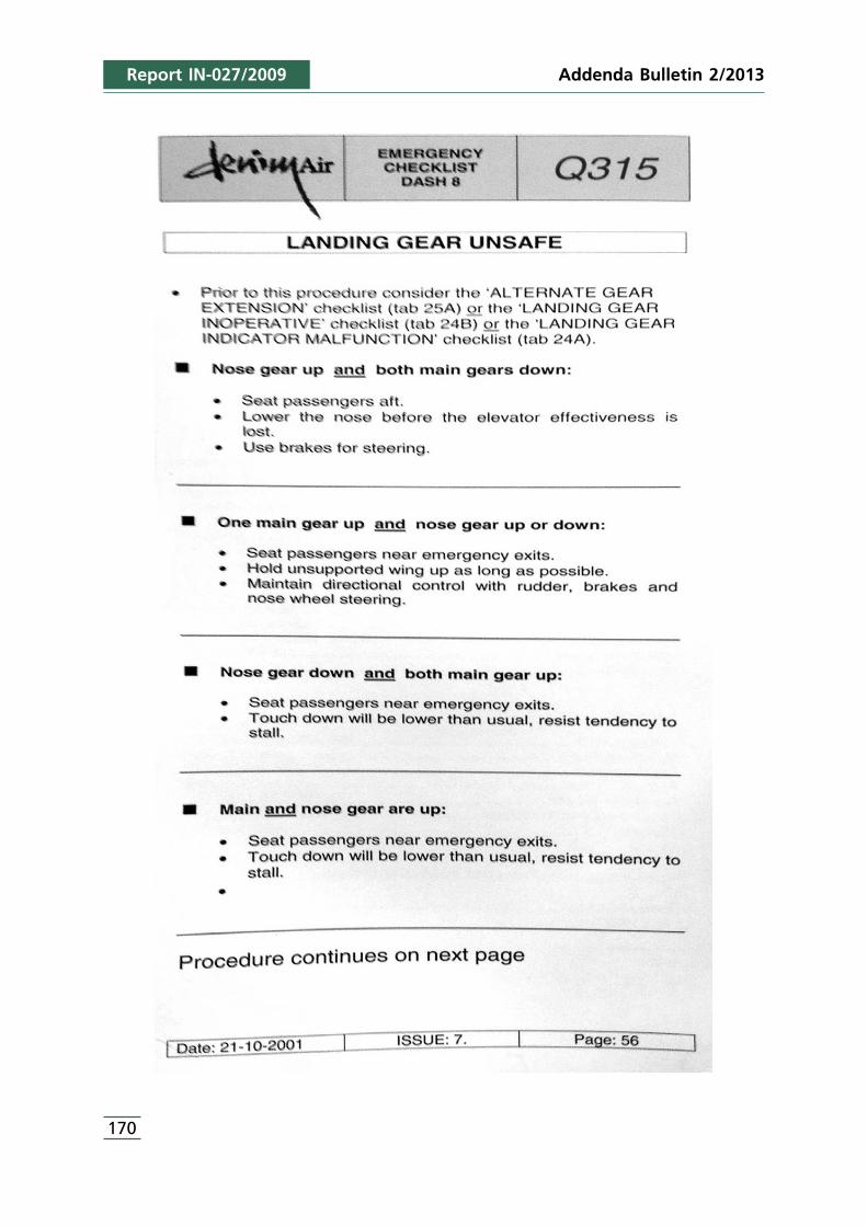
Report IN-027/2009
170
Addenda Bulletin 2/2013
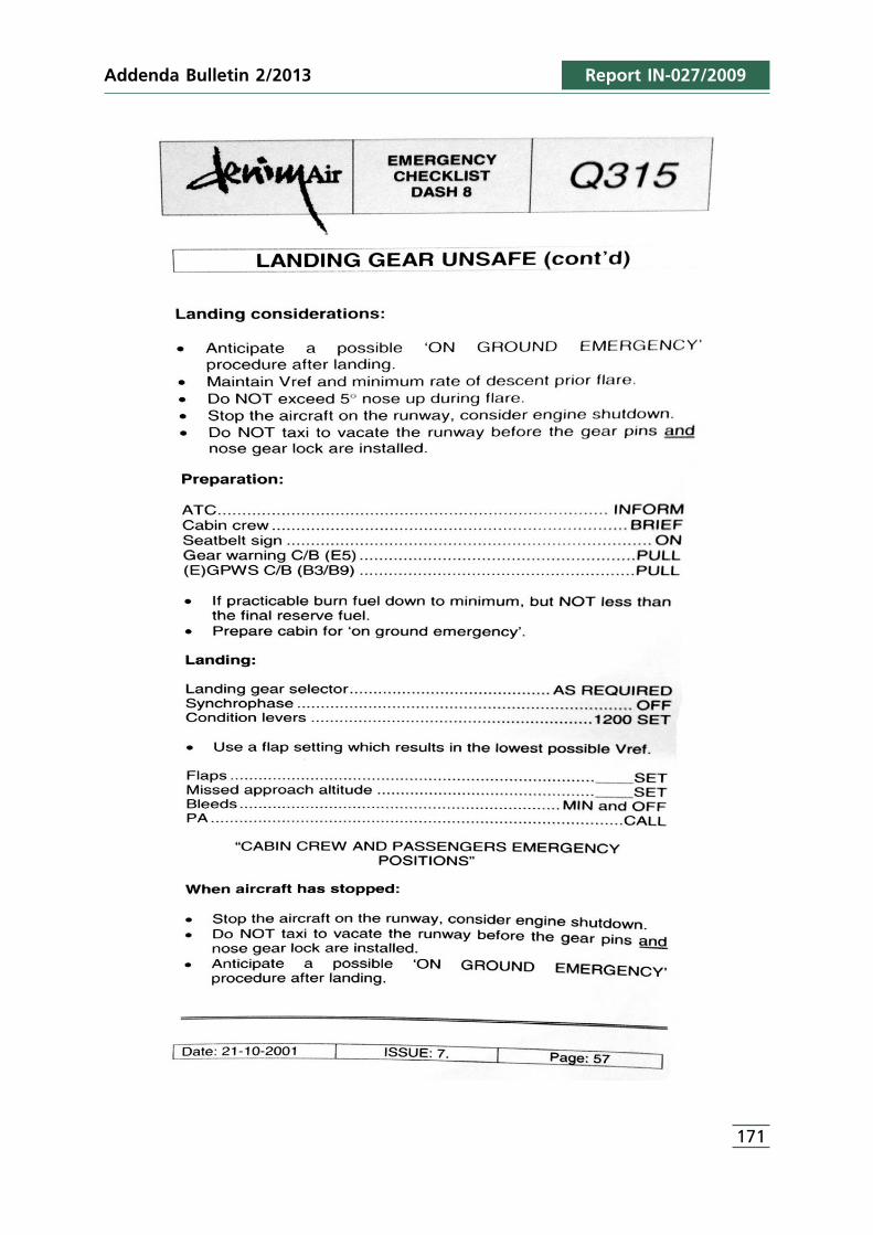
Addenda Bulletin 2/2013 Report IN-027/2009
171

APPENDIX A2“Alternate Gear Extension”Checklist used by Denim Air
173
Report IN-027/2009Addenda Bulletin 2/2013
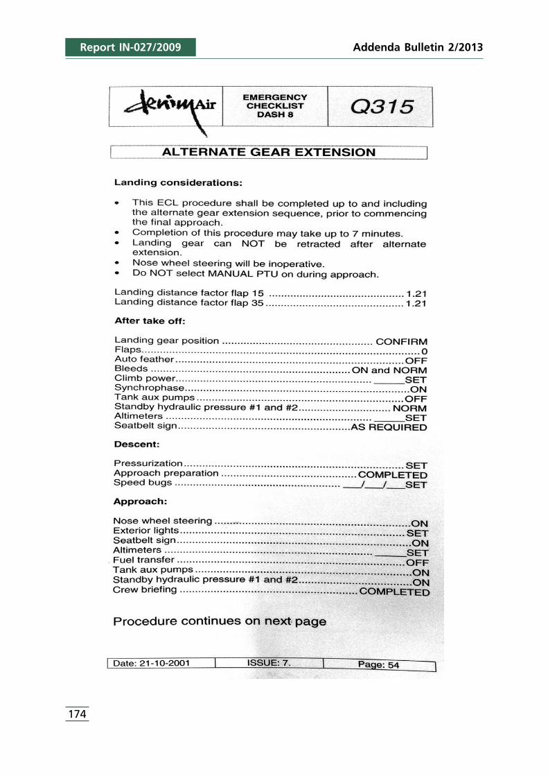
Report IN-027/2009
174
Addenda Bulletin 2/2013
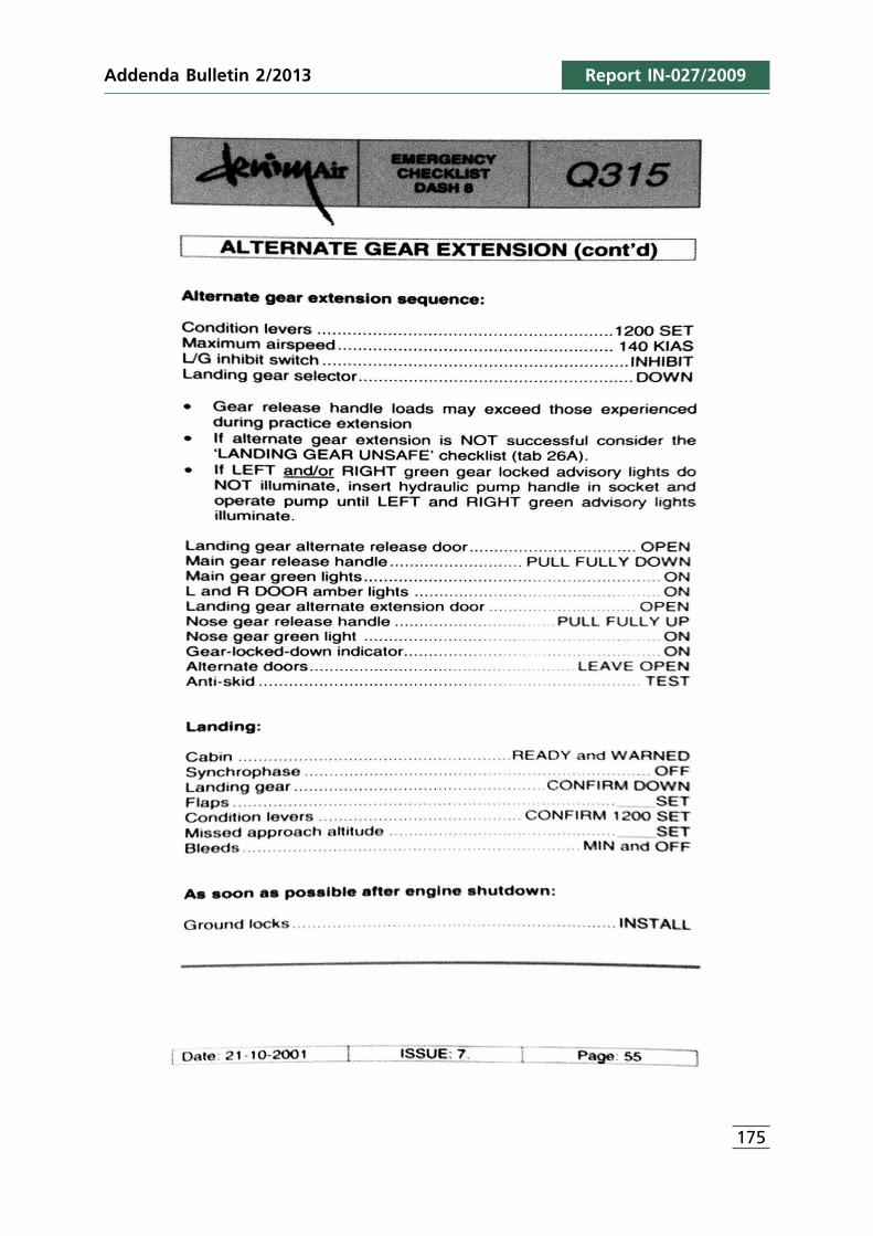
Addenda Bulletin 2/2013 Report IN-027/2009
175

APPENDIX B1“Landing Gear Unsafe”
Checklist used by Air Nostrum
177
Report IN-027/2009Addenda Bulletin 2/2013
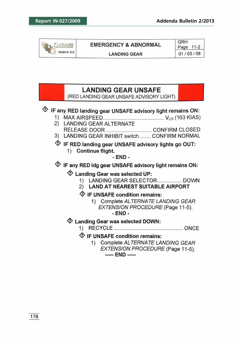
Report IN-027/2009
178
Addenda Bulletin 2/2013
Addenda Bulletin 2/2013 Report IN-027/2009
179
APPENDIX C1Dutch Safety Board Comments
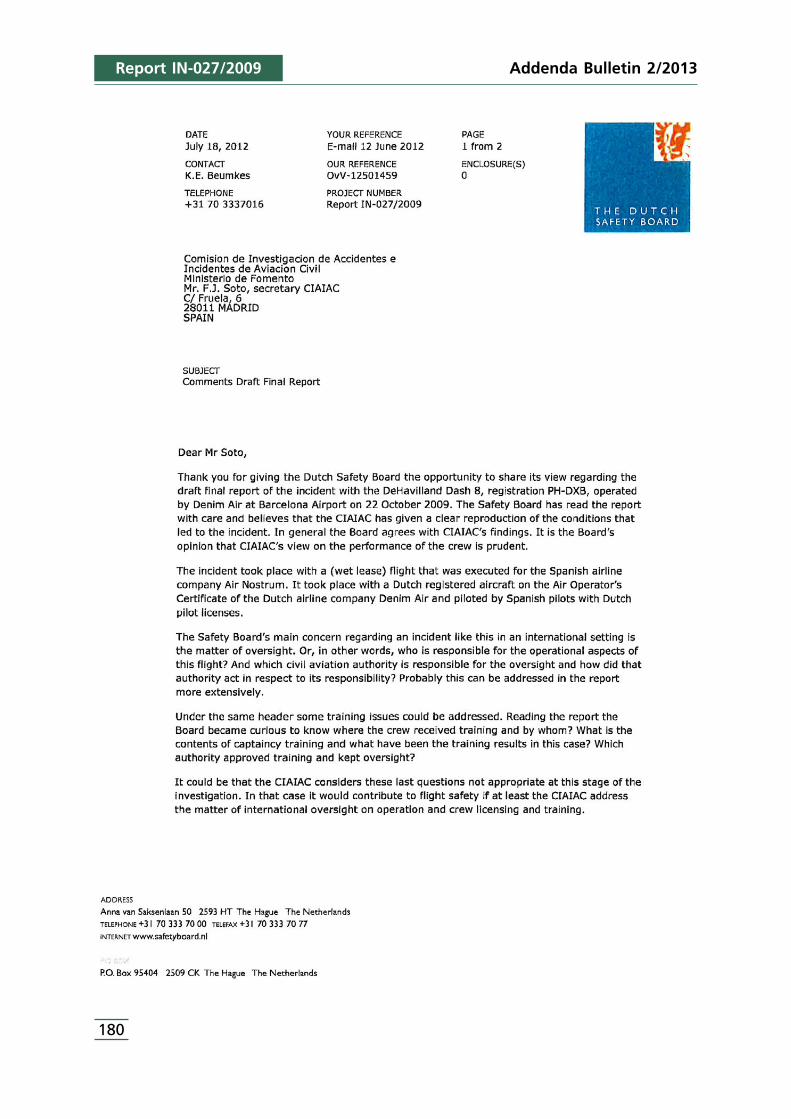
Report IN-027/2009
180
Addenda Bulletin 2/2013
Addenda Bulletin 2/2013 Report IN-027/2009
181

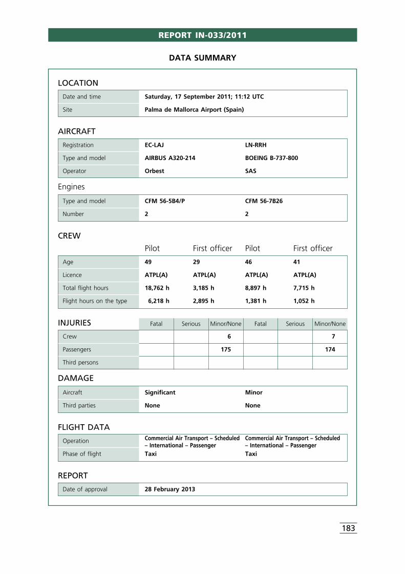
REPORT IN-033/2011
183
LOCATION
Date and time Saturday, 17 September 2011; 11:12 UTC
Site Palma de Mallorca Airport (Spain)
FLIGHT DATACommercial Air Transport – Scheduled Commercial Air Transport – ScheduledOperation– International – Passenger – International – Passenger
Phase of flight Taxi Taxi
REPORT
Date of approval 28 February 2013
CREW
Pilot First officer Pilot First officer
Age 49 29 46 41
Licence ATPL(A) ATPL(A) ATPL(A) ATPL(A)
Total flight hours 18,762 h 3,185 h 8,897 h 7,715 h
Flight hours on the type 6,218 h 2,895 h 1,381 h 1,052 h
AIRCRAFT
Registration EC-LAJ LN-RRH
Type and model AIRBUS A320-214 BOEING B-737-800
Operator Orbest SAS
Engines
Type and model CFM 56-5B4/P CFM 56-7B26
Number 2 2
DATA SUMMARY
INJURIES Fatal Serious Minor/None Fatal Serious Minor/None
Crew 6 7
Passengers 175 174
Third persons
DAMAGE
Aircraft Significant Minor
Third parties None None
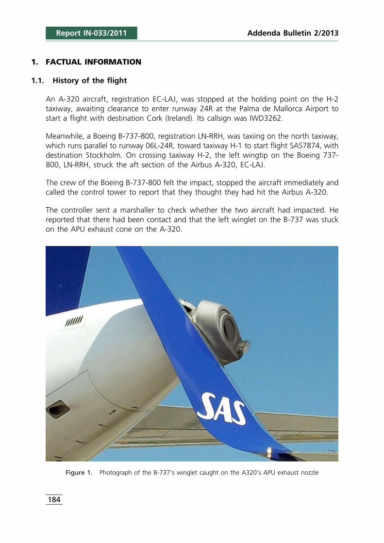
Addenda Bulletin 2/2013
184
1. FACTUAL INFORMATION
1.1. History of the flight
An A-320 aircraft, registration EC-LAJ, was stopped at the holding point on the H-2taxiway, awaiting clearance to enter runway 24R at the Palma de Mallorca Airport tostart a flight with destination Cork (Ireland). Its callsign was IWD3262.
Meanwhile, a Boeing B-737-800, registration LN-RRH, was taxiing on the north taxiway,which runs parallel to runway 06L-24R, toward taxiway H-1 to start flight SAS7874, withdestination Stockholm. On crossing taxiway H-2, the left wingtip on the Boeing 737-800, LN-RRH, struck the aft section of the Airbus A-320, EC-LAJ.
The crew of the Boeing B-737-800 felt the impact, stopped the aircraft immediately andcalled the control tower to report that they thought they had hit the Airbus A-320.
The controller sent a marshaller to check whether the two aircraft had impacted. Hereported that there had been contact and that the left winglet on the B-737 was stuckon the APU exhaust cone on the A-320.
Figure 1. Photograph of the B-737’s winglet caught on the A320’s APU exhaust nozzle
Report IN-033/2011
185
The B-737 was pushed with a tractor to free it from the A-320, after which both aircraftreturned under their own power to the parking stand in order to have the damageevaluated.
1.2. Injuries to persons
There were no injuries.
1.3. Damage to aircraft
The Airbus A320, registration EC-LAJ, suffered damage to the aft part of the fuselagethat required replacing the entire section aft of frame 84, along with the APU exhaustgas pipe and the rail structure holding this part. The firewall on frame 84 also had tobe repaired.
The damage to the Boeing B737, registration LN-RRH, was limited to the leading edgeon the left wing and part of the skin on the left winglet.
1.4. Personnel information
1.4.1. Aircraft EC-LAJ
Captain
Age: 49 years old
Nationality: Spanish
License: ATPL (A), valid until 9/01/2013
Ratings: • A320 valid until 27/07/2012• A330 valid until 27/06/2012• IR valid until 27/07/2012
Class 1 medical certificate: Valid until 18/10/2011
Total flight hours: 18,762 h
Flight hours on the aircraft type: 6,218 h
Duty time in the previous 30 days: 89 h
Duty time in the previous 24 h: 6.3 h
Rest time prior to the flight: 15:44 h
Start of on-duty time: 06:45 h
Report IN-033/2011Addenda Bulletin 2/2013
Addenda Bulletin 2/2013
186
First officer
Age: 29 years old
Nationality: Spanish
License: ATPL (A), valid until 29/03/2015
Ratings: • A320 valid until 16/05/2012• IR valid until 16/05/2012
Class 1 medical certificate: Valid until 25/06/2012
Total flight hours: 3,185:43 h
Flight hours on the aircraft type: 2,895:43 h
Duty time in the previous 30 days: 75:36 h
Duty time in the previous 24 hours: 9:31 h
Rest time prior to the flight: 15:45 h
Start of on-duty time: 06:15 UTC
1.4.2. Aircraft LN-RRH
Captain
Age: 46 years old
Nationality: Swedish
License: ATPL (A), valid until 30/08/2013
Ratings: • B-737 300-900 valid until 31/05/2012• IR/ME/SP valid until 31/05/2012
Class 1 medical certificate: Valid until 21/07/2012
English language competency: Level 6
Total flight hours: 8,897 h
Flight hours on the aircraft type: 1,381 h
Duty time in the previous 30 days: 57 h
Duty time in the previous 24 hours: 4 h
Rest time prior to the flight: 10:35 h
Start of on-duty time: 04:35 UTC
Report IN-033/2011
187
First officer
Age: 41 years old
Nationality: Norwegian
License: ATPL (A), valid until 31/03/2016
Ratings: • B-737 300-900 valid until 31/05/2012• IR/ME/ valid until 31/05/2012
Class 1 medical certificate: Valid until 10/11/2011
English language competency: Level 6
Total flight hours: 7,715 h
Flight hours on the aircraft type: 1,052 h
Duty time in the previous 30 days: 47:46 h
Duty time in the previous 24 hours: 4 h
Rest time prior to the flight: 10:35 h
Start of on-duty time: 04:35 UTC
1.5. Aircraft information
1.5.1. Aircraft EC-LAJ
Type: Airbus
Model: A320-214
Serial number: 3889
Year of manufacture: 2009
Airworthiness review certificate (ARC): Valid until 6/05/2012
Engines, number/type and model: Two (2)/CFM 56-5B4/P
Dry weight: 38,096 kg
Maximum takeoff weight: 77,000 kg
Dimensions: • Wingspan: 34.09 m• Length: 37.57 m• Height: 11.76 m• Wheelbase: 7.59 m
Hours: 6,984:53 h
Cycles: 2,610
Report IN-033/2011Addenda Bulletin 2/2013
Addenda Bulletin 2/2013
188
Last maintenance inspection carried out to the Aircraft was an “A” type (each 750hours) and took placed on 14/09/2011. On that moment the aircraft had 6,905 h.
1.5.2. Aircraft LN-RRH
Type: Boeing
Model: B737-800 (with winglets)
Serial number: 34546
Year of manufacture: 2009
Airworthiness review certificate (ARC): Valid until 2/06/2012
Engines, number/type and model: Two (2) CFM56-7B26
Dry weight: 62,732 kg
Maximum takeoff weight: 78,999 kg
Dimensions: • Wingspan: 35.79 m• Length: 42.1 m• Height: 12.6 m• Wheelbase: 5.70 m
Hours: 6,553.38 h
Cycles: 3,633
Last maintenance inspection carried out to the Aircraft was a “600FH” and took placedon 15/08/2011. On that moment the aircraft had 6,304 h.
1.6. Meteorological information
The Palma de Mallorca Airport 10:30, 11:00 and 11:30 UTC METARs for the day of theincident were as follows:
171030Z 22010KT 9999 FEW025 28/20 Q1017 NOSIG=
171100Z 22011KT 9999 FEW025 28/19 Q1016 NOSIG=
171130Z 22012KT 9999 FEW025 28/19 Q1016 NOSIG=
These reports indicate that at the time of the collision, around 11:15, the wind was from220° at between 11 and 12 kt, the visibility was equal or greater than 10 km, therewere few clouds at 2,500 ft, the temperature was 28°, the dewpoint 19 °C and theQNH was 1016 hPa.
Report IN-033/2011
189
1.7. Aids to navigation
The taxiways located in the area of the incident, North, H-1, H-2 and H-3, havecenterline and edge markings.
The H-1, H-2 and H-3 holding points to runway 24R are indicated using standardmarkings (stop bars) and lights. The markings were in keeping with configuration B,described in 5.2.10 of the Technical Design and Operating Regulations for Public-UseAerodromes published in Royal Decree 862/2009, and in 5.2.10 of ICAO Appendix 14,Volume I.
1.8. Communications
1.8.1. Aircraft EC-LAJ and LN-RRH
The crews of both aircraft established contact with ground movement control (GMC) atthe Palma Airport to receive their respective taxi clearances.
The crew of the A-320 established contact with ground control North (GMC-N) on121.9 MHz at 11:04:04 UTC, reporting that they were at stand 108 ready to taxi.
The controller cleared them to taxi and instructed them to “taxi on E, holding point24R”, which was acknowledged by the crew.
At 11:06:10 the crew of the Boeing B-737 established radio contact with GMC-N torequest taxi instructions. The controller instructed them to taxi via F to the runway 24Rholding point, which the crew correctly acknowledged.
At 11:07:20 the controller called aircraft A-320 to instruct the crew to monitor the118.45 MHz frequency, which corresponds to the control tower – departures (TWR-DEP).
At 11:08:03 the GMC-N controller called the B-737 crew to inform them that they werenumber 1 ahead of the Monarch airplane on the North taxiway. The crewacknowledged “number one ahead of the Monarch”.
At 11:09:51 the GMC-N controller once again called the aircraft to instruct the crew tomonitor the 118.45 MHz frequency (TWR-DEP).
There were no further communications until the crew called TWR-DEP at 11:12:46 toreport that they thought they had struck another aircraft’s tail. The controller askedthem to repeat the information, to which the crew replied that they had hit the tail ofthe Spanish Airbus that was at the holding point. The controller instructed them to hold
Report IN-033/2011Addenda Bulletin 2/2013
1 This part of the conversation was garbled.
Addenda Bulletin 2/2013
190
their position and that they were number four behind the Spanish airplane. The crewstated that they would hold their position.
Immediately afterwards, at 11:13:24, the crew of the Airbus A-320 called TWR-DEP toreport they were at H-2 and had felt a strong knock to the rear of the airplane andasked the controller if he could confirm whether they had been hit.
The controller replied, “uhh, the BER and the SAS... they came close but I didn’t thinkthey’d hit you, uh, could it have been the SAS?”
The A-320 crew replied that the airplane had moved considerably but they did not knowwhether it had been due to contact or jet blast.
The controller then asked the SAS B-737 crew to report its position. The crew repliedthat they were almost at “A...”1 but that they thought they had hit the tail of theairplane to their left, an Orbest.
The controller acknowledged the information and requested their current position, towhich the crew of the B-737 replied that they were at H-2, just behind the Airbus.
The controller then informed the crews of both airplanes that he was sending amarshaller to check on the situation.
1.8.2. Other aircraft
The aircraft with callsign TOM9FT was cleared to taxi to the runway 24R holding pointvia gate E at 10:59:39.
Seconds later the controller cleared an aircraft with callsign TOM19K to taxi to therunway 24R holding point via gate G.
At around 11:04:00, the ground controller instructed both aircraft to contact TWR-DEPon 118.45 MHz.
At 11:07:40 the controller called aircraft MON875 to inform its crew that they werenumber two behind the SAS. This aircraft was transferred to TWR-DEP at 11:09:51.
At 11:08:06 the TWR-DEP controller called aircraft TOM19K to clear them to enter therunway and line up. They were cleared to take off at 11:10:45, with the takeoff takingplace at 11:12:00.
Report IN-033/2011
191
At 11:10:59 the controller cleared aircraft TOM9FT to take off behind TOM19K.TOM9FT took off at 11:16:10, after the impact between the two other aircraft hadtaken place.
Neither of these aircraft was cleared by the control tower to use taxiway H-1 nor werethey assigned a specific holding point.
1.9. Aerodrome information
1.9.1. Airfield configuration
The ICAO classification of the Palma de Mallorca Airport is 4-E.
It has two parallel runways, 06R-24L and 06L-24R. The incident took place at the accessto the 24R threshold.
Parallel to the 06L-24R runway is a taxiway called “North”. The separation betweentheir centerlines is 200 m. Access to the 24R threshold from this taxiway is via threeconnecting taxiways called H-1, H-2 and H-3. The 24R threshold is displaced 70 m.
The “North” taxiway is 23 meters wide and has centerline and edge markings.
In the ICAO aerodrome map for ground movements, west configuration, “AD 2-LEPAGMC 1.2”, featured in the AIP Spain, the hot spots are identified by circles from thetaxi point of view. Only one area is identified in taxiway “North”, which is at theintersection of the “North” and “Link” taxiways, and which is far away from the areawhere the incident took place.
The control tower at the Palma de Mallorca Airport is situated near the air side of theterminal building. Its location is such that it could be said that it is located at thegeographic center of the airport. The straight-line distance from the control tower tothe area of the incident is about 1,700 m. As a result, the position of aircraft in therunway 24R holding area is difficult to discern from the control room.
In the first half of 2007, a study was carried out to identify physical hazards at theairport. This study detected that aircraft stopped at the H-1 and H-2 holding pointswould violate the (obstacle limitation) surface to the runway 24R approach (the H-3 holdpoint did not affect the obstacle limitation surfaces). This hazard was classified as“tolerable”.
While hazards with this classification are tolerable in this condition, mitigation measuresshould be taken so as to reduce risk levels as much as is reasonably possible, thoughgiven their risk level, the corrective actions need not be carried out immediately.
Report IN-033/2011Addenda Bulletin 2/2013
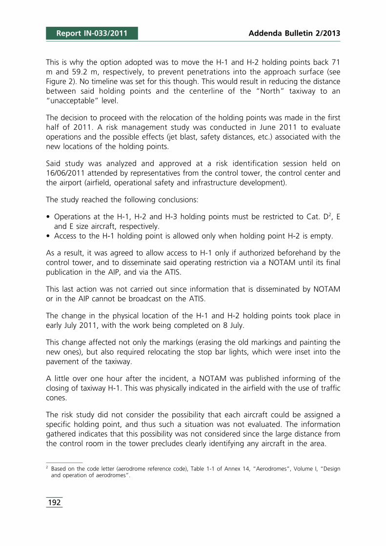
2 Based on the code letter (aerodrome reference code), Table 1-1 of Annex 14, “Aerodromes”, Volume I, “Designand operation of aerodromes”.
Addenda Bulletin 2/2013
192
This is why the option adopted was to move the H-1 and H-2 holding points back 71m and 59.2 m, respectively, to prevent penetrations into the approach surface (seeFigure 2). No timeline was set for this though. This would result in reducing the distancebetween said holding points and the centerline of the “North” taxiway to an“unacceptable” level.
The decision to proceed with the relocation of the holding points was made in the firsthalf of 2011. A risk management study was conducted in June 2011 to evaluateoperations and the possible effects (jet blast, safety distances, etc.) associated with thenew locations of the holding points.
Said study was analyzed and approved at a risk identification session held on16/06/2011 attended by representatives from the control tower, the control center andthe airport (airfield, operational safety and infrastructure development).
The study reached the following conclusions:
• Operations at the H-1, H-2 and H-3 holding points must be restricted to Cat. D2, Eand E size aircraft, respectively.
• Access to the H-1 holding point is allowed only when holding point H-2 is empty.
As a result, it was agreed to allow access to H-1 only if authorized beforehand by thecontrol tower, and to disseminate said operating restriction via a NOTAM until its finalpublication in the AIP, and via the ATIS.
This last action was not carried out since information that is disseminated by NOTAMor in the AIP cannot be broadcast on the ATIS.
The change in the physical location of the H-1 and H-2 holding points took place inearly July 2011, with the work being completed on 8 July.
This change affected not only the markings (erasing the old markings and painting thenew ones), but also required relocating the stop bar lights, which were inset into thepavement of the taxiway.
A little over one hour after the incident, a NOTAM was published informing of theclosing of taxiway H-1. This was physically indicated in the airfield with the use of trafficcones.
The risk study did not consider the possibility that each aircraft could be assigned aspecific holding point, and thus such a situation was not evaluated. The informationgathered indicates that this possibility was not considered since the large distance fromthe control room in the tower precludes clearly identifying any aircraft in the area.
Report IN-033/2011
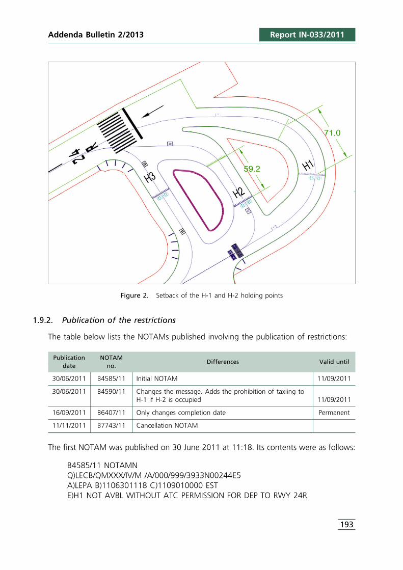
193
Figure 2. Setback of the H-1 and H-2 holding points
1.9.2. Publication of the restrictions
The table below lists the NOTAMs published involving the publication of restrictions:
Publication NOTAMdate no.
Differences Valid until
30/06/2011 B4585/11 Initial NOTAM 11/09/2011
30/06/2011 B4590/11 Changes the message. Adds the prohibition of taxiing toH-1 if H-2 is occupied 11/09/2011
16/09/2011 B6407/11 Only changes completion date Permanent
11/11/2011 B7743/11 Cancellation NOTAM
The first NOTAM was published on 30 June 2011 at 11:18. Its contents were as follows:
B4585/11 NOTAMNQ)LECB/QMXXX/IV/M /A/000/999/3933N00244E5A)LEPA B)1106301118 C)1109010000 ESTE)H1 NOT AVBL WITHOUT ATC PERMISSION FOR DEP TO RWY 24R
Report IN-033/2011Addenda Bulletin 2/2013
Addenda Bulletin 2/2013
194
Which briefly means that from 11:18 on 30/06/2011 until 00:00 on 01/09/2011, H1was not available at the Palma de Mallorca Airport without permission from ATC fordepartures from runway 24R.
The code in the subject line is MXXX which, according to ICAO Doc. 8126, correspondsto movement and landing area – taxiways – others. The purpose qualifier is M(miscellaneous).
This NOTAM was replaced on the same day by another that only modified the restrictionas follows: H1 not available without ATC permission for traffic departing from runway24R. Aircraft waiting to take off from runway 24R cannot taxi to H1 if H2 is occupied.
On 16/09/2011 at 07:30, a new NOTAM was published that replaced the old one andintroduced a change with regard to its expiration date, making it permanent (PERM).
Finally, NOTAMC B7743/11 was published on 11/11/2011, which cancelled NOTAMRB6407/11, since its information had been included in Airac AMDT 09/11.
It should be noted that this NOTAM (B6407/11) was issued on 16/09/2011 to replaceNOTAM B4590/11, which contained the following information in item “C”, referring tothe end of the activity: 1109010000 EST. This means that the estimated completion datewas 01/09/2011 at 00:00.
Item 6 in Appendix A to Chapter 6 of the Aeronautical Information Services Manual,ICAO doc. 8126, contains the following instruction: “Any NOTAM which includes an“EST” must be cancelled or replaced before the date-time specified in item C.” If aNOTAM is not cancelled or replaced before its estimated completion date, however, itis not automatically invalidated, since that would require the replacement or cancellationof the NOTAM.
1.9.3. Process of publishing the closing of taxiway H-1
At 12:23 on 17/09/2011, that is, one hour and 20 minutes after the incident, a newNOTAM was published informing of the closing of taxiway H-1 until 19/09/2011. Its textwas as follows:
B6449/11 NOTAMNQ)LECB/QMXLC/IV/NBO/A/000/999/3933N00244E5A)LEPA B)1109171223 C)1109191200 ESTE)TWY H-1 CLSD
At 06:30 on 19/09/2011, NOTAMR B6457/11 was published to replace the previousone, B6449/11, that only modified the qualifier in the “purpose” line from NBO to M.
Report IN-033/2011
195
At 09:15 on that same day, another NOTAMR was published to replace the one issuedat 06:30, extending its duration until 23:59 on 31/10/2011.
This NOTAMR was replaced on several occasions, the text of the last one being asshown below, which extends the duration of the taxiway closing until 31/03/2012.
(B0286/12 NOTAMR B8074/11Q)LECB/QMXLC/IV/M /A /AGA/000/999/3933N00244E5A)LEPA B)1201131809 C)1203312359 ESTE)TWY H-1 CLSD.)
The closing of the taxiway was eventually indicated with physical markings.
1.9.4. Other NOTAMs
A search was conducted at another airport of NOTAMs dealing with similar matters inan effort to compare their codings. The Tenerife South Airport was chosen at random,with three of its NOTAMs shown below:
B7593/11 NOYTAMR B5536/11Q)GCCC/QMPLC/IV/BO/A/000/999/2803N01634W5A)GCTS B)1111071309 C)1202072359 ESTD)0000-0800 18002359E) ACFT STANDS E-29, E-30, E-31, E-32, J-33, J-34, J-35, I-8A, I-9, H-10, I-11, I-11A AND J-12 CLOSED)
As Item E) indicates, this NOTAM involves the closing of specific parking stands.According to Appendix B of Chapter 6 of ICAO Doc. 8126, the code MP means “aircraftstands” and LC means “closed”. According to this same document, this codecorresponds to “BO” as the qualifier in the “purpose” field.
B7599/11 NOYTAMR B5535/11Q)GCCC/QMXLC/IV/M/A/000/999/2803N01634W5A)GCTS B)1111071357 C)1202072359D)NOV 07 1800-2359, NOV 08-30 0000-0800 1800-2359, DEC 01-31 0000-08001800-2359, JAN 01-31 0000-0800 1800-2359, FEB 01-07 0000-0800 1800-2359E) TWY INNER BTN I-9 AND J-12 CLOSED)
This NOTAM refers to the closing of the “inner” taxiway between I-9 and J-12 atspecific dates and times. The MX code means “taxiways” and LC “closed”,corresponding to an “M” qualifier in the “purpose” field.
B8492/11 NOYTAMR B6236/11Q)GCCC/QMAXX/IV/NBO/A/000/999/2803N01634W5A)GCTS B)1112071116 C)1203070600 ESTE)TAXIING BTN HOLDING POINT A2-2 AND TWY B1 NOT ALLOWED))
Report IN-033/2011Addenda Bulletin 2/2013
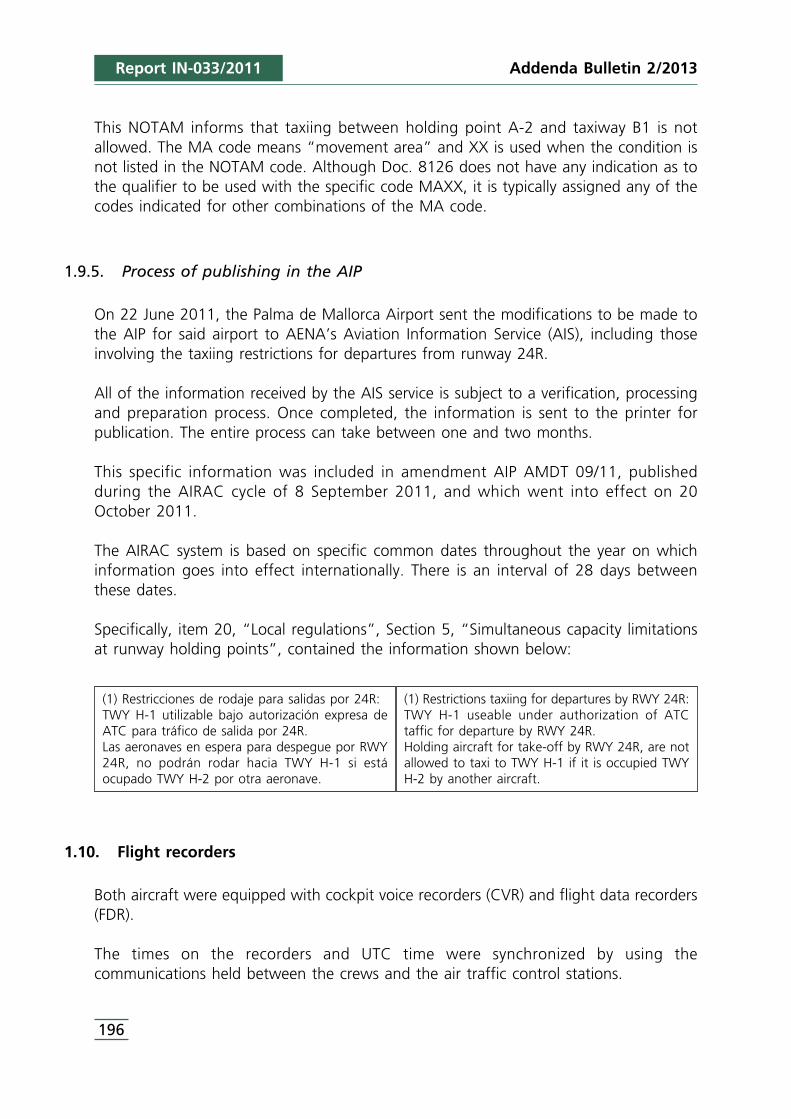
Addenda Bulletin 2/2013
196
This NOTAM informs that taxiing between holding point A-2 and taxiway B1 is notallowed. The MA code means “movement area” and XX is used when the condition isnot listed in the NOTAM code. Although Doc. 8126 does not have any indication as tothe qualifier to be used with the specific code MAXX, it is typically assigned any of thecodes indicated for other combinations of the MA code.
1.9.5. Process of publishing in the AIP
On 22 June 2011, the Palma de Mallorca Airport sent the modifications to be made tothe AIP for said airport to AENA’s Aviation Information Service (AIS), including thoseinvolving the taxiing restrictions for departures from runway 24R.
All of the information received by the AIS service is subject to a verification, processingand preparation process. Once completed, the information is sent to the printer forpublication. The entire process can take between one and two months.
This specific information was included in amendment AIP AMDT 09/11, publishedduring the AIRAC cycle of 8 September 2011, and which went into effect on 20October 2011.
The AIRAC system is based on specific common dates throughout the year on whichinformation goes into effect internationally. There is an interval of 28 days betweenthese dates.
Specifically, item 20, “Local regulations”, Section 5, “Simultaneous capacity limitationsat runway holding points”, contained the information shown below:
1.10. Flight recorders
Both aircraft were equipped with cockpit voice recorders (CVR) and flight data recorders(FDR).
The times on the recorders and UTC time were synchronized by using thecommunications held between the crews and the air traffic control stations.
(1) Restrictions taxiing for departures by RWY 24R:TWY H-1 useable under authorization of ATCtaffic for departure by RWY 24R.Holding aircraft for take-off by RWY 24R, are notallowed to taxi to TWY H-1 if it is occupied TWYH-2 by another aircraft.
(1) Restricciones de rodaje para salidas por 24R:TWY H-1 utilizable bajo autorización expresa deATC para tráfico de salida por 24R.Las aeronaves en espera para despegue por RWY24R, no podrán rodar hacia TWY H-1 si estáocupado TWY H-2 por otra aeronave.
Report IN-033/2011
197
1.10.1. Aircraft EC-LAJ
1.10.1.1. Cockpit voice recorder (CVR)
The aircraft was equipped with a four-channel Honeywell 980-6022-001 cockpit voicerecorder (CVR), S/N CVR120-12798. Channels 1, 2 and 3, lasting 30 minutes each,record the signals from the crew’s communications microphones. The fourth channelrecords sounds from the area microphone and lasts 2 hours.
The recorder was downloaded at the CIAIAC’s laboratory. The audio information onchannels 1, 2 and 3 was of high quality, while that on channel 4 was of mediumquality.
The information on channels 1, 2 and 3 was post-incident, since the CVR continuedrecording after the incident for more than 30 minutes, thus taping over the previousinformation.
Channel 4, by virtue of its longer duration (2 hours), did contain information from bothbefore and after the incident.
The information recorded during the interval from the moment the CVR started torecord at the beginning of the flight until five minutes after the event was transcribed.
The table below shows a summary of the conversations of most relevance to theincident during this time period. All times are in UTC and were obtained bysynchronizing the conversations held with ATC.
Time Source Contents
11:03:01 CPT If we’re clear let’s start 2.
11:03:46 CPT All right, number 2 engine started ok.
11:03:56 CPT Starting 1.
11:04:00 FO Taxi?
11:04:00 CPT Yes, request taxi, lest someone else...
11:04:04 FO Good day, Iberworld 3262 at 108 ready to taxi.
11:04:10 FO Via echo holding point 24 right Iberworld 3262.
11:07:20 TWR Iberworld 3263 monitor 118.45, have a good flight.
11:07:23 FO 118.45, thank you, good service, good day.
11:07:29 CPT One’s gone, there’s the Thomas Cook and two Thomsons left.
11:07:39 FO Two 75s (Boeing B757).
11:08:42 CPT There’s one more in front. There’s three.
Report IN-033/2011Addenda Bulletin 2/2013
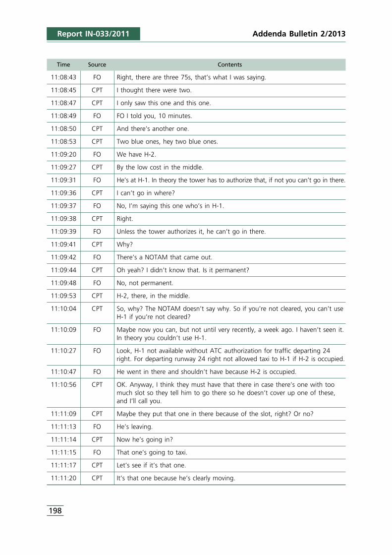
Addenda Bulletin 2/2013
198
Time Source Contents
11:08:43 FO Right, there are three 75s, that’s what I was saying.
11:08:45 CPT I thought there were two.
11:08:47 CPT I only saw this one and this one.
11:08:49 FO FO I told you, 10 minutes.
11:08:50 CPT And there’s another one.
11:08:53 CPT Two blue ones, hey two blue ones.
11:09:20 FO We have H-2.
11:09:27 CPT By the low cost in the middle.
11:09:31 FO He’s at H-1. In theory the tower has to authorize that, if not you can’t go in there.
11:09:36 CPT I can’t go in where?
11:09:37 FO No, I’m saying this one who’s in H-1.
11:09:38 CPT Right.
11:09:39 FO Unless the tower authorizes it, he can’t go in there.
11:09:41 CPT Why?
11:09:42 FO There’s a NOTAM that came out.
11:09:44 CPT Oh yeah? I didn’t know that. Is it permanent?
11:09:48 FO No, not permanent.
11:09:53 CPT H-2, there, in the middle.
11:10:04 CPT So, why? The NOTAM doesn’t say why. So if you’re not cleared, you can’t useH-1 if you’re not cleared?
11:10:09 FO Maybe now you can, but not until very recently, a week ago. I haven’t seen it.In theory you couldn’t use H-1.
11:10:27 FO Look, H-1 not available without ATC authorization for traffic departing 24right. For departing runway 24 right not allowed taxi to H-1 if H-2 is occupied.
11:10:47 FO He went in there and shouldn’t have because H-2 is occupied.
11:10:56 CPT OK. Anyway, I think they must have that there in case there’s one with toomuch slot so they tell him to go there so he doesn’t cover up one of these,and I’ll call you.
11:11:09 CPT Maybe they put that one in there because of the slot, right? Or no?
11:11:13 FO He’s leaving.
11:11:14 CPT Now he’s going in?
11:11:15 FO That one’s going to taxi.
11:11:17 CPT Let’s see if it’s that one.
11:11:20 CPT It’s that one because he’s clearly moving.
Report IN-033/2011
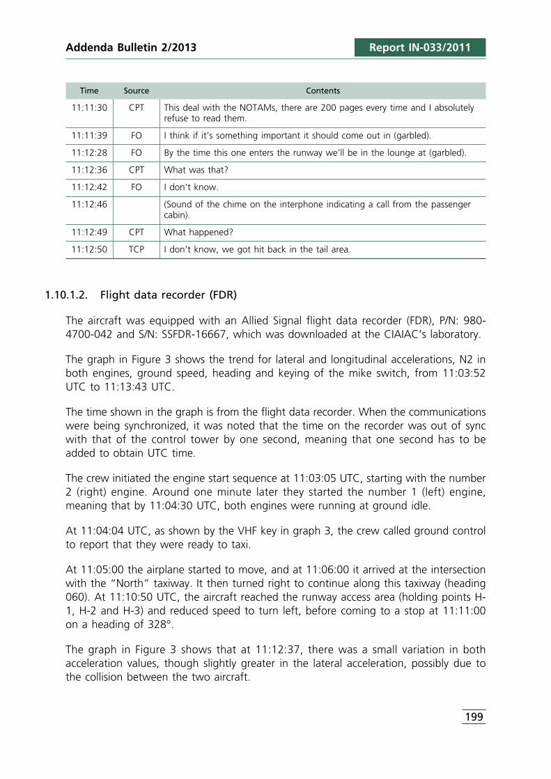
199
Time Source Contents
11:11:30 CPT This deal with the NOTAMs, there are 200 pages every time and I absolutelyrefuse to read them.
11:11:39 FO I think if it’s something important it should come out in (garbled).
11:12:28 FO By the time this one enters the runway we’ll be in the lounge at (garbled).
11:12:36 CPT What was that?
11:12:42 FO I don’t know.
11:12:46 (Sound of the chime on the interphone indicating a call from the passengercabin).
11:12:49 CPT What happened?
11:12:50 TCP I don’t know, we got hit back in the tail area.
1.10.1.2. Flight data recorder (FDR)
The aircraft was equipped with an Allied Signal flight data recorder (FDR), P/N: 980-4700-042 and S/N: SSFDR-16667, which was downloaded at the CIAIAC’s laboratory.
The graph in Figure 3 shows the trend for lateral and longitudinal accelerations, N2 inboth engines, ground speed, heading and keying of the mike switch, from 11:03:52UTC to 11:13:43 UTC.
The time shown in the graph is from the flight data recorder. When the communicationswere being synchronized, it was noted that the time on the recorder was out of syncwith that of the control tower by one second, meaning that one second has to beadded to obtain UTC time.
The crew initiated the engine start sequence at 11:03:05 UTC, starting with the number2 (right) engine. Around one minute later they started the number 1 (left) engine,meaning that by 11:04:30 UTC, both engines were running at ground idle.
At 11:04:04 UTC, as shown by the VHF key in graph 3, the crew called ground controlto report that they were ready to taxi.
At 11:05:00 the airplane started to move, and at 11:06:00 it arrived at the intersectionwith the “North” taxiway. It then turned right to continue along this taxiway (heading060). At 11:10:50 UTC, the aircraft reached the runway access area (holding points H-1, H-2 and H-3) and reduced speed to turn left, before coming to a stop at 11:11:00on a heading of 328°.
The graph in Figure 3 shows that at 11:12:37, there was a small variation in bothacceleration values, though slightly greater in the lateral acceleration, possibly due tothe collision between the two aircraft.
Report IN-033/2011Addenda Bulletin 2/2013
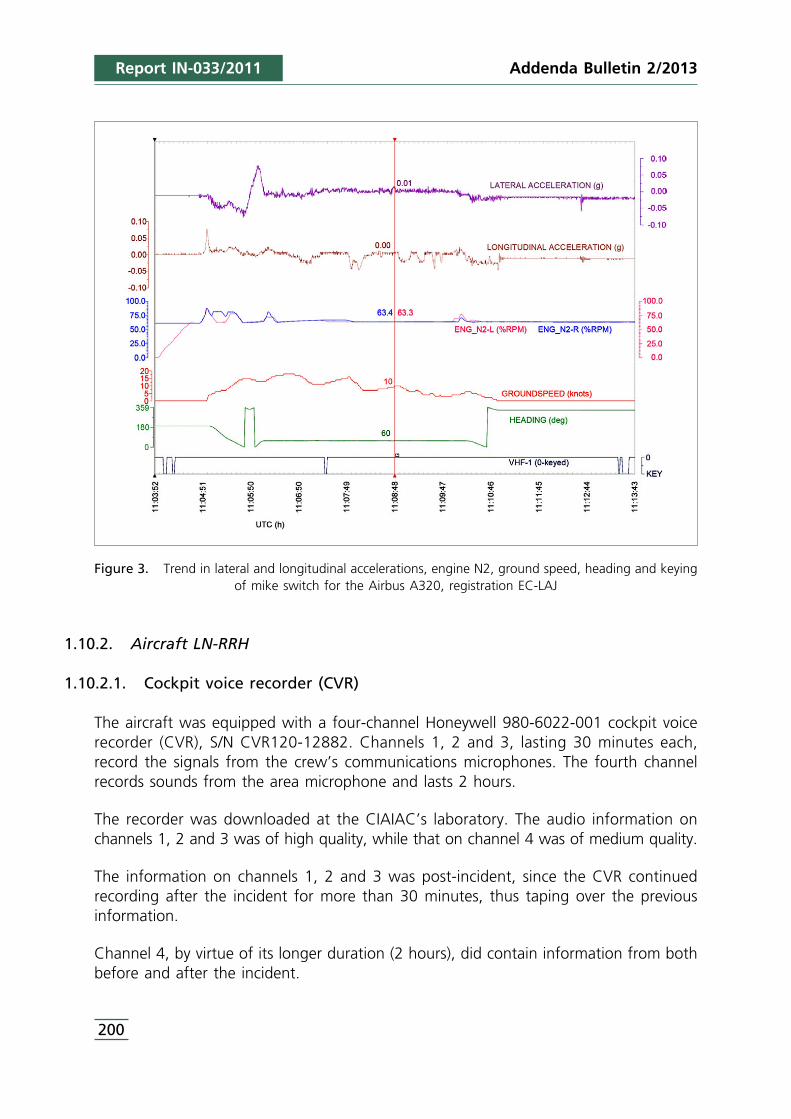
Addenda Bulletin 2/2013
200
Figure 3. Trend in lateral and longitudinal accelerations, engine N2, ground speed, heading and keyingof mike switch for the Airbus A320, registration EC-LAJ
1.10.2. Aircraft LN-RRH
1.10.2.1. Cockpit voice recorder (CVR)
The aircraft was equipped with a four-channel Honeywell 980-6022-001 cockpit voicerecorder (CVR), S/N CVR120-12882. Channels 1, 2 and 3, lasting 30 minutes each,record the signals from the crew’s communications microphones. The fourth channelrecords sounds from the area microphone and lasts 2 hours.
The recorder was downloaded at the CIAIAC’s laboratory. The audio information onchannels 1, 2 and 3 was of high quality, while that on channel 4 was of medium quality.
The information on channels 1, 2 and 3 was post-incident, since the CVR continuedrecording after the incident for more than 30 minutes, thus taping over the previousinformation.
Channel 4, by virtue of its longer duration (2 hours), did contain information from bothbefore and after the incident.
Report IN-033/2011
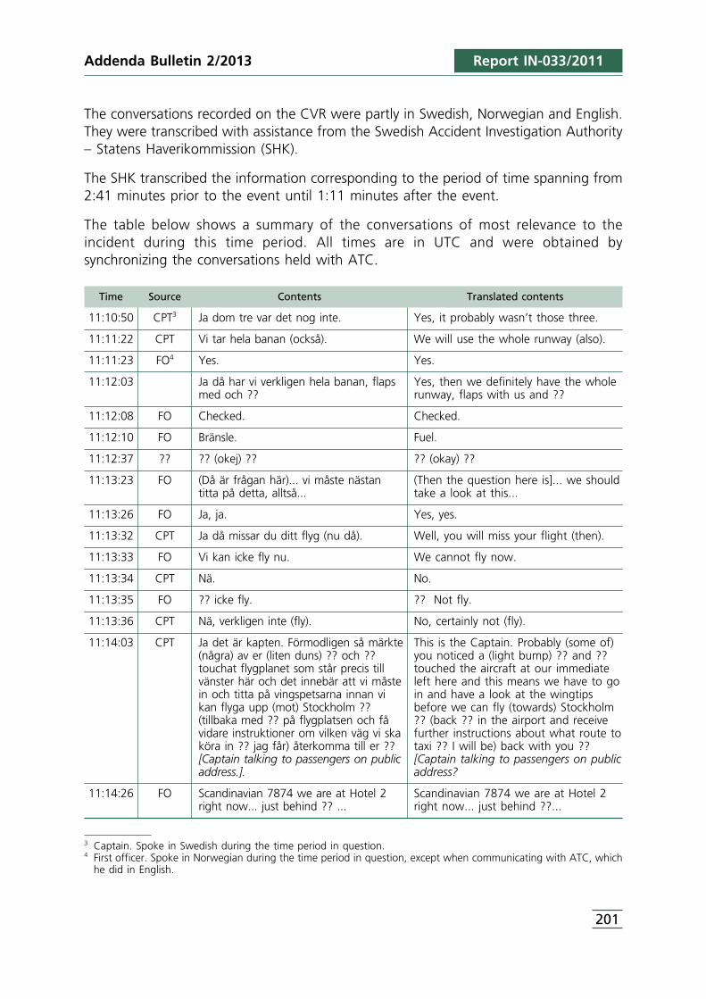
3 Captain. Spoke in Swedish during the time period in question.4 First officer. Spoke in Norwegian during the time period in question, except when communicating with ATC, which
he did in English.
201
The conversations recorded on the CVR were partly in Swedish, Norwegian and English.They were transcribed with assistance from the Swedish Accident Investigation Authority– Statens Haverikommission (SHK).
The SHK transcribed the information corresponding to the period of time spanning from2:41 minutes prior to the event until 1:11 minutes after the event.
The table below shows a summary of the conversations of most relevance to theincident during this time period. All times are in UTC and were obtained bysynchronizing the conversations held with ATC.
Time Source Contents Translated contents
11:10:50 CPT3 Ja dom tre var det nog inte. Yes, it probably wasn’t those three.
11:11:22 CPT Vi tar hela banan (också). We will use the whole runway (also).
11:11:23 FO4 Yes. Yes.
11:12:03 Ja då har vi verkligen hela banan, flaps Yes, then we definitely have the wholemed och ?? runway, flaps with us and ??
11:12:08 FO Checked. Checked.
11:12:10 FO Bränsle. Fuel.
11:12:37 ?? ?? (okej) ?? ?? (okay) ??
11:13:23 FO (Då är frågan här)... vi måste nästan (Then the question here is]... we shouldtitta på detta, alltså... take a look at this...
11:13:26 FO Ja, ja. Yes, yes.
11:13:32 CPT Ja då missar du ditt flyg (nu då). Well, you will miss your flight (then).
11:13:33 FO Vi kan icke fly nu. We cannot fly now.
11:13:34 CPT Nä. No.
11:13:35 FO ?? icke fly. ?? Not fly.
11:13:36 CPT Nä, verkligen inte (fly). No, certainly not (fly).
11:14:03 CPT Ja det är kapten. Förmodligen så märkte This is the Captain. Probably (some of)(några) av er (liten duns) ?? och ?? you noticed a (light bump) ?? and ??touchat flygplanet som står precis till touched the aircraft at our immediatevänster här och det innebär att vi måste left here and this means we have to goin och titta på vingspetsarna innan vi in and have a look at the wingtipskan flyga upp (mot) Stockholm ?? before we can fly (towards) Stockholm(tillbaka med ?? på flygplatsen och få ?? (back ?? in the airport and receivevidare instruktioner om vilken väg vi ska further instructions about what route toköra in ?? jag får) återkomma till er ?? taxi ?? I will be) back with you ??[Captain talking to passengers on public [Captain talking to passengers on publicaddress.]. address?
11:14:26 FO Scandinavian 7874 we are at Hotel 2 Scandinavian 7874 we are at Hotel 2right now... just behind ?? ... right now... just behind ??...
Report IN-033/2011Addenda Bulletin 2/2013
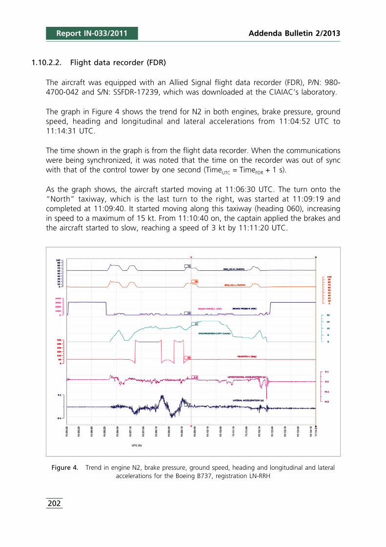
Addenda Bulletin 2/2013
202
1.10.2.2. Flight data recorder (FDR)
The aircraft was equipped with an Allied Signal flight data recorder (FDR), P/N: 980-4700-042 and S/N: SSFDR-17239, which was downloaded at the CIAIAC’s laboratory.
The graph in Figure 4 shows the trend for N2 in both engines, brake pressure, groundspeed, heading and longitudinal and lateral accelerations from 11:04:52 UTC to11:14:31 UTC.
The time shown in the graph is from the flight data recorder. When the communicationswere being synchronized, it was noted that the time on the recorder was out of syncwith that of the control tower by one second (TimeUTC = TimeFDR + 1 s).
As the graph shows, the aircraft started moving at 11:06:30 UTC. The turn onto the“North” taxiway, which is the last turn to the right, was started at 11:09:19 andcompleted at 11:09:40. It started moving along this taxiway (heading 060), increasingin speed to a maximum of 15 kt. From 11:10:40 on, the captain applied the brakes andthe aircraft started to slow, reaching a speed of 3 kt by 11:11:20 UTC.
Figure 4. Trend in engine N2, brake pressure, ground speed, heading and longitudinal and lateralaccelerations for the Boeing B737, registration LN-RRH
Report IN-033/2011
5 SAS flight dispatch/planning.
203
They continued moving slowly for a little under a minute. The speed then increasedslightly and, about 20 seconds later, the captain applied the brakes and slowed theaircraft to 2-3 kt.
As the graph in Figure 4 shows, there was a slight variation at 11:12:37 in the lateraland longitudinal acceleration values, followed immediately by a significant increase inbrake pressure resulting in the stopping of the aircraft.
Seconds earlier there had been a small variation (increase) in the aircraft’s heading,indicative of a slight turn to the right.
1.11. Organizational and management information
1.11.1. Scandinavian Airlines (SAS)
Flight preparation
The flight was planned on the morning of the day of the incident prior to takeoff fromStockholm using the “RODOS” flight planning system. All of the available route andaerodrome information was compiled, though no information was found involvingtaxiing restrictions on the taxiways or runway 24R holding points at the Palma deMallorca Airport.
The RODOS system relies on Eurocontrol’s AIS database as its universal NOTAM provider.
This system has a pre-programmed “pilot” filter that uses the Q code on NOTAMs,specifically the second and third letters, to automatically detect and highlight any newNOTAM that is relevant to the crews. It also uses the “purpose” field such that onlythose NOTAMs with the N, B or O qualifiers are routed to the crews.
This filter was designed based on those aspects that SAS pilots and flight dispatchersthought would be relevant to operations.
Specifically, the code for the second and third letters in the Palma de Mallorca NOTAM,MX, is one of the codes that is used by the filter.
The system also utilizes another criterion based on the qualifier field such that thoseNOTAMs with an M are filtered out, since those, based on the definition of thatqualifier, are regarded as involving miscellaneous topics that are unsuitable for inclusionin pre-flight information bulletins, unless they are specifically required.
Any new NOTAM that is automatically highlighted (not filtered) by the system is thenevaluated by the CPHOW5 so as to eliminate any information that is of no operationalrelevance to the pilots.
Report IN-033/2011Addenda Bulletin 2/2013
Addenda Bulletin 2/2013
204
The NOTAMs with the taxiing restrictions for holding points H-1 and H-2 were codedQMXXX, and the “purpose” field had an M. As noted earlier, the RODOS systemautomatically filters out any NOTAMs containing an M in the “purpose” field, which iswhy the flight dispatch information given to the crew did not include NOTAM B6407/11.
Taxi procedures
OM-A 8.4.1.2.3 states that “an airplane will not normally taxi closer than 1/4 of theaircraft’s wingspan to any obstacle”.
It also notes the PNF’s responsibility to inform the PF whenever the airplane is going totaxi closer than 1/4 of the wingspan to any obstacle located on his side. It also statesthat taxi markings do not always ensure adequate obstacle clearance and thus must beused with caution.
The aircraft’s wingtips are clearly visible from either the left or right seat in the cockpit.
1.11.2. Orbest
Flight preparation
This operator does not have a system to filter NOTAMs, meaning that the flight crewsreceive any published NOTAMs that affect or could affect the flight planned, that is,those involving the departure, destination and alternate aerodromes as well as theplanned flight path.
The operator acknowledges that this forces crews to review a very high number ofNOTAMs prior to every flight. While this ensures that crews will receive all of thenecessary information, the inordinately high volume of information might lead to a non-adequate assessment for them.
1.11.3. AENA
Royal Decree 905/1991 of 14 June, which approved the statute of the Spanish airportauthority AENA (Spanish Airports and Air Navigation), assigns AENA the task ofproviding aeronautical information services, among others.
The aeronautical information service (AIS) is provided by AENA through the AIS Office.
The structure, organization and responsibilities of the AIS office are contained in the AISoperations manual, V 3.0, published by AENA, according to which, the AIS officeconsists of three divisions:
Report IN-033/2011
205
• AIS (central air navigation services).• The international NOTAM office (NOF), which is part of the central air navigation
services.• The aeronautical information office (AIO) and/or the air traffic services reporting
offices (ARO) of airports and control centers.
New proposed NOTAMs are drafted by the affected departments (airports, controlcenters, etc.) and then sent from the AIO/ARO at these centers to the internationalNOTAM office (NOF).
The NOF’s responsibilities include verifying and approving, if appropriate, the proposedNOTAMs received from the AIS/ARO and other authorized departments and agenciesfor subsequent distribution as NOTAMs.
1.12. Additional information
1.12.1. Aeronautical Information Services regulations
Aeronautical information services on an international level are regulated by ICAO Annex15, Aeronautical Information Services, by ICAO Doc. 8126, Aeronautical InformationServices Manual and by ICAO Doc. 8400, ICAO Abbreviations and Codes.
Doc. 8126 has information on the contents of the fields as well as on the codes forNOTAMs.
Doc. 8400 is the reference document that contains the abbreviations to be used in theNOTAMs.
Among the aspects regulated by the above documents are those involving NOTAMs.
Nationally, Royal Decree 57/2002 of 18 January, which approved the Air TrafficRegulation, and specifically Book VIII, regulates the aeronautical information service.Chapter 5 of said book is devoted to NOTAMs and contains instructions on issuing anddistributing NOTAMs, along with general specifications.
The AIS Procedures Manual, V3.0, published by AENA, has more specific instructions onNOTAMs.
To code NOTAMs, ICAO Doc. 8126, Aeronautical Information Services Manual, must beused.
Appendix B in Doc. 8126 has a category index based on the second letter that classifiesthem into five main groups: AGA (aerodromes, air routes and ground aids), CNS
Report IN-033/2011Addenda Bulletin 2/2013
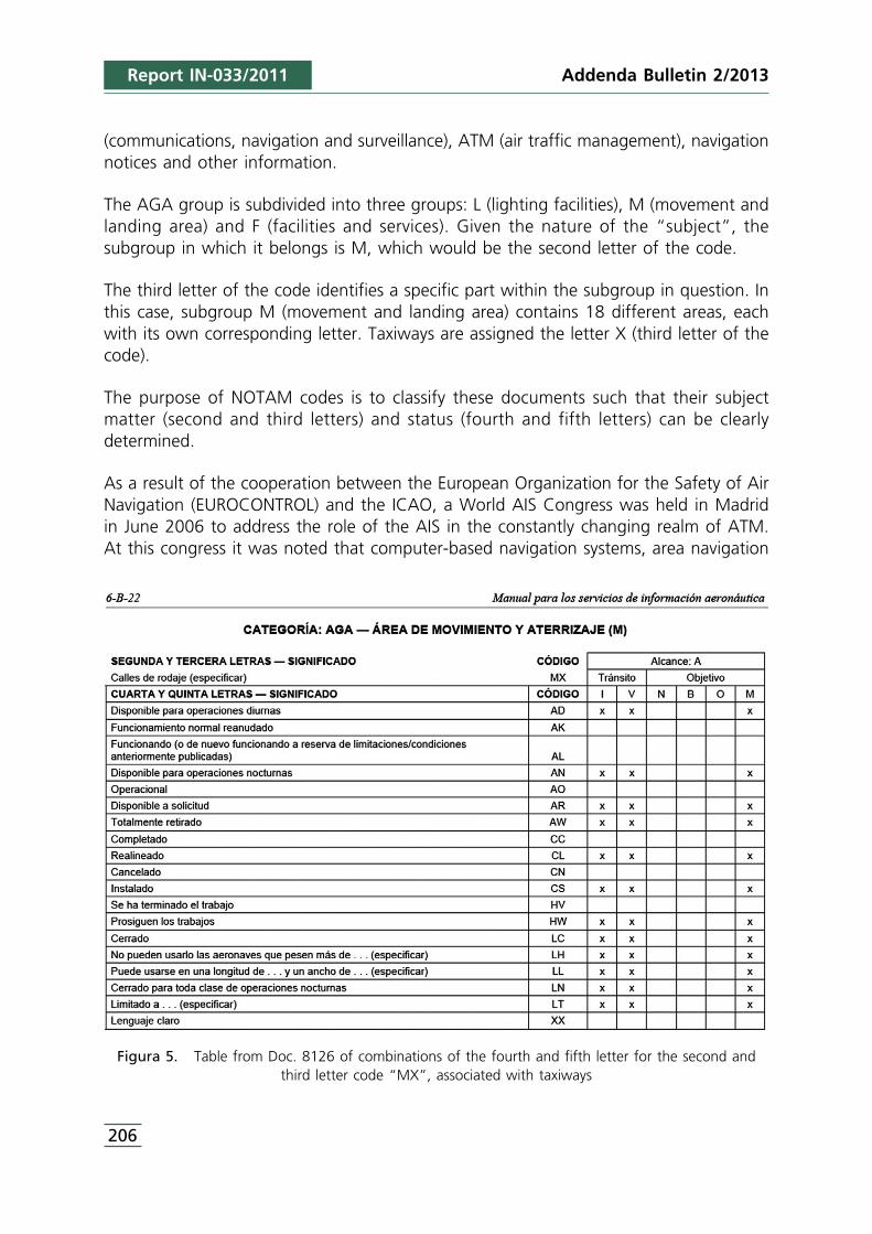
Addenda Bulletin 2/2013
206
(communications, navigation and surveillance), ATM (air traffic management), navigationnotices and other information.
The AGA group is subdivided into three groups: L (lighting facilities), M (movement andlanding area) and F (facilities and services). Given the nature of the “subject”, thesubgroup in which it belongs is M, which would be the second letter of the code.
The third letter of the code identifies a specific part within the subgroup in question. Inthis case, subgroup M (movement and landing area) contains 18 different areas, eachwith its own corresponding letter. Taxiways are assigned the letter X (third letter of thecode).
The purpose of NOTAM codes is to classify these documents such that their subjectmatter (second and third letters) and status (fourth and fifth letters) can be clearlydetermined.
As a result of the cooperation between the European Organization for the Safety of AirNavigation (EUROCONTROL) and the ICAO, a World AIS Congress was held in Madridin June 2006 to address the role of the AIS in the constantly changing realm of ATM.At this congress it was noted that computer-based navigation systems, area navigation
Figura 5. Table from Doc. 8126 of combinations of the fourth and fifth letter for the second andthird letter code “MX”, associated with taxiways
Report IN-033/2011
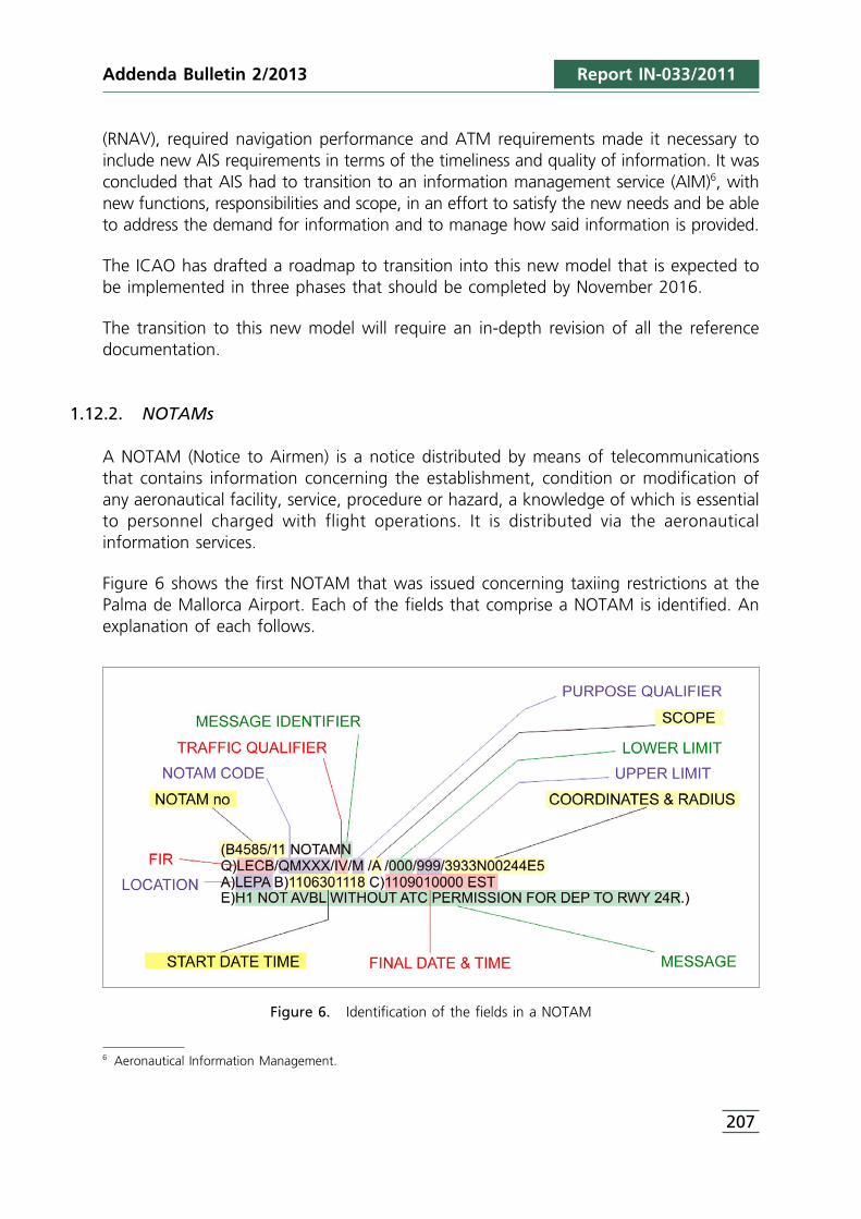
6 Aeronautical Information Management.
207
(RNAV), required navigation performance and ATM requirements made it necessary toinclude new AIS requirements in terms of the timeliness and quality of information. It wasconcluded that AIS had to transition to an information management service (AIM)6, withnew functions, responsibilities and scope, in an effort to satisfy the new needs and be ableto address the demand for information and to manage how said information is provided.
The ICAO has drafted a roadmap to transition into this new model that is expected tobe implemented in three phases that should be completed by November 2016.
The transition to this new model will require an in-depth revision of all the referencedocumentation.
1.12.2. NOTAMs
A NOTAM (Notice to Airmen) is a notice distributed by means of telecommunicationsthat contains information concerning the establishment, condition or modification ofany aeronautical facility, service, procedure or hazard, a knowledge of which is essentialto personnel charged with flight operations. It is distributed via the aeronauticalinformation services.
Figure 6 shows the first NOTAM that was issued concerning taxiing restrictions at thePalma de Mallorca Airport. Each of the fields that comprise a NOTAM is identified. Anexplanation of each follows.
Figure 6. Identification of the fields in a NOTAM
Report IN-033/2011Addenda Bulletin 2/2013
Addenda Bulletin 2/2013
208
NOTAM no. Indicates the NOTAM series and number.
Message identifier. After the word NOTAM one of the following letters is used; N ifit includes new information, R if it replaces a previous NOTAM, or C if it cancels aprevious NOTAM.
FIR. Indicates the FIR to which the information contained in the NOTAM applies.
NOTAM code. Consists of five letters, the first of which is always Q. The second andthird letters identify the subject and the fourth and fifth its status or condition, asdescribed in Doc. 8400, ICAO Abbreviations and Codes, and in Appendix B of ICAODoc. 8126, Aeronautical Information Services Manual. The letters MX signify“movement and landing area, taxiways”. The fourth and fifth letters, XX, mean “other”.
Traffic qualifier. Refers to the type of traffic that may be affected by the NOTAM.In this case it would be instrumental (I) and visual (V).
Purpose qualifier. This is the “purpose” field. There are five qualifiers, N, B, O, Mand K, whose meanings are:
• N, NOTAM selected for the immediate attention of aircraft operators.• B, NOTAM selected for pre-flight information bulletin (PIB) entry.• O, NOTAM concerning flight operations.• M, Miscellaneous NOTAM; not subject for a briefing, but it is available on request.• K, NOTAM is a checklist.
This field can contain the following qualifier combinations: K, B, BO, NBO or M.Appendix B to ICAO Doc. 8126, Aeronautical Information Services Manual, has guidanceon combinations of “purpose” qualifiers depending on the subject and the content ofthe NOTAM (code). The table included in page 6-B-22 of this manual contains the codefor this subject, MXXX, though it does not define any qualifiers for this code.
Scope. May refer to an aerodrome (A), en route (E), nav warning (W) or checklist (K).In this case it is aerodrome.
Lower limit. If the subject does not contain specific height information, 000 will beused for the lower limit.
Upper limit. If the subject does not contain specific height information, 999 will beused for the lower limit.
Coordinates and radius. Indicates the coordinates and the radius of influence in NM.If the scope of the NOTAM is “A”, insert the coordinates of the aerodrome referencepoint.
Report IN-033/2011
209
Location. ICAO location indicator of the place to which the information applies.
Start date and time. Indicates the date and time at which the event begins.
End date and time. Indicates the date and time at which the event ends. The code“EST” indicates that the duration is estimated. If the information is permanent, “PERM”is used.
Message. This is called the text field and it contains the information to bedisseminated. It typically uses the abbreviations listed in ICAO Doc. 8400, ICAOAbbreviations and Codes.
1.12.3. Statements
The crew members of the SAS aircraft were not interviewed in person and submittedtheir statements in writing.
SAS – Commander
The planning for the round trip flight between Stockholm and Palma de Mallorca wasnormal. The information available did not show any unusual circumstances. The flightto Palma was normal.
The stopover in Palma, as well as the activities prior to the return flight, proceedednormally and they were ready to depart before the scheduled time.
They were cleared to taxi to runway 24R via I7, F. When they started taxiing, theyrequested and obtained confirmation for the clearance.
There was a lot of traffic that day on the apron, so they taxied slowly. There was nopressure from GMC. While taxiing on the North taxiway, they changed the radiofrequency to that of the control tower.
He seems to recall that as they were arriving at the runway 24R holding area, there wasan airplane at H-3 and an Orbest A320 at H-2. Since the mass of the airplane wasrelatively high, he wanted to use the full length of runway 24R, meaning he had toaccess it via H-1.
He steered the aircraft toward H-1 and upon passing by H-3, the first officer asked ifthey could make it. He immediately realized he was referring to the A320 that was atH-2, so he turned slightly to the right and turned his head left to look at the wingtipon that side. He estimated they had enough room to pass. The aircraft’s speed was very
Report IN-033/2011Addenda Bulletin 2/2013
Addenda Bulletin 2/2013
210
low, on the order of 2-3 kt. They immediately realized that the left wingtip had struckthe A320 and quickly stopped the aircraft. They then called the control tower to reportthe incident.
They communicated with the A320 crew on the control tower frequency and askedthem to remain where they were, not to turn on the APU and to turn off their rightengine, since its jet blast was directed in their direction.
SAS – First officer
He concurred with the captain that the flight to Palma and the preparations for thereturn flight to Stockholm proceeded normally.
After being pushed back from stand 46, they requested taxi clearance from groundcontrol (GMC), who authorized them to taxi via F and hold at 24R.
They maneuvered carefully on the apron since there was a lot of traffic and requestedconfirmation from GMC whether to use I-7 and then F, which GMC confirmed.
As they were arriving at the intersection with the North taxiway, he saw anotherairplane, a Monarch, taxiing to their left. GMC confirmed that they were number 1.They turned right to continue on the North taxiway to the runway 24R holding point,and he changed the radio frequency to that of the control tower.
As they were arriving at the runway 24R holding point, he saw that there was anotheraircraft stopped at the H-3 holding point, a TUI Boeing 757, and another airplane, anOrbest A320, stopped at H-2. Also, another aircraft had just left H-1 and lined up onthe runway.
As they were passing by H-3, the captain stated his intention to continue toward H-1.He thought they would stop before reaching H-2 because of the airplane occupying it,but when he realized they were not stopping, he asked the captain if they could makeit.
Their taxi speed was very low and the captain slowed even more, turning slightly to theright to move further away from the other aircraft, looking outside and saying, “we canmake it”.
Seconds later he felt the airplane move slightly as the left wingtip struck the tail of theA320, after which the captain immediately stopped the aircraft.
He heard on the radio how the crew from another airplane, possibly the Monarchbehind them, reported “SK you hit them”.
Report IN-033/2011
211
1.12.4. Measures taken by AENA
The first measure adopted was to close taxiway H-1, as noted earlier in point 1.9.3.
Following the incident the airport evaluated the event, identifying several points thatwere deemed to require corrective actions. These points are summarized below.
• Improve the procedure for tracking the implementation of risk mitigation measures forthe dual purpose of monitoring and evaluating the effectiveness of the mitigationmeasures adopted, and anticipating the possibility that when, for whatever reason, anyof the planned measures cannot be implemented, the situation be reevaluated andalternative safety measures established that guarantee an acceptable level of safety.
• Any situation that entails important operational changes at the airport must haveinput from pilots.
• Propose the installation of a system to monitor and record operations in themovement areas, especially at thresholds.
• Any action involving a change in runway or taxi configuration will preferably becarried out during the low season and must be planned as far in advance as possible,unless prevented by the urgency of the action.
1.12.5. Measures taken by Scandinavian Airlines (SAS)
SAS revised its operations manual so as to emphasize the importance of having crewsmaintain the minimum safety distances while taxiing. Also included in this documentwere instructions to clarify the differences that exist in regard to minimum distancesbetween taxiing to access a paring stand and a standard taxi procedure.
1.12.6. Measures taken by Orbest
Orbest is studying the viability of implementing a NOTAM filtering system.
2. ANALYSIS
2.1. Situation at the runway 24R holding point
At 11:08:06, the controller authorized TOM19K to enter the runway and at 11:10:45to take off. Then, at 11:10:56, he informed TOM9FT that it was cleared to take offbehind TOM19K.
The conversations recorded on the CVR of aircraft EC-LAJ reveal that as the aircraft wasarriving at the runway 24R holding area, holding points H-1 and H-3 were occupied,
Report IN-033/2011Addenda Bulletin 2/2013
Addenda Bulletin 2/2013
212
since they said, “we have H-2, by the low cost in the middle”, and seconds later thefirst officer added, “he’s at H-1”.
From these same conversations we can infer that TOM19K started entering the runwayat 11:11:13.
The communications held with the various control stations also reveal that none of theaircraft was directed or cleared to a specific holding point; rather, it was their crewswho decided the holding point through which they would enter the runway, possiblybased on the situation at the time of their arrival at the holding area.
Three conclusions can be drawn from this: the crew of TOM19K was not aware of thetaxiing restriction in effect for holding point H-1; there were no markings or signs inthat part of the airfield that hinted at the existence of the restriction; and the controllerswho were in the tower did not realize that there were aircraft using H-1.
2.2. Taxi phase of aircraft LN-RRH
Based on the findings detailed in the previous section, and on the information from therecorder in aircraft LN-RRH, it can be determined that at the time aircraft TOM19Kstarted moving from the holding point at H-1 to enter the runway, aircraft LN-RRH wason the “North” taxiway within 100 m of the holding area. From that position the crewcould see perfectly well that aircraft TOM19K was entering the runway from holdingpoint H-1, as the pilot stated (see Section 1.13.3).
The H-2 and H-3 holding points were being occupied by EC-LAJ and TOM9FT.
Thus, when the aircraft arrived at the runway 24R holding area, only holding point H-1 was available, as it had just been vacated by TOM19K, which was on the runway.
In such a situation, the typical way to proceed is as was done by the crew of aircraftLN-RRH, namely to head for the recently vacated holding point, which is the only onethat was unoccupied. Moreover, this decision was further conditioned by the fact thatthe aircraft’s weight was relatively high, so it was logical for the crew to try to enterthe runway via H-1, which made the full length of the runway available to them.
By the time they were at H-2 they should have noticed the very little clearance availableto pass behind the aircraft that was in that holding point, as manifested by the firstofficer’s question, “Can we make it?”
At that moment it should have been obvious that the clearance was less than 1/4 ofthe aircraft’s wingspan, as evidenced by the slight turn to the right made by the pilot,perhaps in an effort to increase the separation between the two aircraft. According to
Report IN-033/2011
213
OM-A 8.4.1.2.3, “an airplane will not normally taxi closer than 1/4 of the aircraft’swingspan to any obstacle”, thus the crew should not have continue taxiing.
2.3. Planning of the relocation of the holding points
Although it was known as early as 2007 that the obstacle limitation surfaces were beingviolated as a result of the location of the H-1 and H-2 holding points, more than fouryears elapsed (until the first half of 2011) before any actions were taken to correct saidviolation.
The study to identify the risks associated with moving the H-1 and H-2 holding pointswas conducted in June 2011, with the physical displacement of these two holdingpoints being carried out in the first two weeks of the following month.
It is worth noting that four years passed without any corrective action being taken tocorrect the violation of the obstacle clearance surfaces before suddenly, in 2011 and inthe span of one month, a risk assessment was conducted, the information to bepublished in the AIP was written and sent to the AIS, and a NOTAM was publishedinforming of the restriction, since there was no time to disseminate the information viathe AIP before the holding points were physically moved. Also of note is the fact thatthe work itself was carried out during the high season, despite the high seasonality ofthe Palma de Mallorca Airport, which would seem to indicate that it would have beenpreferable for the work to have been carried out in the low season.
In light of how the events played out, the impression is that the planning was somewhathasty, possibly due to the importance given to the execution at the expense of theplanning.
This is perhaps why a program to monitor the mitigation measures planned in the riskidentification study or to ensure that the restrictions were published (NOTAM/AIP) wasnot implemented.
As regards this last point, an examination of the way in which the publication of theNOTAMs involving the restriction were published is warranted. NOTAM B4590/11 waspublished on 30/06/2011, whose estimated validity was extended until 01/09/2011. ThisNOTAM was replaced by B6407/11, which was published on 16/09/11, that is, 16 daysafter the supposed expiration of the previous NOTAM.
Although in light of the above information it may seem that NOTAM B4590/11 expired,and thus ceased to be valid on 01/09/2011, it must be noted that a NOTAM with anestimated validity remains valid and active until it is replaced or cancelled. Therefore, onthe day of the incident, the restriction contained in said NOTAM was fully in effect.
Report IN-033/2011Addenda Bulletin 2/2013
Addenda Bulletin 2/2013
214
This circumstance, however, was also in violation of the instructions contained in ICAODoc. 8126, which states that “any NOTAM which includes an “EST” shall be cancelledor replaced before the date-time specified in Item C)”. This violation occurred in alllikelihood due to improper planning that failed to implement a mechanism to track thepublication of the information.
The measures adopted by the Palma de Mallorca Airport, listed in 1.13.4, are consideredto be adequate to address the deficiencies detected by the investigation into thisincident in terms of the planning and tracking of activities.
2.4. Risk evaluation
The study to identify the risks inherent in moving the holding points involved anexhaustive examination of operations with the holding points at their new locations andcorrectly concluded that said location posed a high risk for collisions between aircraft.
The same study determined the measures to be taken to mitigate this risk, and whichprimarily entailed restricting access to H-1 if there was an aircraft at H-2.
The study did not analyze the situation further and did not assess the effectiveness ofthe way in which the corrective measures were implemented.
It is worthwhile to note the factors that had or could have had an influence in thisregard:
1. The H-1 taxi restrictions were not physically evident to the crews of aircraft taxiingin that area.
2. The control tower did not assign aircraft to specific holding points.3. It is impossible to see from the control tower which holding point is being used by
an aircraft.4. The restriction had not yet been distributed via the AIP.5. The restriction had only been made public through a NOTAM.6. The corrective measures were not tracked, which meant that the risk arising from
not implementing a measure (broadcast via ATIS) was not identified, and that noalternative measures could be taken. This deficiency has already been identified byairport management, which has taken steps to ensure that in the future, correctivemeasures are properly tracked.
7. Non-involvement from airline representatives. Had they been involved, the suitabilityof the mitigation measures taken could have been more properly evaluated.
In conclusion, by not broadcasting the restriction on ATIS, its implementation reliedsolely on dissemination via the NOTAM, there being no additional safety measures inplace, thus making for a rather weak implementation.
Report IN-033/2011
215
This conclusion is reinforced by the fact that in the brief period of time analyzed in thisreport, at least one other aircraft in addition to the one involved in the incident taxiedto H-1 without its crew being aware of the restriction and without there being anymechanism that could have alerted them to it.
This incident also indicates that the NOTAM used to broadcast this information waseither not received or was not properly handled by the crews.
2.5. Coding of NOTAMs
Although none of the documents indicated in 1.13.1 clearly specifies how the“subject” should be classified, whether according to the nature of the event or to theplace where it takes place, a close examination of the category listing contained inAppendix B of Doc. 8126, Chapter 6, reveals that the classification should be basedon the location.
The “subject” of the event analyzed in this report involved the “North” taxiway at thePalma de Mallorca Airport, meaning it fell under the AGA classification category.
The code corresponding to the “MX” as the second and third letters allows thecombinations of fourth and fifth letters shown in the table in Figure 5. If the conditionof the “subject” is not listed in the table, then XX are used as the fourth and fifthletters. In this particular case none of the conditions adequately reflects the conditionof the “subject”, which was the taxi restrictions in this area, so the use of the code XXis regarded as appropriate.
Doc. 8126 contains the category AGA – Movement area and landing (M), a combinationwith the A as the third letter (MA), called “movement area”, the application of whichdoes not seem to be sufficiently clear.
ICAO Annex 14 defines “movement area” as “That part of an aerodrome to be usedfor the takeoff, landing and taxiing of aircraft, consisting of the maneuvering area andthe apron(s).”
Based on this, it seems that the taxiways or any other part of the movement area couldbe coded using the combination of the specific second and third letters correspondingto it, MX for taxiways, or MA for a generic movement area. Specifically, the subjectmatter of the case analyzed herein could have been coded as MXXX or MAXX.
Although the ICAO documentation, specifically Doc. 8126, should not be regarded asmere guides for drafting NOTAMs, this should not keep the information and instructionsthey contain from being as unambiguous as possible, since this would serve to improveand standardize the coding of NOTAMs.
Report IN-033/2011Addenda Bulletin 2/2013
Addenda Bulletin 2/2013
216
As for the “traffic” and “purpose” fields, the table in Figure 5 includes information onthe codes to assign to these fields for every combination of the fourth and fifth letters.It is noteworthy that all possible “states” for the taxiways are assigned the purpose“M”, corresponding to miscellaneous. If, however, the subject had been coded as MA,as described in the above paragraph, the corresponding purpose, according to Doc.8126, would be N, B, O.
It is noteworthy that, for example, the “MK” combination for the second and thirdletters, corresponding to movement and landing area – parking area, was mainly assignedthe purpose qualifiers “O” and “B”. Thus, for example, the closing of a parking stand,knowledge of which is not vital to crews since parking stands are assigned by the airport,would be assigned a more important operational category (B and O qualifiers) than ataxiway restriction, the existence of which can only be known through a NOTAM since,as in the case at hand, it is not something that is physically recognizable nor is it theobject of instructions or information provided by the control tower.
Based on the above, the restriction affecting taxiways H-1 and H-2 at the Palma deMallorca Airport could have been coded in at least two different ways: MXXX andMAXX. According to Doc. 8126, associated with these codes would be purpose qualifierM in the first case and N, B and O in the second.
The above notwithstanding, we must consider that the tables in Doc. 8126 shows themost frequently used qualifiers for each code letter combination, and should thus beused as a guide to facilitate the coding, but not as a rule, since it is perfectly acceptableto assign different qualifiers from those proposed in the documentation.
In this regard, the office charged with coding NOTAMs should determine whether thequalifier associated with a given subject as per Doc. 8126 is adequate based on the mainrecipients of the information contained in the message; if not, the most suitable purposequalifier should be established so that the message reaches its intended recipients.
Once it is accepted that it is up to the coder’s full discretion which qualifier is the bestsuited to the message, the fact that Doc. 8126 in cases, for example, where MX are thefirst and second letter, assigns M as the purpose qualifier for all of them, does not makeit easy for the coder to assign a different qualifier.
This fact should not, however, result in the reference document’s instructions to bestrictly applied, which is what may have happened in the NOTAM containing the taxiingrestrictions at the Palma de Mallorca Airport which, in light of its operationalimportance, should probably have been coded using the letters N, B, O, instead of M.
This flexibility in the assignment of codes in general and of the “purpose” qualifier inparticular should not allow for so much freedom as to make it impossible to classifyand/or filter NOTAMs.
Report IN-033/2011
217
In this regard, it is worthwhile to consider that the number of NOTAMs published isextremely high, which would force crews to review a vast number of NOTAMs beforeeach flight if these were not filtered beforehand. This is why many operators haveimplemented automatic information processing systems, which they use to sort theinformation and, based on this classification, to determine which messages are relevantto their crews and to filter out all those that are not.
As this investigation has revealed, some of the automated information processingsystems that are currently in use rely on the letter in the “purpose” field during somephases of the NOTAM sorting process.
Logically the reliability, functionality and accuracy of any type of filter depend to a largeextent on the standardization of the fields used.
The investigation into this incident underscores how the ICAO reference documentationon coding NOTAMs provides information and instructions that would have to bequalified as ambiguous. This ambiguity is believed to have contributed to the lack ofuniformity in the interpretation of NOTAM codes among the various users of the system.
The review of the relevant reference documentation that will be undertaken as part ofthe ICAO’s efforts to implement the new information management system (AIM) shouldallow for all its deficiencies to be identified and corrected.
Considering how long such processes usually take, however, an interim measureintended to clarify the interpretation of the documentation should be developed.
As a result, it would be advisable to issue new guidelines on how to write NOTAMs soas to improve how these messages are coded.
3. CONCLUSIONS
3.1. Findings
• The H-1 and H-2 holding points for runway 24R at the La Palma de Mallorca Airporthad been moved back in the first half of July.
• The restrictions affecting the H-1 holding point had been disseminated by NOTAMB6407/11, which was in effect at the time of the incident.
• The Palma de Mallorca Airport did not implement all of the risk mitigation measuresthat had been planned.
• The Palma de Mallorca Airport did not establish any mechanisms to track theeffectiveness of the mitigation measures.
• The two aircraft, LN-RRH and EC-LAJ, were cleared to proceed to the runway 24Rholding point without ATC assigning them a specific holding point or authorizingaccess to the runway via taxiway H-1.
Report IN-033/2011Addenda Bulletin 2/2013
Addenda Bulletin 2/2013
218
• The control tower did not realize that some aircraft had been using taxiway H-1without being cleared to do so.
• When aircraft EC-LAJ reached the hold area for runway 24R, holding points H-1 andH-3 were occupied by aircraft TOM19K and TOM9FT, respectively, and H-2 was open.
• When aircraft LN-RRH reached the hold area for runway 24R, holding points H-2 andH-3 were occupied by aircraft EC-LAJ and TOM9FT, respectively, with H-1 having justbecome available when the aircraft that had occupied it entered the runway.
• The SAS flight planning system filtered out NOTAM B6407/11 since its qualifier wascoded as M (miscellaneous).
• The instructions contained in the ICAO reference documentation on NOTAMsregarding how to code the “subjects” are unclear and lengthy.
• The crew of aircraft LN-RRH was unaware of the existence of NOTAM B6407/11,since it had been filtered out by the SAS planning system.
• Aircraft TOM19K entered runway 24R from holding point H-1 without being clearedto do so.
• The first officer of aircraft LN-RRH properly notified the captain of the small separationto aircraft EC-LAJ.
• The captain of aircraft LN-RRH decided to taxi to H-1 behind aircraft EC-LAJ eventhough the clearance between them was below that specified in the operationsmanual, 1/4 the wingspan of the aircraft.
• Aircraft LN-RRH reduced its speed and deviated slightly from the taxiway centerlinein an effort to increase the separation.
• This separation was insufficient and the left winglet of the SAS aircraft (LN-RRH)struck the APU exhaust cone on the Orbest aircraft (EC-LAJ).
• The crew of aircraft LN-RRH stopped the aircraft immediately and reported theincident to the control tower.
3.2. Causes
The incident was caused by the decision of the crew of aircraft LN-RRH to taxi to theH-1 holding point by crossing behind aircraft EC-LAJ, even though it should have beenobvious that the clearance between them was below the minimum specified in theoperator’s procedures.
The following factors are deemed to have contributed to this incident:
• AENA’s failure to implement all of the mitigation measures planned, which resultedin the restrictions affecting taxiing aircraft at the Palma de Mallorca Airport beingdistributed among very few crews.
• The lack of a system for AENA to track & monitor mitigation measures at the Palmade Mallorca Airport.
• Ambiguity in the documentation issued by the ICAO on coding information inNOTAMs.
Report IN-033/2011
219
• The purpose qualifier of the NOTAMs used to inform of the taxiing restrictionscontained the letter M.
4. SAFETY RECOMMENDATIONS
REC 04/13. It is recommended that the International Civil Aviation Organization(ICAO) publish guidelines to clarify the criteria for assigning purposequalifiers in NOTAMs so as to improve their standardization.
REC 05/13. It is recommended that AENA revise the coding criteria used by the NOFOffice for the purpose qualifier so as to ensure they are properlyaddressed.
REC 06/13. It is recommended that Scandinavian Airlines (SAS), while waiting for newguidelines to be published that address current flaws, revise the criteriaof its NOTAM information management system so as to prevent thefiltering out of NOTAMs that could be operationally important.
Report IN-033/2011Addenda Bulletin 2/2013

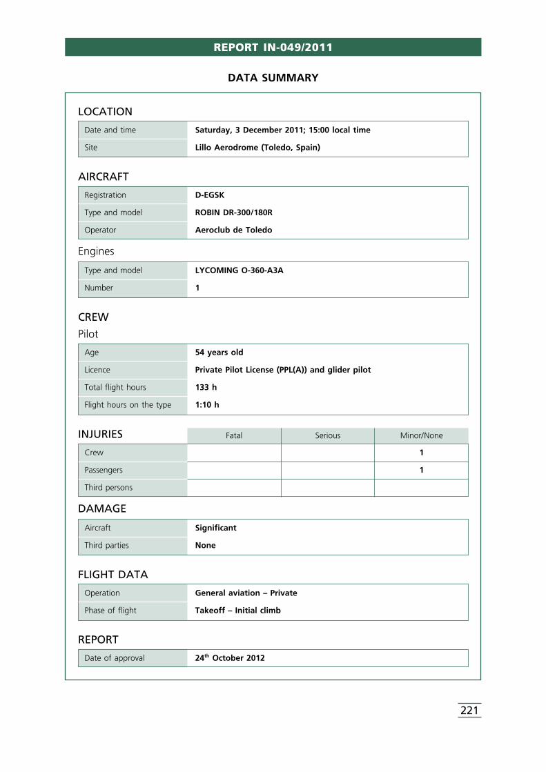
REPORT IN-049/2011
221
LOCATION
Date and time Saturday, 3 December 2011; 15:00 local time
Site Lillo Aerodrome (Toledo, Spain)
FLIGHT DATA
Operation General aviation – Private
Phase of flight Takeoff – Initial climb
REPORT
Date of approval 24th October 2012
CREW
Pilot
Age 54 years old
Licence Private Pilot License (PPL(A)) and glider pilot
Total flight hours 133 h
Flight hours on the type 1:10 h
AIRCRAFT
Registration D-EGSK
Type and model ROBIN DR-300/180R
Operator Aeroclub de Toledo
Engines
Type and model LYCOMING O-360-A3A
Number 1
INJURIES Fatal Serious Minor/None
Crew 1
Passengers 1
Third persons
DAMAGE
Aircraft Significant
Third parties None
DATA SUMMARY
Addenda Bulletin 2/2013
222
1. FACTUAL INFORMATION
1.1. History of the flight
On 3 December 2011, at around 15:00 local time, a Robin DR300/180R aircraft,registration D-EGSK, took off from runway 30 at the Lillo Aerodrome (Toledo) with twooccupants onboard. While on the initial climb, the engine stopped suddenly, forcing thepilot to make an emergency landing on the runway extension. The aircraft’s landinggear, wing and nose section (propeller and mount) were seriously damaged. Neitheroccupant was injured, and both were able to exit the aircraft under their own power.
Prior to using the aircraft to tow gliders, the pilot carried out a preliminary flight for thepurpose of checking the aircraft. Before this flight, the aircraft was refueled with 51 lso as to fill the main 110-l capacity tank. The reserve tank was left empty. The maintank and the fuel filter (gascolator) were then drained and the pre-flight inspection andchecklists specified in the flight manual were completed. During these checks it wasnoted that the magneto RPMs differed by about 125, a situation that was corrected bycleaning the spark plugs.
The taxi phase lasted a few minutes as the aircraft proceeded to the threshold of therunway in use in order to take off. As noted earlier, when the aircraft was at an altitudeof just 100 ft above the ground, the engine stopped suddenly. In light of the altitude,the pilot verified the position of the controls and the instruments and, noting nothingout of the ordinary, made an emergency landing some 300 m past the end of therunway on a crop field that was practically flat.
1.2. Personnel information
The pilot had a valid private pilot license (PPL(A)) with a single-engine piston (land) ratingthat was good until 31/12/2013. The class 2 medical certificate was valid until14/05/2012. He also had linguistic competency and glider pilot certificates, both ofwhich are required for glider towing operations.
1.3. Aircraft information
The Robin DR300/180R aircraft, S/N 653, has two fuel tanks arranged as follows: a 100-l main tank located at the bottom of the center portion of the fuselage, and a 50-lreserve tank located behind the main tank. The two tanks are connected and fuel istransferred by means of gravity.
The aircraft logbook shows that starting on 14 July 2011, the aircraft stopped beingused on a regular basis, with only two flights made after that date before the incidentflight, both lasting 14 minutes and both on 13 November.
The aircraft had been parked in a metal hangar.
Report IN-049/2011
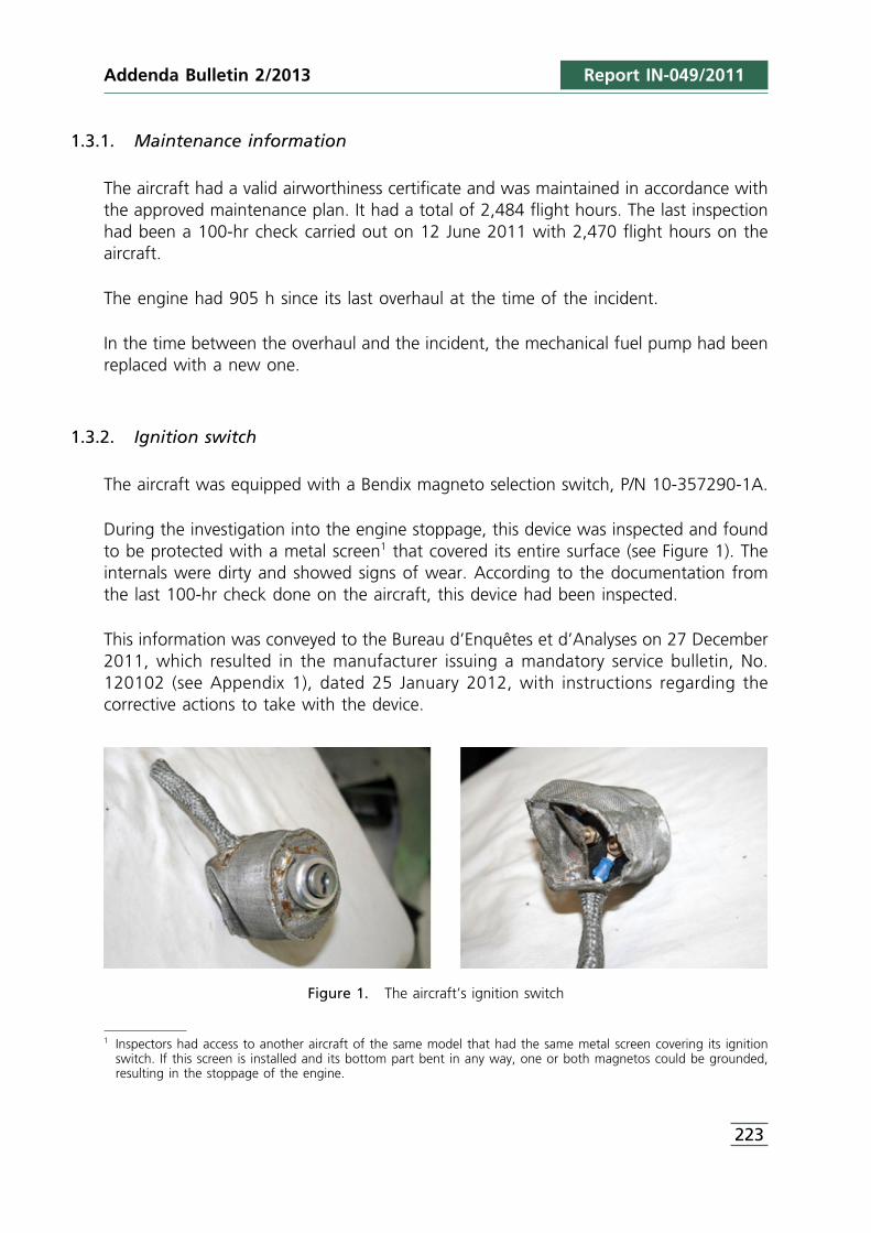
1 Inspectors had access to another aircraft of the same model that had the same metal screen covering its ignitionswitch. If this screen is installed and its bottom part bent in any way, one or both magnetos could be grounded,resulting in the stoppage of the engine.
223
1.3.1. Maintenance information
The aircraft had a valid airworthiness certificate and was maintained in accordance withthe approved maintenance plan. It had a total of 2,484 flight hours. The last inspectionhad been a 100-hr check carried out on 12 June 2011 with 2,470 flight hours on theaircraft.
The engine had 905 h since its last overhaul at the time of the incident.
In the time between the overhaul and the incident, the mechanical fuel pump had beenreplaced with a new one.
1.3.2. Ignition switch
The aircraft was equipped with a Bendix magneto selection switch, P/N 10-357290-1A.
During the investigation into the engine stoppage, this device was inspected and foundto be protected with a metal screen1 that covered its entire surface (see Figure 1). Theinternals were dirty and showed signs of wear. According to the documentation fromthe last 100-hr check done on the aircraft, this device had been inspected.
This information was conveyed to the Bureau d’Enquêtes et d’Analyses on 27 December2011, which resulted in the manufacturer issuing a mandatory service bulletin, No.120102 (see Appendix 1), dated 25 January 2012, with instructions regarding thecorrective actions to take with the device.
Figure 1. The aircraft’s ignition switch
Report IN-049/2011Addenda Bulletin 2/2013
Report IN-049/2011
1.4. Meteorological information
The weather information for the area of the Lillo Aerodrome indicates that thetemperature was around 9 °C and the relative humidity was 69%. Visibility conditionswere good for flying.
1.5. Tests and research
1.5.1. Inspection of the wreckage
An inspection of the aircraft did not reveal any anomalies involving the components oroperation of its fuel, electrical or powerplant systems.
2. ANALYSIS
During the initial climb maneuver, while passing through 100 ft AGL, the aircraft’sengine stopped suddenly and without warning. There was no sign of any malfunctionor loss of power. After doing a quick check of the engine controls and parameters, thepilot decided to land straight in on the field adjacent to the runway.
The inspection and tests conducted on the aircraft after the event did not reveal anysystem malfunction that could account for the engine stoppage. Also considered wasthe incorrect use of the aircraft’s engine controls or auxiliary systems, a possibility thatcould not be ruled out by the checks made by the pilot before and after the enginestoppage.
The possibility that ice formed on the carburetor was also considered in light of theprevailing weather conditions and the time that the engine was in operation prior to takeoff, but at no time did the engine hesitate or show signs or decreasing itsoutput.
Investigators also considered the history of the aircraft in terms of its use and the tasksperformed prior to the incident flight. In this regard, the aircraft had mostly been outof use since 14 July 2011, making only two short flights in the interim. During this time,the aircraft had been kept in a hangar where the weather conditions in the area resultin high temperature fluctuations between day and night. As concerns the tasksperformed prior to the flight, the main tank was half full and was not drained beforeit was refilled, and the reserve tank was empty.
These circumstances would indicate that before the tank was refilled, water hadcondensed in the tank and when the main tank was topped off, the water formed a
224
Addenda Bulletin 2/2013
2 Fuel-water emulsion: an emulsion is a more or less homogeneous mixture of two immiscible liquids, one of whichacts as the dispersed phase (water) and the other as the continuous phase (fuel). Depending on the conditions towhich it is subjected, such as shaking, temperature, the volumes of each liquid, and so on, the phases can reverse.
Addenda Bulletin 2/2013 Report IN-049/2011
partial emulsion with the fuel2. When the mixture was subsequently drained, theemulsion would have been sufficiently homogeneous to hide the presence of water.Then, while the aircraft was on the apron, the emulsion reversed with the water’spresence in the fuel supply becoming evident during takeoff and causing the engine tostop.
3. CONCLUSION
3.1. Findings
• The aircraft had a valid airworthiness certificate issued by the State of registration,and was maintained in accordance with its approved maintenance plan.
• The pilot had a valid flight license and the ratings required for the flight, including alinguistic competency certificate.
• An inspection of the aircraft’s systems did not reveal any signs of a malfunction.• During the inspection it was noted that a metal screen had been installed that
covered the ignition switch. This resulted in the manufacturer’s issuing of amandatory service bulletin to correct this type of installation.
• Conditions were favorable for water to have formed in the fuel tank (time aircraftwas out of service, external temperature changes and partially full fuel tanks).
• The drainage procedure was performed incorrectly since it was carried out after therefueling.
3.2. Causes
The most probable cause of the sudden engine stoppage during the initial climb wasthe intake of water from the main fuel tank by the engine.
225

APPENDIX 1Service bulletin no. 120102
Addenda Bulletin 2/2013 Report IN-049/2011
227
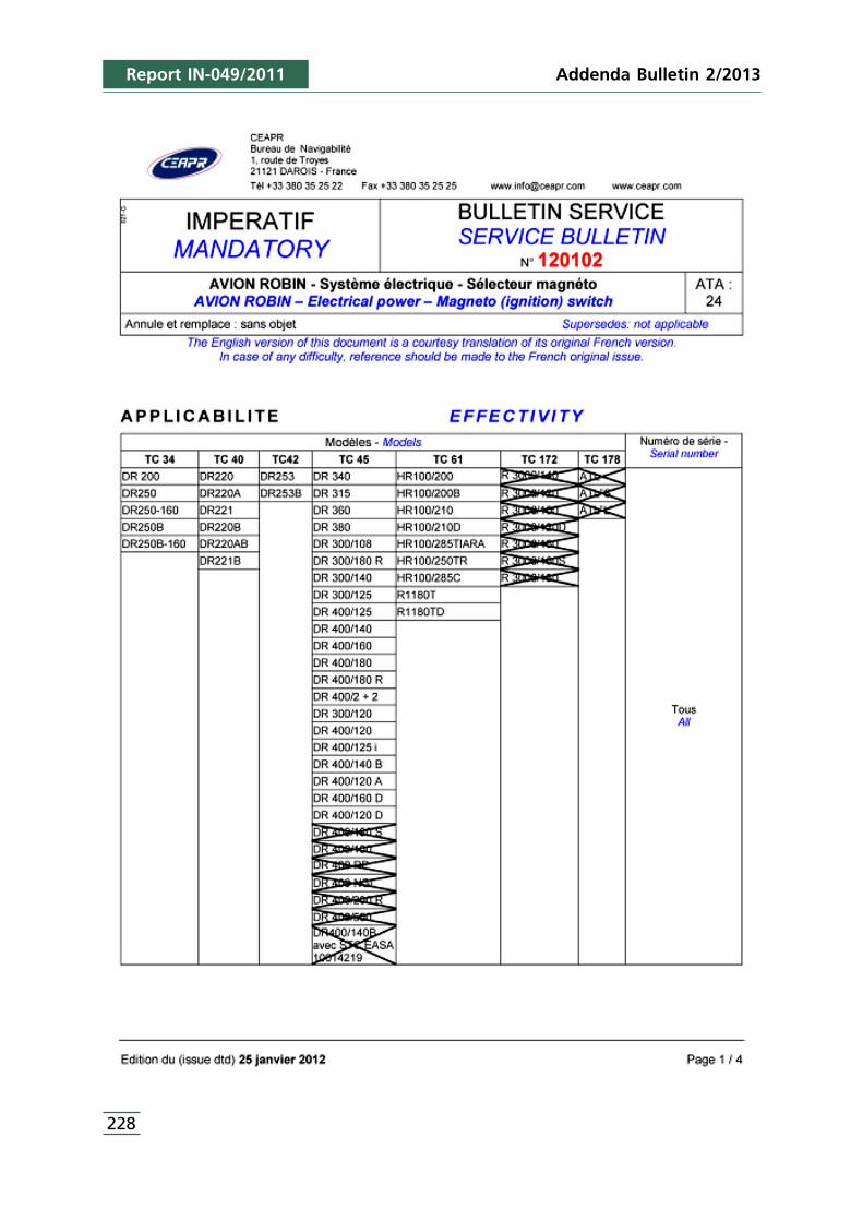
Report IN-049/2011
228
Addenda Bulletin 2/2013
Addenda Bulletin 2/2013 Report IN-049/2011
229
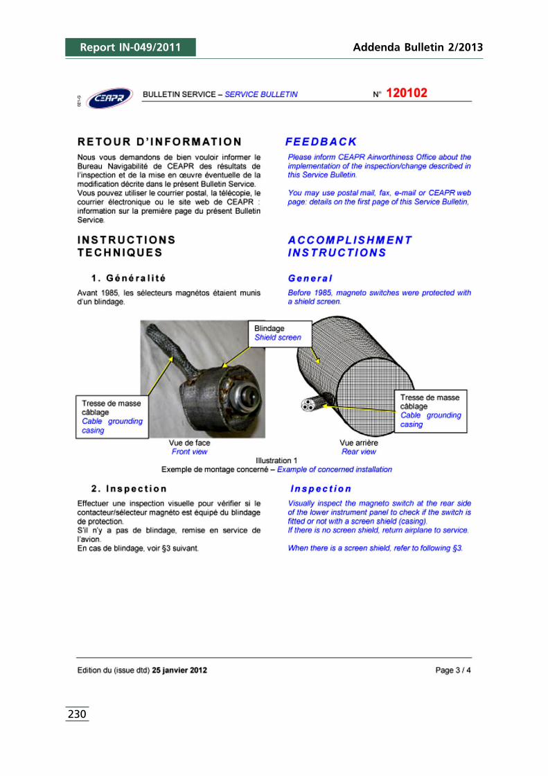
Report IN-049/2011
230
Addenda Bulletin 2/2013
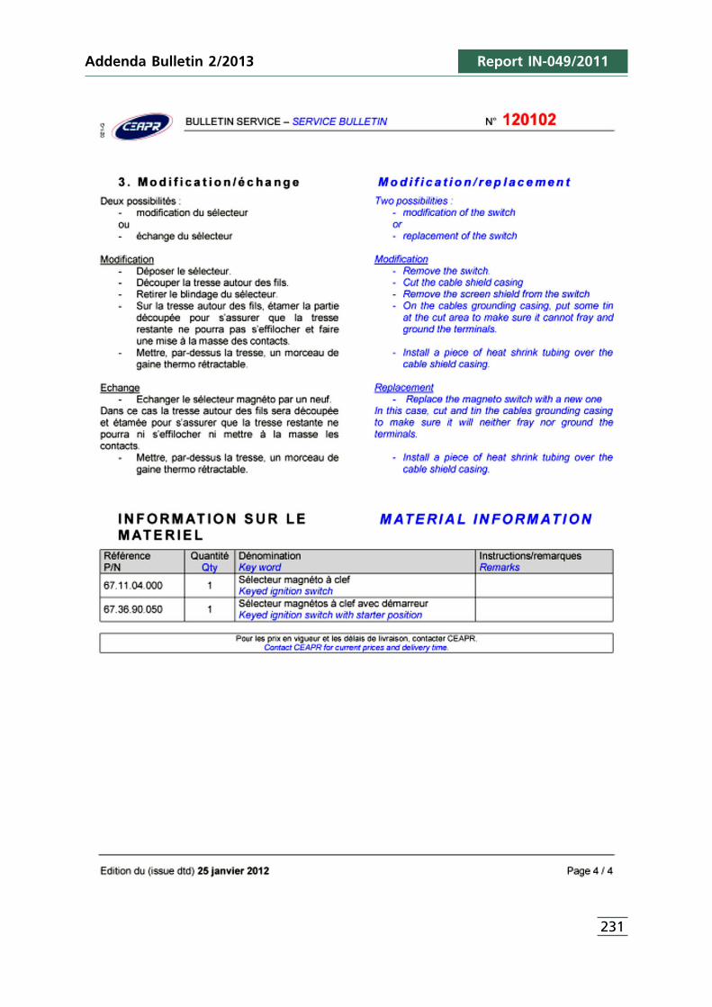
Addenda Bulletin 2/2013 Report IN-049/2011
231

REPORT IN-014/2012
233
1 All times in this report are in UTC unless otherwise specified. To obtain local time, add two hours to UTC time.
LOCATION
Date and time Tuesday, 8 May 2012; 07:45 UTC1
Site Jerez Airport (LEJR) – Jerez de la Frontera (Cádiz, Spain)
FLIGHT DATA
Operation General aviation – Instruction – Solo
Phase of flight Parked – Engine test
REPORT
Date of approval 28 February 2013
CREW
Pilot in command
Age 21 years old
Licence Student Pilot Authorization
Total flight hours 119.1 h
Flight hours on the type 119.1 h
AIRCRAFT
Registration EC-IOT
Type and model PIPER PA-28-161 “Warrior”
Operator Flight Training Europe (FTE) JEREZ
Engines
Type and model LYCOMING O-320-D3G
Number 1
INJURIES Fatal Serious Minor/None
Crew 1
Passengers
Third persons
DAMAGE
Aircraft Minor
Third parties None
DATA SUMMARY
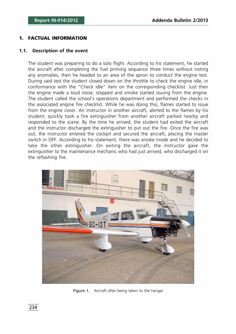
Report IN-014/2012
1. FACTUAL INFORMATION
1.1. Description of the event
The student was preparing to do a solo flight. According to his statement, he startedthe aircraft after completing the fuel priming sequence three times without notingany anomalies, then he headed to an area of the apron to conduct the engine test.During said test the student closed down on the throttle to check the engine idle, inconformance with the “Check idle” item on the corresponding checklist. Just thenthe engine made a loud noise, stopped and smoke started issuing from the engine.The student called the school’s operations department and performed the checks inthe associated engine fire checklist. While he was doing this, flames started to issuefrom the engine cover. An instructor in another aircraft, alerted to the flames by hisstudent, quickly took a fire extinguisher from another aircraft parked nearby andresponded to the scene. By the time he arrived, the student had exited the aircraftand the instructor discharged the extinguisher to put out the fire. Once the fire wasout, the instructor entered the cockpit and secured the aircraft, placing the masterswitch in OFF. According to his statement, there was smoke inside and he decided totake the other extinguisher. On exiting the aircraft, the instructor gave theextinguisher to the maintenance mechanic who had just arrived, who discharged it onthe reflashing fire.
Figure 1. Aircraft after being taken to the hangar
234
Addenda Bulletin 2/2013
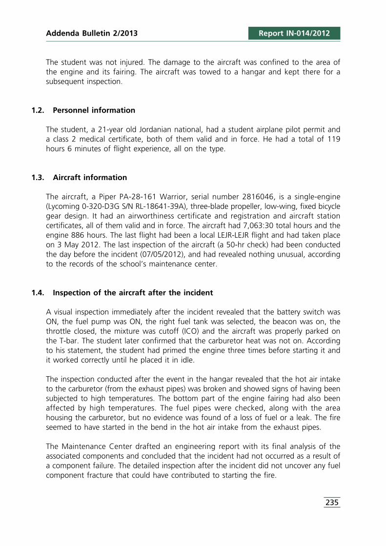
Addenda Bulletin 2/2013 Report IN-014/2012
The student was not injured. The damage to the aircraft was confined to the area ofthe engine and its fairing. The aircraft was towed to a hangar and kept there for asubsequent inspection.
1.2. Personnel information
The student, a 21-year old Jordanian national, had a student airplane pilot permit anda class 2 medical certificate, both of them valid and in force. He had a total of 119hours 6 minutes of flight experience, all on the type.
1.3. Aircraft information
The aircraft, a Piper PA-28-161 Warrior, serial number 2816046, is a single-engine(Lycoming 0-320-D3G S/N RL-18641-39A), three-blade propeller, low-wing, fixed bicyclegear design. It had an airworthiness certificate and registration and aircraft stationcertificates, all of them valid and in force. The aircraft had 7,063:30 total hours and theengine 886 hours. The last flight had been a local LEJR-LEJR flight and had taken placeon 3 May 2012. The last inspection of the aircraft (a 50-hr check) had been conductedthe day before the incident (07/05/2012), and had revealed nothing unusual, accordingto the records of the school’s maintenance center.
1.4. Inspection of the aircraft after the incident
A visual inspection immediately after the incident revealed that the battery switch wasON, the fuel pump was ON, the right fuel tank was selected, the beacon was on, thethrottle closed, the mixture was cutoff (ICO) and the aircraft was properly parked onthe T-bar. The student later confirmed that the carburetor heat was not on. Accordingto his statement, the student had primed the engine three times before starting it andit worked correctly until he placed it in idle.
The inspection conducted after the event in the hangar revealed that the hot air intaketo the carburetor (from the exhaust pipes) was broken and showed signs of having beensubjected to high temperatures. The bottom part of the engine fairing had also beenaffected by high temperatures. The fuel pipes were checked, along with the areahousing the carburetor, but no evidence was found of a loss of fuel or a leak. The fireseemed to have started in the bend in the hot air intake from the exhaust pipes.
The Maintenance Center drafted an engineering report with its final analysis of theassociated components and concluded that the incident had not occurred as a result ofa component failure. The detailed inspection after the incident did not uncover any fuelcomponent fracture that could have contributed to starting the fire.
235
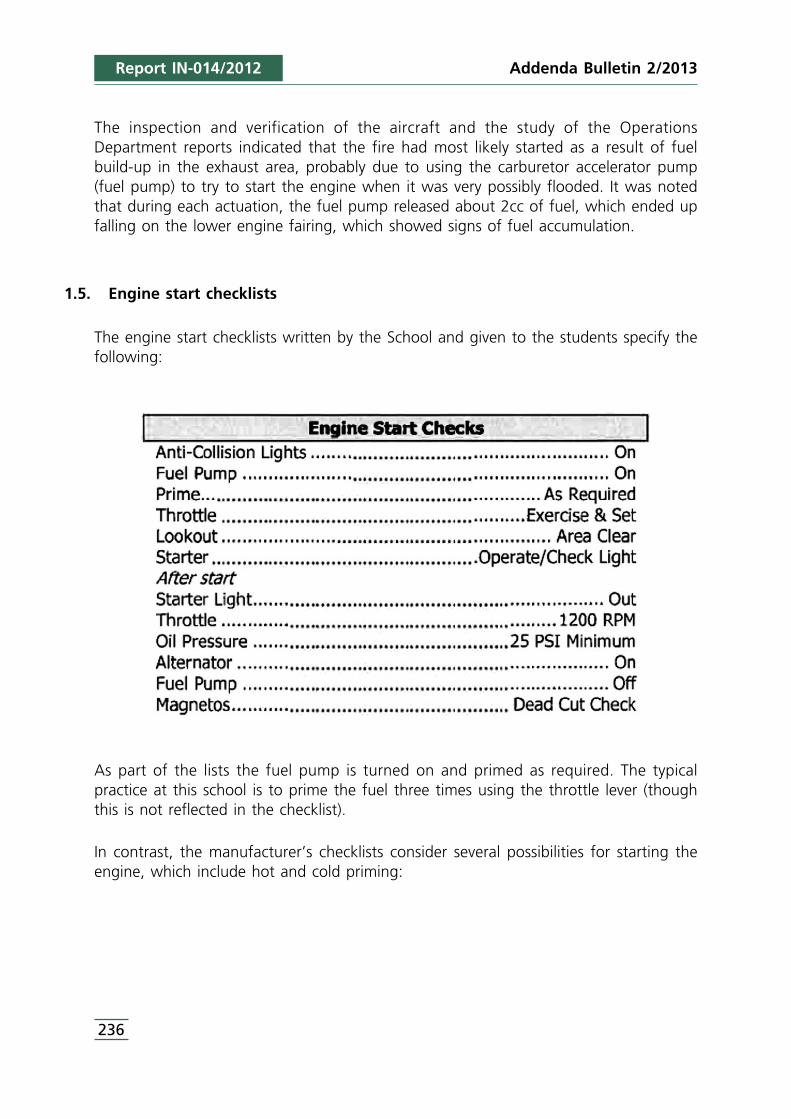
Addenda Bulletin 2/2013
236
The inspection and verification of the aircraft and the study of the OperationsDepartment reports indicated that the fire had most likely started as a result of fuelbuild-up in the exhaust area, probably due to using the carburetor accelerator pump(fuel pump) to try to start the engine when it was very possibly flooded. It was notedthat during each actuation, the fuel pump released about 2cc of fuel, which ended upfalling on the lower engine fairing, which showed signs of fuel accumulation.
1.5. Engine start checklists
The engine start checklists written by the School and given to the students specify thefollowing:
As part of the lists the fuel pump is turned on and primed as required. The typicalpractice at this school is to prime the fuel three times using the throttle lever (thoughthis is not reflected in the checklist).
In contrast, the manufacturer’s checklists consider several possibilities for starting theengine, which include hot and cold priming:
Report IN-014/2012

237
The school was asked about explicitly adding the priming item to its checklists, since themanufacturer made no such reference. The school reported that the aircraft hadpreviously been used at a flight school in Scotland and, after checking with that school’sflight safety office, it was concluded that the checklists had been modified as a resultof the cold temperatures there, which always made it necessary to prime the enginebefore starting it. These lists had not been adapted to reflect the temperatures in Spainafter the airplane was taken to Jerez.
1.6. Aerodrome information
The Jerez Airport is located within the city limits of Jerez de la Frontera, 8 kilometersnortheast of the city proper. Its ARP is at an elevation of 93 ft (28 m).
The airport has one 2,300-m long, 45-m wide asphalt runway in a 02/20 orientation.
The school’s aircraft park at point 1 and engine tests are normally conducted at point2 (see Figure 2).
Report IN-014/2012Addenda Bulletin 2/2013
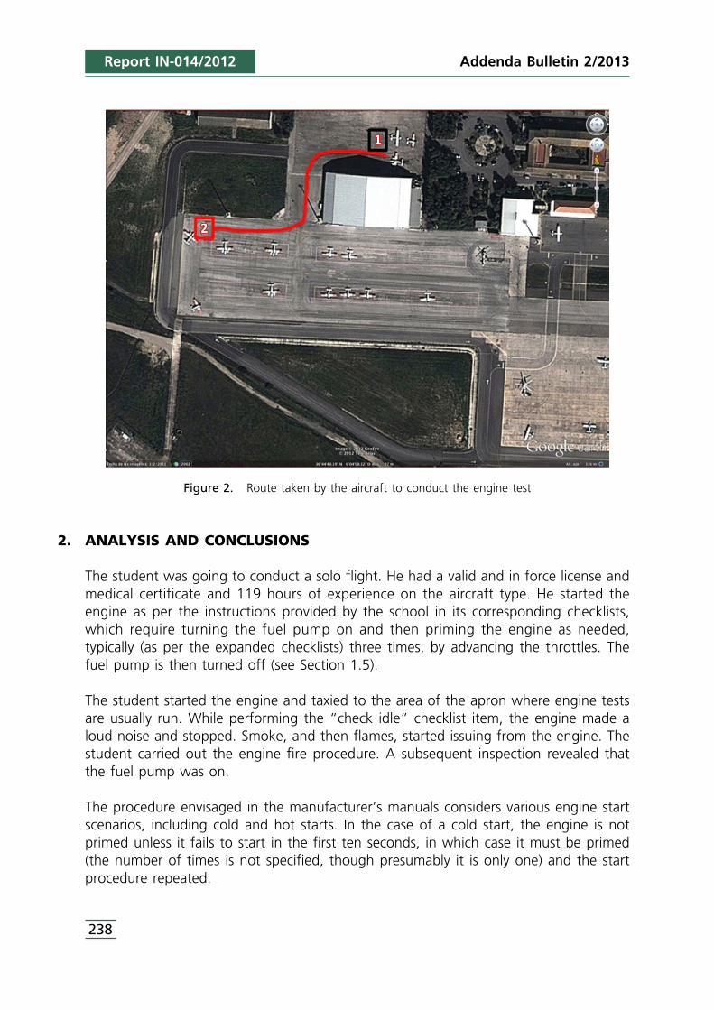
Report IN-014/2012
Figure 2. Route taken by the aircraft to conduct the engine test
2. ANALYSIS AND CONCLUSIONS
The student was going to conduct a solo flight. He had a valid and in force license andmedical certificate and 119 hours of experience on the aircraft type. He started theengine as per the instructions provided by the school in its corresponding checklists,which require turning the fuel pump on and then priming the engine as needed,typically (as per the expanded checklists) three times, by advancing the throttles. Thefuel pump is then turned off (see Section 1.5).
The student started the engine and taxied to the area of the apron where engine testsare usually run. While performing the “check idle” checklist item, the engine made aloud noise and stopped. Smoke, and then flames, started issuing from the engine. Thestudent carried out the engine fire procedure. A subsequent inspection revealed thatthe fuel pump was on.
The procedure envisaged in the manufacturer’s manuals considers various engine startscenarios, including cold and hot starts. In the case of a cold start, the engine is notprimed unless it fails to start in the first ten seconds, in which case it must be primed(the number of times is not specified, though presumably it is only one) and the startprocedure repeated.
238
Addenda Bulletin 2/2013
Addenda Bulletin 2/2013 Report IN-014/2012
Due to the differences between the manufacturer’s checklists and those provided by theschool, the latter was asked about the reason for explicitly adding the primingrequirement in its checklists, something that was missing from the manufacturer’s. Theschool told investigators that the aircraft had previously been used at a flight school inScotland. Further checking revealed that the checklists had been modified as a result ofthe cold temperatures there, which made it impossible to start the engine withoutpriming it first. These lists had not been adapted to reflect the temperatures in Spainafter being taken to Jerez. That is why the school drafted a modification to theexpanded checklists to adapt them once more to the manufacturer’s, though the“Prime: As required” item was kept in the normal checklists, along with a flight crewnotice (see Appendix A) on the conditions in which to perform this step. The schoolcommitted to revising all of the expanded checklists and incorporating them in theOperations Manual.
The incident is considered to have occurred due to excessive priming of the engine andto the possible operation of the fuel pump during the engine test, which resulted in theexcess fuel contacting a hot spot and igniting the fire.
The investigation revealed that the excess priming of the engine before starting was acommon practice among the school’s students, since the checklists required this step. Itwas noted that the manufacturer’s checklists did not by default recommend priming theengine, and that the operator’s checklists had been modified as a result of the aircraft’sprevious operating environment (colder temperatures), modifications that had not beenconsidered when the airplane was transferred to Spain.
No safety considerations are warranted since the operator was in the process ofmodifying the expanded checklists to conform to the manufacturer’s in terms of primingthe engine before start.
239


APPENDIX AFlight Crew Notice
Addenda Bulletin 2/2013 Report IN-014/2012
241
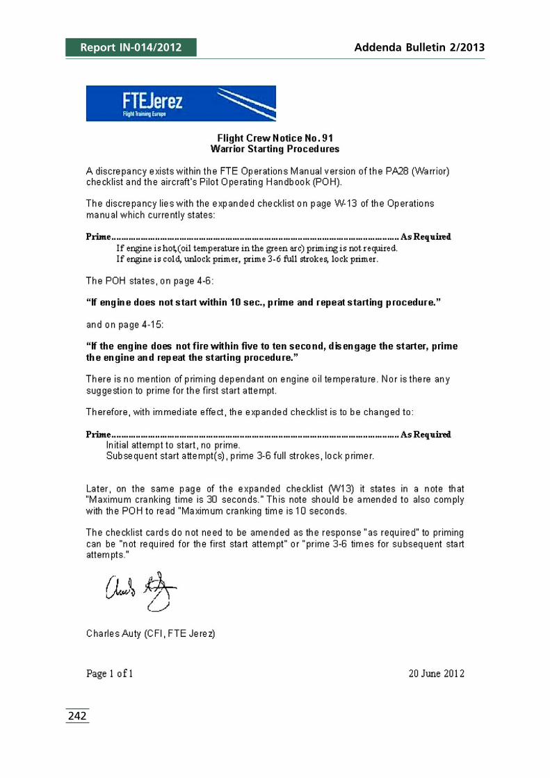
Addenda Bulletin 2/2013
242
Report IN-014/2012
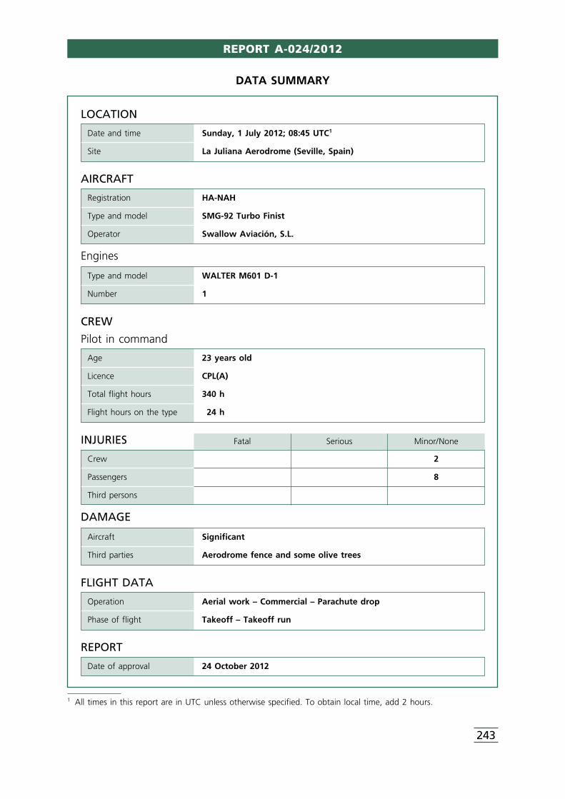
REPORT A-024/2012
243
1 All times in this report are in UTC unless otherwise specified. To obtain local time, add 2 hours.
LOCATION
Date and time Sunday, 1 July 2012; 08:45 UTC1
Site La Juliana Aerodrome (Seville, Spain)
FLIGHT DATA
Operation Aerial work – Commercial – Parachute drop
Phase of flight Takeoff – Takeoff run
REPORT
Date of approval 24 October 2012
CREW
Pilot in command
Age 23 years old
Licence CPL(A)
Total flight hours 340 h
Flight hours on the type 24 h
AIRCRAFT
Registration HA-NAH
Type and model SMG-92 Turbo Finist
Operator Swallow Aviación, S.L.
Engines
Type and model WALTER M601 D-1
Number 1
INJURIES Fatal Serious Minor/None
Crew 2
Passengers 8
Third persons
DAMAGE
Aircraft Significant
Third parties Aerodrome fence and some olive trees
DATA SUMMARY
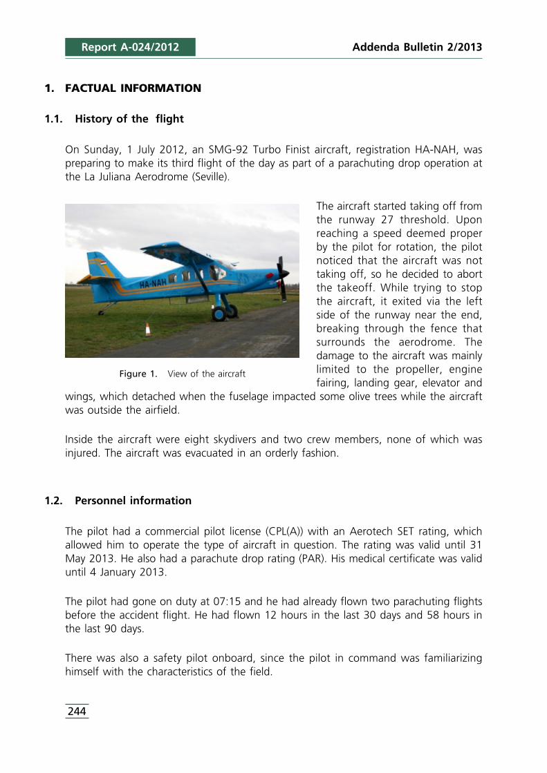
Addenda Bulletin 2/2013
244
1. FACTUAL INFORMATION
1.1. History of the flight
On Sunday, 1 July 2012, an SMG-92 Turbo Finist aircraft, registration HA-NAH, waspreparing to make its third flight of the day as part of a parachuting drop operation atthe La Juliana Aerodrome (Seville).
The aircraft started taking off fromthe runway 27 threshold. Uponreaching a speed deemed properby the pilot for rotation, the pilotnoticed that the aircraft was nottaking off, so he decided to abortthe takeoff. While trying to stopthe aircraft, it exited via the leftside of the runway near the end,breaking through the fence thatsurrounds the aerodrome. Thedamage to the aircraft was mainlylimited to the propeller, enginefairing, landing gear, elevator and
wings, which detached when the fuselage impacted some olive trees while the aircraftwas outside the airfield.
Inside the aircraft were eight skydivers and two crew members, none of which wasinjured. The aircraft was evacuated in an orderly fashion.
1.2. Personnel information
The pilot had a commercial pilot license (CPL(A)) with an Aerotech SET rating, whichallowed him to operate the type of aircraft in question. The rating was valid until 31May 2013. He also had a parachute drop rating (PAR). His medical certificate was validuntil 4 January 2013.
The pilot had gone on duty at 07:15 and he had already flown two parachuting flightsbefore the accident flight. He had flown 12 hours in the last 30 days and 58 hours inthe last 90 days.
There was also a safety pilot onboard, since the pilot in command was familiarizinghimself with the characteristics of the field.
Report A-024/2012
Figure 1. View of the aircraft
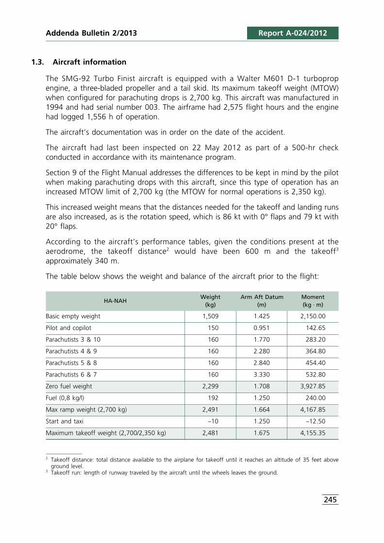
245
1.3. Aircraft information
The SMG-92 Turbo Finist aircraft is equipped with a Walter M601 D-1 turbopropengine, a three-bladed propeller and a tail skid. Its maximum takeoff weight (MTOW)when configured for parachuting drops is 2,700 kg. This aircraft was manufactured in1994 and had serial number 003. The airframe had 2,575 flight hours and the enginehad logged 1,556 h of operation.
The aircraft’s documentation was in order on the date of the accident.
The aircraft had last been inspected on 22 May 2012 as part of a 500-hr checkconducted in accordance with its maintenance program.
Section 9 of the Flight Manual addresses the differences to be kept in mind by the pilotwhen making parachuting drops with this aircraft, since this type of operation has anincreased MTOW limit of 2,700 kg (the MTOW for normal operations is 2,350 kg).
This increased weight means that the distances needed for the takeoff and landing runsare also increased, as is the rotation speed, which is 86 kt with 0° flaps and 79 kt with20° flaps.
According to the aircraft’s performance tables, given the conditions present at theaerodrome, the takeoff distance2 would have been 600 m and the takeoff3
approximately 340 m.
The table below shows the weight and balance of the aircraft prior to the flight:
Weight Arm Aft Datum MomentHA-NAH
(kg) (m) (kg · m)
Basic empty weight 1,509 1.425 2,150.00
Pilot and copilot 150 0.951 142.65
Parachutists 3 & 10 160 1.770 283.20
Parachutists 4 & 9 160 2.280 364.80
Parachutists 5 & 8 160 2.840 454.40
Parachutists 6 & 7 160 3.330 532.80
Zero fuel weight 2,299 1.708 3,927.85
Fuel (0,8 kg/l) 192 1.250 240.00
Max ramp weight (2,700 kg) 2,491 1.664 4,167.85
Start and taxi –10 1.250 –12.50
Maximum takeoff weight (2,700/2,350 kg) 2,481 1.675 4,155.35
Report A-024/2012Addenda Bulletin 2/2013
2 Takeoff distance: total distance available to the airplane for takeoff until it reaches an altitude of 35 feet aboveground level.
3 Takeoff run: length of runway traveled by the aircraft until the wheels leaves the ground.
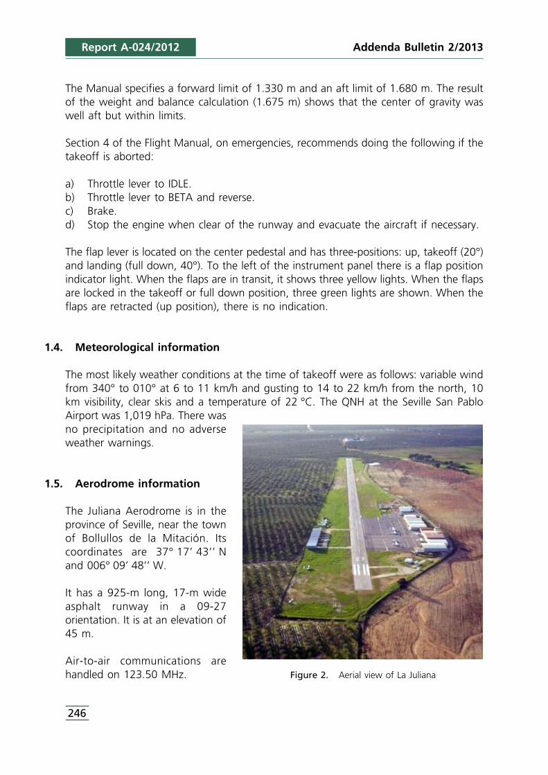
Addenda Bulletin 2/2013
246
The Manual specifies a forward limit of 1.330 m and an aft limit of 1.680 m. The resultof the weight and balance calculation (1.675 m) shows that the center of gravity waswell aft but within limits.
Section 4 of the Flight Manual, on emergencies, recommends doing the following if thetakeoff is aborted:
a) Throttle lever to IDLE.b) Throttle lever to BETA and reverse.c) Brake.d) Stop the engine when clear of the runway and evacuate the aircraft if necessary.
The flap lever is located on the center pedestal and has three-positions: up, takeoff (20°)and landing (full down, 40°). To the left of the instrument panel there is a flap positionindicator light. When the flaps are in transit, it shows three yellow lights. When the flapsare locked in the takeoff or full down position, three green lights are shown. When theflaps are retracted (up position), there is no indication.
1.4. Meteorological information
The most likely weather conditions at the time of takeoff were as follows: variable windfrom 340° to 010° at 6 to 11 km/h and gusting to 14 to 22 km/h from the north, 10km visibility, clear skis and a temperature of 22 °C. The QNH at the Seville San PabloAirport was 1,019 hPa. There wasno precipitation and no adverseweather warnings.
1.5. Aerodrome information
The Juliana Aerodrome is in theprovince of Seville, near the townof Bollullos de la Mitación. Itscoordinates are 37° 17’ 43’’ Nand 006° 09’ 48’’ W.
It has a 925-m long, 17-m wideasphalt runway in a 09-27orientation. It is at an elevation of45 m.
Air-to-air communications arehandled on 123.50 MHz.
Report A-024/2012
Figure 2. Aerial view of La Juliana
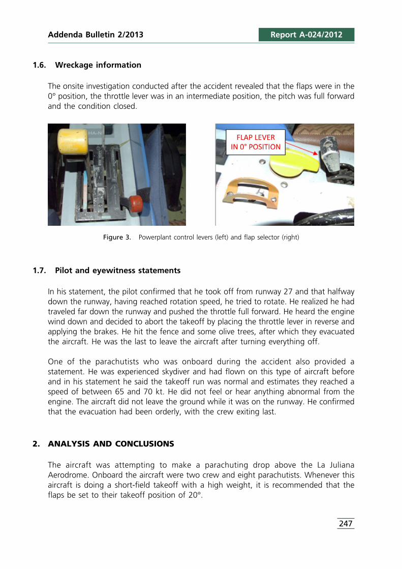
247
1.6. Wreckage information
The onsite investigation conducted after the accident revealed that the flaps were in the0° position, the throttle lever was in an intermediate position, the pitch was full forwardand the condition closed.
Figure 3. Powerplant control levers (left) and flap selector (right)
1.7. Pilot and eyewitness statements
In his statement, the pilot confirmed that he took off from runway 27 and that halfwaydown the runway, having reached rotation speed, he tried to rotate. He realized he hadtraveled far down the runway and pushed the throttle full forward. He heard the enginewind down and decided to abort the takeoff by placing the throttle lever in reverse andapplying the brakes. He hit the fence and some olive trees, after which they evacuatedthe aircraft. He was the last to leave the aircraft after turning everything off.
One of the parachutists who was onboard during the accident also provided astatement. He was experienced skydiver and had flown on this type of aircraft beforeand in his statement he said the takeoff run was normal and estimates they reached aspeed of between 65 and 70 kt. He did not feel or hear anything abnormal from theengine. The aircraft did not leave the ground while it was on the runway. He confirmedthat the evacuation had been orderly, with the crew exiting last.
2. ANALYSIS AND CONCLUSIONS
The aircraft was attempting to make a parachuting drop above the La JulianaAerodrome. Onboard the aircraft were two crew and eight parachutists. Whenever thisaircraft is doing a short-field takeoff with a high weight, it is recommended that theflaps be set to their takeoff position of 20°.
Report A-024/2012Addenda Bulletin 2/2013
Addenda Bulletin 2/2013
248
The evidence indicates that the pilot was attempting to take off on runway 27 andforgot to place the flaps in the takeoff position (20°).
Since the flaps were selected to 0° (Up), the aircraft would have needed a speed inexcess of 86 kt to take off, instead of the 79 kt corresponding to a flap position of 20°.
When the aircraft reached a speed deemed adequate by the pilot for takeoff, the pilotattempted to rotate, but the aircraft remained on the ground, so the pilot decided toabort the takeoff. Since the aircraft was not in its ideal takeoff configuration, its speedwas undoubtedly below that needed to rotate.
According to the performance tables, the aircraft would need to cover 340 metersduring its takeoff run, meaning the length of runway available would have been morethan enough to allow the aircraft to accelerate and stop within the runway.
When the pilot stepped on the brakes, he probably did so asymmetrically, causing theaircraft to exit the runway to the left. The distance traveled by the aircraft beforestopping indicates that the pilot did not place the throttle in reverse properly. If he had,this, along with the brakes, would have allowed him to bring the aircraft to a stop muchsooner.
The accident is regarded as having resulted from the improper configuration of the flapsfor takeoff. This caused the pilot to abort the takeoff when, upon reaching the rotationspeed he deemed suitable for takeoff in the given configuration, the aircraft did nottake off. Moreover, his improper inputs to the brakes and the reverse throttle resultedin the aircraft exiting the aircraft and then impacting the aerodrome fence and someolive trees.
Report A-024/2012