
An Economically Feasible Portable Water Purifying Bottle for the Flood Affected Zones

Journal of Computational and Applied Mechanics, Vol. 10, No. 2, (2015), pp. 209–229
DOI: 10.32973/jcam.2015.013
PORTABLE TENT STRUCTURE DESIGNS FOR FLOODPROTECTION
Robert Nagy and Zsolt GasparDepartment of Structural Mechanics, Faculty of Civil Engineering
Budapest University of Technology and EconomicsMuegyetem rkp. 3, 1111 Budapest, Hungary
[email protected], [email protected]
[Received: July 22, 2015, Accepted: September 30, 2015]
Dedicated to Professor Barna Szabo on the occasion of his eightieth birthday
and to Professor Imre Kozak on the occasion of his eighty-fifth birthday
Abstract. In this paper, we present two simple arrangements of portable tent structuresfor flood protection. In the first, an inflated cylinder lifts the top of the textile as the waterlevel rises, while in the second the textile supporting the water pressure of the tide is hungon a steel framework and is filled with water previously. We give a numerical solution forthe nonlinear system of equations of the compatibility and equilibrium conditions, and alsopresent a complete analytic solution to the boundary value problem of the shape of an inex-tensible, weightless, prismatic textile, similar to the sessile drop problem. After discussingthe mechanical behavior of the structures, different geometries capable of withstanding acertain water height are determined by a software developed for this specific purpose en-abling the design for optimum. Furthermore, the basic rules of thumb are also formulated,aiding the preliminary conceptual design.
Mathematical Subject Classification: 65H05, 65B99Keywords: Portable tent, flood protection, sessile drop, elastica, nonlinear pendulum, ana-lytic solution
1. Introduction
Due to climate change, peak water levels more and more often exceed the heightof the existing artificial embankment dams, causing ever increasing difficulties inflood-prone, inhabited areas near regulated rivers. Since the most common currentemergency measures involve laying sandbags thus requiring considerable manpower,new methods are desired. In the first two chapters we present two possible alterna-tives, being fast and easy not only to transport but to construct as well, while inthe last chapter we summarize the parametric representation of the directrix shape ofa weightless, inextensible, prismatic membrane loaded by static water pressure, andwe also derive the closed form equation of the area between the curve and an arbi-trary vertical line. These formulations involve computationally burdensome elliptic
c©2015 Miskolc University Press

210 R. Nagy, Z. Gaspar
functions and their inverses; therefore, solving directly the governing boundary valueproblem by a numerical algorithm is also a good alternative.
2. First arrangement
The international Inflater project [1], managed by the MFKK Invention and ResearchCenter and funded by the EU 7th Framework Programme, aimed to develop novel,affordable mobile flood defense systems. One of the many possibilities presented thereinvolves a self-erecting textile. As participants, we developed a computer programcapable of determining the static and geometric properties of the structure [2]. Thedetailed description of the algorithm and the analysis of the structural behavior aregiven in this section.
2.1. Geometry. This portable structure, mounted on the vertical crown of the ex-isting embankment dam, solely consists of tensile elements. The first component isan inflated cylinder of radius r with diaphragms dividing its length into several cellsand an additional active monitoring system for over-pressure control. The second isa sheet of impermeable textile skirt attached to a generatrix of the cylinder. Thethird component involves several tie-backs of length l welded to the same generatrixat equal distances along the length of the dam. The latter two are anchored to thefoundation, a common fixed point on the horizontal crown of the embankment dam.A representative equilibrium cross-section is depicted in Fig. 1. We describe the setupin the x-y coordinate system. The main input parameters of the structure geome-try are the BCDA textile section length (lBCDA), the AB tie-back length (lAB), theinflated cylinder radius (r), and the supported water level above crown level (h).
lAB
lCD
h
r
αA
B C
D
EF
O x
y
Figure 1. Cross-section of the 1st arrangement
2.2. Behavior of the structure. Initially the structure lies on the ground and iserected as the floating cylinder filled with air lifts the top of the textile with therising water level, while the tie-back – capable of letting the water through – preventsthe whole structure from collapsing. To avoid leakage, diaphragms and an electronicmonitoring system are applied. The sufficiency of the anchorage at point A, althougha critical issue of the general stability, is not addressed here.

Portable tent structure designs for flood protection 211
2.3. Assumptions.
• The cross-section of the structure shows only negligible alterations in the longi-tudinal direction based on three-dimensional finite element simulation results,therefore it is sufficient to examine only the cross section in planar deformationstate after linearly distributing the concentrated tie-back forces along directrixB.• The over-pressure inside the inflated cylinder is high enough to maintain the
circular cross-section, thus we handle it as a rigid body.• The dimensions lBCDA, lAB, and r are constant, that is, all elements have
tensile stiffness large enough for the loads to cause negligibly small strains.• The weight of the textile, the tie-back, and the cylinder are negligible compared
to the loads they bear.
2.4. Theoretical background. The internal forces and the equilibrium geometry ofthe arrangement are determined by a system of four nonlinear transcendental equa-tions. The first two express the equilibrium of the cylinder, while the other two statethe geometric compatibility of the textile.
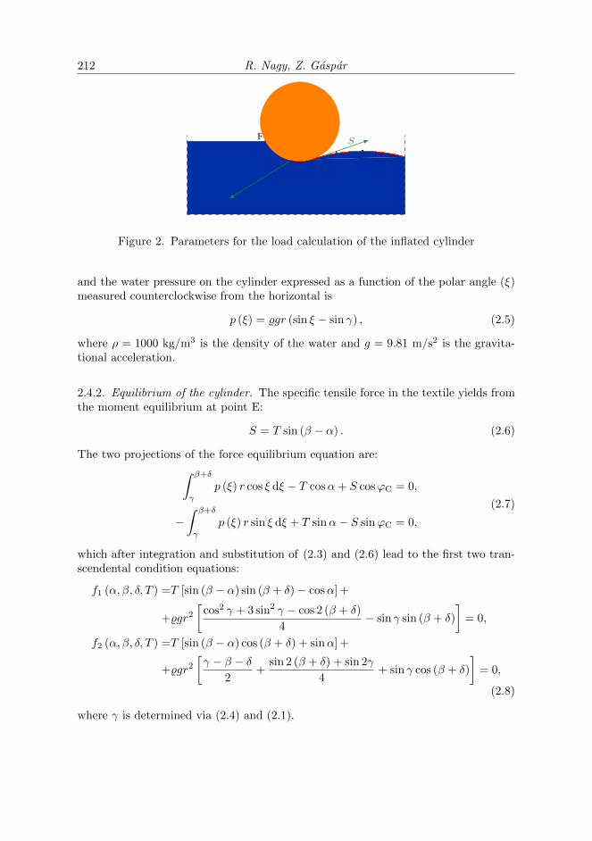
2.4.1. Loads on the cylinder. Fig. 2 shows the loads acting on the inflated cylinder.These are:
1. T , the specific tensile force from the tie-back,2. S, the specific force from the textile tangential to the cylinder, and3. p (ξ) the pressure from the water normal to the cylinder.
We describe the conformation of the whole arrangement by four parameters:
1. α, the inclination of the tie-back from the horizontal,2. β, the angle between the horizontal and the BE line connecting the end of the
tie-back and the center of the cylinder,3. δ, the angle between the BE line and the CE line connecting the point where
the textile separates from the cylinder and the center point, and4. T , the specific force in the tie-back.
In terms of these parameters the coordinates of the center of the cylinder (E) are
xE = lAB cosα+ r cosβ, yE = h− lAB sinα− r sinβ, (2.1)
the coordinates of the point where the canvas separates from the cylinder (C) are
xC = xE − r cos (β + δ) , yC = yE + r sin (β + δ) , (2.2)
the inclination of the tangent of the textile from the horizontal at point C is
ϕC =π
2− β − δ, (2.3)
the inclination of the FE line connecting the point where the water level intersectsthe cylinder and the center of the cylinder from the horizontal is
γ = −arcsinyEr, (2.4)
212 R. Nagy, Z. Gaspar
α
γ
−ϕC
βδ
B C
E
F
T
p (ξ)T
S
Figure 2. Parameters for the load calculation of the inflated cylinder
and the water pressure on the cylinder expressed as a function of the polar angle (ξ)measured counterclockwise from the horizontal is
p (ξ) = %gr (sin ξ − sin γ) , (2.5)
where ρ = 1000 kg/m3 is the density of the water and g = 9.81 m/s2 is the gravita-tional acceleration.
2.4.2. Equilibrium of the cylinder. The specific tensile force in the textile yields fromthe moment equilibrium at point E:
S = T sin (β − α) . (2.6)
The two projections of the force equilibrium equation are:∫ β+δ
γ
p (ξ) r cos ξ dξ − T cosα+ S cosϕC = 0,
−∫ β+δ
γ
p (ξ) r sin ξ dξ + T sinα− S sinϕC = 0,
(2.7)
which after integration and substitution of (2.3) and (2.6) lead to the first two tran-scendental condition equations:
f1 (α, β, δ, T ) =T [sin (β − α) sin (β + δ)− cosα] +
+%gr2[
cos2 γ + 3 sin2 γ − cos 2 (β + δ)
4− sin γ sin (β + δ)
]= 0,
f2 (α, β, δ, T ) =T [sin (β − α) cos (β + δ) + sinα] +
+%gr2[γ − β − δ
2+
sin 2 (β + δ) + sin 2γ
4+ sin γ cos (β + δ)
]= 0,
(2.8)
where γ is determined via (2.4) and (2.1).

Portable tent structure designs for flood protection 213
2.4.3. Geometric compatibility of the textile. The remaining two condition equations:
f3 (α, β, δ, T ) = lBCDA − δ · r–lCD − xD = 0,
f4 (α, β, δ, T ) = h− yD = 0,(2.9)
where lCD, xD, and yD are calculated through (4.15), (4.20), and (4.9)2, respectively,stem from the compatibility conditions of the textile, whose loaded shape determina-tion is described in Section 4.
2.4.4. The nonlinear system of equations. To summarize (2.8) and (2.9), we write:
f (x) = 0, where f =
f1f2f3f4
, and x =
αβδT
. (2.10)
We solve (2.10) by a target code applying the Jacobi method implemented in MAT-LAB 2011a (The MathWorks Inc., Natick, Massachusetts, United States). As statedin (4.7), to find a physically admissible solution that prevents the textile from risingabove water level, that is, to prevent inflection in the directrix, the domain of f isrestricted so that the Eotvos number exceeds the critical value of 1.
2.5. Analysis of the structure.
2.5.1. Water level elevation. As an illustration, the equilibrium geometries of thearrangement lAB = 1.1 m, lBCDA = 3.1 m, r = 0.2 m are shown in the frames ofFig. 3 for water level rising by 10 centimeters. The corresponding specific tensileforce increases in the tie-back (T ) and in the textile (S), along with the tie-backinclination (α), are shown in Fig. 4.
2.5.2. Maximal supported water level. The maximal supported water level h is afunction of lAB, lBCDA, and r together describing the geometry of a given arrange-ment. This extremal state is defined by γ = −π/2. We first consider the value ofr as given and instead of δ we choose ϕC as the independent variable, constrainingyC = r (1 + cosϕC). To reach the desired h = yD, which due to (4.7)1 and (4.9)2 issmaller than
hmax =
√2r2 (1 + cosϕC)
2
1− cosϕC, (2.11)
S is found from (4.9)2 to be
S =ρg(h2 − y2C
)2 (1 + cosϕC)
. (2.12)
ϕC uniquely describes Fx and Fy, the components of the water pressure resultant asshown in Fig. 5 and in (2.13):
Fx =%gr2
2(1 + cosϕC)
2, Fy =
%gr2
2[ϕC − π + sinϕC (2 + cosϕC)] . (2.13)
Through the equilibrium of the cylinder, the tie-back position is determined via

214 R. Nagy, Z. Gaspar
lAB
0.8m
αA
B C
D
EF
Ox
y
lAB
0.9m
αA
B C
D
EF
Ox
y
lAB
1.0m
αA
B C
D
E
F
Ox
y
0.5m
αA
B C
D
E
F
Ox
y lAB0.6m
αA
B C
D
EF
Ox
y lAB
0.7m
αA
B C
D
EF
Ox
y
0.2mα
A
B CD
E
F
Ox
y
0.3m
αA
B C
D
E
F
Ox
y0.4m
αA
B C
D
E
F
Ox
y
Figure 3. Frames of the equilibrium geomery of the arrangementlAB = 1.1 m, lBCDA = 3.1 m, r = 0.2 m in case of the water levelrising by 10 cm in each step.
0 0.2 0.4 0.6 0.8 1
00.5
11.5
22.5
3
h [m]
spec
ific
forc
e[k
N/m
]
T
S
0 0.2 0.4 0.6 0.8 1
010
20
30
h [m]
α[◦]
Figure 4. Specific tensile forces in the tie-back (T ) and in the textile(S) (left), and the tie-back inclination (α) as a function of the risingwater level (h)
α = arctan−S sinϕC − FyS cosϕC + Fx
, β = α+ arcsinFy cosα+ Fx sinα
Fy cosϕC − Fx sinϕC, (2.14)

Portable tent structure designs for flood protection 215
−ϕC
E
F
C
F
= E
F
C
Fx
Fy
−ϕC
Figure 5. Decomposition of the water pressure resultant exerted onthe cylinder in case of the highest possible supported water level
yielding the tie-back and textile lengths:
lAB =h− r (1 + sinβ)
sinα, lBCDA = δ · r + lCD + xD, (2.15)
where δ, lCD and xD are calculated via (2.3), (4.15) and (4.20), respectively.
2.6. Preliminary design.
We have now the possible geometric parameters characterizing the extremal designstate of the structure. For a given r, their relation describes a surface in the three-dimensional (lAB, lBCDA, h) space, the contours of which are shown in Fig. 6 by bluelines, where it becomes possible to optimize the cost of the arrangement. Usually thetextile length is to be minimized, both for financial reasons, and because the top ofthe existing dam it is going to be placed on offers a limited space, consequently theoptimal designs are extremal points of the level lines forming the red curve also shownin Fig. 6. Agreeing upon this condition, we present the design method to define ageometry which is capable of withstanding a water height h:
1. We assume that h includes the uncertainty of the water level and the sur-face wave amplitudes as well. Hence reducing the problem to a quasi-staticinvestigation.
2. As Fig. 7 shows, the tie-back and textile lengths decrease radically with the in-creasing cylinder radius, the critical design parameter, chosen to be the highestfeasible value.
3. lAB and lBCDA are concluded form Fig. 7.4. S and T , the specific textile and tie-back forces are found from Fig. 8.5. For designing the anchorage foundation, the tie-back inclination angle is shown
in Fig. 9.

216 R. Nagy, Z. Gaspar
0 2 4 6 80
2
4
6
8
10
0.2
0.3
0.4
0.5
0.6
0.7
0.8
r = 5 cm
lAB [m]
l BCDA
[m]
Figure 6. Blue level lines of the maximal supported water level, h[m] for a given cylinder radius (r = 5 cm); red curve is the optimalchoice of the geometric parameters.
0 0.2 0.4 0.6 0.8 10
1
2
3
4
5
r [cm]
15
20
57.5
10
h [m]
l AB
[m]
0 0.2 0.4 0.6 0.8 10
1
2
3
4
5
r [cm]
5
7.5
1012.5
1517.5
20
h [m]
l BCDA
[m]
Figure 7. Tie-back and textile lengths as functions of the cylinderradius and maximal supported water level
0 0.2 0.4 0.6 0.8 1
00.5
11.5
22.5
r [cm]
5
20
h [m]
S[kN/m]
0 0.2 0.4 0.6 0.8 1
00.5
11.5
22.5
r [cm]
5
20
h [m]
T[kN/m]
Figure 8. Specific textile and tie-back forces as functions of the cylin-der radius and maximal supported water level

Portable tent structure designs for flood protection 217
0 0.2 0.4 0.6 0.8 10
10
20
30
40
r [cm]
5
7.5
10
12.5
15
17.5
20
h [m]
α[◦]
Figure 9. Extremal tie-back inclination angle as functions of thecylinder radius and maximal supported water level
3. Second arrangement
The second scenario is invoked to life by the Airdome-Mobildam Kft. who approachedus to analyze the structure presented in this chapter. Similarly to the first problem,we give here the shape and the specific forces of the textile and the reaction forces onthe supports.
3.1. Geometry. This arrangement, also mounted on the crown, consists of an im-permeable textile channel attached to a steel framework. A representative loadedcross-section solely of the textile in the plane of a frame position is presented inFig. 10. The textile of cross-sectional length L is suspended on the framework atheight H along two fixed directors, B1 and B2 at a vertical distance d from eachother. The inner water height is hi, the supported tidal water height over the crownis hs.
3.2. Behavior of the structure. Initially the unloaded textile is hanging on thesupporting framework at points B1 and B2. During the fill-up, water is pumpedinside the textile from the rising tide of the river, gradually erecting the yet symmet-ric structure. The rising supported water level deforms the structure violating thesymmetry. At this stage, the weight of the water infill acts as a gravity retaining wall.

218 R. Nagy, Z. Gaspar
d
ths
hiH
ϕ1ϕ2
B1
C1
D1OE
D2
C2
B2
x1
y1
x2
y2
P
φ
Figure 10. Cross-section of the 2nd arrangement
3.3. Assumptions.
• The fixed suspension points (B1 and B2) are connected in the axial directionwith sufficiently stiff elements for the textile to have translational symmetryin that direction. This way the textile is in a planar deformation state.• The weight of the textile is negligible compared to the perpendicular water
pressure it bears, which itself is considered as a static loading. Consequently,the specific tensile forces S1 in the B1C1D1 and S2 in the B2C2ED2 textilesections are constant but not necessarily equal.• All the elements have tensile stiffnesses large enough for the loads to cause
negligibly small strains.
3.4. Unloaded, erected textile shape. Without the tidal water load the erectedstructure is symmetric, therefore we only present the right half (B1C1D1) of thearrangement H = 1.6 m, d = 5 cm and L = 6 m in Fig. 11 with internal waterlevel rising by 20 centimeters. The whole textile is smooth, stretches straight insegment B1C1, leans against the ground in D1O and takes the loaded shape definedin Chapter 4 in segment C1D1. Note, that the horizontal dimension of the structureremains virtually unaltered during the process, thus the approximate formula for thepreliminary design to calculate the horizontal space occupied is:
ta =L2 − 4H2 − d2
2 (L− d). (3.1)
3.4.1. Governing equation. The textile shape results from Chapter 4, while the geo-metric compatibility of the structure as a whole for a given hi internal water level isfulfilled by adjusting S1 in
f1 (S1) = 2
(H − hisinϕ1
+ lC1D1+ xD1
)− L = 0, (3.2)

Portable tent structure designs for flood protection 219
B1
O
Figure 11. Unloaded, erected textile shape during the fillup processwith internal water level rising by 20 centimeters
where lC1D1 and xD1 are found from (4.15) and (4.20), respectively. Based on therestriction on the Hamiltonian of the system (H0 < 0 see Section 4.2), or – in amechanically more expressive form – the horizontal equilibrium of a textile section,the viable values of S1 are taken from (S1,min,∞), where
S1,min =%gh2i
4. (3.3)
We obtain the solution of (3.2) by the bisection method, consequently this unboundedinterval is transformed to the bounded interval of s1 ∈ (0, 1] by introducing
s1 =S1,min
S1. (3.4)
3.4.2. Design parameters. For calculating the necessary strength and stability of theframe the support force components are to be determined. In case of our example weillustrate them in Fig. 12 in terms of the internal water level elevation.

220 R. Nagy, Z. Gaspar
0 0.4 0.8 1.2 1.6
02
46
8
hi [m]
spec
ific
forc
e[k
N/m
]
S
Sx
Sy
0 0.4 0.8 1.2 1.6
20
30
40
50
60
hi [m]ϕ1[◦]
Figure 12. Specific tensile forces and its components in the textile(left), and initial inclination of the textile (right) as functions of therising internal water level
3.5. Loaded geometry. The textile still remains smooth, stretches straight in seg-ment B2C2, leans against the ground in ED1, takes the loaded shape defined inChapter 4 in segment C2D2, and forms a circle section in D2E, the radius (R) andcentral angle (φ) of which is:
R =S2
%g (hi − hs),
φ = arccosR− hsR
.
(3.5)
3.5.1. Governing equation. The geometric compatibility for a given hi and hs is againmet by adjusting S2 in the cross-sectional length error:
f2 (S1) = 2
(H − hisinϕ2
+ lC2D2+Rφ+ xD2
−R sinφ
)− L = 0, (3.6)
where lC2D2 and xD2 are found by evaluating at ϕ = π − φ the functions (4.13) and(4.19), respectively. Similarly to the unloaded case, the solution is obtained by thebisection method, thus the unbounded interval of S2 ∈ (S2,min,∞), where
S2,min =%g(h2i − h2s
)4
(3.7)
is transformed to the bounded interval of s2 ∈ (0, 1] by introducing
s2 =S2,min
S2. (3.8)

Portable tent structure designs for flood protection 221
3.6. Rise of the supported water level. Once the desired internal water levelis reached, its volume (found from (4.21) and shown in Fig. 13) does not changethroughout the increasing loading of the tide. Numerically, after the two internal
0 0.4 0.8 1.2 1.6
00.5
11.5
22.5
3
hi [m]
V[m
3/m]
Figure 13. Specific volume of the infill against its rising level
iteration of S1 and S2 for the geometric compatibility of the two sides, an outerbisection iteration adjusts hi to match the volume requirement:
f3 (hi) = 2V (ϕC, π, S)− V (ϕC1 , π, S1) + V (ϕC2 , ϕD2 , S2) +
+R2φ
2− R2 sin 2φ
4+R (1− cosφ) (xD2 −R sinφ) = 0,
(3.9)
where V is defined in (4.21), arguments with indice 1 and 2 represent the free andthe loaded side, respectively while the symmetric unloaded geometry is referred to bysubscripts without any index. Fixing the infill volume at the value when hi = 1.3 min the unloaded state, the increasing hs deforms the cross-section shown in the framesof Fig. 14. Fig. 15 depicts the tension (S2) in the loaded textile decreasing with hs.
3.7. Conclusions.
• The structure acts as a gravity retaining wall.• The symmetry of the erected structure is violated by the supported tidal water
pressure.• Counter-intuitively, instead of pushing the structure away from the riverbed,
the external water pulls it closer due to the uplift.• The internal water level decreases, although insignificantly (by 5 cm in the
presented example, see Figure 15, where the specific tensile force becomes zeroat hs = 1.25 cm).

222 R. Nagy, Z. Gaspar
B1
C1
D1
O
B2
C2
D2
E
F hi
x1x2
y
0.8m
B1
C1
D1
O
B2
C2
D2
E
F hi
x1x2
y
1.0m
B1
C1
D1
O
B2
C2
D2
E
Fhi
x1x2
y
1.2m
B1
C1
D1
O
B2
C2
D2
E
F
hi
x1x2
y
0.2m
B1
C1
D1
O
B2
C2
D2
E
Fhi
x1x2
y
0.4m
B1
C1
D1
O
B2
C2
D2
E
Fhi
x1x2
y
0.6m
Figure 14. Frames of the structure deformation as the supportedwater level rises by 20 centimeters
0 0.2 0.4 0.6 0.8 1 1.2 1.4
01
23
45
67
89
hs [m]
spec
ific
forc
e[k
N/m
]
S2
S2x
S2y
Figure 15. Specific tensile force and its components in the textileloaded by the rising supported water level
• The textile tension in the supporting side decreases to zero as hs reaches hi,when the supporting textile loosens and its shape becomes undefined.• The properties of the side away from the river depend only on the internal
water level, which is virtually unaltered, thus its shape and tension agreeswith the unloaded state.

Portable tent structure designs for flood protection 223
• hs = hi is the critical state from stability point of view, when total load ofthe tide acts only on the outer textile part, while the balancing tension in theother side of the textile is missing.
3.8. Preliminary design. The preliminary design for an expected hs,max starts withprescribing H and d for the framework and t, the necessary minimal length wherethe textile touches the ground at the time of the maximal tidal level to prevent theriver flooding out and to provide the overall stability of the structure; and results inthe critical design force descriptors from the point of view of the framework: S1, thespecific force in the outer textile part and ϕC1
, the inclination of the textile tangentat point C1. In Figure 16, we present the design charts supporting this simplifiedwork-flow. We consider the limit case when hi = 1.25hs,max, and assume that H = hi.Having been agreed upon the safety ratio of 1.25 and infill ratio of 1, the designerchooses a suitable t, adjusts it by d and from the left graph on Figure 16 the necessarycross-sectional textile length is obtained alongside with S1 as is ϕC1
from the charton the right. For a given H, the increase in L causes a decrease in both S1 and ϕC1
,thus not only because of the limited space available and cost efficiency reasons, butbecause of overall structural stability issues, the shortest L is to be chosen meetingthe criterion on t.
2 4 6 8 10
01
23
45
6
0.8
1.0
1.2
1.4
1.6
H [m]
0.2 0.4
0.6
0.8
1.0
t− d [m]
L [m]
spec
ific
forc
e[k
N/m
]
2 4 6 8 10
010
20
30
40
50
0.8
1.0
1.2
1.4
1.6
H [m]
L [m]
ϕC
[◦]
Figure 16. Dependence of the specific force in the outer textile part(S1) (left) and the inclination of the textile tangent from the verticalat point C1 (ϕC1
) (right) on the cross-sectional textile length (L) andthe framework height (H) when the supported water height (hs) is0.8H

224 R. Nagy, Z. Gaspar
4. Shape of the loaded textile section
Consider a prismatic, weightless, inextensible textile supporting static water pressure,the cross-section of which is shown in Fig. 17, where the water level is at y = 0. In thissection we give the parametric functional description of this directrix (in the followingreferred to as fiber) shape and the closed form equation of the V area between thecurve and the y axis. For similar structures, such as closed pressurized geomembranetubes c.f. [3] for the elastic case, [4] for stacked arrangement, [5] for infill with liquidsof different density, [6] for compressible subgrade soil; or [7] for liquid filled nonlinearlyelastic shells.
V
lCD
ϕCC
D
OxC
yC
yD
xDx
y
Figure 17. Boundary value problem of the textile shape loaded bystatic water pressure
4.1. Initial value problem. The initial value problem of ordinary differential equa-tions describing the fiber shape is given by
x′ = cosϕ,
y′ = sinϕ,
ϕ′ =%g
Sy,
x (0) = xC ,
y (0) = yC ,
ϕ (0) = ϕC ,
(4.1)
where x and y are the horizontal and vertical coordinates respectively, ϕ is the incli-nation of the tangent from the positive x axis in clockwise direction. % is the waterdensity, g is the gravitational acceleration, S is the specific tensile force in the fiber,and prime denotes the derivative with respect to the arch length parameter (λ). Thefirst two equations are the compatibility conditions and the third is the tangentialequilibrium statement. Since the fiber weight is negligible and the water pressure isnormal to the curve, the equilibrium condition in the normal direction prescribes thespecific tension (S) in the fiber being constant. By eliminating y from the last two

Portable tent structure designs for flood protection 225
ODEs of (4.1), we simplify the problem to
ϕ′′ = ω2 sinϕ, ϕ′ (0) = ω2yC , ϕ (0) = yC , ω2 =%g
S, (4.2)
which is analogous to the nonlinear pendulum equation [8] except the sign change.The same equation governs the elastica [9] and capillarity problems and if we considerS to be the surface tension, we arrive at the problem of sessile drops.
4.2. The first integral. We can define the corresponding Lagrangian:
L = ϕ′2 + 4ω2 sin2 ϕ
2, (4.3)
which does not depend explicitly on the arch-length, thus following Noether’s theo-rem [10] we construct a conserved quantity:
H = ϕ′2 − 4ω2 sin2 ϕ
2= const. (4.4)
This – speaking in mechanical terms – states the horizontal equilibrium of a textilesection. At a certain depth the first term is proportional to the horizontal hydrostaticload resultant, the second is proportional to the horizontal tensile force in the textile,resulting in the alternate form of (4.4):
H =ρgy2
2+ S cosϕ = const. (4.5)
In the followings we work with the form of (4.4). This translational symmetry, analo-gous to the energy or the Hamiltonian of the pendulum moving in conservative field,suggests scrutinizing the periodic phase space and its two qualitatively different tra-jectories DTCD (0 < H = const.) and SUVS (0 > H = const.) separated by thedash-dotted separatrix (H = 0) in Fig. 18. We introduce two constants:
H0 = ω4y2C −Hp sin2 ϕC2, Hp = 4ω2, (4.6)
which correspond to the total energy and the maximal potential energy of the pen-dulum, respectively.
In case of the first arrangement (Chapter 2), we allow only the curves above theupper separatrix since it restricts the y coordinate to be positive, that is the fibredoes not rise above the water level, and has no inflection, which is the only physicallyacceptable scenario, analogous to the overturning pendulum. The necessary criterionis H0 > 0, which yields an inequality constraint to the boundary conditions given by
yC > yl, where yl =
√2 (1− cosϕc)S
%g, or
Eo > 1, where Eo =%gy2c
2 (1− cosϕc)S.
(4.7)
Here yl is the capillarity length and Eo is the Eotvos number both measuring therelationship between the gravity and surface tension effects, and are extensively used

226 R. Nagy, Z. Gaspar
PQ Q−π π
T
DD
SR
UU
VV
C
H0 > 0
H0 < 0
H0 = 0
ϕ
ϕ′
ϕC
ω2yC
ω2yD
Figure 18. Phase space of the Hamiltonian
for analyzing capillarity phenomena such as the shape of pendant or sessile drops [11].Now we are able to determine
y (ϕ) =
√y2C +
4
ω2
(sin2 ϕ
2− sin2 ϕC
2
), (4.8)
which gives us the maximal and minimal textile heights denoted by points D and Tin the phase space:
yT =
√y2C −
2
ω2(1− cosϕC),
yD =
√y2C +
2
ω2(1 + cosϕC).
(4.9)
In case of the second arrangement (Chapter 3), analogous to the oscillating pendulum,the only viable curves are between the separatrices (H0 < 0) with initial conditionsϕ′ = 0 and ϕ > 0, turning around the relations in (4.7), but leaving (4.8) unaltered.
4.3. Elliptic functions. In the followings we use the definition of Legendre’s ellipticintegrals (4.10) and the Jacobi functions (4.11). These are the incomplete ellipticintegrals of the first (F) and second (E) kind; the Jacobi amplitude (am), the sinusamplitudinis (sn), and cosinus amplitudinis (cn) functions:
F (ϕ|A) =
∫ ϕ
0
dφ√1−A sin2 φ
,
E (ϕ|A) =
∫ ϕ
0
√1−A sin2 φ dφ,
(4.10)
am (λ|A) = F−1 (λ|A) ,
sn (λ|A) = sin [am (λ|A)] ,
cn (λ|A) = cos [am (λ|A)] ,
(4.11)

Portable tent structure designs for flood protection 227
4.4. Parametric description of the fiber. In the first scenario Hp = 4ω2 > 0,
H0 > 0, and ϕ′ > 0; in the second H0 < −Hp sin2(ϕC/2) < 0 and ϕ′ > 0 sinceϕ ∈ [ϕC, π]. Consequently, for both arrangements (4.4) results in the ODE:
ϕ′ =
√H0 +Hp sin2 ϕ
2, (4.12)
and its solutions:
λ (ϕ) = sign (H0)2√H0
F(ϕ
2|A)− λC , and ϕ
(λ)
= 2am(λ|A
), where (4.13)
λ = sign (H0)
√H0
2(λ+ λC) , λC = sign (H0)
2√H0
F(ϕC
2|A), A = −Hp
H0.
(4.14)Hence the length of the CD curve is
lCD = sign (H0)2√H0
[F(ϕD
2|A)− F
(ϕC
2|A)]. (4.15)
Substituting (4.13)2 into (4.8) gives
y(λ)
=
√y2C +
4
ω2
[sn2(λ|A
)− sin2 ϕC
2
]. (4.16)
Merging (4.2)1 and (4.13)2, we get
x′ = cos[2am
(λ|A
)]= 1− 2sn2
(λ|A
), (4.17)
and its solution
x(λ)
= xC +4H0 + 2Hp√
H0Hp
(λ− λC
)+
+4√H0
Hp
{E[am(λC|A
)|A]− E
[am(λ|A
)|A]},
(4.18)
where λC =√H0λC/2, or in terms of ϕ
x (ϕ) = xC + sign (H0)4H0 + 2Hp√
H0Hp
[F(ϕ
2|A)− F
(ϕC
2|A)]
+
+ sign (H0)4√H0
Hp
[E(ϕC
2|A)− E
(ϕ2|A)].
(4.19)
We also give the x coordinate of point D:
xD = xC + lCDHp + 2H0
Hp+ sign (H0)
4√H0
Hp
[E(ϕC
2|A)− E
(ϕD
2|A)]. (4.20)

228 R. Nagy, Z. Gaspar
4.5. Enclosed area. The area between the y axis and the curve, when ϕ ∈ [ϕC, ϕD](shaded area in Fig. 17), can be deduced using Green’s theorem, partial integration,variable change, (4.16) and (4.1)1,3 in this order, as shown in (4.21).
V (ϕC, ϕD, S) =
∫ yD
yC
x dy =
∫ lCD
0
xy′ dλ = [xy]DC −
∫ lCD
0
x′y dλ =
= [xy]DC −
∫ ϕD
ϕC
x′y
ϕ′dϕ = xDyD − xCyC −
∫ ϕD
ϕC
cosϕy
ω2ydϕ =
= xDyD − xCyC −1
ω2
∫ ϕD
ϕC
cosϕdϕ =
= xDyD − xCyC + (sinϕC − sinϕD)S
ρg.
(4.21)
4.6. Conclusion. In this section we derived the parametric functional description ofthe cross-sectional shape and the explicit function of the enclosed area of an inex-tensible weightless prismatic textile subjected to water pressure loading and constantspecific tensile force with known initial point coordinates (xC, yC) and prescribed ini-tial tangent line inclination (ϕC). As a summary, we give here the most importantequations of the fiber position:
x (ϕ) =xC + sign (H0)4H0 + 2Hp√
H0Hp
[F(ϕ
2|A)− F
(ϕC
2|A)]
+
+ sign (H0)4√H0
Hp
[E(ϕC
2|A)− E
(ϕ2|A)],
y (ϕ) =
√y2C +
4S
ρg
(sin2 ϕ
2− sin2 ϕC
2
),
(4.22)
and the area enclosed by the y axis and the curve:
V (ϕ) = xy − xCyC + (sinϕC − sinϕ)S
ρg, (4.23)
the parameter (ϕ) being the inclination angle.
References
1. Inflater project. 2015, URL http://inflater.eu/. [Online; accessed 19-March-2015].
2. Adany, S., Bocskai, Z., Galasko, G., Gaspar, Z., Lakatos, E., Lengyel, A.,and Nagy, R.: INFLATER Handbook: Half time report, chap. Mechanical structuredesign, pp. 121–167. Springer Verlag, Budapest University of Technology and Economics,Geotechnical Department, l. nagy, t. huszak edn., 2013.
3. Antman, S. S. and Schagerl, M.: Slumping instabilities of elastic membranes holdingliquids and gases. International Journal of Non-Linear Mechanics, 40(8), (2005), 1112–1138.
4. Cantre, S.: Geotextile tubes – analytical design aspects. Geotextiles and Geomem-branes, 20(5), (2002), 305–319.

Portable tent structure designs for flood protection 229
5. Malik, J. and Sysala, S.: Analysis of geosynthetic tubes filled with several liquidswith different densities. Geotextiles and Geomembranes, 29(3), (2011), 249–256.
6. Guo, W., Chu, J., and Yan, S.: Effect of subgrade soil stiffness on the design ofgeosynthetic tube. Geotextiles and Geomembranes, 29(3), (2011), 277–284.
7. Kolesnikov, A.: Equilibrium of an elastic spherical shell filled with a heavy fluid underpressure. Journal of applied mechanics and technical physics, 51(5), (2010), 744–750.
8. Ochs, K.: A comprehensive analytical solution of the nonlinear pendulum. EuropeanJournal of Physics, 32(2), (2011), 479.
9. Levien, R.: The elastica: a mathematical history. Electrical Engineering and ComputerSciences University of California at Berkeley.
10. Noether, E.: Invariante variationsprobleme. Nachrichten von der Gesellschaft der Wis-senschaften zu Gottingen, mathematisch-physikalische Klasse, 1918, (1918), 235–257.
11. de Gennes, P., Brochard-Wyart, F., and Quere, D.: Capillarity and WettingPhenomena: Drops, Bubbles, Pearls, Waves. Springer, 2004, ISBN 9780387005928.