Pneumatic Tapping unit Series LS 22 - Sanicare · EN Manual Pneumatic Tapping unit Series LS 22...
21
EN Manual Pneumatic Tapping unit Series LS 22 Read this manual before installation and commissioning of the product. Keep for future reference. MAN070 - Manual LS 22, EN, ORIGINAL, Rev. 03.doc
Transcript of Pneumatic Tapping unit Series LS 22 - Sanicare · EN Manual Pneumatic Tapping unit Series LS 22...

EN
Manual
Pneumatic Tapping unit
Series LS 22
Read this manual before installation and
commissioning of the product.
Keep for future reference.
MAN070 - Manual LS 22, EN, ORIGINAL, Rev. 03.doc

2

3
DECLARATION OF INCORPORATION OF PARTLY COMPLETED MACHINERY
ORIGINAL According to the EC's Machinery Directive 2006/42/EC, Annex 2B
We,
E2 Systems a division of Tubex AB Strömslundsgatan 3 507 62 Borås Sweden, declares that the partly completed machinery:
Model: LS22x * Is designed to be embedded in a larger machinery or assembled with another machine, which together will constitute machinery covered by Directive 2006/42/EC "Machinery Directive" and which shall be constructed in compliance with this directive, and * Must not be put into service until the machinery, which the partly completed machinery must be part of, has been found and thus as a whole is declared in accordance with the "Machinery Directive and national legislation. We also confirm: * That the item 1 and 2.3 from the "Machinery Directive” Annex 1 of the essential health and safety in the design of machines, which are reported in the manual for the above partly completed machinery, have been performed, and * That the relevant technical documentation is compiled in accordance with Annex 7, Section B of the Directive 2006/42/EC At the substantiated request of national authorities will relevant documents on the partly completed machinery be handed over. Following other directive 2004/108/EC Electromagnetic Compatibility (EMC) and harmonized standards, including appendix, has been applied: EN ISO 12100:2010 Safety of machinery -- General principles for design -- Risk assessment and risk reduction. SIS ISO TR 14121-2:2007 Safety of machinery -- Risk assessment -- Part 2: Practical guidance and examples of methods. SS EN ISO 4413:2010 Hydraulic fluid power -- General rules and safety requirements for systems and their components. SS EN ISO 4414:2010 Pneumatic fluid power -- General rules and safety requirements for systems and their components.
Borås: 2009-12-18
Krister Johansson Andreas Gabrielsson CEO Tubex AB responsible for the technical file

4
Table of content: Page:
Table of content 4
Security 5 Information about the manufacturer 6
Description of the tapping unit 7 Installation of the tapping unit 8 Attachment 9 Mounting of cutting tools 9
Description of limit switches 10 - pneumatic, installation and function 10
- electric, installation and function 10 Micro-switches 11
Setting of thread depth and rear position 11 Example of connection with limit switch 12 Maintenance instruction 13
Lubrication 13 Change of lead screw and nut 14 Technical information 15
Dimensional drawing 16
Spare parts drawing 17 Spare parts list 18, 19, 20 Warranty conditions 21
Environmental declaration 21
5
Security
WARNING!
- Ensure that the operator has read and understood this manual before the drilling unit is in use. - For security reasons, any modification of the tapping unit and it’s accessories, which may affect product safety, must be approved by the manufacturers technical manager.
- The unit is intended for tapping and should not be used for any other application, unless approved by the manufacturers technical manager.
- Always follow local security regulations regarding installation, operation and maintenance. - The tapping unit must be protected against submersion of coolants, etc. This is to ensure the tapping units function as the lid for the micro-switches is not sealed against dust or liquid.
- Before any adjustment to the unit, disconnect from the main air-supply. - If the tapping unit is fitted with electrical limit switches, before any adjustment to the switches disconnect from the main electric supply. - Never operate the tapping unit without the lid for the limit switches - Beware of risk for crushing.
- Note that the signal rod moves back and forth on the outside below the cable gland – Beware of risk for crushing
- Beware of hands, hair and loose fit clothing – Watch out for rotating parts.
- Make sure that all hoses and electrical wires are safely fastened – Beware of risk for crushing. - If instructions not be followed can invalidate your warranty. More detailed information regarding risks about the unit described below.
According to Machinery Directive 2006/42/EC the unit is a “partly completed machinery”.
Thereby the manufacturer of the machine is responsible for the overall safety. This
device may not be operational within EU before the machine, in which the device must be
integrated in, assured to meet the Machinery Directive 2006/42/EC. In this manual, there
is, in addition to information Machinery Directive requires of the E2 Systems,
manufacturer of the unit, including additional information to make it easy for the
manufacturer of the machine to meet the Machinery Directive and the end user to
maintain a high level of security
The machine is intended for use by a person with knowledge and experience of using a
machine of this type, and without limited physical ability in arms and hands as well as
fully sighted. The machine is designed to be serviced by a trained / qualified operator
following the instructions provided in the manual. The accidents that are likely still might
occur is when the machine is running without protection or with inadequate protection,
without a fence, clamps or jigs. Ill health may arise from issues or material used, for
example:
- Noise generated during the drilling / threading;
- Drilling dust / chips;
- Fumes and substances released during drilling of impregnated or treated material.
General recommendations
- Apply a system for monitoring the tool in the machine. If no system for guarding
tool, do we recommend the user/operator that frequently control tool that no
damages occur.

6
Thorough review of the unit
Visual control of any outer damages. Ensure there is opportunity to fast turn of motor
and air-supply and run a normal cycle without tool and material (to avoid further
damages at the material and unit). Listen after noise from bearings, etc. Also control
run-out on spindle nose to ensure a satisfying result. If the unit not is ok, it has to be
repaired and the control check will be necessary again. If the unit seems ok, should a
normal cycle with tool and material be done and evaluated.
If accident or breakdown occurs:
When accident or breakdown occurs as results in damages, or risk for accident, should
the unit be transferred to workshop or similar to ensure that unit can be repaired in a
safe place. An accident or breakdown will assume that the entire machine is affected.
Therefor is it up to the machine supplier to describe the work method when accident or
breakdown occurs. E2 Systems will give the machine constructor best possible
opportunity for this work in this manual.
Information about the manufacturer
Drill and thread unit is manufactured and supplied by E2 Systems a division of Tubex AB. E2 Systems are specialized in constructing and manufacturing drill and thread units. The units are compact and have a robust design constructed to be easy to use and have a long life-span with high precision. More of E2 Systems collection you will find at www.e2systmems.com. If you would like to come in contact with E2 Systems regarding questions or comments on our products or documentation, our contact information
follows: E2 Systems Strömslundsgatan 3 507 62 BORÅS Telefon: 033-20 88 40 Fax: 033-20 88 49 E-mail: [email protected]
Device management
The LS22-series weight in most cases 4,6kg and always lesser than 6,4kg (LS22 with the
heaviest possible multi-spindle head MBKV-402) Thereby can the unit be carried of one
person, LS22- series weight laterally is symmetrical. Since the unit is compact designed,
there is a risk of crushing injury and other consequential damages due to the weight of
the falling unit. Therefore, the unit has to be mounted at fixed position or be laid down
on the page, prior to settings of hydraulic and pneumatic connection is made.

7
Description of the tapping unit
The LS 22 consists of a vane motor powered by compressed air, a planetary gearbox, lead screw,
nut and a follower with cams to activate built-in switches. The design of the LS 22 is compact and yet very functional. The lead screw ensures a high repeatability for the threading operations. Type and speed: See data label on drilling unit Serial number: See data label on drilling unit
Description: 1. Port G 1/8", for left hand rotation.
2. Port G 1/8", for right hand rotation.
3. B12 taper. 4. Lead screw. The lead screw pitch is engraved at the end of the B12 taper. The tapping unit can only be used for cutting/forming a thread with the same pitch as the lead screw.
5. Cam for thread depth. 6. Cam for rear position. 7. Micro-switch för thread depth.
8. Micro-switch for rear position. 9. Cable gland / Hose gland.
10. Attachment holes (4x) Ø5,1; M6 (underneath).
11. Attachment holes (4x) M4x8.
8
Installation of the tapping unit
This Drilling and Tapping Unit is only intended for use in machinery which applies to the Machine Directive
2006/42/EC. This Drilling and Tapping Unit is designed for normal drilling, countersinking, reaming and tapping. In applications requiring high-precision hole placement or when drilling into rounded or slanted surfaces, drill bushings must be used. To be able to use the unit, it must first be installed and fitted with control equipment. Regardless of how simple the installation is performed, the unit must be fitted with necessary protective devices to avoid personal injury. Special precaution must be taken to eliminate the risk of clothing, gloves, hair, etc. being
caught in the rotating tool. The unit should always be mounted to a flat surface and be attached in a stable construction. Avoid enhancing resonance noise and vibrations wherever it is possible, which can occur from nearby constructions as works as resonance box. The unit consists of many components and preassembled parts, the reliability of which is dependent upon proper maintenance. The pneumatic systems include a number of seals. It is essential to keep moving seal
surfaces clean and free of marks and scratches.
WARNING! Never use the tapping unit without being securely fastened and that appropriate security arrangements have been organised.
Be careful with rotating and moving parts, to avoid personal injuries. Ensure that the tapping unit is disconnected from the main air-supply, before any
maintenance.
Air supply: A complete air preparation unit (FRL unit) with a flow capacity exceeding 0,3 Nm3/min (12 Cfm), air-filter with 5 μm (2500 mesh) filtration, pressure regulator and oil-mist lubricator shall be placed within 5 meters (16.4 Ft) of the drilling unit to provide clean and lubricated air to the drilling unit. The main pipe which the FRL unit is connect to should have a pipe dimension of 1 1 / 2 - 2". The oil-mist lubricator should be set to provide approx. 1 drop/10-20 cycles. 1 drop = 15 mm3 (.000528 fl.oz. (UK), .000507 fl.oz. (US))
The oil/air mix ratio should be 50 mm3 (.00176 fl.oz. (UK), .00169 fl.oz. (US)) per 1000 liter (219.97 Gallons (UK), 264.17 Gallons (US)) consumed air. The lubricating oil viscosity should be between 50 and 300 cSt at the air motor operating temperature. Recommended lubricant: Mineral based lubrication oil. If multiple tapping units are used, each unit must have a separate air supply.
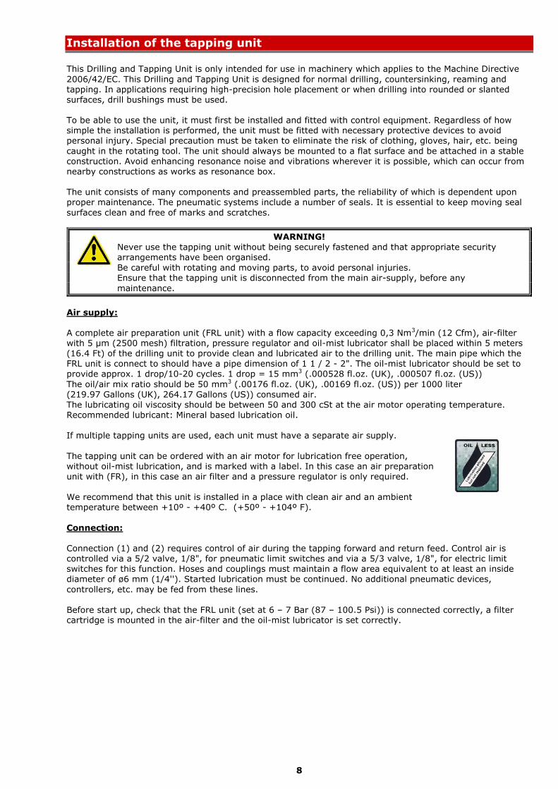
The tapping unit can be ordered with an air motor for lubrication free operation, without oil-mist lubrication, and is marked with a label. In this case an air preparation unit with (FR), in this case an air filter and a pressure regulator is only required. We recommend that this unit is installed in a place with clean air and an ambient temperature between +10º - +40º C. (+50º - +104º F).
Connection:
Connection (1) and (2) requires control of air during the tapping forward and return feed. Control air is controlled via a 5/2 valve, 1/8", for pneumatic limit switches and via a 5/3 valve, 1/8", for electric limit switches for this function. Hoses and couplings must maintain a flow area equivalent to at least an inside diameter of ø6 mm (1/4''). Started lubrication must be continued. No additional pneumatic devices,
controllers, etc. may be fed from these lines. Before start up, check that the FRL unit (set at 6 – 7 Bar (87 – 100.5 Psi)) is connected correctly, a filter cartridge is mounted in the air-filter and the oil-mist lubricator is set correctly.

9
Attachment
The use of E2 Systems monting clamps and brackets for driling units is recommended. If other way of attachment is desired attach the drilling unit according to one of the suggestions 1 or 2 below. The drilling
unit can be mounted vertically or horizontally. Optional attachment should be discussed with E2's technician.
Mounting of cutting tools
The following cutting tools can be used with tapping unit:
Cutting tap or cold forming tap. The tapping unit can be fitted with quick change chuck or multi-spindle head. Quick Change Chuck: Multi-spindle head:

10
Description of limit switches
Tapping unit LS 22 with pneumatic limit switches
Function:
V4 is operated by the forward cam (1). This signal is used for the reversing of the unit. V5 is operated by the rear cam (2). This signal is used for the resetting of the unit.
Explanation: V4 = Pneumatic micro-switch for forward position. V5 = Pneumatic micro-switch for rear position.
V4-1 = Connected to contant air supply ( 6 – 7 Bars ( 87 – 101.5 Psi ).
V4-2 = Connected to Valve V1 – 14. V5-3 = Connected to Port 1 on the tapping unit. V5-4 = Connected to Valve V2 – 12.
Tapping unit LS 22 with electric limit switches
Function:
M1 is operated by the forward cam (1). This signal is used for the reversing of the unit.
M2 is operated by the rear cam (2). This signal is used for the resetting of the unit.
Explanation: The electric micro-switches M1 and M2 are universally connected to a 7-pole male plug for normally closed and normally open functions and requires no internal access work.
During installation, only the supplied plug has to be connected to desired connection for the desired function as below table: M2, pin 1 – 2 opening.
M2, pin 1 – 3 closing. M1, pin 4 – 5 opening. M1, pin 4 – 6 closing.
Centre pin is for earthing.
WARNING!
Before any adjustments are made, make sure that the electrical power to the limit switch is cut off.

11
Micro-switches
If conversion from electrical to pneumatic micro-switches, or vice versa, is required, cam (1) and cam ring
(2) two modes. By screwing out and change the location of the grub screws (3) and rotate the cam (1) and cam (2) 180º electric or pneumatic mode is provided.
Setting of thread depth and rear position
The thread depth (return position) is set by placing cam (1) in the right slot on the signal rod (2). The cam is locked in the slot with grub screw (3). NOTE! In certain positions the threaded part (4) of the cam must screwed out to reach the grub screw. Fine setting is pefromed with the threaded part of the cam (4). One revolution on the cam corresponds is 1 mm (.039 In). The rear position is set with cam (5).

12
Example of connection with limit switch
Pneumatic:
Electric:
13
Maintenance instruction
Daily check:
- Check the air-pressure on the FRL-unit, 6 – 7 bar (87 – 101.5 Psi). Max 7 bar (101.5 Psi). - Check for any leakages of air. If a leakage is detected, contact service staff. Weekly check: - Check that the oil-mist lubrication is working, approx. 1 drop/10-20 cycles. 1 drop = 15 mm3
(.000528 fl.oz. (UK), .000507 fl.oz. (US)) - Check that the tapping unit is clean. Monthly check: - Check that no abnormal play is present in the tapping spindle.
Every six months:
- Check that the air filter in the FRL unit is working or replace the air filter. Every 12 months:
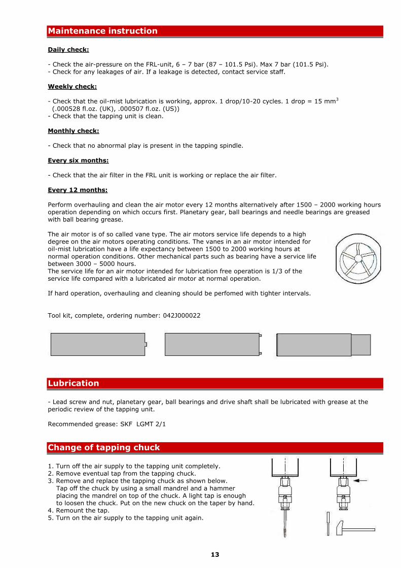
Perform overhauling and clean the air motor every 12 months alternatively after 1500 – 2000 working hours operation depending on which occurs first. Planetary gear, ball bearings and needle bearings are greased with ball bearing grease. The air motor is of so called vane type. The air motors service life depends to a high degree on the air motors operating conditions. The vanes in an air motor intended for oil-mist lubrication have a life expectancy between 1500 to 2000 working hours at
normal operation conditions. Other mechanical parts such as bearing have a service life between 3000 – 5000 hours. The service life for an air motor intended for lubrication free operation is 1/3 of the
service life compared with a lubricated air motor at normal operation. If hard operation, overhauling and cleaning should be perfomed with tighter intervals.
Tool kit, complete, ordering number: 042J000022
Lubrication
- Lead screw and nut, planetary gear, ball bearings and drive shaft shall be lubricated with grease at the periodic review of the tapping unit.
Recommended grease: SKF LGMT 2/1
Change of tapping chuck
1. Turn off the air supply to the tapping unit completely. 2. Remove eventual tap from the tapping chuck. 3. Remove and replace the tapping chuck as shown below.
Tap off the chuck by using a small mandrel and a hammer
placing the mandrel on top of the chuck. A light tap is enough to loosen the chuck. Put on the new chuck on the taper by hand. 4. Remount the tap. 5. Turn on the air supply to the tapping unit again.

14
Change of lead screw and nut
NOTE! The lead screw and nut are made individually as a pair, why these always are replaced together.
Change of lead screw and nut is carried out as follows: 1. Set the tapping unit in its rear position, ”home position”. 2. Remove any tapping chuck from lead screw.
3. Loosen and remove the screws (3, 4 and 5). 4. Separate the front house (1) from the motor house (2). 5. Remove the lead screw (7) and lead screw nut (8).
6. Exchange the lead screw (7) and lead screw nut (8).
NOTE! Important dimension for the fitting.
Ensure that new lubricant (ball bearing grease) is applied in the space (9) in front of the lead screw nut (8) and on the lead screws (7) threads and internally on the drive spline shaft (10) and fork (11).
7. Mount the lead screw (7) and lead screw nut (8). 8. Assemble the front house (1) and motor house (2).
9. Mount and tighten screws (3, 4 and 5).
10. Put back any tapping chuck on the lead screw.

15
Type Power,
kW
Power,
Hp
LS 223 0,16 0,21
LS 225 0,16 0,21
LS 226 0,16 0,21
LS 2213 0,16 0,21
LS 2221 0,16 0,21
LS 2228 0,16 0,21
Type
Speed *
(idle)
Rpm
Speed
(at max
power) Rpm
Torque
(at min
start) Nm
Torque
(at min
start)
Lbf-in
Torque
(at max
power)
Nm
Torque
(at max
power)
Lbf-in
LS 223 240 140 13,4 119 10,8 96
LS 225 400 240 8,0 71 6,7 59
LS 226 540 310 5,9 52 5,0 44
LS 2213 1050 650 3,0 27 2,4 21
LS 2221 1750 1050 1,8 16 1,5 13,2
LS 2228 2400 1390 1,3 11,5 1,1 9,7 * Lubrication free air motors have 95% of shown idle speed.
Technical information
Technical features, at 6,3 Bar (91.35 Psi):
Power, air motor : See Power table below. Stroke : Max. 51 mm (2''), 100% controlled. CC spindle spacing : Single spindle min. 42 mm (1 5/8") Double spindle head min. 11 mm (7/16") Depth, accuracy : +/- 0,01 mm (.0004 In) Working pressure range : 6 – 7 bar. Max 7 bar (85 – 100 Psi. Max. 101.5 Psi)
Air consumption : < 0,3 Nm3/min (< 12 Cfm) Ambient temperature : +10º - +40º C. (+50º - +104º F) Sound level : 70 dB(A) Spindle taper : B12 Electric limit switches : Micro-switch: 10A 125V AC / 10A 250V AC
Power, at 6,3 Bar (91.35 Psi):
Typical air motor caracteristics. Speed and torque, at 6,3 Bar (91.35 Psi):
Maximum power is produced when the drilling spindle during operation rotates at half speed max speed.
For other data such as drilling capacity we refer to our website www.e2systems.com.

16
Dimensional drawing
Multi-spindle head, type A mm B mm C mm Adaptor,
weight Kgs
Adaptor,
weight Lbs
MBKV-402 20 35 117 1,1 2,43
VH 042 22 25 97 1,1 2,43
MBK-6V2 21 56 117 1,1 2,43

17
Spare parts drawing

18
Spare parts list
LS 22
Pos. Qty Description Part no.
1 1 Front housing 042V200012
2 1 Motor housing 042V200013
3 1 Back head 042V300089
4 1 Lid 042V400224
5 1 Lead screw with nut, complete. For B12 taper. Pitch 0,3 mm. 042R722030
5 1 Lead screw with nut, complete. For B12 taper. Pitch 0,35 mm. 042R722035
5 1 Lead screw with nut, complete. For B12 taper. Pitch 0,4 mm. 042R722040
5 1 Lead screw with nut, complete. For B12 taper. Pitch 0,45 mm. 042R722045
5 1 Lead screw with nut, complete. For B12 taper. Pitch 0,5 mm. 042R722050
5 1 Lead screw with nut, complete. For B12 taper. Pitch 0,6 mm. 042R722060
5 1 Lead screw with nut, complete. For B12 taper. Pitch 0,7 mm. 042R722070
5 1 Lead screw with nut, complete. For B12 taper. Pitch 0,8 mm. 042R722080
5 1 Lead screw with nut, complete. For B12 taper. Pitch 1,0 mm. 042R722100
5 1 Lead screw with nut, complete. For B12 taper. Pitch 1,25 mm. 042R722125
5 1 Lead screw with nut, complete. For B12 taper. Pitch 1,5 mm. 042R722150
5 1 Lead screw with nut, complete. For B12 taper. Pitch 14 TPI. 042R922014
5 1 Lead screw with nut, complete. For B12 taper. Pitch 18 TPI. 042R922018
5 1 Lead screw with nut, complete. For B12 taper. Pitch 20 TPI. 042R922020
5 1 Lead screw with nut, complete. For B12 taper. Pitch 24 TPI. 042R922024
5 1 Lead screw with nut, complete. For B12 taper. Pitch 28 TPI. 042R922028
5 1 Lead screw with nut, complete. For B12 taper. Pitch 32 TPI. 042R922032
5 1 Lead screw with nut, complete. For B12 taper. Pitch 40 TPI. 042R922040
5 1 Lead screw with nut, complete. For B12 taper. Pitch 56 TPI. 042R922056
5 1 Lead screw with nut, complete. For B12 taper. Pitch 72 TPI. 042R922072
5 1 Lead screw with nut, complete. For B12 taper. Pitch 80 TPI. 042R922080
7 1 Fork 042V400228
8 1 Spline shaft 042V400221
9 1 Lock nut 042V400227
10 2 Screw, MC6S 4x20 FZB 411A122017
11 1 Filter washer, 20x30x1 414A112033
12 1 Glide bearing, DU18x20x15 Se pos. 80, 87
13 1 Mid-section 042V400225
14 1 Silencer, inner. 042V400229
15 1 Silencer, outer. 042V400230
16 1 Silencer insert 042K000001
17 1 Air motor LS 223, 226, 2213 och 2228. 042K000002
17 1 Air motor LS 225 och 2221. 042K000003
17A 1 Set of vanes for oil lubricated air motor, pos. 17, complete. 041R000030

19
Pos. Qty Description Part no.
17A 1 Set of vanes for non-lubricated air motor, pos. 17, complete. 041R000028
17B 3 Bearing kit for air motor, pos. 17, complete. 041R000032
18 1 Signal rod Se pos. 85
19 4 Screw, MC6S 4x6 FZB 411A122015
21 2 Micro-switch, for electric limit switch. 10A 125V AC / 10A 250V AC. 604A000012
21 2 Micro-switch, for pneumatic limit switch. 604A000011
22 4 Screw, MC6S 3x16 FZB 411A121095
23 1 Cam, rear Se pos. 84
24 1 Screw, P6SS 4x5 Se pos. 84
25 1 O-ring, 35,1x1,6 Nitril Se pos. 83, 87
26 2 O-ring, 32,1x1,6 Nitril Se pos. 83, 87
27 1 Limit ring Se pos. 85
28 1 Spring pin, 2,5x12 Se pos. 85
29 1 Cam, setting body Se pos. 86
30 1 Cam, setting nut Se pos. 86
31 1 Pressure spring Se pos. 86
32 1 Radial gasket, 7x14x12 Se pos. 85, 87
33 1 Nut, M6M M6 413A112015
34 2 Screw, MC6S 4x70 FZB 411A121177
35 2 Shoulder screw 411A121136
36 1 Radial gasket R Se pos. 80, 87
37 2 Screw, MC6S 4x10 FZB 411A121101
38 2 Screw, MC6S 4x16 FZB 411A122016
39 1 Cable gland 504A000020
40 2 Gear Se pos. 81, 82
41 1 Ball bearing Se pos. 80, 81, 82
42 1 Ball bearing Se pos. 80, 81, 82
43 1 Planetary shaft LS 223, 225 och 226. Se pos. 81
44 1 Planetary shaft LS 2213, 2221, 2228. Se pos. 82
48 1 Screw, SK6SS 4X4 S pos. 86
49 1 Spiral pin, N 4x14 Se pos. 81, 82
53 1 Insulating plate 604A000013
55 1 Locking nut, Nylon 413A119006
1 Cable, 7x0,25, length 1,2 m (3.94 Ft). 514A000001
1 Plug, 7-pole, male. 5 A 300V AC/DC. 504A000006
1 Plug, 7-pole, female. 5 A 300V AC/DC. 504A000007
1 Quick Change Chuck, WFO/B12, metric. On request. 042J000020
1 Tap holder, SE0/WE0 for WFO/B12. On request. 042JXXXXXX
1 Quick Change Chuck, C12/B12, metric and inch. 042J000029
1 Tap holder, T12 for C12/B12, metric and inch. On request. 042JXXXXXX

20
Pos. Qty Description Part no.
60 1 Quill, for multi-spindle head VH04-. 042V300143
60 1 Quill, for multi-spindle head 6V2. 042V300144
61 1 Multi-spindle housing 042V300142
62 1 Drive shaft, for multi-spindle head VH04-. 042V400316
62 1 Drive shaft, for multi-spindle head 6V2. 042V400320
63 1 Drive coupling 042V400318
64 1 Drive adaptor, for VH04-, 6V2. 042V400317
65 1 Radial gasket, 35x41x4 418A660010
66 3 Ball bearing 419A100030
67 1 Screw, MC6S 4x16 FZB 411A122016
68 1 Circlip, SGA 17 415A151032
69 3 Circlip, SGH 26 415A151033
70 2 Spacer 042V400319
71 4 Screw, MC6S 4x10 FZB 411A121101
72 4 Screw, MC6S 6x16 FZB 411A122039
73 1 Key with pin 041U000066
74 1 Wave washer 414A112020
75 1 Locking ring, for VH04-. 041V400206
Complete kits:
80 1 Bearing kit, complete. 042R005001
81 1 Gear assembly LS 223, 225, 226, complete. 042R005002
82 1 Gear assembly LS 2213, 2221, 2228, complete. 042R005003
83 1 O-ring kit, complete. 042R005007
84 1 Rear cam, complete. 042R005008
85 1 Signal rod, complete. 042R005009
86 1 Front cam, complete. 042R005010
87 1 Seal kit, complete. 042R005012

21
Warranty conditions
The warranty period for the product is 500 000 tapping cycles or 12 months after installation/
commissioning or 18 months after delivery, which of these occurs first, and provided that the product installed/stored in a satisfactory manner and that the product is used in normal operation, the mounting/
clamping and handling conditions. The warranty is not valid if unauthorized change/modification have been performed on the product and that this may make the product unsafe.
Environmental declaration
Tapping unit, Type LS 22
House : Steel Lead screw : Steel Nut : Bronze
Other parts : Aluminium, brass and steel. Gaskets : Rubber
House, lead screw and other metallic parts : Dispose as metal waste; Aluminium, bronze, brass and steel. Gaskets : Dispose as combustable waste.
All information contained in this manual is intended to be correct; however information and data in this manual are subject to change without notice. E2systems makes no warranty of any kind of regard to this information or data. Further, E2systems is not responsible for any omissions or errors or consequential damaged caused by the user of the product. E2systems reserves the right to make manufacturing changes
which may not be included in this manual.