PMU-155W series (February 2017, Rev. 01)
19
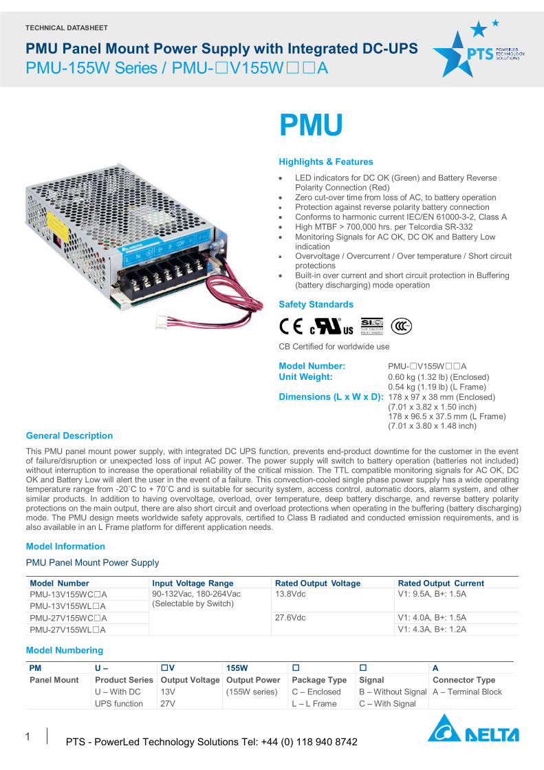
TECHNICAL DATASHEET PMU Panel Mount Power Supply with Integrated DC-UPS PMU-155W Series / PMU-□V155W□□A 1 PMU Highlights & Features • LED indicators for DC OK (Green) and Battery Reverse Polarity Connection (Red) • Zero cut-over time from loss of AC, to battery operation • Protection against reverse polarity battery connection • Conforms to harmonic current IEC/EN 61000-3-2, Class A • High MTBF > 700,000 hrs. per Telcordia SR-332 • Monitoring Signals for AC OK, DC OK and Battery Low indication • Overvoltage / Overcurrent / Over temperature / Short circuit protections • Built-in over current and short circuit protection in Buffering (battery discharging) mode operation Safety Standards CB Certified for worldwide use Model Number: PMU-☐V155W☐☐A Unit Weight: 0.60 kg (1.32 lb) (Enclosed) 0.54 kg (1.19 lb) (L Frame) Dimensions (L x W x D): 178 x 97 x 38 mm (Enclosed) (7.01 x 3.82 x 1.50 inch) 178 x 96.5 x 37.5 mm (L Frame) (7.01 x 3.80 x 1.48 inch) General Description This PMU panel mount power supply, with integrated DC UPS function, prevents end-product downtime for the customer in the event of failure/disruption or unexpected loss of input AC power. The power supply will switch to battery operation (batteries not included) without interruption to increase the operational reliability of the critical mission. The TTL compatible monitoring signals for AC OK, DC OK and Battery Low will alert the user in the event of a failure. This convection-cooled single phase power supply has a wide operating temperature range from -20˚C to + 70˚C and is suitable for security system, access control, automatic doors, alarm system, and other similar products. In addition to having overvoltage, overload, over temperature, deep battery discharge, and reverse battery polarity protections on the main output, there are also short circuit and overload protections when operating in the buffering (battery discharging) mode. The PMU design meets worldwide safety approvals, certified to Class B radiated and conducted emission requirements, and is also available in an L Frame platform for different application needs. Model Information PMU Panel Mount Power Supply Model Number Input Voltage Range Rated Output V oltage Rated Output Current PMU-13V155WC☐A 90-132Vac, 180-264Vac (Selectable by Switch) 13.8Vdc V1: 9.5A, B+: 1.5A PMU-13V155WL☐A PMU-27V155WC☐A 27.6Vdc V1: 4.0A, B+: 1.5A PMU-27V155WL☐A V1: 4.3A, B+: 1.2A Model Numbering PM U – □V 155W □ □ A Panel Mount Product Series U – With DC UPS function Output Voltage 13V 27V Output Power (155W series) Package Type C – Enclosed L – L Frame Signal B – Without Signal C – With Signal Connector Type A – Terminal Block PTS - PowerLed Technology Solutions Tel: +44 (0) 118 940 8742
Transcript of PMU-155W series (February 2017, Rev. 01)
TECHNICAL DATASHEET
PMU Panel Mount Power Supply with Integrated DC-UPS PMU-155W Series / PMU-□V155W□□A
1
PMU Highlights & Features • LED indicators for DC OK (Green) and Battery Reverse
Polarity Connection (Red) • Zero cut-over time from loss of AC, to battery operation • Protection against reverse polarity battery connection • Conforms to harmonic current IEC/EN 61000-3-2, Class A • High MTBF > 700,000 hrs. per Telcordia SR-332 • Monitoring Signals for AC OK, DC OK and Battery Low
indication • Overvoltage / Overcurrent / Over temperature / Short circuit
protections • Built-in over current and short circuit protection in Buffering
(battery discharging) mode operation
Safety Standards
CB Certified for worldwide use
Model Number: PMU-☐V155W☐☐A Unit Weight: 0.60 kg (1.32 lb) (Enclosed) 0.54 kg (1.19 lb) (L Frame) Dimensions (L x W x D): 178 x 97 x 38 mm (Enclosed)
(7.01 x 3.82 x 1.50 inch) 178 x 96.5 x 37.5 mm (L Frame)
(7.01 x 3.80 x 1.48 inch) General Description This PMU panel mount power supply, with integrated DC UPS function, prevents end-product downtime for the customer in the event of failure/disruption or unexpected loss of input AC power. The power supply will switch to battery operation (batteries not included) without interruption to increase the operational reliability of the critical mission. The TTL compatible monitoring signals for AC OK, DC OK and Battery Low will alert the user in the event of a failure. This convection-cooled single phase power supply has a wide operating temperature range from -20˚C to + 70˚C and is suitable for security system, access control, automatic doors, alarm system, and other similar products. In addition to having overvoltage, overload, over temperature, deep battery discharge, and reverse battery polarity protections on the main output, there are also short circuit and overload protections when operating in the buffering (battery discharging) mode. The PMU design meets worldwide safety approvals, certified to Class B radiated and conducted emission requirements, and is also available in an L Frame platform for different application needs. Model Information
PMU Panel Mount Power Supply Model Number Input Voltage Range Rated Output Voltage Rated Output Current PMU-13V155WC☐A 90-132Vac, 180-264Vac
(Selectable by Switch) 13.8Vdc V1: 9.5A, B+: 1.5A
PMU-13V155WL☐A PMU-27V155WC☐A 27.6Vdc V1: 4.0A, B+: 1.5A
PMU-27V155WL☐A V1: 4.3A, B+: 1.2A
Model Numbering
PM U – □V 155W □ □ A Panel Mount Product Series
U – With DC UPS function
Output Voltage 13V 27V
Output Power (155W series)
Package Type C – Enclosed L – L Frame
Signal B – Without Signal C – With Signal
Connector Type A – Terminal Block
PTS - PowerLed Technology Solutions Tel: +44 (0) 118 940 8742
TECHNICAL DATASHEET
PMU-155W Series / PMU-□V155W□□A
2
Specifications
Model Number PMU-13V155W☐☐A PMU-27V155W☐☐A V1 B+ V1 B+
Input Ratings / Characteristics Nominal Input Voltage 100-120Vac, 200-240Vac (Selectable by Switch) Input Voltage Range 90-132Vac, 180-264Vac (Selectable by Switch)
For power de-rating at 90-132Vac, see power de-rating on page 5. Nominal Input Frequency 50-60Hz Input Frequency Range 47-63Hz Input Current < 2.5A @ 115Vac, < 1.5A @ 230Vac Efficiency at 100% Load > 85.0% @ 115Vac
> 86.0% @ 230Vac > 88.0% @ 115Vac > 89.0% @ 230Vac
Max Power Dissipation No Load < 0.4W @ 115Vac < 0.5W @ 230Vac
< 0.6W @ 115Vac < 0.7W @ 230Vac
100% Load < 23W @ 115Vac & 230Vac < 19W @ 115Vac & 230Vac Max Inrush Current (Cold Start) < 25A @ 115Vac & 230Vac Leakage Current < 0.5mA @ 264Vac
Output Ratings / Characteristics1) Nominal Output Voltage 13.8Vdc 13.3Vdc2) 27.6Vdc 27.1Vdc2) Factory Set Point Tolerance ± 2% Output Voltage Adjustment Range 12-14Vdc - 24-28Vdc - Output Current3) Enclosed Normal Mode 9.5A (0-11A) 1.5A (0.5-1.5A) 4.0A (0-5.5A) 1.5A (0.5-1.5A) Buffering Mode - 11A - 5.5A L Frame Normal Mode 9.5A (0-11A) 1.5A (0.5-1.5A) 4.3A (0-5.5A) 1.2A (0.5-1.2A) Buffering Mode - 11A - 5.5A Output Power 151W (max) Line Regulation V1 < 0.5% (90-132Vac @ 90% load,180-264Vac @ 100% load) Load Regulation V1 < 1.0% (90-132Vac @ 0-90% load,180-264Vac @ 0-100% load) PARD4) (20MHz) V1 < 150mVpp @ 0°C to -20°C
< 100mVpp @ > 0°C to 70°C Rise Time V1 < 50ms (100Vac @ 90% load, 200Vac @ 100% load) Start-up Time V1 < 1,000ms (115Vac @ 90% load, 230Vac @ 100% load) Hold-up Time V1 > 20ms (115Vac @ 90% load, 230Vac @ 100% load) Dynamic Response (Overshoot & Undershoot O/P Voltage)
V1 ± 5%, 0-50% & 50-100% & 10-100% load (Slew Rate: 0.1A/μS, 50% duty cycle @ 5Hz to 1KHz)
Start-up with Capacitive Loads
V1 3,600µF at 13.8V/11A 3,600µF at 27.6V/5.5A Voltage Drop Between V1 and B+ Normal Mode 0.5V typ.
Buffering Mode 0.2V typ. Series Operation No Parallel Operation No
1) For power de-rating from < 0°C to -20°C, and 50°C to 70°C, and power de-rating at input voltage, see power de-rating on page 11. 2) If a battery is not connected to B+ and B-, when PMU is turned on, a voltage cannot be seen at these terminals. 3) The maximum combined output power from V1 and B+ is 151W at 180-264Vac input but the output power is reduced to 136W at 90-132Vac input For example; 151W; V1: 27.6V/4A (110.4W), B+: 27.1V/1.5A (40.6) or V1: 27.6V/5.5A (151W), B+: 27.1V/0A (0W). 136W; V1: 27.6V/3.45A (95.2W), B+: 27.1V/1.5A (40.6) or V1: 27.6V/4.9A (136W), B+: 27.1V/0A (0W). Battery charging current at B+ output can be adjusted according to output current range in parentheses by battery charging current adjustment potentiometer. Load range in parentheses and rated current outside parentheses. 4) PARD is measured with an AC coupling mode, 5cm wires, and in parallel with 0.1µF ceramic capacitor & 47µF electrolytic capacitor.
PTS - PowerLed Technology Solutions Tel: +44 (0) 118 940 8742
TECHNICAL DATASHEET
PMU Panel Mount Power Supply with Integrated DC-UPS PMU-155W Series / PMU-□V155W□□A
3
Model Number PMU-13V155W☐☐A PMU-27V155W☐☐A V1 B+ V1 B+
Battery Input / Output Characteristics Nominal Battery Voltage (Batteries not included with power supply)
12Vdc SLA Sealed lead acid battery
24Vdc SLA Sealed lead acid battery 2 x 12Vdc SLA Sealed lead acid battery
Battery Voltage Range Continuously Operating
11.0 to 13.8Vdc (nominal at 12V)
22.0 to 27.6Vdc (nominal at 24V)
Maximum Allowed Voltage
16Vdc Max 32Vdc Max
Minimum Voltage1)
8.5Vdc 16.5Vdc
Battery Capacity 3.3AH/ 7AH/ 12AH/ 15AH Charging Time2) 2-10 hrs @ charging current of 1.5A Recommended External Fuse for Battery PMU-13V155W☐☐A
Automotive 30A / 80V FK3 type from Littelfuse, or similar, in the battery B+ path. The battery fuse protects the wires between the battery and the unit. PMU-27V155W☐☐A Automotive 30A / 80V FK3 type from Littelfuse, or similar, in the battery B+ path. The battery fuse protects the wires between the battery and the unit. Battery Charging (Normal Mode) CC-CV mode (constant current-constant voltage) at 0 to 1.5A
End-of-Charge Voltage The unit always charges battery to a fixed voltage value Mechanical Case Chassis / Cover AL / SGCC Dimensions (L x W x D) Enclosed 178 x 97 x 38 mm (7.01 x 3.82 x 1.50 inch) L Frame 178 x 96.5 x 37.5 mm (7.01 x 3.80 x 1.48 inch) Unit Weight Enclosed 0.60 kg (1.32 lb) L Frame 0.54 kg (1.19 lb) LED Indicator Green LED DC OK
Red LED Battery Connected in Reverse Polarity Cooling System Convection Terminal M3.5 x 7 Pins (Rated 300V/15A) Signal JST: XHP-4 (PMU-☐V155W☐CA)
Wire AWG 16-14 Noise (1 Meter from power supply) Sound Pressure Level (SPL) < 30dBA
1) Minimum battery voltage required for power supply to detect battery in order to begin charging. Battery must be connected to power supply, with the correct polarity, across B+ and B- terminals; and, with input and output loads disconnected. 2) Charging time depends on the state/condition of battery discharge; and will depend on the amount of buffering/discharging time, and load current that battery was discharged at.
PTS - PowerLed Technology Solutions Tel: +44 (0) 118 940 8742
TECHNICAL DATASHEET
PMU Panel Mount Power Supply with Integrated DC-UPS PMU-155W Series / PMU-□V155W□□A
4
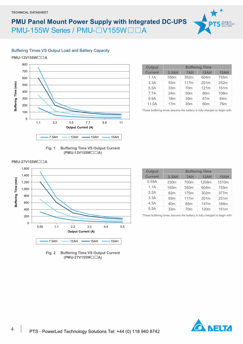
Buffering Times VS Output Load and Battery Capacity
PMU-13V155W☐☐A
Output Current
Buffering Time 3.3AH 7AH 12AH 15AH
1.1A 166m 352m 604m 755m 3.3A 55m 117m 201m 252m 5.5A 33m 70m 121m 151m 7.7A 24m 50m 86m 108m 9.9A 18m 39m 67m 84m 11.0A 17m 35m 60m 76m
PMU-27V155W☐☐A
Output Current
Buffering Time 3.3AH 7AH 12AH 15AH
0.55A 330m 700m 1208m 1510m 1.1A 165m 350m 604m 755m 2.2A 82m 175m 302m 377m 3.3A 55m 117m 201m 251m 4.5A 40m 85m 147m 184m 5.5A 33m 70m 120m 151m
0
100
200
300
400
500
600
700
800
1.1 3.3 5.5 7.7 9.9 11
Buffe
ring
Tim
e (m
in)
Output Current (A)
7.5AH 12AH 15AH 15AH
0
200
400
600
800
1,000
1,200
1,400
1,600
0.55 1.1 2.2 3.3 4.5 5.5
Buffe
ring
Tim
e (m
in)
Output Current (A)
7.5AH 12AH 15AH 15AH
Fig. 1 Buffering Time VS Output Current (PMU-13V155W☐☐A)
Fig. 2 Buffering Time VS Output Current (PMU-27V155W☐☐A)
These buffering times assume the battery is fully charged to begin with
These buffering times assume the battery is fully charged to begin with
PTS - PowerLed Technology Solutions Tel: +44 (0) 118 940 8742
TECHNICAL DATASHEET
PMU Panel Mount Power Supply with Integrated DC-UPS PMU-155W Series / PMU-□V155W□□A
5
Model Number PMU-13V155W☐☐A PMU-27V155W☐☐A V1 B+ V1 B+
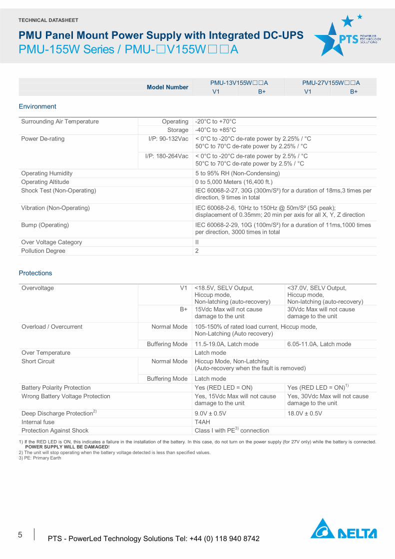
Environment Surrounding Air Temperature Operating -20°C to +70°C
Storage -40°C to +85°C Power De-rating I/P: 90-132Vac < 0°C to -20°C de-rate power by 2.25% / °C
50°C to 70°C de-rate power by 2.25% / °C I/P: 180-264Vac < 0°C to -20°C de-rate power by 2.5% / °C
50°C to 70°C de-rate power by 2.5% / °C Operating Humidity 5 to 95% RH (Non-Condensing) Operating Altitude 0 to 5,000 Meters (16,400 ft.) Shock Test (Non-Operating) IEC 60068-2-27, 30G (300m/S²) for a duration of 18ms,3 times per
direction, 9 times in total
Vibration (Non-Operating) IEC 60068-2-6, 10Hz to 150Hz @ 50m/S² (5G peak); displacement of 0.35mm; 20 min per axis for all X, Y, Z direction
Bump (Operating) IEC 60068-2-29, 10G (100m/S²) for a duration of 11ms,1000 times per direction, 3000 times in total
Over Voltage Category II Pollution Degree 2
Protections Overvoltage V1 <18.5V, SELV Output,
Hiccup mode, Non-latching (auto-recovery)
<37.0V, SELV Output, Hiccup mode, Non-latching (auto-recovery)
B+ 15Vdc Max will not cause damage to the unit
30Vdc Max will not cause damage to the unit
Overload / Overcurrent Normal Mode
105-150% of rated load current, Hiccup mode, Non-Latching (Auto recovery)
Buffering Mode 11.5-19.0A, Latch mode 6.05-11.0A, Latch mode Over Temperature Latch mode Short Circuit Normal Mode Hiccup Mode, Non-Latching
(Auto-recovery when the fault is removed)
Buffering Mode Latch mode Battery Polarity Protection Yes (RED LED = ON) Yes (RED LED = ON)1) Wrong Battery Voltage Protection Yes, 15Vdc Max will not cause
damage to the unit Yes, 30Vdc Max will not cause damage to the unit
Deep Discharge Protection2) 9.0V ± 0.5V 18.0V ± 0.5V Internal fuse T4AH Protection Against Shock Class I with PE3) connection
1) If the RED LED is ON, this indicates a failure in the installation of the battery. In this case, do not turn on the power supply (for 27V only) while the battery is connected. POWER SUPPLY WILL BE DAMAGED! 2) The unit will stop operating when the battery voltage detected is less than specified values. 3) PE: Primary Earth
PTS - PowerLed Technology Solutions Tel: +44 (0) 118 940 8742
TECHNICAL DATASHEET
PMU Panel Mount Power Supply with Integrated DC-UPS PMU-155W Series / PMU-□V155W□□A
6
Model Number PMU-13V155W☐☐A PMU-27V155W☐☐A V1 B+ V1 B+
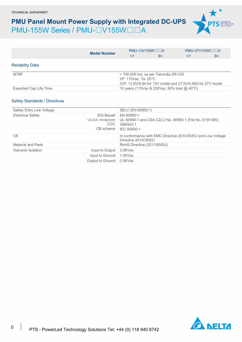
Reliability Data MTBF > 700,000 hrs. as per Telcordia SR-332
I/P: 115Vac, Ta: 25°C O/P: 13.8V/9.9A for 13V model and 27.6V/4.95A for 27V model
Expected Cap Life Time 10 years (115Vac & 230Vac, 50% load @ 40°C)
Safety Standards / Directives Safety Entry Low Voltage SELV (EN 60950-1) Electrical Safety SIQ Bauart
UL/cUL recognized CCC
CB scheme
EN 60950-1 UL 60950-1 and CSA C22.2 No. 60950-1 (File No. E191395) GB4943.1 IEC 60950-1
CE In conformance with EMC Directive 2014/30/EU and Low Voltage Directive 2014/35/EU
Material and Parts RoHS Directive (2011/65/EU) Galvanic Isolation Input to Output 3.0KVac
Input to Ground 1.5KVac Output to Ground 0.5KVac
PTS - PowerLed Technology Solutions Tel: +44 (0) 118 940 8742
TECHNICAL DATASHEET
PMU Panel Mount Power Supply with Integrated DC-UPS PMU-155W Series / PMU-□V155W□□A
7
Model Number PMU-13V155W☐☐A PMU-27V155W☐☐A V1 B+ V1 B+
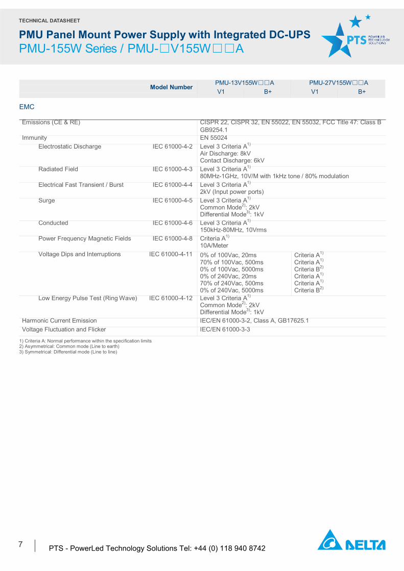
EMC Emissions (CE & RE) CISPR 22, CISPR 32, EN 55022, EN 55032, FCC Title 47: Class B
GB9254.1 Immunity EN 55024
Electrostatic Discharge IEC 61000-4-2 Level 3 Criteria A1) Air Discharge: 8kV Contact Discharge: 6kV
Radiated Field IEC 61000-4-3 Level 3 Criteria A1) 80MHz-1GHz, 10V/M with 1kHz tone / 80% modulation
Electrical Fast Transient / Burst IEC 61000-4-4 Level 3 Criteria A1) 2kV (Input power ports)
Surge IEC 61000-4-5 Level 3 Criteria A1) Common Mode2): 2kV Differential Mode3): 1kV
Conducted IEC 61000-4-6 Level 3 Criteria A1) 150kHz-80MHz, 10Vrms
Power Frequency Magnetic Fields IEC 61000-4-8 Criteria A1) 10A/Meter
Voltage Dips and Interruptions IEC 61000-4-11 0% of 100Vac, 20ms 70% of 100Vac, 500ms 0% of 100Vac, 5000ms 0% of 240Vac, 20ms 70% of 240Vac, 500ms 0% of 240Vac, 5000ms
Criteria A1) Criteria A1) Criteria B2) Criteria A1) Criteria A1) Criteria B2)
Low Energy Pulse Test (Ring Wave) IEC 61000-4-12 Level 3 Criteria A1) Common Mode2): 2kV Differential Mode3): 1kV
Harmonic Current Emission IEC/EN 61000-3-2, Class A, GB17625.1 Voltage Fluctuation and Flicker IEC/EN 61000-3-3
1) Criteria A: Normal performance within the specification limits 2) Asymmetrical: Common mode (Line to earth) 3) Symmetrical: Differential mode (Line to line)
PTS - PowerLed Technology Solutions Tel: +44 (0) 118 940 8742
TECHNICAL DATASHEET
PMU Panel Mount Power Supply with Integrated DC-UPS PMU-155W Series / PMU-□V155W□□A
8
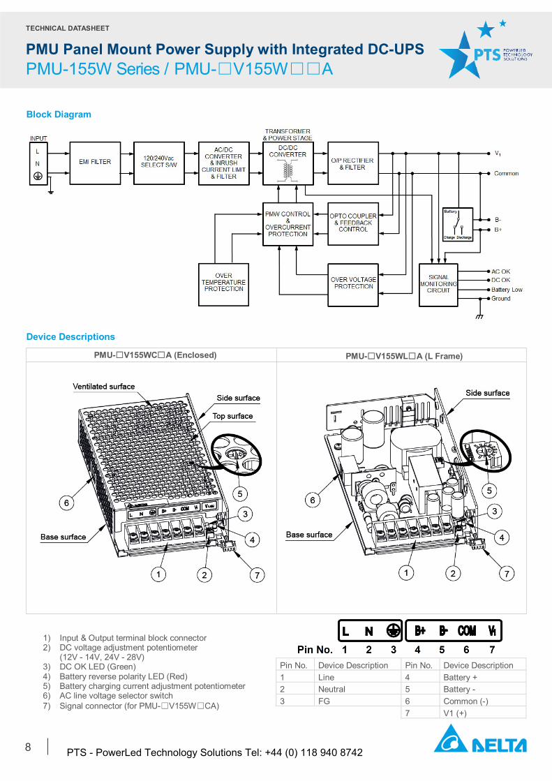
Block Diagram
Device Descriptions
1) Input & Output terminal block connector 2) DC voltage adjustment potentiometer
(12V - 14V, 24V - 28V) 3) DC OK LED (Green) 4) Battery reverse polarity LED (Red) 5) Battery charging current adjustment potentiometer 6) AC line voltage selector switch 7) Signal connector (for PMU-☐V155W☐CA)
Pin No. Device Description Pin No. Device Description 1 Line 4 Battery + 2 Neutral 5 Battery - 3 FG 6 Common (-) 7 V1 (+)
PMU-☐V155WC☐A (Enclosed) PMU-☐V155WL☐A (L Frame)
PTS - PowerLed Technology Solutions Tel: +44 (0) 118 940 8742
TECHNICAL DATASHEET
PMU Panel Mount Power Supply with Integrated DC-UPS PMU-155W Series / PMU-□V155W□□A
9
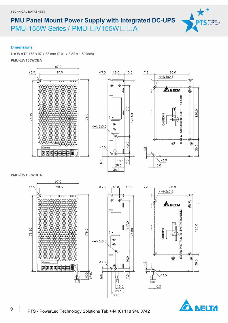
Dimensions
L x W x D: 178 x 97 x 38 mm (7.01 x 3.82 x 1.50 inch)
PMU-☐V155WCBA
PMU-☐V155WCCA
PTS - PowerLed Technology Solutions Tel: +44 (0) 118 940 8742
TECHNICAL DATASHEET
PMU Panel Mount Power Supply with Integrated DC-UPS PMU-155W Series / PMU-□V155W□□A
10
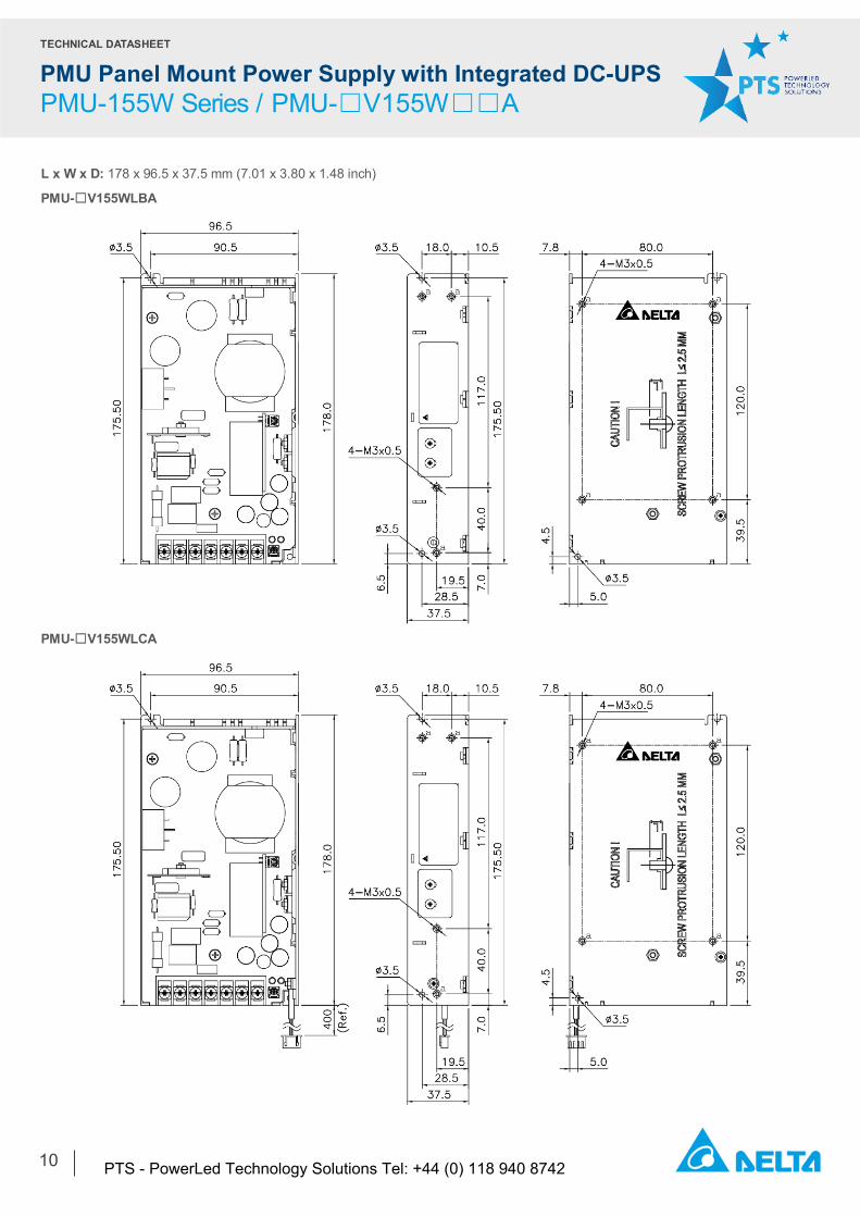
L x W x D: 178 x 96.5 x 37.5 mm (7.01 x 3.80 x 1.48 inch)
PMU-☐V155WLBA
PMU-☐V155WLCA
PTS - PowerLed Technology Solutions Tel: +44 (0) 118 940 8742
TECHNICAL DATASHEET
PMU Panel Mount Power Supply with Integrated DC-UPS PMU-155W Series / PMU-□V155W□□A
11
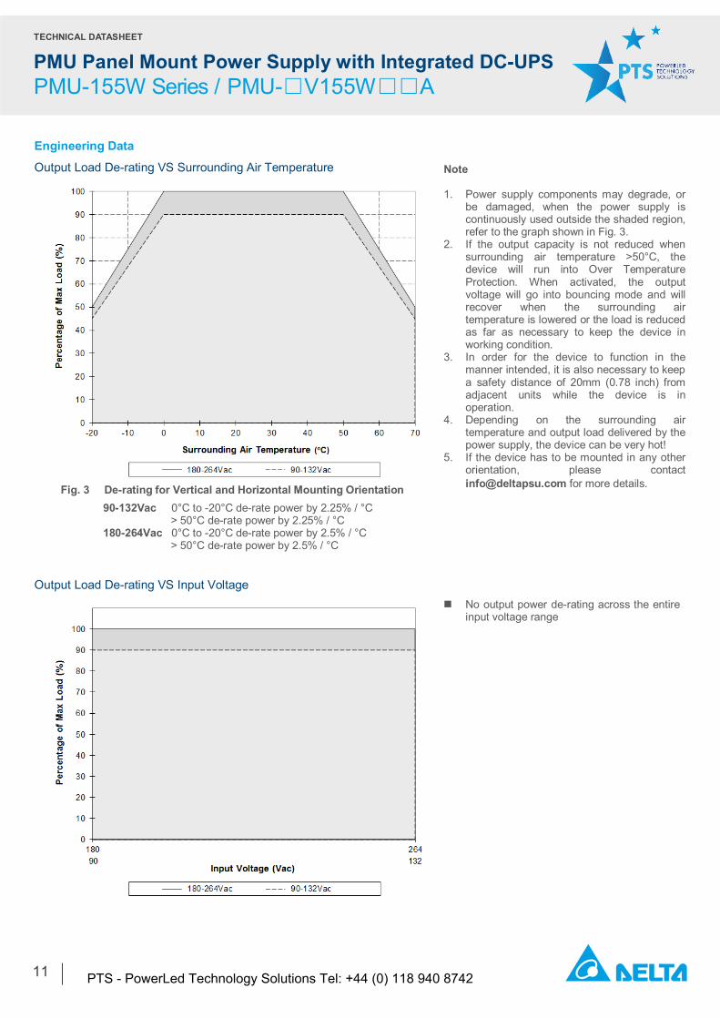
Engineering Data
Output Load De-rating VS Surrounding Air Temperature
Output Load De-rating VS Input Voltage
Fig. 3 De-rating for Vertical and Horizontal Mounting Orientation
90-132Vac 0°C to -20°C de-rate power by 2.25% / °C > 50°C de-rate power by 2.25% / °C
180-264Vac 0°C to -20°C de-rate power by 2.5% / °C > 50°C de-rate power by 2.5% / °C
Note 1. Power supply components may degrade, or
be damaged, when the power supply is continuously used outside the shaded region, refer to the graph shown in Fig. 3.
2. If the output capacity is not reduced when surrounding air temperature >50°C, the device will run into Over Temperature Protection. When activated, the output voltage will go into bouncing mode and will recover when the surrounding air temperature is lowered or the load is reduced as far as necessary to keep the device in working condition.
3. In order for the device to function in the manner intended, it is also necessary to keep a safety distance of 20mm (0.78 inch) from adjacent units while the device is in operation.
4. Depending on the surrounding air temperature and output load delivered by the power supply, the device can be very hot!
5. If the device has to be mounted in any other orientation, please contact [email protected] for more details.
No output power de-rating across the entire input voltage range
PTS - PowerLed Technology Solutions Tel: +44 (0) 118 940 8742
TECHNICAL DATASHEET
PMU Panel Mount Power Supply with Integrated DC-UPS PMU-155W Series / PMU-□V155W□□A
12
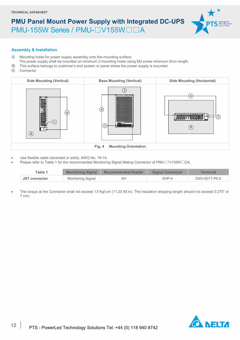
Assembly & Installation Ⓐ Mounting holes for power supply assembly onto the mounting surface. The power supply shall be mounted on minimum 2 mounting holes using M3 screw minimum 5mm length. Ⓑ This surface belongs to customer’s end system or panel where the power supply is mounted. Ⓒ Connector
Side Mounting (Vertical) Base Mounting (Vertical) Side Mounting (Horizontal)
Fig. 4 Mounting Orientation • Use flexible cable (stranded or solid), AWG No. 16-14. • Please refer to Table 1 for the recommended Monitoring Signal Mating Connector of PMU-☐V155W☐CA.
Table 1 Monitoring Signal Recommended Header Signal Connector Terminal
JST connector Monitoring Signal XH XHP-4 SXH-001T-P0.6
• The torque at the Connector shall not exceed 13 Kgf.cm (11.23 lbf.in). The insulation stripping length should not exceed 0.275” or 7 mm.
PTS - PowerLed Technology Solutions Tel: +44 (0) 118 940 8742
TECHNICAL DATASHEET
PMU Panel Mount Power Supply with Integrated DC-UPS PMU-155W Series / PMU-□V155W□□A
13
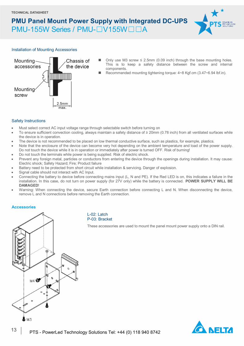
Installation of Mounting Accessories
Safety Instructions
• Must select correct AC input voltage range through selectable switch before turning on • To ensure sufficient convection cooling, always maintain a safety distance of ≥ 20mm (0.78 inch) from all ventilated surfaces while
the device is in operation. • The device is not recommended to be placed on low thermal conductive surface, such as plastics, for example, plastics. • Note that the enclosure of the device can become very hot depending on the ambient temperature and load of the power supply.
Do not touch the device while it is in operation or immediately after power is turned OFF. Risk of burning! • Do not touch the terminals while power is being supplied. Risk of electric shock. • Prevent any foreign metal, particles or conductors from entering the device through the openings during installation. It may cause:
Electric shock; Safety Hazard; Fire; Product failure • Battery need to be protected from short circuit while installation & servicing. Danger of explosion. • Signal cable should not interact with AC Input. • Connecting the battery to device before connecting mains input (L, N and PE). If the Red LED is on, this indicates a failure in the
installation. In this case, do not turn on power supply (for 27V only) while the battery is connected. POWER SUPPLY WILL BE DAMAGED!
• Warning: When connecting the device, secure Earth connection before connecting L and N. When disconnecting the device, remove L and N connections before removing the Earth connection.
Accessories
L-02: Latch P-03: Bracket These accessories are used to mount the panel mount power supply onto a DIN rail.
Only use M3 screw ≤ 2.5mm (0.09 inch) through the base mounting holes. This is to keep a safety distance between the screw and internal components.
Recommended mounting tightening torque: 4~8 Kgf.cm (3.47~6.94 lbf.in).
PTS - PowerLed Technology Solutions Tel: +44 (0) 118 940 8742
TECHNICAL DATASHEET
PMU Panel Mount Power Supply with Integrated DC-UPS PMU-155W Series / PMU-□V155W□□A
14
Functions
Monitoring Signal Characteristics
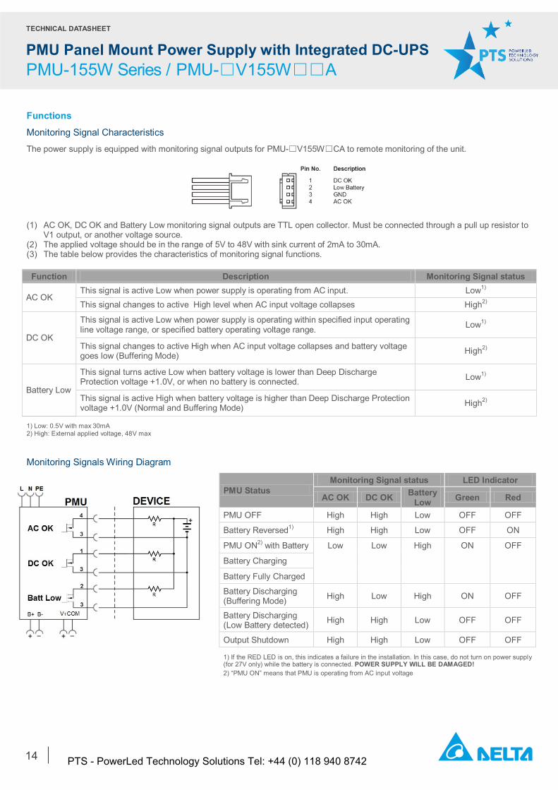
The power supply is equipped with monitoring signal outputs for PMU-☐V155W☐CA to remote monitoring of the unit.
(1) AC OK, DC OK and Battery Low monitoring signal outputs are TTL open collector. Must be connected through a pull up resistor to
V1 output, or another voltage source. (2) The applied voltage should be in the range of 5V to 48V with sink current of 2mA to 30mA. (3) The table below provides the characteristics of monitoring signal functions.
Function Description Monitoring Signal status
AC OK This signal is active Low when power supply is operating from AC input. Low1) This signal changes to active High level when AC input voltage collapses High2)
DC OK
This signal is active Low when power supply is operating within specified input operating line voltage range, or specified battery operating voltage range. Low1)
This signal changes to active High when AC input voltage collapses and battery voltage goes low (Buffering Mode) High2)
Battery Low
This signal turns active Low when battery voltage is lower than Deep Discharge Protection voltage +1.0V, or when no battery is connected. Low1)
This signal is active High when battery voltage is higher than Deep Discharge Protection voltage +1.0V (Normal and Buffering Mode) High2)
1) Low: 0.5V with max 30mA 2) High: External applied voltage, 48V max Monitoring Signals Wiring Diagram
PMU Status Monitoring Signal status LED Indicator
AC OK DC OK Battery Low Green Red
PMU OFF High High Low OFF OFF
Battery Reversed1) High High Low OFF ON
PMU ON2) with Battery Low Low High ON OFF
Battery Charging
Battery Fully Charged
Battery Discharging (Buffering Mode) High Low High ON OFF
Battery Discharging (Low Battery detected) High High Low OFF OFF
Output Shutdown High High Low OFF OFF
1) If the RED LED is on, this indicates a failure in the installation. In this case, do not turn on power supply (for 27V only) while the battery is connected. POWER SUPPLY WILL BE DAMAGED! 2) “PMU ON” means that PMU is operating from AC input voltage
PTS - PowerLed Technology Solutions Tel: +44 (0) 118 940 8742

TECHNICAL DATASHEET
PMU Panel Mount Power Supply with Integrated DC-UPS PMU-155W Series / PMU-□V155W□□A
15
Normal Mode (Power supply (V1) and Battery charging (B+)) Buffering Mode (Battery discharging (B+))
The maximum combined output power from V1 and B+ is 151W at 180-264Vac input but the output power is reduced to 136W at 90-132Vac input. For example; 151W; V1: 27.6V/4A (110.4W), B+: 27.1V/1.5A (40.6) or V1: 27.6V/5.5A (151W), B+: 27.1V/0A (0W). 136W; V1: 27.6V/3.45A (95.2W), B+: 27.1V/1.5A (40.6) or V1: 27.6V/4.9A (136W), B+: 27.1V/0A (0W). Typical Application Notes Fig. 5 Provide backup power during AC source interruption or failure
PMU can use as standalone as well and please refer output power to Normal Mode on page 2.
PTS - PowerLed Technology Solutions Tel: +44 (0) 118 940 8742
TECHNICAL DATASHEET
PMU Panel Mount Power Supply with Integrated DC-UPS PMU-155W Series / PMU-□V155W□□A
16
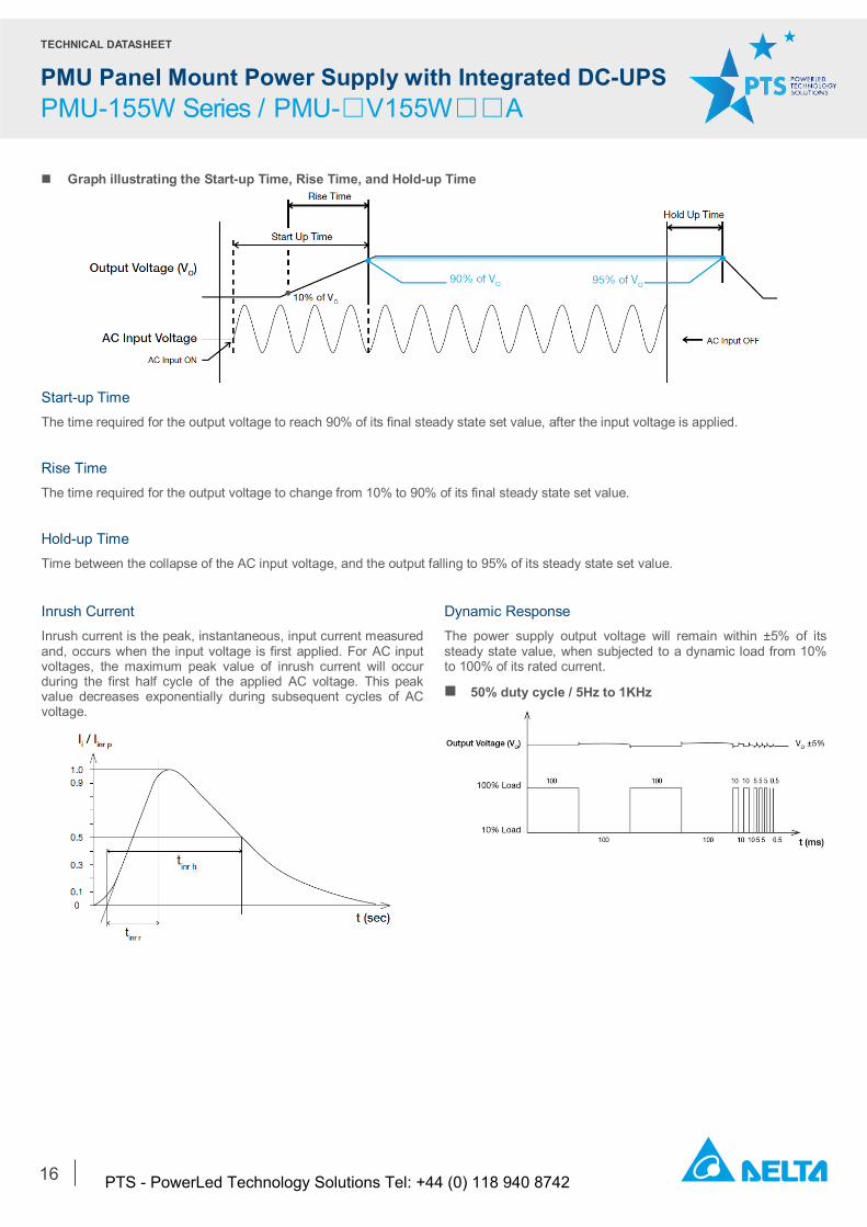
Graph illustrating the Start-up Time, Rise Time, and Hold-up Time
Start-up Time The time required for the output voltage to reach 90% of its final steady state set value, after the input voltage is applied. Rise Time The time required for the output voltage to change from 10% to 90% of its final steady state set value. Hold-up Time Time between the collapse of the AC input voltage, and the output falling to 95% of its steady state set value. Inrush Current Inrush current is the peak, instantaneous, input current measured and, occurs when the input voltage is first applied. For AC input voltages, the maximum peak value of inrush current will occur during the first half cycle of the applied AC voltage. This peak value decreases exponentially during subsequent cycles of AC voltage.
Dynamic Response The power supply output voltage will remain within ±5% of its steady state value, when subjected to a dynamic load from 10% to 100% of its rated current.
50% duty cycle / 5Hz to 1KHz
PTS - PowerLed Technology Solutions Tel: +44 (0) 118 940 8742
TECHNICAL DATASHEET
PMU Panel Mount Power Supply with Integrated DC-UPS PMU-155W Series / PMU-□V155W□□A
17
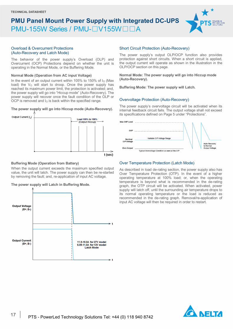
Overload & Overcurrent Protections (Auto-Recovery and Latch Mode) The behavior of the power supply’s Overload (OLP) and Overcurrent (OCP) Protections depend on whether the unit is operating in the Normal Mode, or the Buffering Mode. Normal Mode (Operation from AC input Voltage) In the event of an output current within 105% to 150% of IO (Max load) the VO will start to droop. Once the power supply has reached its maximum power limit, the protection is activated; and, the power supply will go into “Hiccup mode” (Auto-Recovery). The power supply will recover once the fault condition of the OLP or OCP is removed and IO is back within the specified range. The power supply will go into Hiccup mode (Auto-Recovery).
Buffering Mode (Operation from Battery) When the output current exceeds the maximum specified output value, the unit will latch. The power supply can then be re-started by removing the fault; and, re-application of input AC voltage. The power supply will Latch in Buffering Mode.
Short Circuit Protection (Auto-Recovery) The power supply’s output OLP/OCP function also provides protection against short circuits. When a short circuit is applied, the output current will operate as shown in the illustration in the OLP/OCP section on this page. Normal Mode: The power supply will go into Hiccup mode (Auto-Recovery). Buffering Mode: The power supply will Latch. Overvoltage Protection (Auto-Recovery) The power supply’s overvoltage circuit will be activated when its internal feedback circuit fails. The output voltage shall not exceed its specifications defined on Page 5 under “Protections”.
Over Temperature Protection (Latch Mode) As described in load de-rating section, the power supply also has Over Temperature Protection (OTP). In the event of a higher operating temperature at 100% load; or, when the operating temperature is beyond what is recommended in the de-rating graph, the OTP circuit will be activated. When activated, power supply will latch off, until the surrounding air temperature drops to its normal operating temperature or the load is reduced as recommended in the de-rating graph. Removal/re-application of input AC voltage will then be required in order to restart.
PTS - PowerLed Technology Solutions Tel: +44 (0) 118 940 8742
TECHNICAL DATASHEET
PMU Panel Mount Power Supply with Integrated DC-UPS PMU-155W Series / PMU-□V155W□□A
18
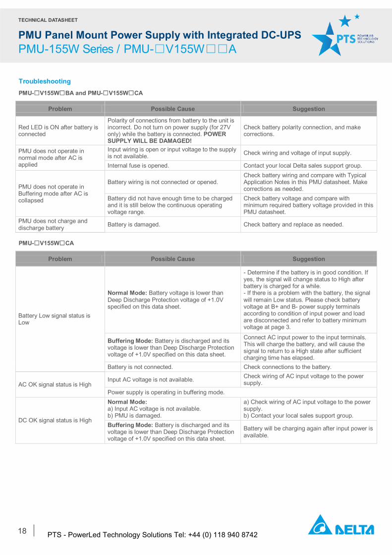
Troubleshooting PMU-☐V155W☐BA and PMU-☐V155W☐CA
Problem Possible Cause Suggestion
Red LED is ON after battery is connected
Polarity of connections from battery to the unit is incorrect. Do not turn on power supply (for 27V only) while the battery is connected. POWER SUPPLY WILL BE DAMAGED!
Check battery polarity connection, and make corrections.
PMU does not operate in normal mode after AC is applied
Input wiring is open or input voltage to the supply is not available. Check wiring and voltage of input supply.
Internal fuse is opened. Contact your local Delta sales support group.
PMU does not operate in Buffering mode after AC is collapsed
Battery wiring is not connected or opened. Check battery wiring and compare with Typical Application Notes in this PMU datasheet. Make corrections as needed.
Battery did not have enough time to be charged and it is still below the continuous operating voltage range.
Check battery voltage and compare with minimum required battery voltage provided in this PMU datasheet.
PMU does not charge and discharge battery Battery is damaged. Check battery and replace as needed.
PMU-☐V155W☐CA
Problem Possible Cause Suggestion
Battery Low signal status is Low
Normal Mode: Battery voltage is lower than Deep Discharge Protection voltage of +1.0V specified on this data sheet.
- Determine if the battery is in good condition. If yes, the signal will change status to High after battery is charged for a while. - If there is a problem with the battery, the signal will remain Low status. Please check battery voltage at B+ and B- power supply terminals according to condition of input power and load are disconnected and refer to battery minimum voltage at page 3.
Buffering Mode: Battery is discharged and its voltage is lower than Deep Discharge Protection voltage of +1.0V specified on this data sheet.
Connect AC input power to the input terminals. This will charge the battery, and will cause the signal to return to a High state after sufficient charging time has elapsed.
Battery is not connected. Check connections to the battery.
AC OK signal status is High Input AC voltage is not available. Check wiring of AC input voltage to the power
supply. Power supply is operating in buffering mode.
DC OK signal status is High
Normal Mode: a) Input AC voltage is not available. b) PMU is damaged.
a) Check wiring of AC input voltage to the power supply. b) Contact your local sales support group.
Buffering Mode: Battery is discharged and its voltage is lower than Deep Discharge Protection voltage of +1.0V specified on this data sheet.
Battery will be charging again after input power is available.
PTS - PowerLed Technology Solutions Tel: +44 (0) 118 940 8742
TECHNICAL DATASHEET
PMU Panel Mount Power Supply with Integrated DC-UPS PMU-155W Series / PMU-□V155W□□A
19
Others
Delta RoHS Compliant
Restriction of the usage of hazardous substances
The European directive 2011/65/EU limits the maximum impurity level of homogeneous materials such as lead, mercury, cadmium, chrome, polybrominated flame retardants PBB and PBDE for the use in electrical and electronic equipment. RoHS is the abbreviation for “Restriction of the use of certain hazardous substances in electrical and electronic equipment”.
This product conforms to this standard. PFC – Norm EN 61000-3-2
Line Current Harmonic content
Typically, the input current waveform is not sinusoidal due to the periodic peak charging of the input capacitor. In industrial environments, compliance with EN 61000-3-2 is only necessary under special conditions. Complying to this standard can have some technical drawbacks, such as lower efficiency; and, can also result in higher product cost. Frequently, the user does not profit from compliance to this standard; therefore, it is important to know whether it is mandatory to meet this standard for a specific application.
PTS - PowerLed Technology Solutions Tel: +44 (0) 118 940 8742