Platelet Incubator Model 301650 Operating Instructions
45
N2400359 - Rev. 1 – 01/22/2016 1 Platelet Incubator Model 301650 Operating Instructions Model Number _ 301650_____ Serial Number ______________
Transcript of Platelet Incubator Model 301650 Operating Instructions

N2400359 - Rev. 1 – 01/22/2016 1
Platelet Incubator Model 301650
Operating Instructions
Model Number _ 301650_____
Serial Number ______________

N2400359 - Rev. 1 – 01/22/2016 2
Contents
1. SAFETY .....................................................................................................................................................4
1.1. EMF INTERFERENCE ......................................................................................................................5 1.2 DEFAULT PASSCODE .............................................................................................................................5
2. PRODUCT INFORMATION ..................................................................................................................6
2.1 INTRODUCTION ......................................................................................................................................6 2.2 INDICATIONS FOR USE OF THE BOEKEL PLATELET INCUBATOR ................................................................6
3. ASSEMBLY ..........................................................................................................................................6
3.1 UNPACKING ...........................................................................................................................................6 3.2 INSTALLATION .......................................................................................................................................7
4. SYSTEM OVERVIEW ...........................................................................................................................8
4.1 MAJOR COMPONENTS ............................................................................................................................8 4.1 MAJOR COMPONENTS (CONTINUED) .......................................................................................................9
5. OPERATION ...................................................................................................................................... 10
5.1 CONTROLS AND DISPLAYS – HOME SCREEN ........................................................................................ 10 5.2 THE INVENTORY MANAGEMENT SYSTEM .............................................................................................. 11 5.3 DATA ACQUISITION SYSTEM ................................................................................................................ 13 – VIEWING THE TEMPERATURE LOG .......................................................................................................... 15 – ON BOARD PRINTING SYSTEM................................................................................................................ 16 – REPLACING PRINTER PAPER .................................................................................................................. 16 – PRINTER NOTIFICATIONS ........................................................................................................................ 16 5.4 BATTERY BACKUP .............................................................................................................................. 17 5.5 SETUP MENU ...................................................................................................................................... 18 – INVENTORY TIMER SETUP ...................................................................................................................... 20 – INVENTORY TIMER SETUP (CONTINUED) .................................................................................................. 21 5.6 CALIBRATION ..................................................................................................................................... 23 – LOW POINT CALIBRATION ...................................................................................................................... 23 – HIGH POINT CALIBRATION...................................................................................................................... 24 5.7 HIGH/LOW TEMPERATURE ALARM TEST .............................................................................................. 26 5.8 ALARMS ............................................................................................................................................. 30 – AGITATION ALARM ................................................................................................................................ 30 – GENERAL EQUIPMENT ALARM ................................................................................................................ 30 – DOOR ALARM ........................................................................................................................................ 31 – NETWORK ALARM ................................................................................................................................. 31 – HIGH / LOW TEMPERATURE ALARMS ...................................................................................................... 31 – BATTERY ALARM ................................................................................................................................... 32 – EXPIRATION WARNING NOTIFICATION ..................................................................................................... 32 5.9 HELP MENU – ICON DESCRIPTIONS ..................................................................................................... 33 5.9 HELP MENU (CONTINUED) ................................................................................................................... 34 5.9 HELP MENU (CONTINUED) ................................................................................................................... 35 5.9 HELP MENU (CONTINUED) ................................................................................................................... 36 5.9 HELP MENU (CONTINUED) ................................................................................................................... 37 5.9 HELP MENU (CONTINUED) ................................................................................................................... 38 5.10 NETWORK CONNECTION ................................................................................................................... 39
6. SPECIFICATIONS & OPERATING CONDITIONS ........................................................................... 41
6.1 DEFAULT SETTINGS ............................................................................................................................ 41
7. MAINTENANCE AND SERVICE ....................................................................................................... 42
7.1. CLEANING ................................................................................................................................... 42 7.1.1. Cleaning Spilled Platelets .............................................................................................. 42
7.2. CALIBRATION .............................................................................................................................. 42 7.3. REPLACEMENT OF FUSES ............................................................................................................ 43

N2400359 - Rev. 1 – 01/22/2016 3
8. TROUBLESHOOTING ...................................................................................................................... 44
9. WARRANTY AND SERVICE ............................................................................................................ 45
9.1. WARRANTY ................................................................................................................................. 45 9.2. SERVICE ..................................................................................................................................... 45
N2400359 - Rev. 1 – 01/22/2016 4
1. Safety
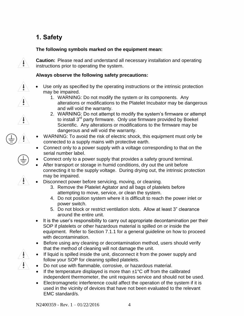
The following symbols marked on the equipment mean: Caution: Please read and understand all necessary installation and operating instructions prior to operating the system.
Always observe the following safety precautions:
Use only as specified by the operating instructions or the intrinsic protection may be impaired.
1. WARNING: Do not modify the system or its components. Any alterations or modifications to the Platelet Incubator may be dangerous and will void the warranty.
2. WARNING: Do not attempt to modify the system’s firmware or attempt to install 3rd party firmware. Only use firmware provided by Boekel Scientific. Any alterations or modifications to the firmware may be dangerous and will void the warranty.
WARNING: To avoid the risk of electric shock, this equipment must only be connected to a supply mains with protective earth.
Connect only to a power supply with a voltage corresponding to that on the serial number label.
Connect only to a power supply that provides a safety ground terminal.
After transport or storage in humid conditions, dry out the unit before connecting it to the supply voltage. During drying out, the intrinsic protection may be impaired.
Disconnect power before servicing, moving, or cleaning. 3. Remove the Platelet Agitator and all bags of platelets before
attempting to move, service, or clean the system. 4. Do not position system where it is difficult to reach the power inlet or
power switch. 5. Do not block or restrict ventilation slots. Allow at least 3” clearance
around the entire unit.
It is the user’s responsibility to carry out appropriate decontamination per their SOP if platelets or other hazardous material is spilled on or inside the equipment. Refer to Section 7.1.1 for a general guideline on how to proceed with decontamination.
Before using any cleaning or decontamination method, users should verify that the method of cleaning will not damage the unit.
If liquid is spilled inside the unit, disconnect it from the power supply and follow your SOP for cleaning spilled platelets.
Do not use with flammable, corrosive, or hazardous material.
If the temperature displayed is more than ±1°C off from the calibrated independent thermometer, the unit requires service and should not be used.
Electromagnetic interference could affect the operation of the system if it is used in the vicinity of devices that have not been evaluated to the relevant EMC standard/s.
N2400359 - Rev. 1 – 01/22/2016 5
1.1. EMF Interference
This system may cause interference to radio and television reception or to equipment sensitive to electromagnetic fields. When installed properly, the system has been designed to minimize this effect. However, there is no guarantee that electromagnetic interference will not be caused by the system. If the system does cause interference to radio, television, or other equipment, which can be determined by turning the instrument off and on, the user may attempt to correct the interference by one or more of the following measures:
Increase the distance between the system and the radio/TV receiver.
Connect the system to an outlet on an electrical circuit different from that which the radio/TV receiver is connected.
If this system is used near an intense electromagnetic source, interference noise may cause an adverse effect on the system performance or functionality. The system is designed to minimize possible interference from external electromagnetic fields; however, there is no guarantee that external electromagnetic fields will not have an effect on this instrument. If the system does incur electromagnetic interference, which can be determined by turning on and off possible source(s) of electromagnetic interference nearby, the user may attempt to correct the interference by one or more of the following measures:
Reorient the instrument.
Increase separation between the instrument and possible source(s) of electromagnetic interference.
Connect the instrument to an outlet on a different electrical circuit from the possible source(s) of electromagnetic interference.
Check that any other device connected to the system is not affected by electromagnetic interference.
1.2 Default Passcode
To change advanced settings of the incubator, a passcode is required. The
passcode can be changed via the setup menu.
The default passcode is: 1234
N2400359 - Rev. 1 – 01/22/2016 6
2. Product Information
2.1 Introduction
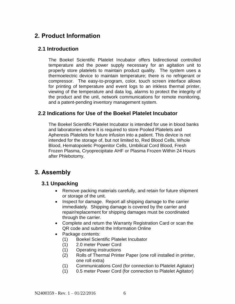
The Boekel Scientific Platelet Incubator offers bidirectional controlled temperature and the power supply necessary for an agitation unit to properly store platelets to maintain product quality. The system uses a thermoelectric device to maintain temperature; there is no refrigerant or compressor. The easy-to-program, color, touch screen interface allows for printing of temperature and event logs to an inkless thermal printer, viewing of the temperature and data log, alarms to protect the integrity of the product and the unit, network communications for remote monitoring, and a patent-pending inventory management system.
2.2 Indications for Use of the Boekel Platelet Incubator The Boekel Scientific Platelet Incubator is intended for use in blood banks and laboratories where it is required to store Pooled Platelets and Apheresis Platelets for future infusion into a patient. This device is not intended for the storage of, but not limited to, Red Blood Cells, Whole Blood, Hematopoietic Progenitor Cells, Umbilical Cord Blood, Fresh Frozen Plasma, Cryoprecipitate AHF or Plasma Frozen Within 24 Hours after Phlebotomy.
3. Assembly
3.1 Unpacking
Remove packing materials carefully, and retain for future shipment or storage of the unit.
Inspect for damage. Report all shipping damage to the carrier immediately. Shipping damage is covered by the carrier and repair/replacement for shipping damages must be coordinated through the carrier.
Complete and return the Warranty Registration Card or scan the QR code and submit the Information Online
Package contents: (1) Boekel Scientific Platelet Incubator (1) 2.0 meter Power Cord (1) Operating instructions (2) Rolls of Thermal Printer Paper (one roll installed in printer,
one roll extra) (1) Communications Cord (for connection to Platelet Agitator) (1) 0.5 meter Power Cord (for connection to Platelet Agitator)
N2400359 - Rev. 1 – 01/22/2016 7
3.2 Installation
1. Place the Platelet Incubator on a flat and stable surface, making
certain the sides and back have at least 3 inches of clearance for proper airflow.
2. Fit the power line cord into the IEC power socket on the left side of
the unit and plug the power cord into a properly grounded outlet.
3. Power on the unit using the switch above the power cord inlet
4. Upon startup, a temperature alarm may sound. This alarm can be silenced by pressing the alarm icon and pressing the green confirmation check mark. The alarm will resolve when the incubator nears target temperature. This is normal.
5. Once the system boots up, it will immediately begin controlling
temperature to the default setting of 22˚C. No operator intervention is required for this.
6. Once the system is verified to be working, proceed with installing
the Platelet Agitator inside the Platelet Incubator.
7. Install the power cord and the communications cord on the Platelet Agitator. The 0.5 meter power cord supplied with the incubator can be used in place of the 2.0 meter power cord supplied with the Platelet Agitator when plugging the Platelet Agitator into the Platelet Incubator.
8. If space allows, open the Platelet Incubator door and place the
Platelet Agitator in front of the door opening. Connect the Platelet Agitator power cord and communications cord to the corresponding ports on the rear wall of the Incubator. After the connections are made, place the Platelet Agitator inside the Incubator, routing the cords as necessary to ensure they are not underneath the Platelet Agitator.
Otherwise, the Platelet Agitator can be placed inside the Incubator prior to connecting the power cord and communications cord to the corresponding ports on the rear wall of the Incubator. Removing the shelves from the Agitator will make it easier to access these cords and ports by permitting a hand to reach through the Agitator housing. To remove the shelves, start with the top shelf and pull it out until it reaches its stop. While pulling the quick-release pins from both sides of the shelf, remove the shelf from the enclosure. Repeat
N2400359 - Rev. 1 – 01/22/2016 8
these steps for the remaining shelves. Reverse these steps to reinstall the shelves.
9. Make sure the Platelet Agitator feet rest in the four dimples on the
base of the incubator chamber. This will ensure proper equipment placement.
4. System Overview
4.1 Major Components
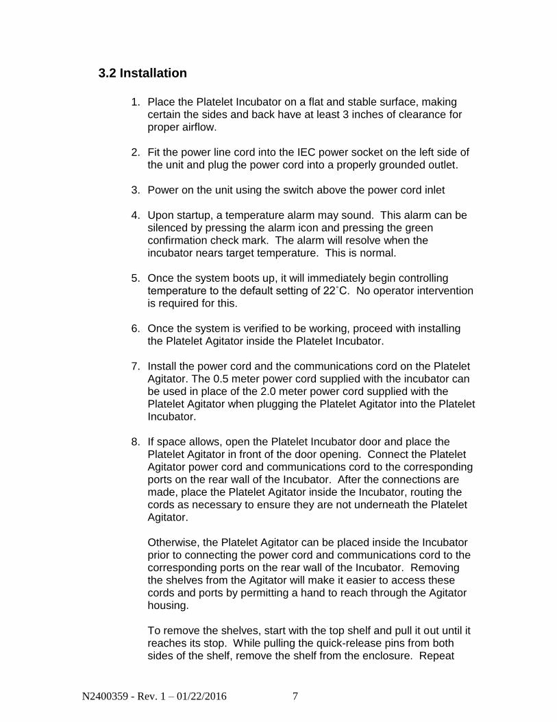
1. On Board Thermal Printer – Prints temperature log for selected timeframe.
2. User Interface – Color touch screen display. 3. USB port – Used to download system data and upload new firmware,
if required. 4. Lifting Handles – For lifting or moving unit. Two people required. 5. Door Handle – Used to open the incubator chamber to access the
agitator. 6. Agitator Power Switch - Turns the agitator on/off. 7. Platelet Agitator – Used for agitating platelets.
1 2 3
4
5
6 7
N2400359 - Rev. 1 – 01/22/2016 9
4.1 Major Components (continued)
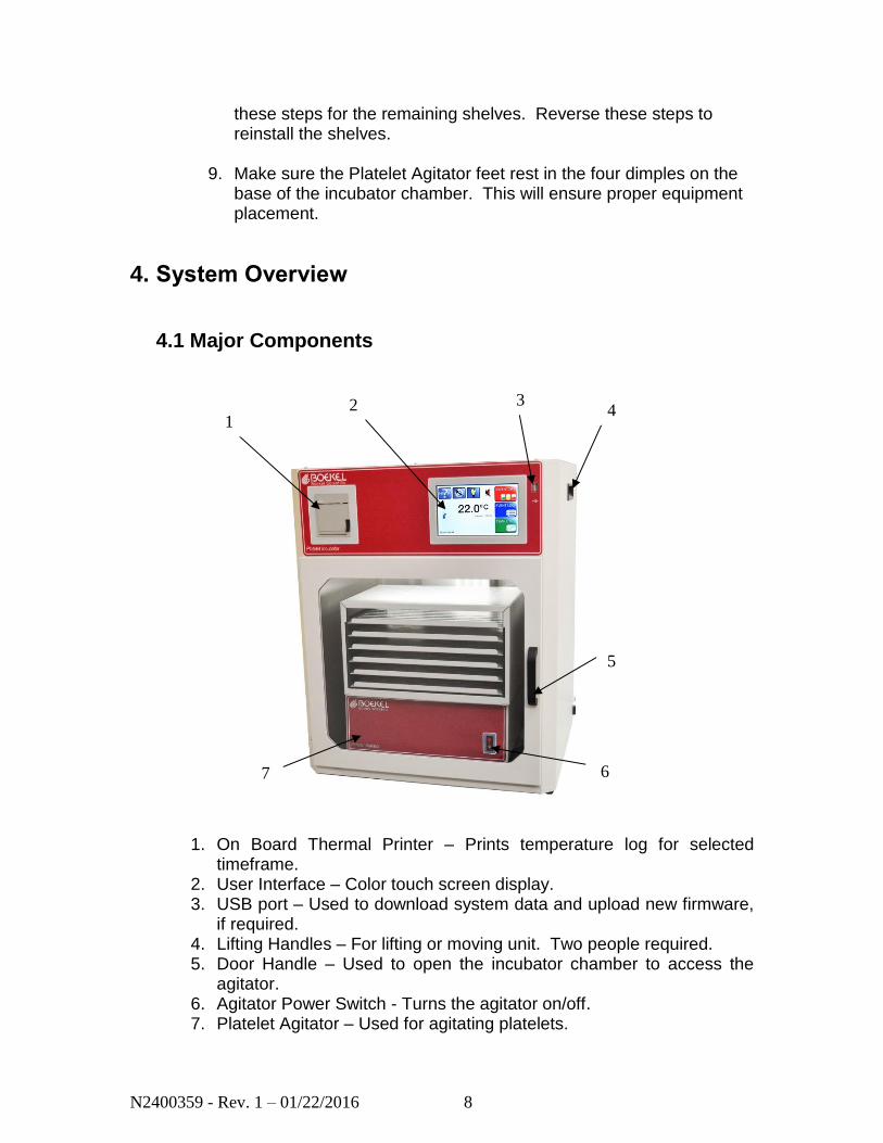
8. Power Connection/Power Button/Fuse housing – Used for powering and turning the power on/off.
9. Heating / Cooling Device – Heats and cools the chamber. 10. Power Outlet – For connecting power to platelet agitator and starting/
stopping of the unit. 11. Communications Connection – Connects to agitator for alarms. 12. Agitator Fuse Housing – Electrical protection for the agitator.
9 10
11
8
12
N2400359 - Rev. 1 – 01/22/2016 10
5. Operation
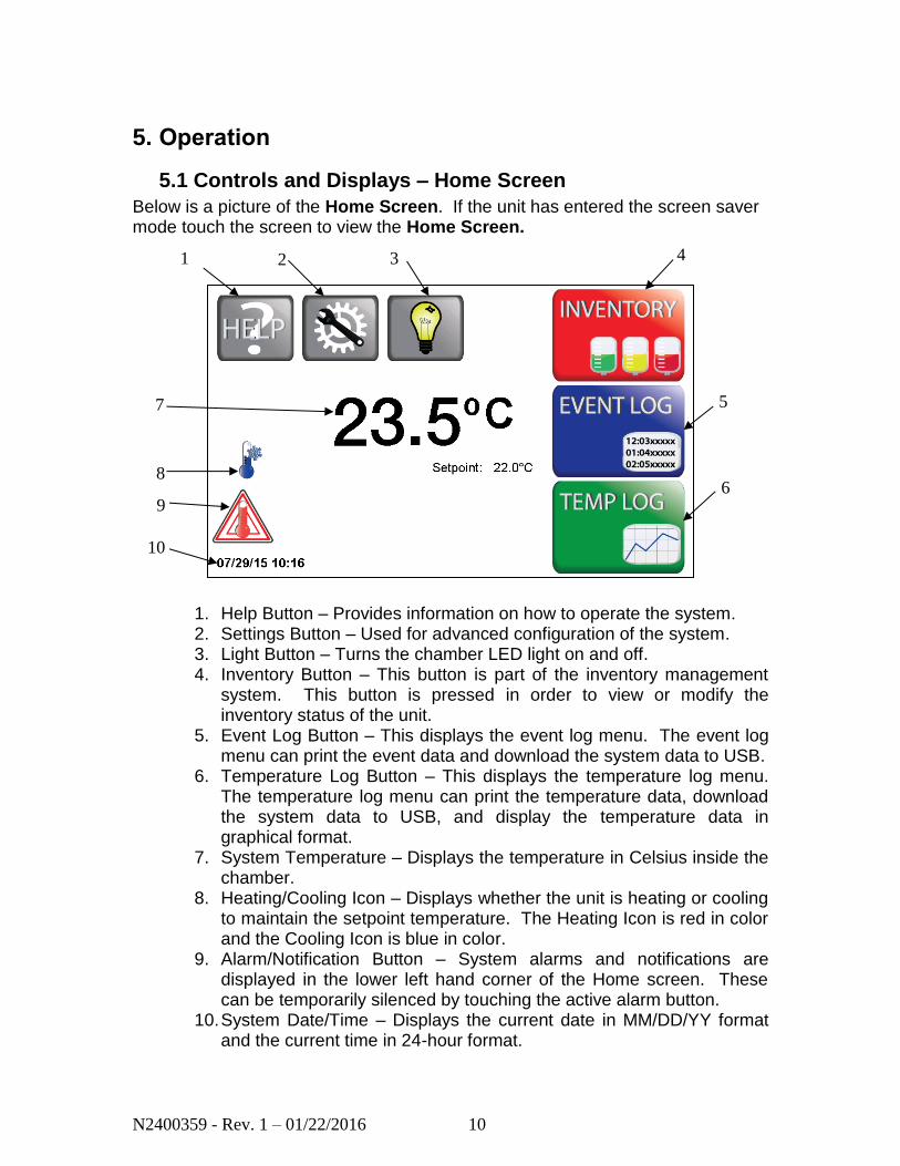
5.1 Controls and Displays – Home Screen
Below is a picture of the Home Screen. If the unit has entered the screen saver mode touch the screen to view the Home Screen.
1. Help Button – Provides information on how to operate the system. 2. Settings Button – Used for advanced configuration of the system. 3. Light Button – Turns the chamber LED light on and off. 4. Inventory Button – This button is part of the inventory management
system. This button is pressed in order to view or modify the inventory status of the unit.
5. Event Log Button – This displays the event log menu. The event log menu can print the event data and download the system data to USB.
6. Temperature Log Button – This displays the temperature log menu. The temperature log menu can print the temperature data, download the system data to USB, and display the temperature data in graphical format.
7. System Temperature – Displays the temperature in Celsius inside the chamber.
8. Heating/Cooling Icon – Displays whether the unit is heating or cooling to maintain the setpoint temperature. The Heating Icon is red in color and the Cooling Icon is blue in color.
9. Alarm/Notification Button – System alarms and notifications are displayed in the lower left hand corner of the Home screen. These can be temporarily silenced by touching the active alarm button.
10. System Date/Time – Displays the current date in MM/DD/YY format and the current time in 24-hour format.
4 1 2 3
6 9
5 7
8
10
N2400359 - Rev. 1 – 01/22/2016 11
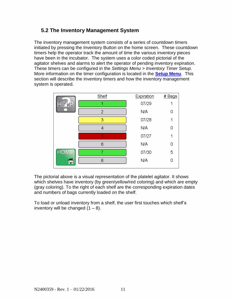
5.2 The Inventory Management System
The inventory management system consists of a series of countdown timers initiated by pressing the Inventory Button on the home screen. These countdown timers help the operator track the amount of time the various inventory pieces have been in the incubator. The system uses a color coded pictorial of the agitator shelves and alarms to alert the operator of pending inventory expiration. These timers can be configured in the Settings Menu > Inventory Timer Setup. More information on the timer configuration is located in the Setup Menu. This section will describe the inventory timers and how the inventory management system is operated.
The pictorial above is a visual representation of the platelet agitator. It shows which shelves have inventory (by green/yellow/red coloring) and which are empty (gray coloring). To the right of each shelf are the corresponding expiration dates and numbers of bags currently loaded on the shelf. To load or unload inventory from a shelf, the user first touches which shelf’s inventory will be changed (1 – 8).
N2400359 - Rev. 1 – 01/22/2016 12
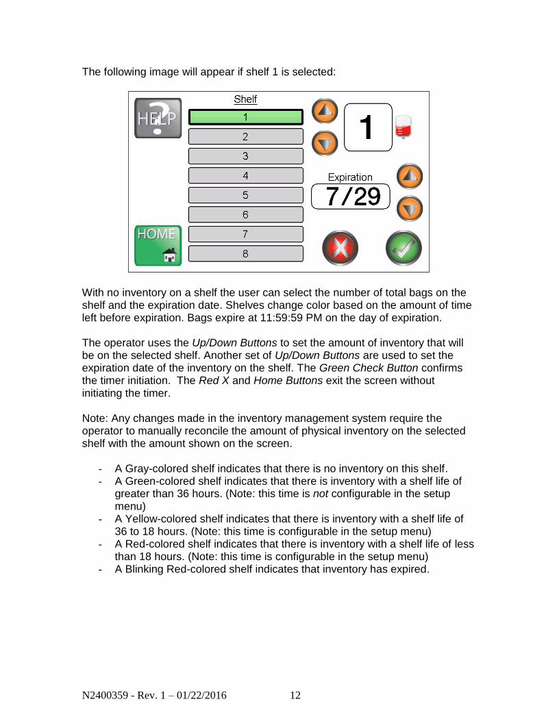
The following image will appear if shelf 1 is selected:
With no inventory on a shelf the user can select the number of total bags on the shelf and the expiration date. Shelves change color based on the amount of time left before expiration. Bags expire at 11:59:59 PM on the day of expiration. The operator uses the Up/Down Buttons to set the amount of inventory that will be on the selected shelf. Another set of Up/Down Buttons are used to set the expiration date of the inventory on the shelf. The Green Check Button confirms the timer initiation. The Red X and Home Buttons exit the screen without initiating the timer. Note: Any changes made in the inventory management system require the operator to manually reconcile the amount of physical inventory on the selected shelf with the amount shown on the screen.
- A Gray-colored shelf indicates that there is no inventory on this shelf. - A Green-colored shelf indicates that there is inventory with a shelf life of
greater than 36 hours. (Note: this time is not configurable in the setup menu)
- A Yellow-colored shelf indicates that there is inventory with a shelf life of 36 to 18 hours. (Note: this time is configurable in the setup menu)
- A Red-colored shelf indicates that there is inventory with a shelf life of less than 18 hours. (Note: this time is configurable in the setup menu)
- A Blinking Red-colored shelf indicates that inventory has expired.
N2400359 - Rev. 1 – 01/22/2016 13
5.3 Data Acquisition System
The Platelet Incubator logs temperature data and system event data to ensure product quality during operation. This data is available in four different ways.
- Screen Saver – The temperature trend graph is displayed as one of the rotating screen savers.
- Print – The system can print the temperature log graph for up to thirty days from the Log Menus.
- Download – The system can download the temperature data and system data for up to thirty days from the Log Menus in .CSV format to a USB drive from the USB port located on the front of the unit.
- System Log Download – From the USB Button in the Settings Menu the system can download to a USB drive all of the data in the internal memory.
N2400359 - Rev. 1 – 01/22/2016 14
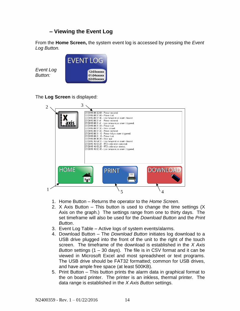
– Viewing the Event Log
From the Home Screen, the system event log is accessed by pressing the Event Log Button. Event Log Button: The Log Screen is displayed:
1. Home Button – Returns the operator to the Home Screen. 2. X Axis Button – This button is used to change the time settings (X
Axis on the graph.) The settings range from one to thirty days. The set timeframe will also be used for the Download Button and the Print Button.
3. Event Log Table – Active logs of system events/alarms. 4. Download Button – The Download Button initiates log download to a
USB drive plugged into the front of the unit to the right of the touch screen. The timeframe of the download is established in the X Axis Button settings (1 – 30 days). The file is in CSV format and it can be viewed in Microsoft Excel and most spreadsheet or text programs. The USB drive should be FAT32 formatted; common for USB drives, and have ample free space (at least 500KB).
5. Print Button – This button prints the alarm data in graphical format to the on board printer. The printer is an inkless, thermal printer. The data range is established in the X Axis Button settings.
2
1
3
4 5

N2400359 - Rev. 1 – 01/22/2016 15
– Viewing the Temperature Log
From the Home Screen, the system temperature log is accessed by pressing the Temp Log Button. Temp Log Button: The Log Screen is displayed:
1. Home Button – Returns the operator to the Home Screen. 2. X Axis Button – This button is used to change the time settings (X
Axis on the graph.) The settings range from one to thirty days. The set timeframe will also be used for the Download Button and the Print Button. The default setting is 7 days.
3. Temperature Log Graph – Active logs of temperature versus time. 4. Download Button – The Download Button initiates log download to a
USB drive plugged into the front of the unit to the right of the touch screen. The timeframe of the download is established in the X Axis Button settings (1 – 30 days). The file is in CSV format and it can be viewed in Microsoft Excel and most spreadsheet or text programs. The USB drive should be FAT32 formatted; common for USB drives, and have ample free space (at least 500KB).
5. Print Button – This button prints the data in graphical format to the on board printer. The printer is an inkless, thermal printer. The data range is established in the X Axis Button settings.
1 4 5
2 3
N2400359 - Rev. 1 – 01/22/2016 16
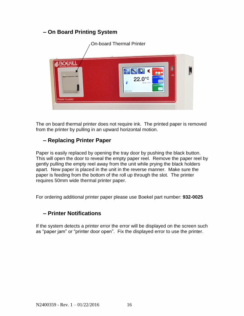
– On Board Printing System
The on board thermal printer does not require ink. The printed paper is removed from the printer by pulling in an upward horizontal motion.
– Replacing Printer Paper
Paper is easily replaced by opening the tray door by pushing the black button. This will open the door to reveal the empty paper reel. Remove the paper reel by gently pulling the empty reel away from the unit while prying the black holders apart. New paper is placed in the unit in the reverse manner. Make sure the paper is feeding from the bottom of the roll up through the slot. The printer requires 50mm wide thermal printer paper. For ordering additional printer paper please use Boekel part number: 932-0025
– Printer Notifications
If the system detects a printer error the error will be displayed on the screen such as “paper jam” or “printer door open”. Fix the displayed error to use the printer.
On-board Thermal Printer

N2400359 - Rev. 1 – 01/22/2016 17
5.4 Battery Backup
If power is lost because of a power failure, or the power switch has been turned off without shutting down the system, the incubator will enter a Battery Backup Mode of operation. In a battery backup situation, the system continues data logging of the temperature probe values only. Temperature control, touchscreen interface, and printer functionality will not be available in Battery Backup Mode. Should power be lost, it is recommended to transfer the platelet inventory to another temperature controlled location as soon as possible. The incubator chamber will get warmer due to residual heat generated by the agitator motor.
N2400359 - Rev. 1 – 01/22/2016 18
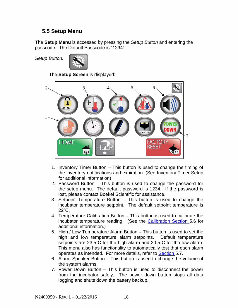
5.5 Setup Menu
The Setup Menu is accessed by pressing the Setup Button and entering the passcode. The Default Passcode is “1234”. Setup Button:
The Setup Screen is displayed:
1. Inventory Timer Button – This button is used to change the timing of
the inventory notifications and expiration. (See Inventory Timer Setup for additional information)
2. Password Button – This button is used to change the password for the setup menu. The default password is 1234. If the password is lost, please contact Boekel Scientific for assistance.
3. Setpoint Temperature Button – This button is used to change the incubator temperature setpoint. The default setpoint temperature is 22˚C.
4. Temperature Calibration Button – This button is used to calibrate the incubator temperature reading. (See the Calibration Section 5.6 for additional information.)
5. High / Low Temperature Alarm Button – This button is used to set the high and low temperature alarm setpoints. Default temperature setpoints are 23.5˚C for the high alarm and 20.5˚C for the low alarm. This menu also has functionality to automatically test that each alarm operates as intended. For more details, refer to Section 5.7.
6. Alarm Speaker Button – This button is used to change the volume of the system alarms.
7. Power Down Button – This button is used to disconnect the power from the incubator safely. The power down button stops all data logging and shuts down the battery backup.
7
2
1
3 4 5 6
N2400359 - Rev. 1 – 01/22/2016 19
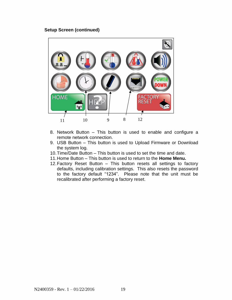
Setup Screen (continued)
8. Network Button – This button is used to enable and configure a
remote network connection. 9. USB Button – This button is used to Upload Firmware or Download
the system log. 10. Time/Date Button – This button is used to set the time and date. 11. Home Button – This button is used to return to the Home Menu. 12. Factory Reset Button – This button resets all settings to factory
defaults, including calibration settings. This also resets the password to the factory default “1234”. Please note that the unit must be recalibrated after performing a factory reset.
8 9 10 11 12
N2400359 - Rev. 1 – 01/22/2016 20
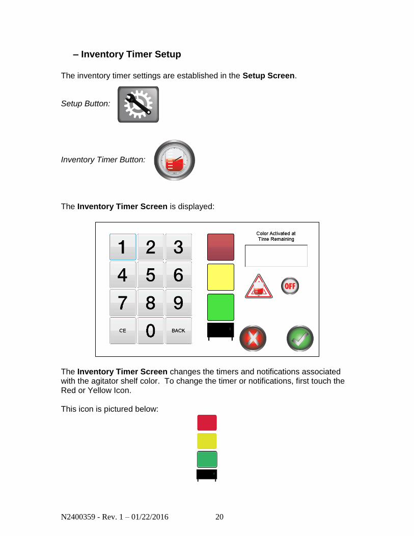
– Inventory Timer Setup
The inventory timer settings are established in the Setup Screen. Setup Button: Inventory Timer Button: The Inventory Timer Screen is displayed:
The Inventory Timer Screen changes the timers and notifications associated with the agitator shelf color. To change the timer or notifications, first touch the Red or Yellow Icon. This icon is pictured below:
N2400359 - Rev. 1 – 01/22/2016 21
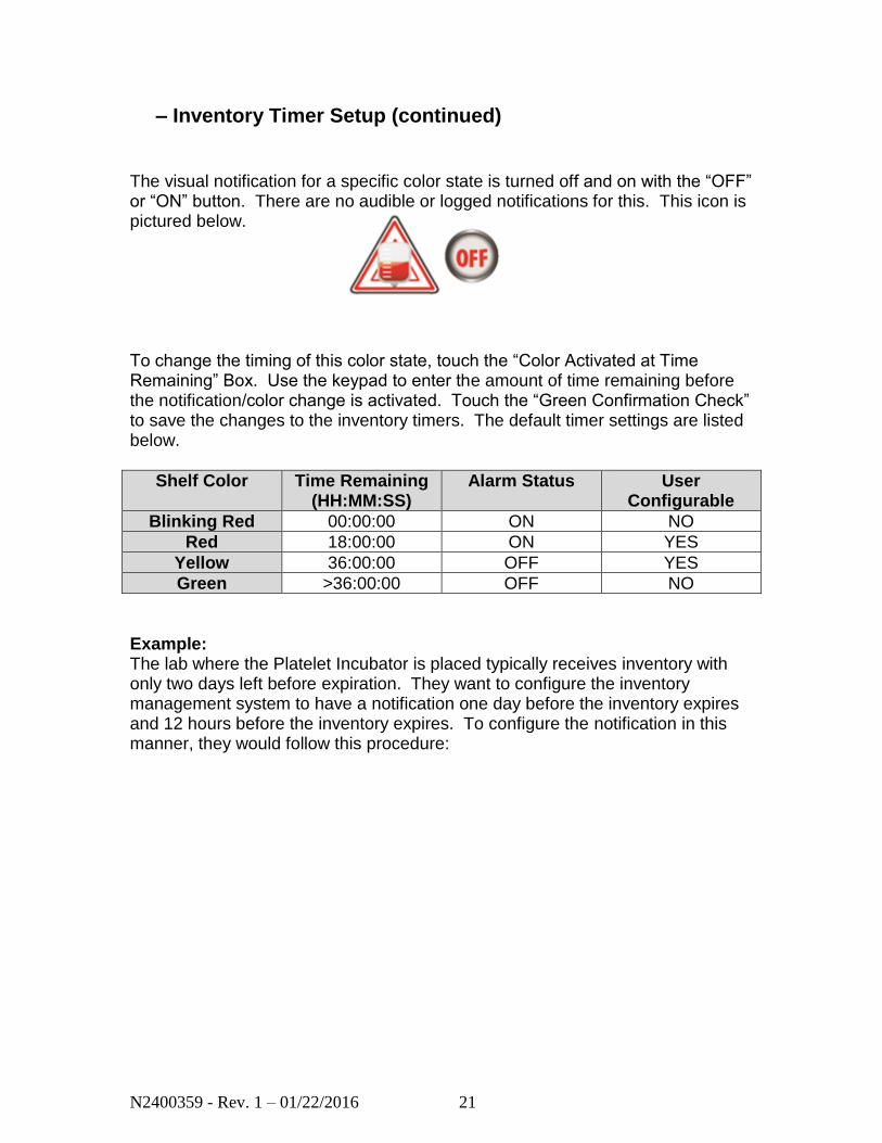
– Inventory Timer Setup (continued)
The visual notification for a specific color state is turned off and on with the “OFF” or “ON” button. There are no audible or logged notifications for this. This icon is pictured below. To change the timing of this color state, touch the “Color Activated at Time Remaining” Box. Use the keypad to enter the amount of time remaining before the notification/color change is activated. Touch the “Green Confirmation Check” to save the changes to the inventory timers. The default timer settings are listed below.
Shelf Color Time Remaining (HH:MM:SS)
Alarm Status User Configurable
Blinking Red 00:00:00 ON NO
Red 18:00:00 ON YES
Yellow 36:00:00 OFF YES
Green >36:00:00 OFF NO
Example: The lab where the Platelet Incubator is placed typically receives inventory with only two days left before expiration. They want to configure the inventory management system to have a notification one day before the inventory expires and 12 hours before the inventory expires. To configure the notification in this manner, they would follow this procedure:
N2400359 - Rev. 1 – 01/22/2016 22
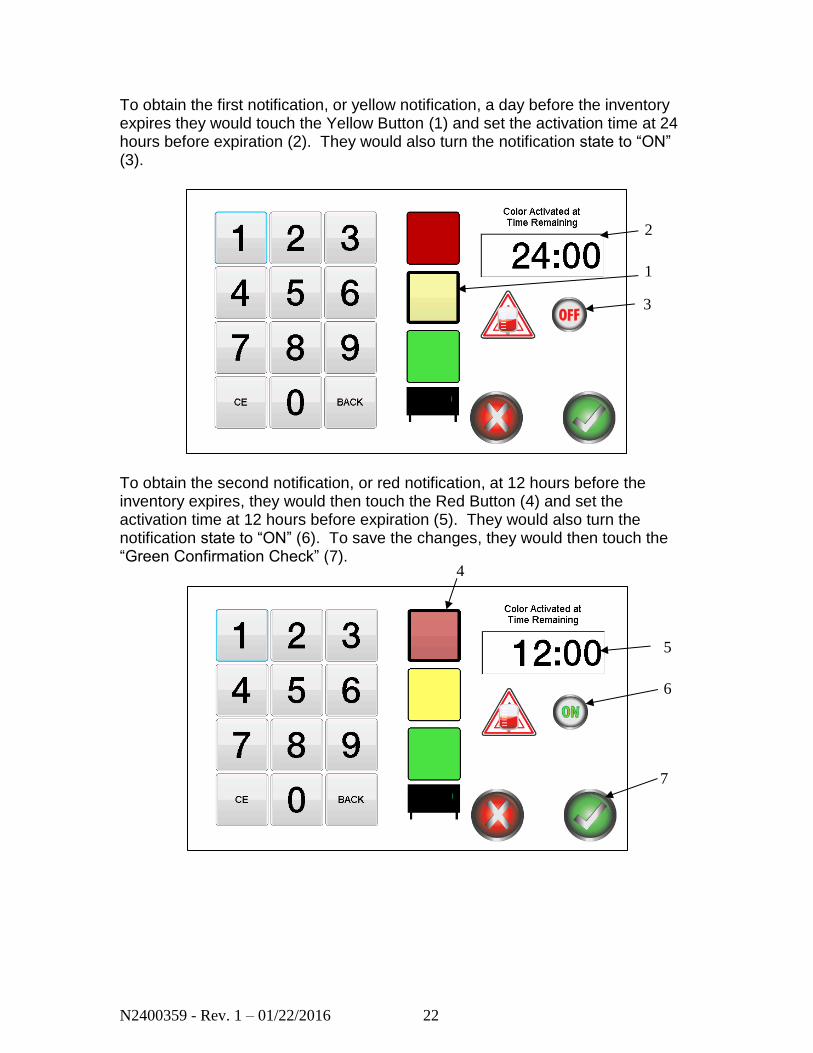
To obtain the first notification, or yellow notification, a day before the inventory expires they would touch the Yellow Button (1) and set the activation time at 24 hours before expiration (2). They would also turn the notification state to “ON” (3).
To obtain the second notification, or red notification, at 12 hours before the inventory expires, they would then touch the Red Button (4) and set the activation time at 12 hours before expiration (5). They would also turn the notification state to “ON” (6). To save the changes, they would then touch the “Green Confirmation Check” (7).
1
2
3
4
5
6
8
7

N2400359 - Rev. 1 – 01/22/2016 23
5.6 Calibration
The platelet incubator has a simple, two point method for calibrating the displayed temperature. Using a precision calibrated temperature device with an accuracy of ±0.2°C or greater is recommended. The calibration device is placed inside the chamber in the center of a middle agitator shelf. During the calibration procedure, the agitator should not contain any inventory or other objects that may impair airflow, and it should be running in the chamber for at least 30 minutes prior to starting the calibration process. The temperature read by the calibration device is used to adjust the displayed reading on the incubator. The sequence will take at least 2 hours and requires the operator to interact with the incubator during the process.
– Low Point Calibration
The calibration sequence is located in the setup menu. Calibration Button:
The Low Point Calibration Screen is displayed:
During the calibration sequence, a timer will start, and the incubator will achieve and stabilize at a low temperature of 20°C. During this time, the “ACTUAL” temperature box will be red and will not be editable.
N2400359 - Rev. 1 – 01/22/2016 24
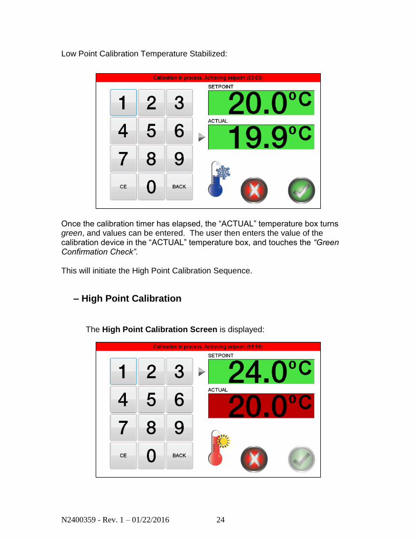
Low Point Calibration Temperature Stabilized:
Once the calibration timer has elapsed, the “ACTUAL” temperature box turns green, and values can be entered. The user then enters the value of the calibration device in the “ACTUAL” temperature box, and touches the “Green Confirmation Check”. This will initiate the High Point Calibration Sequence.
– High Point Calibration
The High Point Calibration Screen is displayed:
N2400359 - Rev. 1 – 01/22/2016 25
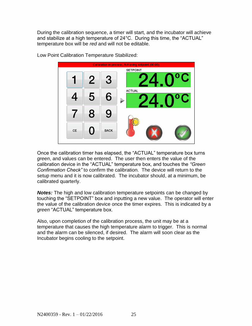
During the calibration sequence, a timer will start, and the incubator will achieve and stabilize at a high temperature of 24°C. During this time, the “ACTUAL” temperature box will be red and will not be editable. Low Point Calibration Temperature Stabilized:
Once the calibration timer has elapsed, the “ACTUAL” temperature box turns green, and values can be entered. The user then enters the value of the calibration device in the “ACTUAL” temperature box, and touches the “Green Confirmation Check” to confirm the calibration. The device will return to the setup menu and it is now calibrated. The incubator should, at a minimum, be calibrated quarterly. Notes: The high and low calibration temperature setpoints can be changed by touching the “SETPOINT” box and inputting a new value. The operator will enter the value of the calibration device once the timer expires. This is indicated by a green “ACTUAL” temperature box. Also, upon completion of the calibration process, the unit may be at a temperature that causes the high temperature alarm to trigger. This is normal and the alarm can be silenced, if desired. The alarm will soon clear as the Incubator begins cooling to the setpoint.
N2400359 - Rev. 1 – 01/22/2016 26
5.7 High/Low Temperature Alarm Test
Many SOPs require the High and Low Temperature Alarms to be tested periodically to ensure they operate as intended. The Boekel Platelet Incubator provides a fully automated test for each alarm. From the Setup Menu, these tests can be accessed through the High/Low Temperature Alarm Button. Before starting, it is recommended to remove all inventory from the Agitator shelves and store them temporarily in another suitable location. During this test, the temperature of the Incubator chamber may exceed AABB recommended guidelines for proper platelet storage. It is recommended that these tests be performed with the Agitator installed and operating in the Incubator chamber. If it is preferred to run the test with the Agitator removed or turned off, be aware that an Agitation Alarm will be triggered. This alarm can be silenced if desired. To test the High Temperature Alarm:
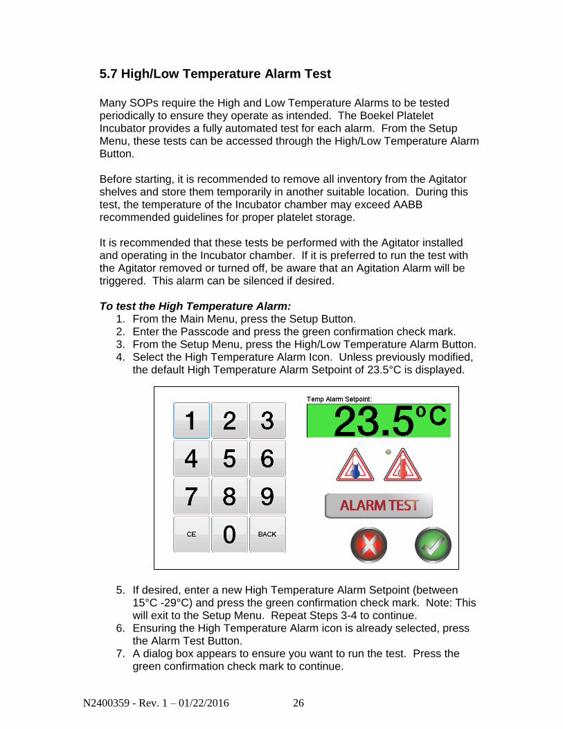
1. From the Main Menu, press the Setup Button. 2. Enter the Passcode and press the green confirmation check mark. 3. From the Setup Menu, press the High/Low Temperature Alarm Button. 4. Select the High Temperature Alarm Icon. Unless previously modified,
the default High Temperature Alarm Setpoint of 23.5°C is displayed.
5. If desired, enter a new High Temperature Alarm Setpoint (between
15°C -29°C) and press the green confirmation check mark. Note: This will exit to the Setup Menu. Repeat Steps 3-4 to continue.
6. Ensuring the High Temperature Alarm icon is already selected, press the Alarm Test Button.
7. A dialog box appears to ensure you want to run the test. Press the green confirmation check mark to continue.
N2400359 - Rev. 1 – 01/22/2016 27
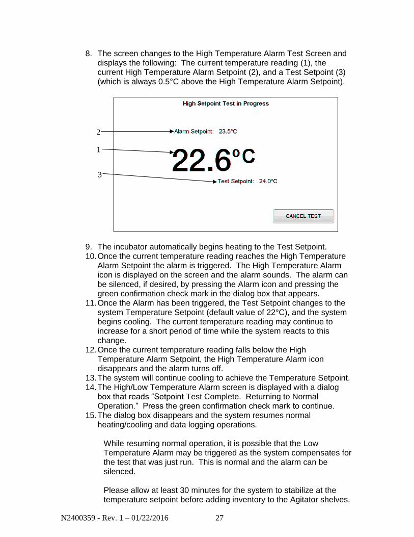
8. The screen changes to the High Temperature Alarm Test Screen and displays the following: The current temperature reading (1), the current High Temperature Alarm Setpoint (2), and a Test Setpoint (3) (which is always 0.5°C above the High Temperature Alarm Setpoint).
9. The incubator automatically begins heating to the Test Setpoint. 10. Once the current temperature reading reaches the High Temperature
Alarm Setpoint the alarm is triggered. The High Temperature Alarm icon is displayed on the screen and the alarm sounds. The alarm can be silenced, if desired, by pressing the Alarm icon and pressing the green confirmation check mark in the dialog box that appears.
11. Once the Alarm has been triggered, the Test Setpoint changes to the system Temperature Setpoint (default value of 22°C), and the system begins cooling. The current temperature reading may continue to increase for a short period of time while the system reacts to this change.
12. Once the current temperature reading falls below the High Temperature Alarm Setpoint, the High Temperature Alarm icon disappears and the alarm turns off.
13. The system will continue cooling to achieve the Temperature Setpoint. 14. The High/Low Temperature Alarm screen is displayed with a dialog
box that reads “Setpoint Test Complete. Returning to Normal Operation.” Press the green confirmation check mark to continue.
15. The dialog box disappears and the system resumes normal heating/cooling and data logging operations.
While resuming normal operation, it is possible that the Low Temperature Alarm may be triggered as the system compensates for the test that was just run. This is normal and the alarm can be silenced. Please allow at least 30 minutes for the system to stabilize at the temperature setpoint before adding inventory to the Agitator shelves.
1
2
3
N2400359 - Rev. 1 – 01/22/2016 28
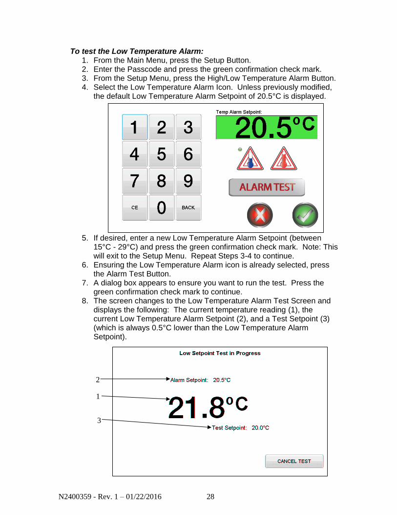
To test the Low Temperature Alarm: 1. From the Main Menu, press the Setup Button. 2. Enter the Passcode and press the green confirmation check mark. 3. From the Setup Menu, press the High/Low Temperature Alarm Button. 4. Select the Low Temperature Alarm Icon. Unless previously modified,
the default Low Temperature Alarm Setpoint of 20.5°C is displayed.
5. If desired, enter a new Low Temperature Alarm Setpoint (between 15°C - 29°C) and press the green confirmation check mark. Note: This will exit to the Setup Menu. Repeat Steps 3-4 to continue.
6. Ensuring the Low Temperature Alarm icon is already selected, press the Alarm Test Button.
7. A dialog box appears to ensure you want to run the test. Press the green confirmation check mark to continue.
8. The screen changes to the Low Temperature Alarm Test Screen and displays the following: The current temperature reading (1), the current Low Temperature Alarm Setpoint (2), and a Test Setpoint (3) (which is always 0.5°C lower than the Low Temperature Alarm Setpoint).
1
2
3
N2400359 - Rev. 1 – 01/22/2016 29
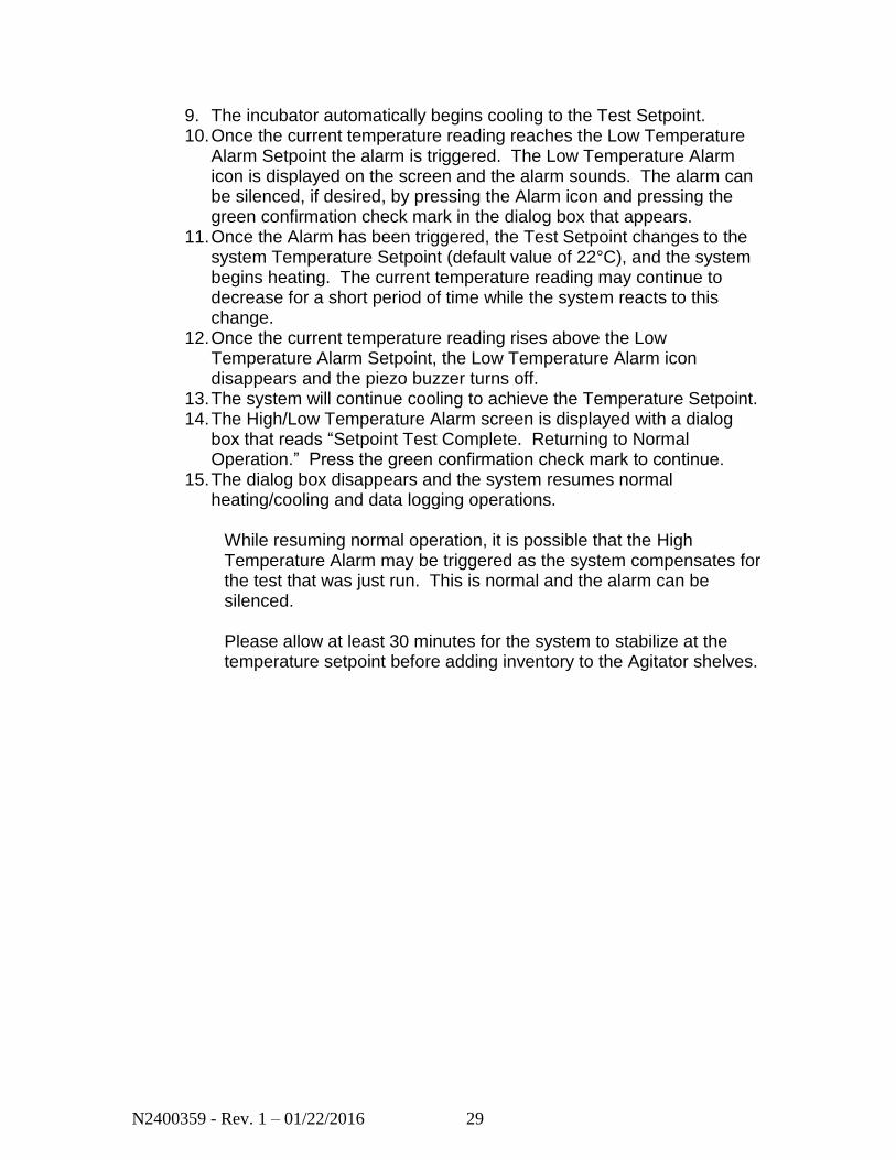
9. The incubator automatically begins cooling to the Test Setpoint. 10. Once the current temperature reading reaches the Low Temperature
Alarm Setpoint the alarm is triggered. The Low Temperature Alarm icon is displayed on the screen and the alarm sounds. The alarm can be silenced, if desired, by pressing the Alarm icon and pressing the green confirmation check mark in the dialog box that appears.
11. Once the Alarm has been triggered, the Test Setpoint changes to the system Temperature Setpoint (default value of 22°C), and the system begins heating. The current temperature reading may continue to decrease for a short period of time while the system reacts to this change.
12. Once the current temperature reading rises above the Low Temperature Alarm Setpoint, the Low Temperature Alarm icon disappears and the piezo buzzer turns off.
13. The system will continue cooling to achieve the Temperature Setpoint. 14. The High/Low Temperature Alarm screen is displayed with a dialog
box that reads “Setpoint Test Complete. Returning to Normal Operation.” Press the green confirmation check mark to continue.
15. The dialog box disappears and the system resumes normal heating/cooling and data logging operations.
While resuming normal operation, it is possible that the High Temperature Alarm may be triggered as the system compensates for the test that was just run. This is normal and the alarm can be silenced. Please allow at least 30 minutes for the system to stabilize at the temperature setpoint before adding inventory to the Agitator shelves.
N2400359 - Rev. 1 – 01/22/2016 30
5.8 Alarms
The platelet incubator has a variety of alarms and notifications to protect the product quality and the system itself. These are listed below. All audible alarms can be silenced by pressing the alarm icon but will reactivate in five minutes if the alarm condition is not fixed/cleared.
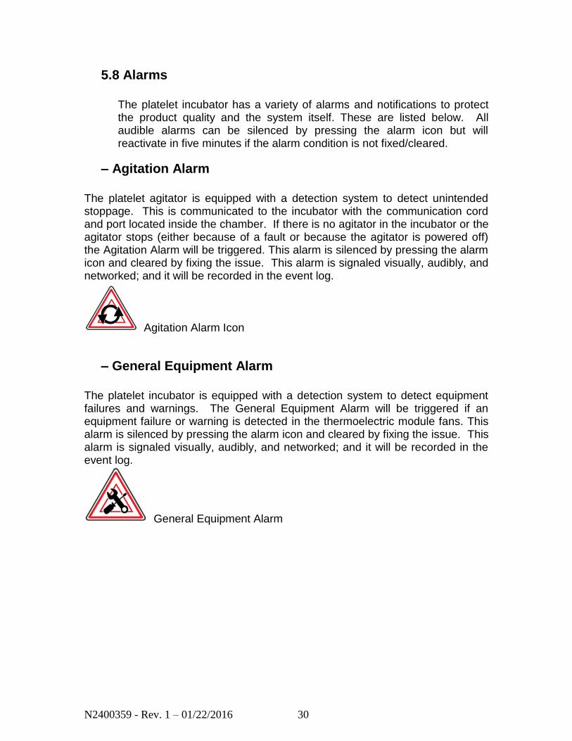
– Agitation Alarm
The platelet agitator is equipped with a detection system to detect unintended stoppage. This is communicated to the incubator with the communication cord and port located inside the chamber. If there is no agitator in the incubator or the agitator stops (either because of a fault or because the agitator is powered off) the Agitation Alarm will be triggered. This alarm is silenced by pressing the alarm icon and cleared by fixing the issue. This alarm is signaled visually, audibly, and networked; and it will be recorded in the event log.
Agitation Alarm Icon
– General Equipment Alarm
The platelet incubator is equipped with a detection system to detect equipment failures and warnings. The General Equipment Alarm will be triggered if an equipment failure or warning is detected in the thermoelectric module fans. This alarm is silenced by pressing the alarm icon and cleared by fixing the issue. This alarm is signaled visually, audibly, and networked; and it will be recorded in the event log.
General Equipment Alarm

N2400359 - Rev. 1 – 01/22/2016 31
– Door Alarm
The platelet incubator is equipped with a door alarm. If the incubator door is open for an extended amount of time (greater than 2 minutes) the door alarm will be triggered. This alarm is silenced by pressing the alarm icon and cleared by closing the door. This alarm is signaled visually, audibly, and networked; and it will be recorded in the event log.
Door Alarm
– Network Alarm
The platelet incubator is equipped with a network alarm. If the incubator is connected to a central monitoring system and has an issue maintaining a connection to the remote network, the network alarm will be triggered. This alarm is silenced by pressing the alarm icon and cleared by re-establishing a connection. This alarm is signaled visually, audibly, and networked (if using the relay connection); and it will be recorded in the event log.
Network Alarm
– High / Low Temperature Alarms
The platelet incubator is equipped with high and low temperature alarms. These alarm setpoints are configurable in the Setup Menu. These alarms are silenced by pressing the alarm icon and cleared when the temperature is within the High Temperature and Low Temperature Alarm limits. These alarms are signaled visually, audibly, and networked; and they will be recorded in the event log.
High Temperature Alarm
Low Temperature Alarm

N2400359 - Rev. 1 – 01/22/2016 32
– Battery Alarm
The platelet incubator is equipped with a battery backup system to support data logging in the event of a power failure. The control system monitors the health of the rechargeable batteries. If the control system detects an issue with the batteries or the unit has unexpectedly lost power, it will trigger a battery alarm. The battery alarm will also appear if the unit is powered down without using the Power Down button in the setup menu. This alarm is silenced by pressing the alarm icon and cleared by fixing the issue. This alarm is signaled visually, audibly, and networked; and it will be recorded in the event log.
Battery Alarm
– Expiration Warning Notification
The platelet incubator is equipped with an inventory management system based on system timers. If the unit detects inventory that is about to expire, denoted by a Red or Yellow shelf color, it will trigger the Expiration Warning Notification. This notification is configured in the Setup Menu. This notification is silenced by pressing the notification icon and cleared by removing the inventory. This notification is signaled visually and networked only, and will not be recorded in the event log.
Expiration Warning Notification.
N2400359 - Rev. 1 – 01/22/2016 33
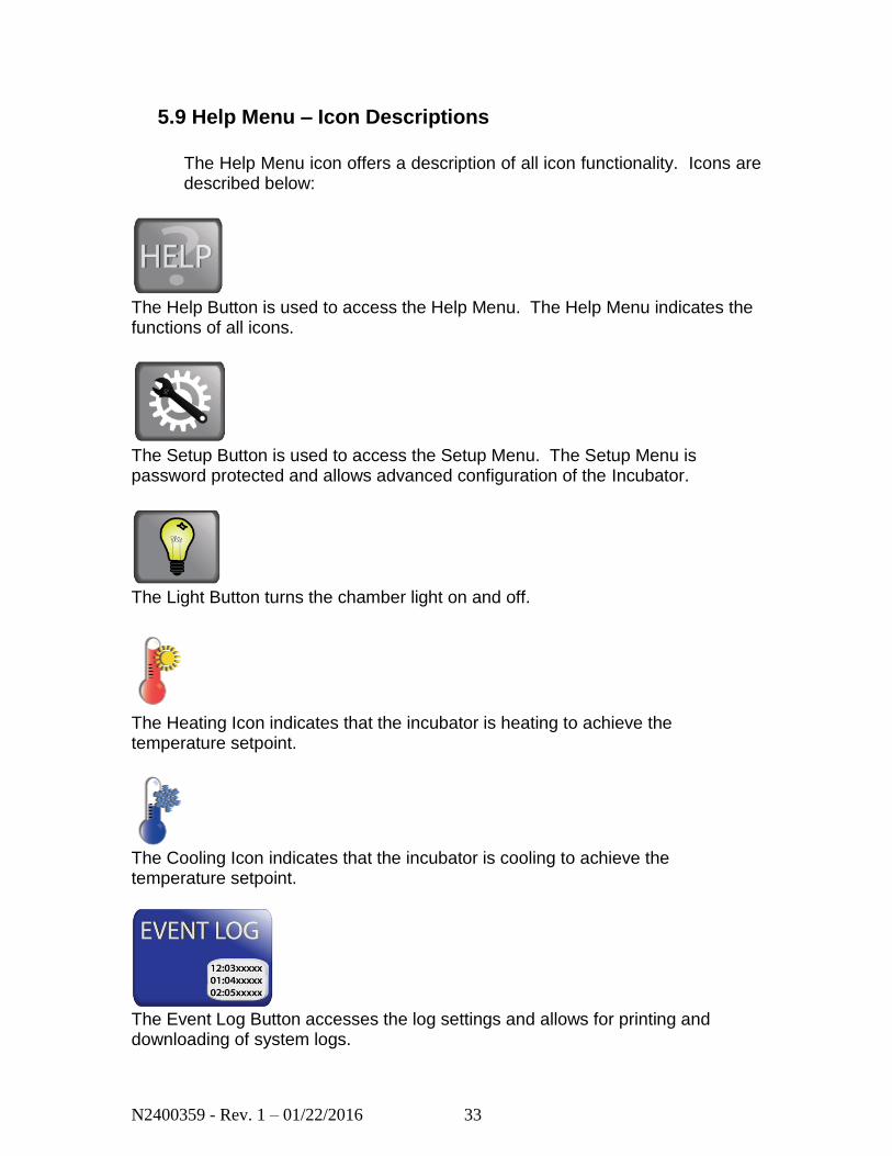
5.9 Help Menu – Icon Descriptions
The Help Menu icon offers a description of all icon functionality. Icons are described below:
The Help Button is used to access the Help Menu. The Help Menu indicates the functions of all icons.
The Setup Button is used to access the Setup Menu. The Setup Menu is password protected and allows advanced configuration of the Incubator.
The Light Button turns the chamber light on and off.
The Heating Icon indicates that the incubator is heating to achieve the temperature setpoint.
The Cooling Icon indicates that the incubator is cooling to achieve the temperature setpoint.
The Event Log Button accesses the log settings and allows for printing and downloading of system logs.
N2400359 - Rev. 1 – 01/22/2016 34
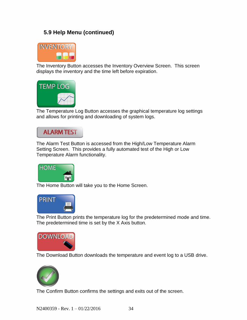
5.9 Help Menu (continued)
The Inventory Button accesses the Inventory Overview Screen. This screen displays the inventory and the time left before expiration.
The Temperature Log Button accesses the graphical temperature log settings and allows for printing and downloading of system logs.
The Alarm Test Button is accessed from the High/Low Temperature Alarm Setting Screen. This provides a fully automated test of the High or Low Temperature Alarm functionality.
The Home Button will take you to the Home Screen.
The Print Button prints the temperature log for the predetermined mode and time. The predetermined time is set by the X Axis button.
The Download Button downloads the temperature and event log to a USB drive.
The Confirm Button confirms the settings and exits out of the screen.
N2400359 - Rev. 1 – 01/22/2016 35
5.9 Help Menu (continued)
The Cancel Button exits out of a screen without saving changes.
The X Axis button sets the time frame for the displayed graph and printed graph.
The Password Button is used to change the current password. The Password is used to change settings in the Settings Screen. The Default Password is 1234.
The Temperature Setpoint Button is used to change the temperature setpoint. The default temperature is set to 22.0˚C.
The Calibration Button is used to calibrate the incubator temperature.
The Temperature Alarm Button is used to set the setpoints for the High and Low Temperature Alarms. This menu also has functionality to automatically test that each alarm operates as intended (detailed in Section 5.7).
N2400359 - Rev. 1 – 01/22/2016 36
5.9 Help Menu (continued)
The Volume Button changes the volume of the incubator alarm.
The Inventory Timer Button changes the timers and notifications associated with the inventory management system.
The Time Button sets the Time and Date of the unit.
The USB Button allows for a complete system log download or the uploading of firmware.
The Network Button allows for enabling and configuration of the network settings.
The Power Down button initiates a power down sequence so that the unit can be removed from power. This stops all data logging and alarms and disables the battery backup.
N2400359 - Rev. 1 – 01/22/2016 37
5.9 Help Menu (continued)
Agitation Alarm Icon – The system has detected that agitation is not taking place.
General Equipment Alarm – The System has detected a general equipment alarm with the thermoelectric module fans.
Door Alarm – The system has detected that the door has been opened for an extended period of time.
Network Alarm – The system has detected an external network issue.
High Temperature Alarm – The temperature has risen above the high temperature alarm setpoint.
Low Temperature Alarm – The temperature has dropped below the low temperature alarm setpoint.
N2400359 - Rev. 1 – 01/22/2016 38
5.9 Help Menu (continued)
Battery Alarm – The system has detected an issue with the batteries in the battery backup system or the system has lost main power and has used the battery backup to log data.
Expiration Warning Notification - There is inventory in the unit that is close to expiring. This is configurable to appear whenever an inventory shelf turns red and/or yellow in the inventory management system.
N2400359 - Rev. 1 – 01/22/2016 39
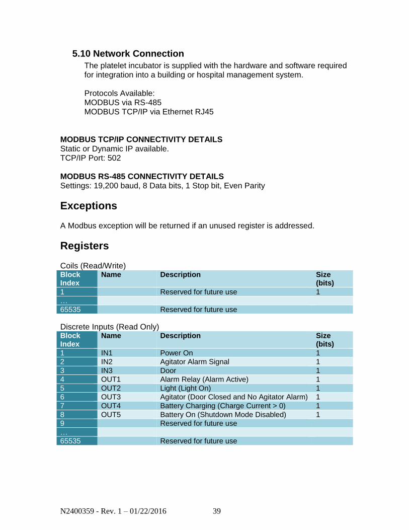
5.10 Network Connection
The platelet incubator is supplied with the hardware and software required for integration into a building or hospital management system. Protocols Available: MODBUS via RS-485 MODBUS TCP/IP via Ethernet RJ45
MODBUS TCP/IP CONNECTIVITY DETAILS Static or Dynamic IP available. TCP/IP Port: 502 MODBUS RS-485 CONNECTIVITY DETAILS Settings: 19,200 baud, 8 Data bits, 1 Stop bit, Even Parity
Exceptions A Modbus exception will be returned if an unused register is addressed.
Registers Coils (Read/Write) Block Index
Name Description Size (bits)
1 Reserved for future use 1
…
65535 Reserved for future use
Discrete Inputs (Read Only) Block Index
Name Description Size (bits)
1 IN1 Power On 1
2 IN2 Agitator Alarm Signal 1
3 IN3 Door 1
4 OUT1 Alarm Relay (Alarm Active) 1
5 OUT2 Light (Light On) 1
6 OUT3 Agitator (Door Closed and No Agitator Alarm) 1
7 OUT4 Battery Charging (Charge Current > 0) 1
8 OUT5 Battery On (Shutdown Mode Disabled) 1
9 Reserved for future use
…
65535 Reserved for future use
N2400359 - Rev. 1 – 01/22/2016 40
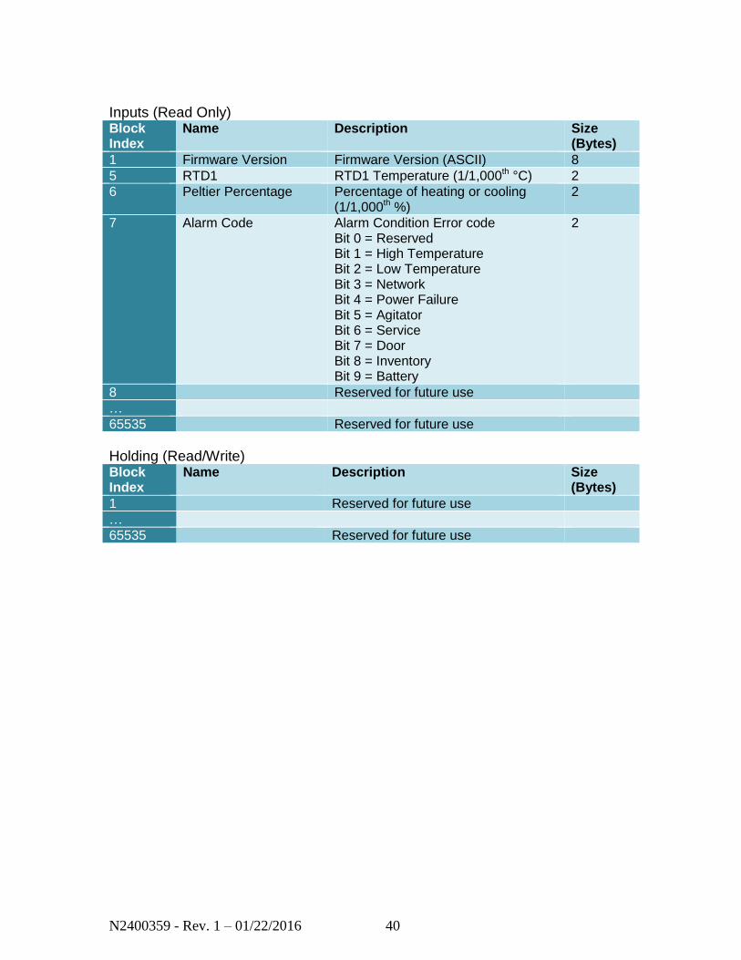
Inputs (Read Only) Block Index
Name Description Size (Bytes)
1 Firmware Version Firmware Version (ASCII) 8
5 RTD1 RTD1 Temperature (1/1,000th °C) 2
6 Peltier Percentage Percentage of heating or cooling (1/1,000th %)
2
7 Alarm Code Alarm Condition Error code Bit 0 = Reserved Bit 1 = High Temperature Bit 2 = Low Temperature Bit 3 = Network Bit 4 = Power Failure Bit 5 = Agitator Bit 6 = Service Bit 7 = Door Bit 8 = Inventory Bit 9 = Battery
2
8 Reserved for future use
…
65535 Reserved for future use
Holding (Read/Write) Block Index
Name Description Size (Bytes)
1 Reserved for future use
…
65535 Reserved for future use
N2400359 - Rev. 1 – 01/22/2016 41
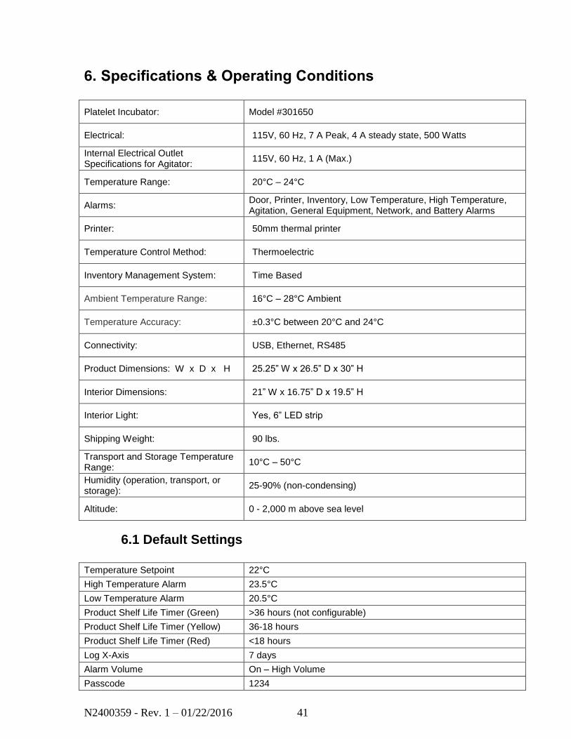
6. Specifications & Operating Conditions
Platelet Incubator: Model #301650
Electrical: 115V, 60 Hz, 7 A Peak, 4 A steady state, 500 Watts
Internal Electrical Outlet Specifications for Agitator:
115V, 60 Hz, 1 A (Max.)
Temperature Range: 20°C – 24°C
Alarms: Door, Printer, Inventory, Low Temperature, High Temperature, Agitation, General Equipment, Network, and Battery Alarms
Printer: 50mm thermal printer
Temperature Control Method: Thermoelectric
Inventory Management System: Time Based
Ambient Temperature Range: 16°C – 28°C Ambient
Temperature Accuracy: ±0.3°C between 20°C and 24°C
Connectivity: USB, Ethernet, RS485
Product Dimensions: W x D x H 25.25” W x 26.5” D x 30” H
Interior Dimensions: 21” W x 16.75” D x 19.5” H
Interior Light: Yes, 6” LED strip
Shipping Weight: 90 lbs.
Transport and Storage Temperature Range:
10°C – 50°C
Humidity (operation, transport, or storage):
25-90% (non-condensing)
Altitude: 0 - 2,000 m above sea level
6.1 Default Settings
Temperature Setpoint 22°C
High Temperature Alarm 23.5°C
Low Temperature Alarm 20.5°C
Product Shelf Life Timer (Green) >36 hours (not configurable)
Product Shelf Life Timer (Yellow) 36-18 hours
Product Shelf Life Timer (Red) <18 hours
Log X-Axis 7 days
Alarm Volume On – High Volume
Passcode 1234
N2400359 - Rev. 1 – 01/22/2016 42
7. Maintenance and Service
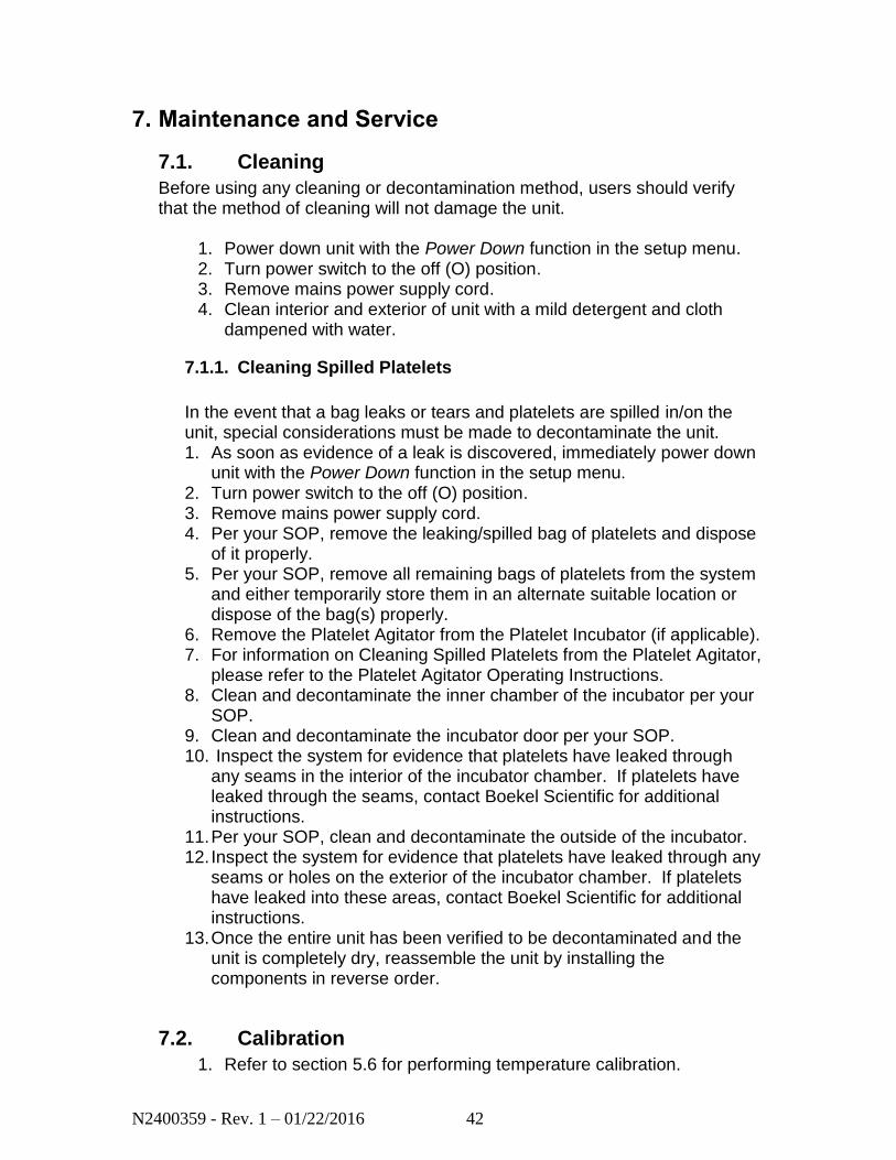
7.1. Cleaning
Before using any cleaning or decontamination method, users should verify that the method of cleaning will not damage the unit.
1. Power down unit with the Power Down function in the setup menu. 2. Turn power switch to the off (O) position. 3. Remove mains power supply cord. 4. Clean interior and exterior of unit with a mild detergent and cloth
dampened with water.
7.1.1. Cleaning Spilled Platelets
In the event that a bag leaks or tears and platelets are spilled in/on the unit, special considerations must be made to decontaminate the unit. 1. As soon as evidence of a leak is discovered, immediately power down
unit with the Power Down function in the setup menu. 2. Turn power switch to the off (O) position. 3. Remove mains power supply cord. 4. Per your SOP, remove the leaking/spilled bag of platelets and dispose
of it properly. 5. Per your SOP, remove all remaining bags of platelets from the system
and either temporarily store them in an alternate suitable location or dispose of the bag(s) properly.
6. Remove the Platelet Agitator from the Platelet Incubator (if applicable). 7. For information on Cleaning Spilled Platelets from the Platelet Agitator,
please refer to the Platelet Agitator Operating Instructions. 8. Clean and decontaminate the inner chamber of the incubator per your
SOP. 9. Clean and decontaminate the incubator door per your SOP. 10. Inspect the system for evidence that platelets have leaked through
any seams in the interior of the incubator chamber. If platelets have leaked through the seams, contact Boekel Scientific for additional instructions.
11. Per your SOP, clean and decontaminate the outside of the incubator. 12. Inspect the system for evidence that platelets have leaked through any
seams or holes on the exterior of the incubator chamber. If platelets have leaked into these areas, contact Boekel Scientific for additional instructions.
13. Once the entire unit has been verified to be decontaminated and the unit is completely dry, reassemble the unit by installing the components in reverse order.
7.2. Calibration
1. Refer to section 5.6 for performing temperature calibration.

N2400359 - Rev. 1 – 01/22/2016 43
7.3. Replacement of Fuses
To change the main incubator fuses:
1. Enter the setup menu and press the Power Down button. 2. Turn power switch to the off (O) position. 3. Disconnect the unit from the power supply. 4. Remove the line cord from the power entry module on the back of the
unit. 5. Pull back on the fuse drawer catch (located on top of power entry
module). 6. Pull out the fuse drawer. 7. Check and replace with the correct fuses if necessary. The fuses must
be 5mm x 20mm, fast acting, rated at 8A 250V. 8. Push the drawer back in and reconnect the unit to the power supply.
To change the agitator chamber fuse:
1. Enter the setup menu and press the Power Down button. 2. Turn the incubator power switch to the off (O) position. 3. Disconnect the unit from the power supply. 4. Remove the line cord from the power entry module on the back of the
incubator unit. 5. Power down and disconnect the agitator. 6. Remove the agitator from the incubator chamber. 7. Unscrew the fuse holder. 8. Check and replace with the correct fuses if necessary. The fuses
must be 5x20mm, 1A, 250V fast-acting. 9. Push the drawer back in and reconnect the unit to the power supply.

N2400359 - Rev. 1 – 01/22/2016 44
8. Troubleshooting
Symptoms Possible Cause Corrective Action
Power
The unit does not power on. Power cord not connected to Electrical receptacle on Unit, and/or Wall outlet
Power supply failure
A fuse has blown
Malfunctioning Power Key
Malfunctioning Control System
Fit the power line cord into the IEC power socket on the rear of the unit and verify if plugged into a properly grounded outlet
Verify that power source is active and regulated
Replace fuse
Contact Boekel Scientific for Service
Contact Boekel Scientific for Service
Temperature Control
The temperature does not stabilize
Not enough clearance around incubator
Faulty Temperature Sensor
Confirm Ambient Temperature is within the recommended range
Confirm there is 3 inches of clearance around the incubator
Contact Boekel Scientific for Service
The displayed temperature does not match a calibrated temperature measuring device
Unit is in need of calibration
Faulty Temperature Sensor
Refer to Calibration Section
Contact Boekel Scientific for Service
Alarm Failure
Audible alarm does not sound
Alarm/notification does not generate an audible alarm
Buzzer volume has been turned off
Faulty piezo buzzer
Check Alarms section of this document to ensure the alarm is supposed to be audible for the particular event
Turn on the alarm volume through the settings menu
Contact Boekel Scientific for Service
N2400359 - Rev. 1 – 01/22/2016 45
9. Warranty and Service
9.1. Warranty
When used in the appropriate laboratory conditions and in accordance with these operating instructions, Boekel Scientific warrants this product to be free of defective parts, material and workmanship for a period of two years from the date of shipment. The liability of Boekel Scientific for any defective equipment during the warranty period shall be limited to the repair of defective equipment or replacement thereof without charge for parts or labor.
9.2. Service
A Boekel Scientific Returned Material Authorization (RMA) number provided by Boekel Scientific is required before any Boekel products are returned for any reason. Contact Boekel Customer Service at 1-800-336-6929. A Decontamination Certificate must be completed, signed by the user, and returned to Boekel Scientific prior to receiving the RMA number. Please be sure to mark the outside of the returned goods package with this RMA number to ensure prompt handling.
Boekel Scientific 855 Pennsylvania Blvd. Feasterville, PA 19053 Phone: (215) 396-8200 or (800) 336-6929 Fax: (215) 396-8264 Email: [email protected]