Platelet Agitator Service Manual - Helmer Scientific · • The agitator communication switch is...
20
360391/A Platelet Agitator Service Manual i.Series ® -Pro Models Countertop PF15-Pro PF48-Pro PF96-Pro
Transcript of Platelet Agitator Service Manual - Helmer Scientific · • The agitator communication switch is...

360391/A
Platelet Agitator Service Manuali.Series® -Pro Models
CountertopPF15-Pro PF48-Pro PF96-Pro
Document Updates The document is furnished for information use only, is subject to change without notice and should not be construed as a commitment by Helmer Scientific. Helmer Scientific assumes no responsibility or liability for any errors or inaccuracies that may appear in the informational content contained in this material. For the purpose of clarity, Helmer Scientific considers only the most recent revision of this document to be valid.
Notices and DisclaimersConfidential / Proprietary NoticesUse of any portion(s) of this document to copy, translate, disassemble or decompile, or create or attempt to create by reverse engineering or otherwise replicate the information from Helmer Scientific products is expressly prohibited.
Copyright and TrademarkHelmer®, i.Series®, AgiTrak™ and Rel.i™ are registered trademarks or trademarks of Helmer, Inc. in the United States of America. Copyright © 2019 Helmer, Inc. All other trademarks and registered trademarks are the property of their respective owners.Helmer, Inc., doing business as (DBA) Helmer Scientific and Helmer.
DisclaimerThis manual is intended as a guide to provide the operator with necessary instructions on the proper use and maintenance of certain Helmer Scientific products.Any failure to follow the instructions as described could result in impaired product function, injury to the operator or others, or void applicable product warranties. Helmer Scientific accepts no responsibility for liability resulting from improper use or maintenance of its products.The screenshots and component images appearing in this guide are provided for illustrative purposes only, and may vary slightly from the actual software screens and/or product components
Helmer Scientific14400 Bergen BoulevardNoblesville, IN 46060 USA
www.helmerinc.com Part No. 360391/ Rev A
Document HistoryRevision Date CO Supersession Revision DescriptionA 22 JUL 2019 14834 N/A Initial Release
* Date submitted for Change Order review. Actual release date may vary.

Helmer Scientific Platelet Agitator Service Manual
360391/A ii
Contents1 About this Manual . . . . . . . . . . . . . . . . . . . . . . . . . . . . . . . . . . . . . . . . . . . . . . . . . . . . . . . . . . . . . . . . . . . . . . . . . . . . . . . . . . . . . . . . . . . . . . . . 3
1.1 Intended Audience . . . . . . . . . . . . . . . . . . . . . . . . . . . . . . . . . . . . . . . . . . . . . . . . . . . . . . . . . . . . . . . . . . . . . . . . . . . . . . . . . . . . . . . . . . 31.2 Model Reference . . . . . . . . . . . . . . . . . . . . . . . . . . . . . . . . . . . . . . . . . . . . . . . . . . . . . . . . . . . . . . . . . . . . . . . . . . . . . . . . . . . . . . . . . . . . 31.3 Intended Use . . . . . . . . . . . . . . . . . . . . . . . . . . . . . . . . . . . . . . . . . . . . . . . . . . . . . . . . . . . . . . . . . . . . . . . . . . . . . . . . . . . . . . . . . . . . . . . 31.4 Safety Symbols and Precautions . . . . . . . . . . . . . . . . . . . . . . . . . . . . . . . . . . . . . . . . . . . . . . . . . . . . . . . . . . . . . . . . . . . . . . . . . . . . . . . 31.5 Avoiding Injury . . . . . . . . . . . . . . . . . . . . . . . . . . . . . . . . . . . . . . . . . . . . . . . . . . . . . . . . . . . . . . . . . . . . . . . . . . . . . . . . . . . . . . . . . . . . . . 41.6 Product Labels . . . . . . . . . . . . . . . . . . . . . . . . . . . . . . . . . . . . . . . . . . . . . . . . . . . . . . . . . . . . . . . . . . . . . . . . . . . . . . . . . . . . . . . . . . . . . 5
2 InstallationandConfiguration . . . . . . . . . . . . . . . . . . . . . . . . . . . . . . . . . . . . . . . . . . . . . . . . . . . . . . . . . . . . . . . . . . . . . . . . . . . . . . . . . . . . . . 62.1 Location Requirements . . . . . . . . . . . . . . . . . . . . . . . . . . . . . . . . . . . . . . . . . . . . . . . . . . . . . . . . . . . . . . . . . . . . . . . . . . . . . . . . . . . . . . . 62.2 Connect Power Supply . . . . . . . . . . . . . . . . . . . . . . . . . . . . . . . . . . . . . . . . . . . . . . . . . . . . . . . . . . . . . . . . . . . . . . . . . . . . . . . . . . . . . . . 62.3 Mounting Brackets . . . . . . . . . . . . . . . . . . . . . . . . . . . . . . . . . . . . . . . . . . . . . . . . . . . . . . . . . . . . . . . . . . . . . . . . . . . . . . . . . . . . . . . . . . 62.4 Placement Leveling and Setup . . . . . . . . . . . . . . . . . . . . . . . . . . . . . . . . . . . . . . . . . . . . . . . . . . . . . . . . . . . . . . . . . . . . . . . . . . . . . . . . . 72.5 ConfigurePlateletAgitatorforUseinaPlateletIncubator(Optional) . . . . . . . . . . . . . . . . . . . . . . . . . . . . . . . . . . . . . . . . . . . . . . . . . . . . 72.6 StorageConfiguration . . . . . . . . . . . . . . . . . . . . . . . . . . . . . . . . . . . . . . . . . . . . . . . . . . . . . . . . . . . . . . . . . . . . . . . . . . . . . . . . . . . . . . . . 82.7 External Monitoring Devices . . . . . . . . . . . . . . . . . . . . . . . . . . . . . . . . . . . . . . . . . . . . . . . . . . . . . . . . . . . . . . . . . . . . . . . . . . . . . . . . . . . 92.8 Alarm Reference . . . . . . . . . . . . . . . . . . . . . . . . . . . . . . . . . . . . . . . . . . . . . . . . . . . . . . . . . . . . . . . . . . . . . . . . . . . . . . . . . . . . . . . . . . . 10
3 Maintenance . . . . . . . . . . . . . . . . . . . . . . . . . . . . . . . . . . . . . . . . . . . . . . . . . . . . . . . . . . . . . . . . . . . . . . . . . . . . . . . . . . . . . . . . . . . . . . . . . . . . .113.1 Remove / Replace Trolley . . . . . . . . . . . . . . . . . . . . . . . . . . . . . . . . . . . . . . . . . . . . . . . . . . . . . . . . . . . . . . . . . . . . . . . . . . . . . . . . . . . . .113.2 Motion Alarm Test . . . . . . . . . . . . . . . . . . . . . . . . . . . . . . . . . . . . . . . . . . . . . . . . . . . . . . . . . . . . . . . . . . . . . . . . . . . . . . . . . . . . . . . . . . 123.3 Test and Replace Motion Alarm Back-up Battery . . . . . . . . . . . . . . . . . . . . . . . . . . . . . . . . . . . . . . . . . . . . . . . . . . . . . . . . . . . . . . . . . . 123.4 Clean Agitator . . . . . . . . . . . . . . . . . . . . . . . . . . . . . . . . . . . . . . . . . . . . . . . . . . . . . . . . . . . . . . . . . . . . . . . . . . . . . . . . . . . . . . . . . . . . . 12
4 Troubleshooting . . . . . . . . . . . . . . . . . . . . . . . . . . . . . . . . . . . . . . . . . . . . . . . . . . . . . . . . . . . . . . . . . . . . . . . . . . . . . . . . . . . . . . . . . . . . . . . . 134.1 GeneralOperationProblems . . . . . . . . . . . . . . . . . . . . . . . . . . . . . . . . . . . . . . . . . . . . . . . . . . . . . . . . . . . . . . . . . . . . . . . . . . . . . . . . . 134.2 Alarm Activation Problems . . . . . . . . . . . . . . . . . . . . . . . . . . . . . . . . . . . . . . . . . . . . . . . . . . . . . . . . . . . . . . . . . . . . . . . . . . . . . . . . . . . 13
5 Parts . . . . . . . . . . . . . . . . . . . . . . . . . . . . . . . . . . . . . . . . . . . . . . . . . . . . . . . . . . . . . . . . . . . . . . . . . . . . . . . . . . . . . . . . . . . . . . . . . . . . . . . . . . 14
Appendix A: Wiring Diagram . . . . . . . . . . . . . . . . . . . . . . . . . . . . . . . . . . . . . . . . . . . . . . . . . . . . . . . . . . . . . . . . . . . . . . . . . . . . . . . . . . . . . . . . . . 16
Appendix B: Warranty . . . . . . . . . . . . . . . . . . . . . . . . . . . . . . . . . . . . . . . . . . . . . . . . . . . . . . . . . . . . . . . . . . . . . . . . . . . . . . . . . . . . . . . . . . . . . . . 17

Helmer Scientific Platelet Agitator Service Manual
360391/A 3
1 About this Manual1.1 Intended AudienceThis manual provides information on how to use the platelet agitator Pro. It is intended for use by end users of the platelet agitator and authorized service technicians.
1.2 Model ReferenceThismanualcoversallProSeriesplateletagitatorswhichmaybeidentifiedbysizeormodelnumber.
1.3 Intended Use Note
This equipment has been tested and found to comply with the limits for a Class A digital device, pursuant to part 15 of the FCC Rules. These limits are designed to provide reasonable protection against harmful interference when the equipment is operated in a commercial environment. This equipment generates, uses and can radiate radio frequency energy and, if not installed and used in accordance with the instruction manual, may cause harmful interference to radio communications.Operationofthisequipmentinaresidentialareaislikelytocauseharmfulinterferenceinwhichcasetheuser will be required to correct the interference at his own expense.
Helmer platelet agitators are intended to provide controlled agitation required for the storage of platelet products.The devices are intended to be operated by personnel who have procedures in place for meeting FDA, AABB, EU or any other applicable regulations for the processing and storage of platelet products.
1.4 Safety Symbols and Precautions
Symbols and precautions found in this document
The following symbols are used in this manual to emphasize certain details for the user:
Task Indicates procedures which need to be followed.
Note Provides useful information regarding a procedure or operating technique when using Helmer Scientificproducts.
NOTICE Advises the user against initiating an action or creating a situation which could result in damage to equipment; personal injury is unlikely.
CAUTION Advises the user against initiating an action or creating a situation which could result in damage to equipment or impair the quality of the products or cause minor injury.
WARNING Advises the user against initiating an action or creating a situation which could result in damage to equipment and serious personal injury to a patient or the user.
Authorized representative in the European CommunityEC REP

Helmer Scientific Platelet Agitator Service Manual
360391/A 4
Symbols found on the units
The following symbols may be found on the agitator or agitator packaging:
0086CEMark(Europeanunitsonly)
Earth / ground terminal
Caution: Risk of damage to equipment or danger to operator Protective earth / ground terminal
Caution: Hot surfaceProduct falls under the scope of the WEEE (WasteElectricalandElectronicEquipment)directive.
Caution: Shock / electrical hazard
1.5 Avoiding Injury
Review safety instructions before installing, using, or maintaining the equipment. ♦ Before moving unit, remove contents from the drawers. ♦ Do not open multiple drawers at the same time. ♦ Before moving unit, disconnect the DC power cord and secure the cord. ♦ When moving unit, use assistance from a second person. ♦ Never physically restrict any moving component. ♦ Avoid removing electrical service panels and access panels unless so instructed. ♦ Keep hands away from pinch points when agitation motion is enabled. ♦ Avoid sharp edges when working inside the electrical compartment. ♦ Ensure biological materials are stored at recommended temperatures determined by standards, literature, or good
laboratory practices. ♦ Proceed with caution when adding and removing samples from the platelet agitator. ♦ Use only manufacturer supplied power supply/cord when operating stand-alone or within incubator. ♦ UsingtheequipmentinamannernotspecifiedbyHelmerScientificmayimpairtheprotectionprovidedbytheequipment.. ♦ Theplateletagitatorisnotconsideredtobeastoragecabinetforflammableorhazardousmaterials.
CAUTIONDecontaminatepartspriortosendingforserviceorrepair.ContactHelmerScientificoryourdistributorfordecontamination instructions and a Return Authorization Number.

Helmer Scientific Platelet Agitator Service Manual
360391/A 5
1.6 Product Labels Note
Service information varies depending on the model and power requirements.
Thisinformationappearsontheproductspecificationlabel,onthebackoftheplateletagitator.
C
A
B
Sample Product Specification label.
Label Description
A Model
B Serialnumber(SN)
C Power requirements
Helmer Scientific Platelet Agitator Service Manual
360391/A 6
2 InstallationandConfiguration2.1 Location Requirements ♦ To ensure continuous operation of linearly shifting loads, the location surface must be level and adequately accommodate the full
weight of the agitator when loaded with product. ♦ Hasagroundedoutletmeetingtheelectricalrequirementslistedontheproductspecificationlabel. ♦ Is clear of direct sunlight, high temperature sources, and heating and air conditioning vents. ♦ Minimum0.5”(13mm)behind. ♦ Minimum0.75”(20mm)onleftandrightsides. ♦ Meetslimitsspecifiedforambienttemperature(15˚Cto35˚C)andrelativehumidity.
NoteAdd1.5”(38mm)tothewidthtoaccommodatethetrolleyframewhenagitationmotionisenabled.
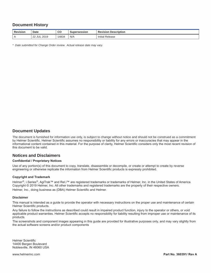
2.2 Connect Power SupplyTheplateletagitatormaybeusedinastand-aloneconfiguration.Apowersupplywithadaptableplugsisavailableforstand-aloneuse. Select and install the desired plug prior to attaching the power supply to the agitator. The power supply is not used when configuredinsideaHelmerProSeriesPlateletIncubator.
ConfigureandAttachPowerSupply1. Remove the cover plate by using the thumb to push and hold the spring loaded locking key downward while sliding the plate forward. Retain the cover plate in secure location for future use.2. Selectthedesiredplugandslideinplaceuntilitlocks(aclickingsoundwilloccur).Makesuretheplugisfirmlyattached.3. Attachthepowersupplytotheplateletagitator,andensuretherotatinglockisfingertightpriortopluggingpowersupply into facility AC.
2.3 Mounting BracketsMountingbracketsareincludedandmaybeinstalledforuseinsidetheProseriesincubatororinstand-aloneconfiguration.
Install Mounting Brackets1. Carefully place the agitator on its back on a solid surface allowing access to the bottom of the unit.2. Locate the two nutserts in the right or left side toward the front of the unit and align with the two holes in the mounting bracket.3. Hand thread the screws through each hole, and secure using a #2 Phillips screwdriver.4. Repeat steps 2 and 3 for the opposite side.5. Return the agitator to the upright position.6. Carefully place the agitator in the desired location aligning the hole in each bracket with the holes in the mounting surface. (IfmountinginsideaProseriesincubator,removescrewsintheflooroftheincubatorpriortoinstallingtheagitator).

Helmer Scientific Platelet Agitator Service Manual
360391/A 7
2.4 Placement Leveling and Setup (Stand-alone)
CAUTION• To prevent damage, do not use trolley or trolley drawer to lift agitator.• The communication switch is fragile, do not use excessive force when changing the setting.
NOTICE• When lifting platelet agitator, lift using the ends of the base.• If the base is not accessible, lift using the ends of the trolley
Notes• Leveling feet may crack or wear over time. Check leveling feet periodically and replace as needed.• For setpoint of 72 CPM, rotate the arrow into the center of the green zone. This is the expanded 72 CPM setpoint area.• Foradditionalinformationregardingagitatorsetup,refertothePlateletAgitatorProOperationManual.
1. Place platelet agitator on sturdy surface.2. Adjust leveling feet to ensure platelet agitator is level.3. Usingasmallflatheadscrewdriver,turnthecommunicationswitchtotheXposition. Ensurethearrow(showninredforvisibilityinthepicture)ispointingtotheX.
2.5 ConfigurePlateletAgitatorforUseinaPlateletIncubator(Optional)ProSeriesplateletincubatorsmayonlybefittedwithProSeriesplateletagitators.WheninstalledinaProSeriesplateletincubator,the Pro Series platelet agitator can be monitored by the platelet incubator’s AgiTrak™ system. The AgiTrak™ system receives alarm information through a direct connection from the platelet agitator’s alarm system to the platelet incubator’s alarm system.
Platelet Agitator and Platelet Incubator Compatibility
NoteOnlyProSeriesplateletincubatorscanmonitorProSeriesplateletagitators.
Compatible Helmer Platelet Agitator Platelet Incubator
PF15-Pro PC100-Pro
PF48-Pro PC900-Pro
PF96-Pro PC1200-Pro
Install a Platelet Agitator in the Platelet Incubator
Notes• Foradditionalinstructiononconfiguringaplateletagitatorinaplateletincubator,refertothePlateletIncubatorPro OperationManual.• Ensure data cable is carefully positioned to the right of the agitator to prevent damage caused by agitation motion.• The agitator communication switch is fragile, do not use excessive force when changing the setting. • To ensure continuous operation of linearly shifting loads, the location surface must adequately accommodate the full weight of the incubator with installed agitator when loaded with product. • Use only the manufacturer supplied coiled DC power cord when installing the Pro series agitator in a Pro series Incubator.• Ensure the incubator AC power and battery back-up power are switched OFF prior to connecting the agitator power cord to the incubator.• Installation of agitator anchor brackets is recommended when an installed agitator is set at a speed greater than 72cyclesperminute(CPM).Anchorbracketsareincludedwiththeagitator.• The agitator motion alarm switch must be ON, and volume turned up to provide audible alarm backup in the event communication is lost between the agitator and incubator.

Helmer Scientific Platelet Agitator Service Manual
360391/A 8
PC900-Pro with PF48-Pro installed. Agitator communication switch
Helmer Pro Series platelet agitators can be installed inside Helmer Pro Series platelet incubators. The agitator can be connected to the incubator through a data cable. The connection allows the platelet incubator to monitor the platelet agitator motion, and to sound an alarm when agitation motion stops. Power is supplied to the agitator through the coiled DC power cable. Connect the data cable and DC power cable supplied with the incubator prior to placing the agitator inside the incubator. The power cable has a rotating locking feature on each end to ensure a secureconnection.Wheninstallingtheagitatorinsidetheincubator,fingertighteneachrotatinglock.Theagitatorcommunicationswitchmustbesettoposition1(showninredforvisibilityinthepictureabove)foruseintheincubator.
2.6 StorageConfigurationDrawers can be removed or moved to adjust storage space as needed.
CAUTIONTo avoid injury and prevent damage to the agitator, ensure both left and right side drawer stop panels are fully installed prior to operating the agitator.
Remove and Replace Drawers1. Remove the thumb screws securing the drawer stop panels to the left and right sides of the agitator.(Notetheorientationofeachpanel)2. Carefully pull each panel from the agitator and set panels and thumb screws aside.3. Slidethedrawer(s)outandremove.4. Reinstalldrawer(s)indesiredlocationbyaligningtheouteredgesofthedrawerwiththeslots in the drawer guides and push inward.5. Reinstall both drawer stop panels in the same orientation as removed, and secure with thumb screwsensuringtheyarefingertight.
Install Label Holders (optional)1. Insert the tabs on the label holder into the slots on the drawer.2. Pivot the holder around the drawer handle and align the hole on the label holder with the corresponding hole on the drawer.3. Push thumb screw through the hole in the label holder and through the hole in the drawer to secure.
Agitator Power Connection
Thumb Screws
Helmer Scientific Platelet Agitator Service Manual
360391/A 9
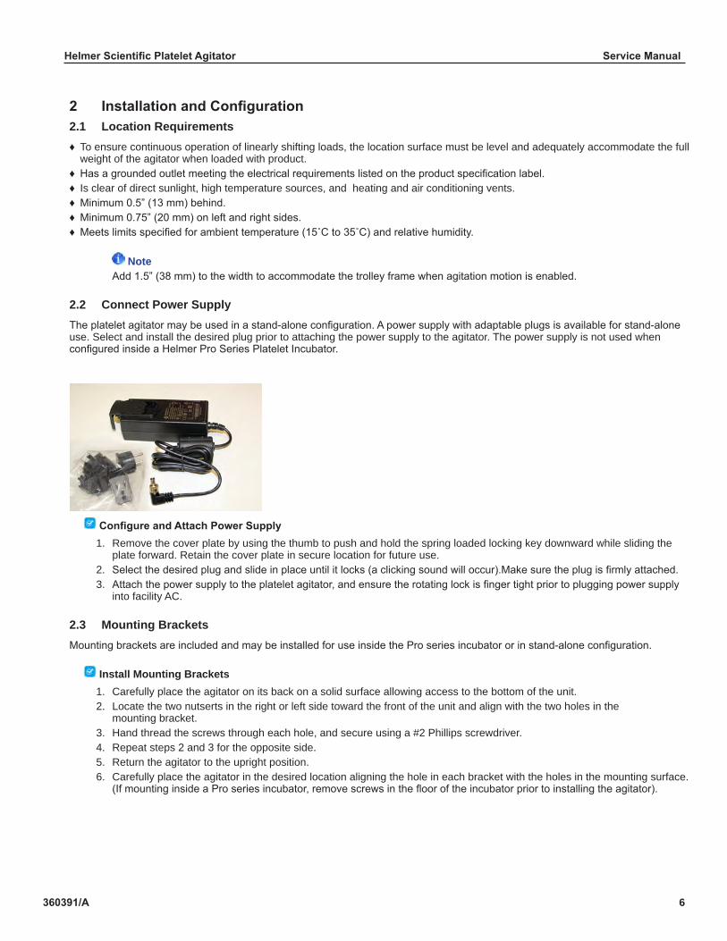
2.7 External Monitoring DevicesThe agitator has two independent interfaces, each with spring loaded terminal pins for connecting external monitoring devices. Theseinterfacesarelocateddirectlyontheagitatorcontrolboardwhichislocatedinthebaseoftheagitator(Thetrolleymustberemovedtoaccesstheseinterfaces).Oneinterface(J2)isasetofdrycontactswithnormallyopenornormallyclosedcontactsdependinguponconnectorterminalsused.Theotherinterface(J3)setprovidesaswitched9-15V,100mApoweredoutput.Requirementsforyouralarmsystemdeterminewhichalarmwires(userprovided)mustconnecttospecificconnectorterminals.
NoteWhen installed in a Pro series incubator, agitator alarms are communicated to the incubator.
J2 Dry Contact Remote Alarm InterfaceTheterminalsontheJ2alarminterfacehaveamaximumloadcapacityof1Aat33V(AC)RMSor70V(DC).Thedrycontactremote alarm interface is a relay switch with three terminals.
♦ Common(COM) ♦ NormallyOpen(NO) ♦ NormallyClosed(NC)
CAUTION• TerminalsonJ2aredrycontactsanddonotsupplyvoltage.TheinterfacecircuitisNOorNCdependingupon connectorterminalsused.Theseconnectionsareintendedforusewithanenduser’sexternalalarmsystem(s)that interfacetoNOorNCdrycontacts.• Ifanexternalpowersupplyexceeding33V(AC)RMSor70V(DC)isconnectedtothe(J2)remotealarmcircuit,the remote alarm will not function properly; may be damaged; or may result in injury to the user.
J3 Agitator Powered Remote Alarm InterfaceTheterminalsontheJ3alarminterfacehaveamaximumsupplycapacityof100mAfrom9-15V(DC).Theagitatorpoweredremote alarm interface has three terminals.
♦ Reference9-15V ♦ NormallyOpen(NO)<<Inanalarmcondition,9-15Vwillbeconnectedtothisterminal ♦ CircuitGroundReference(GND)
CAUTION• If any external power supply is connected to the J3 remote alarm circuit, the remote alarm or Agitator itself will not function properly; may be damaged; or may result in injury to the user.• TheAgitatordoesnotlimittheoutputcurrentthruJ3–itisrequiredthattheenduser’scentralalarmsystem(s)interface doesnotpullgreaterthan100mAat9-15V(DC).
Connect to Remote Alarm Interface (J2 or J3)1. SwitchtheON/OFFswitchOFF and disconnect the power cable from the power receptacle.2. SwitchthemotionalarmON/OFFswitchOFF.3. Remove the trolley to access the agitator board in the base of the agitator.4. Route alarm wires into the agitator base through the rear access hole in the base.5. Onthealarmpanel,locatetheremotealarmterminals.6. Connect remote alarm wires to appropriate terminals, according to requirements for your alarm system.7. Useacabletietorelievestrainonalarmwires(asnecessary).8. Reinstall the trolley.9. Reconnectthepowercabletopowerreceptacle,andswitchtheON/OFF switch ON.10. SwitchthemotionalarmON/OFFswitchON.
Remote alarm interfaces.

Helmer Scientific Platelet Agitator Service Manual
360391/A 10
2.8 Alarm ReferenceIf an alarm condition is met, an alarm activates. Some alarms are visual only; others are visual and audible. Some Alarms are sentthroughtheremotealarminterface.Thetablebelowindicatesifanalarmisaudible(A),visual(V),orsentthroughtheremotealarminterface(R).
Notes• IfthemotionalarmswitchisONwithnoactivealarms,theLEDwillbeilluminated,solidred.• Alarm volume must be set to an audible level to receive an audible alarm.
Table 1. Alarm Reference
Alarm Alarm Type
Motion alarm A,R,V

Helmer Scientific Platelet Agitator Service Manual
360391/A 11
3 MaintenanceMaintenance tasks should be completed according to the schedule below.
Notes• These are recommended minimum requirements. Regulations for your organization or physical conditions at your organization may require maintenance items to be performed more frequently, or only by designated service personnel.• The Preventive Maintenance schedule provided below supersedes the schedule provided in the Platelet Agitator Pro OperationManual.
Table 4. Preventive Maintenance Schedule
TaskFrequency
Annually As Needed
Test the motion alarm. ü
Checkthe9VNiMHback-upbatteryforthemotionalarmsystemafteranextended power failure and change it if necessary, or change the battery if it has been in service for one year.
ü
Check moving parts for wear. Clean moving parts. ü
Replace moving parts if worn. ü
Clean the exterior of the platelet agitator. ü
Notes• Duringapowerfailure(whenthemotionalarmisenabled),theback-upbatteryprovidespowertothemotionalarm. If the back-up battery is not functioning, the motion alarm will not be activated.• If the back-up battery does not provide power to the alarm system during the motion alarm test, replace the battery.• If battery has been in service for one year, replace battery.• Useonlymanufacturerspecifiedrechargeablebatteryforreplacement(9VNiMHbatterywithacapacityof≥175mAh).
3.1 Remove / Replace TrolleyThe storage trolley must be removed when performing certain maintenance tasks.
Remove Trolley1. SwitchtheMotionAlarmON/OFFswitchOFF.2. SwitchthePowerON/OFFswitchOFF, and disconnect the power cable from the power receptacle.3. Removethethumbscrewssecuringthedrawerstoppanelstotheleftandrightsidesoftheagitatortrolley.(Notethe orientationofeachpanel)4. Carefully pull each panel from the agitator and set panels and thumb screws aside.5. Slidethedrawer(s)outandremove.6. Usea#2Phillipsscrewdrivertoloosenthefour(4)centerscrewsonthefloorofthetrolley.7. Slide the screw heads to the opposite end of the slots.8. Lift the trolley straight up and set aside.
Install Trolley1. Carefully place the trolley on the base aligning the back and sides of the trolley with the back and sides of the base. Ensure the motor arm roller is placed within the trolley plastic guide block.2. Slidethefour(4)centerscrewheadsinthefloorofthetrolleytotheoppositeendsoftheslots,andsecureusinga #2 Phillips screwdriver.3. Reinstall drawers in desired location by aligning the outer edges of the drawer with the slots in the drawer guides and push inward.4. Reinstallthedrawer(s)stoppanelsinthesameorientationasremoved,andsecurewiththumbscrewsensuringtheyare fingertight.5. Reconnectpowercabletopowerreceptacleand,switchthePowerON/OFFswitchON.6. SwitchtheMotionAlarmON/OFFswitchON.

Helmer Scientific Platelet Agitator Service Manual
360391/A 12
3.2 Motion Alarm TestTest the motion alarm to ensure it activates when the platelet agitator motion stops. The alarm may not activate immediately, depending on the motion alarm delay setting. If the alarm does not activate when it should, refer to Troubleshooting.
Notes• The motion alarm delay range is 10 - 600 seconds. When testing the alarm, be certain the set delay time has passed.• Whenthemotionalarmisactivated,theredLEDonthemotionalarmswitchwillflash.• The motion alarm is muted when the alarm volume is turned fully counterclockwise.
Test Motion Alarm1. EnsuretheAlarmVolumeissettoanaudiblelevelandtheAlarmDelayissettothe minimumdelay(asnotedbyredrotationalarrows).2. SwitchthePowerON/OFFswitchOFF to stop agitation. When the alarm delay period elapses, the motion alarm will activate. 3. SwitchthePowerON/OFFswitchON.
3.3 Test and Replace Motion Alarm Back-up BatteryThemotionalarmsystemispoweredbyDCpower,backedupbyarechargeable9VNiMHbattery.Thebatterychargeswhentheplatelet agitator is connected to its external AC/DC power supply. In the event of a facility AC power failure, agitation would stop and the battery will power the motion alarm.
Test Motion Alarm Back-up Battery1. EnsuretheAlarmVolumeissettoanaudiblelevelandtheAlarmDelayissettotheminimumdelay.2. EnsuretheMotionAlarmON/OFFswitchisON.3. SwitchthePowerON/OFFswitchOFF to stop agitation. When the alarm delay period elapses, the motion alarm will activate. If the motion alarm does not activate, replace the battery.4. SwitchthePowerON/OFFswitchON.
CAUTIONTopreventpersonalinjuryordamagetotheagitator,useonlya9VNiMHrechargeablebattery.
Replace Motion Alarm Back-up Battery1. SwitchtheMotionAlarmON/OFFswitchOFF.2. SwitchthePowerON/OFFswitchOFF.3. Disconnect the DC power cord from the rear power jack.4. Remove the trolley to access the back-up battery in the base of the unit.5. Disconnect the battery from the terminals and remove.6. Insert the new battery and connect to the terminals ensuring the new battery is fully seated in the holder.7. Reinstall the trolley.8. Reconnect the DC power cord to the power receptacle.9. SwitchthePowerON/OFFswitchON.10. SwitchtheMotionAlarmON/OFFswitchON.
3.4 Clean AgitatorClean exterior surfaces with a soft cotton cloth and non-abrasive liquid cleaner. Clean shelves and drawer surfaces with a soft brush. Disinfect using a mild disinfectant solution.
The interior base of the agitator may be cleaned using a clean compressed air cleaner to blow out any accumulated dust, or wiped out with a soft cotton cloth.
NoteHelmer recommends cleaning the interior base only when inspecting or replacing moving parts or battery.
AlarmVolume Alarm Delay

Helmer Scientific Platelet Agitator Service Manual
360391/A 13
4 Troubleshooting
CAUTIONReview all safety instructions prior to troubleshooting.
4.1 General Operation Problems
Problem Possible Cause Action
Agitator is inoperable PowerswitchisinOFFposition. SwitchpowerswitchtoON.
The power cord is disconnected or loose.
Ensure cord is properly attached.
If the platelet agitator is installed in a Helmer incubator, the door switch has not been activated to allow agitation to resume.
Closetheincubatordoor.Verifyi.C3 AgiTrak screen door status is closed.
Agitation speed will not change.
Stand-alone agitator communication switch is not set to the(X)position
Verifyagitatorcommunicationswitchissettothe(X)positionforstand-alone mode.
Agitation is noisy or rough. Trolley is not evenly loaded. Verifyproductdrawersareevenlyloaded.
Insufficientclearancearoundthetrolley obstructing agitation.
Verifyagitatorhasproperclearance,andnoobjectsarepreventingagitation.
Oneormorewheelsareworn. Inspect the wheels. Replace if necessary.
Motor or gearbox is faulty. With the gearbox and motor exposed, turn on the power. If operation is noisy or jerky, replace the gearbox and motor.
Agitator is moving around on placement surface.
Placement surface is slick. Relocate agitator to non-slick surface.
Installmountingbrackets(includedinpackaging)andattachtosurface.
Agitation speed is set too high. Reduce agitation speed.
4.2 Alarm Activation Problems
Problem Possible Cause Action
Agitation has stopped, but the motion alarm is not active. Stand-alone, not in incubator.
The agitation alarm selector switch is in wrong position.
Verifyagitatorcommunicationswitchpositionis(X)forstandalonemode.
Alarm delay period has not lapsed Check alarm delay setting.
The agitator motion alarm switch is OFF.
Turn the agitator motion alarm switch ON.
The alarm activates while the trolley is moving. (stand-alone)
The motion actuator and motion sensor are not aligned.
Ensure the actuator on the bottom of the trolley is aligned with the sensor on the base. Adjust the position if not aligned.
The motion sensor or actuator is faulty.
Check the connections for the actuator and the sensor. Replace the actuator or the sensor if faulty.
The Agitator Control Board is faulty. Replace the Agitator Control Board.
Alarm switch is blinking, but no audible alarm is active.
Alarm volume is muted. Rotate alarm volume clockwise to increase alarm volume.
Helmer Scientific Platelet Agitator Service Manual
360391/A 14
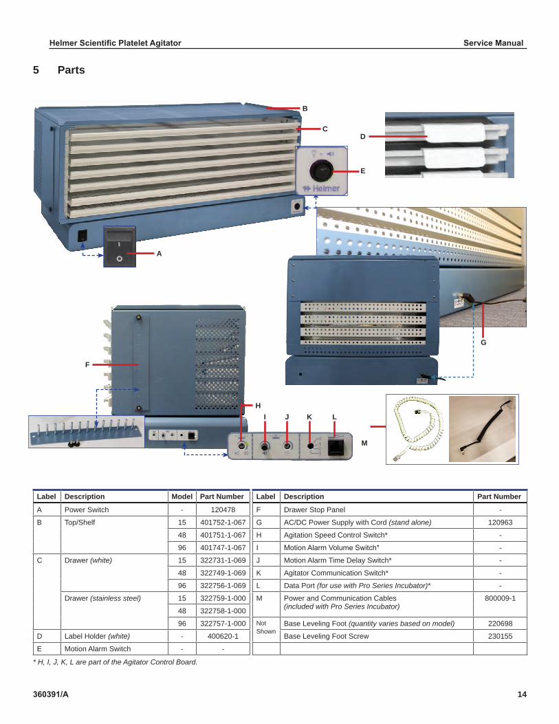
5 Parts
Label Description Model Part Number Label Description Part Number
A Power Switch - 120478 F Drawer Stop Panel -
B Top/Shelf 15 401752-1-067 G AC/DC Power Supply with Cord (stand alone) 120963
48 401751-1-067 H Agitation Speed Control Switch* -
96 401747-1-067 I MotionAlarmVolumeSwitch* -
C Drawer (white) 15 322731-1-069 J Motion Alarm Time Delay Switch* -
48 322749-1-069 K Agitator Communication Switch* -
96 322756-1-069 L Data Port (for use with Pro Series Incubator)* -
Drawer (stainless steel) 15 322759-1-000 M Power and Communication Cables (included with Pro Series Incubator)
800009-1
48 322758-1-000
96 322757-1-000 Not Shown
Base Leveling Foot (quantity varies based on model) 220698
D Label Holder (white) - 400620-1 Base Leveling Foot Screw 230155
E Motion Alarm Switch - -
* H, I, J, K, L are part of the Agitator Control Board.
G
L
G
A
M
KJIH
D
E
C
F
B
L
Helmer Scientific Platelet Agitator Service Manual
360391/A 15
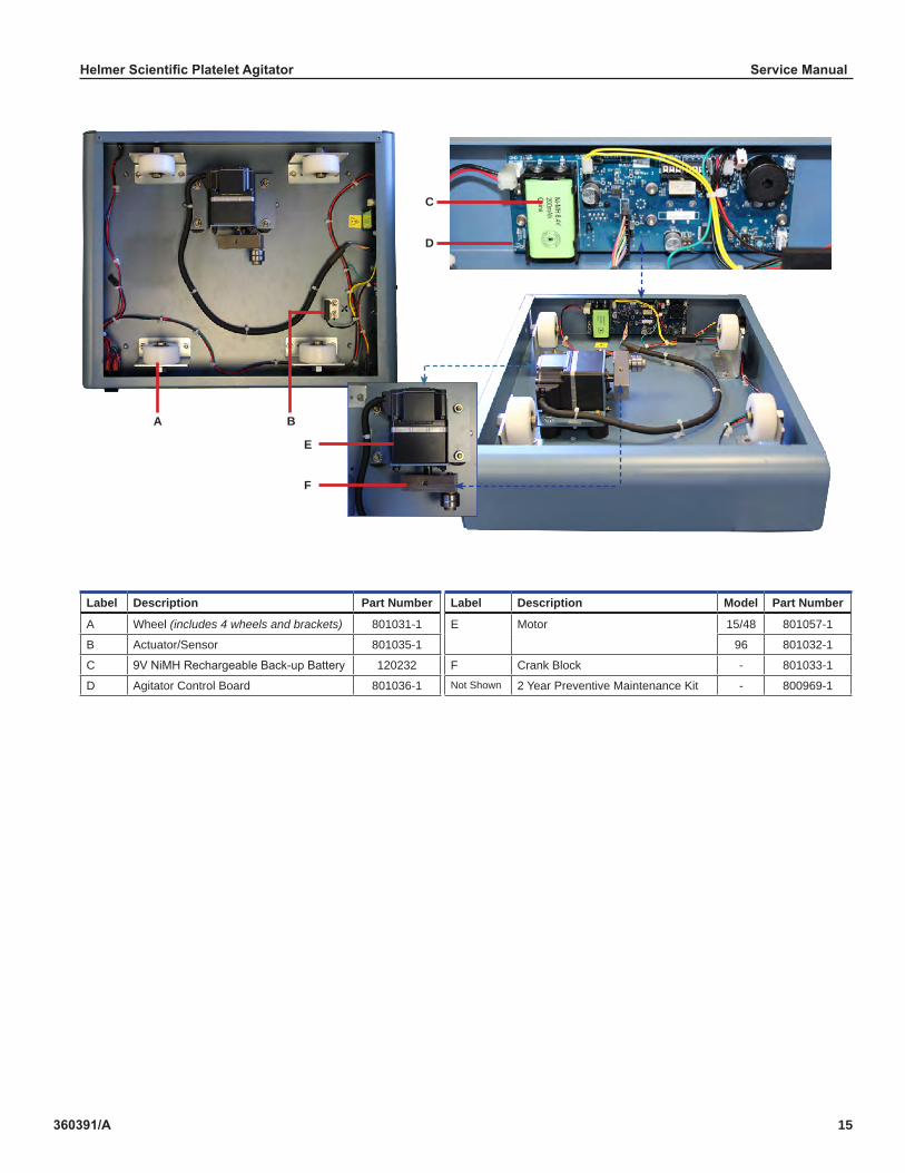
Label Description Part Number Label Description Model Part Number
A Wheel (includes 4 wheels and brackets) 801031-1 E Motor 15/48 801057-1
B Actuator/Sensor 801035-1 96 801032-1
C 9VNiMHRechargeableBack-upBattery 120232 F Crank Block - 801033-1
D Agitator Control Board 801036-1 Not Shown 2 Year Preventive Maintenance Kit - 800969-1
A
F
E
D
B
C
Helmer Scientific Platelet Agitator Service Manual
360391/A 16
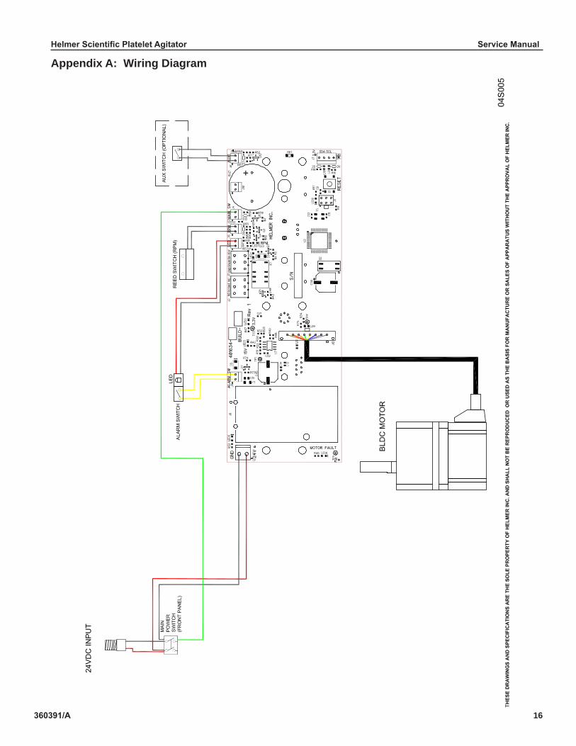
Appendix A: Wiring Diagram

Helmer Scientific Platelet Agitator Service Manual
360391/A 17
Appendix B: WarrantyFor technical service needs, please contact Helmer at 800-743-5637 or www.helmerinc.com. Have the model and serial number available when calling.
Rapid ResolutionWhen a warranty issue arises it is our desire to respond quickly and appropriately. The service department at Helmer is there foryou.Helmerwilloverseethehandlingofyourwarrantyservicefromstarttofinish.Therefore,Helmermustgiveadvanceauthorization for all service calls and/or parts needs relating to a warranty issue. Any repeat service calls must also be authorized as well. This allows for proper diagnosis and action. Helmer will not be responsible for charges incurred for service calls made by thirdpartiespriortoauthorizationfromHelmer.Helmerretainstherighttoreplaceanyproductinlieuofservicingitinthefield.
PartsForaperiodoftwo(2)years,Helmerwillsupplyatnocharge,includingfreight,anypartthatfailsduetodefectsinmaterialorworkmanship under normal use, with the exception of expendable items. Batteries are expendable items. Inspection of defective partsbyHelmerwillbefinalindeterminingwarrantystatus.Warrantyproceduresmustbefollowedinallevents.
LaborForaperiodofone(1)year,Helmerwillcoverrepairlaborcosts,providedthattheproductisreturnedtoHelmerforwarrantyservice.Alternatively,yourfacility’sstaffmayworkwithaHelmertechniciantomakerepairsonsite.Laborcostsforrepairsperformed at a location other than Helmer, or for repairs made without the assistance of a Helmer technician, will be the responsibility of the end user.
Additional Warranty InformationThe time periods set forth above begin two weeks after the original date of shipment from Helmer. Warranty procedures set forth above must be followed in all events.
THEREARENOWARRANTIESWHICHEXTENDBEYONDTHEDESCRIPTIONONTHEFACEHEREOF.THISWARRANTYISEXCLUSIVEANDINLIEUOFALLOTHERWARRANTIES,EXPRESSORIMPLIED,INCLUDINGWITHOUTLIMITATIONANYWARRANTYOFMERCHANTABILITYORFITNESSFORAPARTICULARPURPOSE.NOWARRANTIESOFMERCHANTABILITYORFITNESSFORPARTICULARPURPOSESHALLAPPLY.THELIABILITY,IFANY,OFHELMERFORDIRECTDAMAGESWHETHERARISINGFROMABREACHOFANYSALESAGREEMENT,BREACHOFWARRANTY,NEGLIGENCE,ORINDEMNITY,STRICTLIABILITYOROTHERTORT,OROTHERWISEWITHRESPECTTOTHEGOODSORANYSERVICESISLIMITEDTOANAMOUNTNOTTOEXCEEDTHEPRICEOFTHEPARTICULARGOODSORSERVICESGIVINGRISETOTHELIABILITY.INNOEVENTSHALLHELMERBELIABLEFORANYINDIRECT,INCIDENTAL,CONSEQUENTIAL,ORSPECIALDAMAGES,INCLUDINGWITHOUTLIMITATIONDAMAGESRELATEDTOLOSTREVENUESORPROFITS,ORLOSSOFPRODUCTS.
Thiswarrantydoesnotcoverdamagescausedintransit,duringinstallationbyaccident,misuse,fire,flood,oractsofGod.Further,this warranty will not be valid if Helmer determines that the failure was caused by a lack of performing recommended equipment maintenance(perHelmermanual)orbyusingtheproductinamannerotherthanforitsintendeduse.Installationandcalibrationare not covered under this warranty agreement.
Outside of USA and CanadaConsult your local distributor for warranty information.

Helmer Scientific Platelet Agitator Service Manual
360391/A 18

Helmer Scientific14400 Bergen Boulevard, Noblesville, IN 46060 USA
Copyright © 2019 Helmer, Inc. 360391/A