
Platelet Incubator Service Manual - Helmer Scientific...Decontaminate parts prior to sending for...
39
360389/A Platelet Incubator Service Manual i.Series ® -Pro Models Countertop PC100-Pro PC900-Pro PC1200-Pro
Transcript of Platelet Incubator Service Manual - Helmer Scientific...Decontaminate parts prior to sending for...

360389/A
Platelet Incubator Service Manuali.Series® -Pro Models
CountertopPC100-Pro PC900-Pro PC1200-Pro

Document Updates The document is furnished for information use only, is subject to change without notice and should not be construed as a commitment by Helmer Scientific. Helmer Scientific assumes no responsibility or liability for any errors or inaccuracies that may appear in the informational content contained in this material. For the purpose of clarity, Helmer Scientific considers only the most recent revision of this document to be valid.
Notices and DisclaimersConfidential / Proprietary NoticesUse of any portion(s) of this document to copy, translate, disassemble or decompile, or create or attempt to create by reverse engineering or otherwise the information from Helmer Scientific products is expressly prohibited.
Copyright and TrademarkHelmer®, i.Series®, i.Center®, i.C3
®, AgiTrak™, and Rel.i™ are registered trademarks or trademarks of Helmer, Inc. in the United States of America. Copyright © 2019 Helmer, Inc. All other trademarks and registered trademarks are the property of their respective owners.Helmer, Inc., doing business as (DBA) Helmer Scientific and Helmer.
DisclaimerThis manual is intended as a guide to provide the operator with necessary instructions on the proper use and maintenance of certain Helmer Scientific products.Any failure to follow the instructions as described could result in impaired product function, injury to the operator or others, or void applicable product warranties. Helmer Scientific accepts no responsibility for liability resulting from improper use or maintenance of its products.The screenshots and component images appearing in this guide are provided for illustrative purposes only, and may vary slightly from the actual software screens and/or product components.
Helmer Scientific14400 Bergen BoulevardNoblesville, IN 46060 USAwww.helmerinc.com Part No. 360389/ Rev A
Document HistoryRevision Date CO Supersession Revision DescriptionA 5 JUL 2019 14829 N/A Initial Release
* Date submitted for Change Order review. Actual release date may vary.
Helmer Scientific Platelet Incubator Pro Service Manual
360389/A ii
Contents1 About this Manual . . . . . . . . . . . . . . . . . . . . . . . . . . . . . . . . . . . . . . . . . . . . . . . . . . . . . . . . . . . . . . . . . . . . . . . . . . . . . . . . . . . . . . . . . . . . . . . . 3
1.1 Intended Audience . . . . . . . . . . . . . . . . . . . . . . . . . . . . . . . . . . . . . . . . . . . . . . . . . . . . . . . . . . . . . . . . . . . . . . . . . . . . . . . . . . . . . . . . . . 31.2 Model Reference . . . . . . . . . . . . . . . . . . . . . . . . . . . . . . . . . . . . . . . . . . . . . . . . . . . . . . . . . . . . . . . . . . . . . . . . . . . . . . . . . . . . . . . . . . . . 31.3 Intended Use . . . . . . . . . . . . . . . . . . . . . . . . . . . . . . . . . . . . . . . . . . . . . . . . . . . . . . . . . . . . . . . . . . . . . . . . . . . . . . . . . . . . . . . . . . . . . . . 31.4 Safety Symbols and Precautions . . . . . . . . . . . . . . . . . . . . . . . . . . . . . . . . . . . . . . . . . . . . . . . . . . . . . . . . . . . . . . . . . . . . . . . . . . . . . . . 31.5 Avoiding Injury . . . . . . . . . . . . . . . . . . . . . . . . . . . . . . . . . . . . . . . . . . . . . . . . . . . . . . . . . . . . . . . . . . . . . . . . . . . . . . . . . . . . . . . . . . . . . . 41.6 Product Labels . . . . . . . . . . . . . . . . . . . . . . . . . . . . . . . . . . . . . . . . . . . . . . . . . . . . . . . . . . . . . . . . . . . . . . . . . . . . . . . . . . . . . . . . . . . . . 5
2 InstallationandConfiguration . . . . . . . . . . . . . . . . . . . . . . . . . . . . . . . . . . . . . . . . . . . . . . . . . . . . . . . . . . . . . . . . . . . . . . . . . . . . . . . . . . . . . . 62.1 Location Requirements . . . . . . . . . . . . . . . . . . . . . . . . . . . . . . . . . . . . . . . . . . . . . . . . . . . . . . . . . . . . . . . . . . . . . . . . . . . . . . . . . . . . . . . 62.2 Placement and Leveling . . . . . . . . . . . . . . . . . . . . . . . . . . . . . . . . . . . . . . . . . . . . . . . . . . . . . . . . . . . . . . . . . . . . . . . . . . . . . . . . . . . . . . 62.3 Connect Back-Up Power . . . . . . . . . . . . . . . . . . . . . . . . . . . . . . . . . . . . . . . . . . . . . . . . . . . . . . . . . . . . . . . . . . . . . . . . . . . . . . . . . . . . . . 62.4 Platelet Agitator and Platelet Incubator Compatibility . . . . . . . . . . . . . . . . . . . . . . . . . . . . . . . . . . . . . . . . . . . . . . . . . . . . . . . . . . . . . . . . 72.5 Install Pro Series Platelet Agitator (Optional) . . . . . . . . . . . . . . . . . . . . . . . . . . . . . . . . . . . . . . . . . . . . . . . . . . . . . . . . . . . . . . . . . . . . . . 72.6 Temperature Probes . . . . . . . . . . . . . . . . . . . . . . . . . . . . . . . . . . . . . . . . . . . . . . . . . . . . . . . . . . . . . . . . . . . . . . . . . . . . . . . . . . . . . . . . . 82.7 Chart Recorder . . . . . . . . . . . . . . . . . . . . . . . . . . . . . . . . . . . . . . . . . . . . . . . . . . . . . . . . . . . . . . . . . . . . . . . . . . . . . . . . . . . . . . . . . . . . . 92.8 External Monitoring Devices . . . . . . . . . . . . . . . . . . . . . . . . . . . . . . . . . . . . . . . . . . . . . . . . . . . . . . . . . . . . . . . . . . . . . . . . . . . . . . . . . . 10
3 Controls . . . . . . . . . . . . . . . . . . . . . . . . . . . . . . . . . . . . . . . . . . . . . . . . . . . . . . . . . . . . . . . . . . . . . . . . . . . . . . . . . . . . . . . . . . . . . . . . . . . . . . . .113.1 Home Screen and Screensaver . . . . . . . . . . . . . . . . . . . . . . . . . . . . . . . . . . . . . . . . . . . . . . . . . . . . . . . . . . . . . . . . . . . . . . . . . . . . . . . .113.2 Home Screen Functions . . . . . . . . . . . . . . . . . . . . . . . . . . . . . . . . . . . . . . . . . . . . . . . . . . . . . . . . . . . . . . . . . . . . . . . . . . . . . . . . . . . . . .113.3 Event Log . . . . . . . . . . . . . . . . . . . . . . . . . . . . . . . . . . . . . . . . . . . . . . . . . . . . . . . . . . . . . . . . . . . . . . . . . . . . . . . . . . . . . . . . . . . . . . . . 123.4 Alarm Reference . . . . . . . . . . . . . . . . . . . . . . . . . . . . . . . . . . . . . . . . . . . . . . . . . . . . . . . . . . . . . . . . . . . . . . . . . . . . . . . . . . . . . . . . . . . 133.5 Settings . . . . . . . . . . . . . . . . . . . . . . . . . . . . . . . . . . . . . . . . . . . . . . . . . . . . . . . . . . . . . . . . . . . . . . . . . . . . . . . . . . . . . . . . . . . . . . . . . . 143.6 Sensor Calibration . . . . . . . . . . . . . . . . . . . . . . . . . . . . . . . . . . . . . . . . . . . . . . . . . . . . . . . . . . . . . . . . . . . . . . . . . . . . . . . . . . . . . . . . . . 173.7 AgiTrak™ System . . . . . . . . . . . . . . . . . . . . . . . . . . . . . . . . . . . . . . . . . . . . . . . . . . . . . . . . . . . . . . . . . . . . . . . . . . . . . . . . . . . . . . . . . . 20
4 Maintenance . . . . . . . . . . . . . . . . . . . . . . . . . . . . . . . . . . . . . . . . . . . . . . . . . . . . . . . . . . . . . . . . . . . . . . . . . . . . . . . . . . . . . . . . . . . . . . . . . . . . 214.1 Alarm Tests . . . . . . . . . . . . . . . . . . . . . . . . . . . . . . . . . . . . . . . . . . . . . . . . . . . . . . . . . . . . . . . . . . . . . . . . . . . . . . . . . . . . . . . . . . . . . . . 224.2 Test and Replace Back-up Battery . . . . . . . . . . . . . . . . . . . . . . . . . . . . . . . . . . . . . . . . . . . . . . . . . . . . . . . . . . . . . . . . . . . . . . . . . . . . . 254.4 Upgrade System Firmware . . . . . . . . . . . . . . . . . . . . . . . . . . . . . . . . . . . . . . . . . . . . . . . . . . . . . . . . . . . . . . . . . . . . . . . . . . . . . . . . . . . 274.5 Clean the Platelet Incubator . . . . . . . . . . . . . . . . . . . . . . . . . . . . . . . . . . . . . . . . . . . . . . . . . . . . . . . . . . . . . . . . . . . . . . . . . . . . . . . . . . 27
5 Service . . . . . . . . . . . . . . . . . . . . . . . . . . . . . . . . . . . . . . . . . . . . . . . . . . . . . . . . . . . . . . . . . . . . . . . . . . . . . . . . . . . . . . . . . . . . . . . . . . . . . . . . 285.1 Condensate Tray . . . . . . . . . . . . . . . . . . . . . . . . . . . . . . . . . . . . . . . . . . . . . . . . . . . . . . . . . . . . . . . . . . . . . . . . . . . . . . . . . . . . . . . . . . . 285.2 CSV Download . . . . . . . . . . . . . . . . . . . . . . . . . . . . . . . . . . . . . . . . . . . . . . . . . . . . . . . . . . . . . . . . . . . . . . . . . . . . . . . . . . . . . . . . . . . . 28
6 Troubleshooting . . . . . . . . . . . . . . . . . . . . . . . . . . . . . . . . . . . . . . . . . . . . . . . . . . . . . . . . . . . . . . . . . . . . . . . . . . . . . . . . . . . . . . . . . . . . . . . . 306.1 General Operation Problems . . . . . . . . . . . . . . . . . . . . . . . . . . . . . . . . . . . . . . . . . . . . . . . . . . . . . . . . . . . . . . . . . . . . . . . . . . . . . . . . . 306.2 Chamber Temperature Problems . . . . . . . . . . . . . . . . . . . . . . . . . . . . . . . . . . . . . . . . . . . . . . . . . . . . . . . . . . . . . . . . . . . . . . . . . . . . . . 316.3 Alarm Activation Problems . . . . . . . . . . . . . . . . . . . . . . . . . . . . . . . . . . . . . . . . . . . . . . . . . . . . . . . . . . . . . . . . . . . . . . . . . . . . . . . . . . . 31
7 Parts . . . . . . . . . . . . . . . . . . . . . . . . . . . . . . . . . . . . . . . . . . . . . . . . . . . . . . . . . . . . . . . . . . . . . . . . . . . . . . . . . . . . . . . . . . . . . . . . . . . . . . . . . . 32
8 Schematics . . . . . . . . . . . . . . . . . . . . . . . . . . . . . . . . . . . . . . . . . . . . . . . . . . . . . . . . . . . . . . . . . . . . . . . . . . . . . . . . . . . . . . . . . . . . . . . . . . . . 348.1 PC100-Pro, PC900-Pro, PC1200-Pro . . . . . . . . . . . . . . . . . . . . . . . . . . . . . . . . . . . . . . . . . . . . . . . . . . . . . . . . . . . . . . . . . . . . . . . . . . . 34
Appendix A: Warranty . . . . . . . . . . . . . . . . . . . . . . . . . . . . . . . . . . . . . . . . . . . . . . . . . . . . . . . . . . . . . . . . . . . . . . . . . . . . . . . . . . . . . . . . . . . . . . . 37

Helmer Scientific Platelet Incubator Pro Service Manual
360389/A 3
1 About this Manual1.1 Intended AudienceThis manual provides information on how to use the platelet incubator Pro. It is intended for use by end users of the platelet incubator and authorized service technicians.
1.2 Model ReferenceThis manual covers all Pro Series platelet incubators which may be identified by size or model number.
1.3 Intended Use Note
This equipment has been tested and found to comply with the limits for a Class A digital device, pursuant to part 15 of the FCC Rules. These limits are designed to provide reasonable protection against harmful interference when the equipment is operated in a commercial environment. This equipment generates, uses and can radiate radio frequency energy and, if not installed and used in accordance with the instruction manual, may cause harmful interference to radio communications. Operation of this equipment in a residential area is likely to cause harmful interference in which case the user will be required to correct the interference at his own expense.
Helmer platelet incubators are intended to provide the controlled temperature environment required for the storage of platelet products.The devices are intended to be operated by personnel who have procedures in place for meeting FDA, AABB, EU or any other applicable regulations for the processing and storage of platelet products.
1.4 Safety Symbols and Precautions
Symbols and precautions found in this document
The following symbols are used in this manual to emphasize certain details for the user:
Task Indicates procedures which need to be followed.
Note Provides useful information regarding a procedure or operating technique when using Helmer Scientific products.
NOTICE Advises the user against initiating an action or creating a situation which could result in damage to equipment; personal injury is unlikely.
CAUTION Advises the user against initiating an action or creating a situation which could result in damage to equipment or impair the quality of the products or cause minor injury.WARNING Advises the user against initiating an action or creating a situation which could result in damage to equipment and serious personal injury to a patient or the user. Authorized representative in the European CommunityEC REP

Helmer Scientific Platelet Incubator Pro Service Manual
360389/A 4
Symbols found on the units
The following symbols may be found on the refrigerator or refrigerator packaging:
0086
CE Mark (European units only)Earth / ground terminal
Caution: Risk of damage to equipment or danger to operator Protective earth / ground terminal
Caution: Hot surface Product falls under the scope of the WEEE (Waste Electrical and Electronic Equipment)directive.
Caution: Shock / electrical hazard
1.5 AvoidingInjury
Review safety instructions before installing, using, or maintaining the equipment. ♦ Before moving unit, remove the installed agitator (if applicable). ♦ Before moving unit, ensure door is closed. ♦ Before moving unit, disconnect the AC power cord and secure the cord. ♦ When moving unit, use assistance from a second person. ♦ Never physically restrict any moving component. ♦ Avoid removing electrical service panels and access panels unless so instructed. ♦ Do not store or place objects or liquid containers on top of the incubator. ♦ Keep hands away from pinch points when closing the door or when agitation motion is enabled (if applicable). ♦ Avoid sharp edges when working inside the electrical compartment. ♦ Ensure biological materials are stored at recommended temperatures determined by standards, literature, or good
laboratory practices. ♦ Proceed with caution when adding and removing product from the platelet incubator. ♦ Use manufacturer supplied power cord only. ♦ Using the equipment in a manner not specified by Helmer Scientific may impair the protection provided by the equipment. ♦ The platelet incubator is not considered to be a storage cabinet for flammable or hazardous materials.
CAUTIONDecontaminate parts prior to sending for service or repair. Contact Helmer Scientific or your distributor for decontamination instructions and a Return Authorization Number.
Helmer Scientific Platelet Incubator Pro Service Manual
360389/A 5
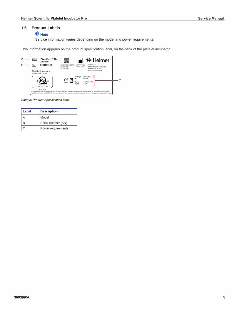
1.6 Product Labels Note
Service information varies depending on the model and power requirements.
This information appears on the product specification label, on the back of the platelet incubator.
REF
SN
PC100-PROi.Series®
1000000
Voltage 100-240V a.c.HZ 50/60
Power 352W/415WFuse 7.0A
Platelet IncubatorWeight 116 lb / 62 kg
Helmer, Inc.14400 Bergen BoulevardNoblesville, IN USAwww.helmerinc.com
2019-03-28Made in USA
(01)00816394020940(11)190328(21)2061931
0086
This device complies with Part 15 of the FCC rules. Operation is subject to the following two conditions: (1) This device may not cause harmful interference, and (2) This device must accept any interference received, including interference that may cause undesired operation.
CB1095
CertifiedUL 61010-1/CSA 61010-1
UR
C
A
B
Sample Product Specification label.
Label Description
A Model
B Serial number (SN)
C Power requirements

Helmer Scientific Platelet Incubator Pro Service Manual
360389/A 6
2 InstallationandConfiguration2.1 Location Requirements
NoteHot ambient temperatures with high humidity may cause condensation on the outside of the unit.
♦ Has a sturdy, level surface. ♦ Has a grounded outlet meeting national electric code (NEC) and local electrical requirements. ♦ Is clear of direct sunlight, high temperature sources, and heating and air conditioning vents. ♦ Meets limits specified for ambient temperature (15 °C to 35 °C) and relative humidity. ♦ Minimum 24” (610 mm) above for ambient temperatures of 28 °C to 35 °C. ♦ Minimum 4” (102 mm) above for ambient temperatures of 15 °C to 28 °C. ♦ Minimum 12” (305 mm) behind for ambient temperatures of 28 °C to 35 °C. ♦ Minimum 4” (102 mm) behind for ambient temperatures of 15 °C to 28 °C.
2.2 PlacementandLeveling
NoteRear stand-off brackets are provided with the unit and should be installed prior to placing the incubator in its location.
1. Align keyhole openings in stand-off bracket with screws on back of incubator and slide down to engage. 2. Tighten screws using a #2 Phillips screwdriver to secure. 3. Place platelet incubator on sturdy surface.4. Ensure platelet incubator is level.
2.3 Connect Back-Up PowerThe monitoring and alarm system, and chart recorder each have a back-up battery, enabling a period of continuous operation if power is lost.The PC100-Pro has an optional additional full system back-up battery enabling a period of continuous operation of the incubator and agitator if power is lost.Battery life varies by manufacturer as well as voltage level remaining. The battery must have 48 consecutive hours of power to be fully charged. Providing full power is available and no battery-related alarms are active, back-up power for the monitoring system is available for up to 18 hours.The batteries are located on the top of the platelet incubator, under a removable access panel.The back-up battery switch is OFF for shipping. Turn the back-up battery switch ON to provide the monitoring system with back-up power in the event of AC power failure.
Notes• The monitoring system will start on battery power alone. If the platelet incubator was previously not connected to AC power and the batteries are connected, the monitoring system will begin running on battery power.• If AC power is lost, the monitoring system will continue to collect data until battery power is depleted.• Use only a 12V 7AHr SLA battery for the standard monitoring and alarm system battery back-up.• Use only a 12V 18AHr SLA battery (quantity 2) for the PC100-Pro integrated full system battery back-up.
CAUTIONBefore installing or replacing batteries, switch the main power switch to OFF and the back-up battery switch to OFF. Disconnect the power cord from the power receptacle.
Rear Stand-off Bracket
Helmer Scientific Platelet Incubator Pro Service Manual
360389/A 7
2.4 PlateletAgitatorandPlateletIncubatorCompatibilityPro Series platelet incubators may only be fitted with Pro Series platelet agitators. When installed in a Pro Series platelet incubator, the Pro Series platelet agitator can be monitored by the platelet incubator’s AgiTrak™ system.The AgiTrak™ system receives alarm information through a direct connection from the platelet agitator’s alarm system to the platelet incubator’s alarm system.
NoteOnly Pro Series platelet incubators can monitor Pro Series platelet agitators.
Platelet Incubator CompatibleHelmerPlateletAgitator
PC100-Pro PF15-Pro
PC900-Pro PF48-Pro
PC1200-Pro PF96-Pro
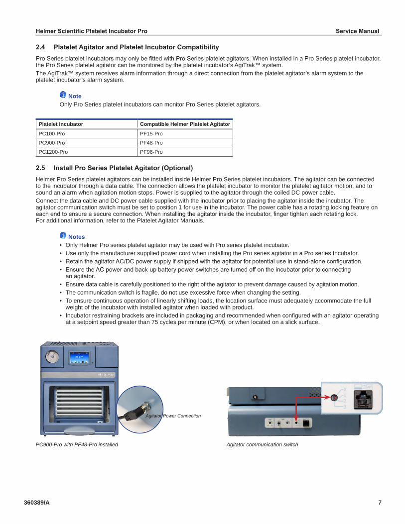
2.5 InstallProSeriesPlateletAgitator(Optional)Helmer Pro Series platelet agitators can be installed inside Helmer Pro Series platelet incubators. The agitator can be connected to the incubator through a data cable. The connection allows the platelet incubator to monitor the platelet agitator motion, and to sound an alarm when agitation motion stops. Power is supplied to the agitator through the coiled DC power cable. Connect the data cable and DC power cable supplied with the incubator prior to placing the agitator inside the incubator. The agitator communication switch must be set to position 1 for use in the incubator. The power cable has a rotating locking feature on each end to ensure a secure connection. When installing the agitator inside the incubator, finger tighten each rotating lock. For additional information, refer to the Platelet Agitator Manuals.
Notes• Only Helmer Pro series platelet agitator may be used with Pro series platelet incubator. • Use only the manufacturer supplied power cord when installing the Pro series agitator in a Pro series Incubator.• Retain the agitator AC/DC power supply if shipped with the agitator for potential use in stand-alone configuration.• Ensure the AC power and back-up battery power switches are turned off on the incubator prior to connecting an agitator.• Ensure data cable is carefully positioned to the right of the agitator to prevent damage caused by agitation motion.• The communication switch is fragile, do not use excessive force when changing the setting.• To ensure continuous operation of linearly shifting loads, the location surface must adequately accommodate the full weight of the incubator with installed agitator when loaded with product. • Incubator restraining brackets are included in packaging and recommended when configured with an agitator operating at a setpoint speed greater than 75 cycles per minute (CPM), or when located on a slick surface.
PC900-Pro with PF48-Pro installed Agitator communication switch
Agitator Power Connection

Helmer Scientific Platelet Incubator Pro Service Manual
360389/A 8
2.6 Temperature Probes
Notes• Temperature probes are fragile; handle with care.• Remote probes may also be introduced through the rear port.
The temperature monitor and control probes are located on the right side of the unit.
CAUTION• The incubator power switch and battery back-up switch must be turned OFF and the AC power cord disconnected from the power receptacle prior to installing an external probe.• DO NOT attach remote probe wires to the AC Terminal block wires or the AC power supply.
AC Power Supply
Remote probe routing path Mounting clip
Install Remote Probe1. Switch the AC power switch to OFF; switch the back-up battery switch to OFF; disconnect the power cord from the power receptacle.2. Open incubator door and locate the access port plug at the top of the chamber. Use a flat blade screwdriver to pry off the access port plug.3. Use a #2 Phillips screwdriver to remove the screws securing the top cover, and set top cover and screws aside. 4. Locate the access port on the top of the unit, and peel back the putty.5. Install the remote probe through the rear panel of the incubator, down through the hole in the top of the unit, and into the chamber.6. Attach the remote probe to the plastic mounting clip inside the chamber.7. Secure the remote probe wires to the wire bundle in the top of the unit using wire ties. 8. Reseal the top access port with putty. 9. Reinstall the top cover and secure with screws using a #2 Phillips screwdriver.10. Reconnect the power cord to the wall receptacle. Switch the main power switch to ON; switch the back-up battery switch to ON. 11. Allow the temperature to stabilize at the setpoint before moving inventory back into the incubator.

Helmer Scientific Platelet Incubator Pro Service Manual
360389/A 9
2.7 Chart Recorder Note
For complete information, refer to the Temperature Chart Recorder Operation and Service Manual.
The chart recorder has a battery system, enabling a period of continuous operation if power is lost. Battery life varies by manufacturer as well as voltage level remaining. Providing full power is available, back-up power for the temperature chart recorder is available for up to 14 hours.
Prior to use: ♦ Install battery. ♦ Add paper. ♦ Calibrate chart recorder to match upper chamber temperature.
Set up and OperationOpen the door by pressing and releasing.
Chart recorder Chart recorder (door open)
Install BatteryConnect the leads to the battery to provide back-up power to the chart recorder.
Install or Replace Chart Paper
NoteFor accurate temperature reading, ensure that current time is aligned with time line groove when chart knob is tightened.
Chart recorder stylus and time line groove
1. Press and hold C button. When stylus begins to move left, release button. The LED flashes to indicate current temperature range.2. When stylus stops moving, remove chart knob then move knob up and away.3. Place chart paper on chart recorder.4. Gently lift stylus and rotate paper so current time line corresponds to time line groove.5. Hold chart paper in place while making sure the chart knob is fully tightened. (Failure to fully tighten the knob can result in paper slipping and losing time.)
6. Confirm temperature range is set to the correct value.7. Press and hold C button. When stylus begins to move right, release button.8. Confirm stylus is marking temperature correctly.

Helmer Scientific Platelet Incubator Pro Service Manual
360389/A 10
2.8 ExternalMonitoringDevicesThe remote alarm interface is a relay switch with three terminals:
♦ Common (COM) ♦ Normally Open (NO) ♦ Normally Closed (NC)
Terminals are dry contacts and do not supply voltage. Interface circuit is either normally open or normally closed, depending on terminals used.Requirements for your alarm system determine which alarm wires must connect to terminals.
CAUTION• The interface on the remote alarm monitoring system is intended for connection to the end user’s central alarm system(s) that uses normally-open or normally-closed dry contacts.• If an external power supply exceeding 33V (AC) RMS or 30V (DC) is connected to the remote alarm monitoring system’s circuit, the remote alarm will not function properly; may be damaged; or may result in injury to the user.
NOTICEFor any platelet incubator without a platelet agitator installed, a bypass plug (PN 402149-1) is needed for a normally- closed interface circuit.
The terminals on the remote alarm interface have the following maximum load capacity: ♦ 1A at 33V (AC) RMS or 30V (DC)
Connect to Remote Alarm Interface1. Switch the Battery ON/OFF key switch OFF. Switch the AC ON/OFF switch OFF.2. On the alarm panel, locate the remote alarm terminals.3. Connect remote alarm wires to appropriate terminals, according to requirements for your alarm system.4. Use a cable tie to relieve strain on alarm wires (as necessary).5. Switch the Battery ON/OFF switch ON. Switch the AC ON/OFF switch ON. 6. Touch MUTE to disable the high temperature alarm while platelet incubator reaches operating temperature.
Remote alarm interface.

Helmer Scientific Platelet Incubator Pro Service Manual
360389/A 11
3 Controlsi.Series -Pro platelet incubators are equipped with the i.C3 monitoring and control system. The i.C3 system combines temperature control and monitoring into a single user interface.
NotePlease refer to the i.C3 User Guide for complete information regarding the i.C3 User Interface.
3.1 Home Screen and ScreensaverThe Home Screen is the default screen and is displayed when:
♦ The Home icon is touched from any other screen ♦ There is no interaction for two minutes on any screen other than those used to enter a password.
Home Screen Screensaver
3.2 Home Screen Functions
NoteRefer to the i.C3 User Guide for options available on all i.C3 screens.
♦ View current interior temperature readings ♦ View current system time and date ♦ Access any of five home screen applications (touch i.C³ APPS for additional applications) ♦ View information about current alarm events ♦ View whether the monitoring system is running on battery power ♦ Mute audible alarms ♦ View a graph of the interior temperature ♦ View unit ID ♦ Shortcut to Event Log

Helmer Scientific Platelet Incubator Pro Service Manual
360389/A 12
3.3 EventLog
Event Log screen Event Log Detail screen
ViewEventLogDetail1. From the Home screen, touch the EventLog icon. The Event Log screen appears.2. Touch an Event. The Event Log Detail screen appears3. Select the Back arrow to return to the previous screen or the Home icon to return to the Home screen.
AcknowledgeanEvent1. From the Home screen, touch the EventLog icon. The Event Log screen appears.2. Touch an Event. The Event Log Detail screen appears3. Touch the Event Cause button at the bottom of the screen. A possible cause menu appears.4. Select the appropriate cause for the event or select Other and use the alphanumeric keyboard to make an entry.5. Touch the Action Taken button at the bottom of the screen. A possible actions menu appears.6. Select the appropriate action taken or select Other and use the alphanumeric keyboard to make an entry.7. Touch the Signature button at the bottom of the screen. An alphanumeric keyboard appears.8. Enter your signature. 9. Touch to save or to cancel.
Helmer Scientific Platelet Incubator Pro Service Manual
360389/A 13
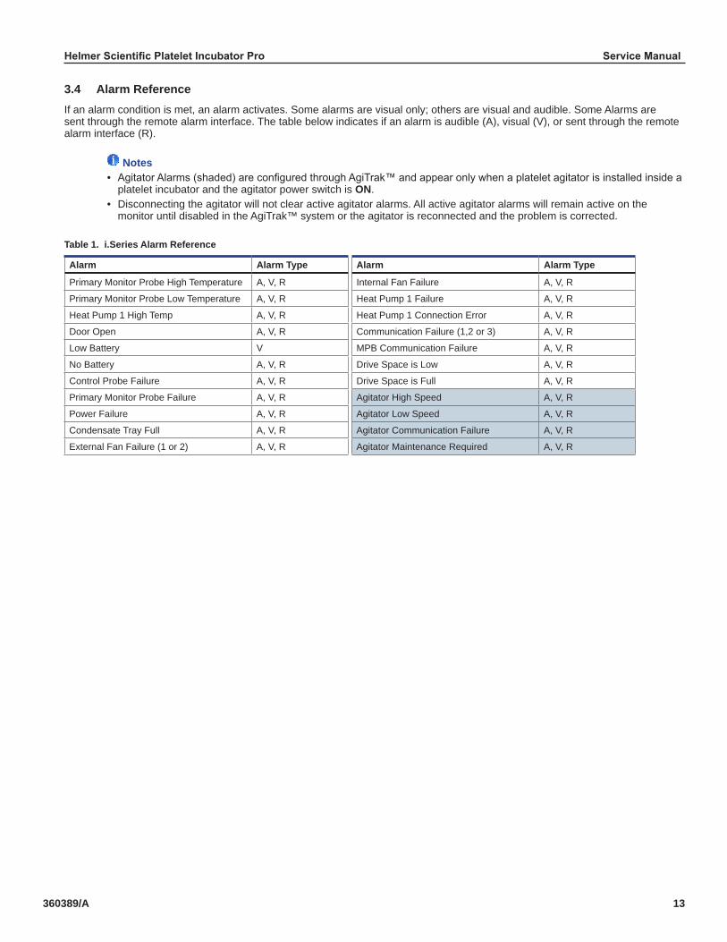
3.4 Alarm ReferenceIf an alarm condition is met, an alarm activates. Some alarms are visual only; others are visual and audible. Some Alarms are sent through the remote alarm interface. The table below indicates if an alarm is audible (A), visual (V), or sent through the remote alarm interface (R).
Notes• Agitator Alarms (shaded) are configured through AgiTrak™ and appear only when a platelet agitator is installed inside a platelet incubator and the agitator power switch is ON.• Disconnecting the agitator will not clear active agitator alarms. All active agitator alarms will remain active on the monitor until disabled in the AgiTrak™ system or the agitator is reconnected and the problem is corrected.
Table 1. i.Series Alarm Reference
Alarm Alarm Type Alarm Alarm Type
Primary Monitor Probe High Temperature A, V, R Internal Fan Failure A, V, R
Primary Monitor Probe Low Temperature A, V, R Heat Pump 1 Failure A, V, R
Heat Pump 1 High Temp A, V, R Heat Pump 1 Connection Error A, V, R
Door Open A, V, R Communication Failure (1,2 or 3) A, V, R
Low Battery V MPB Communication Failure A, V, R
No Battery A, V, R Drive Space is Low A, V, R
Control Probe Failure A, V, R Drive Space is Full A, V, R
Primary Monitor Probe Failure A, V, R Agitator High Speed A, V, R
Power Failure A, V, R Agitator Low Speed A, V, R
Condensate Tray Full A, V, R Agitator Communication Failure A, V, R
External Fan Failure (1 or 2) A, V, R Agitator Maintenance Required A, V, R

Helmer Scientific Platelet Incubator Pro Service Manual
360389/A 14
3.5 Settings
> Through the i.C3 monitoring and control system, current settings may be viewed and changed. To view settings, touch i.C3 APPS, Settings. Use a touch-drag motion to scroll up or down to select the desired setting.
Settings screen
Notes• If the Settings screen is password protected, enter the appropriate password. If viewing settings for the first time, enter the factory default password of “1234”.• Default values for general settings, alarm settings, and display settings are available in the i.C3 User Guide.• Changing temperature settings affects operation of the incubator. Do not change settings unless instructed in product documentation or by Helmer Technical Service.
The i.C3 temperature and controller is programmed at the factory. To change a setting, first enter the Settings screen, then select the setting. The method for accessing the Settings mode for each setting varies.
Temperature SetpointThe setpoint is the temperature at which the incubator operates. The factory default setting for the primary monitor probe is 22.0 °C.
ChangeTemperatureSetpoint1. Touch i.C³ APPS, Settings.2. Enter the Settings password (default password is “1234”).3. Touch minus (–) or plus (+) on the Temperature Setpoint spin box to select the desired value.

Helmer Scientific Platelet Incubator Pro Service Manual
360389/A 15
UserConfigurableAlarmSettingsThe following alarm settings may be changed by the operator. The setpoint for temperature alarms may be changed (where applicable), as well as the time delay between when the alarm condition commences and when the visual and audible alarms are initiated.
NoteAgitator Alarms (shaded) are configured through AgiTrak™ and appear only when a platelet agitator is installed inside a platelet incubator and the agitator power switch is ON.
Table2.UserConfigurableAlarms
Alarm Description DefaultSetting Default Time Delay
Primary Monitor Probe High Temp High temperature at which alarm condition occurs 24 °C 0 minutes
Primary Monitor Probe Low Temp Low temperature at which alarm condition occurs 20 °C 0 minutes
Power Failure Time after power failure occurs until alarm sounds - 1 minute
Probe Failure Time after probe failure occurs until alarm sounds - 0 minutes
Door Open (Time) Time door remains open until alarm sounds - 3 minutes
Heat Pump 1 High Temp High temperature at which alarm condition occurs 50 °C 1 minute
Agitator High Speed High speed at which alarm condition occurs 75 CPM 1 minute
Agitator Low Speed Low speed at which alarm condition occurs 65 CPM 1 minute
Alarm Settings screens
ChangeAlarmSetting1. Touch i.C3 APPS, Settings.2. Enter the Settings password (default password is “1234”).3. Touch AlarmSettings.4. Touch minus (-) or plus (+) on the spin box corresponding to the alarm setting to be changed.5. Touch Home to exit the Alarm Settings screen.

Helmer Scientific Platelet Incubator Pro Service Manual
360389/A 16
Non-ConfigurableAlarmsThe following alarms indicate operation conditions which require the attention of the operator or a qualified service technician.
NoteAgitator Alarms (shaded) are configured through AgiTrak™ and appear only when a platelet agitator is installed inside a platelet incubator and the agitator alarm switch is ON.
Table3.UserNon-ConfigurableAlarms
Alarm Description
Agitator Communication Failure Occurs if Agitator Alarm Monitoring Enabled is set to YES in the Agitator Setup screen and the Incubator cannot communicate with that agitator
Agitator Maintenance Required • Occurs if Agitator Alarm Monitoring Enabled is set to YES in the Agitator Setup screen and the cycle count for that agitator reaches 75,686,400 counts (the approximate number of cycles when operating at 72 CPM over a 2 year period)• Resetting the count in the Agitator Status screen clears the alarm
Communication Failure Communication Failure 1• Triggered if communication is lost between i.C³ display board and control board.• Unit will continue to run with previously saved settings• Screen will not display temperature changes or alarm conditions• i.C³ system will continue to reset until connection is re-establishedCommunication Failure 2• Triggered if communication is lost between i.C³ display board and internal system memory• Unit will continue to run with previously saved settingsCommunication Failure 3• Triggered if the database is corrupted• The database is archived and a new database is automatically created• Unit will continue to run with previously saved settings
Condensate Tray Full Triggered when condensate tray is full of water.
Drive Space Low • Triggered if SD card containing downloadable historical date is approaching capacity• New data will continue to be saved for up to 3 more months• Data can be downloaded, but doing so will not free up capacity (SD card replacement recommended)
Drive Space Full • Triggered if the SD card containing downloadable historical data has reached its capacity• No new data will be saved• Data can be downloaded, but doing so will not free up capacity (SD card replacement required)
External Fan Failure Triggered when an external fan speed drops below the acceptable low speed limit
Internal Fan Failure Triggered when the internal fan has fallen below the acceptable low speed limit
Heat Pump Failure Triggered when electrical reading indicate the heat pump is not heating/cooling properly
Heat Pump Connection Error Triggered when temperature readings indicate the heat pump is not heating/cooling properly
Low Battery Triggered when monitoring system rechargeable battery voltage is low
MPB Communication Failure Triggered when the i.C³ is not able to communicate with the Incubator specific Master Power Board.
Helmer Scientific Platelet Incubator Pro Service Manual
360389/A 17
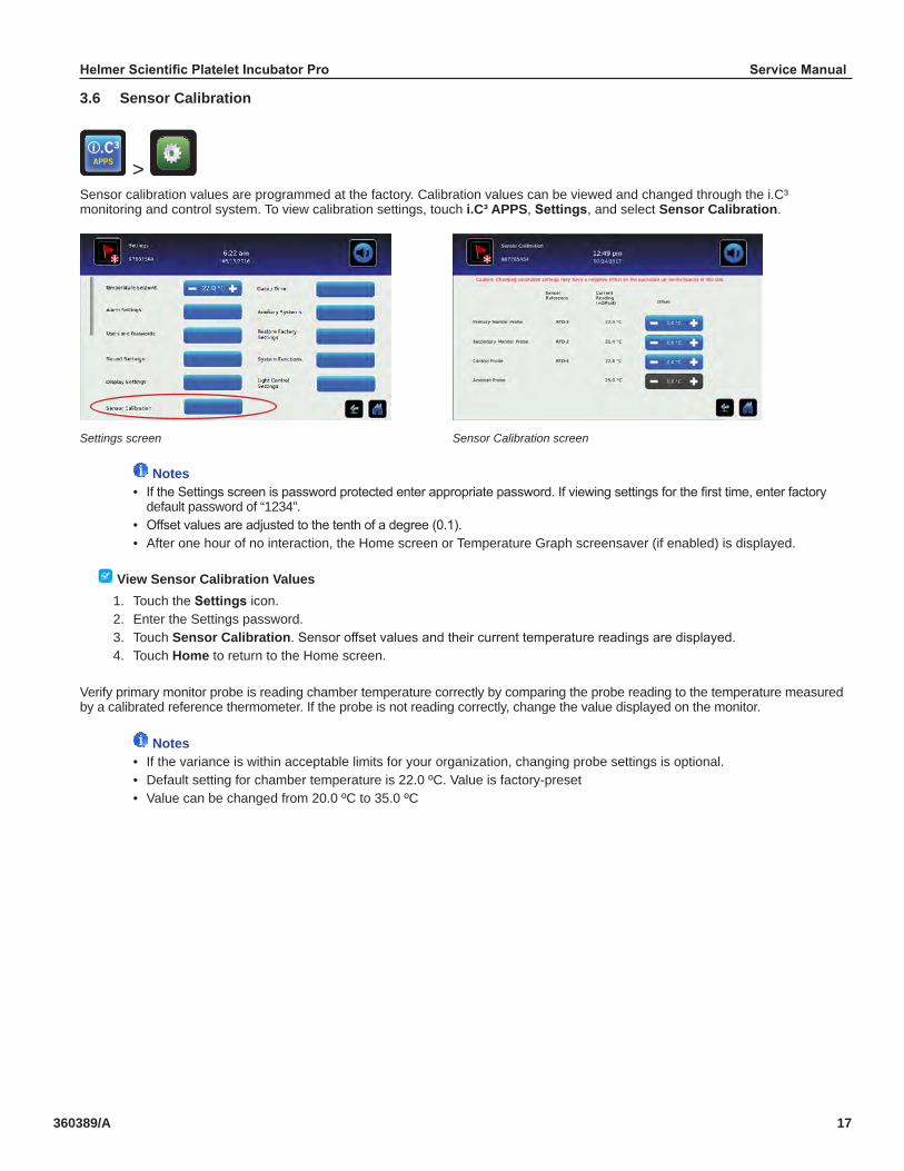
3.6 Sensor Calibration
> Sensor calibration values are programmed at the factory. Calibration values can be viewed and changed through the i.C³ monitoring and control system. To view calibration settings, touch i.C³ APPS, Settings, and select Sensor Calibration.
Settings screen Sensor Calibration screen
Notes• If the Settings screen is password protected enter appropriate password. If viewing settings for the first time, enter factory default password of “1234”.• Offset values are adjusted to the tenth of a degree (0.1).• After one hour of no interaction, the Home screen or Temperature Graph screensaver (if enabled) is displayed.
View Sensor Calibration Values1. Touch theSettingsicon.2. Enter the Settings password.3. Touch Sensor Calibration. Sensor offset values and their current temperature readings are displayed.4. Touch Home to return to the Home screen.
Verify primary monitor probe is reading chamber temperature correctly by comparing the probe reading to the temperature measured by a calibrated reference thermometer. If the probe is not reading correctly, change the value displayed on the monitor.
Notes• If the variance is within acceptable limits for your organization, changing probe settings is optional.• Default setting for chamber temperature is 22.0 ºC. Value is factory-preset• Value can be changed from 20.0 ºC to 35.0 ºC
Helmer Scientific Platelet Incubator Pro Service Manual
360389/A 18
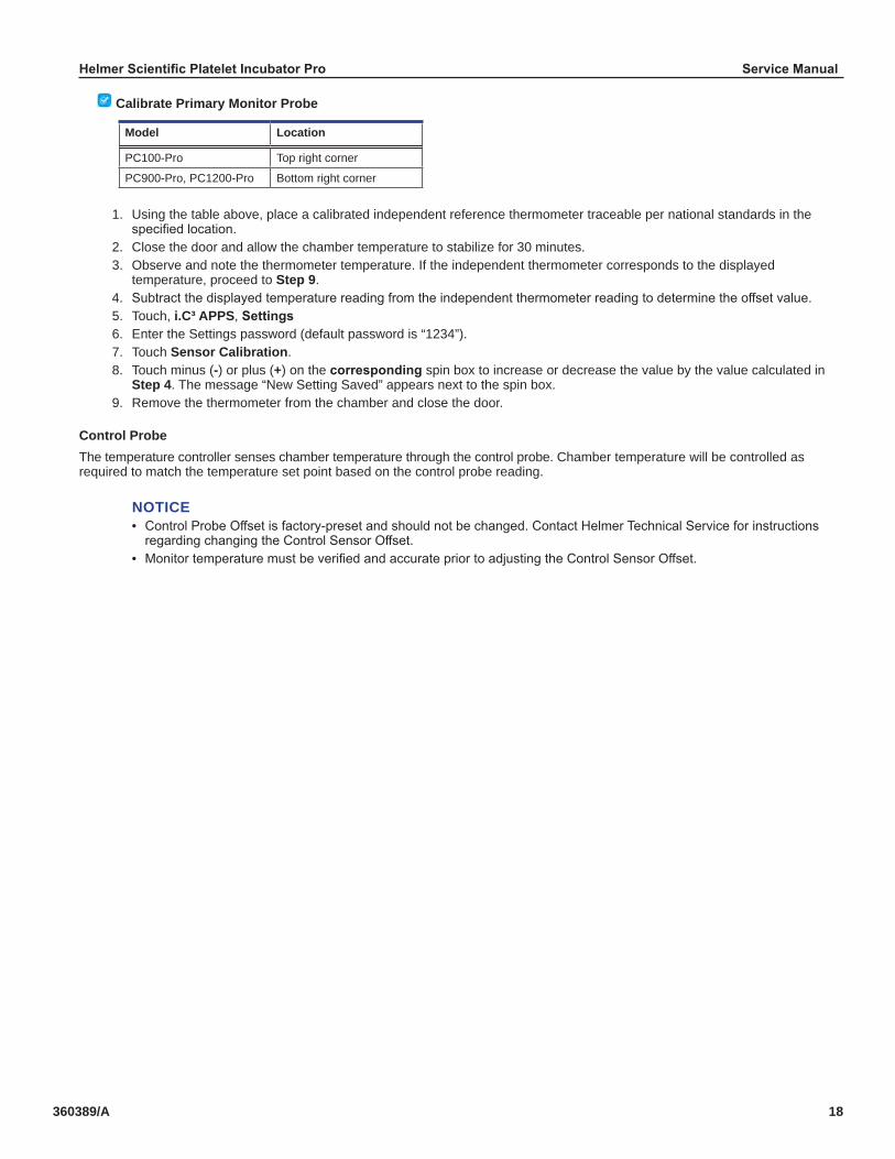
Calibrate Primary Monitor Probe
Model Location
PC100-Pro Top right corner
PC900-Pro, PC1200-Pro Bottom right corner
1. Using the table above, place a calibrated independent reference thermometer traceable per national standards in the specified location.2. Close the door and allow the chamber temperature to stabilize for 30 minutes.3. Observe and note the thermometer temperature. If the independent thermometer corresponds to the displayed temperature, proceed to Step 9.4. Subtract the displayed temperature reading from the independent thermometer reading to determine the offset value.5. Touch, i.C³ APPS, Settings6. Enter the Settings password (default password is “1234”).7. Touch Sensor Calibration.8. Touch minus (-) or plus (+) on the corresponding spin box to increase or decrease the value by the value calculated in Step 4. The message “New Setting Saved” appears next to the spin box.9. Remove the thermometer from the chamber and close the door.
Control ProbeThe temperature controller senses chamber temperature through the control probe. Chamber temperature will be controlled as required to match the temperature set point based on the control probe reading.
NOTICE• Control Probe Offset is factory-preset and should not be changed. Contact Helmer Technical Service for instructions regarding changing the Control Sensor Offset.• Monitor temperature must be verified and accurate prior to adjusting the Control Sensor Offset.
Helmer Scientific Platelet Incubator Pro Service Manual
360389/A 19
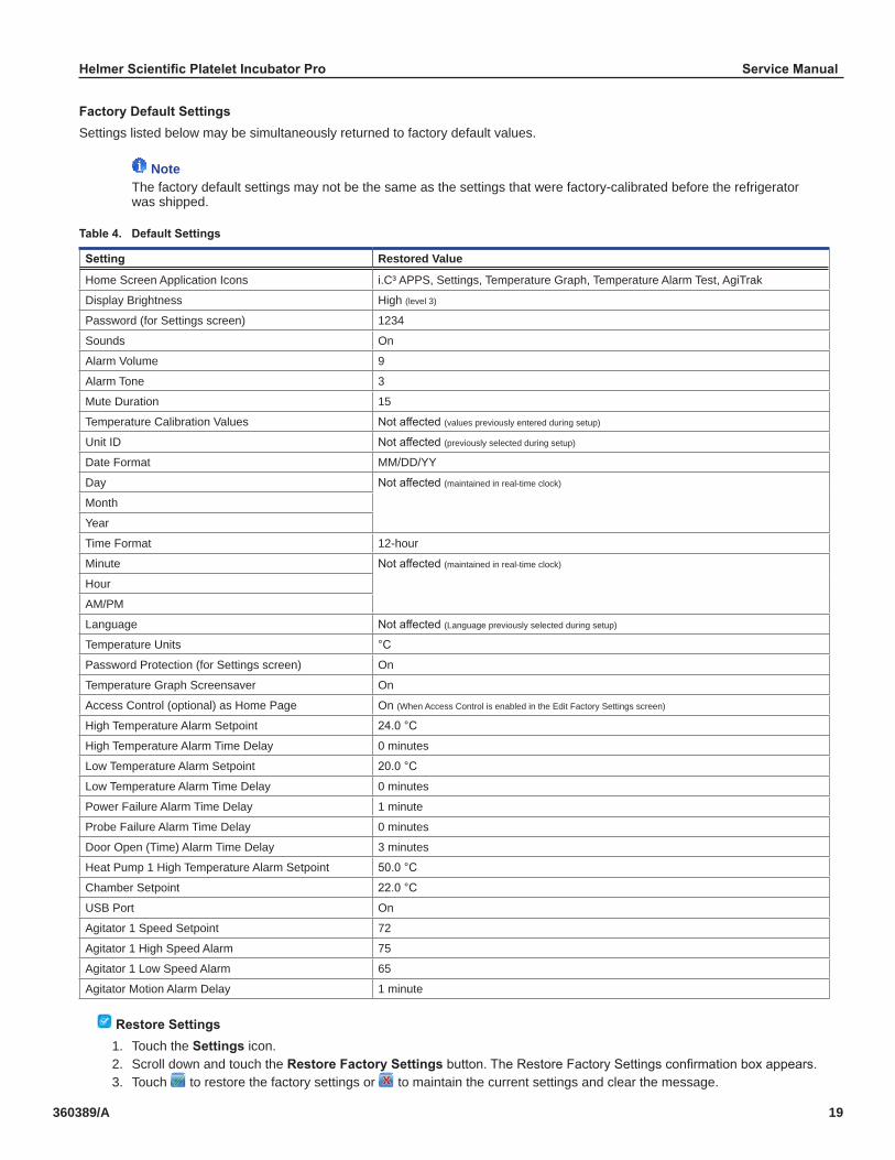
FactoryDefaultSettingsSettings listed below may be simultaneously returned to factory default values.
NoteThe factory default settings may not be the same as the settings that were factory-calibrated before the refrigerator was shipped.
Table4.DefaultSettings
Setting Restored Value
Home Screen Application Icons i.C³ APPS, Settings, Temperature Graph, Temperature Alarm Test, AgiTrak
Display Brightness High (level 3)
Password (for Settings screen) 1234
Sounds On
Alarm Volume 9
Alarm Tone 3
Mute Duration 15
Temperature Calibration Values Not affected (values previously entered during setup)
Unit ID Not affected (previously selected during setup)
Date Format MM/DD/YY
Day Not affected (maintained in real-time clock)
Month
Year
Time Format 12-hour
Minute Not affected (maintained in real-time clock)
Hour
AM/PM
Language Not affected (Language previously selected during setup)
Temperature Units °C
Password Protection (for Settings screen) On
Temperature Graph Screensaver On
Access Control (optional) as Home Page On (When Access Control is enabled in the Edit Factory Settings screen)
High Temperature Alarm Setpoint 24.0 °C
High Temperature Alarm Time Delay 0 minutes
Low Temperature Alarm Setpoint 20.0 °C
Low Temperature Alarm Time Delay 0 minutes
Power Failure Alarm Time Delay 1 minute
Probe Failure Alarm Time Delay 0 minutes
Door Open (Time) Alarm Time Delay 3 minutes
Heat Pump 1 High Temperature Alarm Setpoint 50.0 °C
Chamber Setpoint 22.0 °C
USB Port On
Agitator 1 Speed Setpoint 72
Agitator 1 High Speed Alarm 75
Agitator 1 Low Speed Alarm 65
Agitator Motion Alarm Delay 1 minute
RestoreSettings1. Touch the Settingsicon. 2. Scroll down and touch the RestoreFactorySettings button. The Restore Factory Settings confirmation box appears.3. Touch to restore the factory settings or to maintain the current settings and clear the message.

Helmer Scientific Platelet Incubator Pro Service Manual
360389/A 20
3.7 AgiTrak™System
> The AgiTrak™ system is integrated into the i.C3 monitoring system. The AgiTrak™ system simultaneously receives motion information from the Pro series platelet agitator. The Pro series platelet agitator installed in the Pro series platelet incubator is labeled as position 1 in the AgiTrak interface.The platelet incubator has a data port for the platelet agitator. The installed platelet agitator transmits motion and speed information to the AgiTrak™ system through a data cable and the data port in the platelet incubator. The AgiTrak™ system monitors platelet agitator motion on/off status, current agitation speed and cycle counts.If motion is not detected for the pre-configured amount of time, the AgiTrak™ system activates an alarm and records the alarm event(s) in the event log. For agitation information to be monitored correctly, the platelet agitator position must be enabled in the AgiTrak interface. Disable a platelet agitator position through the AgiTrak interface if the position is not is use.The Agitator Motion Alarm Delay specifies the longest length of time the agitator can be stopped prior to alarm. If the time elapsed is greater than or equal to this value, an alarm activates. The default setting is one minute. The Setting can be changed from 0 minutes to 99 minutes.
Notes• The AgiTrak™ system is intended to replace each Pro series platelet agitator alarm. • Ensure Agitator 1 is enabled on the Agitator Setup and Info screen.
ViewReal-TimeAgitatorStatusAgitation speed and cycle counts may be viewed in real-time when a platelet agitator is installed in a platelet incubator. The cycle counter information is useful for troubleshooting problems with the agitation motion sensor, or for scheduling additional preventive maintenance functions.
NoteCycle count readings update frequently
Agitator Setup and Info screen Agitator Status screen
ViewAgitatorStatus:1. From the home screen, touch i.C3APPS,AgiTrak. The AgiTrak Setup and Info screen will appear.2. Select the AgitatorStatus button. The Agitator Status screen appears.3. Touch Back arrow to return to the Agitator Setup and Info screen or touch HOME to exit.
ViewAgitatorSpeedHistoryGraph1. From the home screen, touch i.C3APPS,AgiTrak. The AgiTrak Setup and Info screen will appear.2. Select the AgitatorStatus button. The Agitator Status screen appears.3. Touch the button showing the current agitator speed. The Agitator Speed History screen appears.4. Touch Back arrow to return to the Agitator Status screen or touch HOME to exit.
ViewAgitatorCountLog1. From the home screen, touch i.C3APPS,AgiTrak. The AgiTrak Setup and Info screen appears.2. Select the Agitator Count Log button. The Agitator Count Log screen appears.3. Touch Back arrow to return to the AgiTrak Setup and Info screen or touch HOME to exit.
Helmer Scientific Platelet Incubator Pro Service Manual
360389/A 21
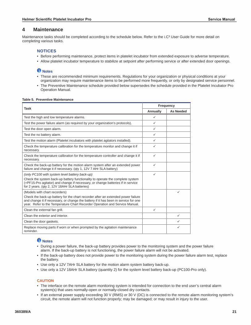
4 MaintenanceMaintenance tasks should be completed according to the schedule below. Refer to the i.C³ User Guide for more detail on completing various tasks.
NOTICES• Before performing maintenance, protect items in platelet incubator from extended exposure to adverse temperature.• Allow platelet incubator temperature to stabilize at setpoint after performing service or after extended door openings.
Notes• These are recommended minimum requirements. Regulations for your organization or physical conditions at your organization may require maintenance items to be performed more frequently, or only by designated service personnel.• The Preventive Maintenance schedule provided below supersedes the schedule provided in the Platelet Incubator Pro Operation Manual.
Table 5. Preventive Maintenance
TaskFrequency
Annually As Needed
Test the high and low temperature alarms. ü
Test the power failure alarm (as required by your organization’s protocols). ü
Test the door open alarm. ü
Test the no battery alarm. ü
Test the motion alarm (Platelet incubators with platelet agitators installed). ü
Check the temperature calibration for the temperature monitor and change it if necessary.
ü
Check the temperature calibration for the temperature controller and change it if necessary.
ü
Check the back-up battery for the motion alarm system after an extended power failure and change it if necessary. (qty 1, 12V 7 AHr SLA battery)
ü
(only PC100 with system level battery back-up)Check the system back-up battery functionality to operate the complete system (+PF15-Pro agitator) and change if necessary, or change batteries if in service for 2 years. (qty 2, 12V 18AHr SLA batteries)
ü
(Models with chart recorders)Check the back-up battery for the chart recorder after an extended power failure and change it if necessary, or change the battery if it has been in service for one year. Refer to the Temperature Chart Recorder Operation and Service Manual.
ü
Clean the external fan grill. ü
Clean the exterior and interior. ü
Clean the door gaskets. ü
Replace moving parts if worn or when prompted by the agitation maintenance reminder.
ü
Notes• During a power failure, the back-up battery provides power to the monitoring system and the power failure alarm. If the back-up battery is not functioning, the power failure alarm will not be activated.• If the back-up battery does not provide power to the monitoring system during the power failure alarm test, replace the battery.• Use only a 12V 7AHr SLA battery for the motion alarm system battery back-up.• Use only a 12V 18AHr SLA battery (quantity 2) for the system level battery back-up (PC100-Pro only).
CAUTION• The interface on the remote alarm monitoring system is intended for connection to the end user’s central alarm system(s) that uses normally-open or normally-closed dry contacts.• If an external power supply exceeding 30 V (RMS) or 30 V (DC) is connected to the remote alarm monitoring system’s circuit, the remote alarm will not function properly; may be damaged; or may result in injury to the user.
Helmer Scientific Platelet Incubator Pro Service Manual
360389/A 22
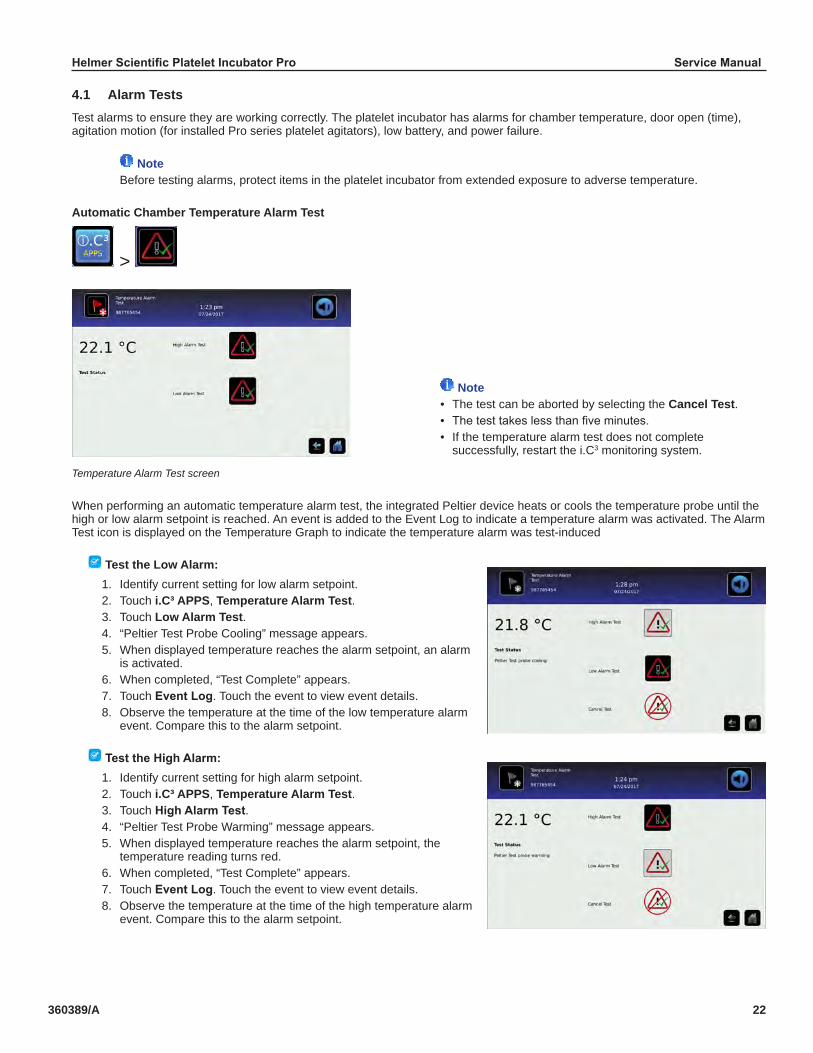
4.1 Alarm TestsTest alarms to ensure they are working correctly. The platelet incubator has alarms for chamber temperature, door open (time), agitation motion (for installed Pro series platelet agitators), low battery, and power failure.
NoteBefore testing alarms, protect items in the platelet incubator from extended exposure to adverse temperature.
Automatic Chamber Temperature Alarm Test
>
Temperature Alarm Test screen
When performing an automatic temperature alarm test, the integrated Peltier device heats or cools the temperature probe until the high or low alarm setpoint is reached. An event is added to the Event Log to indicate a temperature alarm was activated. The Alarm Test icon is displayed on the Temperature Graph to indicate the temperature alarm was test-induced
Test the Low Alarm:1. Identify current setting for low alarm setpoint.2. Touch i.C³ APPS, Temperature Alarm Test.3. Touch Low Alarm Test.4. “Peltier Test Probe Cooling” message appears.5. When displayed temperature reaches the alarm setpoint, an alarm is activated.6. When completed, “Test Complete” appears.7. Touch EventLog. Touch the event to view event details.8. Observe the temperature at the time of the low temperature alarm event. Compare this to the alarm setpoint.
TesttheHighAlarm:1. Identify current setting for high alarm setpoint.2. Touch i.C³ APPS, Temperature Alarm Test.3. Touch HighAlarmTest.4. “Peltier Test Probe Warming” message appears.5. When displayed temperature reaches the alarm setpoint, the temperature reading turns red.6. When completed, “Test Complete” appears.7. Touch EventLog. Touch the event to view event details.8. Observe the temperature at the time of the high temperature alarm event. Compare this to the alarm setpoint.
Note• The test can be aborted by selecting the Cancel Test.• The test takes less than five minutes.• If the temperature alarm test does not complete successfully, restart the i.C3 monitoring system.
i.Series Information

Helmer Scientific Platelet Incubator Pro Service Manual
360389/A 23
Cancel the test:1. Touch Cancel Test icon to end the alarm test. “Test Stopped” is displayed in the Test Status section of the display.
NoteWhen cancelling an automatic test, the message indicating the test is in progress clears immediately. If a setpoint was reached before the test was cancelled, the alarm activates and clears, as described previously.
Manual Chamber Temperature Alarm Test
Temperature Monitor Probe
Notes• Perform the low alarm test before the high alarm test to control the temperature more closely and complete the testing more quickly.• A test tube is recommended to facilitate the manual chamber alarm test on PC100-Pro platelet incubators.• Do not remove the chamber probe from PC100-Pro platelet incubators.• Temperature probes are fragile; handle with care.
Test the Low Alarm (PC100-Pro):1. Identify the current setting for the low alarm setpoint.2. Remove the installed platelet agitator, if necessary, to allow access to the to the monitor probe.3. Fill the test tube with enough cold water to immerse the probe at least 2” (51 mm).4. Slide the test tube upward to immerse the monitor probe tip and hold in place until the low temperature alarm is activated. (Alarm should sound when the temperature drops below the low alarm setpoint.)
TesttheHighAlarm(PC100-Pro):1. Identify the current setting for the high alarm setpoint.2. Fill the test tube with enough hot water to immerse the probe at least 2” (51 mm).3. Slide the test tube upward to immerse the monitor probe tip and hold in place until the high temperature alarm is activated. (Alarm should sound when the temperature rises above the high alarm setpoint.)4. If previously removed, reinstall the platelet agitator in the chamber.
PC100-Pro PC900-Pro/PC1200-Pro
Helmer Scientific Platelet Incubator Pro Service Manual
360389/A 24
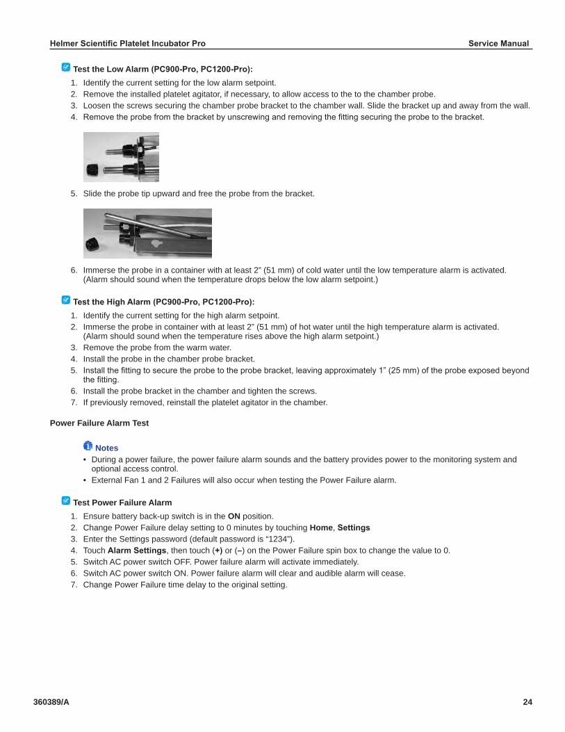
Test the Low Alarm (PC900-Pro,PC1200-Pro):1. Identify the current setting for the low alarm setpoint.2. Remove the installed platelet agitator, if necessary, to allow access to the to the chamber probe.3. Loosen the screws securing the chamber probe bracket to the chamber wall. Slide the bracket up and away from the wall.4. Remove the probe from the bracket by unscrewing and removing the fitting securing the probe to the bracket.
5. Slide the probe tip upward and free the probe from the bracket.
6. Immerse the probe in a container with at least 2” (51 mm) of cold water until the low temperature alarm is activated. (Alarm should sound when the temperature drops below the low alarm setpoint.)
TesttheHighAlarm(PC900-Pro,PC1200-Pro):1. Identify the current setting for the high alarm setpoint.2. Immerse the probe in container with at least 2” (51 mm) of hot water until the high temperature alarm is activated. (Alarm should sound when the temperature rises above the high alarm setpoint.)3. Remove the probe from the warm water.4. Install the probe in the chamber probe bracket.5. Install the fitting to secure the probe to the probe bracket, leaving approximately 1” (25 mm) of the probe exposed beyond the fitting.6. Install the probe bracket in the chamber and tighten the screws.7. If previously removed, reinstall the platelet agitator in the chamber.
Power Failure Alarm Test
Notes• During a power failure, the power failure alarm sounds and the battery provides power to the monitoring system and optional access control.• External Fan 1 and 2 Failures will also occur when testing the Power Failure alarm.
Test Power Failure Alarm1. Ensure battery back-up switch is in the ON position.2. Change Power Failure delay setting to 0 minutes by touching Home, Settings3. Enter the Settings password (default password is “1234”).4. Touch AlarmSettings, then touch (+) or (–) on the Power Failure spin box to change the value to 0.5. Switch AC power switch OFF. Power failure alarm will activate immediately.6. Switch AC power switch ON. Power failure alarm will clear and audible alarm will cease.7. Change Power Failure time delay to the original setting.

Helmer Scientific Platelet Incubator Pro Service Manual
360389/A 25
Door Open Alarm Test1. Change Door Open (Time) delay setting to 0 minutes by touching Home, Settings, 2. Enter the Settings password (default password is “1234”).3. TouchAlarmSettings, then touch (+) or (–) on the Door Open (Time) spin box to change the value to 0.4. Open door. Alarm will activate immediately.5. Close door. Alarm will clear, and audible alarm will cease.6. Change the Door Open (Time) setting to the original setting.
Motion Alarm Test1. Touch iC3 APPS, AgiTrak, then press the AgitatorSetup button.2. Enter the Settings password (default password is “1234”).3. Touch touch (+) or (–) on the Agitator 1 Motion Alarm Delay spin box to change the value to 0.4. Open door. The agitator will stop and the alarm will activate immediately.5. Close door. Alarm will clear, and audible alarm will cease.6. Change the Agitator 1 Motion Alarm Delay setting to the original setting.
4.2 Test and Replace Back-up BatteryOn all i.C³ screens, the Battery icon will appear in the header bar when the system is running on battery power, and the screen brightness will automatically be reduced. The monitoring system will automatically disable some features to extend battery life.
Notes• The monitoring system back-up battery provides power for up to 18 hours for monitoring and alarms.• An integrated full system back-up battery is available for the PC100-Pro.• When the PC100-Pro is running on full system back-up power, continued temperature control and agitation is provided for up to six hours.
Check the Back-up Battery1. Ensure battery switch is set to ON.2. Switch AC power switch OFF.3. The screen should continue to display information with reduced brightness and the battery icon will appear on the screen. If the display is blank, replace the battery. 4. When completed, switch AC power switch ON.
NOTICE• Use only batteries meeting manufacturer’s specifications.• Follow local guidelines for disposing of used batteries.
RemoveandReplaceMonitoringSystemBack-upBattery1. Switch the main power switch to OFF; switch the back-up battery switch to OFF; disconnect the power cord from the power receptacle.2. Using a #2 Phillips screwdriver, remove the screws securing the top panel. Set the screws and top panel aside. 3. Using a #2 Phillips screwdriver, remove the (2) two screws securing the battery bracket to the battery. Remove the bracket and set the bracket and screws aside.4. Disconnect the wires from the battery terminals.5. Remove the battery and discard.6. Install the new battery and attach the wires to the battery terminals.7. Reinstall the battery bracket and secure with 2 (two) screws using a #2 Phillips screwdriver.8. Reinstall the top cover and secure with screws using a #2 Phillips screwdriver.9. Reconnect the power cord to the wall receptacle. Switch the main power switch to ON; switch the back-up battery switch to ON. 10. Allow the temperature to stabilize at the setpoint before moving inventory back into the incubator.
Helmer Scientific Platelet Incubator Pro Service Manual
360389/A 26
Remove and Replace Full System Battery (optionalforPC100-Pro)1. Switch the main power switch to OFF; switch the back-up battery switch to OFF; disconnect the power cord from the power receptacle.2. Using a #2 Phillips screwdriver, remove the screws securing the top panel. Set the screws and top panel aside. 3. Using a #2 Phillips screwdriver, remove the (4) four screws securing the battery bracket to the batteries. Remove the bracket and set the bracket and screws aside.4. Use #2 Phillips screwdriver to remove the (4) four screws securing the wires to the battery terminals. 5. Remove the batteries and discard.6. Install new batteries and secure the wires to the battery terminals using a #2 Phillips screwdriver.7. Reinstall the battery bracket and secure with 4 (four) screws using a #2 Phillips screwdriver.8. Reinstall the top cover and secure with screws using a #2 Phillips screwdriver.9. Reconnect the power cord to the wall receptacle. Switch the main power switch to ON; switch the back-up battery switch to ON. 10. Allow the temperature to stabilize at the setpoint before moving inventory back into the incubator.

Helmer Scientific Platelet Incubator Pro Service Manual
360389/A 27
4.4 UpgradeSystemFirmwareHelmer may occasionally issue updates for the i.C³ firmware. Follow upgrade instructions included with the firmware update.
4.5 Clean the Platelet Incubator
WARNINGDisconnect platelet incubator from AC power prior to cleaning.
External Fan GrillClean the external fan grill using a soft brush and a vacuum cleaner.
ExteriorClean glass surfaces with soft cotton cloth and glass cleaner. Clean exterior surfaces with soft cotton cloth and non-abrasive liquid cleaner.
InteriorClean painted surfaces with mild detergent. Clean stainless steel surfaces with a general-purpose laboratory cleaner suitable for stainless steel. Clean glass surfaces with soft cotton cloth and glass cleaner.
Door GasketsClean with soft cloth and mild soap and water solution.
i.C³® TouchscreenClean touchscreen with a soft, dry cotton cloth.
Helmer Scientific Platelet Incubator Pro Service Manual
360389/A 28
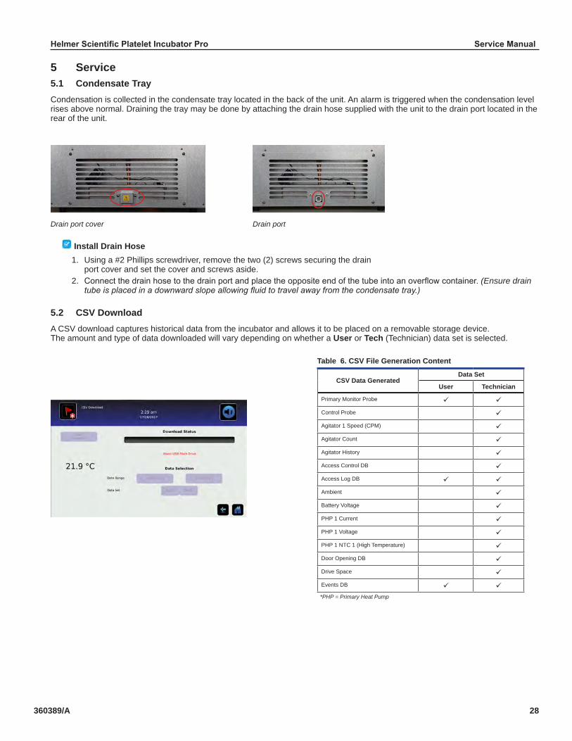
5 Service5.1 Condensate TrayCondensation is collected in the condensate tray located in the back of the unit. An alarm is triggered when the condensation level rises above normal. Draining the tray may be done by attaching the drain hose supplied with the unit to the drain port located in the rear of the unit.
Drain port cover Drain port
Install Drain Hose1. Using a #2 Phillips screwdriver, remove the two (2) screws securing the drain port cover and set the cover and screws aside.2. Connect the drain hose to the drain port and place the opposite end of the tube into an overflow container. (Ensure drain tube is placed in a downward slope allowing fluid to travel away from the condensate tray.)
5.2 CSV DownloadA CSV download captures historical data from the incubator and allows it to be placed on a removable storage device. The amount and type of data downloaded will vary depending on whether a User or Tech (Technician) data set is selected.
*PHP = Primary Heat Pump
Table 6. CSV File Generation Content
CSV Data GeneratedData Set
User Technician
Primary Monitor Probe ü ü
Control Probe ü
Agitator 1 Speed (CPM) ü
Agitator Count ü
Agitator History ü
Access Control DB ü
Access Log DB ü ü
Ambient ü
Battery Voltage ü
PHP 1 Current ü
PHP 1 Voltage ü
PHP 1 NTC 1 (High Temperature) ü
Door Opening DB ü
Drive Space ü
Events DB ü ü
Helmer Scientific Platelet Incubator Pro Service Manual
360389/A 29
Notes• The USB Port must be enabled prior to performing a CSV download.• Dates which are grayed out on the calendar do not contain recorded data and cannot be individually selected.
DownloadingCSVFile1. From the Home screen, select the Settings button. The Settings screen appears.2. Select the Auxiliary Systems button and turn on the USB Port. Select the Home icon to return to the Home screen.3. Select CSV Download. The CSV Download screen appears.4. Insert a USB flash drive in the USB drive located in the side of the i.C3 bezel.5. Touch the beginning DateRange button (left). A calendar will appear.6. Use the arrow buttons at the top or bottom of the calendar to select the beginning month, then select the date and press the green check mark to confirm.7. Touch the ending DateRange button (right). A calendar will appear.8. Use the arrow buttons at the top or bottom of the calendar to select the beginning month, then select the date and press the green check mark to confirm.9. Select User or Tech. data set.10. Touch Start Download. The Download Status bar will show the progression of the download. DO NOT remove flash drive while download is in progress.11. Once the download is complete, the Data download complete message will appear, and the flashdrive can be removed.

Helmer Scientific Platelet Incubator Pro Service Manual
360389/A 30
6 Troubleshooting
CAUTIONReview all safety instructions prior to troubleshooting.
6.1 General Operation Problems
Problem Possible Cause Action
Door does not open. Door lock is engaged Unlock door with key or enter user pin if equipped with Access Control
Hood does not open or close properly (PC900-Pro and PC1200-Pro).
Damping cylinder is faulty. Replace damping cylinder
Main power switch is on, but nothing is working.
Outlet connection is faulty. Verify power at the outlet. Repair original outlet or connect to a different outlet if necessary.
Power cord is faulty. • Check connections of power cord at outlet and incubator.• Check condition of the power cord. Replace if in poor condition.• Check that voltage through the cord is appropriate. If not, replace cord.
Power switch is faulty. Verify power output from the switch. Replace switch if necessary.
Primary Heat Pump (PHP) power supply or 24 VDC power supply is faulty.
Confirm PHP power supply and 24VDC is supplying power to other components. Replace supply if necessary.
Circuit breakers have been tripped. Reset circuit breakers
Chart Recorder is losing time. Chart Recorder hub is loose. Check tightness of center hub and tighten if necessary.
Chart Recorder is inoperative/locked up.
Chart Recorder is not receiving main power or battery power.
Confirm LED status light is solid green. If not, check main power to the Chart Recorder and the 9V battery is connected.
Chart Recorder is in (Chart Change) mode.
Confirm stylus is at correct temperature and the LED status light is solid green. If not, press the Chart Change button (C) to return the chart to normal operation.
Chart Recorder is locked up. Reset Chart Recorder by removing main power and 9V battery.
Chart Recorder is in wrong range or calibration.
Check chart range (LED will single flash in chart change mode) Adjust temperature calibration if needed. Reference Chart Recorder manual.
Agitation of installed platelet agitator has stopped.
Incubator door is open. Close incubator door.
Agitator power switch is turned OFF. Check agitator power switch and turn ON.
Agitator coiled DC power cord is loose or disconnected.
Check connections from interior incubator outlet to agitator.
Incubator moving on mounting surface.
Mounting surface is slick. • Ensure leveling feet are not worn. Change location or replace leveling feet if necessary.• Add incubator restraining brackets (included in packaging).
Internal agitator speed is set too high for incubator support surface.
Reduce agitator speed setting in AgiTrak.

Helmer Scientific Platelet Incubator Pro Service Manual
360389/A 31
6.2 Chamber Temperature Problems
Problem Possible Cause Action
Chamber temperature displayed is out of range.
Monitor is not calibrated. Confirm upper temperature probe is reading correctly. Calibrate probe if necessary.
Probe is out of place or faulty. Check probe location and connection. Replace probe if needed.
Primary Heat Pump (PHP) fans or coil are dirty.
Check Primary Heat Pump (PHP) fans and coil. Clean if necessary.
Temperature settings are incorrect. Check temperature settings and adjust accordingly.
Ambient air temperature around platelet incubator is too high.
Confirm platelet incubator is placed appropriately.
Internal chamber fan not running. Check fan connections. Replace if needed
PC100-Pro with full system battery back-up has been in back-up mode and exhausted the ability to operate the PHP thermal control system, but the agitator continues to run.
• Reconnect facility power.• If no facility power, switch agitator power switch OFF.
6.3 Alarm Activation Problems
Problem Possible Cause Action
Agitation motion alarm is active.
i.C3 monitoring system is not receiving motion information from the platelet agitator
On platelet incubator’s i.Center, verify agitation information is being received. Verify data cable is connected securely to platelet agitator and corresponding port in the platelet incubator. Tighten connections, replace if necessary.
Agitator position switch is set wrong.
Check agitator position switch, should be (1).
Agitator is not on. Ensure agitator power switch is on and power cables are connected.
Agitator Low Speed alarm is active.
Agitator is not agitating. Ensure agitator power connection is properly connected to the incubator.
Ensure proper clearance is provided for agitation. Remove any obstruction.
Shelf/drawers are overloaded or product is not placed evenly.
Reduce product load or place product load evenly.
Low alarm setting is too high. Ensure low speed alarm condition is set at least 2 CPM below setpoint.
Agitator motor or gearbox is not functioning properly.
Inspect agitator motor/gearbox. Replace if necessary.
Agitator High Speed alarm is active.
High alarm setting is too low. Ensure high speed alarm condition is set at least 2 CPM above setpoint.
Maintenance alarm is active. Wheels are worn or out of round. Inspect wheels. Replace if necessary.
Wheel maintenance timer has timed out.
Inspect wheels and clear maintenance alarm if wheels are okay.
Communication alarm is active.
Agitator power switch is OFF. Turn agitator power switch ON.
Coiled black power cable to the agitator is loose or disconnected.
Ensure power cable is properly connected to the installed agitator.
Communication cable to the agitator is loose or disconnected.
Ensure communication cable is properly connected to the installed agitator.
Helmer Scientific Platelet Incubator Pro Service Manual
360389/A 32
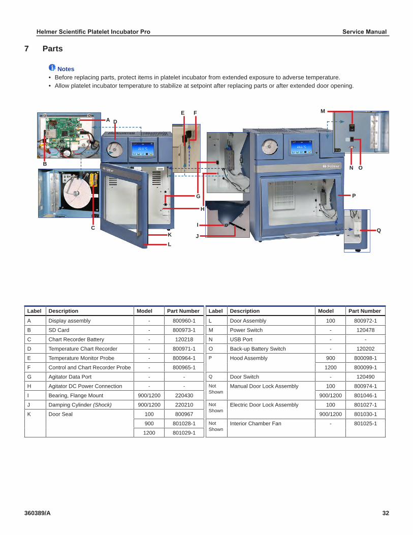
7 Parts
Notes• Before replacing parts, protect items in platelet incubator from extended exposure to adverse temperature.• Allow platelet incubator temperature to stabilize at setpoint after replacing parts or after extended door opening.
Label Description Model Part Number Label Description Model Part Number
A Display assembly - 800960-1 L Door Assembly 100 800972-1
B SD Card - 800973-1 M Power Switch - 120478
C Chart Recorder Battery - 120218 N USB Port - -
D Temperature Chart Recorder - 800971-1 O Back-up Battery Switch - 120202
E Temperature Monitor Probe - 800964-1 P Hood Assembly 900 800098-1
F Control and Chart Recorder Probe - 800965-1 1200 800099-1
G Agitator Data Port - - Q Door Switch - 120490
H Agitator DC Power Connection - - Not Shown
Manual Door Lock Assembly 100 800974-1
I Bearing, Flange Mount 900/1200 220430 900/1200 801046-1
J Damping Cylinder (Shock) 900/1200 220210 Not Shown
Electric Door Lock Assembly 100 801027-1
K Door Seal 100 800967 900/1200 801030-1
900 801028-1 Not Shown
Interior Chamber Fan - 801025-1
1200 801029-1
Q
ON
M
I
KC
H
G
FEDA
JL
B
P
Helmer Scientific Platelet Incubator Pro Service Manual
360389/A 33
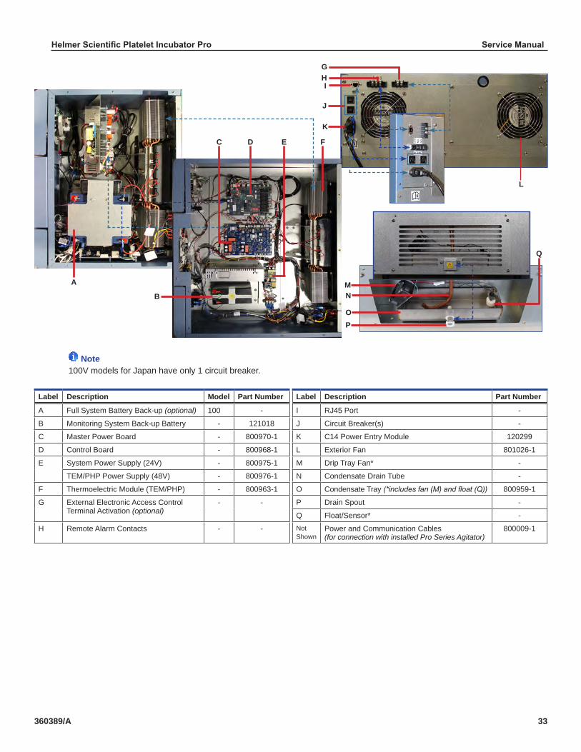
Note100V models for Japan have only 1 circuit breaker.
Label Description Model Part Number Label Description Part Number
A Full System Battery Back-up (optional) 100 - I RJ45 Port -
B Monitoring System Back-up Battery - 121018 J Circuit Breaker(s) -
C Master Power Board - 800970-1 K C14 Power Entry Module 120299
D Control Board - 800968-1 L Exterior Fan 801026-1
E System Power Supply (24V) - 800975-1 M Drip Tray Fan* -
TEM/PHP Power Supply (48V) - 800976-1 N Condensate Drain Tube -
F Thermoelectric Module (TEM/PHP) - 800963-1 O Condensate Tray (*includes fan (M) and float (Q)) 800959-1
G External Electronic Access Control Terminal Activation (optional)
- - P Drain Spout -
Q Float/Sensor* -
H Remote Alarm Contacts - - Not Shown
Power and Communication Cables (for connection with installed Pro Series Agitator)
800009-1
A
PO
NM
L
K
J
IH
FEDC
B
Q
G

Helmer Scientific Platelet Incubator Pro Service Manual
360389/A 34
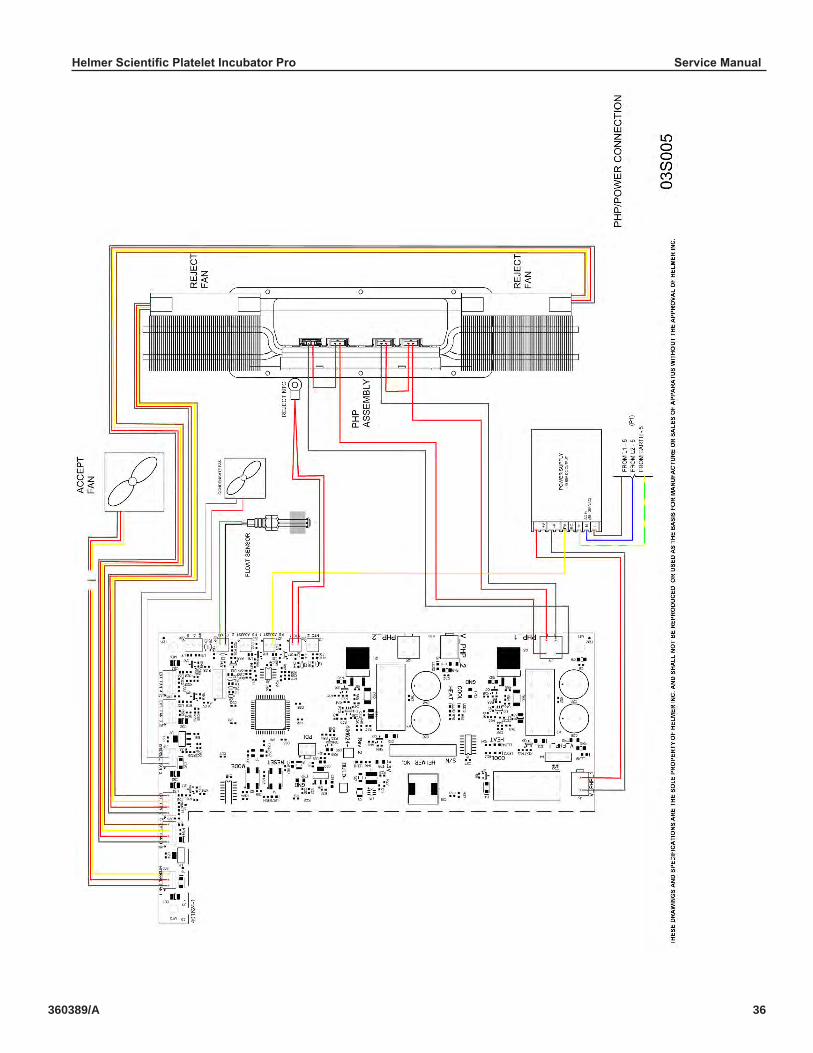
8 Schematics8.1 PC100-Pro, PC900-Pro, PC1200-Pro

Helmer Scientific Platelet Incubator Pro Service Manual
360389/A 35
Helmer Scientific Platelet Incubator Pro Service Manual
360389/A 36

Helmer Scientific Platelet Incubator Pro Service Manual
360389/A 37
Appendix A: WarrantyFor technical service needs, please contact Helmer at 800-743-5637 or www.helmerinc.com. Have the model and serial number available when calling.
Rapid ResolutionWhen a warranty issue arises it is our desire to respond quickly and appropriately. The service department at Helmer is there for you. Helmer will oversee the handling of your warranty service from start to finish. Therefore, Helmer must give advance authorization for all service calls and/or parts needs relating to a warranty issue. Any repeat service calls must also be authorized as well. This allows for proper diagnosis and action. Helmer will not be responsible for charges incurred for service calls made by third parties prior to authorization from Helmer. Helmer retains the right to replace any product in lieu of servicing it in the field.
Thermoelectric ModuleFor the warranty period listed below, Helmer will supply the thermoelectric module, if it is determined to be defective, at no charge, including freight. Helmer will not be liable for installation, or miscellaneous charges required to install the thermoelectric module beyond the first year of the warranty period. ♦ Pro series model thermoelectric module warranty period is five (5) years.
PartsFor a period of two (2) years, Helmer will supply at no charge, including freight, any part that fails due to defects in material or workmanship under normal use, with the exception of expendable items. Expendable items include glass, batteries, and door gaskets. Inspection of defective parts by Helmer will be final in determining warranty status. Warranty procedures must be followed in all events.
LaborFor a period of one (1) year, Helmer will cover repair labor costs, provided the product is returned to Helmer for warranty service. Alternatively, your facility’s staff may work with a Helmer technician to make repairs on site. Labor costs for repairs performed at a location other than Helmer, or for repairs made without the assistance of a Helmer technician, will be the responsibility of the end user.
Additional Warranty InformationThe time periods set forth above begin two weeks after the original date of shipment from Helmer. Warranty procedures set forth above must be followed in all events.THERE ARE NO WARRANTIES WHICH EXTEND BEYOND THE DESCRIPTION ON THE FACE HEREOF. THIS WARRANTY IS EXCLUSIVE AND IN LIEU OF ALL OTHER WARRANTIES, EXPRESS OR IMPLIED, INCLUDING WITHOUT LIMITATION ANY WARRANTY OF MERCHANTABILITY OR FITNESS FOR A PARTICULAR PURPOSE. NO WARRANTIES OF MERCHANTABILITY OR FITNESS FOR PARTICULAR PURPOSE SHALL APPLY.THE LIABILITY, IF ANY, OF HELMER FOR DIRECT DAMAGES WHETHER ARISING FROM A BREACH OF ANY SALES AGREEMENT, BREACH OF WARRANTY, NEGLIGENCE, OR INDEMNITY, STRICT LIABILITY OR OTHER TORT, OR OTHERWISE WITH RESPECT TO THE GOODS OR ANY SERVICES IS LIMITED TO AN AMOUNT NOT TO EXCEED THE PRICE OF THE PARTICULAR GOODS OR SERVICES GIVING RISE TO THE LIABILITY. IN NO EVENT SHALL HELMER BE LIABLE FOR ANY INDIRECT, INCIDENTAL, CONSEQUENTIAL, OR SPECIAL DAMAGES, INCLUDING WITHOUT LIMITATION DAMAGES RELATED TO LOST REVENUES OR PROFITS, OR LOSS OF PRODUCTS.This warranty does not cover damages caused in transit, during installation by accident, misuse, fire, flood, or acts of God. Further, this warranty will not be valid if Helmer determines the failure was caused by a lack of performing recommended equipment maintenance (per Helmer manual) or by using the product in a manner other than for its intended use. Installation and calibration are not covered under this warranty agreement.
Outside of USA and CanadaConsult your local distributor for warranty information.

Helmer Scientific14400 Bergen Boulevard, Noblesville, IN 46060 USA
Copyright © 2019 Helmer, Inc. 360389/A