Pipelining 101: An Overview of the Natural Gas Industry · Pipelining 101: An Overview of the...
51
PDHonline Course C312 (4 PDH) Pipelining 101: An Overview of the Natural Gas Industry 2012 Instructor: H. Wayne Harper, PE PDH Online | PDH Center 5272 Meadow Estates Drive Fairfax, VA 22030-6658 Phone & Fax: 703-988-0088 www.PDHonline.org www.PDHcenter.com An Approved Continuing Education Provider
Transcript of Pipelining 101: An Overview of the Natural Gas Industry · Pipelining 101: An Overview of the...

PDHonline Course C312 (4 PDH)
Pipelining 101: An Overviewof the Natural Gas Industry
2012
Instructor: H. Wayne Harper, PE
PDH Online | PDH Center5272 Meadow Estates Drive
Fairfax, VA 22030-6658Phone & Fax: 703-988-0088
www.PDHonline.orgwww.PDHcenter.com
An Approved Continuing Education Provider
PIPELINING 101:
AN OVERVIEW OF THE NATURAL GAS INDUSTRY & TRANSMISSION PIPELINES
AS LINEAR PROJECTS
H. WAYNE HARPER, P.E.
AUGUST 2008

www.PDHcenter.com PDH Course #C312 www.PDHonline.org
Pipelining 101: An Overview of the Natural Gas Industry & Transmission Pipelines as Linear Projects i
TABLE OF CONTENTS
DESCRIPTION PAGE
1.0 NATURAL GAS .........................................................................................................................1 2.0 OVERVIEW OF THE NATURAL GAS INDUSTRY IN AMERICA......................................................3 2.1 Gas Producing and Processing Companies....................................................................3
2.2 Gas Transmission Pipelines ...........................................................................................3 2.3 Natural Gas Storage .......................................................................................................4
2.3.1 Gas Storage Fields .............................................................................................4 2.3.2 Liquefied Natural Gas........................................................................................5 2.4 Gas Distribution.............................................................................................................5 3.0 DEVELOPMENT AND CONSTRUCTION OF TRANSMISSION PIPELINES.........................................6
3.1 Pre-Construction Activities............................................................................................6 3.1.1 Project Planning .................................................................................................6 3.1.2 Design ................................................................................................................6 3.1.3 Permitting...........................................................................................................7 3.1.4 Acquisition of Right-of-Way .............................................................................8
3.2 Standard Pipeline Construction Processes .....................................................................9 3.2.1 Clearing............................................................................................................10 3.2.2 Grading ............................................................................................................12 3.2.3 Trenching .........................................................................................................13 3.2.4 Pipe Stringing...................................................................................................14 3.2.5 Pipe Bending....................................................................................................15 3.2.6 Welding............................................................................................................15 3.2.7 Coating.............................................................................................................17 3.2.8 Lowering-in......................................................................................................18 3.2.9 Backfilling........................................................................................................18 3.2.10 Hydrostatic Testing..........................................................................................19 3.2.11 Final Grading and Restoration .........................................................................20
3.3 Special Construction Techniques.................................................................................20 3.3.1 Waterbody Crossings – Open Cut....................................................................21 3.3.2 Waterbody Crossings – Dry Cut ......................................................................21 3.3.3 Waterbody Crossings – Horizontal Directional Drilling .................................23 3.3.4 Wetland Crossings ...........................................................................................26 3.3.5 Road Bores.......................................................................................................28
www.PDHcenter.com PDH Course #C312 www.PDHonline.org
Pipelining 101: An Overview of the Natural Gas Industry & Transmission Pipelines as Linear Projects ii
FIGURE LISTING
DESCRIPTION PAGE
Figure 1: Properties of Natural Gas and Propane.......................................................................1
Figure 2: Gas & Oil Formation ..................................................................................................2
Figure 3: Natural Gas Industry Flowchart..................................................................................3
Figure 4: Gas Transmission Pipeline Network...........................................................................4
Figure 5: LNG Tanker Ship........................................................................................................5
Figure 6: Hydro-Ax Mower......................................................................................................10
Figure 7: Hydro-Ax Mower Cutting Deck Bottom ..................................................................10
Figure 8: Hydro-Ax with Active Elevated Cutting Deck.........................................................10
Figure 9: Hydro-Ax Tree Cutter (two views)...........................................................................11
Figure 10: Mechanical Feed Chipper (two views) .....................................................................11
Figure 11: Waterbody Bridge Installation..................................................................................12
Figure 12: Equipment Support “Rip-Rap” Log Corduroy Road Through Wetland...................12
Figure 13: “Typical Side-Hill” Grading Schematic ...................................................................13
Figure 14: “Two Tone” Grading Schematic...............................................................................13
Figure 15: Ditching Machine......................................................................................................14
Figure 16: Floatable “Swamp-Hoe” Ditching within Wetland ..................................................14
Figure 17: Backhoe with Hydraulically Operated Jackhammer for Rock Breaking..................14
Figure 18: “John Henry” Drilling Holes for the Insertion of Blast Explosives..........................14
Figure 19: Stringing Truck Delivering Pipe...............................................................................15
Figure 20: Pipe Strung Along the Ditchline ...............................................................................15
Figure 21: Pipe Bending Machine..............................................................................................15
Figure 22: “Over-bend” Pipe......................................................................................................15
Figure 23: Lining Up Two Pipe Joints for “Tie-In Weld” Using Clamps..................................16
Figure 24: Mainline Welder at Work .........................................................................................16
Figure 25: Application of Fusion Bond Epoxy - Cooling Heat Ring (left of center)
and Finished Field Coating (right of center).............................................................17
Figure 26: Application of Heat-Shrink Sleeve – Wrapping of Pipe with
Sleeve in a Overlapping Pattern................................................................................17
Figure 27: Sidebooms Lowering-In Pipeline .............................................................................18

www.PDHcenter.com PDH Course #C312 www.PDHonline.org
Pipelining 101: An Overview of the Natural Gas Industry & Transmission Pipelines as Linear Projects iii
FIGURE LISTING (CONTINUED)
DESCRIPTION PAGE
Figure 28: Sidebooms with Counter-Weights Fully Extended Holding a Heavy Load .............18
Figure 29: “Ozzie” Type Padding Machine Self Feeds from the Spoil Pile ..............................19
Figure 30: “Dyndopad” Type Padding Machine is Manually Fed by Backhoe .........................19
Figure 31: Successful Right-of-Way Restoration.......................................................................20
Figure 32: Open-Cut Waterbody Crossing – Backhoe Excavating River Bed ..........................21
Figure 33: Open-Cut Waterbody Crossing – Backhoe Transferring Material in Relay.............21
Figure 34: Simple Flumed Dry-Cut Waterbody Crossing with Upstream Coffer Dam.............23
Figure 35: Custom Flumed Dry-Cut Waterbody Crossing with Excavation Ready to Begin....23
Figure 36: Fabrication of Dual Flume Assembly .......................................................................23
Figure 37: Functioning Dual Flume Assembly – River Entering Flumes (upper right)
Excavated Pipeline Trench (lower right) ..................................................................23
Figure 38: HDD Pilot Hole Drilling...........................................................................................24
Figure 39: HDD Bore Hole Reaming.........................................................................................25
Figure 40: New Reamer Ready for Maiden Voyage ..................................................................25
Figure 41: Active HDD Rig .......................................................................................................25
Figure 42: HDD Pipe Pulling .....................................................................................................26
Figure 43: Conventional Wetland Construction Method ...........................................................27
Figure 44: Road Bore Operation ................................................................................................28

www.PDHcenter.com PDH Course #C312 www.PDHonline.org
Pipelining 101: An Overview of the Natural Gas Industry & Transmission Pipelines as Linear Projects iv
TABLE LISTING
DESCRIPTION PAGE
Table 1: Areas with the Highest Average Annual Natural Gas Consumption..........................1
Table 2: Typical Dry-Cut Crossing Design Layouts for various Flow Regimes....................22
ATTACHMENT LISTING
DESCRIPTION
A: Pipeline Industry Acronyms
B: Federal Energy Regulatory Commission Natural Gas Pipeline Permitting
Flowcharts

www.PDHcenter.com PDH Course #C312 www.PDHonline.org
Pipelining 101: An Overview of the Natural Gas Industry & Transmission Pipelines as Linear Projects Page 1 of 31
PIPELINING 101: AN OVERVIEW OF THE NATURAL GAS INDUSTRY & TRANSMISSION PIPELINES AS LINEAR PROJECTS 1.0 NATURAL GAS Natural gas – it heats our water, cooks our food, warms our homes, fuels our factories, powers some of our transportation, and even generates some of the electricity we use every day. Natural gas is the world’s cleanest burning fossil fuel and is composed primarily of methane, the lightest of hydrocarbon compounds (see Figure 1). Because of its high-energy value and its low emission of carbon dioxide (CO2) and nitrogen oxides (NOX) when burned, it has become the fuel of choice for new electric power plants and new industrial factories.
Figure 1: Properties of Natural
Gas and Propane
There are many different theories as to the origins of fossil fuels. The most widely accepted theory states that fossil fuels are formed when organic matter, such as the remains of a plant or animal, is compressed under the earth, at very high pressure for a very long time. For natural gas, this is referred to as thermogenic methane. Similar to the formation of oil, thermogenic methane is formed from organic particles that are covered in mud and other sediment. Over time, more and more sediment and mud and other debris are piled on top of the organic matter. This sediment and debris puts a great deal of pressure on the organic matter, which compresses it. This compression, combined with high temperatures found deep underneath the earth, break down the carbon bonds in the organic matter. The deeper under the earth's crust, the higher the temperature. At low temperatures (shallower deposits), more oil is produced relative to natural gas. At higher temperatures, however, more natural gas is created, as opposed to oil. That is why natural gas is usually associated with oil in deposits that are 1 to 2 miles below the earth's crust. Deeper deposits, very far underground, usually contain primarily natural gas, and in many cases, pure methane. A schematic of this formation process is depicted in Figure 2. Natural gas trapped underground is found in rock formations known as reservoirs. The reservoir rock is typically porous sand, sandstone, limestone, or dolomite. Oil and gas for the American market are produced from wells located across North America, both onshore and offshore. The Gulf of Mexico, the Gulf Coast, the Rock Mountains, and western Canada are the primary producing regions, but natural gas wells can be found just about anywhere in North America.

www.PDHcenter.com PDH Course #C312 www.PDHonline.org
Pipelining 101: An Overview of the Natural Gas Industry & Transmission Pipelines as Linear Projects Page 2 of 31
Natural gas is also produced, shipped and consumed globally. A listing of countries with the highest average annual natural gas consumption is provided in the table below:
Table 1: Areas with the Highest Average Annual Natural Gas Consumption
Ranking Country / Region Average Annual Natural Gas Consumption (1,000 m3)
Percentage of Total
Date of Information
--- World 3,025,000,000 100% 2005 est.
1 Russia 610,000,000 20.2% 2007 est.
2 United States 604,000,000 20.0% 2005 est.
3 European Union 496,700,000 16.4% 2005 est.
4 Iran 98,190,000 3.2% 2005 est. 5 Germany 96,840,000 3.2% 2005 est. 6 Canada 92,760,000 3.1% 2005 est. 7 United Kingdom 91,160,000 3.0% 2005 est.
8 Japan 83,670,000 2.8% 2005 est.
9 Italy 82,640,000 2.7% 2005 est.
10 Ukraine 73,940,000 2.4% 2006 est.
(Source: The World Factbook via http://en.wikipedia.org)
Figure 2: Gas and Oil Formation

www.PDHcenter.com PDH Course #C312 www.PDHonline.org
Pipelining 101: An Overview of the Natural Gas Industry & Transmission Pipelines as Linear Projects Page 3 of 31
2.0 OVERVIEW OF THE NATURAL GAS INDUSTRY IN AMERICA The American natural gas industry delivers safe clean energy to homes and businesses through a primarily unseen underground network. Figure 3 and the following listing document these major components:
Figure 3: Natural Gas Industry Flowchart
• Over 5,000 gas well / extraction companies
• Over 2,100 gas gathering companies utilizing ~ 24,000 miles of pipeline
• Over 230 gas transmission companies utilizing ~ 304,000 miles of pipeline
• Over 1,400 local gas distribution companies utilizing ~ 1,900,000 miles of pipeline
(Source: U.S. Department of Transportation, Pipeline & Hazardous Materials
Safety Administration) A listing of acronyms common to the natural gas industry is provided in Attachment A. 2.1 GAS PRODUCING AND PROCESSING COMPANIES Gas producing companies extract gas out of underground wells located onland and offshore. From the wellhead, natural gas first travels through 2 to 30-inch diameter gathering system pipelines to processing plants. Here water and other impurities are stripped from the gas, leaving a clean burning fuel. 2.2 GAS TRANSMISSION PIPELINES The backbone of the natural gas industry is the gas transmission pipeline network. Gas transmission companies move the gas from processing plants to other parts of the state through intrastate pipelines and to other parts of the country through interstate pipelines (see Figure 4). These transmission pipelines range in size from 4-inch to 48-inch in diameter and operate at pressures from between 700 and 1,400 pounds per square inch (psi). The line pipe is constructed of high quality steel, typically between ¼ and ¾-inches thick, and is tested at numerous steps to ensure its ability to contain these high pressures safely. At compressor stations located about 50 to 100-miles apart along the pipeline, giant engines or turbines operate compressors to increase the pipeline pressure and keep the gas moving. Also spaced every 5 to 25-miles apart along the

www.PDHcenter.com PDH Course #C312 www.PDHonline.org
Pipelining 101: An Overview of the Natural Gas Industry & Transmission Pipelines as Linear Projects Page 4 of 31
pipeline are block or mainline valves. Transmission companies close these valves during testing, maintenance, or in an emergency to shut down the flow of gas in a section of the pipe.
The gas transmission pipeline network is considered a system of transportation along with airplanes, highways, railways, and shipping. As such, the Federal Department of Transportation (DOT) regulates the functions of gas transmission companies. The DOT requires all transmission companies to have procedures in place for preventing accidents, handling accidents if they occur, and educating the public about potentially hazardous conditions. 2.3 NATURAL GAS STORAGE The natural gas transmission business is generally a seasonal business, meaning that the volume of gas moved in a pipeline system changes with the seasons. To maximize the use of the pipeline capacity all year, and create additional flexibility in a pipeline system, pipeline companies operate gas storage facilities accessible to the pipeline transmission system. 2.3.1 Gas Storage Fields Natural gas is usually stored underground, in large storage reservoirs. There are three main types of underground storage: depleted gas reservoirs, aquifers, and salt caverns. These types of gas
Figure 4: Gas Transmission Pipeline Network

www.PDHcenter.com PDH Course #C312 www.PDHonline.org
Pipelining 101: An Overview of the Natural Gas Industry & Transmission Pipelines as Linear Projects Page 5 of 31
storage fields are extremely safe. When utilized, the pipeline company injects natural gas in to the storage field when demand is lower, such as the summer, and withdraws it from the storage field back into the pipeline during time of high demand, such as winter. 2.3.2 Liquefied Natural Gas Another way to store natural gas is to convert the gas to a liquid and store the liquid in aboveground tanks. While we think of natural gas as a “gas”, if we cool the gas to –260.25oF then the gas will become a liquid. During this phase transition, the gas reduces in volume 610 times. This compact super-cooled product is commonly known as liquefied natural gas (LNG) and is stored within insulated spherical containers on ships, as depicted in Figure 5, or in onland terminals. When a pipeline needs gas, the LNG is warmed in a process called regasification, causing it to quickly vaporize, expand in volume, and flow into the pipeline for transport. While LNG is reasonably costly to produce, advantages in technology are reducing the costs associated with the liquification and regasification of LNG. Because it is easy to transport, LNG can serve to make economical those stranded natural gas deposits for which the construction of pipelines is uneconomical. 2.4 GAS DISTRIBUTION Transmission pipelines deliver their gas to a variety of customers. While these can include direct connections to large industrial or power generating facilities, the most common destination is the city gate or entry point of the local distribution company (LDC). At this facility, the LDC receives gas for homes and businesses, reduces the pipeline pressure to between 30 and 90 psi. and adds the chemical mercaptan that gives the gas its distinctive odor. Since natural gas is odorless, this strong smelling additive provides a safety feature for quickly detecting minor leaks by LDC staff and the public. Gas distribution pipelines range in size from ¾ to 16-inches in diameter and are constructed from high quality steel or more increasing specialized plastic. There are more miles of buried distribution pipelines running down city streets and through neighborhoods in America than gas gathering and transmission pipelines combined.
Figure 5: LNG Tanker Ship

www.PDHcenter.com PDH Course #C312 www.PDHonline.org
Pipelining 101: An Overview of the Natural Gas Industry & Transmission Pipelines as Linear Projects Page 6 of 31
3.0 DEVELOPMENT OF NATURAL GAS TRANSMISSION PIPELINES The complete development of a new natural gas transmission pipeline can be divided into three primary phases; design, permitting, and construction. These phases are discussed in detail within the following sections. 3.1 PRE-CONSTRUCTION ACTIVITIES 3.1.1 Project Planning Project planning begins with the basics of supply and demand. If there is a need for natural gas, pipeline companies conduct a market analysis to estimate the size of the market. This gas supply requirement is typically expressed in terms of million cubic feet of gas per day. With this information engineers can begin to estimate the facilities needed to transport the required volumes of gas, including but not limited to, the basic design parameters of pipeline diameter, pressure, and wall thickness and the cost to construct the pipeline facilities. 3.1.2 Design The size of interstate pipelines varies, but in most cases a mainline, the major principal or main pipeline is designed to be in the range of 16 to 48 inches in diameter. Laterals, which are smaller diameter pipelines that either deliver gas to the mainline or take gas from the mainline, typically are 6 to 16 inches in diameter. The exact diameter of a pipeline is determined by the gas volume to be delivered and the pressure at which the pipeline company will be operated. In order to meet customer delivery requirements most interstate gas pipelines operate at a pressure of at least 600 pounds per square inch (psi), and typically about 1,000 psi. The wall thickness of the pipeline is determined by the maximum operating pressure (MAOP), and is based on published industry standards and federal regulations. The pipeline incorporates a design safety factor, prescibed by DOT's federal regulations, that is related to the type of construction and population density along the pipeline route. Engineers initially identify preliminary pipeline routes that will minimize impact to the public, public landowners and the environment. The pipeline company, typically will go through a process of reviewing available maps of the region to be traversed, and available published environmental data to determine a number of possible alternatives, depending on the characteristics of the region. This desktop work will then be augmented by use of aerial and ground reconnaissance, to identify and select a preferred route. Once a preferred route is identified, the pipeline company will begin contacting landowners to discuss the project and seek permission to conduct civil and environmental surveys. These

www.PDHcenter.com PDH Course #C312 www.PDHonline.org
Pipelining 101: An Overview of the Natural Gas Industry & Transmission Pipelines as Linear Projects Page 7 of 31
surveys are required for use in the detailed pipeline design and for preparing local, state and federal permit applications. Even though pipeline officials may begin discussions with landowners at this point, it is important to remember that the project is undergoing a feasibility analysis, and neither the project nor the pipeline route is finalized at this time. Selecting a pipeline route often involves discussing and evaluating options with landowners, environmental agencies and regulatory officials. If the market analysis ultimately justifies the cost of pipeline construction, only then will the pipeline company begin seeking permits and preparing a detailed project application for the Federal Energy Regulatory Commission. 3.1.3 Permitting Prior to construction, a pipeline company must obtain numerous local, state and federal permits and clearances. This is an intense and complicated process which can take years to complete for large projects. A project’s permitting team is a diverse group of professionals working together and typically contains engineers, biologists, archaeologists, lawyers, and lobbyist. The primary goal of the permitting process is to balance industry’s and the general public’s need for natural gas with the impacts that will occur during the pipeline’s development. Unlike the early years of pipeline construction, great measures are now taken to minimize the adverse impacts to natural resources along the route; including but not limited to, land, air, water, vegetation, wildlife and landowner properties. While the requirements vary with the extent of a specific project and potential environmental impacts, some of the typical permits and agency clearances are: Local • Building permits • Road crossing permits State • Land (Erosion and Sedimentation Permit) • Water (Hydrostatic Testwater Acquisition and Discharge Permit, Stormwater Discharge Permit) • Stream and River Crossings (State Environmental Agency) • Cultural Resources Preservation (State Historic Preservation Office) • Threatened and Endangered Species Preservation (State Fish & Wildlife Agency) • Air Emissions (State Environmental Agency) • Noise (State Environmental Agency) Federal • Wetlands Preservation and Crossings (U.S. Army Corps of Engineers) • Navigable Streams and Rivers (U.S. Army Corps of Engineers) • Threatened and Endangered Species (U.S. Fish & Wildlife Agency) • Air Emissions (U.S. Environmental Protection Agency) • Environmental Resource Reports (Federal Energy Regulatory Commission)
www.PDHcenter.com PDH Course #C312 www.PDHonline.org
Pipelining 101: An Overview of the Natural Gas Industry & Transmission Pipelines as Linear Projects Page 8 of 31
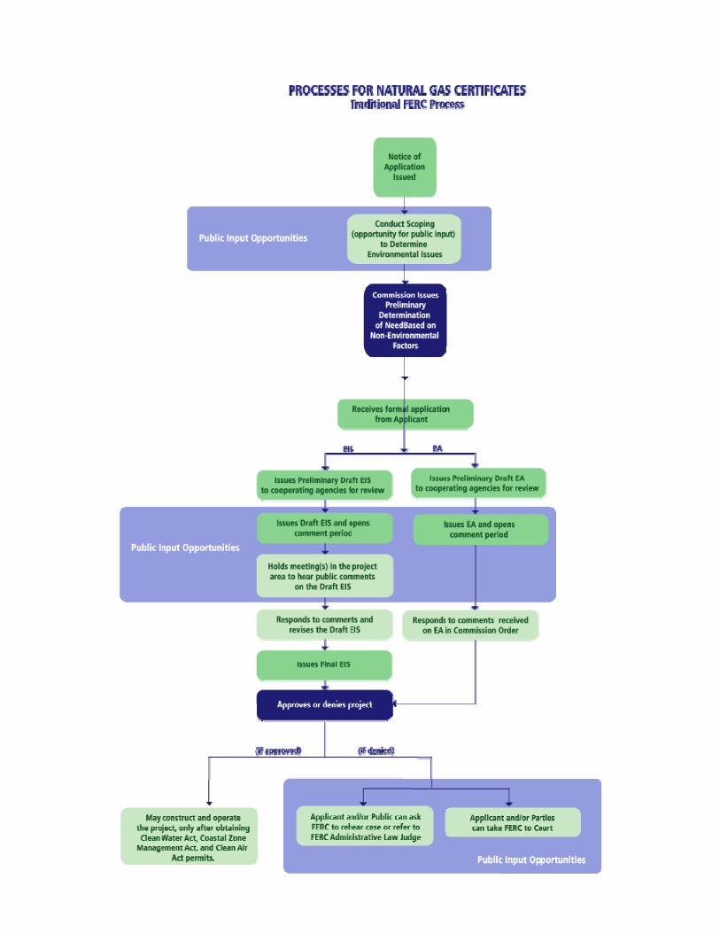
The Federal Energy Regulatory Commission (FERC) is charged by Congress with evaluating whether interstate natural gas pipeline projects proposed by private companies should be approved. This review includes the location, construction methods, modification, land acquisition, operation, and abandonment of interstate pipelines, facilities, and storage fields involved in moving natural gas across sate boundaries. The FERC functions as the central clearing house for all federal concerns and generally incorporates the stipulations of other federal agencies into its approval process. At times the FERC may also referee disputes and conflicting requirements between local, state, and/or federal agencies. Under Section 7(c) of the NGA, the FERC may issue a case-specific certificate authorizing a particular gas project. These Certificates include general conditions common to all projects and typically numerous project-specific constraints that were developed during the permitting process. Conversely, the FERC may issue a blanket certificate which allows a natural gas company to undertake a restricted number of routine activities, provided they comply with constraints on costs and environmental impacts. A series of flowcharts documenting the activities and decisions necessary within the FERC permitting process is provided in Attachment B. 3.1.4 Acquisition of Rights of Way The acquisition of a pipeline right-of-way often raises many questions with landowners -"Why is this the route for the pipeline? Why is the pipeline needed? What is the procedure for acquiring approval for use of my land? How will I be compensated? How will the land be restored after construction? Can I use the land after the pipeline is installed?" To answer those questions, let us look first at the process. The cornerstone of the right-of-way acquisition process is the negotiation of an Easement Agreement. This agreement covers key issues such as compensation, restoration of the land and restrictions on future use of the land. Once the pipeline route is selected, a right-of-way agent from the pipeline company will contact each affected landowner along the route to discuss the project and negotiate an easement agreement. In addition to a permanent easement the company requires to operate and maintain its pipeline after it is constructed, the company also requires a temporary easement during construction. The permanent easement typically is about 50 feet wide and the temporary easement typically will range between an additional 50 to 75 feet depending on the size of pipeline, larger pipelines require the use of bigger equipment and more room to operate. The amount of workspace required is also dependent on the type of terrain being crossed and any special construction requirements.

www.PDHcenter.com PDH Course #C312 www.PDHonline.org
Pipelining 101: An Overview of the Natural Gas Industry & Transmission Pipelines as Linear Projects Page 9 of 31
The landowner is normally compensated a fair market value for the permanent easement, which while typically allows the landowner continued use and enjoyment of their property, but with some limitations. The limitations typically prohibit structures and trees within the easement in order to preserve safe access of maintenance equipment when necessary and allows for uninhibited aerial inspection of the pipeline system. The landowner is generally compensated a lower value for the use of the temporary construction easement, since this land reverts back to the landowner after construction for their full use and enjoyment without any restrictions. Additionally, landowners are compensated for any damages/losses they may incur as a result of the construction across their property, such as loss of crop revenues. Sometimes, the landowner and the pipeline company may not be able to reach agreement on the terms of an easement. If the FERC Commission determines there is a public need for the pipeline, it will grant the pipeline company access to the land under eminent domain - the right of the government to take private land for public use, the same right afforded utilities, telecommunications companies, railroads and the transportation infrastructure in the U.S. It is important to point out that, for pipeline projects, eminent domain applies only to the specific facilities and uses authorized by the FERC Commission. State or federal courts then supervise the fair compensation and treatment of the landowner. 3.2 STANDARD PIPELINE CONSTRUCTION PROCESSES The construction of a natural gas transmission pipeline is a type of industrial manufacturing process. In a typical assembly line factory scenario, the workers are somewhat stationary and the product moves by them for increasing development. Whereas on a pipeline construction project, the product or pipeline is built in-place with the work crews moving along its length in organized succession performing differing tasks. As one crew completes its work, the next crew moves into position to complete its piece of the construction process. A large construction project is usually broken into manageable segments, known as spreads. A construction spread is typically between 30 to 100 miles in length and comprises a self-contained work zone with the necessary crews to complete the construction process. The major steps of this process are listed below and detailed in the following sections:
1. Clearing 2. Grading 3. Trenching 4. Pipe Stringing 5. Pipe Bending 6. Welding 7. Coating 8. Lowering-In 9. Backfilling 10. Hydrostatic Testing 11. Final Grading and Restoration

www.PDHcenter.com PDH Course #C312 www.PDHonline.org
Pipelining 101: An Overview of the Natural Gas Industry & Transmission Pipelines as Linear Projects Page 10 of 31
3.2.1 Clearing Clearing the right-of-way of vegetation is the first activity in the pipeline construction process. This begins with survey crews, who carefully mark all work areas to ensure that only the pre-approved construction workspace is cleared. Clearing itself utilizes various hand and heavy equipment techniques depending on land contours, vegetation type and cover, and the ability of the ground to support clearing equipment. These methodologies can vary drastically between regions of the country, as well as, along the length of a pipeline project itself. Relatively easy conditions can facilitate heavy equipment progressing quickly, while mountainous and swampy areas can require cutting with hand held equipment (chain saws) resulting in significantly slower vegetation processing. Provided below is a synopsis of the typical heavy equipment employed during clearing operations on transmission pipeline construction projects. Hydro-Ax Mowers Hydro-ax mowers are a unique hybrid of the following three heavy equipment components:
• Hydraulically operated industrial styled mower with pivoting “axe head” cutters • Front-end loader styled lifting ability for the mowing deck • Log skidder styled articulating body for increased mobility
This combination of features allows the hydro-ax mower to shred brush and smaller trees with ease. Various views of Hydro-ax mowers are depicted in Figures 6, 7, & 8.
Hydro-Ax Tree Cutters Hydro-ax tree cutters are similar to hydro-ax mowers with the cutting deck replaced by a hydraulically operated tree holder and sawhead (see Figure 9). This equipment type can drive
Figure 6: Hydro-Ax Mower
Figure 7: Hydro-Ax Mower Cutting Deck Bottom
Figure 8: Hydro-Ax with Active Elevated Cutting Deck

www.PDHcenter.com PDH Course #C312 www.PDHonline.org
Pipelining 101: An Overview of the Natural Gas Industry & Transmission Pipelines as Linear Projects Page 11 of 31
up to a tree, clamp onto it, and cut through a 20-inch diameter tree trunk in seconds. Once severed, the tree can be carried away and/or piled for further processing by other equipment.
Figure 9: Hydro-Ax Tree Cutter (two views)
Chippers Mechanical feed chippers are utilized on an increasing basis to process small trees, branches and slash (see Figure 10). This is particularly true in regions with burning restrictions. Depending on applicable permit conditions, the chips can be spread out for later mixing with the soil or transported off site. In some areas, the chips may even have some commercial value.
Figure 10: Mechanical Feed Chipper (two views)
While the chips produced from deciduous hardwood trees may be beneficial to some degree as a soil additive, it has been observed that the chips produced from evergreen trees may actually damage soil fertility. Specifically, evergreen chips have an acidic nature that easily and quickly

www.PDHcenter.com PDH Course #C312 www.PDHonline.org
Pipelining 101: An Overview of the Natural Gas Industry & Transmission Pipelines as Linear Projects Page 12 of 31
leaches into underlying soils. These damaged soil areas become very apparent during the post-construction restoration process. Once cut, the residual vegetation is ultimately processed and sorted according to its value. Marketable timber is typically cut to specified lengths and handled in accordance with landowner agreements. Unusable timber, branches, and slash may be disposed of in a number of ways, depending on local restrictions, terms of applicable permits, and/or landowner agreements. Usual disposal methods for unusable timber include burning, chipping, stockpiling, and burying. 3.2.2 Grading The grading crew is initiated after clearing and is typically responsible for completing most if not all of the following major tasks along the construction right-of-way:
• Installing erosion control devices; • Installing final waterbody crossing bridges (see Figure 11); • Removing tree stumps, boulders, rock outcroppings, and debris; • Blasting rock features as necessary; • Preparing a level-working surface for the heavy construction equipment that follows; • Stripping the topsoil in agricultural areas to a predetermined depth and stockpiling it in
designated storage areas as stipulated by permit conditions and landowner agreements; &, • Installing equipment support devices, such as timber mats, “rip-rap” logs (see Figure 12),
and/or fill dirt over geotextile fabric in areas of saturated soils, like wetlands.
Figure 11: Waterbody Bridge Installation
Figure 12: Equipment Support “Rip-Rap” Log Corduroy Road Through Wetland
Transmission pipelines commonly traverse along side hills. To create a level-working surface in these areas, soil material is relocated during construction from the higher side to the lower side of the right-of-way using backhoes and bulldozers (see Figure 13). In areas where the side slope angle is severe, the cut and fill technique is modified to produce two level working surfaces.

www.PDHcenter.com PDH Course #C312 www.PDHonline.org
Pipelining 101: An Overview of the Natural Gas Industry & Transmission Pipelines as Linear Projects Page 13 of 31
This is referred to as “two tone” grading (see Figure 14). One level will be utilized for the pipeline trench and spoil storage, while the other level will contain the pipe during preparation and the travel lane for trucks and equipment. Once construction activities are completed, original contours are reestablished during the restoration process.
Figure 13
Figure 14
3.2.3 Trenching Following grading, the centerline of the trench is surveyed and staked. The trench will be excavated along this line to a depth sufficient to provide at least the minimum cover as required by U.S. Department of Transportation (“DOT”) specifications. Total trench depths vary depending on pipe diameter and location along the pipeline. The DOT requires the top of pipe to be buried a minimum of 30-inches in rural areas, 36-inches in non-rural areas, and even deeper under waterbody, road, and railroad crossings. The method of excavation depends upon the soil conditions encountered. Optimal soils with little rock are ideal for rotary wheel type ditching machines (see Figure 15), while backhoes are the all purpose choice for most situations. Extremely saturated soils require “floating” backhoes (see Figure 16), and/or cranes with clamshells or draglines. Typically, material excavated from the trench will be piled parallel and adjacent to the trench on the narrow side of the construction work area. In wetland resource areas, topsoil will be segregated from the subsoil during trench excavation and ultimately replaced in the correct order during backfill and restoration activities.

www.PDHcenter.com PDH Course #C312 www.PDHonline.org
Pipelining 101: An Overview of the Natural Gas Industry & Transmission Pipelines as Linear Projects Page 14 of 31
Figure 15: Ditching Machine
Figure 16: Floatable “Swamp-Hoe” Ditching within Wetland
If the crew finds large quantities of solid rock during the trenching operation, it uses special equipment (see Figure 17) or explosives to break up the rock for removal (see Figure 18). The contractor uses explosives carefully, in accordance with state and federal guidelines, to ensure a safe and controlled blast.
Figure 17: Backhoe with Hydraulically Operated Jackhammer for Rock Breaking
Figure 18: “John Henry” Drilling Holes for the Insertion of Blast Explosives
3.2.4 Pipe Stringing Generally, the pipe is transported from the pipe mill to a pipe storage yard in the vicinity of the pipeline location. The pipe lengths, known as “joints”, are typically 40 to 80 feet long. A stringing crew using specialized trailers moves the pipe from the storage yard to the pipeline right-of-way, as depicted in Figures 19 & 20. The crew is careful to distribute the various pipe

www.PDHcenter.com PDH Course #C312 www.PDHonline.org
Pipelining 101: An Overview of the Natural Gas Industry & Transmission Pipelines as Linear Projects Page 15 of 31
joints according to the design plan since the type of coating and wall thickness can vary based on soil conditions and location. For example, concrete coated pipe may be used under streams and wetlands, and heavy wall pipe is required at road crossings and other special construction areas.
Figure 19: Stringing Truck Delivering Pipe
Figure 20: Pipe Strung Along the Ditchline
3.2.5 Pipe Bending A pipeline must conform to the ground topography and curve laterally to follow the designated route. To accomplish this, a specialized pipe-bending machine is used to bend some of the pipe joints to the shape of the land and ditchlines (see Figures 21 & 22). The pipe retains its strength and remains circular where it is bent because of the characteristics of steel and the bending techniques used.
Figure 21: Pipe Bending Machine
Figure 22: “Over-bend” Pipe
3.2.6 Welding The pipe gang and a welding crew are responsible for welding, the process that joins the various sections of pipe together into one continuous length. The pipe gang uses special pipeline

www.PDHcenter.com PDH Course #C312 www.PDHonline.org
Pipelining 101: An Overview of the Natural Gas Industry & Transmission Pipelines as Linear Projects Page 16 of 31
equipment called side booms to pick up each joint of pipe, aligns it with the previous joint, clamps them together, and makes the first loop (pass) of the weld (see Figures 23 & 24). The pipe gang then moves down the line to the next section repeating the process. The welding crew follows the pipe gang to complete each weld. Depending on the wall thickness of the pipe, three or more passes may be required to complete each weld.
Figure 23: Lining Up Two Pipe Joints for “Tie-In Weld” Using Clamps
Figure 24: Mainline Welder at Work
In recent years some non-union contractors have used semi-automatic welding units to move down a pipeline and complete the welding process. Semi-automatic machine welding, while done to strict specifications, still requires qualified welders and personnel whom are required to set up the equipment and conduct hand welding at connection points and crossings. Quality Assurance As part of the quality assurance process, each welder must pass various pre-job qualification tests to work on a particular project. Using the same type of pipe as that to be used in the project for the qualifications, a welder’s work is subjected to destructive testing. This testing protocol consists of placing the welded material in a machine and measuring the force required to pull the weld apart. It is interesting to note that the weld has a greater tensile strength than the pipe itself. A second quality assurance procedure, ensuring the quality of the ongoing welding operation during construction, is X-ray testing. For this process, qualified technicians take X-rays of the pipe welds, and analyze them to ensure they meet federally prescribed quality standards. The X-ray technician processes the film in a small, truck mounted portable darkroom at the site. If the technician detects any flaws, the weld is repaired or cut out, and a new weld is made. Most construction projects today require 100% X-ray inspection of welds.
www.PDHcenter.com PDH Course #C312 www.PDHonline.org
Pipelining 101: An Overview of the Natural Gas Industry & Transmission Pipelines as Linear Projects Page 17 of 31
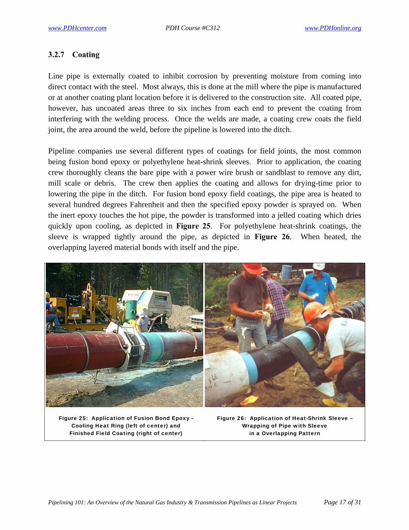
3.2.7 Coating Line pipe is externally coated to inhibit corrosion by preventing moisture from coming into direct contact with the steel. Most always, this is done at the mill where the pipe is manufactured or at another coating plant location before it is delivered to the construction site. All coated pipe, however, has uncoated areas three to six inches from each end to prevent the coating from interfering with the welding process. Once the welds are made, a coating crew coats the field joint, the area around the weld, before the pipeline is lowered into the ditch. Pipeline companies use several different types of coatings for field joints, the most common being fusion bond epoxy or polyethylene heat-shrink sleeves. Prior to application, the coating crew thoroughly cleans the bare pipe with a power wire brush or sandblast to remove any dirt, mill scale or debris. The crew then applies the coating and allows for drying-time prior to lowering the pipe in the ditch. For fusion bond epoxy field coatings, the pipe area is heated to several hundred degrees Fahrenheit and then the specified epoxy powder is sprayed on. When the inert epoxy touches the hot pipe, the powder is transformed into a jelled coating which dries quickly upon cooling, as depicted in Figure 25. For polyethylene heat-shrink coatings, the sleeve is wrapped tightly around the pipe, as depicted in Figure 26. When heated, the overlapping layered material bonds with itself and the pipe.
Figure 25: Application of Fusion Bond Epoxy - Cooling Heat Ring (left of center) and
Finished Field Coating (right of center)
Figure 26: Application of Heat-Shrink Sleeve – Wrapping of Pipe with Sleeve
in a Overlapping Pattern

www.PDHcenter.com PDH Course #C312 www.PDHonline.org
Pipelining 101: An Overview of the Natural Gas Industry & Transmission Pipelines as Linear Projects Page 18 of 31
Prior to lowering-in the pipe into the trench, the coating of the entire pipeline is inspected to ensure that it is free of any defects. This procedure is known as “jeeping”, due to the warning sound the testing equipment makes when a defect or “holiday” is found. 3.2.8 Lowering-In Lowering the welded pipe into the trench demands close coordination between skilled operators. Using a series of side-booms, which are tracked construction equipment with a boom on the side, operators simultaneously lift the pipe and carefully lower the welded sections into the trench (see Figures 27 & 28). Non-metallic slings protect the pipe and coating as it is lifted and moved into position. In rocky areas the contractor may place sandbags or foam blocks at the bottom of the trench prior to lowering-in to protect the pipe and coating from damage.
Figure 27: Sidebooms Lowering-In Pipeline
Figure 28: Sidebooms with Counter-Weights Fully Extended Holding a Heavy Load
3.2.9 Backfilling Now that the pipe has been placed in the trench, the backfilling of the trench can begin. This is usually accomplished with either a backhoe or padding machine depending on the soil makeup. In rocky soils, a padding machine is typically utilized for shifting so that only the finer material is placed upon the pipeline (see Figures 29 & 30). In extremely rocky areas, suitable backfill material may have to be imported for placement directly around the pipeline and/or a “rock shield” wrap-around type protective barrier may be installed to cover the pipeline. As with previous construction crews, the backfilling crew takes care to protect the pipe and coating as the soil is returned to the trench. As the operations begin, the soil is returned to the

www.PDHcenter.com PDH Course #C312 www.PDHonline.org
Pipelining 101: An Overview of the Natural Gas Industry & Transmission Pipelines as Linear Projects Page 19 of 31
trench in reverse order, with the subsoil put back first, followed by the topsoil. This helps ensure that the topsoil is returned to its original position. In areas where the ground is rocky and coarse, crews screen the backfill material to remove rocks, or bring in clean fill to cover the pipe, or the pipe is covered with a material known as “rock-shield” to protect it from sharp rocks. Once the pipe is sufficiently covered the coarser soil and rock can be used to complete the backfill.
Figure 29: “Ozzie” Type Padding Machine Self Feeds from the Spoil Pile
Figure 30: “Dyndopad” Type Padding Machine is Manually Fed by Backhoe
3.2.10 Hydrostatic Testing After completion of the construction steps described above, but before the pipeline is put into operational service, the entire length of the pipeline is pressure tested using water. The hydrostatic test is the final construction quality assurance test. Requirements for this test are also prescribed in the DOT’s federal regulations. Depending on the varying elevation of the terrain along the pipeline and the location of available water sources, the pipeline may be divided into sections to facilitate the test. Each section is filled with water and pressured up to a level higher than the maximum pressure the pipeline will be operated at. The test pressure is held for a specific period of time to determine if it meets the design strength requirements and if any leaks are present. Once a test section successfully passes the hydrostatic test, water is emptied from the pipeline in accordance with state and federal requirements. The pipeline is then dried to ensure it has no water in it before gas is put into the pipeline.
www.PDHcenter.com PDH Course #C312 www.PDHonline.org
Pipelining 101: An Overview of the Natural Gas Industry & Transmission Pipelines as Linear Projects Page 20 of 31
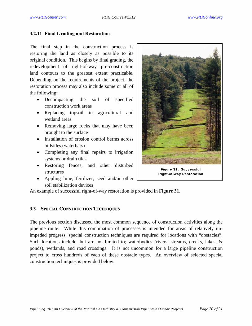
3.2.11 Final Grading and Restoration The final step in the construction process is restoring the land as closely as possible to its original condition. This begins by final grading, the redevelopment of right-of-way pre-construction land contours to the greatest extent practicable. Depending on the requirements of the project, the restoration process may also include some or all of the following:
• Decompacting the soil of specified construction work areas
• Replacing topsoil in agricultural and wetland areas
• Removing large rocks that may have been brought to the surface
• Installation of erosion control berms across hillsides (waterbars)
• Completing any final repairs to irrigation systems or drain tiles
• Restoring fences, and other disturbed structures
• Appling lime, fertilizer, seed and/or other soil stabilization devices
An example of successful right-of-way restoration is provided in Figure 31. 3.3 SPECIAL CONSTRUCTION TECHNIQUES The previous section discussed the most common sequence of construction activities along the pipeline route. While this combination of processes is intended for areas of relatively un-impeded progress, special construction techniques are required for locations with “obstacles”. Such locations include, but are not limited to; waterbodies (rivers, streams, creeks, lakes, & ponds), wetlands, and road crossings. It is not uncommon for a large pipeline construction project to cross hundreds of each of these obstacle types. An overview of selected special construction techniques is provided below.
Figure 31: Successful Right-of-Way Restoration

www.PDHcenter.com PDH Course #C312 www.PDHonline.org
Pipelining 101: An Overview of the Natural Gas Industry & Transmission Pipelines as Linear Projects Page 21 of 31
3.3.1 Waterbody Crossings – Open Cut The “open cut” or “wet” waterbody crossing method involves excavating a trench across the bottom of the river or stream to be crossed with the pipeline (see Figures 32 & 33). Depending on the depth of the water, the construction equipment may have to be placed on barges or other floating platforms to excavate the pipe trench. The contractor prepares the pipe for the crossing by stringing it out on one side of the stream or river and then welding, coating and hydrostatically testing the entire pipe segment. Sidebooms then carry the pipe segment into the streambed, similar to construction on land, or the construction crew floats the pipe into the river with flotation devices and positions it for burial in the trench. Concrete weights or concrete coating ensures the pipe will stay in position at the bottom of the trench once the contractor removes the flotation devices. While this waterbody crossing technique was widely utilized during the early days of pipeline construction, it is now considered to be the most environmentally damaging of the current available construction methods. As such, it is typically selected as a “last resort option” when other available waterbody crossing options are not feasible. Common site constraints that accompany the necessity for open-cut crossings include:
• Unstable geologic substrate, thus prohibiting the use of horizontal directional drilling; &, • High waterbody flows, thus prohibiting water diversion strategies.
Figure 32: Open-Cut Waterbody Crossing - Backhoe Excavating River Bed
Figure 33: Open-Cut Waterbody Crossing - Backhoe Transferring Material in Relay
3.3.2 Waterbody Crossings – Dry Cut The “dry cut” waterbody crossing method is an environmentally friendly variation of the open cut technique. In short, the water flow is diverted through the construction work area within

www.PDHcenter.com PDH Course #C312 www.PDHonline.org
Pipelining 101: An Overview of the Natural Gas Industry & Transmission Pipelines as Linear Projects Page 22 of 31
some type of containment device, typically hard pipes and/or pump hoses. This allows the waterbody flow to continue unimpeded without introducing the adverse impacts of a flooded pipeline trench excavation. While dry-cut crossing designs vary widely, they are typically a function of flow volumes. In all cases, additional dewatering the excavated trench line is usually required to remove accumulated ground water. The groundwater volume is usually small in comparison to the waterbody flow and is pumped to a sediment / turbidity control device prior to discharge. Typical dry-cut crossing design layouts for various flow regimes are summarized below:
Table 2: Typical Dry-Cut Crossing Design Layouts for Various Flow Regimes Flow
Regime Waterbody
Type Design Layout
Low Small streams & creeks
Typical design – “pump around” Low flows can easily be diverted using small diameter hose trash pumps. Upstream of the work zone, a coffer dam of sand bags is created with a sump area to facilitate the pump’s suction intake of the accumulating stream flow. The pumping system discharges well downstream of the work zone to prevent backflow into the excavation. The hoses can be moved around in the work area as needed throughout the construction process.
Medium Average
streams, creeks, & small rivers
Typical design – “flumed crossing” Medium flows are most often diverted using a simple flumed crossing (see Figure 34). A steel flume pipe is placed along the stream bed and centered over the proposed pipeline trench. Sand bag coffer dam(s) are constructed upstream and sometimes downstream of the proposed trenchline thus sealing the flume end(s) with the banks. The proposed trenchline area is then dewatered, as needed based on channel slope, to facilitate excavation, pipe installation, and backfilling. Once construction is complete, the flume and sand bags are removed to allow the waterbody to resume normal flow.
High Large streams, creeks, up to
average rivers
Typical design – “custom flumed crossing” High flows are generally diverted using a custom flumed crossing, which is a structurally enhanced version of the simple flumed crossing. While the concept is the same, a flume assembly consisting one or more larger flumes with welded steel plate end walls is constructed (see Figures 35, 36, & 37). Once the flume assembly is in placed along the stream bed and centered over the proposed pipeline trench, additional steel sheets are imbedded into the waterbody floor and banks to seal off the flow. The area between the steel barriers is then dewatered to facilitate excavation, pipe installation, and backfilling. Once construction is complete, the flume and sand bags are removed to allow the waterbody to resume normal flow.

www.PDHcenter.com PDH Course #C312 www.PDHonline.org
Pipelining 101: An Overview of the Natural Gas Industry & Transmission Pipelines as Linear Projects Page 23 of 31
Figure 34: Simple Flumed Dry-Cut Waterbody Crossing with Upstream Coffer Dam
Figure 35: Custom Flumed Dry-Cut Waterbody Crossing with Excavation Ready to Begin
Figure 36: Fabrication of Dual Flume Assembly
Figure 37: Functioning Dual Flume Assembly - River Entering Flumes (upper right)
- Excavated Pipeline Trench (lower left)
3.3.3 Waterbody Crossings – Horizontal Directional Drilling Horizontal directional drilling, or HDD, is a relatively new technology utilized in the installation of underground utilities, such as gas pipelines, water lines, and fiber optic cables. As the name implies, a pathway is precisely drilled in a primarily horizontal direction using specialized equipment with the primary intent of avoiding obstacle(s) located on the surface or underground. HDDs are typically considered for longer crossings and may reach lengths of several thousand feet. Once complete, the desired utility component is pulled through the new conveyance. This process has many advantages over traditional construction methodologies, including:

www.PDHcenter.com PDH Course #C312 www.PDHonline.org
Pipelining 101: An Overview of the Natural Gas Industry & Transmission Pipelines as Linear Projects Page 24 of 31
• Avoids trenching or extensive site excavation along the proposed route; • Can be used in a localized manner through solid rock; • Avoids obstacles such as large roads, railroads, rivers, small lakes, and environmentally
sensitive areas; and, • Prevents service interruptions to vehicular, rail, and marine traffic.
Notwithstanding the benefits, HDDs cannot be utilized in all locations and requires specific geological conditions throughout the crossing profile. Before a directional drill can be designed, core samples must be taken at least on both sides of the crossing and preferably along the entire planned route to evaluate the underground rock and sand formations. If the subsurface will support a directional drill, the engineer can design a crossing that establishes the entry point, the exit point of the pipeline crossing, and its profile as it would traverse underground to avoid the desired obstacles. The development of an HDD entails three main activities; drilling the profile hole, enlarging the bore hole, and installing the pipeline. These activities are detailed below. Drilling the Profile Hole A small diameter pilot hole is drilled under directional control to a predetermined path using a mud-motor or jet bit on the end of the pilot string for steering (see Figure 38). During this process, a slurry of bentinite and water is forced down the hollow drill shaft to the cutting head area. The introduction of this fluid to the bore hole has three primary purposes; to aid in steering, cooling of the cutting head, and a bore hole cleaning mechanism as the cuttings are flushed back to the surface. Once the pilot string is drilled through to the destination point, the process of bore hole enlargement can begin.
Figure 38: HDD Pilot Hole Drilling

www.PDHcenter.com PDH Course #C312 www.PDHonline.org
Pipelining 101: An Overview of the Natural Gas Industry & Transmission Pipelines as Linear Projects Page 25 of 31
Enlarging the Bore Hole Bore hole reaming operations are carried out to enlarge the drilled hole to a size suitable for accepting the product pipe. Once the initial pilot hole has been established, the pilot head is removed and a larger bore cutting head is installed to the drill stem in the reverse direction (see Figures 39, 40, & 41). The drill rig then ream-pulls this assembly towards itself enlarging the hole. Once the reamer has reached the drill rig, the cutting head is replaced with a slightly larger one, again installed in the reverse direction and ream-pushed to the opposite side. Depending upon the pipe diameter to be installed, numerous back and forth reaming operations may be necessary, each progressively enlarging the hole.
Figure 39: HDD Bore Hole Reaming
Figure 40: New Reamer Ready for Maiden Voyage
Figure 41: Active HDD Rig

www.PDHcenter.com PDH Course #C312 www.PDHonline.org
Pipelining 101: An Overview of the Natural Gas Industry & Transmission Pipelines as Linear Projects Page 26 of 31
Installing the Pipe While the reaming is in progress, the line pipe sections are strung out on the far side of the crossing, opposite of the drilling, to be welded. Once welded the joints are X-rayed, coated, hydrostatically tested and then placed on rollers in preparation for being pulled back through the drilled out hole. Upon completion of the drilling operation, the cutting head is removed and the drill string is attached to the pull-back assembly containing:
1. Cleaning reamer; 2. Swivel joint (to prevent pipe rotation); 3. Pipeline towhead; and the, 4. Welded pipeline segment
The crew uses the drilling rig to pull the pipeline segment back through the drilled hole, where it then is connected into the pipeline on both ends (see Figure 42). The drilling fluid consisting of water and clay minerals will remain in the annulus and protect the pipe.
Figure 42: HDD Pipe Pulling
3.3.4 Wetland Crossings Pipelining in wetlands or marshes requires special construction techniques. For most wetland areas the conventional methods is utilized, while flooded or super-saturated soil conditions requires the use of the push-pull method. The methodologies are detailed below. Conventional Wetland Construction Method The conventional wetland construction method is different from upland pipeline construction in two primary ways; heavy equipment support is necessary and excavated soils are segregated. Crews typically place large timber mats or log rip-rap ahead of the construction equipment to provide a stable working and travel platform (see Figure 11). This stabilized platform acts much

www.PDHcenter.com PDH Course #C312 www.PDHonline.org
Pipelining 101: An Overview of the Natural Gas Industry & Transmission Pipelines as Linear Projects Page 27 of 31
like snowshoes, spreading the weight of the construction equipment over a broad area. The support makes it possible to operate the heavy equipment on the unstable soils to facilitate pipeline installation. Additionally, during the trenching process excavated materials are segregated. Specifically, wetland organic soils containing roots and seeds are piled separately from the underlying mineral soil pile (see Figure 43). Project specific permit requirements may also stipulate the use of a separation layer of hay, straw, and/or other materials between the excavated material and the undisturbed wetland plants and soil below. During the backfilling process, the separation layer is a visual guide to the backhoe operator as to the bottom the spoil piles to prevent digging into the undisturbed area beneath. Mineral soils are replaced to the pipeline trench first with the organic soils returned as the upper layer. The segregation of soils helps ensure a successful restoration of post-construction wetland areas.
Figure 43
Push-Pull Wetland Construction Method In wetlands with flooded or super-saturated soil conditions, travel through the work zone may be prohibited or highly restricted. While excavation and backfilling of the pipeline trench are still required, these work efforts may be accomplished using floating backhoes (see Figure 15), drag-lines, or in shallow conditions conventional backhoes working on a small number of timber mats and leapfrogging the supports along as they work. Pipeline preparation activities including stringing, welding, and coating are conducted in the adjacent upland area in a segmented fashion with relatively short sections fully prepared on a
www.PDHcenter.com PDH Course #C312 www.PDHonline.org
Pipelining 101: An Overview of the Natural Gas Industry & Transmission Pipelines as Linear Projects Page 28 of 31
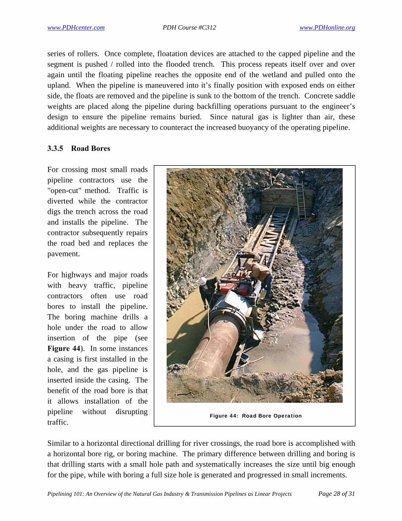
series of rollers. Once complete, floatation devices are attached to the capped pipeline and the segment is pushed / rolled into the flooded trench. This process repeats itself over and over again until the floating pipeline reaches the opposite end of the wetland and pulled onto the upland. When the pipeline is maneuvered into it’s finally position with exposed ends on either side, the floats are removed and the pipeline is sunk to the bottom of the trench. Concrete saddle weights are placed along the pipeline during backfilling operations pursuant to the engineer’s design to ensure the pipeline remains buried. Since natural gas is lighter than air, these additional weights are necessary to counteract the increased buoyancy of the operating pipeline. 3.3.5 Road Bores For crossing most small roads pipeline contractors use the "open-cut" method. Traffic is diverted while the contractor digs the trench across the road and installs the pipeline. The contractor subsequently repairs the road bed and replaces the pavement. For highways and major roads with heavy traffic, pipeline contractors often use road bores to install the pipeline. The boring machine drills a hole under the road to allow insertion of the pipe (see Figure 44). In some instances a casing is first installed in the hole, and the gas pipeline is inserted inside the casing. The benefit of the road bore is that it allows installation of the pipeline without disrupting traffic. Similar to a horizontal directional drilling for river crossings, the road bore is accomplished with a horizontal bore rig, or boring machine. The primary difference between drilling and boring is that drilling starts with a small hole path and systematically increases the size until big enough for the pipe, while with boring a full size hole is generated and progressed in small increments.
Figure 44: Road Bore Operation

www.PDHcenter.com PDH Course #C312 www.PDHonline.org
Pipelining 101: An Overview of the Natural Gas Industry & Transmission Pipelines as Linear Projects Page 29 of 31
4.0 REFERENCES “Acronyms.” FERC: Help – Acronyms. 8 August 2008.
<http://www.ferc.gov/help/acronyms.asp> “Clearing and Grading for Pipeline Construction.” INGAA – Clearing and Grading for Pipeline
Construction. 8 August 2008. <http://www.ingaa.org/cms/33/1339/65/67.aspx> “Coating the Pipeline.” INGAA – Coating the Pipeline. 8 August 2008.
<http://www.ingaa.org/cms/33/1339/65/77.aspx> “Depositing the Pipeline and Backfilling.” INGAA – Depositing the Pipeline and Backfilling. 8
August 2008. <http://www.ingaa.org/cms/33/1339/65/80.aspx> “Fact Sheet: Distribution Pipelines.” PHMSA Stakeholder Communications: Fact Sheet –
Distribution Pipelines. 8 August 2008. <http://primis.phmsa.dot.gov/comm/FactSheets/FSDistributionPipelines.htm>
“Fact Sheet: Gathering Pipelines.” PHMSA Stakeholder Communications: Fact Sheet –
Gathering Pipelines. 8 August 2008. <http://primis.phmsa.dot.gov/comm/FactSheets/FSGatheringPipelines.htm>
“Fact Sheet: Transmission Pipelines.” PHMSA Stakeholder Communications: Fact Sheet –
Transmission Pipelines. 8 August 2008. <http://primis.phmsa.dot.gov/comm/FactSheet/FSTransmissionPipelines.htm>
“How are Pipelines Built?” INGAA – How are Pipelines Built?. 8 August 2008.
<http://www.ingaa.org/cms/33/1339/65.aspx> “How are Pipelines Regulated?” INGAA – How are Pipelines Regulated?. 8 August 2008.
<http://www.ingaa.org/Default.aspx?Id=143> “Hydrostatic Testing.” INGAA – Hydrostatic Testing. 8 August 2008.
<http://www,ingaa.org/cms/33/1339/65/82.aspx> “Interstate Natural Gas Pipelines.” Map. NaturalGas.com. 8 August 2008.
<http://www.naturalgas.org/naturalgas/transport.asp> “List of Countries by Natural Gas Consumption.” Chart. List of countries by natural gas
consumption – Wikipedia, the free encyclopedia. 8 August 2008. <http://en.wikipedia.org/wiki/List-of_countries_by_natural_gas_consumption>

www.PDHcenter.com PDH Course #C312 www.PDHonline.org
Pipelining 101: An Overview of the Natural Gas Industry & Transmission Pipelines as Linear Projects Page 30 of 31
“LNG Tanker History.” Graphic. LNG Tankers. 8 August 2008. <http://www.globalsecurity.org/military/systems/ship/tanker-lng-history.htm>
“The Formation of Natural Gas.” NaturalGas.com. 8 August 2008.
<http://www.naturalgas.org/overview/background.asp> “The Global Liquefied Natural Gas Market: Status and Outlook.” EIA – The Global Liquefied
Natural Gas Market: Status and Outlook – What is Liquefied Gas?. 8 August 2008. <http://www.eai.doe.gov/oiaf/analysispaper/global/lng.html>
“The Natural Gas Industry.” Graphic. Nonrenewable Energy – Natural Gas. 8 August 2008.
<http://www.eia.doe.gov/kids/energyfacts/sources/non-renewable/naturalgas.html> “Petroleum & Natural Gas Formation.” Graphic. Nonrenewable Energy – Natural Gas. 8 August
2008. <http://www.eia.doe.gov/kids/energyfacts/sources/non-renewable/naturalgas.html> “Pipelines 101.” INGAA – Pipelines 101. 8 August 2008.
<http://www.ingaa.org/cms/33/1339.aspx> “Pipeline Basics.” PHMSA Stakeholder Communications: Pipeline Basics. 8 August 2008.
<http://primis.phmsa.dot.gov/comm/PipelinsBasics.htm> “Processes for Natural Gas Certificates – Applicant’s Planning Process.” Graphic. FERC:
Process for Natural Gas Certificates – Applicant’s Planning Process. 8 August 2008. <http://www.ferc.gov/help/processes/flow/gas-1.asp>
“Processes for Natural Gas Certificates – Construction Process.” Graphic. FERC: Processes for
Natural Gas Certificates – Construction Process. 8 August 2008. <http://www.ferc.gov/help/processes/flow/gas-3.asp>
“Processes for Natural Gas Certificates – Environmental Pre-Filing Process.” Graphic. FERC:
Processes for Natural Gas Certificates – Environmental Pre-Filing Process. 8 August 2008. <http://www.ferc.gov/help/processes/flow/gas-4.asp>
“Processes for Natural Gas Certificates – Traditional FERC Process.” Graphic. FERC: Processes
for Natural Gas Certificates – Traditional FERC Process. 8 August 2008. <http://www.ferc.gov/help/processes/flow/gas-2.asp>
“Restoration of the Right of Way.” INGAA – Restoration of the Right of Way. 8 August 2008.
<http://www.ingaa.org/cms/33/1339/65/84.aspx>
www.PDHcenter.com PDH Course #C312 www.PDHonline.org
Pipelining 101: An Overview of the Natural Gas Industry & Transmission Pipelines as Linear Projects Page 31 of 31
“Siting and Right of Way for Interstate Pipelines.” INGAA – Siting and Right of Way for Interstate Pipelines. 8 August 2008. <http://www.ingaa.org/cms/33/1339/65/87.aspx>
Southern Gas Association Environmental Committee. A Layman’s Guide to Environmental
Regulations in the Natural Gas Industry. Dallas, TX: SGA, 2002. “Stringing, Welding and Coating Pipeline Segments.” INGAA – Stringing, Welding and Coating
Pipeline Segments. 8 August 2008. <http://www.ingaa.org/cms/33/1339/65/70.aspx> “Technique.” LMR Drilling UK Ltd – Technique. 8 August 2008.
<http://www/lmrdrilling.co.uk/technique.html> “Trenching for New Pipelines.” INGAA – Trenching for New Pipelines. 8 August 2008.
<http://www.ingaa.org/cms/33/1339/65/73.aspx>

www.PDHcenter.com PDH Course # www.PDHonline.org
ATTACHMENT A
PIPELINE INDUSTRY ACRONYMS

NATURAL GAS INDUSTRY ACRONYMS
Attachment A - Page 1 of 8
401 WQC Section 401 Water Quality Certification A G&T Generation of Transmission Cooperative A&G Administrative and General Expenses AAQS Ambient Air Quality Standards ABF Aquatic Base Flow AC Alternating current ACA Annual Charge Adjustment ACE Area Control Error ACHP Advisory Council on Historic Preservation ACRS Accelerated Cost Recovery System ADIT Accumulated Deferred Income Taxes ADITC Accumulated Deferred Investment Tax Credit ADR Asset Depreciation Range or Alternative Dispute Resolution AFE Authority for Expenditure or Authorization for Expenditure AFUDC Allowance for Funds Used During Construction AGA American Gas Association AGC Automatic Generation Control AGD Associated Gas Distributors AI Agricultural Inspector AIMA Agricultural Impact Mitigation Agreement AIRFA American Indian Religious Freedom Act ALJ Administrative Law Judge AMI Advance Metering Infrastructure ANGTA Alaskan Natural Gas Transportation Act of 1976 ANGTS Alaskan Natural Gas Transportation System ANSI American National Standars Institute
AOS Authorized Overrun Service APA Administrative Procedure Act or Alaska Power Administration APE Area of potential effect API The American Petroleum Institute APPA American Public Power Association AQCR Air Quality Control Region ARPA Archeological Resources Protection Act A/S Ancillary Services ASAL Atlantic salmon population model developed by FWS ASCC (Affiliate) Alaskan System Coordination Council ASRSC Atlantic Sea-Run Salmon Commission ATC Available Transfer Capability BA Balancing Authority BA Biological Assessment BACT Best Available Control Technology BCD Barrels per Calendar Day Bcf Billion Cubic Feet BCP Blackstart Capability Plan BES Bulk Electric System BIA Bureau of Indian Affairs BLM Bureau of Land Management BLM Bureau of Land Management, The Dept. of Interior BPA Bonneville Power Administration BPR Bureau of Parks and Recreation BPS Bulk-Power System BS&W Bottom sediments of water BTU British Thermal Unit
NATURAL GAS INDUSTRY ACRONYMS
Attachment A - Page 2 of 8
BuRec Bureau of Reclamation CAA Clean Air Act CAISO California Independent System Operator Corporation CAP Capacity Market Programs CAPM Capital Asset Pricing Model CBM Capacity Benefit Margin CD Contract Demand CD Certificate of Deposit CEO Chief Executive Officer CEQ Council on Environmental Quality CERCLA Comprehensive Environmental Response, Compensation, and Liability Act CERCLIS Comprehensive Environmental Response, Compensation, and Liability Information System Certificate Certificate of Public Convenience and Necessity cf Cubic Feet Cf Compare CfD Contracts for Differences CFO Chief Financial Officer CFR Code of Federal Regulations CFTC Commodity Future Trade Commission cfs Cubic Feet Per Second CIAC Contribution of Aid of Construction CMVE Competitive Market Value Estimate CNG Compressed Natural Gas CO Carbon Monoxide CO2 Carbon Dioxide COC Cost of Capital COO Chief Operating Officer
COE U.S. Army Corps of Engineers CP Coincident Peak CP Certificate Proceeding CPI Consumer Price Index CPP Critical Peak Pricing cps Cycles Per Second CPS Control Performance Standard CRMP Cultural Resource Management Plans CRP Conservation Reserve Program CRT Capacity Reservation Tariff CSP Curtailment Service Provider CWA Clean Water Act CWIP Construction Work In Progress CZMA Coastal Zone Management Act D.B.A. Doing business as dBA Decibles on the A-weighted scale DBH Diameter Breast Height dc Direct Current DCLM Direct Control Load Management DCS Disturbance Control Standard Decontrol Act Natural Gas Wellhead Decontrol Act DEIS Draft Environmental Impact Statement DF Distribution Factor DFG Department of Fish and Game DLC Direct Load Control DME Disturbance Monitoring Equipment DO Dissolved Oxygen DOE Department of Energy

NATURAL GAS INDUSTRY ACRONYMS
Attachment A - Page 3 of 8
DOE Act Department of Energy Organization Act DOE/FE Department of Energy - Office of Fossil Energy DOI Department of Interior DOT Department of Transportation DR Demand Response DSM Demand-Side Management Dth Dekatherm (equivalent to 1 MMBTU) e.g. Exempli gratia E&D Expenses Exploration and development expenses EA Environmental Assessment EBB Electronic Bulletin Board ECAR East Central Area Reliability Coordination Agreement ECPA Electric Consumers Protection Act EDRP Emergency Demand Response Program EEI Edison Electric Institute EHV Extra High Voltage EI Environmental Inspector EIA Energy Information Administration of the Department of Energy EIS Environmental Impact Statement ELCON Electricity Consumers Resources Council EMF Electro Magnetic Fields EPA Environmental Protection Act EPAct National Energy Policy Act of 1992 EPAct 2005 Energy Policy Act of 2005 EPRI Electric Power Research Institute EPS Earnings Per Share EQR Electric Quarterly Report
ERA Economic Regulatory Administration (now called Fossil Energy FE) ERCOT Electric Reliability Council of Texas ERO Electric Reliability Organization ERTA Economic Recovery Tax Act of 1981 ESA Endangered Species Act ESCO Efficiency Service Company ESOT Employee Stock Ownership Trust EWG Exempt Wholesale Generator FAC Fuel Adjustment Clause FACTS Flexible Alternating Current Transmission System FASB The Financial Accounting Standards Board FCITC First Contingency Incremental Transfer Capability FEIS Final Environmental Impact Statement FELCC Firm Energy Load Carrying Capability FERC or Commission Federal Energy Regulatory Commission FIFO First-in, first-out Fishway Fish Ladder FLPMA Federal Land Policy and Management Act FOIA Freedom of Information Act FONSI Finding of no significant impact FPA Federal Power Act FPC Federal Power Commission FPS Firm peaking service FR Full Requirements FR or F.R. or Fed Reg Federal Register FRCC Florida Reliability Coordinating Council FS Forest Service

NATURAL GAS INDUSTRY ACRONYMS
Attachment A - Page 4 of 8
FSO4 Final Standard Offer Four FT Firm Transportation Service FTC Federal Trade Commission FTR Firm Transmission Rights FTS Firm transportation service FUA The Fuel Use Act FUCO Foreign Utility Company FWPA Federal Water Power Act FWS U.S. Fish and Wildlife Service GAAP Generally Accepted Accounting Principles GATT General Agreement on Tariffs and Trade Genco Generation Company GIC Gas Inventory Charge GISB Gas Industry Standards Board (now NAESB) GLDF Generator-to-Load Distribution Factor GRI Gas Research Institute Gridco Transmission Company (a Transco) GSF Generator-to-Load Distribution Factor GSR Gas Supply Realignment GSR costs Gas Supply Realignment Costs GT&C General terms and conditions GTI Gas Technology Institute GW Gigawatt Gwh Gigawatt-Hour HCA Host Control Area HEP Habitat Evaluation Procedure HHI Hirschman Herfindahl Index HQI Habitat Quality Index hp Horsepower
HVAR Highly Valued Aquatic Resource IBC International Boundary Commission IBES Institutional Brokers' Estimate System ICAP Installed Capacity ICT Independent Coordinator of Transmission IDC Interchange Distribution Calculator IEEE Institute of Electrical and Electronics Engineers, Inc. IER Incremental Energy Rate IFIM Instream Flow Incremental Methodology IGIC Interim gas inventory charge IGSC Interim gas supply charge IGT Institute of Gas Technology IHR Incremental Heat Rate IJC International Joint Commission ILP Integrated Licensing Process IOS Interconnected Operations Services IOU Investor Owned Utility IP Implementation plan IPAA Independent Petroleum Association of America IPPs Independent Power Producers INGAA Interstate Natural Gas Association of America IROL Interconnection Reliability Operating Limit IRP Integrated Resource Planning IRR Internal Rate of Return IRS Internal Revenue Service ISO Independent System Operator ISO-NE ISO New England, Inc. ISP Incentive Sales Program

NATURAL GAS INDUSTRY ACRONYMS
Attachment A - Page 5 of 8
ISS Interruptible Sales Service IT Interruptible Transportation ITC Investment Tax Credit ITS Interruptible transportation service J.A.S. Joint Association Survey KN Kansas-Nebraska kV Kilovolt KVA Kilovolt-Ampere kvar Kilovar Kw Kilowatt KWH Kilowatt-Hour LBO Leveraged Buyout LDC Local Distribution Company LIBOR The London Interbank Offered Rate of Interest LIFO Last-in, First Out LIHEAP Low-Income Home Energy Assistance Program LNG Liquified Natural Gas LODF Line Outage Distribution Factor LOLE Loss of Load Expectation LPG Liquified Petroleum Gas LPN Lender Participation Notes LSE Load Serving Entity LSF Load Shift Factor lsfo Low-sulfur fuel oil MAAC Mid-Atlantic Area Council MAIN Mid-America Interconnected Network MAOP Maximum allowable operating pressure MAPP Mid-Continent Area Power Pool
MBR Market-based Rates Mcf One Thousand Cubic Feet MDD Maximum Daily Delivery Obligations MDDQ Maximum Daily Delivery Quantity MDQ Maximum Daily Quantities MER Maximum Efficient Rate MFV Modified Fixed-Variable Rate MISO Midwest Independent Transmission System Operator, Inc. MLP Maximum lawful price MLRA Major Land Resource Areas MM Used to denote million in gas usage MMBtu 1 million British Thermal Unit MMC Market Monitoring Center MMcf 1 million cubic feet of gas MMS Mineral Management Service MODFLOW model of groundwater flow MOU Memorandum of Understanding MP Milepost MRO Midwest Reliability Organization msl Mean sea level MSW Municipal Solid Waste Muni Municipality MVA Megavolt-Amperes MW Megawatts NAAQS National Ambient Air Quality Standards NAESB North American Energy Standards Board (formerly GISB) NAFTA North American Free Trade Agreement NARUC National Association of Regulatory Utility Commissioners
NATURAL GAS INDUSTRY ACRONYMS
Attachment A - Page 6 of 8
NASDAQS National Ass'n of Securities Dealers Automated Quotation Sys. NASUCA National Association of Utility Consumer Advocates NATC Non-Recallable Available Transfer Capability NBS National Bureau of Standards NCD Non-coincidental Demand NCSL National Conference of State Legislatures NEA of 1978 The National Energy Act of 1978 NEB National Energy Board NEPA National Environmental Policy Act NEPOOL New England Power Pool NERC North American Electric Reliability Council NGA Natural Gas Act NGAA Natural Gasoline Association of America NGL Natural Gas Liquids NGPA Natural Gas Policy Act of 1978 NGPSA Natural Gas Pipeline Safety Act of 1968 NGSA Natural Gas Supply Association NHPA National Historic Preservation Act NITC Normal Incremental Transfer Capability NMFS National Marine Fisheries Service NOAA National Oceanic and Atmospheric Administration NOI Notice of Intent or Notice of Inquiry or Notice of Investigation NOPR Notice of Proposed Rulemaking NPCC Northeast Power Coordinating Council NPS National Park Service NPV Net Present Value NRC Nuclear Regulatory Commission
NRCS National Resource Conservation Service NREPA National Resource and Environmental Protection Act NRHP National Register of Historic Places NRI National Rivers Inventory NSA Noise sensitive area NUG Non-Utility Generator NWI National Wetland Inventory NYSDEC New York State Department of Environmental Conservation NYISO New York Independent System Operator, Inc. O&M Operation and Maintenance Expenses OASIS Open Access Same Time Information Systems OATT Open Access Transmission Tariff OC Optical Certificate OCS Outer Continental Shelf OCSLA Outer Continental Shelf Lands Act OFO Operational Flow Order O&M Operation and maintenance OMP Operation and Maintenance Plan Ontario IESO Ontario Independent Electricity System Operator OPEC Organization of Petroleum Exporting Countries OSHA U.S. Department of Labor Occupational Safety and Health Administration OTAG Ozone Transport Assessment Group OTDF Outage Transfer Distribution Factor PA Planning Authority PA Programmatic Agreement PBR Performance-Based Regulation

NATURAL GAS INDUSTRY ACRONYMS
Attachment A - Page 7 of 8
PCB Polychlorinated biphenyls PD Preliminary Determination PGA Purchased Gas Adjustment PHA Production Handling Agreement PHFFU Plant held for future use PIDX Petroleum Industry Data Exchange PIFUA Powerplant and Industrial Fuel Use Act of 1978 PJM PJM Interconnection, LLC Plan FERC's Upland Erosion Control, Revegetation, and Maintenance Plan (when used in gas certificate proceedings) PM Particulate matter PMA Power Marketing Administration or Fed. Power Marketing Agency PM&E Protection, mitigation and enhancement POD Point of Delivery POR Point of Receipt PPA Power Purchase Agreement ppm Parts per million Procedures FERC's Wetland & Waterbody Construction Mitigation Procedures (when used in gas certificate proceedings) PSC Public Service Commission PSD Prevention of Significant Deterioration psig Pounds per square inch PTDF Power Transfer Distribution Factor PTP Point to Point Transmission Service PUC Public Utility Commission PUD Public Utility District PUHCA Public Utility Holding Company Act PURPA Public Utility Regulatory Policies Act
PX Power Exchange QF Qualifying Facility QFs Qualifying Facilities QUAD A quadrillion Btus R/P Reserves-to-Production RAB Regional Advisory Body RAS Remedial Action Scheme RATC Recallable Available Transmission Capability RC Reliability Coordinator RCRA Resource Conservation and Recovery Act RCIS Reliability Coordinator Information System RFA Regulatory Flexibility Act RFC ReliabilityFirst Corporation RFI Request for Interchange RM Rulemaking RMR Reliability Must Run ROA Return of Assets ROE Return of Equity ROFR Right of First Refusal ROI Return on Investment ROW Right-of-Way RPM Reliability Pricing Model RRO Regional Reliability Organization RSE Revenue Stream Estimate RTG Regional Transmission Group RTO Regional Transmission Organization RTP Real-time Pricing RTU Remote Terminal Unit RUS Rural Utilities Service

NATURAL GAS INDUSTRY ACRONYMS
Attachment A - Page 8 of 8
SCADA Supervisory Control and Data Acquisition Scf Standard Cubic Foot of Natural Gas SCO Stranded Cost Obligation SEC Securities and Exchange Commission SERC SERC Reliability Corporation Secretary generally refers to Secretary of the Commission SFEIS Supplemental Final Environmental Impact Statement SFV Straight Fixed-Variable SGR State game refuge SHPO State Historic Preservation Office SIC Standard Industrial Classification SMPs Special Marketing Programs SNG Synthetic Natural Gas or Substitute Natural Gas SOL System Operating Limit SPCC Spill Prevention, Containment and Countermeasure Plan SPP Small Power Producer SPP Southwest Power Pool, Inc. SPS Special Protection System SVC Static VAR Compensator SYD Sum of Years' Digits TBS Town border station TC Total Cost Tcf Trillion cubic feet TCR Transition Cost Recovery (Mechanism) TDU Transmission Dependent Utility TEFRA Tax Equity and Fiscal Responsibility Act of 1985
TLR Procedures Transmission Line Loading Relief Procedures TOP Transmission Operator TOU Time-of-Use Transco Transmission Company TRM Transmission Reliability Margin TTC Total Transfer Capability TVA Tennessee Valley Authority UFLS Under Frequency Load Shedding U.S.C. United States Code USDA U.S. Department of Agriculture USGS U.S. Geological Survey UVLS Under Voltage Load Shedding v. Versus v Volt VA Volt-Ampere VAR Volt-Ampere-Reactive Unit WACOG weighted average cost of gas WECC Western Electricity Coordinating Council WIRAB Western Interconnection Regional Advisory Body WMA Wildlife management area WPA Waterfowl production area WPI Wholesale Price Index WQC Water Quality Certificate WSCC Western Systems Coordinating Council WSPP Western Systems Power Pool WTP Willingness to Pay WY Water Year

www.PDHcenter.com PDH Course # www.PDHonline.org
ATTACHMENT B
FEDERAL ENERGY REGULATORY COMMISSION NATURAL GAS PIPELINE PERMITTING FLOWCHARTS