Pipelined Processor DesignPipelined Datapath Pipeline registers are shown in green , including the...
33
1 Pipelined Processor Design COE 308 Computer Architecture Prof. Muhamed Mudawar Computer Engineering Department King Fahd University of Petroleum and Minerals Pipelined Processor Design COE 308 – Computer Architecture © Muhamed Mudawar – slide 2 Presentation Outline Pipelining versus Serial Execution Pipelined Datapath and Control Pipeline Hazards Data Hazards and Forwarding Load Delay, Hazard Detection, and Stall Control Hazards Delayed Branch and Dynamic Branch Prediction
Transcript of Pipelined Processor DesignPipelined Datapath Pipeline registers are shown in green , including the...

1
Pipelined Processor Design
COE 308Computer Architecture
Prof. Muhamed Mudawar
Computer Engineering Department
King Fahd University of Petroleum and Minerals
Pipelined Processor Design COE 308 – Computer Architecture © Muhamed Mudawar – slide 2
Presentation Outline
� Pipelining versus Serial Execution
� Pipelined Datapath and Control
� Pipeline Hazards
� Data Hazards and Forwarding
� Load Delay, Hazard Detection, and Stall
� Control Hazards
� Delayed Branch and Dynamic Branch Prediction

2
Pipelined Processor Design COE 308 – Computer Architecture © Muhamed Mudawar – slide 3
� Laundry Example: Three Stages
1. Wash dirty load of clothes
2. Dry wet clothes
3. Fold and put clothes into drawers
� Each stage takes 30 minutes to complete
� Four loads of clothes to wash, dry, and fold
A B
C D
Pipelining Example
Pipelined Processor Design COE 308 – Computer Architecture © Muhamed Mudawar – slide 4
� Sequential laundry takes 6 hours for 4 loads
� Intuitively, we can use pipelining to speed up laundry
Sequential Laundry
Time6 PM
A
30 30 30
7 8 9 10 11 12 AM30 30 30
B
30 30 30
C
30 30 30
D

3
Pipelined Processor Design COE 308 – Computer Architecture © Muhamed Mudawar – slide 5
� Pipelined laundry takes 3 hours for 4 loads
� Speedup factor is 2 for 4 loads
� Time to wash, dry, and fold one load is still the same (90 minutes)
Pipelined Laundry: Start Load ASAP
Time
6 PM
A
30
7 8 9 PM
B
3030
C
303030
D
303030
3030 30
Pipelined Processor Design COE 308 – Computer Architecture © Muhamed Mudawar – slide 6
Serial Execution versus Pipelining
� Consider a task that can be divided into k subtasks� The k subtasks are executed on k different stages
� Each subtask requires one time unit
� The total execution time of the task is k time units
� Pipelining is to overlap the execution� The k stages work in parallel on k different tasks
� Tasks enter/leave pipeline at the rate of one task per time unit
1 2 k…
1 2 k…
1 2 k…
1 2 k…
1 2 k…
1 2 k…
Without PipeliningOne completion every k time units
With PipeliningOne completion every 1 time unit

4
Pipelined Processor Design COE 308 – Computer Architecture © Muhamed Mudawar – slide 7
Synchronous Pipeline� Uses clocked registers between stages
� Upon arrival of a clock edge …
� All registers hold the results of previous stages simultaneously
� The pipeline stages are combinational logic circuits
� It is desirable to have balanced stages
� Approximately equal delay in all stages
� Clock period is determined by the maximum stage delay
S1 S2 Sk
Reg
iste
r
Reg
iste
r
Reg
iste
r
Reg
iste
r
Input
Clock
Output
Pipelined Processor Design COE 308 – Computer Architecture © Muhamed Mudawar – slide 8
� Let τi = time delay in stage Si
� Clock cycle τ = max(τi) is the maximum stage delay
� Clock frequency f = 1/τ = 1/max(τi)
� A pipeline can process n tasks in k + n – 1 cycles
� k cycles are needed to complete the first task
� n – 1 cycles are needed to complete the remaining n – 1 tasks
� Ideal speedup of a k-stage pipeline over serial execution
Pipeline Performance
k + n – 1Pipelined execution in cycles
Serial execution in cycles== Sk → k for large n
nkSk
5
Pipelined Processor Design COE 308 – Computer Architecture © Muhamed Mudawar – slide 9
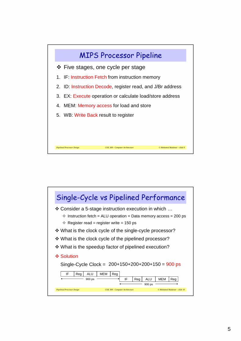
MIPS Processor Pipeline
� Five stages, one cycle per stage
1. IF: Instruction Fetch from instruction memory
2. ID: Instruction Decode, register read, and J/Br address
3. EX: Execute operation or calculate load/store address
4. MEM: Memory access for load and store
5. WB: Write Back result to register
Pipelined Processor Design COE 308 – Computer Architecture © Muhamed Mudawar – slide 10
Single-Cycle vs Pipelined Performance
� Consider a 5-stage instruction execution in which …� Instruction fetch = ALU operation = Data memory access = 200 ps
� Register read = register write = 150 ps
� What is the clock cycle of the single-cycle processor?
� What is the clock cycle of the pipelined processor?
� What is the speedup factor of pipelined execution?
� Solution
Single-Cycle Clock = 200+150+200+200+150 = 900 ps
Reg ALU MEMIF
900 ps
Reg
Reg ALU MEMIF
900 ps
Reg
6
Pipelined Processor Design COE 308 – Computer Architecture © Muhamed Mudawar – slide 11
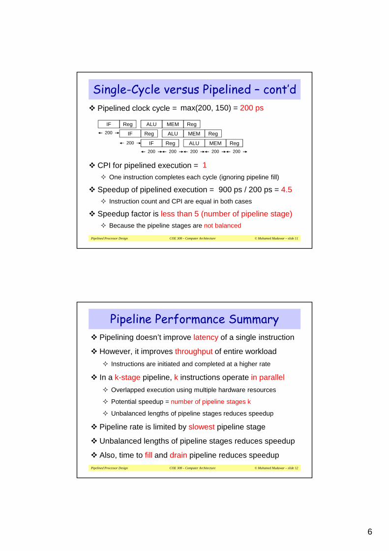
Single-Cycle versus Pipelined – cont’d
� Pipelined clock cycle =
� CPI for pipelined execution = � One instruction completes each cycle (ignoring pipeline fill)
� Speedup of pipelined execution =� Instruction count and CPI are equal in both cases
� Speedup factor is less than 5 (number of pipeline stage)� Because the pipeline stages are not balanced
900 ps / 200 ps = 4.5
1
max(200, 150) = 200 ps
200
IF Reg MEMALU Reg
IF Reg MEM RegALU
IF Reg MEMALU Reg200
200 200 200 200 200
Pipelined Processor Design COE 308 – Computer Architecture © Muhamed Mudawar – slide 12
Pipeline Performance Summary
� Pipelining doesn’t improve latency of a single instruction
� However, it improves throughput of entire workload
� Instructions are initiated and completed at a higher rate
� In a k-stage pipeline, k instructions operate in parallel
� Overlapped execution using multiple hardware resources
� Potential speedup = number of pipeline stages k
� Unbalanced lengths of pipeline stages reduces speedup
� Pipeline rate is limited by slowest pipeline stage
� Unbalanced lengths of pipeline stages reduces speedup
� Also, time to fill and drain pipeline reduces speedup
7
Pipelined Processor Design COE 308 – Computer Architecture © Muhamed Mudawar – slide 13
Next . . .
� Pipelining versus Serial Execution
� Pipelined Datapath and Control
� Pipeline Hazards
� Data Hazards and Forwarding
� Load Delay, Hazard Detection, and Stall
� Control Hazards
� Delayed Branch and Dynamic Branch Prediction
Pipelined Processor Design COE 308 – Computer Architecture © Muhamed Mudawar – slide 14
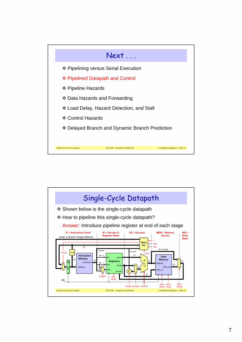
ID = Decode &Register Read
Single-Cycle Datapath� Shown below is the single-cycle datapath
� How to pipeline this single-cycle datapath?
Answer: Introduce pipeline register at end of each stage
Next PC
zeroPCSrc
ALUCtrl
RegWrite
ExtOp
RegDst
ALUSrc
DataMemory
Address
Data_inData_out
32
32ALU
32
Registers
RA
RB
BusA
BusB
RW
5
BusW
32
Address
Instruction
InstructionMemory
PC
00
30
Rs
5
RdE
Imm16
Rt
0
1
0
1
32
Imm26
32
ALU result
32
0
1
clk
+1
0
1
30
Jump or Branch Target Address
MemRead
MemWrite
MemtoReg
EX = ExecuteIF = Instruction Fetch MEM = MemoryAccess
WB =WriteBack
Bne
Beq
J

8
Pipelined Processor Design COE 308 – Computer Architecture © Muhamed Mudawar – slide 15
zero
Pipelined Datapath� Pipeline registers are shown in green, including the PC
� Same clock edge updates all pipeline registers, register file, and data memory (for store instruction)
clk
32
ALU
325
Address
Instruction
InstructionMemory Rs
5Rt 1
0
ALU result
32
0
1
DataMemory
Address
Data_in
Data_out
ID = Decode &Register Read
EX = ExecuteIF = Instruction Fetch MEM = MemoryAccess
WB
= W
rite
Bac
k
32
Reg
iste
r F
ile
RA
RB
BusA
BusBRW
BusW
32
E
Rd
0
1
PC
ALU
out
D
WB
Dat
a
32
Imm16
Imm26
Next PC
AB
Imm
NP
C2
Inst
ruct
ion
NP
C
+1
0
1
Pipelined Processor Design COE 308 – Computer Architecture © Muhamed Mudawar – slide 16
Problem with Register Destination� Is there a problem with the register destination address?
� Instruction in the ID stage different from the one in the WB stage
� Instruction in the WB stage is not writing to its destination register but to the destination of a different instruction in the ID stage
zero
clk
32
ALU
325
Address
Instruction
InstructionMemory Rs
5Rt 1
0
ALU result
32
0
1
DataMemory
Address
Data_in
Data_out
ID = Decode &Register Read EX = ExecuteIF = Instruction Fetch MEM =
Memory Access
WB
= W
rite
Bac
k
32
Reg
iste
r F
ile
RA
RB
BusA
BusBRW
BusW
32
E
Rd
0
1
PC
ALU
out
D
WB
Dat
a
32
Imm16
Imm26
Next PC
AB
Imm
NP
C2
Inst
ruct
ion
NP
C
+1
0
1

9
Pipelined Processor Design COE 308 – Computer Architecture © Muhamed Mudawar – slide 17
Pipelining the Destination Register� Destination Register number should be pipelined
� Destination register number is passed from ID to WB stage
� The WB stage writes back data knowing the destination register
zero
clk
32
ALU
325
Address
Instruction
InstructionMemory Rs
5Rt 1
0
ALU result
32
0
1
DataMemory
Address
Data_in
Data_out
ID EXIF MEM WB
32
Reg
iste
r F
ile
RA
RB
BusA
BusBRW
BusW
32
E
PC
ALU
out
D
WB
Dat
a
32
Imm16
Imm26
Next PC
AB
Imm
NP
C2
Inst
ruct
ion
NP
C
+1
0
1Rd
Rd20
1 Rd3
Rd4
Pipelined Processor Design COE 308 – Computer Architecture © Muhamed Mudawar – slide 18
Graphically Representing Pipelines� Multiple instruction execution over multiple clock cycles
� Instructions are listed in execution order from top to bottom
� Clock cycles move from left to right
� Figure shows the use of resources at each stage and each cycle
Time (in cycles)
Prog
ram
Exec
utio
n O
rder
add $s1, $s2, $s3
CC2
Reg
IM
DM
Reg
sub $t5, $s2, $t3
CC4
ALU
IM
sw $s2, 10($t3)
DM
Reg
CC5
Reg
ALU
IM
DM
Reg
CC6
Reg
ALU DM
CC7
Reg
ALU
CC8
Reg
DM
lw $t6, 8($s5) IM
CC1
Reg
ori $s4, $t3, 7
ALU
CC3
IM

10
Pipelined Processor Design COE 308 – Computer Architecture © Muhamed Mudawar – slide 19
� Instruction-Time Diagram shows:� Which instruction occupying what stage at each clock cycle
� Instruction flow is pipelined over the 5 stages
Instruction-Time Diagram
IF
WB
–
EX
ID
WB
–
EX
WB
MEM –
ID
IF
EX
ID
IF
TimeCC1 CC4 CC5 CC6 CC7 CC8 CC9CC2 CC3
MEM
EX
ID
IF
WB
MEM
EX
ID
IF
lw $t7, 8($s3)
lw $t6, 8($s5)
ori $t4, $s3, 7
sub $s5, $s2, $t3
sw $s2, 10($s3)Inst
ruct
ion
Ord
er
Up to five instructions can be in the pipeline during the same cycle
Instruction Level Parallelism (ILP)
ALU instructions skip the MEM stage.
Store instructions skip the WB stage
Pipelined Processor Design COE 308 – Computer Architecture © Muhamed Mudawar – slide 20
Control Signals
zero
clk
32
ALU
325
Address
Instruction
InstructionMemory Rs
5Rt1
0
ALU result
32
0
1
DataMemory
Address
Data_in
Data_out
32
Reg
iste
r F
ile
RA
RB
BusA
BusBRW
BusW
32
E
PC
ALU
out
D
WB
Dat
a
32
Imm16
Imm26
Next PC
AB
Imm
NP
C2
Inst
ruct
ion
NP
C
+1
0
1Rd
Rd20
1 Rd3
Rd4
Same control signals used in the single-cycle datapath
ALUCtrl
RegWrite
RegDst
ALUSrc
MemWrite
MemtoReg
MemRead
ExtOp
PCSrc
ID EXIF MEM WB
Bne
Beq
J

11
Pipelined Processor Design COE 308 – Computer Architecture © Muhamed Mudawar – slide 21
Pipelined Control
zero
clk
32
ALU
325
Address
Instruction
InstructionMemory Rs
5Rt1
0
ALU result
32
0
1
DataMemory
Address
Data_in
Data_out
32R
egis
ter
File
RA
RB
BusA
BusBRW
BusW
32
E
PC
ALU
out
D
WB
Dat
a
32
Imm16
Imm26
Next PC
AB
Imm
NP
C2
Inst
ruct
ion
NP
C
+1
0
1Rd
Rd20
1 Rd3
Rd4
PCSrc
Bne
Beq
J
Op
RegDst
EX
ALUSrc
ALUCtrl
ExtOp
JBeqBne
ME
M
MemWrite
MemRead
MemtoReg
WB
RegWrite
Pass control signals along pipeline just like the data
Main& ALUControl
func
Pipelined Processor Design COE 308 – Computer Architecture © Muhamed Mudawar – slide 22
Pipelined Control – Cont'd
� ID stage generates all the control signals
� Pipeline the control signals as the instruction moves
� Extend the pipeline registers to include the control signals
� Each stage uses some of the control signals
� Instruction Decode and Register Read
� Control signals are generated
� RegDst is used in this stage
� Execution Stage => ExtOp, ALUSrc, and ALUCtrl
� Next PC uses J, Beq, Bne, and zero signals for branch control
� Memory Stage => MemRead, MemWrite, and MemtoReg
� Write Back Stage => RegWrite is used in this stage

12
Pipelined Processor Design COE 308 – Computer Architecture © Muhamed Mudawar – slide 23
Op
Decode Stage
Execute Stage
Control Signals
Memory Stage
Control Signals
Write
Back
RegDst ALUSrc ExtOp J Beq Bne ALUCtrl MemRd MemWr MemReg RegWrite
R-Type 1=Rd 0=Reg x 0 0 0 func 0 0 0 1
addi 0=Rt 1=Imm 1=sign 0 0 0 ADD 0 0 0 1
slti 0=Rt 1=Imm 1=sign 0 0 0 SLT 0 0 0 1
andi 0=Rt 1=Imm 0=zero 0 0 0 AND 0 0 0 1
ori 0=Rt 1=Imm 0=zero 0 0 0 OR 0 0 0 1
lw 0=Rt 1=Imm 1=sign 0 0 0 ADD 1 0 1 1
sw x 1=Imm 1=sign 0 0 0 ADD 0 1 x 0
beq x 0=Reg x 0 1 0 SUB 0 0 x 0
bne x 0=Reg x 0 0 1 SUB 0 0 x 0
j x x x 1 0 0 x 0 0 x 0
Control Signals Summary
Pipelined Processor Design COE 308 – Computer Architecture © Muhamed Mudawar – slide 24
Next . . .
� Pipelining versus Serial Execution
� Pipelined Datapath and Control
� Pipeline Hazards
� Data Hazards and Forwarding
� Load Delay, Hazard Detection, and Stall
� Control Hazards
� Delayed Branch and Dynamic Branch Prediction

13
Pipelined Processor Design COE 308 – Computer Architecture © Muhamed Mudawar – slide 25
� Hazards: situations that would cause incorrect execution� If next instruction were launched during its designated clock cycle
1. Structural hazards� Caused by resource contention
� Using same resource by two instructions during the same cycle
2. Data hazards� An instruction may compute a result needed by next instruction
� Hardware can detect dependencies between instructions
3. Control hazards� Caused by instructions that change control flow (branches/jumps)
� Delays in changing the flow of control
� Hazards complicate pipeline control and limit performance
Pipeline Hazards
Pipelined Processor Design COE 308 – Computer Architecture © Muhamed Mudawar – slide 26
Structural Hazards� Problem
� Attempt to use the same hardware resource by two different
instructions during the same cycle
� Example� Writing back ALU result in stage 4
� Conflict with writing load data in stage 5
WB
WB
EX
ID
WB
EX MEM
IF ID
IF
TimeCC1 CC4 CC5 CC6 CC7 CC8 CC9CC2 CC3
EX
ID
IF
MEM
EX
ID
IF
lw $t6, 8($s5)
ori $t4, $s3, 7
sub $t5, $s2, $s3
sw $s2, 10($s3)Inst
ruct
ions
Structural HazardTwo instructions are attempting to write
the register file during same cycle

14
Pipelined Processor Design COE 308 – Computer Architecture © Muhamed Mudawar – slide 27
Resolving Structural Hazards� Serious Hazard:
� Hazard cannot be ignored
� Solution 1: Delay Access to Resource
� Must have mechanism to delay instruction access to resource
� Delay all write backs to the register file to stage 5
� ALU instructions bypass stage 4 (memory) without doing anything
� Solution 2: Add more hardware resources (more costly)
� Add more hardware to eliminate the structural hazard
� Redesign the register file to have two write ports
� First write port can be used to write back ALU results in stage 4
� Second write port can be used to write back load data in stage 5
Pipelined Processor Design COE 308 – Computer Architecture © Muhamed Mudawar – slide 28
Next . . .
� Pipelining versus Serial Execution
� Pipelined Datapath and Control
� Pipeline Hazards
� Data Hazards and Forwarding
� Load Delay, Hazard Detection, and Stall
� Control Hazards
� Delayed Branch and Dynamic Branch Prediction

15
Pipelined Processor Design COE 308 – Computer Architecture © Muhamed Mudawar – slide 29
� Dependency between instructions causes a data hazard
� The dependent instructions are close to each other
� Pipelined execution might change the order of operand access
� Read After Write – RAW Hazard
� Given two instructions I and J, where I comes before J
� Instruction J should read an operand after it is written by I
� Called a data dependence in compiler terminology
I: add $s1 , $s2, $s3 # $s1 is written
J: sub $s4, $s1 , $s3 # $s1 is read
� Hazard occurs when J reads the operand before I writes it
Data Hazards
Pipelined Processor Design COE 308 – Computer Architecture © Muhamed Mudawar – slide 30
DMReg
IM
Reg
ALU
IM
DM
Reg
Reg
ALU
IM
DM
Reg
Reg
ALU DM
Reg
ALU
Reg
DM
IM
Reg
ALU
IM
Time (cycles)
Prog
ram
Exec
utio
n O
rder
value of $s2
sub $s2, $t1, $t3
CC110
CC2
add $s4, $s2, $t5
10
CC3
or $s6, $t3, $s2
10
CC4
and $s7, $t4, $s2
10
CC620
CC720
CC820
CC5
sw $t8, 10($s2)
10
Example of a RAW Data Hazard
� Result of sub is needed by add, or, and, & sw instructions
� Instructions add & or will read old value of $s2 from reg file
� During CC5, $s2 is written at end of cycle, old value is read

16
Pipelined Processor Design COE 308 – Computer Architecture © Muhamed Mudawar – slide 31
RegReg
Solution 1: Stalling the Pipeline
� Three stall cycles during CC3 thru CC5 (wasting 3 cycles)
� Stall cycles delay execution of add & fetching of or instruction
� The add instruction cannot read $s2 until beginning of CC6
� The add instruction remains in the Instruction register until CC6
� The PC register is not modified until beginning of CC6
DM
Reg
RegReg
Time (in cycles)
Inst
ruct
ion
Ord
er
value of $s2CC110
CC210
CC310
CC410
CC620
CC720
CC820
CC510
add $s4, $s2, $t5 IM
or $s6, $t3, $s2 IM ALU
ALU Reg
sub $s2, $t1, $t3 IM Reg ALU DM Reg
CC920
stall stallDM
stall
Pipelined Processor Design COE 308 – Computer Architecture © Muhamed Mudawar – slide 32
DM
Reg
Reg
Reg
Reg
Reg
Time (cycles)
Prog
ram
Exec
utio
n O
rder
value of $s2
sub $s2, $t1, $t3 IM
CC110
CC2
add $s4, $s2, $t5 IM
10
CC3
or $s6, $t3, $s2
ALU
IM
10
CC4
and $s7, $s6, $s2
ALU
IM
10
CC6
Reg
DM
ALU
20
CC7
Reg
DM
ALU
20
CC8
Reg
DM
20
CC5
sw $t8, 10($s2)
Reg
DM
ALU
IM
10
Solution 2: Forwarding ALU Result
� The ALU result is forwarded (fed back) to the ALU input� No bubbles are inserted into the pipeline and no cycles are wasted
� ALU result is forwarded from ALU, MEM, and WB stages

17
Pipelined Processor Design COE 308 – Computer Architecture © Muhamed Mudawar – slide 33
Implementing Forwarding
0123
0123
Res
ult
3232
clk
Rd
32
Rs
Inst
ruct
ion
01
ALU result
32
0
1
DataMemory
Address
Data_in
Data_out
32
Rd4
ALUE
Imm16Imm26
1
0
Rd3
Rd2
AB
WD
ata
D
Im26
32
Reg
iste
r F
ile
RB
BusA
BusB
RW BusW
RARt
� Two multiplexers added at the inputs of A & B registers� Data from ALU stage, MEM stage, and WB stage is fed back
� Two signals: ForwardA and ForwardB control forwarding
ForwardA
ForwardB
Pipelined Processor Design COE 308 – Computer Architecture © Muhamed Mudawar – slide 34
Forwarding Control Signals
Signal Explanation
ForwardA = 0 First ALU operand comes from register file = Value of (Rs)
ForwardA = 1 Forward result of previous instruction to A (from ALU stage)
ForwardA = 2 Forward result of 2nd previous instruction to A (from MEM stage)
ForwardA = 3 Forward result of 3rd previous instruction to A (from WB stage)
ForwardB = 0 Second ALU operand comes from register file = Value of (Rt)
ForwardB = 1 Forward result of previous instruction to B (from ALU stage)
ForwardB = 2 Forward result of 2nd previous instruction to B (from MEM stage)
ForwardB = 3 Forward result of 3rd previous instruction to B (from WB stage)

18
Pipelined Processor Design COE 308 – Computer Architecture © Muhamed Mudawar – slide 35
Forwarding Example
Res
ult
3232
clk
Rd
32
Rs
Inst
ruct
ion
01
ALU result
32
0
1
DataMemory
Address
Data_in
Data_out
32
Rd4
ALU
extImm16
Imm26
1
0
Rd3
Rd2
AB
0123
0123
WD
ata
D
Imm
32
Reg
iste
r F
ile
RB
BusA
BusB
RW BusW
RARt
Instruction sequence:lw $t4 , 4($t0)ori $t7 , $t1, 2sub $t3, $t4 , $t7
When sub instruction is fetched
ori will be in the ALU stage
lw will be in the MEM stage
ForwardA = 2 from MEM stage ForwardB = 1 from ALU stage
lw $t4 ,4($t0)ori $t7 ,$t1,2sub $t3, $t4 , $t7
2
1
Pipelined Processor Design COE 308 – Computer Architecture © Muhamed Mudawar – slide 36
RAW Hazard Detection� Current instruction being decoded is in Decode stage
� Previous instruction is in the Execute stage
� Second previous instruction is in the Memory stage
� Third previous instruction in the Write Back stage
If ((Rs != 0) and (Rs == Rd2) and (EX.RegWrite)) ForwardA � 1
Else if ((Rs != 0) and (Rs == Rd3) and (MEM.RegWrite)) ForwardA � 2
Else if ((Rs != 0) and (Rs == Rd4) and (WB.RegWrite)) ForwardA � 3
Else ForwardA � 0
If ((Rt != 0) and (Rt == Rd2) and (EX.RegWrite)) ForwardB � 1
Else if ((Rt != 0) and (Rt == Rd3) and (MEM.RegWrite)) ForwardB � 2
Else if ((Rt != 0) and (Rt == Rd4) and (WB.RegWrite)) ForwardB � 3
Else ForwardB � 0

19
Pipelined Processor Design COE 308 – Computer Architecture © Muhamed Mudawar – slide 37
Hazard Detect and Forward Logic
0123
0123
Res
ult
3232
clk
Rd
32
Rs
01
ALU result
32
0
1
DataMemory
Address
Data_in
Data_out
32
Rd4
ALU
E
Imm26
1
0
Rd3
Rd2
AB W
Dat
a
D
Im26
32
Reg
iste
r F
ileRB
BusA
BusB
RW BusW
RARt
Inst
ruct
ion
ForwardB ForwardA
Hazard Detect
and Forwardfunc
ALUCtrl
RegDst
Main& ALUControl
OpM
EME
X
WB
RegWriteRegWriteRegWrite
Pipelined Processor Design COE 308 – Computer Architecture © Muhamed Mudawar – slide 38
Next . . .
� Pipelining versus Serial Execution
� Pipelined Datapath and Control
� Pipeline Hazards
� Data Hazards and Forwarding
� Load Delay, Hazard Detection, and Pipeline Stall
� Control Hazards
� Delayed Branch and Dynamic Branch Prediction

20
Pipelined Processor Design COE 308 – Computer Architecture © Muhamed Mudawar – slide 39
Reg
Reg
Reg
Time (cycles)
Prog
ram
Ord
er
CC2
add $s4, $s2, $t5
Reg
IF
CC3
or $t6, $t3, $s2
ALU
IF
CC6
Reg
DM
ALU
CC7
Reg
Reg
DM
CC8
Reg
lw $s2, 20($t1) IF
CC1 CC4
and $t7, $s2, $t4
DM
ALU
IF
CC5
DM
ALU
Load Delay� Unfortunately, not all data hazards can be forwarded
� Load has a delay that cannot be eliminated by forwarding
� In the example shown below …� The LW instruction does not read data until end of CC4
� Cannot forward data to ADD at end of CC3 - NOT possible
However, load can forward data to
2nd next and later instructions
Pipelined Processor Design COE 308 – Computer Architecture © Muhamed Mudawar – slide 40
Detecting RAW Hazard after Load� Detecting a RAW hazard after a Load instruction:
� The load instruction will be in the EX stage
� Instruction that depends on the load data is in the decode stage
� Condition for stalling the pipeline
if ((EX.MemRead == 1) // Detect Load in EX stage
and (ForwardA==1 or ForwardB==1)) Stall // RAW Hazard
� Insert a bubble into the EX stage after a load instruction
� Bubble is a no-op that wastes one clock cycle
� Delays the dependent instruction after load by once cycle
� Because of RAW hazard

21
Pipelined Processor Design COE 308 – Computer Architecture © Muhamed Mudawar – slide 41
Regor $t6, $s3, $s2 IM DM RegALU
RegALU DMReg
add $s4, $s2, $t5 IM
Reglw $s2, 20($s1) IM
stall
ALU
bubble bubble bubble
DM Reg
Stall the Pipeline for one Cycle� ADD instruction depends on LW � stall at CC3
� Allow Load instruction in ALU stage to proceed
� Freeze PC and Instruction registers (NO instruction is fetched)
� Introduce a bubble into the ALU stage (bubble is a NO-OP)
� Load can forward data to next instruction after delaying itTime (cycles)
Prog
ram
Ord
er
CC2 CC3 CC6 CC7 CC8CC1 CC4 CC5
Pipelined Processor Design COE 308 – Computer Architecture © Muhamed Mudawar – slide 42
lw $s2, 8($s1) MEM WBEXIDStallIF
lw $s1, ($t5) MEM WBEXIDIF
Showing Stall Cycles� Stall cycles can be shown on instruction-time diagram
� Hazard is detected in the Decode stage
� Stall indicates that instruction is delayed
� Instruction fetching is also delayed after a stall
� Example:
add $v0, $s2, $t3 MEM WBEXIDStallIF
sub $v1, $s2, $v0 MEM WBEXIDIF
TimeCC1 CC4 CC5 CC6 CC7 CC8 CC9CC2 CC3 CC10
Data forwarding is shown using green arrows
22
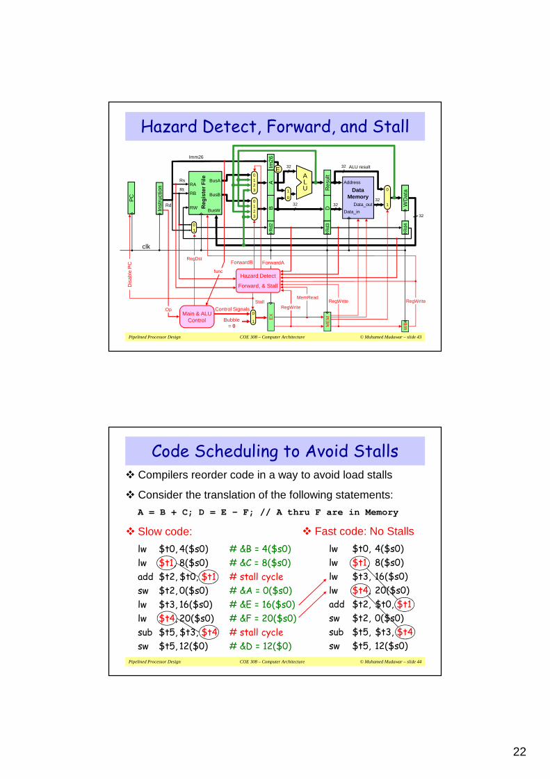
Pipelined Processor Design COE 308 – Computer Architecture © Muhamed Mudawar – slide 43
Control Signals
Bubble= 0
0
1
Hazard Detect, Forward, and Stall
0123
0123
Res
ult
3232
clk
Rd
32
Rs
01
ALU result
32
0
1
DataMemory
Address
Data_in
Data_out
32
Rd4
ALU
E
Imm26
1
0
Rd3
Rd2
AB W
Dat
a
D
Im26
32
Reg
iste
r F
ile
RB
BusA
BusB
RW BusW
RARt
Inst
ruct
ion
ForwardB ForwardA
Hazard Detect
Forward, & Stall
func
RegDst
Main & ALUControl
Op
ME
MEX
WB
RegWriteRegWriteRegWrite
MemReadStall
Dis
able
PC
P
C
Pipelined Processor Design COE 308 – Computer Architecture © Muhamed Mudawar – slide 44
Code Scheduling to Avoid Stalls� Compilers reorder code in a way to avoid load stalls
� Consider the translation of the following statements:
A = B + C; D = E – F; // A thru F are in Memory
� Slow code:
lw $t0, 4($s0) # &B = 4($s0)
lw $t1, 8($s0) # &C = 8($s0)
add $t2, $t0, $t1 # stall cycle
sw $t2, 0($s0) # &A = 0($s0)
lw $t3, 16($s0) # &E = 16($s0)
lw $t4, 20($s0) # &F = 20($s0)
sub $t5, $t3, $t4 # stall cycle
sw $t5, 12($0) # &D = 12($0)
� Fast code: No Stalls
lw $t0, 4($s0)
lw $t1, 8($s0)
lw $t3, 16($s0)
lw $t4, 20($s0)
add $t2, $t0, $t1
sw $t2, 0($s0)
sub $t5, $t3, $t4
sw $t5, 12($s0)
23
Pipelined Processor Design COE 308 – Computer Architecture © Muhamed Mudawar – slide 45
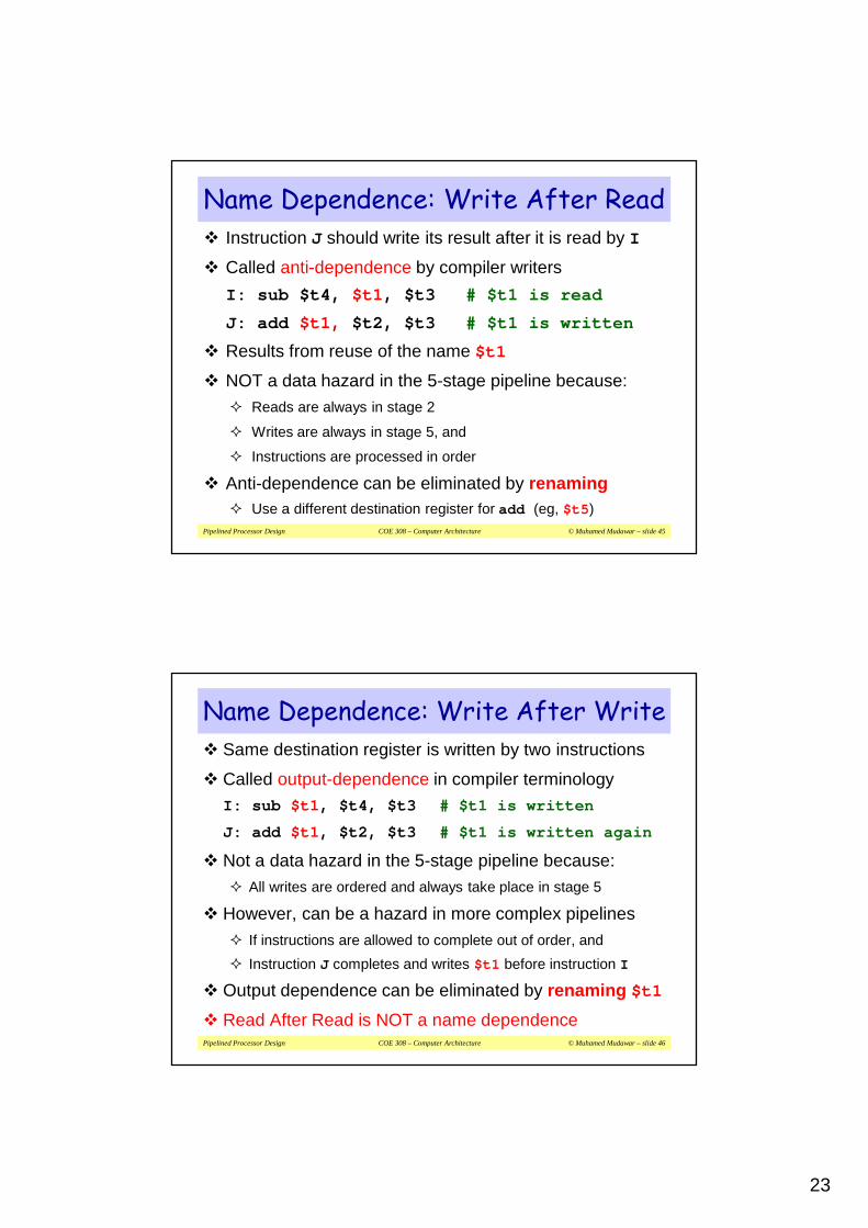
� Instruction J should write its result after it is read by I
� Called anti-dependence by compiler writers
I: sub $t4, $t1 , $t3 # $t1 is read
J: add $t1 , $t2, $t3 # $t1 is written
� Results from reuse of the name $t1
� NOT a data hazard in the 5-stage pipeline because:
� Reads are always in stage 2
� Writes are always in stage 5, and
� Instructions are processed in order
� Anti-dependence can be eliminated by renaming� Use a different destination register for add (eg, $t5 )
Name Dependence: Write After Read
Pipelined Processor Design COE 308 – Computer Architecture © Muhamed Mudawar – slide 46
Name Dependence: Write After Write� Same destination register is written by two instructions
� Called output-dependence in compiler terminology
I: sub $t1 , $t4, $t3 # $t1 is written
J: add $t1 , $t2, $t3 # $t1 is written again
� Not a data hazard in the 5-stage pipeline because:
� All writes are ordered and always take place in stage 5
� However, can be a hazard in more complex pipelines
� If instructions are allowed to complete out of order, and
� Instruction J completes and writes $t1 before instruction I
� Output dependence can be eliminated by renaming $t1
� Read After Read is NOT a name dependence

24
Pipelined Processor Design COE 308 – Computer Architecture © Muhamed Mudawar – slide 47
Next . . .
� Pipelining versus Serial Execution
� Pipelined Datapath and Control
� Pipeline Hazards
� Data Hazards and Forwarding
� Load Delay, Hazard Detection, and Stall
� Control Hazards
� Delayed Branch and Dynamic Branch Prediction
Pipelined Processor Design COE 308 – Computer Architecture © Muhamed Mudawar – slide 48
Control Hazards� Jump and Branch can cause great performance loss
� Jump instruction needs only the jump target address
� Branch instruction needs two things:
� Branch Result Taken or Not Taken
� Branch Target Address
� PC + 4 If Branch is NOT taken
� PC + 4 + 4 × immediate If Branch is Taken
� Jump and Branch targets are computed in the ID stage
� At which point a new instruction is already being fetched
� Jump Instruction: 1-cycle delay
� Branch: 2-cycle delay for branch result (taken or not taken)

25
Pipelined Processor Design COE 308 – Computer Architecture © Muhamed Mudawar – slide 49
2-Cycle Branch Delay� Control logic detects a Branch instruction in the 2nd Stage
� ALU computes the Branch outcome in the 3rd Stage
� Next1 and Next2 instructions will be fetched anyway
� Convert Next1 and Next2 into bubbles if branch is taken
Beq $t1,$t2,L1 IF
cc1
Next1
cc2
Reg
IF
Next2
cc4 cc5 cc6 cc7
IF Reg DMALU
BubbleBubble Bubble
BubbleBubble BubbleBubble
L1: target instruction
cc3
BranchTargetAddr
ALU
Reg
IF
Pipelined Processor Design COE 308 – Computer Architecture © Muhamed Mudawar – slide 50
Implementing Jump and Branch
zero
clk
32
ALU
325
Address
Instruction
InstructionMemory Rs
5Rt1
0
32
Reg
iste
r F
ile
RA
RB
BusA
BusB
RWBusW
E
PC
ALU
out
D
Imm16
Imm26
AB
Im26
NP
C2
Inst
ruct
ion
NP
C
+1
0
1Rd
Rd20
1 Rd3
PCSrc
Bne
Beq
J
Op
RegDst
EX
J, Beq, Bne
ME
M
Main & ALUControl
func
Next PC
0
2
3
1
0
2
3
1
Control Signals0
1Bubble = 0
Branch Delay = 2 cycles
Branch target & outcome are computed in ALU stage
Jum
p or
Bra
nch
Targ
et

26
Pipelined Processor Design COE 308 – Computer Architecture © Muhamed Mudawar – slide 51
Predict Branch NOT Taken
� Branches can be predicted to be NOT taken
� If branch outcome is NOT taken then
� Next1 and Next2 instructions can be executed
� Do not convert Next1 & Next2 into bubbles
� No wasted cycles
Beq $t1,$t2,L1 IF
cc1
Next1
cc2
Reg
IF
Next2
cc3
NOT TakenALU
Reg
IF Reg
cc4 cc5 cc6 cc7
ALU DM
ALU DM
Reg
Reg
Pipelined Processor Design COE 308 – Computer Architecture © Muhamed Mudawar – slide 52
Reducing the Delay of Branches
� Branch delay can be reduced from 2 cycles to just 1 cycle
� Branches can be determined earlier in the Decode stage
� A comparator is used in the decode stage to determine branch decision, whether the branch is taken or not
� Because of forwarding the delay in the second stage will be increased and this will also increase the clock cycle
� Only one instruction that follows the branch is fetched
� If the branch is taken then only one instruction is flushed
� We should insert a bubble after jump or taken branch
� This will convert the next instruction into a NOP
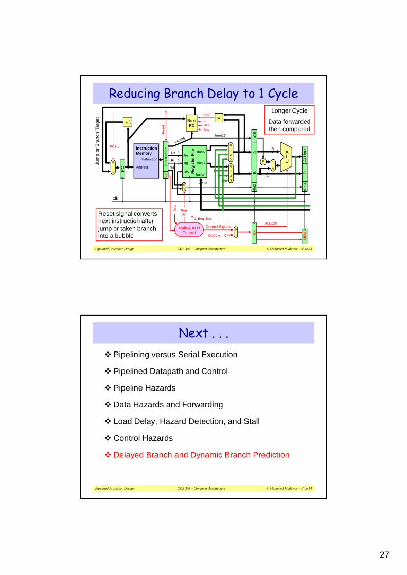
27
Pipelined Processor Design COE 308 – Computer Architecture © Muhamed Mudawar – slide 53
J, Beq, Bne
Reducing Branch Delay to 1 Cycle
clk
32
ALU
325
Address
Instruction
InstructionMemory Rs
5Rt1
0
32
Reg
iste
r F
ile
RA
RB
BusA
BusB
RWBusW
E
PC
ALU
out
D
Imm16
AB
Im16
Inst
ruct
ion
+1
0
1Rd
Rd20
1 Rd3
PCSrc
BneBeqJ
Op
RegDst
EX
ME
M
Main & ALUControl
func
0
2
3
1
0
2
3
1
Control Signals0
1Bubble = 0
Jum
p or
Bra
nch
Targ
et
Reset signal converts next instruction after jump or taken branch into a bubble
Zero=
ALUCtrl
Res
et
Next PC
Longer Cycle
Data forwarded then compared
Pipelined Processor Design COE 308 – Computer Architecture © Muhamed Mudawar – slide 54
Next . . .
� Pipelining versus Serial Execution
� Pipelined Datapath and Control
� Pipeline Hazards
� Data Hazards and Forwarding
� Load Delay, Hazard Detection, and Stall
� Control Hazards
� Delayed Branch and Dynamic Branch Prediction

28
Pipelined Processor Design COE 308 – Computer Architecture © Muhamed Mudawar – slide 55
Branch Hazard Alternatives� Predict Branch Not Taken (previously discussed)
� Successor instruction is already fetched
� Do NOT Flush instruction after branch if branch is NOT taken
� Flush only instructions appearing after Jump or taken branch
� Delayed Branch
� Define branch to take place AFTER the next instruction
� Compiler/assembler fills the branch delay slot (for 1 delay cycle)
� Dynamic Branch Prediction
� Loop branches are taken most of time
� Must reduce branch delay to 0, but how?
� How to predict branch behavior at runtime?
Pipelined Processor Design COE 308 – Computer Architecture © Muhamed Mudawar – slide 56
� Define branch to take place after the next instruction
� For a 1-cycle branch delay, we have one delay slot
branch instruction
branch delay slot (next instruction)
branch target (if branch taken)
� Compiler fills the branch delay slot
� By selecting an independent instruction
� From before the branch
� If no independent instruction is found
� Compiler fills delay slot with a NO-OP
Delayed Branch
label:
. . .
add $t2,$t3,$t4
beq $s1,$s0,label
Delay Slot
label:
. . .
beq $s1,$s0,label
add $t2,$t3,$t4

29
Pipelined Processor Design COE 308 – Computer Architecture © Muhamed Mudawar – slide 57
� New meaning for branch instruction
� Branching takes place after next instruction (Not immediately!)
� Impacts software and compiler
� Compiler is responsible to fill the branch delay slot
� For a 1-cycle branch delay � One branch delay slot
� However, modern processors and deeply pipelined
� Branch penalty is multiple cycles in deeper pipelines
� Multiple delay slots are difficult to fill with useful instructions
� MIPS used delayed branching in earlier pipelines
� However, delayed branching is not useful in recent processors
Drawback of Delayed Branching
Pipelined Processor Design COE 308 – Computer Architecture © Muhamed Mudawar – slide 58
Zero-Delayed Branching� How to achieve zero delay for a jump or a taken branch?
� Jump or branch target address is computed in the ID stage
� Next instruction has already been fetched in the IF stage
Solution
� Introduce a Branch Target Buffer (BTB) in the IF stage
� Store the target address of recent branch and jump instructions
� Use the lower bits of the PC to index the BTB
� Each BTB entry stores Branch/Jump address & Target Address
� Check the PC to see if the instruction being fetched is a branch
� Update the PC using the target address stored in the BTB

30
Pipelined Processor Design COE 308 – Computer Architecture © Muhamed Mudawar – slide 59
Branch Target Buffer� The branch target buffer is implemented as a small cache
� Stores the target address of recent branches and jumps
� We must also have prediction bits� To predict whether branches are taken or not taken
� The prediction bits are dynamically determined by the hardware
mux
PC
Branch Target & Prediction Buffer
Addresses of
Recent Branches
Target
Addresses
low-order bits used as index
Predict
BitsInc
=predict_taken
Pipelined Processor Design COE 308 – Computer Architecture © Muhamed Mudawar – slide 60
Dynamic Branch Prediction� Prediction of branches at runtime using prediction bits
� Prediction bits are associated with each entry in the BTB� Prediction bits reflect the recent history of a branch instruction
� Typically few prediction bits (1 or 2) are used per entry
� We don’t know if the prediction is correct or not
� If correct prediction …� Continue normal execution – no wasted cycles
� If incorrect prediction (misprediction) …� Flush the instructions that were incorrectly fetched – wasted cycles
� Update prediction bits and target address for future use

31
Pipelined Processor Design COE 308 – Computer Architecture © Muhamed Mudawar – slide 61
Correct PredictionNo stall cycles
YesNo
Dynamic Branch Prediction – Cont’dUse PC to address Instruction
Memory and Branch Target Buffer
FoundBTB entry with predict
taken?
Increment PC PC = target address
Mispredicted Jump/branchEnter jump/branch address, target
address, and set prediction in BTB entry.Flush fetched instructions
Restart PC at target address
Mispredicted branchBranch not taken
Update prediction bitsFlush fetched instructionsRestart PC after branch
NormalExecution
YesNo
Jumpor takenbranch?
Jumpor takenbranch?
No Yes
IFID
EX
Pipelined Processor Design COE 308 – Computer Architecture © Muhamed Mudawar – slide 62
� Prediction is just a hint that is assumed to be correct
� If incorrect then fetched instructions are flushed
� 1-bit prediction scheme is simplest to implement
� 1 bit per branch instruction (associated with BTB entry)
� Record last outcome of a branch instruction (Taken/Not taken)
� Use last outcome to predict future behavior of a branch
1-bit Prediction Scheme
Predict Not Taken
Taken
Predict Taken
NotTaken
Not Taken
Taken

32
Pipelined Processor Design COE 308 – Computer Architecture © Muhamed Mudawar – slide 63
1-Bit Predictor: Shortcoming
� Inner loop branch mispredicted twice!
� Mispredict as taken on last iteration of inner loop
� Then mispredict as not taken on first iteration of inner loop next time around
outer: …
…
inner: …
…
bne …, …, inner
…
bne …, …, outer
Pipelined Processor Design COE 308 – Computer Architecture © Muhamed Mudawar – slide 64
� 1-bit prediction scheme has a performance shortcoming
� 2-bit prediction scheme works better and is often used
� 4 states: strong and weak predict taken / predict not taken
� Implemented as a saturating counter
� Counter is incremented to max=3 when branch outcome is taken
� Counter is decremented to min=0 when branch is not taken
2-bit Prediction Scheme
Not Taken
Taken
Not Taken
TakenStrongPredict
Not Taken
Taken
WeakPredict Taken
Not Taken
WeakPredict
Not TakenNot Taken
TakenStrongPredict Taken

33
Pipelined Processor Design COE 308 – Computer Architecture © Muhamed Mudawar – slide 65
Fallacies and Pitfalls�Pipelining is easy!
� The basic idea is easy
� The devil is in the details� Detecting data hazards and stalling pipeline
�Poor ISA design can make pipelining harder
� Complex instruction sets (Intel IA-32)� Significant overhead to make pipelining work
� IA-32 micro-op approach
� Complex addressing modes� Register update side effects, memory indirection
Pipelined Processor Design COE 308 – Computer Architecture © Muhamed Mudawar – slide 66
Pipeline Hazards Summary� Three types of pipeline hazards
� Structural hazards: conflicts using a resource during same cycle
� Data hazards: due to data dependencies between instructions
� Control hazards: due to branch and jump instructions
� Hazards limit the performance and complicate the design
� Structural hazards: eliminated by careful design or more hardware
� Data hazards are eliminated by forwarding
� However, load delay cannot be eliminated and stalls the pipeline
� Delayed branching can be a solution when branch delay = 1 cycle
� BTB with branch prediction can reduce branch delay to zero
� Branch misprediction should flush the wrongly fetched instructions