PIPE AND ROOF DEICING KIT BAG - Heat tracing - Freeze...
16
Transcript of PIPE AND ROOF DEICING KIT BAG - Heat tracing - Freeze...

Heater CableGT-60
Fiberglass TapeWaterproofed
Insulation
GRK-E-1 End Seal
Standard Plug
In-Line Ground Fault Circuit Interrupter
(Optional) See note 4
GRK-S-1 Splice
GENERAL INFORMATION
1) Heating cables must be installed in compliance with all national, state, provincial and local electrIcal codes. Check with your local inspector for specific details.
2) These instructions must be retained and made available to the user and transferred to future users.3) Heating cables must not be energized in summer conditions.4) It is mandatory, by the electrical code, that the circuit supplying the heating cable have ground fault protection.
Consult an electrical inspector to determine the specific ground fault requirements for your application prior to installation.
5) Remove any old heating cable or insulation before installing the new cable.6) Do not bend the cable to less than 5 times its diameter.7) For further installation and testing instructions for the heating cable, please refer to the current edition of our
manual HT-213.
PIPE AND ROOF DEICING KIT BAGPIPE AND ROOF DEICING KIT BAGPIPE AND ROOF DEICING KIT BAGPIPE AND ROOF DEICING KIT BAG
PRECAUTIONS
METAL ROOFSHINGLE ROOF FLAT ROOF
The PRKB kit includes components to produce 1 cable set for pipe freeze protection and/or preventing the formation of ice dams on roofs and gutters. The CCA and FPS families of heating cables are suitable for:• use on metal or plastic pipes but not on flexible vinyl tubing• use in metallic and non-metallic gutters and downspouts• use on shingle slate, metal, wood or flat roofs.The self-regulating heating cables are designed to change their heat output with the surrounding temperature. As the temperature increases, the output of the cable decreases and vice versa. A pilot light in the plug indicates when power is applied to the cable.
2

1 GRK-S-1 Splice kit: to splice the power cord to the heat tracing cable (with installation instructions) for the heat tracing cable (with installation instructions)1 GRK-E-1 End seal kit:
in one of the following versions:1 POWER CORD
1 LABEL to be affixed to the power cord within 75 mm (3'') of the plug and filled out as follows:
Date of installation: Year / Month / DayThe heat tracing cable part number printed on the cable:CCA Family: 3CCA-1BA FPS Family: 3FPS-1BT 6CCA-1BA 5FPS-1BT 8CCA-1BA 8FPS-1BT 10FPS-1BT
To get the total watts, multiply the watts/ft (m) for the specific application as listed below by the length in feet or meters of the heat tracing cable.
3CCA-1BA6CCA-1BA8CCA-1BA
3FPS-1BT5FPS-1BT8FPS-1BT
10FPS-1BT
Walts/ft (m) per application
KIT CONTENTS
mA trip rating 6, 10, 19, 27 or otherBlank: with Standard Plug
PGF - On-Plug Ground Fault circuit interrupterIGF - In-line Ground Fault circuit interrupter with Standard Plug
SP - Standard Plug w/o Ground Fault Interrupter (to be plugged into a GFI protected wall outlet)
PRKB- XX-XX
Date:Cat. No.:
Watts:
Cable type
METAL PIPE PLASTIC PIPE ROOF & GUTTERS
3W/ft(10W/m)6W/ft (20W/m)8W/ft (26W/m)
3W/ft (10W/m) 5W/ft (16W/m)8W/ft (26W/m)
10W/ft (33W/m)
1.8W/ft (6W/m)4.5W/ft (15W/m)
6W/ft (20W/m)
2W/ft (6.5W/m)3.8W/ft (12W/m) 5.8W/ft (19W/m) 6.8W/ft (22W/m)
N/A10W/ft (33W/m)13W/ft (43W/m)
N/A
9 W/ft (29W/m) 13 W/ft (43W/m)
N/A
3
1. Refer to installation instructions (GRK-S & GRK-E) and appropriate brochures. Se référer aux instructions d’installation (GRK-S & GRK-E) et aux brochures appropriées.
2. Set Designation: 2E, 3A, 3C, designation de l’ensemble
SERGE BARIL & ASS.INC.5310 des Laurentides, Laval, QC, CANADA H7K 2J8
PIPE/ROOF APPLICATIONS TUYAU ET TOITURE
For use with parallel heating cables / a être utilisées avec les câbles chauffants de type parallèle
Date
Affix this Label to within 75 mm (3") of the Power Connection
Apposer cette étiquette à 75 mm (3") de la connexion
HT-450-121130
Cat. No. Watts Volts
120

ON PIPE FREEZE PROTECTION HEATING ON PIPE FREEZE PROTECTION HEATING CABLE CORD SETSCABLE CORD SETSON PIPE FREEZE PROTECTION HEATING ON PIPE FREEZE PROTECTION HEATING CABLE CORD SETSCABLE CORD SETS
Heater CableGT-60
Fiberglass TapeWaterproofed
Insulation
GRK-E-1 End Seal
Standard Plug
In-Line Ground Fault Circuit Interrupter
(Optional) See note 4 on page 2
GRK-S-1 Splice
THE INFORMATION BELOW APPLIES TO BOTH CCA & FPS FAMILIES OF HEATERS
Water supply pipe either not deep enough in the ground or installed on the surface, both leading to a potential pipe freeze-up.
Installing the CCA family of heating cable on the outside of the pipe and covering it with adequate insulation. The pipe must be insulated with fibreglass or equivalent
insulation. The insulation must be covered with a waterproof jacket. Remember, wet insulation is conductive and worse than no insulation.
The parallel bus wires apply voltage along the entire length of the heater cable. The conductive core provides an infinite number of parallel conductive paths permitting the cable to be cut to any length in the field with no dead or cold zones developing. The heater cable derives its self-regulating characteristic from the inherent properties of the conductive core material. As the core material temperature increases, the number of conductive paths in the core material decreases, automatically decreasing the heat output. As the
temperature decreases, the number of conductive paths increases, causing the heat output to increase. This occurs at every point along the length of the cable, adjusting the power output to the varying conditions along the pipe. The self-regulating effect prevents damage to even an empty pipe. As the cable self-regulates its heat output, it provides for the efficient use of electric power, producing more heat when and where it is needed, and also limiting the maximum sheath temperature of the cable.
0 0De-energized 185 F (85 C)
0 0Energized 150 F (65 C)
THE PROBLEM:
THE SOLUTION:
OTHER TYPICAL APPLICATIONS:OTHER TYPICAL APPLICATIONS:OTHER TYPICAL APPLICATIONS:
PRINCIPLE OF OPERATION:PRINCIPLE OF OPERATION:PRINCIPLE OF OPERATION:
MAXIMUM EXPOSURE TEMPERATURE:MAXIMUM EXPOSURE TEMPERATURE:MAXIMUM EXPOSURE TEMPERATURE:
Pipe & tank freeze protectionMaintain temperature in product pipelinesSprinkler freeze protection
Hot water systems Drains, roofs & guttersComfort and space heating
NOTE: Please consult SBA for the appropriate publication for your application.
0 0Exposure to temperature above 150 F (65 C) will shorten the life of your cable. 0 0Before installing on hot water pipes, set the water heater thermostat below 150 F (65 C).
COMPONENTS:GT-60 Fibreglass tape 60ft (18m), with requirements established as follows:
AT-150 Aluminum tape, 2in x 150ft (50mm x 45m) for plastic pipes.ETL-E Electric trace label - one label every 10ft (3m) is recommended.
GT-180 Fibreglass tape 180ft (55m).
Pipe size in inches/mm
Ft (m) of pipe per roll of GT
< 2 (50) 10 (250)
60 (20)
3 (75)
50 (15)
4 (100)
40 (12)
6 (150)
25 (7)
8 (200)
20 (6) 15 (5)
4

The following information is required in order to determine the length and type of cable required:
Diameter of the pipeLength of the pipeMinimum ambient temperatureNumber, type, and length of valves, if applicableThickness of insulation based on fibreglass (for other types, consult your Serge Baril representative)Number of flanges and uninsulated supports, if applicable
Note: This design is for water pipes only and using fibreglass insulation. For process temperature maintenance or for use of other insulation materials consult our design guide (HT-201) for heat tracing of pipes and vessels.
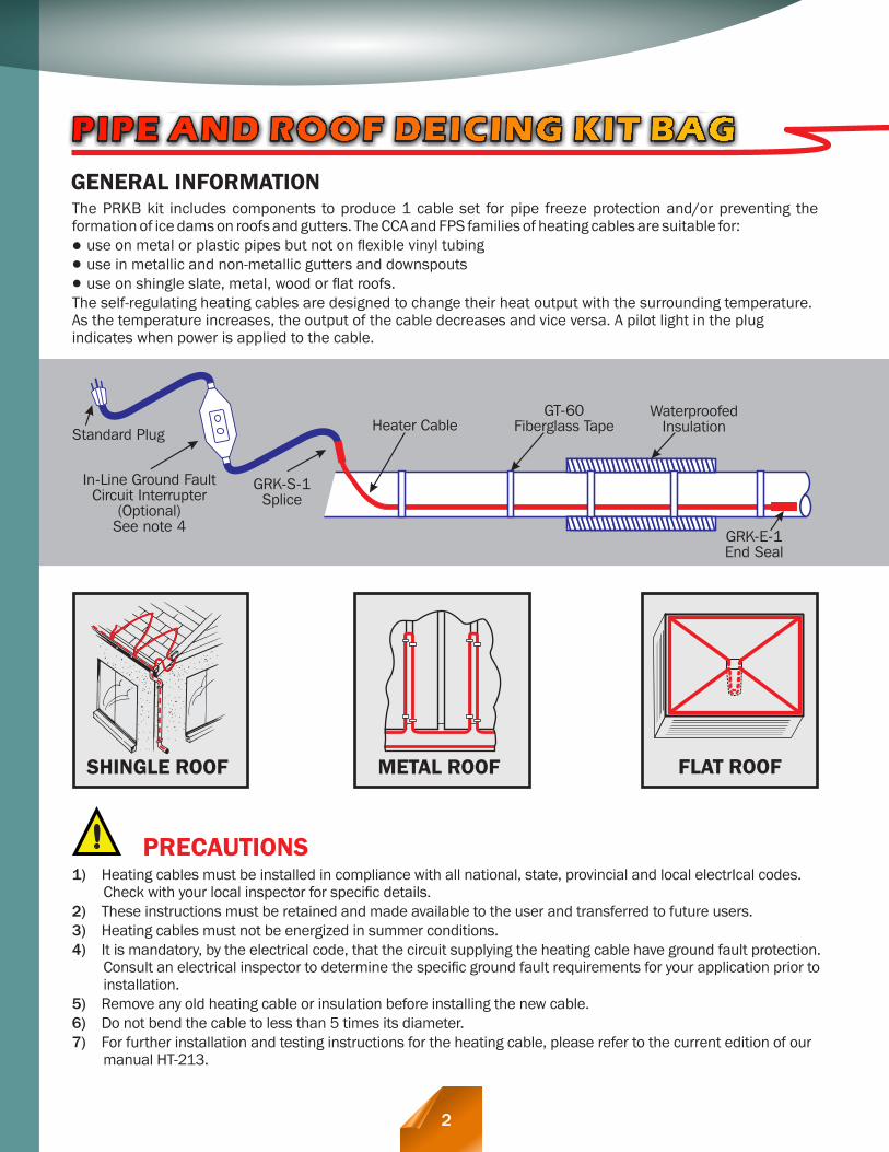
Table1 0 0 provides the CCA heater cable selection to maintain 40 F(5 C) on a metal or plastic pipe with the use of fiberglass or equivalent insulation. It shows three types of installation and should be read as follows:
STEP 1 DESIGN INFORMATION
STEP 2 CHOICE OF CCA HEATER
For the choice of CCA heater per pipe diameter and insulation thickness refer to TABLE 1, COLUMN I. For the length of heater required, see the formula at STEP-3. The cable uses components as listed on page 4 and is attached at 1 ft (300 mm) intervals with fiberglass tape (GT- 60). It is positioned as shown in FIGURE 1.
CAUTION: Certain plastic pipe materials have low maximum allowable temperatures. Contact your local Serge Baril representative to verify if the use of an uncontrolled (no thermostat) heater application is appropriate or recommended given the specific pipe material and the rated maximum temperature.
THERE ARE TWO CHOICES OF INSTALLATION FOR A PLASTIC PIPE:
For the choice of CCA heater per pipe diameter and insulation thickness refer to TABLE 1, COLUMN II. For the length of heater required, see the formula at STEP-3.
The cable uses components as listed on page 4 and is attached at 1 ft (300mm) intervals with fiberglass tape (GT-60). It is positioned, as shown in FIGURE 1.
1. HEATER CABLE INSTALLED DIRECTLY ON THE PLASTIC PIPE
2. HEATER CABLE INSTALLED ON PLASTIC PIPE AND COVERED LENGTHWISE WITH ALUMINUM TAPE
The use of aluminum tape (AT-150) installed lengthwise on the heater helps dissipate the heat thus requiring fewer watts per foot. For the choice of CCA heater per pipe diameter and insulation thickness refer to TABLE 1,
COLUMN III. For the length of heater required, refer to the formula at STEP-3. The cable uses components as listed on page 4. It is positioned, as shown in FIGURE 1.
METAL PIPES:
PLASTIC PIPES:0120
ALTERNATE LOCATIONS
Figure 1
5
Heater Cable
Fiberglass Tape
INSTALLATION ON VALVE
For a complete installation guide, please refer to: Serge Baril Heat Tracing Systems Installation and maintenance - Self Regulating Heater Cable (HT213).
Self-regulatingTypical installation method.
(May vary for different valve shapes)
TYPICAL INSTALLATION TIPS

A D V A N T A G E S :Very flexible, therefore easier to install.Can be used with or without thermostat.Can be installed on all types of water lines.
Cut to length for the project.Reduced electrical costs.Adjusts its power output whereand when it is required.
STEP 3 LENGTH FORMULATOTAL LENGTH OF HEATER REQUIRED = Pipe length (in ft or m) + 1 foot (0.3m) for the connectionadd if applicable + 4x number of gate valves x length of valve in ft or m + 2x number of ball or butterfly valves x length of valve in ft or m + 2x number of flanges x diameter of pipe in ft or m + extra length for pipe supports
6
Bar Hanger
Heater CableBar HangerFiberglass Tape
Do not clamp heater Cable under hanger bracket
Hanger support
Elbow
Heater Cable
Fiberglass Tape
Heater Cable should be positioned on the outside radius of all elbows on 50 mm (2'') dia. pipes & larger.
Heater CablePipe Shoe Support
Fiberglass Tape
Heater CablePipe Shoe Support
Fiberglass Tape
Shoe support
Heater CableFiberglass Tape
Flange
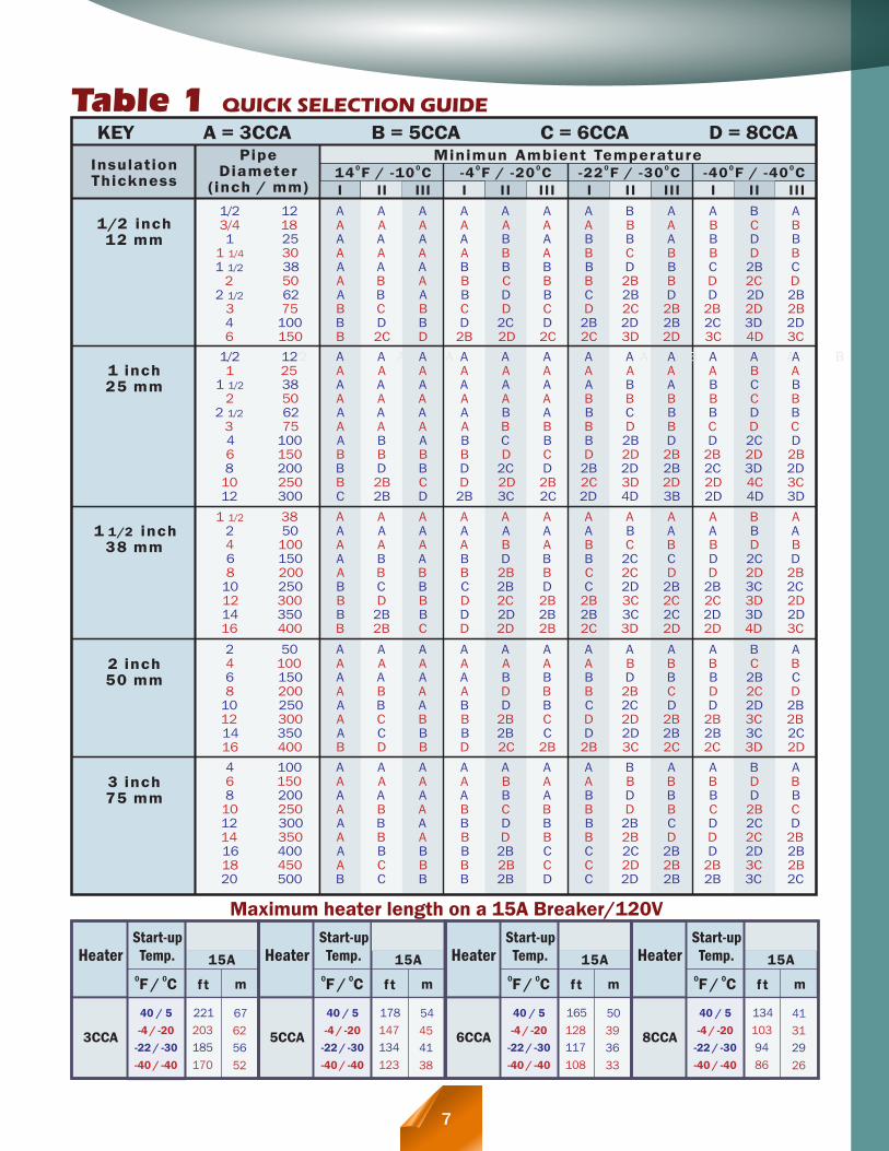
Table 1 QUICK SELECTION GUIDE
Minimun Ambient Temperature0 0
14 F / -10 C0 0
-4 F / -20 C0 0
-22 F / -30 C0 0
-40 F / -40 C
KEY A = 3CCA B = 5CCA C = 6CCA D = 8CCA
I II III I I I I I I I I I I I I I I I I I I
Pipe Diameter
(inch / mm)
Insulation Thickness
1/2 inch 12 mm
1 inch 25 mm
1 1/2 inch 38 mm
3 inch 75 mm
2 inch 50 mm
12 1/2 A A A A A A A B A A B A1/2 12 A A A A A A A A A A A A1 25 A A A A A A A A A A B A
1 1/2 38 A A A A A A A B A B BC2 50 A A A A A A B B B B C B
2 1/2 62 A A A A B A B C B B D B3 75 A A A A B B B D B C D C4 100 A B A B C B B 2B D D 2C D6 150 B B B B D C D 2D 2B 2B 2D 2B8 200 B D B D 2C D 2B 2D 2B 2C 3D 2D10 250 B 2B C D 2D 2B 2C 3D 2D 2D 4C 3C12 300 C 2B D 2B 3C 2C 2D 4D 3B 2D 4D 3D
1/2 12 A A A A A A A B A A B A3/4 18 A A A A A A A B A B C B1 25 A A A A B A B B A B BD
1 1/4 30 A A A A B A B C B B D B1 1/2 38 A A A B B B B D B C 2B C
2 50 A B A B C B B 2B B D 2C D2 1/2 62 A B A B D B C 2B D D 2D 2B
3 75 B C B C D C D 2C 2B 2B 2D 2B4 100 B D B D 2C D 2B 2D 2B 2C 3D 2D6 150 B 2C D 2B 2D 2C 2C 3D 2D 3C 4D 3C
1 1/2 38 A A A A A A A A A A B A2 50 A A A A A A A B A A B A4 100 A A A A B A B C B B BD6 150 A B A B D B B 2C C D 2C D8 200 A B B B 2B B C 2C D D 2D 2B
10 250 B C B C 2B D C 2D 2B 2B 3C 2C12 300 B D B D 2C 2B 2B 3C 2C 2C 3D 2D14 350 B 2B B D 2D 2B 2B 3C 2C 2D 3D 2D16 400 B 2B C D 2D 2B 2C 3D 2D 2D 4D 3C
2 50 A A A A A A A A A A B A4 100 A A A A A A A B B B C B6 150 A A A A B B B D B B C2B8 200 A B A A D B B 2B C D 2C D
10 250 A B A B D B C 2C D D 2D 2B12 300 A C B B 2B C D 2D 2B 2B 3C 2B14 350 A C B B 2B C D 2D 2B 2B 3C 2C16 400 B D B D 2C 2B 2B 3C 2C 2C 3D 2D
4 100 A A A A A A A B A A B A6 150 A A A A B A A B B B D B8 200 A A A A B A B D B B BD10 250 A B A B C B B D B C 2B C12 300 A B A B D B B 2B C D 2C D14 350 A B A B D B B 2B D D 2C 2B16 400 A B B B 2B C C 2C 2B D 2D 2B18 450 A C B B 2B C C 2D 2B 2B 3C 2B20 500 B C B B 2B D C 2D 2B 2B 3C 2C
HeaterStart-up
Temp. 15A0 0F / C f t m
3CCA
6722140 / 5
62203-4 / -20
56185-22 / -30
52170-40 / -40
HeaterStart-up
Temp. 15A0 0F / C f t m
5CCA
5417840 / 5
45147-4 / -20
41134-22 / -30
38123-40 / -40
HeaterStart-up
Temp. 15A0 0F / C f t m
6CCA
5016540 / 5
39128-4 / -20
36117-22 / -30
33108-40 / -40
HeaterStart-up
Temp. 15A0 0F / C f t m
8CCA
4113440 / 5
31103-4 / -20
2994-22 / -30
2686-40 / -40
Maximum heater length on a 15A Breaker/120V
7

ICE FORMATION ON THE EDGE ICE FORMATION ON THE EDGE OF THE ROOFOF THE ROOFICE FORMATION ON THE EDGE OF THE ROOFLeading toLeading toLeading to
WATER INGRESS IN THE HOUSEWATER INGRESS IN THE HOUSEWATER INGRESS IN THE HOUSE
EXPLANATION
THE SOLUTION: RELATIVELY EASY -
KEEP THE PATH OPEN!
In cold weather, heat from the house rises and eventually heats the attic area. Ceiling insulation, while needed to reduce heating requirements in the house, does not prevent but only delays this build-up of heat in the attic. Snow on the roof acts as a good insulator creating a temperature differential between the attic and the outside. The temperature of the attic increases compared to the outside temperature. This allows the underside of the snow on the roof to gradually melt and form water droplets. These will flow down the roof forming ice dams by freezing as they reach the unheated cold roof edge (over the eaves, outside the walls). These water droplets may eventually freeze in the gutters, climb over the ice-filled gutter and form major, dangerous icicles.
As this ice builds-up, it creates a bigger dam. The ice forms a barrier and melted water accumulates behind this ice dam and may leak inside the wall space, under the shingles and into the building, causing water damage.''The roof is leaking!'' ... not really, what has happened is the ice build-up stopped the flow of water down the roof and allowed it to leak into the house.
Serge Baril roof & gutter de-icing system offers the best way to help prevent ice dams and icicles using a self-regulating heating cable that provides a continuous drain path for melted ice and snow from the roof through the gutters and downspouts to the drain.
Ice DamHeat
Duct
Ponding
Snow
Icicles
Water Damage
Air Leakage by Convection
Heat Source
Snow
Ponding
Ice Dam
Icicles
Wet Insulation
Wet Insulation
Water Damage
JUST KEEP THE FLOW OF WATER DIRECTED OFF THE ROOF.
HEAT TRACING CORD SETS FORHEAT TRACING CORD SETS FORHEAT TRACING CORD SETS FORHEAT TRACING CORD SETS FOR
8
ROOF & GUTTER DEICING AND DRAINSROOF & GUTTER DEICING AND DRAINSROOF & GUTTER DEICING AND DRAINSROOF & GUTTER DEICING AND DRAINS
THE PROBLEM:
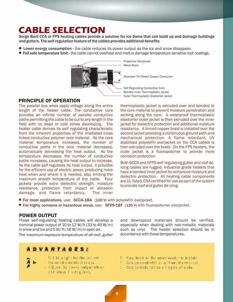
CABLE SELECTIONSerge Baril CCA or FPS heating cables provide a solution for ice dams that can build up and damage buildings and gutters. The self-regulation feature of the cables provides additional benefits:
Lower energy consumption - the cable reduces its power output as the ice and snow disappear. Fail safe temperature limit - the cable cannot overheat and melt or damage temperature sensitive roof coatings.
The parallel bus wires apply voltage along the entire length of the heater cable. The conductive core provides an infinite number of parallel conductive paths permitting the cable to be cut to any length in the field with no dead or cold zones developing. The heater cable derives its self regulating characteristic from the inherent properties of the irradiated cross linked conductive polymer core material. As the core material temperature increases, the number of conductive paths in the core material decreases, automatically decreasing the heat output. As the temperature decreases, the number of conductive paths increases, causing the heat output to increase. As the cable self-regulates its heat output, it provides for the efficient use of electric power, producing more heat when and where it is needed, also limiting the maximum sheath temperature of the cable. Four jackets provide extra dielectric strength, moisture resistance, protection from impact or abrasion damage, and flame retardancy. The inner
thermoplastic jacket is extruded over and bonded to the core material to prevent moisture penetration and wicking along the core. A waterproof thermoplastic elastomer outer jacket is then extruded over the inner jacket for dielectric protection and additional moisture resistance. A tinned copper braid is installed over the second jacket providing a continuous ground path and mechanical protection. A flame retardant, UV stabilized polyolefin overjacket on the CCA cables is then extruded over the braid. On the FPS heaters, the outer jacket is a fluoropolymer to provide more corrosion protection.
Both 6CCA and 5FPS self-regulating gutter and roof de-icing cables are rugged, industrial grade heaters that have a bonded inner jacket for enhanced moisture and dielectric protection. All heating cable components are UL listed, CSA certified for use as part of the system to provide roof and gutter de-icing.
PRINCIPLE OF OPERATION
These self-regulating heating cables will develop a nominal power output of 10 to 12 W/ft (33 to 40 W/m) in snow and ice and 5 W/ ft (16 W/m) in open air.
The maximum exposure temperature of all roof, gutter
and downspout materials should be verified, especially when dealing with non-metallic materials such as vinyl. The heater selection should be in accordance with these temperatures.
POWER OUTPUT
6CCA-1BA (120 V) with polyolefin overjacket. For highly corrosive or hazardous areas, use: For most applications, use:
5FPS-1BT (120 V) with fluoropolymer overjacket.
Protective Overjacket
Metal Braid
Stranded Tin Plated Copper Conductor
Self-Regulating Conductive Core
Bonded Inner Thermoplastic Jacket
Outer Thermoplastic Elastomer Jacket
A D V A N T A G E S :
Very flexible, therefore easier to install.Can be used with or without thermostat.Can be installed on all types of roofs.
Cut to length for the project.Reduced electrical costs.Adjusts its power output where and when it is required.
9

1. Before installing the cable, allow it to warm up to room temperature. Keep grommets and shrink tubes warm until used (keep inside of jacket pocket, etc.)
2. Clear all gutters and downspouts of debris (protect hands with gloves).
3. Remove any sharp edges that could damage the heater cable.
4. Mount the weatherproof junction box in a sheltered area. The junction box may be positioned to install the cables in different directions and thus reduce scrap.
5. Start the cable installation at the junction box, thus leaving a drip loop where the cable exits the junction
SERGE BARIL OFFERS THE SOLUTION FOR A WIDE SERGE BARIL OFFERS THE SOLUTION FOR A WIDE RANGE OF APPLICATIONS SUCH AS:RANGE OF APPLICATIONS SUCH AS:SERGE BARIL OFFERS THE SOLUTION FOR A WIDE RANGE OF APPLICATIONS SUCH AS:
SHINGLE ROOF
10
Caution: Both the National and Canadian Electrical Codes require the use of a ground fault protection device (GFPD) at all times in conjunction with the installation of all heat tracers.
FOR HIGHLY CORROSIVEHEATER LENGTH
Start temp. 0 0F / C
FT / M
5FPS-1BT 20 / -7
0 / -18
-20 / -29
-40 / -40
123 / 37
110 / 34
100 / 30
91 / 28
120 V
Maximum heater lengthCatalog NumberStart temp.
0 0F / CFT / m
6CCA-1BA 20 / -7
0 / -18
-20 / -29
-40 / -40
102 / 31
90 / 27
80 / 24
70 / 21
120 V
Maximum heater lengthCatalog Number
MAXIMUM HEATER LENGTH ON A 15A DEDICATED CIRCUIT
GENERAL NOTES:
STEP 1. HEATER ON ROOFInstall the 6CCA heater looped up and down 12'' (30 cm) beyond the eave overhang (see sketch) to the edge of the roof and to the bottom of the gutter to prevent ice build-up over the gutter. Cable spacing between the loops is normally 2 ft (60 cm). The amount of cable to be used will be affected by the depth of the eave overhang as shown in TABLE I below. This table provides the total number of feet or meters of cable required per foot or meter of roof edge.
The cable must be looped down over the edge of the roof and tied to the cable in the gutter using UV resistant cable ties. This is to help prevent the ice from bridging over the gutter.
12''
Eave Overhang
30 cm

If the cable is terminated at the bottom, the end should protrude some distance into the ground drainage under the frost line to prevent freezing or (see sketch 1)tied to the exterior of the downspout .(see sketch 2)
The downspouts which serve to lead the water to the ground or drain must also be heat traced. The cable is looped down and back, unless the downspout is on the end of circuit with the cable terminating at the bottom.
For the downspouts use a GRK-DH (downspout hanger), sold separately, to support the heating cable where it enters / exits a downspout. One hanger is required for each downspout.
STEP 3. DOWNSPOUT
11
The gutter requires a length of heater along the bottom to keep the flow of water to the drain. For gutters larger than 6'' (15 cm), multiple runs of heater cable are recommended. It is preferable to tie the cable
down with the use of aluminum tape (AT-150) in order to keep the cable flat and on the bottom of the gutter. This also helps dissipate the heat along the bottom of the gutter providing wider coverage.
1) Install the cable on the roof as shown above leaving loops protruding about 3'' (7.5 cm) over the edge of the roof.
2) A heat tracing cable can also be installed longitudinally under the drip lip of the roof. This could help prevent the built-up of ice and icicles along the edge of the roof.
This may well be adequate and could prove to be a good first step if there are no obvious ice dams forming on the roof. If this does not suffice, the roof can be heat traced following the above procedure at a later date.
STEP 2. HEATER IN GUTTER
NO GUTTERS?
TRACING GUTTERS ONLY?
TABLE I: CABLE LENGTH PER FT (M) OF ROOF EDGECable spacing is 2 ft (60 cm)
Eave Overhang
Feet (m) of cable/ Foot (m) of roof
24
36
48
60
60 3
90 4
120 5
150 6
Loop Height
12
24
36
48
30
60
90
120
inches cm inches cm
2 ft
2 ft
12''
30 cm
60 cm
60 cm

ROOF ATTACHMENTGRK-C roof clips can be used in conjunction with pipe strapping nailed directly into the shingles of a new roof (see sketch A). For existing structures, bend the top
edge of the pipe strapping before slipping it under the tile or shingle. Push up and pull back down to have the bent edge hook onto the top of the tile . (see sketch B)
Cable Clip(GRK-C)
Heater Cable
#8-32 Screw & Nut
Pipe StrappingPipe Strapping
Shingles
Overhang
Peg under Tile
Heater in the gutter
2 ft60 cm
12
Install the cable up to two thirds the height of the valley and back down.
Install the cable all around the perimeter of the dormer or skylight.
STEP 4. ROOF VALLEYS STEP 5. DORMERS OR SKYLIGHTS
TABLE II: TOTAL CABLE REQUIREMENTS: SLOPED SHINGLE ROOFTABLE II: TOTAL CABLE REQUIREMENTS: SLOPED SHINGLE ROOFTABLE II: TOTAL CABLE REQUIREMENTS: SLOPED SHINGLE ROOF
Roof _____________
X __________________ = _____________Roof length Cable multiplier
(from Table I)
Dormers _____________ X __________________ = _____________Quantity Perimeter
Valleys _____________ X __________________ = _____________Quantity 2/3 up and 2/3 down
Gutters _____________ X __________________ = _____________Length 1 pass / 6" (15 cm) width
Downspouts _____________ X __________________ = _____________Quantity Length x 2 (or 1 if end of circuit)
Connections _____________ X = _____________Quantity
2 ft (60 cm)
Cable length = _____________
Cable length x 5% = _____________
Total cable length = __________________________
STEP 6. CABLE LENGTH CALCULATION

Heater CableCable Clip
Gutter
Roof
Washer
Cable Clip(GRK-C)
Heater Cable (in bottom of gutter)
Heater Cable
Heater CableCable Clip
Gutter
Roof
Washer
Cable Clip(GRK-C)
Heater Cable (in bottom of gutter)
Heater Cable
Use GRK-C clips making sure to use self-sealing screws or other appropriate sealing mechanism to prevent water ingress. A typical rib cross-over is shown below.
ROOF ATTACHMENT
OR
Fasten with sheet metal screw using neoprene sealing washers. If washers are not available, coat the screw and the upslope edge of the clip with silicone sealant.
The exact cable spacing may vary depending on the rib design of the roof. Typically trace every other rib.
An alternative solution: A bead of adhesive (not furnished) should run along the pipe strapping for a length of 3'' (76 mm) prior to slipping the strapping up under the tile. Do not use an excessive amount so as to leave a visible blob of adhesive on the outer edge of the tile. The adhesive bead should be large enough to deform and smear along the surface of the tile underneath. Allow the adhesive to cure to full bonding strength before attempting to install the cable and clips.
GRK-C roof clips may have to be surface mounted as s h o w n . P l e a s e assure a complete s e a l b y u s i n g silicone or other appropriate sealing agent.
Heater Cable
Roof
Roofing Nail
Cable Clip (GRK-C) Silicone Sealant
13
SAVING: Because the loops at the edges of the roof have to be brought down to the bottom of the gutter, we can thus save the cable in the bottom of the gutter by attaching the loops together using UV protected Ty-raps and tie the cable down with the use of the aluminum tape (AT-150) in order to keep the cable flat in the bottom of the gutter. This also helps to dissipate the heat along the bottom of the gutter . (see sketch A)
FORMULA: (Eave overhang + 1 ½ ft (45 cm)) x number of ribs + length of roof.
2 ft2 ft2 ft
60 cm60 cm60 cm
The cable requirements for the loop on the roof are calculated as follows: the eave overhang plus 1½ ft (45 cm) which allows for extra cable to cover the portion of the roof inside the wall space plus the loop down to the gutter, multiplied by the number of ribs (2 traces on every second rib is equivalent to one trace per rib), plus the length of roof. See formula below.
Using the same logic as above, we basically have to guide a water droplet down the roof. The droplet should therefore meet a cable as it comes down. As such, we have to trace each second rib as shown on the drawing but not more than 2 ft (60 cm) between traces.
CABLE REQUIREMENTS ON ROOF
METAL ROOF
NOTES:1) Every second rib is to be traced but not beyond a
spacing of 2 ft (60 cm).
2) All the rest of applications such as dormers, gutters, downspouts are as per requirements for a shingle roof above.
Other cable requirements are as per TABLE II

Heater Cable
Drip LoopGutter Detail
Heater Cable
Aluminum Tape (AT-150) (optional)
GFI receptacle
for the Standard Plug
or appropriate outside
receptacle for a
GFI Plug
Downspout Hanger Detail
Hanger Wire
Nail or other support
ClampsProtective Tubing
Heater Cable
(GRK-DH)
Cable Clip (GRK-C)
End of CircuitDownspout Installation
End Seal (should not be submerged norbe allowed to be at the bottom
end of the downspout). If above ground, exceed end of downspout and tie it to the outside; ifunderground, make sure
that the end is below the frost level.
ROOF ATTACHMENTHeater Cable
Cable Clip (GRK-C)
Hardware Cloth .25'' (6.34 mm) max. Grid
#8 x 1/2'' (13 mm) Long Pan Head Screw
#8 Hex Nut
Use fibreglass or other appropriate sheet material to glue to the roof while having the GRK-C clips attached underneath this sheet as shown.
Adhesive (not furnished) should be used to bond the studs to the flat surface. The roof surface should be clean at the bonding locations. Do not penetrate flat roofs with screws or nails as leaks may develop. Allow the adhesive to cure to full bonding strength before attempting to install the cable and clips.
Scupper
Drip Loop
Jonction Box
Drain
SlopeThe principle is to keep a pathway open for the flow of water to the drain. There is generally a slope towards a central drain or towards an edge. Run the heat tracing cables from all corners to the drain making sure that the loops are bent into the drain. It is good practice to have one cable go down into the drain to prevent freezing. Lay heat tracers all along the perimeter.
FLAT ROOF
14

Once the installation is complete, apply power to the heating cable. Wait about one hour, and then turn on a water tap supplied by the protected pipe and test the temperature of the water. It should feel warm almost immediately as the water heated by the cable flows through the pipe.
TESTING THE SYSTEM
Energise the cable/control upon the arrival of cold weather in the fall and de-energize the cable in spring. Ensure power is removed from the heating cable in summer.
FOR PIPE INSTALLATION
Once the installation is complete, apply power to the heating cable. The surface of the cable will feel warm after 15 minutes.
FOR ROOF INSTALLATION
OPERATION
Check the cable annually for damage, such as nicks or cuts possibly caused by animals or other activity before energizing the heating cable. Check any ground fault protection devices for proper operation.
MAINTENANCE
15
Serge Baril offers an extension of our regular 1 year warranty on all self-regulating heating cables for a period of up to 10 years from the date of manufacture.
This extended warranty includes all terms, conditions and limitations of the basic warranty with the following additions:
Heating Cable Extended Warranty Acceptance form has been signed and returned to Serge Baril for registration.Heating cable failure is defined as having a 20% loss in power output.Warranty is void if product is installed on or with materials containing plasticizers, such as commonly used in vinyl tapes or vinyl insulations. The cables must have been installed according to the manufacturer's installation instructions by an approved installer.
1.
2.3.
SCOPE:
TEN YEAR EXTENDED WARRANTYTEN YEAR EXTENDED WARRANTYTEN YEAR EXTENDED WARRANTYTEN YEAR EXTENDED WARRANTYSELF REGULATING HEATER CABLESELF REGULATING HEATER CABLESELF REGULATING HEATER CABLESELF REGULATING HEATER CABLE
PROCEDURE:In the event of a claim, a ''claim information sheet'' must be completed and returned with all cable that has been removed.Serge Baril will provide replacement cable at normal price levels for the initial replacement.Upon examination of the returned cable and the determination that the cable is defective, Serge Baril will issue a credit for the defective cable.
1.
2.3.
Simply put one length of cable into the full length of the drain to be freeze protected.
DRAINS

GENERAL NOTE:
APPROVALS:
The above are general suggestions for applications of our cables and are not meant to replace the normal requirements of local, construction, electrical, or other codes. The installer must verify the conformity to all applicable codes or standards. We are pleased to offer suggestions on the use of our various products, nevertheless, there are no warranties given except such expressed warranties offered in connection with the sale of a particular product. There are no implied warranties of merchantability or of fitness for a particular purpose given in connection with the sale of any goods. In no event shall Serge Baril be liable for consequential, incidental or special damages. The buyer's sole and exclusive remedy and the limit of Serge Baril's liability for any loss whatsoever shall not exceed the original purchase price paid to SBA for the product or products for which a claim is made.
SERGE BARIL HEAT TRACING5310 des Laurentides Blvd., Laval, QC Canada H7K 2J8 HT-225-141115
Tel: (450) 622-7587
Fax: (450) 622-7869www. baril.ca
AVAILABLE AT:
OUR WORLD IS ELECTRICAL OUR WORLD IS ELECTRICAL HEAT TRACINGHEAT TRACING
OUR WORLD IS ELECTRICAL HEAT TRACING