PINBALL 2000 SCHEMATIC MANUAL
30
16-10882 February 1999 PINBALL 2000 SCHEMATIC MANUAL INCLUDING CABINET AND BACKBOX PARTS Williams Electronics Games, Inc. 3401 North California Avenue Chicago, IL 60618
Transcript of PINBALL 2000 SCHEMATIC MANUAL

16-10882February 1999
PINBALL 2000 SCHEMATIC MANUAL
INCLUDING CABINET AND BACKBOX PARTS
Williams Electronics Games, Inc. 3401 North California Avenue
Chicago, IL 60618

TABLE OF CONTENTS
CABINET AND BACKBOX PARTS……………………………………………………………… 1
POWER WIRING…………………………………………………………………………………… 2
AUDIO AMP SCHEMATIC………………………………………………………………………… 4
PRISM ROM DAUGHTER SCHEMATIC………………………………………………………… 5
PRISM MAIN SCHEMATIC……………………………………………………………………….. 6
POWER DRIVER SCHEMATIC…………………………………………………………………... 9

Item Part Number Description 1 04-12480.4 Cabinet 2 01-11400-1 Leg Mounting Bracket (x4) 3 A-19514-6 Leg Assembly – Black Ridge (x4) 4 08-7377 Leg Leveler/Adjuster (x4) 5 01-15132-1 Playfield Slide Track – Right 6 04-12610 Stay Arm 7 A-22996 Lockdown Bracket Assembly 8 5555-16059-00 Speaker, 6.5” Woofer, 4
9 A-22966 Power Control Box Assembly 10 04-12596.1 Drip Plate 11 5610-15930-00 Transformer Assembly 12 A-22998 Driver Board Cover Assembly 13 01-15146 Driver Board Back Plate 14 04-12329 Power Driver Board PCB Assembly 15 03-10011 Cover Stop Tube 16 09-96012-33 Coin Door – USA 17 20-10690 Hand Molding Lock 18 A-22984 Flipper Button Assembly (x2) 19 See Game Manual Push Button w/Switch 20 01-15184 Launch Button Bracket 21 See Game Manual Push Button w/Switch 22 A-23024 Coin Door Interlock Switch Assembly 23 A-22964 Coin door Interface PCB Assembly & Spacer 24 A-17195-2 Tilt Switch Assembly w/Cable 25 04-10346.1 Tilt Mechanism Assembly 26 20-6502-A Plumb Bob 27 A-23139 4-Ball Cash Box Assembly28 A-22997 Hand Molding Assembly29 A-22976-1 Side Molding Assembly (x2)30 04-12739.1 Tinted Playfield Glass Assembly31 03-8091 Rear Molding32 01-15214 Hole Cover33 01-15212 Cabinet Corner Bracket
Miscellaneous Parts: (Not Shown) Part Number Description 01-15132-2 Playfield Slide Track – Left 04-12628.2 Safety Pin Bracket 01-15136-1-2 Lock Plate See Game Manual Cordset 20-6500 Steel Ball, 1 1/16” (x4)
01-6389-1 Cash Box lock Bracket 01
Cabinet Cables: Part Number Description H-22740-2.1 Cabinet Cable H-22740-1.2 Cabinet Cable H-22736 Secondary Power Cable See Game Manual Cabinet Power/Speaker Cable See Game Manual Cabinet Switch/Lamp Cable
1
18
3
4
7
9
6
10
11
5
8
12
13
14
18
19
16
28
27
24
223
25
26
19
22
20
21
21
18
30
29
31
15
17
Vie
w insid
e fro
nt of cabin
et
32
33
1
4
8
3
11
19
2
18
23
13
12
5
10
22
4
9
7
15
14
6
23
17
5
2021
16
Item Part Number Description 1 04-12489.4 Back Box 2 A-22982 Back Boor Assembly 3 01-15131 Door Channel 4 03-9992 Knob 5 A-22981 Lock & Plate Assembly 6 01-15134 Front Lock Cam 7 A-22975-50070 Marquee Assembly 8 04-12607.1 Speaker Grill Bracket 9 01-12606.1 Speaker Grill 10 5555-15580-00 Speaker - 4, 25W
11 5675-16058-01 Monitor – 19” 12 01-15130.1 Computer Case Mounting Bracket 13 See Game Manual Computer Case Assembly 14 A-22980 Fluorescent Lamp Assembly
Item Part Number Description 15 24-8809 Fluorescent Lamp 15W, 18” 16 04-12752 Ballast Mounting Bracket 17 A-23155 Ballast Assembly 18 A-23160 CPU/AC Power Cable 19 H-22737-1 AC/Speaker Cable 20 20-10583 Extension Cable db09 – 10ft 21 20-10584 Extension Cable db25 – 10ft
Miscellaneous Parts: Item Part Number Description 22 11-1464 Back Box Shipping Brace 23 5556-15272-00 Ferrite
CABINET AND BACKBOX PARTS, sheet 1 of 1 PAGE 1
NOTE: These part numbers are for reference only. Check the game manual for specific numbers.

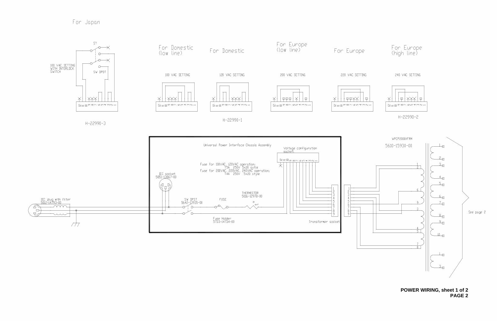
POWER WIRING, sheet 1 of 2 PAGE 2

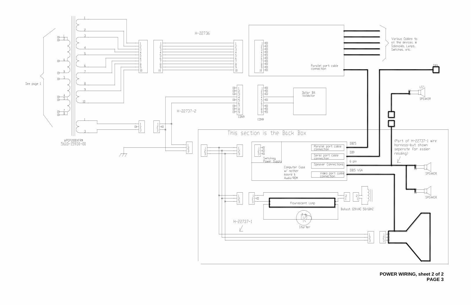
POWER WIRING, sheet 2 of 2 PAGE 3

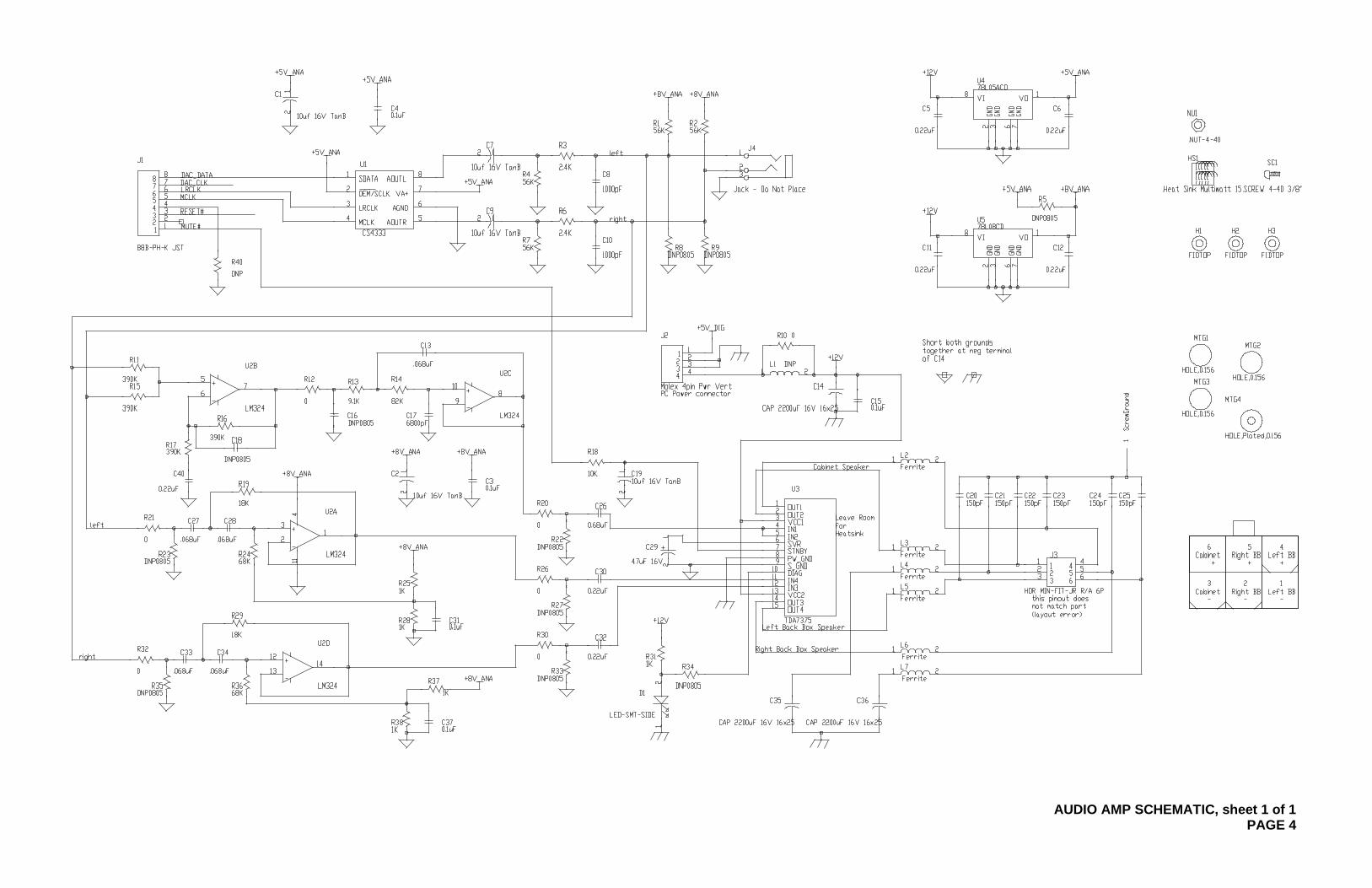
AUDIO AMP SCHEMATIC, sheet 1 of 1 PAGE 4

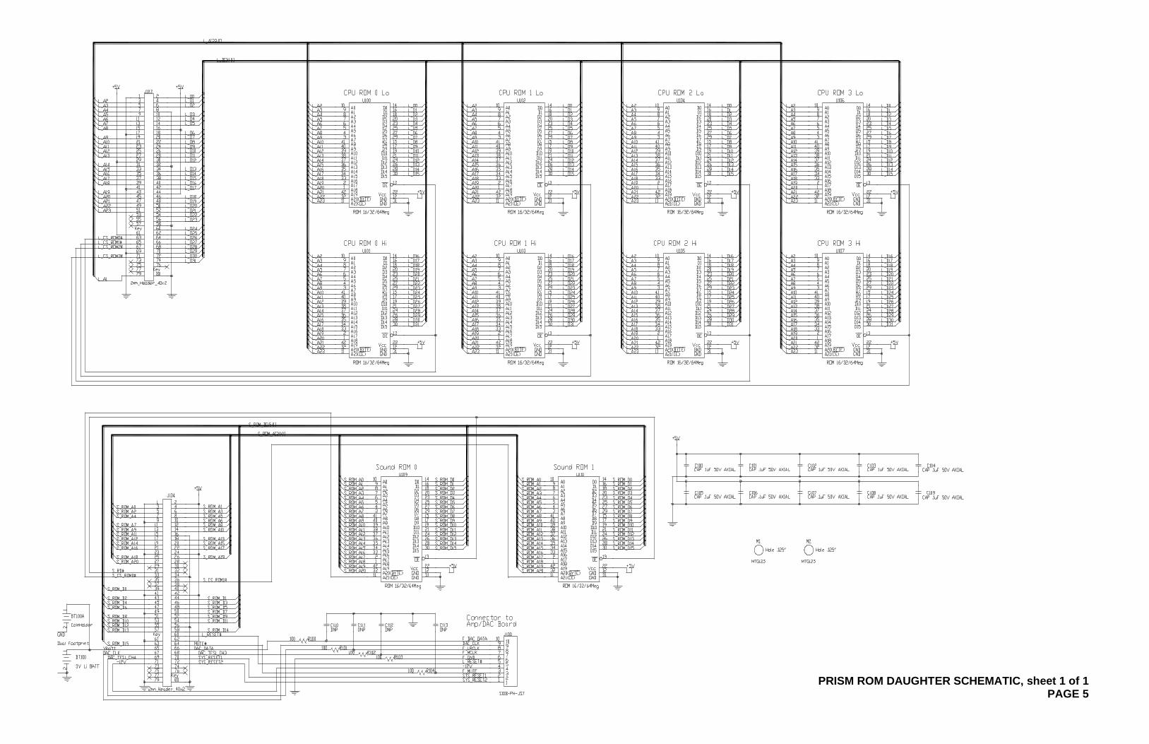
PRISM ROM DAUGHTER SCHEMATIC, sheet 1 of 1 PAGE 5

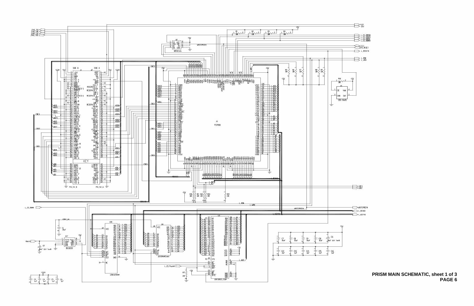
PRISM MAIN SCHEMATIC, sheet 1 of 3 PAGE 6


PRISM MAIN SCHEMATIC, sheet 2 of 3 PAGE 7


PRISM MAIN SCHEMATIC, sheet 3 of 3 PAGE 8

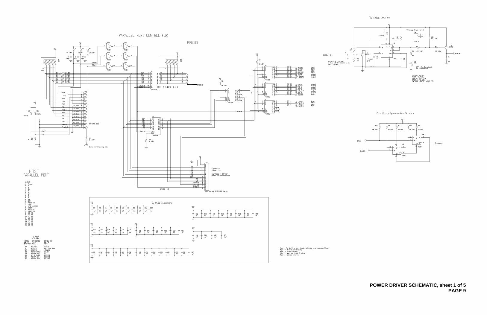
POWER DRIVER SCHEMATIC, sheet 1 of 5 PAGE 9

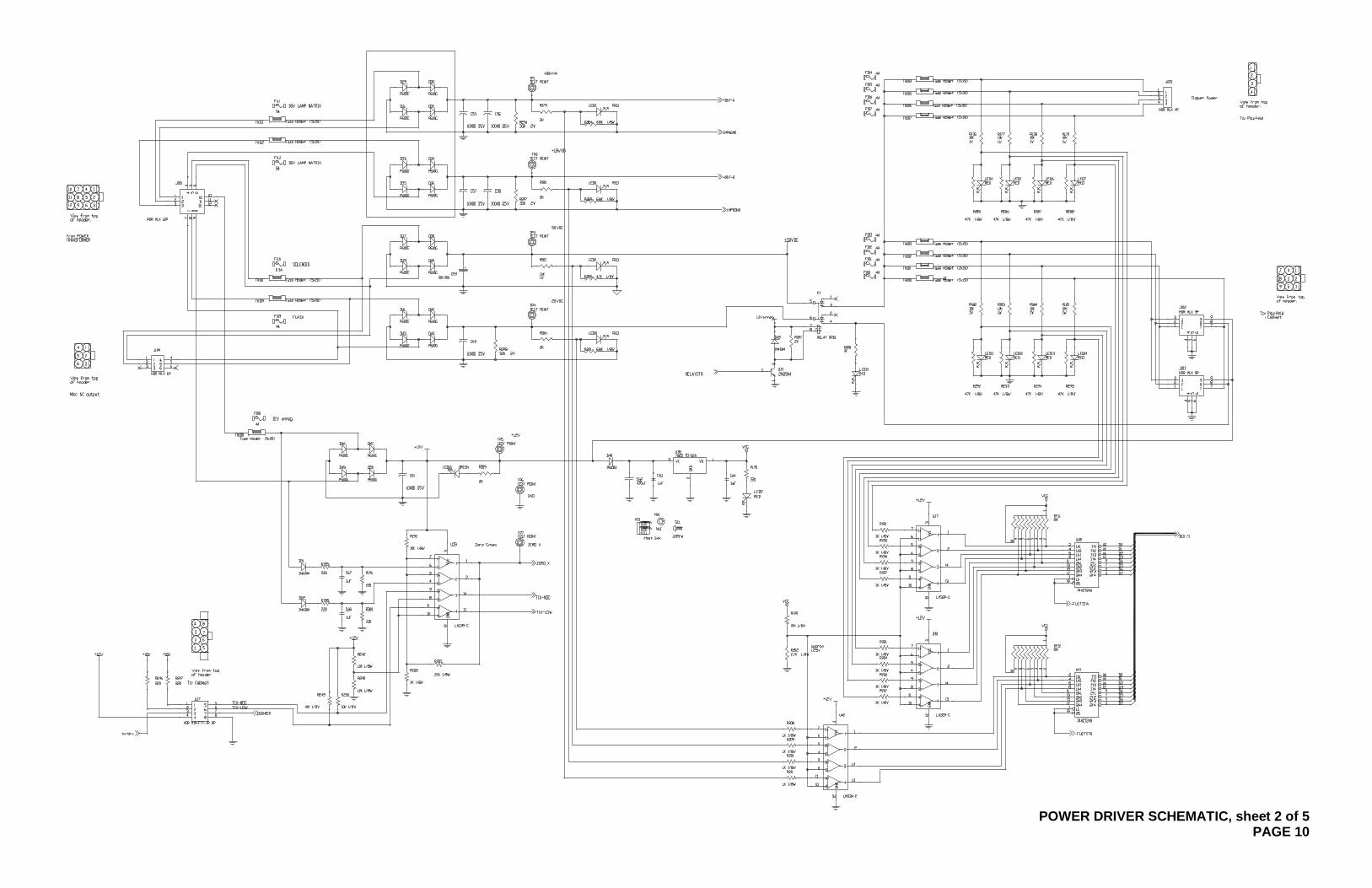
POWER DRIVER SCHEMATIC, sheet 2 of 5 PAGE 10

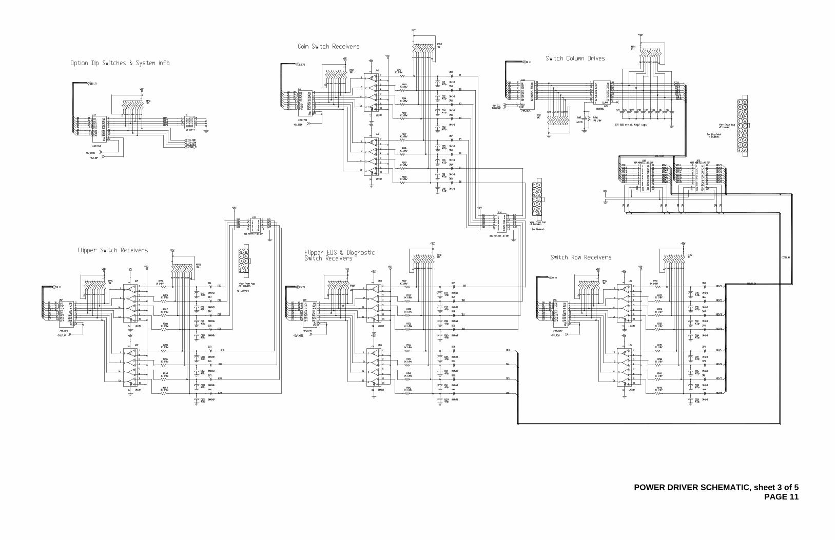
POWER DRIVER SCHEMATIC, sheet 3 of 5 PAGE 11


POWER DRIVER SCHEMATIC, sheet 4 of 5 PAGE 12


POWER DRIVER SCHEMATIC, sheet 5 of 5
PAGE 13