Pilot’s Guide - Valley Flying Club · Transferring Data from the EDM930 to a Laptop PC 28 Section...
65
Pilot’s Guide Engine Data Management EDM930 Copyright 2004 J.P. Instruments, Inc. All Rights Reserved J.P. INSTRUMENTS INC. Information: P. O. Box 7033 Huntington Beach, CA 92646 Factory: 3185 B Airway Costa Mesa, CA 92626 (714) 5575434 Fax (714) 5579840 www.jpinstruments.com (PG EDM930012) Printed in the United States of America Rev B 9/2004
Transcript of Pilot’s Guide - Valley Flying Club · Transferring Data from the EDM930 to a Laptop PC 28 Section...

Pilot’s Guide Engine Data Management
EDM930
Copyright 2004 J.P. Instruments, Inc.
All Rights Reserved
J.P. INSTRUMENTS INC.
Information: P. O. Box 7033 Huntington Beach, CA 92646
Factory: 3185 B Airway Costa Mesa, CA 92626
(714) 5575434 Fax (714) 5579840
www.jpinstruments.com (PG EDM930012)
Printed in the United States of America Rev B 9/2004

Table of Contents
Section 1 Getting Started 1 Buttons 1 Display Screen 3 RPM and MAP Section Display 3 Bar Graphs Section Display 4 Basic Scanner® Operation 4
Section 2 Interpreting Data 7 Operation for each Phase of Flight 7 Typical Normal Measurements 9 Engine Diagnosis Chart 10
Section 3 LeanFind 13 LeanFind Mode—Leaning "Rich of Peak" Method 13 LeanFind Procedure—Detailed Explanation 15 Lean Find Mode—"Lean of Peak" Method, GAMI injectors 17 Turbocharged Engines 18
Section 4 Alarms 18 Alarm Priority 19 PreIgnition and Detonation 20
Section 5 Displays and Controls 20 RPM and MAP Displays 20 Scanner® Displays 21 Bar Graph Displays 22 Remote Auxiliary Display Option 22
Section 6 Operation 23 Modes 23 Automatic Mode 23 Manual Mode 24 LeanFind Mode 24
Section 7 Fuel Flow Features 24 Fuel Management 26 Measurement Scan 27
Section 8 Memory and Data Download 28 Transferring Data from the EDM930 to a Laptop PC 28
Section 9 First Time Setup and Customization 29 Factory Program Submenus 32 Customizing the Bar Graph Display 46 Programming Alarm Limits 46
Section 10 Troubleshooting the EDM 47 Common Misapplications 47

Diagnostic Testing on Startup and During Flight 47 Diagnostic Messages 48
Section 11 Appendices 49 Features and Benefits 49 Shock Cooling 51 Navigation Data Formats 51 Connector Pin Assignments 52 Navigation Data Ports for GPS Comm 53
Section 12 Technical Support 54 Limited Warranty 54 Index 55

Product Features Chart Handsfree, automatic scanning All programming done from the Front Panel LeanFind finds the first and last cylinder to peak with true peak detect— eliminates false peaks Displays both leaned temperature below peak and peak Battery voltage with alarm Amperes (load or charge/discharge meter) Programmable alarm limits Exhaust Gas Temperatures (EGTs) to stable 1°F resolution DIF low to high EGT with alarm Shock cooling monitored on every cylinder User selectable scan indexing rate Fast response probes Nonvolatile long term memory Records and stores data up to 30 hours Postflight data retrieval Data retrieval software
Oil pressure Oil temperature Turbine inlet temperature (optional) Outside air temperature Compressor discharge temperature (optional) Carburetor temperature or induction temperature (optional) Fuel pressure (optional) Fuel level Fuel Flow Solidstate rotor fuel flow transducer Fuel quantity in gallons, kilograms, liters, or pounds Low fuel quantity alarm Low fuel time alarm GPS interface Instantaneous fuel flow rate Total amount of fuel consumed Total fuel remaining Time to empty at the current fuel flow rate
RPM and manifold pressure Automatically calculates percent horsepower History of extreme values during previous flight Hobbs® timer Remote auxiliary display (optional on nonprimary instrument)

Section 1 Getting Started
This is a summary of the basic operation. The last two pages of this manual are a Quick Reference Guide describing how to perform the most commonly used functions. Detailed descriptions of all operations appear later in this Pilot’s Guide.
To change the factory settings of your EDM930 for first time use, see Section 9 First Time Setup and Customization on page 29. You will want to do this to change the fuel tank capacity, Kfactor, alarm limits, display indexing rate, or other custom settings.
EDM900s approved as primary instruments have preset alarm limits and do not allow changing of these alarm limits and cautionary ranges for the following measurements: oil temperature, oil pressure, fuel pressure, fuel quantity, cylinder head temperature, turbine inlet temperature, manifold pressure, and RPM.
The word tap is used to denote pressing a button momentarily. The word hold is used to denote pressing and holding a button for five seconds or longer.
Buttons
Buttons, Front Panel Four operating buttons control all functions of the EDM. These buttons can change labels depending on the current state of the EDM930.
The term tap is used to denote pressing a button momentarily. The term hold is used to denote pressing and holding a button for five seconds or longer.
First Button (Step, Step/OK, Exit) • In the Automatic mode, tapping the Step button will stop the
indexing and change to the Manual mode. Then each tap of the Step button will display the next measurement in the sequence. Holding the Step button will continuously sequence in reverse order.

Page 2 Engine Data Management
• In the LeanFind mode tapping the Exit button will terminate the LeanFind mode and change to the Automatic mode.
• In the Program mode tapping the Step/OK button will advance to the next item.
Second Button (LF, RoP/LoP, Change) • In Automatic or Manual modes, tapping the LF button will
change to the LeanFind mode.
• In the LF mode holding the RoP/LoP button after peak EGT is found will display peak EGT.
First and Second Buttons • Holding both the Step and LF buttons simultaneously for
five seconds will enter the pilot programming and other modes.
• Holding both the Exit and RoP/LoP buttons simultaneously for five seconds after entering LeanFind mode but before beginning to lean will toggle between leaning “rich of peak” and “lean of peak.”
• Tapping both the Step and LF buttons simultaneously in Manual mode toggles to include or exclude the displayed measurement from the Automatic mode (except Fuel Used). No measurements are excluded from the Manual mode.
Third Button (UTC, Snap ) • T Tapping the UTC button will display the time.

For Your Safe Flight Page 3
Fourth Button (DIM ) • The DIM button lets you fine tune the automatic brightness
sensor.
• Holding the DIM button maximizes display brightness.
• Tapping the DIM button reduces the brightness in five total steps.
Fueling the Aircraft 1. At power up you will see FILL? No at the lower left side of the
screen. Tap the LF button to see FILL 75 (or whatever the capacity of your tanks are).
2. With auxiliary tanks, tap LF again to see FILL 100 (or whatever the capacity of your tanksplusauxiliary or full tanks are).
3. Tap the Step button to accept the displayed value and exit.
See page 24 for a more detailed description.
Display Screen
The display screen is arranged into three sections. The top left is the RPM andMAP section. The bottom left is the Scanner® section. And the right side is the Bar Graphs section.
RPM and MAP Section Display
The upper semicircular bar graph shows the RPM (Revolutions per Minute) and the lower semicircular bar graph shows the MAP (Manifold Pressure). These are shown both graphically and digitally. Power settings entering red line are displayed by flashing the ALERT icon and flashing a message on the bottom left Scanner® section of the screen.
Percent horsepower is displayed digitally below and to the left of the MAP arc.
Page 4 Engine Data Management
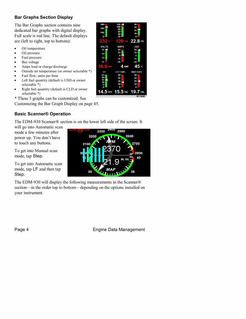
Bar Graphs Section Display
The Bar Graphs section contains nine dedicated bar graphs with digital display. Full scale is red line. The default displays are (left to right, top to bottom): • Oil temperature • Oil pressure • Fuel pressure • Bus voltage • Amps load or charge/discharge • Outside air temperature (or owner selectable *) • Fuel flow, units per hour • Left fuel quantity (default is USD or owner
selectable *) • Right fuel quantity (default is CLD or owner
selectable *) * These 3 graphs can be customized. See Customizing the Bar Graph Display on page 45.
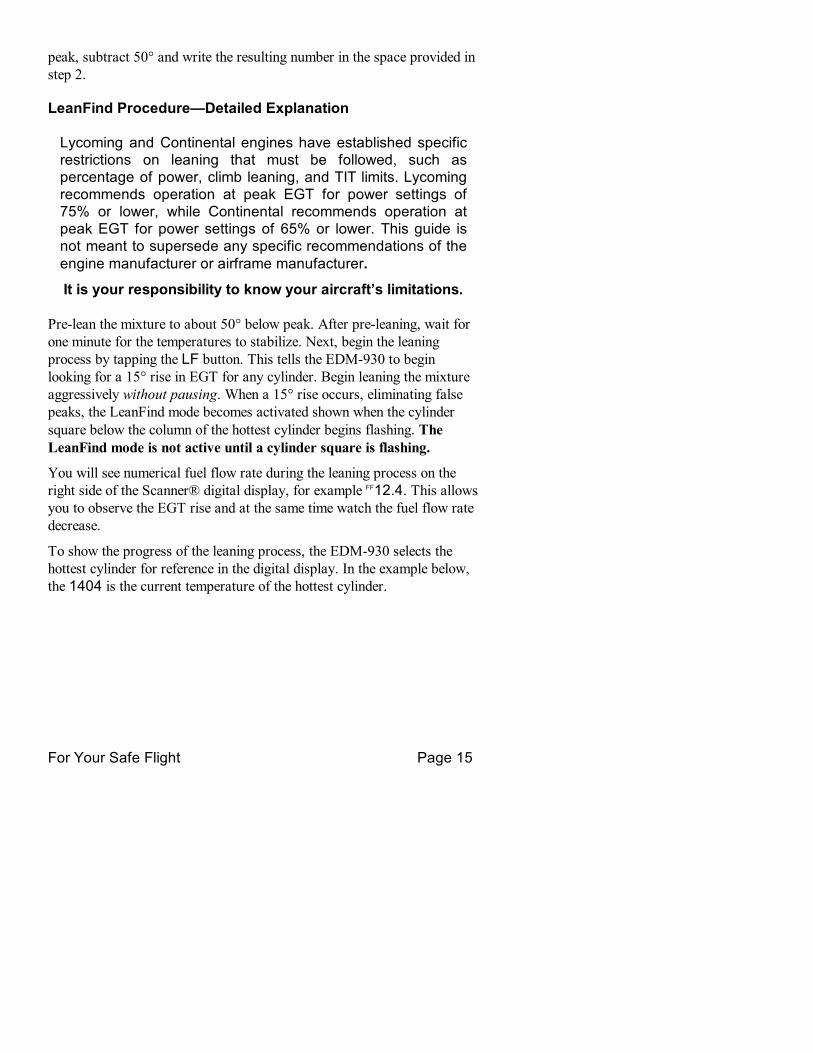
Basic Scanner® Operation
The EDM930 Scanner® section is on the lower left side of the screen. It will go into Automatic scan mode a few minutes after power up. You don’t have to touch any buttons.
To get into Manual scan mode, tap Step.
To get into Automatic scan mode, tap LF and then tap Step.
The EDM930 will display the following measurements in the Scanner® section—in the order top to bottom—depending on the options installed on your instrument.

For Your Safe Flight Page 5
Display Discription EGT 1340 CHT 376 EGT left, CHT right 1370 T I T Turbine Inlet Temperature 30 Shock Cool Rate of shock cooling 80 EGT Diff Difference between hottest and coldest EGT 300 CDT Compressor discharge option 125 IAT Induction air option 132 C I Compressor minus induction difference 22 Carb Temp Carburetor option 37.2 Fuel Remaining Fuel remaining 25.9 Fuel Required Fuel required to wpt (GPS connected) 11.3 Fuel Reserve Fuel reserve at wpt (GPS connected) 13.0 MPG Miles per gallon (GPS connected) 02:45 Endurance Fuel time to empty 38 Fuel Used Fuel used since fill or reset
EGT EGTs are shown on the left side Scanner® bar graph columns in blue. These are labeled 1 through 4 or 1 through 6 below the columns. The lower limit of the graph range represents half of the TIT alarm red line (default is 825°F) and the top of the range represents alarm red line (default 1650°F). The numerical value of the EGT is shown on the left side of the digital display for each cylinder when there is a square around one of the cylinder numbers below the column—cylinder 1 in the example. Above each column is shown its numerical EGT value.
TIT display If you have TIT, it will be shown on the right of the EGT bar graphs as a lighter colored bar and will be labeled with a T below it.
CHT The Cylinder Head Temperature—CHT— are shown on the right side Scanner® bar graph columns in green. The scale is shown to the right side of the columns. The numerical value of the CHT is shown on the right side of the digital display for each cylinder when there is a square around one of the cylinder numbers below the column. Above each column is shown its numerical CHT value.
LeanFind Simply prelean, tap the LF button and begin leaning. The EDM930 will assist you in finding the first cylinder to peak. See page 13 for a more detailed description of leaning.

Page 6 Engine Data Management
1. Establish cruise at approximately 65 to 75% power. 2. Prelean the mixture to 50°F estimated rich of peak EGT on any
cylinder. 3. Wait about 30 to 60 seconds. 4. Tap the LF button. 5. Lean the mixture aggressively—approx. 10°/second without
stopping—while observing the display. When there is a 15°F rise in EGT, LeanFind mode becomes active, indicated by the square flashing below the hottest EGT column.
6. Stop leaning when a column begins flashing. You will see leanest for two seconds, followed by—for example— EGT 1520 FF 13.8. The left number is the current temperature of the first EGT to peak and the right number is the current fuel flow.
7. If you hold RoP/LoP, peak EGT will be displayed while the RoP/LoP button is held down. Release the button for the next step.
8. Slowly enrich the mixture. The temperature will increase, returning to peak. Stop enriching at the desired EGT.

For Your Safe Flight Page 7
Section 2 Interpreting Data
Operation for each Phase of Flight
Engine RunUp (you can add this to your runup checklist.)
Suggested setup: • Set engine to runup RPM • Manual mode
Verify:• uniform rise of about 50°F in all EGTs in single magneto operation. • uniform rise of EGTs with application of the mixture control.
Be alert for: • unusually low voltage (less than nominal battery voltage) • cold OIL and normal oil pressure • abnormally high CHT • large drop in EGT on one cylinder in single magneto operation—may
be fouled spark plug.
TakeOff, Climb, and Full Throttle Operations Suggested setup:
• Automatic mode Verify:
• EGTs and CHTs consistent with past climbs. EGTs should be in the 1100 to 1300°F range (100° to 300°F cooler than cruise) due to fuel cooling.
Be alert for: • high EGT in one cylinder, 300°F above the others may indicate
plugged injector or leaking manifold gasket on a carbureted engine.
At high density altitude an overly rich mixture can significantly reduce engine power.
Cruise After the engine is warmed up, use LeanFind to lean the mixture.
Suggested setup: • Automatic mode

Page 8 Engine Data Management
Be alert for: • uneven EGTs (injected engines). Make fine adjustments to throttle,
then RPM, then mixture to level the display columns. • abnormal patterns of EGTs and CHT. (see “Engine Diagnosis Chart”
on page 10).
Descent Suggested setup:
• Manual mode Be alert for:
• CLD: shock cooling alarm is set to 60°F. Average cool rates of 40°F/minute to –60°F/minute are normal, depending on the engine size.

For Your Safe Flight Page 9
Typical Normal Measurements
The following chart lists typical normal measurement values that you will observe for most general aircraft engines. Your particular engine’s ranges may not fall within these values.
Measurement Normal range Comments EGTs in Cruise 1350°F
1550°F
• under 200 HP engines • high performance
engines • (EGT should drop
200°F when full throttle is applied)
EGT span (DIF) 70 to 90°F 120 to 150°F
• fuel injected engines • carbureted engines
TIT 1600°F average • 100° higher than EGT CHTs 350°F (OAT 60°F)
410°F
• normally aspirated engines
• Turbocharged engines CHT span 50 to 70°F • 100° with gasket probes OIL T 200°F • oil cooler thermostat
opens at 180°F OIL P 30 to 60 psi • varies with aircraft type FUEL P 1 to 18 psi • varies with aircraft type Shock cooling* 40°/minute
55°/minute 200°/minute
• tightly cowled engines • Bonanza • helicopter
* Maintain a cooling rate magnitude of less than 60°/minute. You will find that the cylinder with the greatest shock cooling will shift from front cylinders (during climb out) to the rear cylinders (during descent ).
If one CHT is reading 20° to 50° above or below the others, this may be due to that cylinder having a spark plug gasket probe instead of a bayonet probe. This is necessary because the aircraft’s factory original CHT probe is occupying the socket in the cylinder head rather than the EDM. This is normal. If the discrepancy is greater, be sure the spark plug gasket probe is mounted on the top spark plug. An adapter probe is available to occupy the same socket as the factory original probe. Contact your dealer.

Page 10 Engine Data Management
Engine Diagnosis Chart
The following chart will help you diagnose engine problems in your aircraft.
Display Symptom Probable Cause Recommended Action
TIT ~100° higher than EGTs
This is normal
75° to 100° EGT rise for one cylinder during flight
Spark plug not firing due to fouling, faulty plug, wire or distributor.
Enrich mixture to return EGT to normal. Have plugs checked.
EGT Increase or decrease after ignition maintenance
Improper timing: high EGT → retarded ignition; low EGT → advanced ignition.
Check EGT for each magneto to determine any uneven timing.
Loss of EGT for one cylinder. Engine rough
Stuck valve. Other cylinders are okay.
Have valve train checked.
Loss of EGT for one cylinder; no digital EGT
Failed probe or failed wire harness.
Swap probes to determine if probe or wire harness is bad.
Decrease in EGT for one cylinder
Intake valve not opening fully; faulty valve lifter.
Have valve lifter or rocker arm checked.
Increase in DIF at low RPM
Low compression (blow by) in cylinder
Check compression.
EGT and CHT not uniform
Normal for carbureted engines. Dirty fuel injectors or fouled plugs.
Check injectors and plugs.
Decrease in EGT for all cylinders
Decrease in airflow into the induction system. Carb or
Check for change in manifold pressure.

For Your Safe Flight Page 11
induction ice.

Page 12 Engine Data Management
Display Symptom Probable Cause Recommended Action
Slow rise in EGT. Low CHT
Burned exhaust valve. CHT is low due to low power output.
Have compression checked.
High CHT on cylinders on one side of engine
Obstruction under cowling.
Check for improper installed baffling, cowl flap misalignment or bird nests.
Rapid rise in CHT of one cylinder
Detonation. Reduce power.
Sudden off scale rise for any or all cylinders
Preignition
or failed probe
Full rich and reduce power.
Check probe
(no picture) Loss of peak EGT
Poor ignition or vapor in fuel injection system.
Have magneto tested.
(no picture) Decrease in peak or flat EGT response to leaning process
Detonation. Usually the result of 80 Octane fuel in 100 Octane engine.
Enrich mixture, reduce power and relean mixture. Repeat to find power setting where normal peak is obtained or run rich.
Below 10,000 ft. full throttle causes EGTs to rise
Weak or defective mechanical fuel pump.
Apply booster pump. If EGTs drop, replace fuel pump.
CHT more than 500°, EGT normal. Adjacent EGT may be low
Leaking exhaust gasket blowing on CHT probe.
Look for white powder around cylinder to determine leak area.

For Your Safe Flight Page 13
Section 3 LeanFind
JPI’s EDM930 provides two methods of leaning: lean rich of peak or lean of peak. The standard method is to lean about 20° rich of peak. With the advent of GAMI injectors it is now possible to set the mixture lean of peak—saving fuel and running the engine cooler. This manual primarily describes the rich of peak method, and provides the procedure for the lean of peak method. The default method is set to rich of peak. These two methods are described and depicted in the following pages.
LeanFind Mode—Leaning "Rich of Peak" Method
Simply prelean, tap the LF button and begin leaning. Upon reaching cruise configuration, you will use the LeanFind mode to identify the first cylinder to reach peak EGT.
EGT °F below
peak
Percent of best pow
er
CHT °F change fro
m
best pow
er
Best economy range
Best power range
0
200
100
300
20
20
60
40
0
80 100
85
90
95
80
EGT
CHT
Percent pow
er
Specific fuel consumption
Over lean
Lean Rich Full Rich (Takeoff)
Leaner Mixture
Peak Power
First cyl inder to peak. Use Rich of Peak leaning
Last cylinder to peak. Use Lean of Peak leaning with GAMI injectors
GAMI spread

Page 14 Engine Data Management
LeanFind Procedure—StepbyStep
Procedure Example Comments
1 Establish cruise at approx. 65 to 75% power.
2 Prelean the mixture to 50°F estimated rich of peak EGT on any cylinder: _____°
1490 370 *For your first flight with the EDM, use the method shown below.
3 Wait one minute Let engine stabilize.
4 Tap the LF button Rich/Peak Start LeanFind. (Optionally, after starting Leanfind, to change to “Lean/Peak” method, hold both Exit and RoP/LoP simultaneously.)
5 Lean the mixture aggressively— approximately 10°/second without pausing—while observing the display. When there is a 15°F rise in EGT, LeanFind mode becomes active.
1520 13.8 Flashing cylinder square indicates hottest cylinder and that LeanFind mode is active.
6 Stop leaning when a column begins flashing. You will see “Leanest” for two seconds, followed by: 1545 12.4
Flashing cylinder square & column indicates leanest cylinder. Due to thermal inertia this will usually be about 15°F lean of peak.
7 If you hold LF, peak EGT will be displayed while the LF button is held down.
1560 12.4 Captured peak EGT value is displayed.
8 Slowly enrich the mixture. The temperature will increase, returning to peak. Stop enriching at the desired EGT.
Best economy Best power
1560 13.8
1560 13.8 1460 14.2
• Peak EGT for best economy
• 100° rich of peak for best power
Best power
Temperature when column flashes
best economy
leaner richer
*Determining the prelean value: while in cruise at under 65 percent power, choose any cylinder and lean that cylinder to peak EGT in the Manual mode or to engine roughness, whichever occurs first. Note the
For Your Safe Flight Page 15
peak, subtract 50° and write the resulting number in the space provided in step 2.
LeanFind Procedure—Detailed Explanation
Lycoming and Continental engines have established specific restrictions on leaning that must be followed, such as percentage of power, climb leaning, and TIT limits. Lycoming recommends operation at peak EGT for power settings of 75% or lower, while Continental recommends operation at peak EGT for power settings of 65% or lower. This guide is not meant to supersede any specific recommendations of the engine manufacturer or airframe manufacturer.
It is your responsibility to know your aircraft’s limitations.
Prelean the mixture to about 50° below peak. After preleaning, wait for one minute for the temperatures to stabilize. Next, begin the leaning process by tapping the LF button. This tells the EDM930 to begin looking for a 15° rise in EGT for any cylinder. Begin leaning the mixture aggressively without pausing. When a 15° rise occurs, eliminating false peaks, the LeanFind mode becomes activated shown when the cylinder square below the column of the hottest cylinder begins flashing. The LeanFind mode is not active until a cylinder square is flashing.
You will see numerical fuel flow rate during the leaning process on the right side of the Scanner® digital display, for example FF 12.4. This allows you to observe the EGT rise and at the same time watch the fuel flow rate decrease.
To show the progress of the leaning process, the EDM930 selects the hottest cylinder for reference in the digital display. In the example below, the 1404 is the current temperature of the hottest cylinder.

Page 16 Engine Data Management
Continue leaning smoothly without stopping. With a vernier mixture control, turn the knob about a quarter turn every second. With a non vernier or quadrant mixture control, lean slowly and smoothly about 1/16 inch every five seconds. Eventually, one cylinder will reach peak before any of the other cylinders. The EDM930 will determine this automatically. Notice that this cylinder is not necessarily the hottest.
The EDM930 will indicate success in finding a peak by displaying the words Leanest for two seconds, followed by flashing the column and displaying the value of the EGT of the cylinder that peaked first. The current fuel flow rate will be displayed on the right side of the digital display. The flashing cylinder will be locked—or set—into the digital display during the remainder of the LeanFind procedure to allow you to set the final mixture. The peak EGT value is remembered by the EDM 930 and will be displayed as long as you hold the RoP/LoP button.
You may now enrichen the mixture to operate at peak or continue enriching to 100° rich of peak, or a value of your choice, consistent with the procedures defined in your aircraft engine manual. If you tap the RoP/LoP button, the digital display will toggle to show the EGT spread (delta EGT).
If you lean too much, the EGT will drop and the engine will be operating lean of peak.
Leaning Rich of Peak

For Your Safe Flight Page 17
Lean Find Mode—"Lean of Peak" Method, GAMI injectors
To use the “lean of peak” method, tap LF and then immediately hold both Exit and RoP/LoP until you see Lean/Peak. You may toggle back to Rich/Peak by holding both buttons again. Once you begin leaning (flashing square) you cannot change leaning method. Upon power up, the EDM930 always defaults to Rich of Peak mode.
Leaning Lean of Peak
In the “lean of peak” method the columns will invert with the first to peak progressing down from the top of the display. The inverted column scale has higher sensitivity. As you continue to lean past peak the square of the each successive cylinder will flash as it peaks. The peaks will be shown as an inverted Scanner® bar graph column; when the last cylinder peaks its column will flash. The analog display is an inverted bar graph showing where each cylinder peaked. When the RoP/LoP button is held the

Page 18 Engine Data Management
display will show the delta fuel flow between the first and last to peak (GAMI Spread), as well as the richest peak EGT.
Turbocharged Engines
The leaning process for turbocharged engines is by reference to the first cylinder or TIT to reach peak. However, the TIT factory red line may limit the leaning process. TIT red line is generally 1650°F, and up to 1750°F in some installations. In the LeanFind mode the T column— TIT—is included in the procedure. If during leaning the TIT exceeds red line by less than 100° for less than one minute, the LeanFind procedure will continue to operate, allowing you to complete the leaning process. Otherwise the digital display will show, for example, 1650 TIT and TIT will flash. You may notice that in some cases the TIT reads 100°F hotter than the hottest EGT. JPI HastaloyX probes produces faster response with long life and are more accurate than the massive factory installed probe. Therefore JPI probes may read as much as 100°F higher than the factory installed TIT probe. However, note that the engine was certified with the factory installed TIT probe and gauge, and this gauge reading is the limiting factor when adjusting your engine.
Section 4 Alarms
The EDM930 has programmable alarms. When a measurement falls outside of its normal limits, the ALERT icon will flash and the digital display will flash with the value and abbreviation of the alarming item. If the condition triggering the alarm returns to within normal limits, the ALERT icon and the display will stop flashing.
If a remote auxiliary display option is installed, it too will show the alarm condition and the label will flash, for example:
The Display Unit option is described on page 22.
The pressure alarms become armed when any EGT exceeds 500°F or the RPM exceeds the Hobbs RPM enable value.
For Your Safe Flight Page 19
The DIF measurement is the difference between the hottest and coolest EGTs. DIF—or span—is the important measurement—and associated alarm—for monitoring the EGTs. See “Factory Set Default Limits” on page 46 for a list of the alarms and their factory default settings.
To disable alarm for 10 minutes: when an alarm is displayed, tapping the Step button will temporarily disable the alarm digital indication for the next ten minutes.
To disable alarm for the remainder of the flight: when an alarm is displayed, holding the button until the words Alarm Off appears will disable that alarm digital indication for the remainder of the flight, or until the unit is turned off and on again. See “Alarm Limits” on page 45.
Alarm Priority
If multiple alarms occur simultaneously, the higher priority alarm will temporarily “mask” the lower priority alarm(s). Primary alarms will always have higher priority than nonprimary alarms. When an alarm occurs, note the cause of the alarm and tap the Step button to clear the alarm indication so that you will be notified of any other alarm that might have occurred. In primary instruments, the remote auxiliary display will cycle through all active primary alarms and cannot be cleared until the alarm condition no longer exists. The alarm priorities are as follows:
Highest priority
CHT High CHT
OIL High OIL temperature TIT High TIT Shock Cool Excessive CHT cooling rate EGT Span Excessive EGT span BUS High battery voltage BUS Low battery voltage RPM RPM over redline EGT High EGT MAP Overboost Manifold pressure Oil Press. High oil pressure Oil Press. Low oil pressure Fuel Pressure High fuel pressure Fuel Pressure Low fuel pressure Low Fuel Alarm Low fuel quantity remaining

Page 20 Engine Data Management
Lowest priority
Minutes Low fuel endurance remaining
PreIgnition and Detonation
Combustion that is too rapid leads to detonation and possibly preignition. Detonation is abnormally rapid combustion where the fuelair mixture explodes instead of burning uniformly. It causes the EGT to decrease and the CHT to increase, and can appear during the leaning process. It occurs under high compression from fuel with too low an octane rating, or from avgas contaminated by jet fuel. Fuel additives, such as lead, boost the octane rating and slow down the combustion process, producing an even pressure to the piston.
Preignition is caused by hot spots in the cylinder. Ignition occurs prior to the spark plug firing. The EDM930 depicts preignition as a sudden red line of the EGT on the analog display. This may occur in one or more cylinders. The affected cylinder column(s) will flash while the digital display will show an EGT higher than 2000°F. At this temperature pre ignition will destroy your engine in less than a minute unless you take immediate corrective action.
Section 5 Displays and Controls
The EDM930 monitors engine temperatures and voltages, assists in adjusting the fuel/air mixture, and helps diagnose engine malfunctions. There are multiple components of the user interface:
• RPM and MAP display in the upper left corner of the display • Scanner®® analog display including cylinder number and index
square in the lower left corner of the display • Scanner® digital display for numeric readouts and messages at the
bottom left • Bar graph displays on the right half of the display • Four front panel operating buttons below the bottom of the display.
RPM and MAP Displays
The upper left side of the display shows RPM above the MAP. The arcs

For Your Safe Flight Page 21
represent the analog values. Below the arcs is shown the percent horsepower.
Scanner® Displays
Scanner® Analog Display
The lower left side of the display is the Scanner® with %HP above it.
The following is a description of the Scanner® analog display, from top to bottom. Numbers in circles refer to features in the above diagram.
Temperature Units (°F or °C) • °F temperatures in the digital display are in Fahrenheit degrees. • °C temperatures in the digital display are in Celsius degrees.
The bar graph scale remains the same. To change the display of engine temperatures see “Factory Program Submenus” on page 32. Cylinder Numbers and Index A row of numbers 1 through 6 are the column labels for the analog displays. The 1 through 6 are the cylinder numbers. If the TIT function is installed, it will be displayed to the right of the EGTs above the letter T. A square around a number 1 through 6 indicates that particular column is shown numerically in the EGT and CHT digital display.
Scanner® Bar Graph EGT and CHT The total height of each column represents the EGT and the CHT. The EGT and TIT temperature resolutions depend on the programmed red line limits.

Page 22 Engine Data Management
Scanner® Digital Display Beneath the Scanner® bar graph is the alphanumeric display.
EGT and CHT When the index square is around a cylinder number, 1 through 6, the digital display shows the EGT on the left (four digits) and the CHT on the right (three digits) for that cylinder.
Bar Graph Displays
There are nine bar graphs shown on the right side of the display. The default measurements displayed are (left to right, top to bottom):
• Oil temperature, • Oil pressure, • Fuel pressure, • Bus voltage, • Amps load or charge/discharge, • OAT, • Fuel flow, • Left tank fuel level, and • Right tank fuel level.
The top of the bar is redline and the bottom of the bar is zero for OT, F P, amps load and fuel. For amps charge/discharge the center of the bar is zero and the top and bottom is maximum charge and discharge, respectively, with discharge flashing. For volts the top of the bar is high redline and the bottom of the bar is low redline..
The ranges and alarm values are user settable and are described later in section Section 9 First Time Setup and Customization on page 29.
Remote Auxiliary Display Option
The remote auxiliary display is standard on primary instruments. The remote auxiliary display option is available on nonprimary instruments for redundancy and to allow positioning a smaller display directly in front of the pilot. This auxiliary display will
For Your Safe Flight Page 23
normally show RPM and MAP, but will display a flashing alarm message, duplicating the alarm indication of the Scanner® digital display, for example:
Section 6 Operation
Modes
The EDM930 has four different operating modes: Automatic, Manual, Program and LeanFind. When you first turn on the power the EDM930 starts in the Manual mode, but will enter the Automatic mode after a few minutes. The Automatic mode provides you with engine monitoring information for the majority of flight conditions. To adjust the mixture, use the LeanFind mode. And to display specific measurements, use the Manual mode. In both the Automatic and Manual modes the analog display shows a Scanner® bar graph of EGT and CHT for each cylinder and the TIT.
Automatic Mode
Just tap the LF button, then tap the Step button. In the Automatic mode the EDM930 displays the measurement sequence at a userselected rate.
Individual nonprimary measurements can be excluded from the Automatic mode: tap Step to enter the Manual mode. Tap Step repeatedly to index to the measurement you want to exclude. Then tap both the Step and LF buttons simultaneously. Excluded measurements display a decimal point before the measurement name. For example:
Included: 1540 CDT Excluded: 1540 .CDT Tapping the Step and LF buttons simultaneously will toggle back and forth between include and exclude.
• Every time you turn on the EDM, all measurements are reset to be included.
• All installed measurements are always displayed in the Manual mode. Exclusion only applies to the Automatic mode.

Page 24 Engine Data Management
• All measurements are checked for alarm conditions every second regardless of their included or excluded status.
Manual Mode
Just tap the Step button. Use the Manual mode when you want to monitor one specific measurement such as shock cooling during descent, or a particular cylinder temperature during climbs. To change to the Manual mode, tap the Step button once. Subsequent taps will index the digital display through the measurement sequence. To exit the Manual mode and return to the Automatic mode, tap the LF button and then tap the Step button. You may disable the Automatic mode by setting “0” for scan rate.
LeanFind Mode
This was described in Section 3 LeanFind, beginning on page 13.
Section 7 Fuel Flow Features
Start Up Fuel After initial selftest, you will be asked to inform the EDM930 of start up fuel. The EDM930 will display FUEL for one second, and then flash FILL? No . If your aircraft has tank fill tabs and no auxiliary tanks, you can use the auxiliary tank feature to select either filling to the tank tabs or topping the tank. See page 36 to program the EDM930 for this feature. The EDM930 does not differentiate fuel flow between the main and auxiliary tanks; it considers only total fuel in the aircraft. During flight you may also inform the EDM930 of startup fuel using the pilot program mode display if you forgot to do so at start up. The EDM 930 will retroactively calculate the fuel consumed.

For Your Safe Flight Page 25
auxiliary tank
main tank with tab tab
Aux capacity
Main capacity Main tank
Refer to the column in the chart below corresponding to your fuel tank configuration. Tap the LF button to select one of the four following fueling choices on the left column of the chart.
LF to choose⇓
Main tanks only, no tabs
Main tanks with tabs
Main & Auxiliary tanks
FILL? N Did not add any fuel since last shutdown. FILL 75 * Topped the
main tanks. Filled only to the tabs.
Topped the main tanks. If some additional fuel is added to the auxiliary tanks, you will input this next when .0 GAL is displayed
FILL I20 * (not available)
Topped the main tanks.
Topped both the main and auxiliary tanks.
FILL + Did not top, but added additional fuel to the aircraft, or removed fuel from the aircraft.
* These values are customize for your aircraft.
Then tap the Step button to complete the entry and advance to the Manual mode.
Adding Fuel and Auxiliary Tanks If you added less than full fuel to only the main tanks then select FILL + and the next display will ask you how much you added: .0 GAL (or selected units). Hold the LF button to count up, tap the LF button to count down. The count up will stop at full tanks, since you cannot add more fuel
Page 26 Engine Data Management
than would top the tanks. If you added fuel to only the main tanks, then input how much you added. If you topped the main tanks, but have some fuel remaining in the auxiliary tanks, input how much is now in the auxiliary tanks. You can “add” a negative amount of fuel if you remove fuel from the aircraft or wish to correct the total quantity of fuel on board.
Accumulate Total—Trip Total You may either display total fuel used since the last time you informed the EDM930 that the aircraft was refueled, or for an extended trip with multiple fuel stops. This selection affects only the Fuel Used measurement.
Resetting “Fuel Used” Every time you inform the EDM930 that the aircraft is refueled, the amount of fuel used is set to zero, unless the instrument is programmed to accumulate or you are in flight. The display of fuel used pertains only to the fuel used since the last time you informed the EDM930 that the aircraft was refueled. To reset to zero the amount of fuel used at any point in time, manually Step to display Fuel Used and hold both Step and LF buttons for five seconds until the display shows .0 USD.
Fuel Management
For fuel calculations to be accurate, it is imperative that you inform the EDM930 of the correct amount of fuel aboard the aircraft. Do not rely on fuel flow instruments to determine fuel levels in tanks. Refer to original fuel flow instrumentation for primary information
The EDM930 Fuel Flow monitor uses a small, turbine transducer that measures the fuel flowing into the engine. Higher fuel flow causes the transducer turbine to rotate faster which generates a faster pulse rate. Because the transducer turbine generates thousands of pulses per gallon of fuel, it can measure the amount of fuel that flows into the engine with high resolution. Prior to engine start you inform the EDM930 Fuel Flow monitor of the known quantity of fuel aboard, and it will keep track of all fuel delivered to the engine. During flight you may also inform the EDM930 of startup fuel using the pilot program mode display if you forgot to do so at start up.

For Your Safe Flight Page 27
Measurement Scan
Listed below is the sequence, measurement description and example of the digital display.
Measurement Description EXAMPLE COMMENTS
EGT, CHT 1340 376 EGT, left, CHT, right. Square indicates cylinder
TIT, Turbine Inlet Temperature
1370 TIT Turbine #1
Shock Cooling 30 Shock Cool
Square indicates fastest cooling cylinder
Compressor Discharge Temperature
300 CDT Into intercooler
Induction Air Temperature
125 IAT Out of intercooler
CDTIAT 132 C I Difference of CDT and IAT
Carburetor Temperature
22 Carb Temp
Not available when CDT is installed
Difference between hottest and coldest EGT
80 DIF Square indicates most widely deviating cylinder
Fuel Remaining 37.2 Fuel Remaining
In gallons, liters or pounds or kilograms
Fuel required to next GPS WPT or Destination
25.9 Fuel Required
Present with GPS interface valid signal and way point
Fuel Reserve at next GPS WPT or Destination
11.3 Fuel Reserve
Present with GPS interface valid signal and way point
Nautical Miles per Gal
13.0 MPG Present with GPS interface and valid signal or MPK, MPL, MPP
Time to Empty 02:45 Endurance
Hours.minutes remaining at current fuel burn
Total Fuel Used 38 Fuel Used Since last refueling or trip total.

Page 28 Engine Data Management
Section 8 Memory and Data Download
The EDM930 Long Term Data Memory will record and store all displayed measurements once every six seconds (or at the programmed interval of between 2 to 500 seconds). At a later time it will transfer them directly to a laptop PC.
When you retrieve recorded data to your laptop PC you can choose to retrieve all the data in stored in the EDM, or only the new data recorded since your last retrieval. In either case, no data in the EDM930 is erased. The retrieved data will be saved in the PC in a file in a compressed format. The supplied PC program will decompress the data for display and use by other programs, such a MS Excel.
The amount of total data that the EDM930 can store will vary depending on how rapidly the measurements change. The typical storage is 20 hours at a 6 second intervals (1666 hours at 500 second intervals), but may vary depending on which options are installed. When the memory becomes full, the oldest data will be discarded to make room for the newest. You may place a mark at the next data record by tapping the Snap button. You will see the word SNAP at the next record snapshot, indicating a data record has been marked. Recording begins when EGTs are greater than 500°F or “snap” is requested.
All data are timestamped. You may also program an aircraft id that will appear in the output data file. The aircraft id can be your aircraft registration number or your name. Initially the aircraft ID is set to FACTORY.
You may change the record interval from 2 to 500 seconds, even in flight. When you change the interval in flight, the current flight file is closed, and a new flight file is created with the new record interval.
Transferring Data from the EDM930 to a Laptop PC
Install EzPlot™ on your laptop PC, following the instructions included with the EzPlot. Connect to the computer serial port using the supplied serial cable or to the USB port using an optional Keyspan USB Serial Adapter (available from JPI; install the serial adapter driver). Insert the small round plug into the data connector on the EDM930, and the other

For Your Safe Flight Page 29
end into the computer serial port or to the USB port using the Keyspan adapter. Both types of connections are shown below.
On the Windows desktop double click EzPlot icon. Click on the Download and Archive Data from Your EDM button.
Follow the instructions on the screen. After the data is downloaded DONE will be displayed. EzPlot program will decompress the data file that was downloaded, and produce individual Flight files.
OR
Keyspan U
SB
Adapter
USA19Q
W
Laptop
DATA PORT
EDM 900
DATA PORT
EDM 900
USB port 1
6
5
9
serial port
Section 9 First Time Setup and Customization
Pilot Program
Pilot Programming Using EzConfig
JPI provides a configuration program that runs on an MSWindows PC, called EzConfig. See the www.jpinstruments.com web site to download. Follow the instructions in the EzConfig documentation to change these assignments.

Page 30 Engine Data Management
Pilot Programming without EzConfig
To start the Pilot Program procedure, simultaneously hold the Step and LF buttons for five seconds. You will see the word PROGRAM for two seconds and then the sequence shown in the chart below. Tap the Step/OK button to advance to the next item in the list. Hold the Step/OK button to step back to the previous item. Tap the Change button to select alternate values of that item. Simultaneously hold both Step/OK and Change to exit. Step/OK advances next item
Change sequences
through these values
Comments
PROGRAM Stays on for two seconds. FUEL No FILL ? No Tap Change to change fuel status. See
page 24à Exits program mode when done.
Rec Rate (secs) 4
0 … 9 Index rate (pause time in seconds) in the Automatic Mode. 0 disables the Automatic Mode.
OAT F OAT F ⇔ OAT C
To calibrate the OAT ±10°, hold both the Step/OK and Change buttons simultaneously for five seconds, which will proceed to the next step. Otherwise the next step will be skipped.
OAT+0 OATI0 … OAT+I0
This step will be normally be skipped. Adjust the indicated temperature up or down by up to 10°. For example, OAT+3 adjust the OAT 3° higher.
EGT in 1’s ? No
EGT in 1’s ? Yes ⇔ EGT in 1’s ? No
Y—Yes—sets the digital display to one degree resolution; N—No—sets 10°. (10° resolution is easier to interpret the EGTs.)
HP Constant= I25
70 hp
HP Constant= I25
%HP display will change when HP constant is adjusted. Hold Step/OK and Change for 5 seconds until you see ADJUST to set the HP calibration. Tap Step/OK to continue to the next step. See page 31à

For Your Safe Flight Page 31
Trip? No Trip? No ⇔ Trip? Yes
N—No—Upon informing the EDM that you refueled the aircraft, reset total fuel used to 0. Y—Yes—accumulate total fuel used rather than reset to 0 at each refueling. See page 31à
HOBs Value
2424 Engine⇔ 25 EDM⇔ 3567 FRM
Displays the engine hours and airframe hours.
END? Yes END? Yes Step/OK exits the pilot program mode. Change reenters pilot program mode.
Programming the Horsepower Constant You must adjust the HP Constant once for your aircraft. You must perform this adjustment in the air while the aircraft is in flight between 5,000 and 8,000 feet MSL.
1. Enter the pilot program mode by simultaneously holding the Step and LF buttons for five seconds.
2. Tap Step/OK repeatedly until you see—for example— HPConstant=125. Then hold both the Step/OK and Change buttons display until you see Adjust, followed by HP Constant=125. The adjustment range for the HP Constant is 45 to 180.
3. Set the MP and RPM per your POH to 70 percent power. Let conditions stabilize.
4. Change the HP reading on the EDM930 to 70 percent by adjusting the HP constant in the lower display by holding or tapping the Change button. Percent HP should be close to 100 percent during takeoff at sea level.
5. Tap the Step/OK button to proceed to the next step.
Programming Accumulate Trip Total Accumulate—default is OFF: resets the fuel used to 0 every time you inform the EDM930 that the aircraft was refueled. With accumulate ON fuel used will not be reset to 0 when you inform the EDM930 that the aircraft was refueled.

Page 32 Engine Data Management
Select “No” if you wish to display total fuel used since the last time you informed the EDM930 that the aircraft was refueled. Select “Yes” to display total fuel used for an extended trip with multiple fuel stops. This selection affects only the Fuel Used measurement.
During normal operation, to reset the accumulated fuel used display at any time, tap Step until you see USD. Hold both Step and LF until the display shows .0 USD.
Factory Program Submenus
EDM900s approved as primary instruments have preset alarm limits do not allow changing of these alarm limits and cautionary ranges for the following measurements: oil temperature, oil pressure, fuel pressure, fuel quantity, cylinder head temperature, turbine inlet temperature, manifold pressure, and RPM. Alarm limits marked with the notation PRIMARY cannot be changed.
Factory Programming Using EzConfig
JPI provides a configuration program that runs on an MSWindows PC, called EzConfig. Follow the instructions in the EzConfig documentation to change these assignments.
Factory Programming Without EzConfig To enter the factory programming submenus:
• Simultaneously hold the Step and LF buttons for five seconds. You will see FUEL ? No.
• Again, release and simultaneously hold the Step/OK and Change buttons for five seconds. You will see Configuration Menu on the top of the screen and Temperature? N on the bottom.
Tap the Step/OK button to advance to the next item in the list. Hold the Step/OK button to step back to the previous item. Tap Change to enter the desired submenu. When you exit the last item on a submenu the display will show ++++ +++ for a second and then display the next item. To immediately exit the Factory Program mode, hold the Step/OK and Change buttons for five seconds.

For Your Safe Flight Page 33
The name of the submenu that you are currently stepping through is displayed on the upper left side of the screen. Initially the display will be Configuration Menu.
Tap Step/OK to answer “no,” you do not want to enter the displayed submenu. Tap Change to answer “yes,” you do want to enter the displayed submenu.
Submenus Step/OK Change enters this submenu Temperature ? N
Sets the engine temperature units, calibrates TIT and thermocouple type. See page 33à
Alarms ? N Sets the alarm limits for battery voltages, engine temperatures, fuel and other parameters. See page 34à
Fuel Flow ?N Sets the tank capacities and other constants for the fuel flow transducer system.
RPM ? No Sets the number of cylinders for the RPM sensor and the Hobbs enable RPM. See page 39à
Record ?N Sets the data recording time interval. See page 40à MAP ? No Sets the manifold pressure calibration. See page 40à Fuel Level ?N Sets the fuel level parameters. See page 41à N Number ?N Sets the aircraft ID, registrations number, or owner into the
EDM for initial startup and for use in reports. Time ?N Sets the time and date. See page 45à Electrical ?N Sets whether a second electrical bus exists and whether the
amp meter(s) is(are) load or charge/discharge. See page 45 à
HPWR ? No Sets horsepower for lean of peak calculations. TRBO? No Selects turbo charged aircraft for lean of peak calculations. END ? Y Step/OK exits the Factory Limit mode.
Change reenters factory programming mode.
Tap Change to enter the desired submenu. Within each submenu there are a number of choices. Choose an item within a submenu by tapping the Step/OK button to step through the list. Tap or hold Change to choose a value for that item. Use the Step/OK button to advance to the next item.
Temperature MENU Sets the engine temperature units, calibrates TIT and thermocouple type

Page 34 Engine Data Management
Step/OK Change EGT CHT Engine F ⇔Engine C Select F or C degrees for all engine
temperatures. Same bar graph scale. Original TIT Original TIT N ⇔
Original TIT Y Original TIT, Y will enter TIT calibration mode, next step
CAL TIT TIT –975 ⇔ 975 For example, if the EDM reads 100 less than the aircraft’s TIT gauge, set the display to read T I T +I 00
Type K Type K ⇔ Type J Toggles CHT between thermocouple type K and type J (type K is JPI standard)
Alarms MENU Sets the alarm limits for battery voltages, engine temperatures, fuel and other measurements.
Step/OK Change Bus Voltage Hi Bus 10.0 à 35.0 High bus voltage limit (volts)
Low Bus 8.5 à 30.0 Low bus voltage limit (volts) EGT Span Alarm
EGT Span 30 à 990 EGT difference limit (°F or °C)
CHT HI Alarm Hi CHT 90 à 500 PRIMARY. High CHT limit (°F or °C)
Shock Cooling Alarm
Shock Cool 5 à 200 Shock cooling limit (°F or °C)
TIT Alarm TIT 650 à 2000 PRIMARY. TIT and EGT limits (°F or °C)
Oil Temp Alarm
Hi Oil Temp 40à 500 PRIMARY. High oil temperature limit (°F or °C)
Low Oil Temp 10 à 250 PRIMARY. Low oil temperature limit (°F or °C)
Oil Press. Alarm
Hi Oil Pressure 0à 150 PRIMARY. High oil pressure limit (psi)
Low Oil Pressure 0 à 100 PRIMARY. Low oil pressure limit (psi)
Hi MAP Alarm MAP 25.0 à 60.0 PRIMARY. High manifold pressure limit (in Hg)
Low Fuel Alarm
Remaining = 0 à200 Low fuel amount remaining limit (gal)
Time Remaining
Minutes= 0 à 60 Low time fuel alarm limit (minutes)

For Your Safe Flight Page 35
Fuel Press. Alarm
Hi Fuel Pressure 0à 100 PRIMARY. High fuel pressure limit (psi)
Low Fuel Press. 0 à 100 PRIMARY. Low fuel pressure limit (psi)
Max RPM Alarm
RPM 2000 à 3600 PRIMARY. High RPM limit (rev. per minute)
Max Amps Alarm
Amps= 0 à 300 High amp load limit
Max Amps 2 Alarm
Amps= 0 à 300 High amp load limit for second amps (set to 0 to disable)
Page 36 Engine Data Management
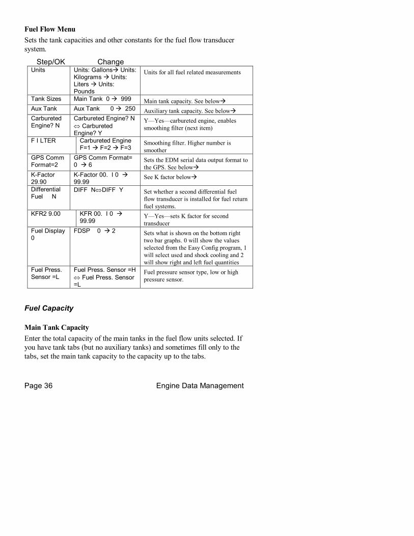
Fuel Flow Menu Sets the tank capacities and other constants for the fuel flow transducer system.
Step/OK Change Units Units: Gallonsà Units:
Kilograms à Units: Liters à Units: Pounds
Units for all fuel related measurements
Tank Sizes Main Tank 0 à 999 Main tank capacity. See belowà Aux Tank Aux Tank 0 à 250 Auxiliary tank capacity. See belowà Carbureted Engine? N
Carbureted Engine? N ⇔ Carbureted Engine? Y
Y—Yes—carbureted engine, enables smoothing filter (next item)
F I LTER Carbureted Engine F=1 à F=2 à F=3
Smoothing filter. Higher number is smoother
GPS Comm Format=2
GPS Comm Format= 0 à 6
Sets the EDM serial data output format to the GPS. See belowà
KFactor 29.90
KFactor 00. I 0 à 99.99
See K factor belowà
Differential Fuel N
DIFF N⇔DIFF Y Set whether a second differential fuel flow transducer is installed for fuel return fuel systems.
KFR2 9.00 KFR 00. I 0 à 99.99
Y—Yes—sets K factor for second transducer
Fuel Display 0
FDSP 0 à 2 Sets what is shown on the bottom right two bar graphs. 0 will show the values selected from the Easy Config program, 1 will select used and shock cooling and 2 will show right and left fuel quantities
Fuel Press. Sensor =L
Fuel Press. Sensor =H ⇔ Fuel Press. Sensor =L
Fuel pressure sensor type, low or high pressure sensor.
Fuel Capacity
Main Tank Capacity Enter the total capacity of the main tanks in the fuel flow units selected. If you have tank tabs (but no auxiliary tanks) and sometimes fill only to the tabs, set the main tank capacity to the capacity up to the tabs.

For Your Safe Flight Page 37
Auxiliary Tanks If you do not have auxiliary tanks or tank tabs, leave Aux Tank set to 0. Otherwise input the capacity of the auxiliary tanks in the fuel flow units selected. If you have tank tabs and sometimes fill only to the tabs, set the auxiliary tank capacity to the difference between full tank capacity and tab capacity. The EDM930 does not differentiate fuel flow between the main and auxiliary tanks; it tracks only total fuel in the aircraft.
Setting GPSC Fuel Flow Communications Format GPSC Input to GPS; output of EDM
0 No fuel data output 1 Garmin (Shadin Miniflow format) to waypoint 2 Allied Signal (format B to waypoint 3 Arnav/EI fuel data to waypoint 4 Allied Signal (format C) to waypoint 5 (Not used) 6 Garmin 430/530/295, UPS fuel/air data to waypoint 7 Garmin 430/530/295, UPS fuel/air data to destination 8 Allied Signal (format C) to destination
K factor
The K factor is shown on the fuel flow transducer as a fourdigit number, which is the number of pulses generated per gallon of fuel flow. Before installing the transducer, write down the K factor here _________. To enter the number, move the decimal point three places to the left. For example if the K factor on the fuel flow transducer is 29,123, enter 29.12 in the K factor parameter.
If the K factor is increased, the indicated fuel flow will decrease, and vice versa. When the K factor is changed during a trip, calculations of fuel used, fuel remaining and time to empty are not retroactively recalculated.
Fine Tuning the K factor
The K factor shown on the fuel flow transducer does not take into account your aircraft’s particular installation. Fuel hose diameters and lengths,

Page 38 Engine Data Management
elbows, fittings and routing can cause the true K factor to be different from that shown on the fuel flow transducer.
You must use the following procedure to fine tune the K factor.
1. Make at least three flights of about two to three hours each. Note the actual fuel used (as determined by topping the tanks) and the EDM 930 calculation of the fuel used for each flight USD.
Flight Fuel USED shown by EDM
(total tank REM) Actual fuel used by topping tanks 1 2 3
Total
2. Total the EDM930 calculated fuel used and the actual fuel used.
3. Record the current K factor here____________________ and in the table below.
4. Calculate the New K factor as follows:
New K factor = (EDM fuel used) x (Current K factor) (actual fuel used)
New K factor = ( ) x ( ) ( )
Every time you fine tune the K factor, change it by only half of the amount calculated above, and record the measurements here:
Date EDM fuel used
actual fuel used
Current K factor
New K factor = x/
Pilot’s initials

For Your Safe Flight Page 39
Programming the K factor This procedure is different than for setting other parameters.
1. If you haven’t already done so, start the Pilot Program procedure, by simultaneously hold the Step/OK and Change buttons for five seconds. You will see the word PROGRAM, followed by FUEL ? No.
2. Again, simultaneously hold the Step/OK and Change buttons for five seconds. You will see Configuration Menu.
3. Tap Step/OK button to advance to the Fuel Flow ?N screen. 4. Tap Change to enter the fuel flow submenu. 5. Tap Step/OK repeatedly until you see KFactor = 29.90 (for example) 6. Hold both the Step/OK and Change buttons simultaneously for five seconds. The first digit flashes (shown here as a larger digit only for illustration purposes): 29.90
7. Tap or hold the Change button to change flashing digit: 19.90 8. Tap Step/OK button for next digit (hold Step/OK for previous digit): 19.90
9. Tap or hold the Change button to change flashing digit: 18.90 10. Tap Step/OK button for next digit (hold Step/OK for previous digit): 18.90
11. Repeat items 9 and 10 for the remaining two digits. 12. Hold Step/OK and Change buttons simultaneously for five seconds to exit the K factor parameter setup.
13. Tap Step/OK repeatedly until you see END ? Yes, then Tap Step/OK once more to exit the factory setup mode.
RPM Menu Sets the number of cylinders for the RPM sensor and the Hobbs enable RPM.
Step/OK Change RPM Factor 6
RPM Factor 4 à12 PRIMARY. RPM Factor = number of pulses per revolution
HOBS ON RPM 800 à I 500 Minimum RPM to enable to Hobbs counter
RPM Factor Set the RPM Factor to 4 or 6, depending on your engine. Exceptions:

Page 40 Engine Data Management
• 4 cylinder engine with dual (allinone) magnetos set to RPM Factor 8.
• 4 cylinder Laser ignition set to RPM Factor 8. • 6 cylinder Laser ignition set to RPM Factor 12.
Record Menu Sets the data recording time interval.
Step/OK Change Rec Rate (sec)
RATE 2 à 510 Record time interval, in seconds
MAP MENU Sets the manifold pressure calibration (an sets the oil pressure and fuel pressure zero points.
Step/OK Change MAP ? No MAP 20 à 32 Manifold pressure calibration
Do this one time and only if the MAP on your manifold pressure gauge doesn't match the MAP shown on the EDM930
You must do this on the ground with the engine turned off.
Use one of the following two methods to calibrate the MAP.
A. Easy calibration: set the EDM930 MAP to the same value as shown on your aircraft’s manifold pressure gauge. Tap or hold the Change button to change the MAP value.
Or
B. Absolute calibration: the table below shows the MAP for a given field elevation (down the left side of the table) and altimeter setting (along top row of the table). Find the entry in the table most closely matching your field elevation and current altimeter setting. Interpolate if necessary. Alt setting> field elev.
29.0 29.2 29.4 29.6 29.8 29.9 30.0 30.2 30.4 30.6 30.8 31.0
0 29.0 29.2 29.4 29.6 29.8 29.9 30.0 30.2 30.4 30.6 30.8 31.0 1000 28.0 28.2 28.4 28.5 28.7 28.8 28.9 29.1 29.3 29.5 29.7 29.9 2000 27.0 27.1 27.3 27.5 27.7 27.8 27.9 28.1 28.3 28.5 28.6 28.8 3000 26.0 26.2 26.3 26.5 26.7 26.8 26.9 27.1 27.2 27.4 27.6 27.8 4000 25.0 25.2 25.4 25.6 25.7 25.8 25.9 26.1 26.3 26.4 26.6 26.8

For Your Safe Flight Page 41
5000 24.1 24.3 24.5 24.6 24.8 24.9 25.0 25.1 25.3 25.5 25.6 25.8 6000 23.2 23.4 23.6 23.7 23.9 24.0 24.0 24.2 24.4 24.5 24.7 24.8 7000 22.4 22.5 22.7 22.8 23.0 23.1 23.1 23.3 23.5 23.6 23.8 23.9
Unless your airfield is close to sea level, do not set MAP to the local altimeter setting since that setting is the pressure corrected to sea level, and is not the same as your field elevation pressure.
Tap or hold the Change button to change the MAP value.
Tap the Step/OK button to proceed to the next item.
Fuel Level Menu Use this to initially calibrate the fuel level senders. The JPI EzFuel program can be used to simplify this procedure. Visit www.jpinstruments.com to download.
Step/OK Change Fuel Level Sensor
Type N à Type Là Type F
N – none, F – fuel flow REM and USD, L – Fuel level, proceeds to next step.
FUELLVL PTS ? 2 à PTS ? 5 Number of fuel level calibration points from 2 to 5.
0000 000 L1 See Entering the Fuel Level Calibration Points, page 44 below à
TYP Type selects what the last two graphs in the bar graphs section display. N will leave them blank, F will display fuel flow derived REM and USD, and L will display fuel levels, left and right.
Determining Calibration Points First determine how many fuel level calibration points you wish to use. If your tanks or fuel senders are nonlinear, use more points. Otherwise use just 2. Select the row in the table below to determine how to calibrate your fuel level indicator.
Number of calibration points L1 & R1 L2 & R2 L3 & R3 L4 & R4 L5 & R5 2 unusable Full Not used Not used Not used

Page 42 Engine Data Management
3 unusable ½ tank Full Not used Not used
4 unusable 1/3 tank 2/3 tank Full Not used
5 unusable ¼ tank ½ tank ¾ Tank Full
Refer to FAR §23.959 to determine how to establish the unusable fuel level.
The following is the procedure to initially calibrate your fuel senders. You should only have to do this once. You will determine the 2 to 5 fuel level calibration points for one tank and write them in the chart below. You may use these values for the other tank also. If the calibration for the two tanks differ too much, then measure the calibration points for the other tank separately. These values will be entered using the procedure, Entering the Fuel Level Calibration Points, in the next subsection.
Left fuel level calibration point Right fuel level calibration point
Left Cal Left Fuel Right Cal Right Fuel
L1 [ ] [ ] [ ] [ ] [ 0] [ 0].[ 0]* R1 [ ] [ ] [ ] [ ]
[ 0] [ 0].[ 0]*
L2 [ ] [ ] [ ] [ ] [ ] [ ].[ ] R2 [ ] [ ] [ ] [ ]
[ ] [ ].[ ]
L3 [ ] [ ] [ ] [ ] [ ] [ ].[ ] R3 [ ] [ ] [ ] [ ]
[ ] [ ].[ ]
L4 [ ] [ ] [ ] [ ] [ ] [ ].[ ] R4 [ ] [ ] [ ] [ ]
[ ] [ ].[ ]
L5 [ ] [ ] [ ] [ ] [ ] [ ].[ ] R5 [ ] [ ] [ ] [ ]
[ ] [ ].[ ]
* unusable fuel level is entered as 00.0
You may choose to do this procedure totally on one tank, then the other tank, rather than moving the fuel hose back and forth between the left and right tanks.
NEVER add or remove fuel from the aircraft when the master switch is turned on.

For Your Safe Flight Page 43
Turn OFF the aircraft master switch Empty left and right tanks and fill each to the unusable level (first fuel level calibration point)
Hold the rightmost button while turning ON master switch, see Display Fuel Calibration Level
With the left and right tanks empty, write down the displayed calibration values L1 & R1. This is the empty (0) fuel level.
Turn OFF the aircraft master switch Add fuel to the left and right tanks and bring it up to the second fuel level calibration point level (or full for a two point calibration)
Hold the rightmost button while turning ON master switch, see Display Fuel Calibration Level
With the left and right tanks at the second calibration point, write down the displayed calibration values L2 & R2 and the amount of fuel now in each tank. For a 2 point calibration, stop here.
Turn OFF the aircraft master switch Add fuel to the left and right tanks and bring it up to the third fuel level calibration point level (or full for a three point calibration)
Hold the rightmost button while turning ON master switch, see Display Fuel Calibration Level
With the left and right tanks at the third calibration point, write down the displayed calibration values L3 & R3 and the amount of fuel now in each tank. For a 3 point calibration, stop here.
Turn OFF the aircraft master switch Add fuel to the left and right tanks and bring it up to the fourth fuel level calibration point level (or full for a four point calibration)
Hold the rightmost button while turning ON master switch, see Display Fuel Calibration Level
With the left and right tanks at the fourth calibration point, write down the displayed calibration values L4 & R4 and the amount of fuel now in each tank. For a 4 point calibration, stop here.
Turn OFF the aircraft master switch Add fuel to the left and right tanks and bring it up to full for the fifth fuel level point calibration point level.
Hold the rightmost button while turning ON master switch, see Display Fuel Calibration Level

Page 44 Engine Data Management
With the left and right tanks at the fifth calibration point, write down the displayed calibration values L5 & R5 and the amount of fuel now in each tank (fuel tanks).
Proceed to the next step below to enter the fuel level calibration points.
Entering the Fuel Level Calibration Points This procedure is used to enter the fuel level calibration points (2 to 5 points for each tank) into the EDM930. This procedure assumes that you have determined the calibration points from the procedure described in the Determining Calibration Points section, above.
Each fuel level calibration point is a seven digit number: the left four digits are the internal EDM930 calibration constant, and the right three digits are the corresponding fuel level in fuel units (gallons, kilograms, liters, or pounds).
In the Fuel Level menu, first select the number of fuel calibration points: 2 through 5, using Change, then tap Step/OK. You will see the first point as 0000 00.0 or some other number if calibration points have been previously entered. To the right of this display you will see the point number L1 thru L5, R1 thru R5. To change each fuel level calibration point, hold both Step/OK and Change for five seconds until the first digit flashes. Tap or hold Change to set the first digit. Tap Step/OK to advance to the next digit (hold Step/OK to go back to the previous digit). Hold both Step/OK and Change when you are finished entering this fuel level calibration point. The digit will stop flashing.
Tap Step/OK to advance to the next fuel level calibration point. Repeat the steps in the preceding paragraph for each fuel level calibration point. For 2 point calibration there will be a total of 4 constants, up to a 5 point calibration of 10 constants.
Tap Step/OK to exit the procedure.
N Number Menu Sets the aircraft ID, registrations number, or owner into the EDM for initial startup and for use in reports.
00000 àZZZZZ (1 st char flashes)
Current aircraft ID. To change aircraft ID, hold both Step/OK and Change until the first character flashes.

For Your Safe Flight Page 45
00000 àZZZZZ (2 nd char flashes, etc.)
Change the character, Step/OK moves to the next character. To save, hold both Step/OK and Change.
Time Menu Sets the time and date.
Step/OK Change Date Month 1à 12 Month
Day 1 à 31 Day Year 1 à 99 Year
Time Hour 0 à 23 Time of day, hours, 24hour time Minutes 0 à 59
Electrical Menu Sets the amps and battery measurement parameters.
Step/OK Change Bus Voltage 2 ? N
Bus Voltage 2 ? N ⇔ Bus Voltage 2 ? Y
Selects second bus voltage measurement is installed.
Amps 2 ? N Amps 2 ? N ⇔ Amps 2 ? Y
Selects second amps measurement is installed.
Amps 1 ? L Amps 1 ? L ⇔ Amps 1 ? C
Selects amps 1 measurement is load (L) or charge/discharge (C)
Amps 2 ? L A Amps 2 ?L ⇔ Amps 2 ?C
Selects amps 2 measurement is load (L) or charge/discharge (C)
HPWR Menu HPWR ? No HPWR 0 à 999 If you use lean of peak method for
leaning, set HPWR to the nominal horsepower of the engine.
TRBO Menu TRBO? No TRBO? No ⇔
TRBO? Yes If you use lean of peak method for leaning, set TRBO ? Yes if your engine is turbocharged.
1 2 3
4 5 6
7 8 9

Page 46 Engine Data Management
Customizing the Bar Graph Display
The bar graph display has 9 stations, 3 of which can be reconfigured to display any of the measurements that can appear in the Scanner® section. Stations 6, 8 and 9 can be reconfigured. Factory defaults are: station 6 OAT, station 8 USD and station 9 CLD. JPI provides a configuration program that runs on an MSWindows PC, called EzConfig. Follow the instructions in the EzConfig documentation to change these assignments.
Programming Alarm Limits
Factory Set Default Limits—NonPrimary JPI conservatively sets the default alarm limits below Lycoming and Continental recommendations.
Measurement Default Low Limit Default High Limit CHT 450°F 230°C OILT 90°F 32°C 230°F 110°C OILP 15 psi 100 psi TIT 1650°F* 900°C Shock Cool 60°F/min. 33°C/min. EGT DIF 500°F 280°C BUS, 24 V 24V 36V BUS, 12 V 12V 18V AMPS MAP 40 inHg Low Fuel 45 min Endurance 10 gal, kg, ltr, lbs FuelP 15 psi 60 psi RPM RL 2700 REM 10 gal H . M 45 minutes
If you change the display between Fahrenheit and Celsius, alarm limits will automatically change also. The bar graph scale will remain the same.
When an alarm is displayed, tapping the Step/OK button will temporarily ignore that alarm from the sequence for the next ten minutes. Or holding the Step button until the word Alarm Off appears will ignore that alarm for the remainder of the flight.

For Your Safe Flight Page 47
Section 10 Troubleshooting the EDM
Common Misapplications
Some of the more common misapplications made by firsttime EDM930 users are presented here in an attempt to help you avoid similar problems.
Problem Situation Correction LeanFind finds a “peak” too soon.
Failure to prelean before performing LeanFind or pausing while leaning.
Continue to lean without pausing.
Leaning too slowly. Lean more aggressively.
Peak not found Lean Find not activated or stopping while leaning
Lean at the speed of approximately 10°F per second.
No display of %HP, only RPM displayed
Fuel flow not reading, OAT not reading
Fuel Flow reading and OAT is required for HP.
RPM reads 2/3 of correct value
4 cylinder engine but set to 6 cylinder.
In Pilot Program change 6 to 4 cylinder.
First cylinder to peak is not the hottest
This is normal. The first to cylinder peak is not necessarily the hottest.
EGTs rise during single magneto check
This is normal, due to incomplete combustion persisting longer.
EGTs not uniform during low power operation
This is normal. Fuel and air distribution is not optimal at low power settings.
Diagnostic Testing on Startup and During Flight
When your EDM930 is first turned on the EDM930 tests internal components, calibration and integrity of the probes.
During flight, probes are constantly checked for inconsistent or intermittent signals. A faulty channel or probe encountered during startup

Page 48 Engine Data Management
or during flight will be deleted from the sequence, producing a missing column or blank digital data.
Diagnostic Messages
Startup and Operational Diagnostics The following displays indicate a malfunction in the system: ENG ON Indicates that the engine is running while trying to
calibrate the MAP. Turn off engine and try again. MEM ON Not an error. Memory on. Recording is enabled when
EGT exceeds 500°F or the RPM exceeds the Hobbs RPM enable value.
HOBS ON Not an error. Hobbs on. RPM exceeds the Hobbs RPM enable value.
TEST I NG Change tapped during self test. Tap Change again later.
0.0 GPH Zero’s indicate Fuel flow is too low to register GPH Dashes indicate No fuel flow transducer signals H.M Dashes indicate No fuel flow transducer signals OPEN PRB Open probe. Wiring to probe is open circuit. Check
wiring and crimps. Swap probes to troubleshoot. BADPRB Bad probe. Erratic reading. May be poor electrical
connection. Swap probes to troubleshoot. H I xx High. Measurement over range. LO XX Low. Measurement under range. CAL ERR Calibration error. Return unit to factory. DSP XXX Internal communication error. Return unit to factory. COMM ERR Internal communication error. Return unit to factory. NO I 5 MV Calibration error. Return unit to factory. NO 50MV Calibration error. Return unit to factory. NO 2.5V Calibration error. Return unit to factory.

For Your Safe Flight Page 49
GPS Interface Diagnostics Measurements Fuel Required, Fuel Reserve, & MPG are all missing from the scan.
No communications from GPS receiver to EDM. Possibly no connection or aircraft GPS is off.
NO COM message and measurements Fuel Required, Fuel Reserve, & MPG are missing.
Communications are received by EDM 930 and the AutoProtocol setup is in process. Verify correct output format setup in GPS receiver; check GPS connections.
NO SIG message and measurements Fuel Required, Fuel Reserve, & MPG are missing.
GPS receiver has insufficient signal for valid data.
NO WPT message and measurements Fuel Required & Fuel Reserve, are missing.
No waypoints are programmed into the aircraft GPS receiver.
Fuel Required or Fuel Reserve message
Your ground track is more than ±70° from your course to the next GPS waypoint.
History Display Upon power up you can see the history of extreme values during previous flight. To do this, hold the Step button during initial power up of the EDM930. The bar graph section of the display will show the extreme value of each measurement for a minute or until you tap the Step button. History cannot be displayed other than at power up. It will remain in the display until RPM exceeds Hobbs On RPM value or the EGT is above 500°F.
Section 11 Appendices
Features and Benefits
The EDM930 Engine Data Management system is the most advanced and accurate piston enginemonitoring instrument on the market. Using the latest microprocessor technology, the EDM930 will monitor up to twentyfour critical measurements in your engine, four times a second,

Page 50 Engine Data Management
with a linearized thermocouple accuracy of better than 0.1 percent or 2 F°.
As your builtin flight engineer, the EDM930 is constantly “red line” checking: all critical measurements are automatically checked four times a second, regardless of the current display status. Leaning is accomplished quickly and automatically using the LeanFind procedure. With the EDM930 it is now possible to have substantially more diagnostic information available to you in a timely and usable manner.
The realtime serial data port—a standard feature—permits you to externally record scanned measurements in realtime using a laptop PC. The builtin data recording will continue to operate.
Benefits of Proper Mixture Control • Improved engine efficiency • Reduced maintenance costs • Greater fuel economy • Reduced operating costs • Smoother engine operation • Proper engine temperatures • Longer spark plug life • Reduced engine vibration
JPI Probes Temperature information processed by the EDM930 is captured by fast response, grounded JPI temperature probes, that accurately measure the small temperature changes—as small as 1°F—that occur during mixture adjustment.
Temperature and Mixture In a piston engine only a small portion of the energy from combustion produces movement of the piston during the power stroke. The majority of energy passes into the exhaust pipe as hot gasses. By monitoring the temperature of these exhaust gasses you will have an indication of the quality of the combustion process. Low compression, nonuniform fuel distribution, faulty ignition, and clogged injectors diminish the efficiency of the combustion process that generates power.
CHT probe
EGT probe
cylinder head
exhaust manifold

For Your Safe Flight Page 51
From the cockpit you can adjust the fuel/air ratio by a process called leaning. Retarding the mixture control changes the fuel/air ratio and hence the resulting Exhaust Gas Temperature (EGT).
The following figure depicts the mixture and temperature relationship.
As the mixture is leaned, EGT rises to a peak temperature, and then drops as the mixture is further leaned. Peak power occurs at a mixture using more fuel than at peak EGT. Best economy occurs at peak EGT. Accurate leaning yields optimal engine temperatures. By being able to precisely adjust the mixture, your engine can produce either the best fuel economy or maximum power, whichever you choose.
Shock Cooling
Cooling the cylinders too fast can result in cracking and eventual failure. Lycoming Service Instruction 1094D (March 25, 1994) on Fuel Mixture Leaning Procedures states:
“At all times, caution must be taken not to shock cool the cylinders. The maximum recommended temperature change should not exceed 50°F per minute.”
JPI checks shock cooling on all cylinders displaying the highest reading cylinder.
Navigation Data Formats
Output of GPS; input to EDM. The EDM930 automatically configures itself for one of three industry standard data formats:
Format Baud rate
NMEA183 (Marine Nav Data Format)
4,800 This is the format for most handheld GPS receivers. Loran must have sentences RMA & RMB. GPS must have sentences RMB & RMC.
Aviation Data Format
9,600 “Output sentence type 1” Required sentences are: A, B, C, D, E, I and L first character identifier byte. Sentence terminator may be either <CR><LF> or <CR> alone.
Northstar (Northstar binary)
1,200 M1 setup select “NO EXTENDED”, “NAV ONLY”

Page 52 Engine Data Management
Connector Pin Assignments P1 Options 25pin connector
P3 MAPRPM 9pin connector
P4 Fuel Flow 15pin connector
Pin no.
Pin no.
Probe or function
Pin no.
Function/ sensor pin
Pin no.
Function
yel 1 red 2 OIL grn 1 RPM sig /1 1 out to GPS yel 3 red 4 IND blk 2 RPM grd /2 2 in from GPS yel 5 red 6 CARB* red 3 RPM pwr /3 3 yel 14 red 15 OAT red 4 MAP pwr /3 wht 4 FF signal yel 16 red 17 TIT1 blk 5 MAP grd /1 red 5 FF power yel 18 red 19 TIT2 6 OIL P sig blk 6 FF ground
7 OIL P grd gry 12 Remote alert T,V wht 8 MAP sig+ /2
11 remote FF alarm
red 13 + Power grn 9 MAP sig /4 wht 12 FF2 signal red 13 FF2 power wht 11
wht 24 data in data out 14 AMPS 2 +
15 AMPS 2 blk 25 Engine ground
*Displays as CRB if IAT probe is not present; displays as CDT is IAT if present.
P2 EGT CHT 25pin connector
P5 FP/FQ/AMP 15pin connector
Pin no.
Pin no.
Probe or function
Pin no.
Function
yel 1 red 2 CHT 1 1 FQ 1 (res) yel 3 red 4 CHT 2 2 FQ 2 (res) yel 5 red 6 CHT 3 3 FQ grd yel 7 red 8 CHT 4 4 FP Sig+ yel 9 red 10 CHT 5 5 FP Sig yel 11 red 12 CHT 6 6 FP pwr yel 14 red 15 EGT 1 7 FP grd yel 16 red 17 EGT 2 8 yel 18 red 19 EGT 3 9 FQ1 sig (cap) yel 20 red 21 EGT 4 10 FQ2 sig (cap) yel 22 red 23 EGT 5 11 FQ1 pwr (cap) yel 24 red 25 EGT 6 12 FQ2 pwr (cap)
13 Volts 2 sense 14 AMPS + 15 AMPS

For Your Safe Flight Page 53
Interface connections to selected GPS models
EDM930 P4 conn Pin 1 P4 conn Pin 2 Arnav 5000 Pin 4 Pin 5 Garmin 195 (nc) Pin 4 Garmin 430 / 430 Pin 57 Pin 56 Northstar M3P (nc) Pin 6 (leave pin 11
open) UPS GX50 / 60 Pin 4 Pin 5
Navigation Data Ports for GPS Comm
(These ports are completely independent of the EDM930 serial data output port.) Navigation Data (output from GPS; input to EDM)
Compatible with RS232, TTL, RS423, RS422 SDA.
Serial data format: 8 data, 1 start, no parity. Baud rates: 1,200, 4,800, or 9,600 depending on the GPS data output format. The EDM 930 automatically detects the GPS data output format and is independent of the GPSC setting.
Fuel Data (input to GPS; output from EDM) RS232. Serial data format: 8 data, 1 start, no parity. Baud rate: 9,600.

Page 54 Engine Data Management
Output format is determined by the GPSC setting, but may be over ridden by the GPS navigation format: If the EDM930 senses Northstar or NMEA183 navigation data input, there will be no fuel data output.
Section 12 Technical Support
JPI offers both email and telephone technical support. Have your model and serial number ready when you call. Call JPI for a return authorization number before returning any equipment.
J.P. INSTRUMENTS Inc. 3185 B Airway Costa Mesa, CA 92626 800 3454574 www.jpinstruments.com [email protected]
Limited Warranty J.P. Instruments Inc. (JPI) warrants all parts in your new EDM930 to be free from defects in material and workmanship under normal use. Our obligation under this warranty is limited to repair or exchange of any defective part of this unit if the part is returned, shipping prepaid, within two years for electronics and one year for probes from the date of original purchase. Installation labor is the responsibility of the aircraft owner. Homebuilt aircraft warranty starts when the aircraft is certified for flight. Replacement parts carry a warranty for the balance of the warranty period.
Under this warranty, JPI is not responsible for any service charges, including removal, installation, nor any other consequential damages. JPI incurs no obligation under this warranty unless a Warranty Registration Certificate describing the warranted product has been completed and mailed to JPI with all information requested.
This warranty is void on any product which has been subject to misuse, accident, damage caused by negligence, damage in transit, handling or modification which, in the opinion of JPI, has altered or repaired the product in any way that effects the reliability or detracts from the performance of the product, or any product whereon the serial number has been altered, defaced, effaced or destroyed.
This warranty is in lieu of all other warranties expressed or implied and other obligations of liability on JPI’s part, and it neither assumes nor authorizes any other person to assume for JPI any other liability in connection with the sale of JPI products.
To initiate this warranty, the aircraft owner must submit a completed Data Logging Worksheet to JPI. Upon receiving a completed worksheet, JPI will initiate the warranty from the date of original purchase. Any replacement parts carry a warranty that extends for the balance of the period of the original warranty. For homebuilt aircraft the warranty starts when the aircraft is certificated for flight and noted on the warranty card.
For Your Safe Flight Page 55
Index
A Accumulate, 29, 30
total, 25 Adapter probe, CHT, 9 Adding fuel, 24 Adjusting
K factor, 35 OAT, 29 TIT, 31, 32, 33, 34, 37, 38, 39
Alarm priority, 18 resetting, 17
Alarm limits factory defaults, 44 fuel flow, 34
Alarms, 17 Alerts, 17 Allied Signal, 35 Arnav, 35 Automatic mode, 22 Auxiliary display, 17 Auxiliary tanks, 35 Avgas, 18 Aviation data format, 49
B Bar graph, 4, 20, 21
column resolution, 20 configure, 28, 31, 44
Baud rate, 51 Blinking display, 13, 17, 19 Button
DIM, 2 LF, 2 RoP/LoP, 2 Step, 1 Step/Ok, 1 UTC, Snap, 2
Buttons front panel, 1
C Calibration
fuel level, 39 horsepower, 30 internal self test, 45 K factor, 35 OAT, 29
Carburetor, 37 ice, 10 temperature, 26
Celsius display indicator, 20 OAT, 29
Change button, 2
CHT display, 5 probe, 9, 48 too high or too low, 9, 11
Combustion, 18, 48 Compression, 11, 48
high, 18 low, 10
Compressor discharge temperature, CDT, 26
Configure bar graph, 28, 31, 44
Connector pin assignments, 50
Cowling, obstruction, 11 Cruise, 7 Custom programming
alarm limits, 44 Customize, 28 Cylinder numbers, 20
D Data
GPS formats, 49 ports, GPS, 51
DATE menu, 43

Page 56 Engine Data Management
Default alarm limits, 44 Defueling, 24 Delete measurements, 22 Descent, 8 Detonation, 10, 11, 18 Diagnosing engine problems, 44 Diagnostic
fuel flow messages, 46 GPS interface messages, 47 self test, 45
DIF, 26 DIM, 2 Display, 20
analog, 20 CHT, 5 digital, 20 EGT, 5 flashing, 13, 17, 19 Scanner, 20 TIT, 5
E Economy, best, 49 EGT
display, 5 loss, 10 probe, 48 resolution, display, 29 too high, 10 too low, 10
ELEC menu, 43 Electronics International, 35 Eliminate measurements, 22 Engine
diagnosis chart, 10 limits, normal, 9 runup, 7
Error messages, 45 Exclude measurements, 22 Exhaust leak, 11 Exit
Factory program mode, 31 EzConfig, 28, 31, 44 EzPlot, 27
F Factory default alarm limits, 44 Factory programming, 31 Fahrenheit
display indicator, 20 OAT, 29
Failure to prelean, 45 Features, 4 Fill options, 24 FILL? N, 23 FILL+, 24 First cylinder to peak, 14 First time setup, 28 Flashing display, 13, 17, 19 Flat EGT response, 10, 11 FLVL menu, 39 Fuel
accumulate, 25 adding or filling, 24 auxiliary tank capacity, 35 capacity, 34 injectors, 11 injectors, clogged, 7, 10, 48 management, 25 Octane, 11 pump, 11 remaining, 26 removing, 24 required, 26 reserve, 26 resetting fuel used, 25 start up, 3, 23 tabs, tank, 35 tank capacity, 34 used, 26
FUEL DSP, 41 Fuel flow, 23
alarm limits, 34 connector, 50 diagnostics messages, 46
G GAMI, 12, 16 Gasket probe, 9

For Your Safe Flight Page 57
Gasket, manifold, 11 Getting started, 1 GPS
constant, 35 data formats, 49 data ports, 51 interface diagnostics, 47
H H.S, 26 Hastaloy, 17 History, 47 Hobbs®
reading, 29 set turnon RPM, 37
Holding a button, 1 Horsepower
constant setting, 30 Horsepower constant, 30
I Ice, carburetor or induction, 10 Ignition, 11
timing, 10 Include measurements, 22 Indexing
scan rate, 29 sequence, 26
Induction, 10 air temperature, IAT, 26
Informing the EDM900 startup fuel, 23
Injectors. See Fuel, injectors Intake valve, 10 Interpreting
data, 7 display, 10
Interval record, 38
K K factor
determing, 35
L Leak
manifold, 11 Lean of Peak, 16 Lean of Peak Leaning, 16 Leanest cylinder, 13 LeanFind
button, 2 mode, 12 procedure, 5, 12, 13, 14
Leaning, 48, See also, LeanFind by TIT, 16 preleaning, 14 too quickly, 45
LF. See LeanFind Long Term Memory Option
mark, 2, 27 operation, 26
Lotus 123, 27
M Magneto check, 7 Management
fuel, 25 Manual mode, 23 MAP
display, 3, 19 Mark, 2, 27 Measurement
indexing, 26 Menu
DATE, 43 ELEC, 43 FLVL, 39 RECD, 38 RPM, 37 TEMP, 31, 32, 33, 34, 37, 38, 39 TIME, 43 USER IDN, 42
Menus, 31 Methods
leaning, 12 Miles per gallon, 26 Misapplications, 45

Page 58 Engine Data Management
Missing column, 10
Mixture, 14, 48 best economy, 49 best power, 49
Modes, 22 MPG, MPK, MPL, MPP, 26 MS Excel, 27
N Nautical miles per gallon, 26 Navigation data formats, 49 NMEA183, 49 NO COM, 47 NO SIG, 47 NO WPT, 47 Normal engine limits, 9 Northstar binary format, 49
O OAT
calibration, 29 F or C, 29
Octane, 11 OFF, 17, 44 OPEN PRB, 46 Operation, 19, 22
fuel flow monitor, 23 Option connector, 50
P Peak EGT, 14 PEAK EGT, 13, 15 Pilot programming, 28
alarm limits, 44 Pin assignments
option connector, 50 Power, best, 49 Preignition, 18 Preleaning. See Leaning, preleaning Primary
preset alarm limits, 1, 30 Priority
alarm, 18 Product support, 52 Programming, 28, 31
alarm limits, 44
R Range, normal temperature, 9 Rate
baud, 51 fuel flow, 25 indexing, 29 shock cooling, 8
RECD menu, 38 Record interval, 38 Recording. See Long Term Memory
Option Red line, 9 REM, 26 Remote Auxiliary Display, 17, 21 Remove measurements, 22 Removing fuel, 24 REQ, 26 RES, 26 Reset
alarms, 17 fuel used, 25
Resolution, EGT display, 29 RF, 37 Rich of Peak, 12 RoP/LoP
button, 2 Rough engine, 10 RPM, 45
alarm, 33 display, 3, 19 menu, 37
RS232, 51 Runup, 7
S Scanner
displays, 20 Scanner®, 4 Setup, 28

For Your Safe Flight Page 59
alarm limits, 44 Shadin Miniflow, 35 Shock cooling, 8, 9, 23, 49 Snap, 2 SNAP, 2, 27 Spark plug
fouling, 7, 10 Startup
diagnostics, 45 fuel, 3, 23
Step button, 1
Stuck valve, 10
T Tabs, tank, 35 Tachometer. See RPM Tanks, fuel
capacity, 34 tabs, 23, 35
Tapping a button, 1 Technical support, 52 TEMP menu, 31, 32, 33, 34, 37, 38,
39 Test, self, 45 TIME menu, 43 Time to empty, 26 Timing, ignition, 10 TIT, 16
display, 5 Top fuel tanks. See Fill Total
fuel, 25 fuel used, 26, 30
Transducer, fuel flow, 25 Trip total, 25, 30 Troubleshooting
engine, 10 GPS, 47 instrument, 45
Trouibleshooting fuel flow, 46
Turbocharged Engines, 16
U Uniform, CHT, EGT not, 10 Unusable, 40 USB adapter, 27 USD, 26
reset, 25 USER IDN menu, 42 UTC, 2
V Valve
lifter, 10 stuck, 10
Vapor, 11
W Warranty, 52
Z Zeroing fuel used, 25
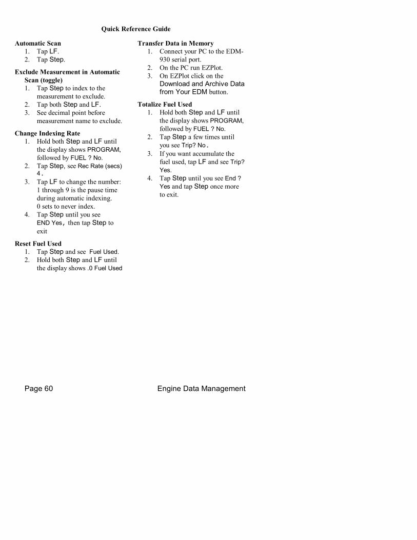
Page 60 Engine Data Management
Quick Reference Guide
Automatic Scan 1. Tap LF. 2. Tap Step.
Exclude Measurement in Automatic Scan (toggle) 1. Tap Step to index to the
measurement to exclude. 2. Tap both Step and LF. 3. See decimal point before
measurement name to exclude.
Change Indexing Rate 1. Hold both Step and LF until
the display shows PROGRAM, followed by FUEL ? No.
2. Tap Step, see Rec Rate (secs) 4.
3. Tap LF to change the number: 1 through 9 is the pause time during automatic indexing. 0 sets to never index.
4. Tap Step until you see END Yes, then tap Step to exit
Reset Fuel Used 1. Tap Step and see Fuel Used. 2. Hold both Step and LF until
the display shows .0 Fuel Used
Transfer Data in Memory 1. Connect your PC to the EDM
930 serial port. 2. On the PC run EZPlot. 3. On EZPlot click on the
Download and Archive Data from Your EDM button.
Totalize Fuel Used 1. Hold both Step and LF until
the display shows PROGRAM, followed by FUEL ? No.
2. Tap Step a few times until you see Trip? No.
3. If you want accumulate the fuel used, tap LF and see Trip? Yes.
4. Tap Step until you see End ? Yes and tap Step once more to exit.

For Your Safe Flight Page 61
Filled Tanks In flight, do this first (on power up, skip to step 3): 1. Hold both Step and LF until
the display shows PROGRAM, followed by FUEL ? No.
2. Tap LF to see Fill followed by FUEL ? No.
3. Tap LF to see Fill 75* 4. With aux tanks or tabs, tap LF
again to see Fill I20* 5. Tap Step to exit.
Added or Removed Fuel In flight, do this first (on power up, skip to step 4): 1. Hold both Step and LF until
the display shows PROGRAM, followed by FUEL ? No .
2. Tap LF 2 or 3 times to see Fill +.
3. Tap Step and see .0 GAL 4. Hold LF to increase or tap LF
to decrease the amount of fuel displayed.
5. Tap Step to exit.
Reset Alarm • Temporary reset (next 10
minutes): tap Step. • Reset for remainder of
flight: hold Step until the words Alarm Off appears.
Leaning Rich of Peak 1. Prelean mixture and wait 1
minute.
2. Tap LF and see Rich/Peak. 3. Lean mixture until you see a
column flash and the words Leanest followed by (e.g.,) 1545 135*
4. Hold LF and see Leanest followed by 1545 135*, the peak EGT of the first cylinder to peak and fuel flow.
5. Enrich mixture to set desired temperature.
Leaning Lean of Peak 1. Prelean mixture and wait 1
minute. 2. Tap LF and see Rich/Peak. 3. Hold both Step and LF until
you see Lean/Peak 4. Lean mixture until inverted
columns. 5. Continue leaning until you see
a column flash. You will see the temperature below peak of the last cylinder to peak and the fuel flow.
6. Hold LF to see Richest followed by (e.g.) 1560 1.0* to see peak EGT of the first cylinder to peak and the delta fuel flow (GAMI spread).
7. Enrich mixture to set desired temperature.
* Values will vary depending on your individual installation.