
PILOT TRAINING GUIDE NAVIGATION · PDF fileWeather Radar System ... Receiver Transmitter...
112
Table of Contents For Training Purposes Only May 03 17-i NAVIGATION SYSTEMS PILOT TRAINING GUIDE Introduction ....................................................................................................................... 17-1 Independent Position Determining Systems ............................................................... 17-1 Dependent Position Determining Systems.................................................................. 17-1 Flight Management System (FMS) ............................................................................. 17-2 Associated Components ............................................................................................. 17-2 Inertial Reference System (IRS) ....................................................................................... 17-3 Description .................................................................................................................. 17-3 Components and Operation ........................................................................................ 17-3 Inertial Reference Unit (IRU) ................................................................................. 17-3 Mode Select Unit (MSU) ....................................................................................... 17-4 IRS Reversionary Mode Selectors ........................................................................ 17-5 IRS Normal Alignment ........................................................................................... 17-8 IRS Rapid Realignment ....................................................................................... 17-10 IRS Attitude (ATT) Mode ..................................................................................... 17-10 IRS Shutdown ..................................................................................................... 17-11 Operating Tips ..................................................................................................... 17-11 Controls and Indicators ............................................................................................. 17-12 EICAS Messages ...................................................................................................... 17-13 Weather Radar System................................................................................................... 17-14 Description ................................................................................................................ 17-14 Components and Operation ...................................................................................... 17-15 Receiver Transmitter Antenna (RTA) .................................................................. 17-15 Weather Radar Control Panel (WXP) ................................................................. 17-15 Display Control Panel .......................................................................................... 17-17 Weather Radar Displays ..................................................................................... 17-18 Weather Radar Display Modes ........................................................................... 17-21 Lightning Detection System (Optional) ................................................................ 17-22 Controls and Indicators ............................................................................................. 17-23 Enhanced Ground Proximity Warning System (EGPWS) ............................................... 17-28 Description ................................................................................................................ 17-28 Components and Operation ...................................................................................... 17-30 Mode 1 - Excessive Descent Rate ...................................................................... 17-30 Mode 2 - Excessive Terrain Closure Rate .......................................................... 17-31 Mode 3 - Altitude Loss after Takeoff ................................................................... 17-33 Mode 4 - Unsafe Terrain Clearance .................................................................... 17-34 Mode 5 - Descent Below Glideslope ................................................................... 17-37 Mode 6 - Callouts ................................................................................................ 17-39 Mode 7 - Windshear Detection and Alerting ....................................................... 17-40 Terrain Clearance Floor (TCF) ............................................................................ 17-42 Terrain Clearance Floor Database ...................................................................... 17-42 Terrain/Obstacle Awareness Alerting and Display (TAAD) ................................. 17-43
Transcript of PILOT TRAINING GUIDE NAVIGATION · PDF fileWeather Radar System ... Receiver Transmitter...

Table of Contents
For Training Purposes OnlyMay 03
17-i
NAVIGATION SYSTEMSP I L O T T R A I N I N G G U I D E
Introduction .......................................................................................................................17-1Independent Position Determining Systems ...............................................................17-1Dependent Position Determining Systems..................................................................17-1Flight Management System (FMS) .............................................................................17-2Associated Components .............................................................................................17-2
Inertial Reference System (IRS) .......................................................................................17-3Description ..................................................................................................................17-3Components and Operation ........................................................................................17-3
Inertial Reference Unit (IRU).................................................................................17-3Mode Select Unit (MSU) .......................................................................................17-4IRS Reversionary Mode Selectors ........................................................................17-5IRS Normal Alignment...........................................................................................17-8IRS Rapid Realignment.......................................................................................17-10IRS Attitude (ATT) Mode.....................................................................................17-10IRS Shutdown .....................................................................................................17-11Operating Tips.....................................................................................................17-11
Controls and Indicators .............................................................................................17-12EICAS Messages ......................................................................................................17-13
Weather Radar System...................................................................................................17-14Description ................................................................................................................17-14Components and Operation ......................................................................................17-15
Receiver Transmitter Antenna (RTA)..................................................................17-15Weather Radar Control Panel (WXP) .................................................................17-15Display Control Panel..........................................................................................17-17Weather Radar Displays .....................................................................................17-18Weather Radar Display Modes ...........................................................................17-21Lightning Detection System (Optional)................................................................17-22
Controls and Indicators .............................................................................................17-23
Enhanced Ground Proximity Warning System (EGPWS)...............................................17-28Description ................................................................................................................17-28Components and Operation ......................................................................................17-30
Mode 1 - Excessive Descent Rate ......................................................................17-30Mode 2 - Excessive Terrain Closure Rate ..........................................................17-31Mode 3 - Altitude Loss after Takeoff ...................................................................17-33Mode 4 - Unsafe Terrain Clearance....................................................................17-34Mode 5 - Descent Below Glideslope ...................................................................17-37Mode 6 - Callouts ................................................................................................17-39Mode 7 - Windshear Detection and Alerting .......................................................17-40Terrain Clearance Floor (TCF)............................................................................17-42Terrain Clearance Floor Database......................................................................17-42Terrain/Obstacle Awareness Alerting and Display (TAAD).................................17-43
NAVIGATION SYSTEMS
17-ii For Training Purposes OnlyMay 03
P I L O T T R A I N I N G G U I D E
EGPWC Position and Altitude Determination ..................................................... 17-43Terrain/Obstacle Awareness Alerting and Display (TAAD) Database ................ 17-44Terrain Awareness Display ................................................................................. 17-44Terrain/Obstacle Awareness Caution Alert ......................................................... 17-46Terrain/Obstacle Awareness Warning Alert ........................................................ 17-47EGPWS Glareshield Switch/Lights ..................................................................... 17-47
Controls and Indicators ............................................................................................. 17-49EICAS Messages...................................................................................................... 17-52
VHF Navigation System.................................................................................................. 17-55Description ................................................................................................................ 17-55Components and Operation...................................................................................... 17-55
VHF Navigation Receiver.................................................................................... 17-55Nav Tuning.......................................................................................................... 17-55Course Selection and Tracking ........................................................................... 17-55Bearing Pointer Selection.................................................................................... 17-56Cross-Side Course Display ................................................................................. 17-56
Controls and Indicators ............................................................................................. 17-56
Distance Measuring Equipment (DME) System.............................................................. 17-62Description ................................................................................................................ 17-62Components and Operation...................................................................................... 17-62
DME Transceivers............................................................................................... 17-62Tuning ................................................................................................................. 17-62DME Hold............................................................................................................ 17-62DME Aural Identification...................................................................................... 17-62DME Status Page Selection................................................................................ 17-63
Controls and Indicators ............................................................................................. 17-65
Automatic Direction Finder (ADF) System...................................................................... 17-68Description ................................................................................................................ 17-68Components and Operation...................................................................................... 17-68
ADF Receivers .................................................................................................... 17-68ADF Antenna....................................................................................................... 17-68ADF Tuning ......................................................................................................... 17-68ADF Bearing Pointer Selection and Navigation .................................................. 17-68ADF Operation Modes ........................................................................................ 17-69ADF Failure Indication......................................................................................... 17-69ADF Self-test....................................................................................................... 17-69
Controls and Indicators ............................................................................................. 17-69
Air Traffic Control (ATC) Transponder System............................................................... 17-73Description ................................................................................................................ 17-73Components and Operation...................................................................................... 17-73
Transponder........................................................................................................ 17-73Antennas ............................................................................................................. 17-73
Controls and Indicators ............................................................................................. 17-74ATC Selector Knob ............................................................................................. 17-74

NAVIGATION SYSTEMS
For Training Purposes OnlyMay 03
17-iii
P I L O T T R A I N I N G G U I D E
Code Selection....................................................................................................17-74
Traffic Alert and Collision Avoidance System (TCAS) ....................................................17-78Description ................................................................................................................17-78Components and Operation ......................................................................................17-78
TCAS Transmitter / Receiver ..............................................................................17-78TCAS Traffic Symbology...........................................................................................17-78
Other Traffic (OT)................................................................................................17-80Proximate Traffic (PT) .........................................................................................17-80Traffic Alert (TA)..................................................................................................17-80Resolution Advisory (RA) ....................................................................................17-81RA Communication and Coordination.................................................................17-81TCAS Resolution Advisories (RAs) Inhibits ........................................................17-84
Controls and Indicators .............................................................................................17-85RTU Controller ....................................................................................................17-85MFD TCAS Displays ...........................................................................................17-86PFD TCAS Displays............................................................................................17-87Self-Test..............................................................................................................17-88
Global Positioning System (GPS) ...................................................................................17-89Description ................................................................................................................17-89Components and Operation ......................................................................................17-90
GPS Receivers....................................................................................................17-90GPS Sensors and Navigation .............................................................................17-90GPS RAIM...........................................................................................................17-90
Controls and Indicators .............................................................................................17-94FMS-GPS Control Page......................................................................................17-94Satellite Deselect ................................................................................................17-94
Flight Management System (FMS) .................................................................................17-95Description ................................................................................................................17-95Components and Operation ......................................................................................17-96
FMS Control Display Units (CDUs) .....................................................................17-96Flight Management Computers (FMCs)..............................................................17-98Data Base Unit (DBU) .........................................................................................17-98Synchronized / Independent Operation.............................................................17-100
Controls and Indicators ...........................................................................................17-101FMS Tune Inhibit ...............................................................................................17-101FMS 3 Reversionary Selector ...........................................................................17-102FMS Message Displays ....................................................................................17-103FMS Color Conventions ....................................................................................17-106

17-iv For Training Purposes OnlyMay 03
NAVIGATION SYSTEMS P I L O T T R A I N I N G G U I D E
Page Intentionally Left Blank

List of FiguresGraphic Title Figure
For Training Purposes OnlyJan 04
17-v
NAVIGATION SYSTEMSP I L O T T R A I N I N G G U I D E
Mode Select Unit...............................................................................................................17-1PFD IRS Source Annunciations........................................................................................17-2Source Selector Panel - IRS Reversionary Mode Selectors.............................................17-3PFD IRS Aligning Annunciation ........................................................................................17-4Attitude Mode....................................................................................................................17-5IRS Mode Select Unit (MSU) ............................................................................................17-6IRS Reversionary Mode Selectors (Dual IRS Configuration)............................................17-7PFD IRS Source Annunciations (Dual IRS Configuration)................................................17-8IRS Reversionary Mode Selectors (Triple IRS Configuration) ..........................................17-9Weather Radar Control Panel (WXP) .............................................................................17-10Display Control Panel (DCP) ..........................................................................................17-11MFD Formats - Display of Weather Radar......................................................................17-12Weather Radar Test Display...........................................................................................17-13Weather Radar Control Panel (WXP) .............................................................................17-14Display Control Panel (Weather Radar Functions) .........................................................17-15Weather Radar Display...................................................................................................17-16Pilot and Copilot MFD - Weather Radar Fault Annunciation...........................................17-17EGPWS Functional Schematic .......................................................................................17-18EGPWS Mode 1..............................................................................................................17-19EGPWS Mode 2A ...........................................................................................................17-20EGPWS Mode 2B ...........................................................................................................17-21EGPWS Mode 3..............................................................................................................17-22EGPWS Mode 4A ...........................................................................................................17-23EGPWS Mode 4B ...........................................................................................................17-24EGPWS Mode 4C ...........................................................................................................17-25EGPWS Mode 5..............................................................................................................17-26EGPWS Mode 6 Bank Angle ..........................................................................................17-27EGPWS Mode 7 Windshear Thresholds.........................................................................17-28PFD Windshear Display..................................................................................................17-29Terrain Clearance Floor (TCF)........................................................................................17-30TAAD Caution and Warning Alert Envelopes .................................................................17-31Terrain/Obstacle Awareness Display Color Patterns......................................................17-32Display Control Panel - TERR Button .............................................................................17-33MFD Terrain Awareness Display ....................................................................................17-34
NAVIGATION SYSTEMS
17-vi For Training Purposes OnlyMay 03
P I L O T T R A I N I N G G U I D E
Terrain/Obstacle Awareness Caution Alert..................................................................... 17-35Terrain/Obstacle Awareness Warning Alert.................................................................... 17-36EGPWS Glareshield Switch/Lights ................................................................................. 17-37EGPWS Controls and Indicators..................................................................................... 17-38PFD Indications............................................................................................................... 17-39EGPWS Self-Test - Terrain Test Pattern ........................................................................ 17-40MFD Terrain Abnormal Annunciations............................................................................ 17-41VHF Navigation RTU Display.......................................................................................... 17-42Audio and Display Control Panel .................................................................................... 17-43Flight Control Panel Course Knobs................................................................................. 17-44PFD Navigation Display .................................................................................................. 17-45MFD Navigation Display ................................................................................................. 17-46PFD - VHF NAV - Failure Displays ................................................................................. 17-47MFD - VOR / DME Status Page...................................................................................... 17-48DME Controls (RTU / Audio Control Panel).................................................................... 17-49DME Displays (PFD / MFD) ............................................................................................ 17-50ADF Bearing Display (PFD) ............................................................................................ 17-51ADF Bearing Display (MFD) ........................................................................................... 17-52ADF Controls (RTU / Audio Control Panel)..................................................................... 17-53Transponder Controls (RTU) .......................................................................................... 17-54Transponder Controls (Reversionary / Inhibit Panel)...................................................... 17-55TCAS MFD Traffic Symbology Display ........................................................................... 17-56TCAS Vertical Speed Advisories .................................................................................... 17-57TCAS Controls (RTU) ..................................................................................................... 17-58MFD TCAS Displays ....................................................................................................... 17-59Display Control Panel ..................................................................................................... 17-60PFD TCAS Display ......................................................................................................... 17-61TCAS Test PFD and MFD Indications ............................................................................ 17-62MFD LRN STATUS (Page 2/2) ....................................................................................... 17-63PFD RAIM Indications..................................................................................................... 17-64FMS CDU RAIM Message .............................................................................................. 17-65FMS GPS Control Page.................................................................................................. 17-66FMS Control Display Unit (CDU) .................................................................................... 17-67Database Unit ................................................................................................................. 17-68FMS TUNE INHIB Switch/Light....................................................................................... 17-69FMS 3 Reversionary Selector ......................................................................................... 17-70CDU Message Display.................................................................................................... 17-71PFD Message Display .................................................................................................... 17-72MFD Message Display.................................................................................................... 17-73

NAVIGATION SYSTEMS
For Training Purposes OnlyMay 03
17-1
P I L O T T R A I N I N G G U I D E
CHAPTER 17: NAVIGATION SYSTEMS
IntroductionThe navigation systems calculate and display the attitude, altitude and position of the aircraft, based on data from other aircraft systems, ground stations and sensed environmental conditions around the aircraft. The displayed information includes aircraft movement, distance, speed and direction of travel about all three axes. The present position and computed future positions can also be displayed.
This chapter will cover:
• Independent Position Determining Systems• Dependent Position Determining Systems, and• Flight Management System (FMS)
Refer to the “Collins Pro Line 4 Avionics System For The Challenger 604” Pilot’s Guide for additional information.
Independent Position Determining SystemsOperating independently of ground installations or orbital satellites, the independent position determining systems establish accurate aircraft location in three dimensions. They are comprised of the following avionics systems:
• Inertial Reference System (IRS)• Weather Radar System• Enhanced Ground Proximity Warning System (EGPWS)
Dependent Position Determining SystemsThe dependent position determining systems use ground installations, aircraft transponders, or orbital satellites to determine the location of the aircraft, and include the following avionics systems:
• VHF Navigation System• Automatic Direction Finder (ADF) System• Distance Measuring Equipment (DME) System• ATC Transponder• Traffic Alert and Collision Avoidance System (TCAS II)• Global Positioning System (GPS)
NAVIGATION SYSTEMS
17-2 For Training Purposes OnlyMay 03
P I L O T T R A I N I N G G U I D E
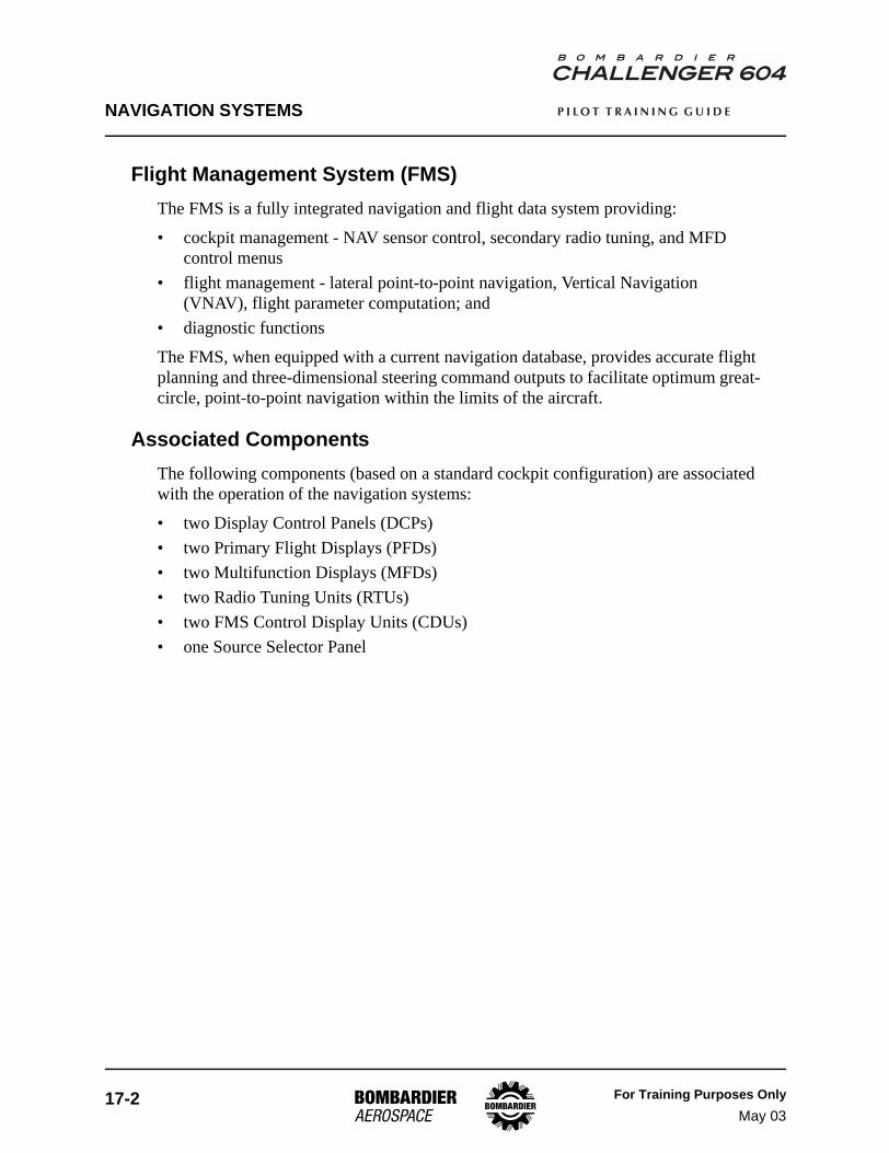
Flight Management System (FMS)The FMS is a fully integrated navigation and flight data system providing:
• cockpit management - NAV sensor control, secondary radio tuning, and MFD control menus
• flight management - lateral point-to-point navigation, Vertical Navigation (VNAV), flight parameter computation; and
• diagnostic functions
The FMS, when equipped with a current navigation database, provides accurate flight planning and three-dimensional steering command outputs to facilitate optimum great-circle, point-to-point navigation within the limits of the aircraft.
Associated ComponentsThe following components (based on a standard cockpit configuration) are associated with the operation of the navigation systems:
• two Display Control Panels (DCPs)• two Primary Flight Displays (PFDs) • two Multifunction Displays (MFDs)• two Radio Tuning Units (RTUs)• two FMS Control Display Units (CDUs)• one Source Selector Panel
NAVIGATION SYSTEMS
For Training Purposes OnlyMay 03
17-3
P I L O T T R A I N I N G G U I D E
Inertial Reference System (IRS)
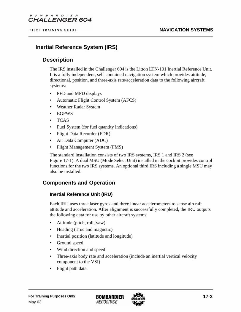
DescriptionThe IRS installed in the Challenger 604 is the Litton LTN-101 Inertial Reference Unit. It is a fully independent, self-contained navigation system which provides attitude, directional, position, and three-axis rate/acceleration data to the following aircraft systems:
• PFD and MFD displays• Automatic Flight Control System (AFCS)• Weather Radar System• EGPWS• TCAS• Fuel System (for fuel quantity indications)• Flight Data Recorder (FDR)• Air Data Computer (ADC)• Flight Management System (FMS)
The standard installation consists of two IRS systems, IRS 1 and IRS 2 (seeFigure 17-1). A dual MSU (Mode Select Unit) installed in the cockpit provides control functions for the two IRS systems. An optional third IRS including a single MSU may also be installed.
Components and Operation
Inertial Reference Unit (IRU)
Each IRU uses three laser gyros and three linear accelerometers to sense aircraft attitude and acceleration. After alignment is successfully completed, the IRU outputs the following data for use by other aircraft systems:
• Attitude (pitch, roll, yaw)• Heading (True and magnetic)• Inertial position (latitude and longitude)• Ground speed• Wind direction and speed• Three-axis body rate and acceleration (include an inertial vertical velocity
component to the VSI)• Flight path data

NAVIGATION SYSTEMS
17-4 For Training Purposes OnlySept 04
P I L O T T R A I N I N G G U I D E
Each IRS receives true airspeed and altitude from the on-side air data system. In the event of a failure of the on-side air data input, the cross-side input is automatically selected.
Power SupplyEach IRU has two power sources, a 115-volt AC source and a backup 28-volt DC source. Either source is sufficient for operation but both are required for initial startup. Inside the IRU, the battery backup circuit automatically switches to the backup 28-volt DC source when the normal 115-volt AC source is not available. During startup, the battery backup circuit verifies that backup power is available by momentarily switching off the 115-volt AC input. The IRS 1(2)(3) ON BATT advisory EICAS message is displayed when an IRU is operating on DC power only.
115-volt, 400-Hz AC power is also supplied to the IRU cooling fans.
Mode Select Unit (MSU)
The mode select unit provides the necessary switches that select the modes of operation of each IRS. All IRS-related annunciations are displayed as EICAS messages or FMS CDU scratchpad messages.
Each MSU switch has three positions: OFF, NAV, and ATT. Power is applied to the IRU whenever the respective switch is selected to the NAV or ATT position.
IRU # AC POWER BACKUP DC POWER
1 AC Essential Bus Battery Bus
2 AC Bus 2 DC Essential BusBattery Bus
3 AC Bus 1 Battery Bus
IRU Power Sources Table 17-1

NAVIGATION SYSTEMS
For Training Purposes OnlyJan 04
17-5
P I L O T T R A I N I N G G U I D E
Figure 17-1 illustrates the dual MSU (for IRS 1 and 2) and the single MSU for the optional third IRU.
Mode Select Unit Figure 17-1
IRS Reversionary Mode Selectors
IRS reversionary mode selector switches are provided to control IRU outputs to the pilot’s and copilot’s PFD and MFD displays. In the event of an IRU failure, the selectors can be used to restore IRU data to the affected side’s displays.
With the reversionary switches at NORM, the PFD and MFD displays normally receive data from their on-side IRS. In a dual-IRS installation, selecting the reversionary selector to 1 or 2 results in both the pilot’s and copilot’s displays receiving information from the selected IRU. In a triple-IRS installation, selecting ALTN replaces the appropriate IRU data with IRU 3 data.
Single-source or cross-side IRS source annunciations are displayed on the affected PFDs (see Figure 17-2).
Figure 17-3 shows the standard reversionary panel and optional reversionary panels based on the indicated avionics configuration.
P6
04
_1
7_
00
2
OFF
NAV
ATT OFF
NAV
ATT
2IRS1
OFF
NAV
ATT
IRS3

NAVIGATION SYSTEMS
17-6 For Training Purposes OnlyJan 04
P I L O T T R A I N I N G G U I D E
PFD IRS Source Annunciations Figure 17-2
1.0
260
220
240
280
20
10
10
30
300
400
500
600
8000
TERMMSG
FMS1
TRU
NO FLIGHT PLAN
TCASOFF
29.85 IN
2400M
GSRA
LNV1LOC 1
DR FLCALTS
FMS1
25DTK 279
.3HOKKE
NM
4
4
2
2
1
1
25
3.6
2500M250
N33
30
W24
63
7
12000
VOR2
P6
04
_1
7_
06
7
IRS SourceAnnunciation
IRS3

NAVIGATION SYSTEMS
For Training Purposes OnlyMay 03
17-7
P I L O T T R A I N I N G G U I D E
Source Selector Panel - IRS Reversionary Mode Selectors Figure 17-3
L IRS
NORM ALTN
R IRS
ALTNNORM
L IRS R IRS FMS3
1 2NORM
1 2NORM ALTN ALTNNORM
TRIPLE IRS INSTALLATION/ TRIPLE FMS
TRIPLE IRS INSTALLATION
DUAL IRS INSTALLATION
P6
04
_1
7_
00
3
PFD EICASNORM
L MFD
1 2
NORMADC
1 2
NORMDCP
EICAS PFDNORM
R MFD
ED1
ED2
NORMEICAS
2
D EIC2
AS PF
21 2
NORMIRS
2
NAVIGATION SYSTEMS
17-8 For Training Purposes OnlyJan 04
P I L O T T R A I N I N G G U I D E
IRS Normal Alignment
Normal alignment is achieved for IRS alignments between ±73° of latitude. When the mode selector switches are in OFF, power is removed from the IRUs. When NAV is selected, power is applied to the IRUs, and the IRUs automatically progress through a self-test mode, followed by an alignment period before navigation (NAV) mode becomes available. The IRU will automatically sequence to NAV mode 7 minutes after the MSU selector switch is turned to NAV if all of the following conditions are met:
• aircraft is on the ground with no excessive motion detected• the gyro temperature is above 0°C• the latitude and position tests have passed• valid IRS initialization data has been received
IRS InitializationIn order to initialize the IRS, the present latitude and longitude coordinates must be entered from either FMS CDU via the POS INIT page. The IRUs remain in the alignment mode with NAV selected on the MSU if the present position is not entered. The initialization data can be changed during the alignment, but both latitude and longitude coordinates must be entered.
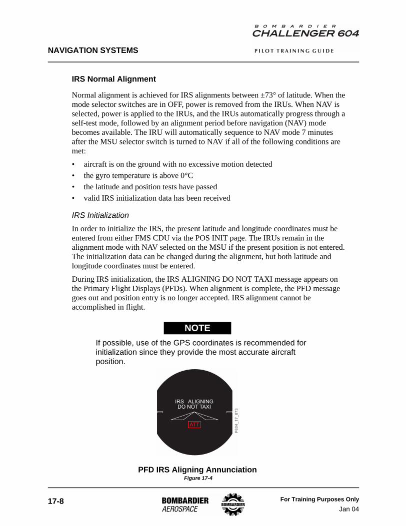
During IRS initialization, the IRS ALIGNING DO NOT TAXI message appears on the Primary Flight Displays (PFDs). When alignment is complete, the PFD message goes out and position entry is no longer accepted. IRS alignment cannot be accomplished in flight.
If possible, use of the GPS coordinates is recommended for initialization since they provide the most accurate aircraft position.
PFD IRS Aligning Annunciation Figure 17-4
NOTE
P6
04
_1
7_
07
3
IRS ALIGNINGDO NOT TAXI
ATT

NAVIGATION SYSTEMS
For Training Purposes OnlyMay 03
17-9
P I L O T T R A I N I N G G U I D E
Low-Temperature AlignmentAt an IRS internal temperature between -54°C and -40°C, the power supply will turn on but normal alignment will not start until the IRS temperature is greater than -40°C. The alignment mode is inhibited when the gyro temperature exceeds +80°C.
The following table shows the time to complete alignment when the gyro temperature is below 0°C. IRU time to complete alignment is displayed on the FMS CDU POS INIT page 3/3.
Alignment time is extended beyond 16 minutes if the gyro temperature has not reached at least -40°C. The system will not go into NAV mode until the gyro temperature reaches -15°C.
Extended 15-Minute AlignmentThe extended 15-minute alignment procedure allows the system to align at latitudes up to 80° north and south.
After NAV has been selected, wait 15 minutes before entering the present position.
Refer to the CL-604 Airplane Flight Manual - Supplement 7, FMS Navigation in Polar Regions, for additional navigation procedures when operating in polar regions.
IRU INTERNAL TEMP(°C)
TIME TO COMPLETE ALIGNMENT (MIN.)
< -12.5 16 (see note)
-12.5 to -10.0 15
-10.0 to -7.5 14
-7.5 to -5.0 13
-5.0 to -2.5 12
-2.5 to 0 11
>0 7
Low-Temperature Alignment Times Table 17-2
NOTE

NAVIGATION SYSTEMS
17-10 For Training Purposes OnlyMay 03
P I L O T T R A I N I N G G U I D E
IRS Rapid Realignment
When the IRS is operating in the NAV mode, it is possible to perform a rapid realignment whenever the aircraft is on the ground. If the MSU selector switch is rotated from NAV to OFF and back to NAV within 5 seconds, the system will sequence into the rapid realignment mode. Velocity components are set to zero, a30-second leveling mode corrects the pitch and roll angles, and no gyro compassing is performed (the last heading from the NAV mode is used). The total rapid realignment sequence takes approximately 32 seconds. Present position must be reentered.
If excessive motion is detected during rapid realignment, the system restarts rapid realignment and resets the time remaining to align to 30 seconds.
IRS Attitude (ATT) Mode
Attitude mode is normally used when an IRS malfunction occurs. It may also be used if all power to the IRS (including battery backup power) is lost then restored during flight. In attitude mode, the IRS provides only pitch, roll, and heading outputs.
Attitude alignment takes 1 minute from power OFF to ATT mode or 34 seconds from NAV to ATT mode, provided the airplane is stationary on the ground or in straight-and-level flight. The IRS ALIGNING DO NOT TAXI message appears on the PFD on ground or IRS ALIGNING message appears in flight.
If excessive motion is detected, the attitude alignment is run for an additional 20 seconds. Once attitude alignment is complete, a free DG heading operation is available. Heading is entered from the FMS CDU IRS CONTROL page via the SET IRS HDG prompt. Heading entries are periodically required while the IRS is in attitude mode to correct for heading drift.
Attitude Mode Figure 17-5
NOTE
P6
04
_1
7_
06
8N33
30
W
3
10
20
DG 340
DG
FMS1 IRS CONTROL
IRS2 <ENABLED>
IRS3 <ENABLED>
<INDEX
- - - °/ - . -
265 °/ 0.0
- - - >
265 °/ 0.0
DRIFT
DRIFT
DRIFT
POS DIFF
- . - NM/HR
- . - NM/HR
- . - NM/HR
SET IRS HDG- - - - - - - - - - - -
[ ]
SET IRS HDG
IRS1 <ENABLED>

NAVIGATION SYSTEMS
For Training Purposes OnlyMay 03
17-11
P I L O T T R A I N I N G G U I D E
IRS Shutdown
The recommended method of shutting down the IRS is by setting the MSU selector switch to OFF. During this shutdown process, the IRU will remain powered for an additional 10 seconds to allow system record storage (aircraft power should not be removed until 15 seconds after the MSU is selected OFF).
To ensure proper system record storage, it is also recommended to keep the IRS in NAV mode for a minimum of three minutes after the aircraft is parked.
Record storage at shutdown consists of the Elapsed Time Indicator (ETI) record update and NAV updates which are required to ensure the best possible alignments and NAV performance. If power is removed from the IRU during the 10-second shutdown, then NAV updates and ETI may not be stored.
Operating Tips
The IRS manufacturer recommends the following operating tips:
PHASE OF FLIGHT RECOMMENDATIONS
Alignment For best performance the IRS should be aligned at random headings. Continuous alignments at or near one cardinal heading may degrade performance.
Initial position entryInitial latitude and longitude should be entered within two minutes of start-up. The initial latitude and longitude position should be within 1 nautical mile of actual aircraft position to ensure the most accurate IRS alignment.
Prior to taxiIt is recommended to remain in NAV mode prior to taxi for at least five minutes. The IRS continues to adjust for bias errors and temperature changes as long as the aircraft is stationary.
Taxi
If practical, it is recommended that the aircraft stops during taxi for a period of one to three minutes with a heading 90 to 180 degrees different than the alignment heading. NAV updates are performed during taxi but will not be used unless the aircraft has stopped for a minimum of one minute.
Intermediate stopsDuring intermediate stops, it is recommended to use the Rapid Realign feature when the IRS remains on during the stop. This will minimize drift errors during subsequent flights as drift error is zeroed.
Post-flightKeep the IRS on for a minimum of three minutes after the aircraft is parked. After the IRS is turned off with the mode select switch, keep the power applied for a minimum of 15 seconds to allow storing of the Nav Update records in the IRS memory.
IRS Operating Tips Table 17-3

NAVIGATION SYSTEMS
17-12 For Training Purposes OnlyMay 03
P I L O T T R A I N I N G G U I D E
Controls and Indicators
IRS Mode Select Unit (MSU) Figure 17-6
IRS Reversionary Mode Selectors (Dual IRS Configuration) Figure 17-7
P6
04
_1
7_
06
9
OFF
NAV
ATT OFF
NAV
ATT
2IRS1
OFF
NAV
ATT
IRS3
IRS 1/2 Mode Selector SwitchesOFFNAVATT
- Removes power from IRS-Selected for normal operation- Selected for reversionary
P6
04
_1
7_
07
0
IRS Reversionary Mode Selector Switch1 - Pilot’s and copilot’s systems receive IRSdata from IRS 1NORM - Pilot’s and copilot’s systems receivedata from their on-side system2 - Pilot’s and copilot’s systems receive IRSdata from IRS 2
PFD EICASNORM
L MFD
1 2
NORMADC
1 2
NORMDCP
EICAS PFDNORM
R MFD
ED1
ED2
NORMEICAS
2
D EIC2
AS PF
21 2
NORMIRS
2

NAVIGATION SYSTEMS
For Training Purposes OnlyJan 04
17-13
P I L O T T R A I N I N G G U I D E
PFD IRS Source Annunciations (Dual IRS Configuration) Figure 17-8
IRS Reversionary Mode Selectors (Triple IRS Configuration) Figure 17-9
EICAS Messages
MESSAGE MEANING
IRS 3 ALIGNING IRS 3 is in align mode or ATT mode with no IRS 3 INOP status message.IRS 1 (2) (3) DC FAIL Indicates the respective IRS DC power supply failed.IRS 1 (2) (3) IN ATT Indicates the respective IRS is operating in attitude mode.IRS 3 INOP Indicates a failure of IRS 3.IRS 1 (2) (3) ON BATT Indicates the respective system is operating on backup battery power.IRS 1 (2) (3) OVERTEMP Indicates an overtemperature condition in the respective IRU.
EICAS Messages Table 17-4
1.0
260
220
240
280
20
10
10
30
300
400
500
600
8000
TERMMSG
FMS1
TRU
NO FLIGHT PLAN
TCASOFF
29.85 IN
2400M
GSRA
LNV1LOC 1
DR FLCALTS
FMS1
25DTK 279
.3HOKKE
NM
4
4
2
2
1
1
25
3.6
2500M250
N33
30
W24
63
7
12000
VOR2
P6
04
_1
7_
07
2
Switch/Position
IRS
1
NORM
2
Pilot’sSide
PFD
—
—
IRS 2
—
—
IRS 1
Copilot’sSide
IRS SourceAnnuciation
IRS2
P6
04
_1
7_
07
1
L IRS Reversionary ModeSelector SwitchNORM
ALTN
- Pilot’s systems receivedata from IRS 1
- Pilot’s systems receive datafrom IRS 3
L IRS R IRS FMS3
1 2NORM
1 2NORM ALTN ALTNNORM
R IRS Reversionary ModeSelector SwitchNORM
ALTN
- Copilot’s systems receivedata from IRS 1
- Copilot’s systems receivedata from IRS 3

NAVIGATION SYSTEMS
17-14 For Training Purposes OnlyMay 03
P I L O T T R A I N I N G G U I D E
Weather Radar System
DescriptionThe weather radar consists of a single unit that detects wet precipitation and precipitation-related turbulence along the flight path of the aircraft. A ground mapping function is incorporated to assist with navigation. An optional Lightning Detection System adds lightning detection to the weather radar displays.
The Radar Transceiver processes weather radar/turbulence data into a digital bus format that may be selected for display on the pilot’s or copilot’s Multifunction Display (MFD).
The baseline weather radar system includes one Weather Radar Control Panel (WXP) that allows selection of various operating modes. An optional second WXP may be installed to provide a split-scan capability. The Display Control Panels (DCPs) control selection of the weather radar overlay and radar range on the MFDs.
NAVIGATION SYSTEMS
For Training Purposes OnlyJan 04
17-15
P I L O T T R A I N I N G G U I D E
Components and Operation
Receiver Transmitter Antenna (RTA)
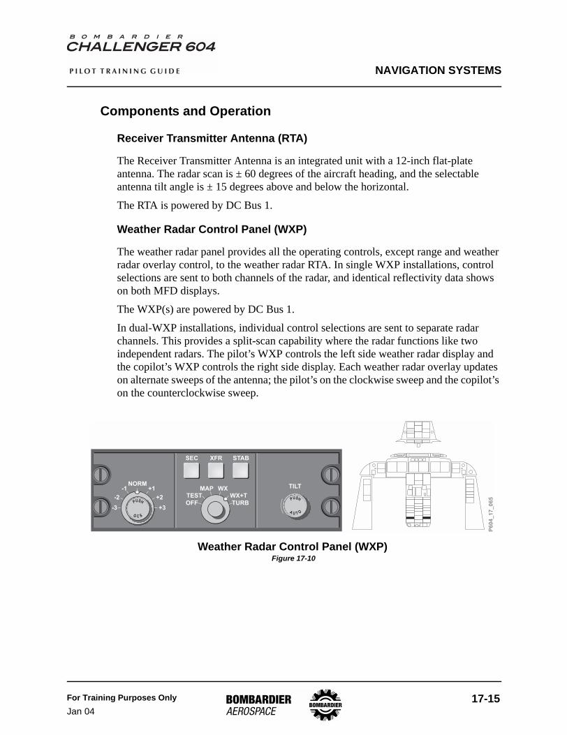
The Receiver Transmitter Antenna is an integrated unit with a 12-inch flat-plate antenna. The radar scan is ± 60 degrees of the aircraft heading, and the selectable antenna tilt angle is ± 15 degrees above and below the horizontal.
The RTA is powered by DC Bus 1.
Weather Radar Control Panel (WXP)
The weather radar panel provides all the operating controls, except range and weather radar overlay control, to the weather radar RTA. In single WXP installations, control selections are sent to both channels of the radar, and identical reflectivity data shows on both MFD displays.
The WXP(s) are powered by DC Bus 1.
In dual-WXP installations, individual control selections are sent to separate radar channels. This provides a split-scan capability where the radar functions like two independent radars. The pilot’s WXP controls the left side weather radar display and the copilot’s WXP controls the right side display. Each weather radar overlay updates on alternate sweeps of the antenna; the pilot’s on the clockwise sweep and the copilot’s on the counterclockwise sweep.
Weather Radar Control Panel (WXP) Figure 17-10
P6
04
_1
7_
06
5NORM
-3
-2
-1 +1
+2
+3OFF
TESTMAP WX
WX+T
TURB
TILT
SEC XFR STAB
PUSH
AU T O
+PUSH
G C S

NAVIGATION SYSTEMS
17-16 For Training Purposes OnlyJan 04
P I L O T T R A I N I N G G U I D E
Mode KnobThe mode knob selects the weather radar operating mode. Available modes are:
• OFF• TEST (test mode)• MAP (ground mapping mode)• WX (weather)• WX+T (weather and turbulence)• TURB (turbulence only)
Annunciation of the selected mode is displayed on the MFD weather radar mode line.
Sector Control (SEC) ButtonPushing the SEC button on the WXP alternatively selects or deselects sector scan mode. When selected, radar scans ± 30 degrees from aircraft heading. When deselected, normal ± 60° scan resumed.
Transfer Control (XFR) ButtonPushing the XFR button on the WXP alternately selects or deselects the transfer function. In single-WXP installations, weather radar range control transfers to the cross-side DCP when the XFR function is selected.
In a dual-WXP installation, operation of the XFR button transfers complete weather radar control to the cross-side WXP and DCP (range, mode, gain and tilt). The cross-side WXP and DCP units control both MFD radar displays. Transfer is allowed on one side only, and the pilot has priority.
When transfer is selected, an “X” annunciates on both MFD radar mode lines and the slaved side line is shown in yellow. The weather radar message RADAR NOT AT THIS RANGE will appear on the slaved side anytime MFD range disagrees with the master side.
Stabilization Control (STAB) ButtonPushing the STAB button on the WXP alternately selects or deselects antenna stabilization. Normally, antenna stabilization is selected to automatically stabilize the radar antenna with attitude input data from the IRS system. This provides a constant antenna scan attitude regardless of the aircraft pitch and roll attitudes.
If antenna stabilization is not selected, attitude input data is removed from the antenna drives. This allows the weather radar system to remain operational if an IRS input failure occurs.
If an IRS failure occurs or if stabilization has been deselected via the STAB button, USTB flashes in cyan for 10 seconds then remains steady, indicating that stabilization

NAVIGATION SYSTEMS
For Training Purposes OnlyJan 04
17-17
P I L O T T R A I N I N G G U I D E
is not available. If an IRS failure occurs, or two WXPs are installed and the cross-side WXP is in control, the annunciation is in yellow.
Tilt ControlThe weather radar antenna tilt arc is 30 degrees above and below the horizon. Fifteen degrees is for manual tilt selection and the remaining 15 degrees is for automatic stabilization. The system automatically adjusts the antenna tilt in response to aircraft pitch and roll attitude changes.
The selected tilt angle (-15° to +15°) is displayed on the weather radar mode line of the MFDs.
Auto-Tilt ControlPushing the PUSH AUTO button in the center of the TILT knob alternately selects or deselects automatic tilt. When selected, the antenna tilt is adjusted to maintain a constant tilt/range ratio as radar range selection is changed. The MFD tilt angle readout is appended by “A” to indicate that automatic tilt is enabled.
The antenna tilt is automatically adjusted when aircraft altitude or radar range is changed. This will keep a ground return at the same relative position on the display. For example, if a ground return was indicated at 40 miles on a 50-mile range setting, it would show at 80 miles (4/5 of the display) if the range setting were changed to 100 miles.
Display Control Panel
WX ButtonPushing the WX button selects the weather radar and/or lightning detection system displays on the MFD. Each push of the WX button sequentially cycles through the following selections:
• WX (weather displayed only)• LX (lightning displayed only)• WX/LX (weather and lightning displayed), then• OFF (removing both from the MFD display)
Display selections are shown on the weather radar mode line of the MFD.
Range KnobThe range knob on the DCP is used to set the display range. The outer range ring of the MFD is numbered with the selected range. The middle range ring indicates half the selected range. The available ranges are 5, 10, 25, 50, 100, 200 and 300 NM when weather radar is in use.

NAVIGATION SYSTEMS
17-18 For Training Purposes OnlyJan 04
P I L O T T R A I N I N G G U I D E
In a dual-WXP installation, weather radar range and weather radar overlay selections are controlled individually on each the DCP. The applicable range selection is shown on each MFD.
In a single-WXP installation, radar range is controlled with the DCP located on the same side of the cockpit as the WXP, providing transfer mode is not selected (XFR button on the DCP).
Display Control Panel (DCP) Figure 17-11
Weather Radar Displays
Pushing the WX button on the DCP adds the weather radar overlay to the following MFD formats:
• NAV SECTOR• FMS MAP• TCAS
Figure 17-14 shows an example of the weather radar overlay on the supported MFD formats.
Weather radar system and/or lightning detection system failure messages are displayed on the weather radar mode line, or in the lower left and right corners of the MFDs.
NAVSOURCE
FORMAT RANGE
BRG TERR WX TFC
PUSH
X- S I D
E
P6
04
_1
7_
05
7

NAVIGATION SYSTEMS
For Training Purposes OnlyMay 03
17-19
P I L O T T R A I N I N G G U I D E
MFD Formats - Display of Weather Radar Figure 17-12
WX G+3 USTB T+10.7
TAS TATUTC11:42 250 SAT 12 C 15 C
+02
-02
-10
TCAS OFFABOVEBELOW
TCAS MODE
�
�
10NM
GS 254
CID
30
33 340N
3
100
ADF 1 ADF 2
200
WX+GCS T+10.7ATAS TATUTC11:42 250 GS 254 SAT 12 C 15 C
VOR1CIDTTG :07
CRS 35030.0NM
VOR2DBQ
CRS 030167NM
TTG :38
NAV SECTOR MODE
IA
IOW
ATY
MXOANOSA
DBQ
OTM
NEBOR
TNU
ALO
30
33 340N
3
50
100
LX/WX+TRB+GCS G+3
G+3
USTB
USTB
T+10.7
UTC TAS GS TAT11:42 250 254 SAT 12 C -15 C
ADF 1 ADF 2
DBQCID
ATYKORD
NM45NM
83NM480NM
042 0:100:201:57
11:5211:32
12:0213:39 8440LB 35.3GW
DataWindow
FMS MAP MODE
P6
04
_1
7_
01
0
Weather RadarMode Line

NAVIGATION SYSTEMS
17-20 For Training Purposes OnlyJan 04
P I L O T T R A I N I N G G U I D E
Display LevelsThe colors used on the radar display to represent rainfall intensity are as follows:
Path Attenuation Correction (PAC) Alert ModeWhen a precipitation cell is of sufficient dimension to use the full range of attenuation correction, a condition known as Path Attenuation Correction (PAC) alert occurs. Its function is to allow a true image of a precipitation cell to be rendered by making allowances for the radar beam’s absorption as it penetrates the precipitation cell. The PAC alert puts into view those areas which absorb the radar beam.
The heading to these areas is shown by a yellow arc at the edge of the radar display. All precipitation in the sector between the displayed weather targets and the yellow PAC alert arc may be incorrect and should be avoided.
DISPLAY LEVEL RAINFALL RATE (MM/HR) RAINFALL RATE (INCHES/HR)
6 (magenta) Turbulence Turbulence
5 (yellow) PAC (path attenuation correction) PAC (path attenuation correction)
4 (magenta)Intense > 51 > 2.0
3 (red)Strong > 12.7 - 51 > 0.5 - 2.0
2 (yellow)Moderate > 3.8 - 12.7 > 0.15 - 0.5
1 (green)Weak > 0.76 - 3.8 > 0.03 - 0.15
0 (black) > 0.15 - 0.76 > 0.006 - 0.03
Weather Radar Display Levels Table 17-5
NAVIGATION SYSTEMS
For Training Purposes OnlyMay 03
17-21
P I L O T T R A I N I N G G U I D E
Weather Radar Display Modes
Refer to the “Collins Pro Line 4 Avionics System for the Challenger 604” Pilot’s Guide for additional operational information on the weather radar system.
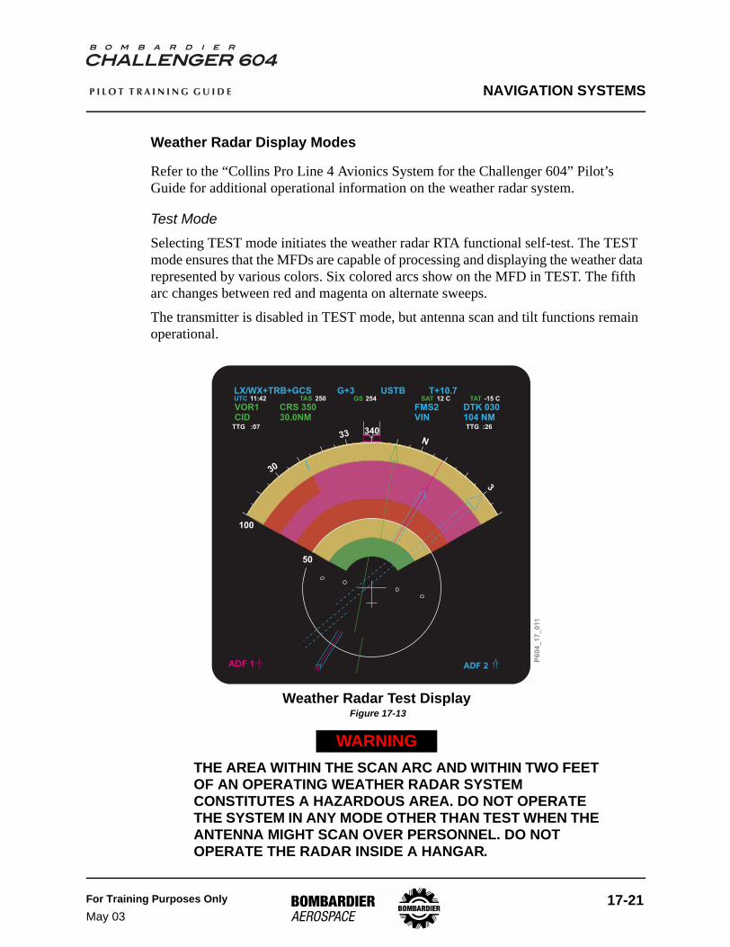
Test ModeSelecting TEST mode initiates the weather radar RTA functional self-test. The TEST mode ensures that the MFDs are capable of processing and displaying the weather data represented by various colors. Six colored arcs show on the MFD in TEST. The fifth arc changes between red and magenta on alternate sweeps.
The transmitter is disabled in TEST mode, but antenna scan and tilt functions remain operational.
Weather Radar Test Display Figure 17-13
THE AREA WITHIN THE SCAN ARC AND WITHIN TWO FEET OF AN OPERATING WEATHER RADAR SYSTEM CONSTITUTES A HAZARDOUS AREA. DO NOT OPERATE THE SYSTEM IN ANY MODE OTHER THAN TEST WHEN THE ANTENNA MIGHT SCAN OVER PERSONNEL. DO NOT OPERATE THE RADAR INSIDE A HANGAR.
WARNING
30
33 340N
3
50
ADF 1 ADF 2
100
LX/WX+TRB+GCS G+3 USTB T+10.7UTC TAS GS TAT11:42 250 254 SAT 12 C -15 C
VOR1CID
CRS 35030.0NM
FMS2VIN
DTK 030104 NMTTG :26TTG :07
P6
04
_1
7_
011

NAVIGATION SYSTEMS
17-22 For Training Purposes OnlyMay 03
P I L O T T R A I N I N G G U I D E
Weather Only (WX) ModeDetectable weather appears as one of four colors: green, yellow, red, or magenta. The highest precipitation rates are represented in magenta.
Weather Plus Turbulence (WX+T) ModeWeather plus turbulence adds the detection of precipitation-related turbulence targets to the weather mode. The highest precipitation rates and turbulence show in magenta.
WX+T is operational for ranges less than or equal to 40 NM. When ranges greater than 50 NM are selected in WX+T mode, the weather radar reverts to the WX mode.
Turbulence Only (TURB) ModeThe TURB mode on the WXP is a spring-loaded position. Selecting TURB mode removes all targets except detected precipitation-related turbulence within the 50 NM range. TURB mode is useful in analyzing areas of precipitation-related turbulence that have been detected while in the WX+T mode. By removing all weather returns from the display, the areas of turbulence (magenta) can be observed alone.
Lightning Detection System (Optional)
The lightning detection system maps electrical discharge activity (lightning) 360 degrees around the aircraft to a distance of 200 nautical miles. Three levels of electrical activity intensity are identified. Level one represents the lowest rate of electrical discharge and level three the highest.
The system transmits the location of up to 63 thunderstorm cells to the MFDs. The data set is updated every two seconds. Electrical discharge activity is presented as thunderbolts on the MFD in yellow, red, and magenta, with yellow signifying level one, and magenta signifying level three activity.
The lightning detection system is selected by the WX button on the Display Control Panel (DCP).

NAVIGATION SYSTEMS
For Training Purposes OnlyJan 04
17-23
P I L O T T R A I N I N G G U I D E
Controls and Indicators
Weather Radar Control Panel (WXP) Figure 17-14
NORM
-3
-2
-1 +1
+2
+3OFF
TESTMAP WX
WX+T
TURB
TILT
SEC XFR STAB
PUSH
AU T O
+PUSH
G C S
Transfer SwitchTransfers control of WX radar displayrange to pilot's or copilot's displaycontrol panel.
Sector Scan SwitchWhen pressed in, multifunctiondisplay indicates azimuth angle of±30° on either side of flight path.Not pressed, multifunction displayindicates azimuth angle of ±60° oneither side of flight path.
Receiver Gain Switch
-1, -2, -3 positions
+1, +2, +3 positions
Controls receiver gain in mapand WX modes
- Reducesensitivity
- Increasesensitivity
Stabilization Select SwitchNormally, antenna stabilized by IRSsystem. No MFD indication. Duringan airplane attitude system failure(USTB flashing), when pressed, MFDdisplays USTB.
Ground Clutter Suppression (GCS)SwitchWhen pressed in during WX mode,reduces the intensity of groundreturns and permits clearer definitionof precipitation. Clutter suppressionlasts approximately 12 seconds.When selected, GCS is displayed onMFD. Any mode or range changecancels GCS.
Mode Select Switch
OFF
TEST
MAP
WX
Mode selections indicated at top of MFD. Modes are:- Removes power to weather radar receiver/
transmitter/antenna unit. WX off mode displayed on MFD.- Starts weather self-test program, and test pattern
indicated on MFD, test mode displayed on MFD.- Ground targets displayed in cyan, green, yellow, or
magenta (least to most reflective) on MFD. Map modedisplayed on MFD.
- Detectable weather displayed in green, yellow, red, ormagenta, from least reflective to most reflective. PACcompensation and alerts enable. WX mode displayed onMFD.WX+T
TURB
– Enables the RTA to detect both weather andturbulence targets
– Enables the RTA to detect turbulence targets. TheMFD displays only the detected areas of turbulence when inthe TURB mode.
Tilt Control SwitchRotate to change antenna tilt up ordown angle for desired radarscanning. Multifunction display (MFD)indicates tilt angle selected. Tilt limitsare from 15° up to 15° down.
Auto-tilt Correction SwitchPush to select or deselect antennaauto-tilt. Multifunction displayindicates auto-tilt selected as an "A"suffixed to the tilt angle (T + 10.7A)
P6
04
_1
7_
00
7

NAVIGATION SYSTEMS
17-24 For Training Purposes OnlyMay 03
P I L O T T R A I N I N G G U I D E
Display Control Panel (Weather Radar Functions) Figure 17-15
Radar Mode Selection
Current Format MFD Format After WX Press
HSI . . . . . . . . . . . . . . . . . . . . . . . . . FMS MAP + RADARPLAN MAP. . . . . . . . . . . . . . . . . . . FMS MAP + RADAR
FMS MAP. . . . . . . . . . . . . . . . . . . . FMS MAP + RADARFMS MAP + RADAR . . . . . . . . . . . FMS MAP + RADAR + LXFMS MAP + RADAR + LX . . . . . . . FMS MAP
NAV SECTOR . . . . . . . . . . . . . . . . NAV SECTOR + RADARNAV SECTOR + RADAR . . . . . . . . NAV SECTOR + RADAR + LXNAV SECTOR + RADAR + LX. . . . NAV SECTOR
TCAS . . . . . . . . . . . . . . . . . . . . . . . TCAS + RADARTCAS + RADAR. . . . . . . . . . . . . . . TCAS + RADAR + LXTCAS + RADAR + LX . . . . . . . . . . TCAS
NAVSOURCE
FORMAT RANGE
BRG TERR WX TFC
PUSH
X- S I D
E
FORMAT
Modes
Format menu has “electronic stops”at HSI (always available), and at itsmost clockwise available selection.The modes are shown below in theorder that they are available on theknob from the furthestcounterclockwise to the furthestclockwise:
- HSI- NAV SECTOR- FMS MAP- PLAN MAP- TCAS
RANGERange values are listed in the orderthat they occur from the mostclockwise positions of the rangeknob (there are “electronic stops” atboth ends of the range knobs).
(MAP andRADAR Modes)5, 10, 25, 50, 100, 200, 300
Standard RANGE Menu:
TFC SwitchSelects TCAS fordisplay on the MFD
P6
04
_1
7_
00
9
NAVIGATION SYSTEMS
For Training Purposes OnlyJan 04
17-25
P I L O T T R A I N I N G G U I D E
Weather Radar Display Figure 17-16
ADF1 ADF2
UTC11 : 42
TTG : 0711
VOR1CID
CRS 350 FMS2 DTK 333
TAS GS SAT250 254 12C TAT–15CTGT
YUL30.0NM 12.7NMTTG11 : 04
50
100
340
LX/WX+TRB+GCS T+10.7G+3 USTB
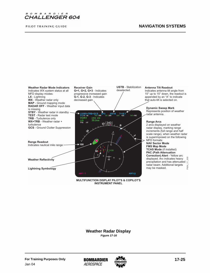
Weather Radar Mode Indicators
LXWXMAPRADAR OFF
STBYTESTTRBWX+TRB
GCS
Indicates WX system status at allMFD display modes:
- Lightning- Weather radar only
- Ground mapping mode- Weather input data
is missing- Weather radar in standby- Radar test mode
- Turbulence only- Weather radar +
turbulence- Ground Clutter Suppression
Range ReadoutIndicates nautical mile range
Receiver GainG+1, G+2, G+3
G-1, G-2, G-3
- Indicatesprogressive increased gain
- Indicatesdecreased gain
Antenna Tilt ReadoutIndicates antenna tilt angle from15° up to 15° down, the readout isappended by an “A” to indicatethat auto-tilt is selected on.
Range Arcs
NAV Sector ModeFMS Map ModeTCAS ModePAC (Path AttenuationCorrection) Alert
2 arcs displayed on weatherradar display, marking rangeincrements (full range and halfscale range), when weather radaris superimposed on the followingMFD formats:
(if installed)
- Yellow arcdisplayed. Arc indicates heavyprecipitation and has attenuatedradar beam. Additional targetsmay be masked.
Dynamic Sweep MarkRepresents position of weatherradar antenna.
USTB - Stabilizationdeselected.
MULTIFUNCTION DISPLAY PILOT'S & COPILOT'SINSTRUMENT PANEL
Weather Reflectivity
CID
Lightning Symbology P6
04
_1
7_
00
8

NAVIGATION SYSTEMS
17-26 For Training Purposes OnlyMay 03
P I L O T T R A I N I N G G U I D E
Weather Radar/Lightning Detection System MessagesWeather radar system and/or lightning detection system failure messages are displayed on the MFD as shown below:
WXR RANGE/CONTROL FAULT ANNUNCIATION DESCRIPTION
RADAR CONTROL FAULT Range received from the weather radar system disagrees with the range received from the DCP.
RDR NOT AT THIS RANGERDR NOT AT TCAS RANGE
Control is transferred and the range received from the weather radar system disagrees with the range received from the DCP.
WXR Range/Control Fault Annunciation Table 17-6
LX/WX FAULT ANNUNCIATION DESCRIPTION
WX FAULT Weather radar system detects an internal fault.
LX FAULT Lightning Detection System detects an internal fault or the MFD detects invalid data.
LX/WX FAULT Weather radar system detects an internal fault and Lightning Detection System detects an internal fault or the MFD detects invalid data.
Lightning/Weather Fault Annunciation Table 17-7

NAVIGATION SYSTEMS
For Training Purposes OnlyJan 04
17-27
P I L O T T R A I N I N G G U I D E
Pilot and Copilot MFD - Weather Radar Fault Annunciation Figure 17-17
ADF1 ADF2
UTC11 : 42
TTG : 0711
VOR1CID
CRS 350 FMS2 DTK 333
TAS GS SAT250 254 12C TAT–15CTGT
YUL30.0NM 12.7NMTTG11 : 04
50
100
340
LX/WX+TRB+GCS T+10.7G+3 USTB
CID
LX/WX FAULTRADAR NOT AT TCAS RANGERADAR NOT AT THIS RANGE
RADAR CONTROL FAULT
WXR Range/ControlFault Annunciation
LX/WX FaultAnnunciation
P6
04
_1
7_
01
2

NAVIGATION SYSTEMS
17-28 For Training Purposes OnlyMay 03
P I L O T T R A I N I N G G U I D E
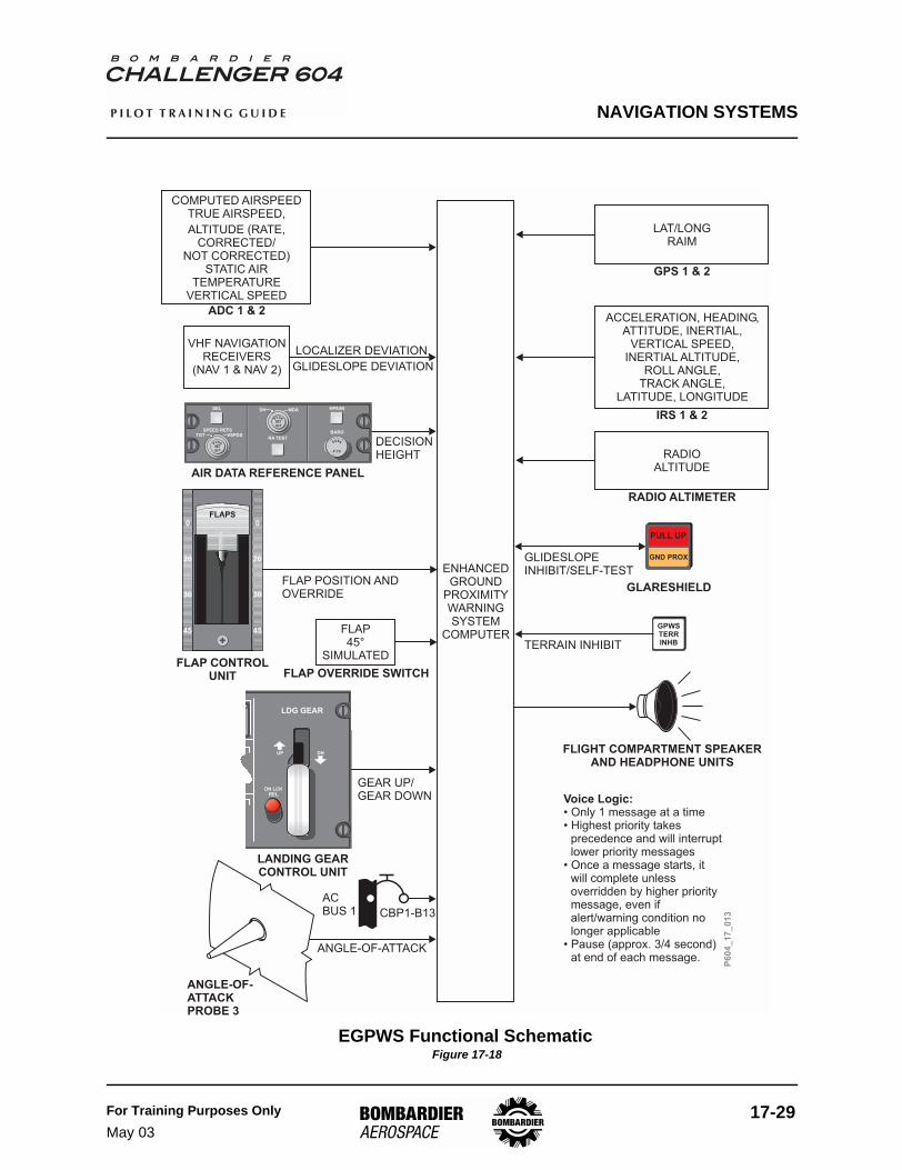
Enhanced Ground Proximity Warning System (EGPWS)
DescriptionThe EGPWS alerts and warns the flight crew when the airplane’s flight path and position relative to terrain requires immediate crew attention and action. EGPWS alerts the flight crew when predetermined thresholds are exceeded using the following modes:
• Mode 1 - Excessive Descent Rate• Mode 2 - Excessive Terrain Closure Rate• Mode 3 - Altitude Loss after Takeoff or Go-Around• Mode 4 - Unsafe Terrain Clearance when not in a Landing Configuration• Mode 5 - Below Glideslope Deviation Alert• Mode 6- Callouts• Mode 7 - Windshear Detection and Alerting• Terrain/Obstacle Awareness Alerting and Display (TAAD)• Terrain Clearance Floor (TCF)
Modes 1 through 6 are installed in all aircraft (basic GPWS). Mode 7, TAAD, and TCF are installed in the aircraft equipped with “Enhanced” GPWS. Consult your Airplane Flight Manual supplement for individual aircraft installation.
NAVIGATION SYSTEMS
For Training Purposes OnlyMay 03
17-29
P I L O T T R A I N I N G G U I D E
EGPWS Functional Schematic Figure 17-18
ENHANCEDGROUND
PROXIMITYWARNINGSYSTEM
COMPUTER
FLIGHT COMPARTMENT SPEAKERAND HEADPHONE UNITS
Voice Logic:• Only 1 message at a time• Highest priority takes
precedence and will interruptlower priority messages
• Once a message starts, itwill complete unlessoverridden by higher prioritymessage, even ifalert/warning condition nolonger applicable
• Pause (approx. 3/4 second)at end of each message.
GLARESHIELD
RADIOALTITUDE
ACCELERATION, HEADING,ATTITUDE, INERTIAL,
VERTICAL SPEED,INERTIAL ALTITUDE,
ROLL ANGLE,TRACK ANGLE,
LATITUDE, LONGITUDE
GLIDESLOPEINHIBIT/SELF-TEST
COMPUTED AIRSPEEDTRUE AIRSPEED,
ALTITUDE (RATE,CORRECTED/
NOT CORRECTED)STATIC AIR
TEMPERATUREVERTICAL SPEED
VHF NAVIGATIONRECEIVERS
(NAV 1 & NAV 2)
LOCALIZER DEVIATION,
GLIDESLOPE DEVIATION
AIR DATA REFERENCE PANEL
DECISIONHEIGHT
FLAP CONTROLUNIT
FLAP POSITION ANDOVERRIDE
GEAR UP/GEAR DOWN
LANDING GEARCONTROL UNIT
ACBUS 1 CBP1-B13
ANGLE-OF-ATTACKPROBE 3
ANGLE-OF-ATTACK
ADC 1 & 2
IRS 1 & 2
RADIO ALTIMETER
FLAP45°
SIMULATED
FLAP OVERRIDE SWITCH
P604_17_013
P
USH
SET
O F F
SEL
SPEED REFSTGT VSPDS
BARO
HPA/INDH MDA
RA TEST
P
USH
SET
O F F
PUSH
ST D
0
20
30
45
0
20
30
45
FLAPS
LAT/LONGRAIM
GPS 1 & 2
UP DN
LDG GEAR
DN LCKREL
PULL UP
GND PROX
GPWSTERRINHBTERRAIN INHIBIT

NAVIGATION SYSTEMS
17-30 For Training Purposes OnlyMay 03
P I L O T T R A I N I N G G U I D E
Components and OperationEGPWS Computer (EGPWC)The EGPWC receives inputs from the air data system, radio altimeters, VHF Nav receivers, GPS, IRS, Angle-of-Attack vanes, gear and flap selector levers and glareshield switch/lights. These inputs are used to compute potential terrain conflicts.
Mode 1 - Excessive Descent Rate
Mode 1 provides aural and visual alerts and warnings in the event that the EGPWC determines that the rate of descent is excessive with respect to airplane altitude. The mode is active when the airplane is less than 2500 feet AGL. Mode 1 requires radio altitude and rate of descent data.
The annunciation envelope consists of two areas: alert and warning.
• penetration of the alert area will illuminate the GND PROX switch/lights on the glareshield and generate an aural “SINKRATE SINKRATE”. The aural alert will be annunciated once, and will be repeated only if condition degrades by more than 20% based on computed time to impact. The visual alert will remain until the condition is rectified
• penetration of the warning area will illuminate the PULL UP switch/lights on the glareshield and generate an aural “WHOOP, WHOOP, PULL UP” warning. The aural warning is annunciated continuously until the condition is rectified
EGPWS Mode 1 Figure 17-19
P6
04
_1
7_
01
4
2500
2000
1500
1000
500
00 2000 4000 6000 8000
"PULL
UP""S
INKRATE
”
RA
DIO
ALT
ITU
DE
(FE
ET
)
DESCENT RATE (FEET/MINUTE)
“SINKRATE”
“PULL UP”

NAVIGATION SYSTEMS
For Training Purposes OnlyMay 03
17-31
P I L O T T R A I N I N G G U I D E
Mode 2 - Excessive Terrain Closure Rate
Mode 2 provides alerts and warnings when the EGPWC detects that the closure rate between the airplane and terrain is excessive. The airplane need not be in descent, rising terrain may be encountered in level flight, or the terrain may be rising at a rate greater than the airplane rate of climb. Mode 2 uses radio altitude, vertical speed and aircraft configuration inputs.
Mode 2 has two submodes: Mode 2A and Mode 2B.
• Mode 2A - Activated when flaps are not in the landing position and the aircraft is not in the GS beam. Penetration of the alert area will illuminate the GND PROX switch/lights on the glareshield and generate an aural “TERRAIN, TERRAIN”. The aural is annunciated once, and the visual alert will remain displayed, until the condition is rectified. Penetration of the warning area will illuminate the PULL UP switch/lights on the glareshield and generate an aural “PULL UP” warning. The aural and visual warnings are annunciated continuously until the condition is rectified
EGPWS Mode 2A Figure 17-20
P6
04
_1
7_
01
5
2500
2000
1500
1000
500
00 2000 4000 6000 8000
RA
DIO
ALT
ITU
DE
(FE
ET
)
TERRAIN CLOSURE RATE (FEET/MIN)
“TERRAINTERRAIN”
“PULL UP”
"PULL UP"
“T
ER
RA
INT
ER
RA
IN”

NAVIGATION SYSTEMS
17-32 For Training Purposes OnlyMay 03
P I L O T T R A I N I N G G U I D E
• Mode 2B - Activated when flaps are in the landing configuration, or in the event the flaps are up and the airplane is on an ILS approach and the glideslope and localizer deviations are less than ±2 dots and for 60 seconds after takeoff. Penetration of the alert area will illuminate the GND PROX switch/lights on the glareshield and enable an aural “TERRAIN, TERRAIN”. The aural and the visual alerts are annunciated continuously and will remain until the condition is rectified. Penetration of the warning area will illuminate the PULL UP switch/lights on the glareshield and generate an aural “PULL UP” warning. The aural and visual warnings are annunciated continuously until the condition is rectified
EGPWS Mode 2B Figure 17-21
P6
04
_1
7_
01
6
2500
2000
1500
1000
500
00 2000 4000 6000 8000
RA
DIO
ALT
ITU
DE
(FE
ET
)
TERRAIN CLOSURE RATE (FEET/MIN)
“TERRAINTERRAIN” “PULL UP”
“PULL UP”
“TERRAIN TERRAIN”

NAVIGATION SYSTEMS
For Training Purposes OnlyMay 03
17-33
P I L O T T R A I N I N G G U I D E
Mode 3 - Altitude Loss after Takeoff
Mode 3 provides warnings when the EGPWC detects that a significant amount of altitude is lost immediately after takeoff or during a go-around. Mode 3 uses radio altitude, barometric altitude and altitude rate.
If a descent is initiated following takeoff or go-around, the EGPWC stores the altitude value at which the descent began, and compares successive altitude data to the stored value. Activation of the warning is induced when the minimum terrain clearance, as a function of altitude lost, is exceeded.
Penetration of the alert area will illuminate the GND PROX switch/lights on the glareshield and generate an aural “DON’T SINK, DON’T SINK” warning. The aural warning is annunciated only once, unless the altitude value degrades by more than 20% from the initially stored value, and again at each additional 20% degradation from the initially stored value. This condition will remain until the airplane regains the initial altitude value. Mode 3 is inhibited for radio altitude in excess of 1500 feet.
EGPWS Mode 3
P6
04
_1
7_
01
7
2500
2000
1500
1000
500
00 150 300
RA
DIO
ALT
ITU
DE
(FE
ET
)
ALTITUDE LOSS (FEET)
“DON'T SINK”
“DON'T SINK”
10050 200 250
NAVIGATION SYSTEMS
17-34 For Training Purposes OnlyMay 03
P I L O T T R A I N I N G G U I D E
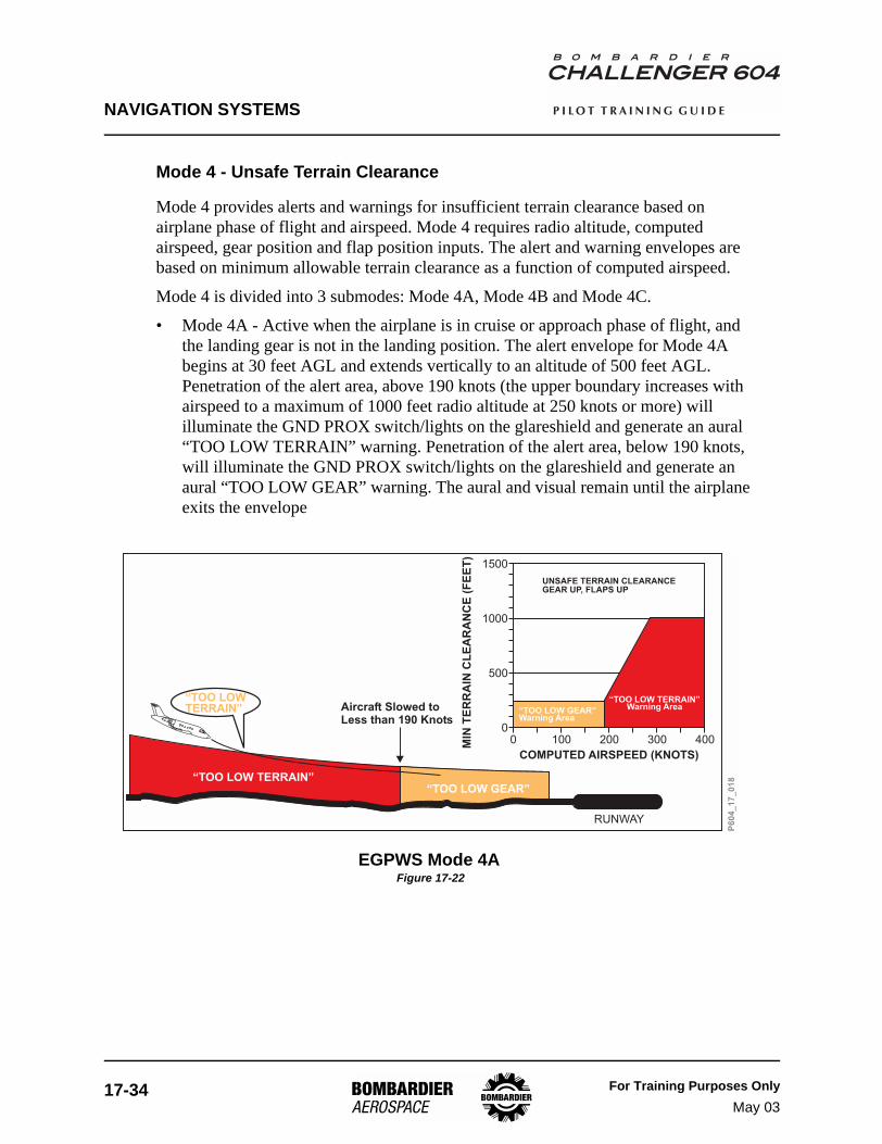
Mode 4 - Unsafe Terrain Clearance
Mode 4 provides alerts and warnings for insufficient terrain clearance based on airplane phase of flight and airspeed. Mode 4 requires radio altitude, computed airspeed, gear position and flap position inputs. The alert and warning envelopes are based on minimum allowable terrain clearance as a function of computed airspeed.
Mode 4 is divided into 3 submodes: Mode 4A, Mode 4B and Mode 4C.
• Mode 4A - Active when the airplane is in cruise or approach phase of flight, and the landing gear is not in the landing position. The alert envelope for Mode 4A begins at 30 feet AGL and extends vertically to an altitude of 500 feet AGL. Penetration of the alert area, above 190 knots (the upper boundary increases with airspeed to a maximum of 1000 feet radio altitude at 250 knots or more) will illuminate the GND PROX switch/lights on the glareshield and generate an aural “TOO LOW TERRAIN” warning. Penetration of the alert area, below 190 knots, will illuminate the GND PROX switch/lights on the glareshield and generate an aural “TOO LOW GEAR” warning. The aural and visual remain until the airplane exits the envelope
EGPWS Mode 4A Figure 17-22
P6
04
_1
7_
01
8
1500
1000
500
00 100 200 300 400
“TOO LOWTERRAIN”
“TOO LOW TERRAIN”“TOO LOW GEAR”
Aircraft Slowed toLess than 190 Knots
MIN
TE
RR
AIN
CL
EA
RA
NC
E(F
EE
T)
COMPUTED AIRSPEED (KNOTS)
RUNWAY
UNSAFE TERRAIN CLEARANCEGEAR UP, FLAPS UP
“TOO LOW GEAR”Warning Area
“TOO LOW TERRAIN”Warning Area

NAVIGATION SYSTEMS
For Training Purposes OnlyMay 03
17-35
P I L O T T R A I N I N G G U I D E
• Mode 4B - Active when the airplane is in cruise or approach phase of flight, and the landing gear is in the landing position and flaps are not in the landing configuration. The alert envelope for Mode 4B extends vertically to an altitude of 245 feet AGL. Penetration of the alert area, above 159 knots, will illuminate the GND PROX switch/lights on the glareshield and generate a continuous aural “TOO LOW TERRAIN” warning. The aural and visual warning remains until the airplane exits the envelope. Penetration of the alert area, below 159 knots, will illuminate the GND PROX switch/lights on the glareshield and generate an aural “TOO LOW FLAP” warning. These alerts can be deactivated by selecting the GPWS FLAP OVRD switch to override
EGPWS Mode 4B Figure 17-23
P6
04
_1
7_
01
9
1500
1000
500
00 100 200 300 400
“TOO LOWTERRAIN”
“TOO LOW TERRAIN”“TOO LOW FLAPS”
Aircraft Slowed toLess than 159 KnotsGear Down
MIN
TE
RR
AIN
CL
EA
RA
NC
E(F
EE
T)
COMPUTED AIRSPEED (KNOTS)
RUNWAY
Unsafe terrain clearancegear down, flaps <30
“TOO LOW TERRAIN”Warning Area
“TOO LOW FLAPS”Warning Area
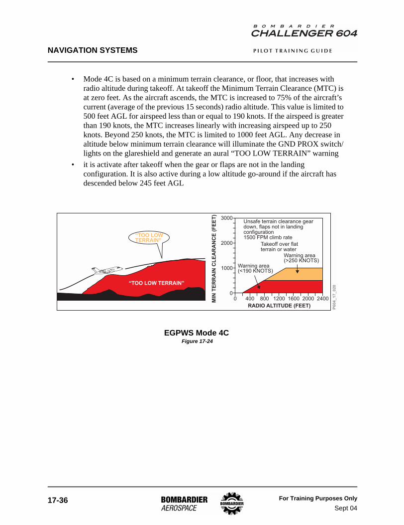
NAVIGATION SYSTEMS
17-36 For Training Purposes OnlySept 04
P I L O T T R A I N I N G G U I D E
• Mode 4C is based on a minimum terrain clearance, or floor, that increases with radio altitude during takeoff. At takeoff the Minimum Terrain Clearance (MTC) is at zero feet. As the aircraft ascends, the MTC is increased to 75% of the aircraft’s current (average of the previous 15 seconds) radio altitude. This value is limited to 500 feet AGL for airspeed less than or equal to 190 knots. If the airspeed is greater than 190 knots, the MTC increases linearly with increasing airspeed up to 250 knots. Beyond 250 knots, the MTC is limited to 1000 feet AGL. Any decrease in altitude below minimum terrain clearance will illuminate the GND PROX switch/lights on the glareshield and generate an aural “TOO LOW TERRAIN” warning
• it is activate after takeoff when the gear or flaps are not in the landing configuration. It is also active during a low altitude go-around if the aircraft has descended below 245 feet AGL
EGPWS Mode 4C Figure 17-24
P6
04
_1
7_
02
0
3000
2000
1000
00 400 800 1200 1600 2000 2400
“TOO LOWTERRAIN”
MIN
TE
RR
AIN
CL
EA
RA
NC
E(F
EE
T)
RADIO ALTITUDE (FEET)
“TOO LOW TERRAIN”
Warning area(<190 KNOTS)
Warning area(>250 KNOTS)
Unsafe terrain clearance geardown, flaps not in landingconfiguration1500 FPM climb rate
Takeoff over flatterrain or water
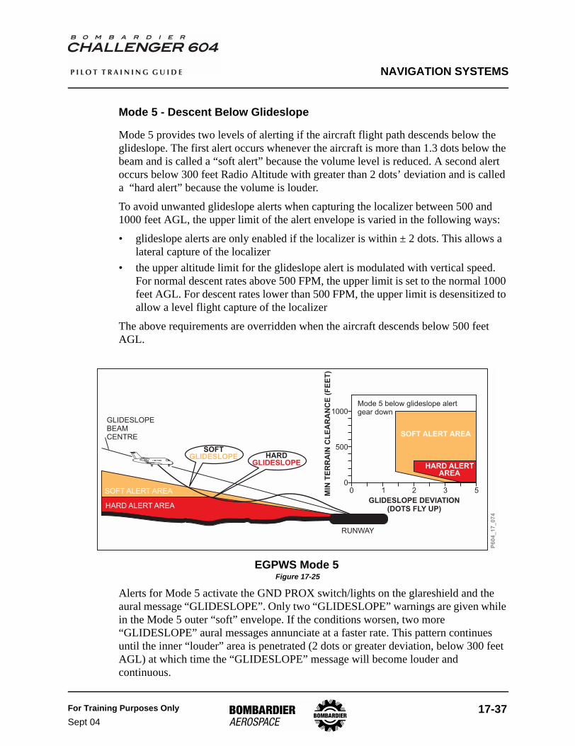
NAVIGATION SYSTEMS
For Training Purposes OnlySept 04
17-37
P I L O T T R A I N I N G G U I D E
Mode 5 - Descent Below Glideslope
Mode 5 provides two levels of alerting if the aircraft flight path descends below the glideslope. The first alert occurs whenever the aircraft is more than 1.3 dots below the beam and is called a “soft alert” because the volume level is reduced. A second alert occurs below 300 feet Radio Altitude with greater than 2 dots’ deviation and is called a “hard alert” because the volume is louder.
To avoid unwanted glideslope alerts when capturing the localizer between 500 and 1000 feet AGL, the upper limit of the alert envelope is varied in the following ways:
• glideslope alerts are only enabled if the localizer is within ± 2 dots. This allows a lateral capture of the localizer
• the upper altitude limit for the glideslope alert is modulated with vertical speed. For normal descent rates above 500 FPM, the upper limit is set to the normal 1000 feet AGL. For descent rates lower than 500 FPM, the upper limit is desensitized to allow a level flight capture of the localizer
The above requirements are overridden when the aircraft descends below 500 feet AGL.
EGPWS Mode 5 Figure 17-25
Alerts for Mode 5 activate the GND PROX switch/lights on the glareshield and the aural message “GLIDESLOPE”. Only two “GLIDESLOPE” warnings are given while in the Mode 5 outer “soft” envelope. If the conditions worsen, two more “GLIDESLOPE” aural messages annunciate at a faster rate. This pattern continues until the inner “louder” area is penetrated (2 dots or greater deviation, below 300 feet AGL) at which time the “GLIDESLOPE” message will become louder and continuous.
P6
04
_1
7_
07
4
1000
500
00 1 2 3 5
SOFTGLIDESLOPE HARD
GLIDESLOPE
MIN
TE
RR
AIN
CL
EA
RA
NC
E(F
EE
T)
GLIDESLOPE DEVIATION(DOTS FLY UP)
Mode 5 below glideslope alertgear down
SOFT ALERT AREA
HARD ALERTAREA
RUNWAY
GLIDESLOPEBEAMCENTRE
SOFT ALERT AREA
HARD ALERT AREA

NAVIGATION SYSTEMS
17-38 For Training Purposes OnlySept 04
P I L O T T R A I N I N G G U I D E
Below 150 feet AGL, glideslope alerting is desensitized to reduce the possibility of nuisance alerts.
To permit maneuvering on final approach with an unreliable glideslope, the Mode 5 alert can be inhibited by pressing the GND PROX/PULL UP switch/light on either side of the glareshield. The GND PROX/PULL UP switch/light can be engaged below 2000 feet AGL and is automatically reset before the next approach, provided the aircraft has descended below 30 feet or climbs above 2000 feet.

NAVIGATION SYSTEMS
For Training Purposes OnlyMay 03
17-39
P I L O T T R A I N I N G G U I D E
Mode 6 - Callouts
Mode 6 provides the following advisory alerts: transition through approach minimums, altitude callouts on approach and excessive bank angles.
• Approach minimums: the “MINIMUMS” callout occurs as the aircraft descends through the decision height (DH) as set on the radio altimeter. One hundred feet above the radio altimeter DH, the “APPROACHING MINIMUMS” alert will sound
• Altitude callouts: specific callouts are program-pin selectable. Typical installation includes: 1000, 500, 50, 40, 30, 20, 10. Consult your Operating Manual for aircraft-specific installation
• Excessive bank angle: the excessive bank angle alert is a function of the roll angle with respect to altitude above ground level. The alert envelope varies linearly from a 10° bank at 30 feet AGL, to 40° of bank at 150 feet AGL, to 55° of bank at 2450 feet AGL. This will generate an aural “BANK ANGLE, BANK ANGLE” alert. The alert is annunciated once, and will repeat if the bank angle increases by 20%. The alert will be annunciated continuously if the bank angle is increased to 55°. The alert will be annunciated until the bank angle is decreased below threshold value
EGPWS Mode 6 Bank Angle Figure 17-26
P6
04
_1
7_
07
5
“BANK ANGLEBANK ANGLE”
0 +/-10 +/-30 +/-40 +/-50
0
200
2500
MIN
TE
RR
AIN
CL
EA
RA
NC
E(F
EE
T)
ROLL ANGLE (+/- DEGREES)
150 FEET
30 FEET
Bank anglecurve

NAVIGATION SYSTEMS
17-40 For Training Purposes OnlySept 04
P I L O T T R A I N I N G G U I D E
Mode 7 - Windshear Detection and Alerting
Mode 7 provides alerts and warnings in the event that significant windshear is detected by the EGPWC. Mode 7 is active during takeoff and landing phases of flight only, between 10 and 1500 feet AGL.
EGPWS Mode 7 Windshear Thresholds Figure 17-27
There are two types of windshear warnings: increasing performance (updraft / headwind) and decreasing performance (downdraft / tailwind).
• for an increasing performance shear (updraft / headwind), an amber WINDSHEAR message is annunciated on the PFD and flashes for 5 seconds, then remains steady. No aural message is given
• for a decreasing performance shear (downdraft / tailwind), a red WINDSHEAR message is annunciated on the PFD and flashes for 5 seconds, then remains steady, and an aural siren and “WINDSHEAR, WINDSHEAR, WINDSHEAR” warning are activated. Two seconds after a windshear warning is issued, the autopilot, if engaged, is disconnected and the flight director bars are removed. No escape guidance is provided
P6
04
_1
7_
07
6
Decreasing headwind(knots/second)
3000
1000
2000
2000
1000
3000
6 4 2 0 0 2 4 6
Updraft (feet/minute)
Downdraft (feet/minute)
CAUTIONWINDSHEARAREA
WINDSHEARWARNINGAREA
Increasingheadwind(knots/second)
RUNWAY
“WINDSHEAR”WINDSHEAR”WINDSHEAR”
““
MICROBURST
WINDSHEARCAUTION LAMP

NAVIGATION SYSTEMS
For Training Purposes OnlyMay 03
17-41
P I L O T T R A I N I N G G U I D E
PFD Windshear Display Figure 17-28
P6
04
_1
7_
02
1
20
10
10
20
WINDSHEAR
20
10
10
20
WINDSHEAR
INCREASINGPERFORMANCE
DECREASINGPERFORMANCE

NAVIGATION SYSTEMS
17-42 For Training Purposes OnlySept 04
P I L O T T R A I N I N G G U I D E
Terrain Clearance Floor (TCF)
The TCF function of the EGPWS provides an additional terrain clearance alert envelope around airports. This alert mode complements the existing Mode 4 protection by providing an alert based on insufficient terrain clearance even when in landing configuration.
TCF creates an increasing terrain clearance envelope around the intended airport runway directly related to the distance from the runway. TCF alerts are based on current airplane location, nearest runway center point position and radio altitude, with an integral TCF airport database.
Penetration of the alert envelope will illuminate the the GND PROX switch/lights on the glareshield and generate an aural “TOO LOW TERRAIN” alert. The aural alert is repeated twice, and again thereafter if the radio altitude value decreases by more than 20% from the altitude at which the initial warning was issued. The aural message remains displayed and the switch/lights remain flashing until the airplane exits the alert envelope.
Terrain Clearance Floor Database
The TCF database is integral to the EGPWC and includes worldwide coverage of all airports with hard-surfaced runways longer than 3,500 feet in length.
Terrain Clearance Floor (TCF) Figure 17-29
P6
04
_1
7_
07
7
“TOO LOWTERRAIN”
DISTANCE TO SELECTED RUNWAY (NM)
4 + kk 12 + k 15 + k
RUNWAY 4NM
12NM
15NM
700 AGL
400 AGL
EBF
Note:k = 1/2 Runway length + Envelope Bias Factor (EBF)
(Typically 1/2 to 2 NM)
400 ft
30 ft
700 ft
TFC Alert Area
(k)

NAVIGATION SYSTEMS
For Training Purposes OnlySept 04
17-43
P I L O T T R A I N I N G G U I D E
Terrain/Obstacle Awareness Alerting and Display (TAAD)
A feature of the EGPWS is the incorporation of the Terrain / Obstacle Awareness Alerting and Display function. This function uses aircraft geographic position, aircraft altitude and a terrain and obstacle database to predict potential conflicts between the aircraft flight path and the terrain or obstacle, and to provide terrain display overlay of the conflicting terrain or obstacles.
The terrain awareness alerting algorithms continuously compute terrain clearance envelopes ahead of the aircraft as a function of ground speed, flight path angle and track. If the boundaries of these envelopes conflict with terrain elevation data in the terrain database, alerts are issued. Two envelopes are computed, one corresponding to a Terrain Caution Alert level and the other to a Terrain Warning Alert level.
TAAD Caution and Warning Alert Envelopes Figure 17-30
EGPWC Position and Altitude Determination
The EGPWC determines aircraft position and altitude using GPS sensor data primarily. The EGPWC monitors RAIM status and applies geometric altitude algorithms to ensure the required level of precision is maintained laterally and vertically. If GPS is not available, the EGPWC applies barometric altitude calculations for vertical position determination, and uses the FMS integrated navigation solution for lateral position determination.
Slopes = Greater of FPA or +6 DEG
Flight Path Angle (FPA)
WARNINGAREA
CAUTIONAREA
Warning Look Ahead Distance
TerrainClearance
Floor
P6
04
_1
7_
08
7
Caution Look Ahead Distance
Warning Look Up Distance
Caution Look Up Distance

NAVIGATION SYSTEMS
17-44 For Training Purposes OnlyMay 03
P I L O T T R A I N I N G G U I D E
Terrain/Obstacle Awareness Alerting and Display (TAAD) Database
The TAAD database is comprised of a terrain database and an obstacle database integral to the EGPWC. The terrain database includes worldwide coverage of the earth’s surface divided into grid sets referenced to the WGS-84 datum.
The obstacle database contains known man-made obstacles that are higher than 100 feet AGL. This database covers all of the USA but only portions of Canada, Mexico, and the Bahamas.
Terrain Awareness Display
The Terrain Awareness Display displays an image of surrounding terrain in varying density dot patterns of green, yellow, and red. The display is generated from the aircraft altitude compared to terrain data in the EGPWS computer. These dot patterns represent specific terrain separation with respect to the aircraft. Terrain more than 2000 feet below the aircraft is not displayed. Areas with no terrain data available are shown as a low-density magenta color.
The obstacle data included is depicted on the terrain display in the same fashion as terrain.
Terrain/Obstacle Awareness Display Color Patterns Figure 17-31
The crew may independently select the Terrain Display on either MFD by pushing the TERR button on the appropriate DCP. The Terrain Display can be overlaid on any MFD format that supports weather radar overlay. A cyan TERRAIN annunciation appears on the top left corner of the MFD to inform the flight crew that the terrain overlay has been selected. Weather radar and terrain cannot be displayed simultaneously on the same MFD.
50% Red
50% Yellow
25% Yellow
50% Green
16% Green
Black
-500’(VARIABLE)
0
-1000’
-2000’
AIRCRAFT ELEVATION
+2000’
+1000’P
60
4_
17
_0
78

NAVIGATION SYSTEMS
For Training Purposes OnlySept 04
17-45
P I L O T T R A I N I N G G U I D E
Auto Pop-UpWhen a Terrain Awareness Caution or a Terrain Awareness Warning are detected, the Terrain overlay automatically pops up on both MFDs and the format and range automatically change to FMS MAP and 10 NM.
Display Control Panel - TERR Button Figure 17-32
MFD Terrain Awareness Display Figure 17-33
Navigation must not be predicated upon the use of the terrain awareness display.
If a terrain display fault condition is present when the terrain is being displayed, one of the following cyan messages will be presented in the bottom left corner of the MFD (i.e., in the weather radar fault message field): “TERRAIN FAIL”, “TERRAIN CONTROL FAULT”, “TERRAIN NOT AVAIL”. All terrain messages, except the normal condition “TERRAIN”, flash for 10 seconds when they are posted.
NOTE
NAVSOURCE
FORMAT RANGE
BRG TERR WX TFC
PUSH
X- S I D
E
P6
04
_1
7_
06
6
TERR Button
LX/TERRAIN G+1 USTB T+10.7TAS 0 0
YUL
(8700)KDEN
(8215)0NM
2NM177NM
1NM0:010:31
0:00::::
CLIMB(8215)
ABOVEBELOW DME2
– – – –
USTB T-4.5UTC00:20 GS SAT-1C TAT-1C
VOR1 ADF2
5
10
328
(8700)
P6
04
_1
7_
08
0
0:00/ 1NM618215A
(8215)KASE
/8700A
/8215A
/8700A(8215)KASE/8215A
(8700)

NAVIGATION SYSTEMS
17-46 For Training Purposes OnlySept 04
P I L O T T R A I N I N G G U I D E
Terrain/Obstacle Awareness Caution Alert
If the aircraft penetrates the Caution envelope boundary, the aural message “CAUTION TERRAIN” or “CAUTION OBSTACLE” is generated, and the amber “GND PROX” lights flash. Simultaneously, terrain/obstacle areas which conflict with the caution criteria are shown in solid yellow color on the Terrain Awareness Display.
The caution alert is typically given 60 seconds ahead of a terrain/obstacle conflict.
Terrain/Obstacle Awareness Caution Alert Figure 17-34
P604_17_081
LX/TERRAIN G+1 USTB T+10.7TAS 217 217
CFEJPALLIXMAFMUKDEN
1NM
7NM177NM
2NM0:03
:
0:01
0 31
::::
TODDIRECTALLIX
ABOVEBELOW DME2
– – – –
USTB T-4.5UTC00:40 GS SAT-11C TAT-5C
VOR1 ADF2
5
10
164
0:00/ 0NM612.8
KASE
10200
13100A
MAFMU
CFEJP
/10210A
ALLIX
TOD
0:01/ 2NM6112000
1100
PULL UP
GND PROX
“CAUTION,TERRAIN”

NAVIGATION SYSTEMS
For Training Purposes OnlySept 04
17-47
P I L O T T R A I N I N G G U I D E
Terrain/Obstacle Awareness Warning Alert
If the aircraft penetrates the Warning envelope boundary, the aural message “TERRAIN TERRAIN, PULL UP” or “OBSTACLE, OBSTACLE, PULL UP” is generated, and the red “PULL UP” lights flash. Simultaneously, terrain/obstacle areas which conflict with the warning criteria are shown in solid red color on the Terrain Awareness Display.
The warning alert is typically given 30 seconds ahead of a terrain/obstacle conflict.
Terrain/Obstacle Awareness Warning Alert Figure 17-35
EGPWS Glareshield Switch/Lights
Terrain Inhibit (TERR INHB) Switch/LightsA GPWS TERR INHB switch/light is installed above each “PULL UP / GND PROX” switch/light on the glareshield. These switch/lights are used by the flight crew to manually inhibit the Terrain Awareness Alerting and Display and the Terrain Clearance Floor functions when required. Pressing either TERR INHIB switch/light will inhibit these functions. A second push of either switch/light will reactivate these functions. Note that when the Terrain Inhibit is selected, the basic GPWS and windshear detection functions remain operational.
If the terrain is selected for display while the Terrain functions have been inhibited by the crew, a cyan “TERRAIN INHIBITED” message replaces the “TERRAIN” message in the top left corner of the MFD and both switch/lights illuminate white.
LX/TERRAIN G+1 USTB T+10.7TAS 205 206
CFEJPALLIXMAFMUKDEN
2NM
6NM177NM
1NM0:02
:
0:00
0 31
::::
TODDIRECTALLIX
USTB T-4.5UTC00:40 GS SAT-11C TAT-5C
0:00/ 0NM619.7°
0:00/ 1NM6112200
3600
PULL UP
GND PROX
“TERRAIN,TERRAIN,PULL UP”
P604_1
7_082
ABOVEBELOW DME2
– – – –
VOR1 ADF2
5
10
164
KASE
/12200
MAFMU
CFEJP
/10200
ALLIXALLIX
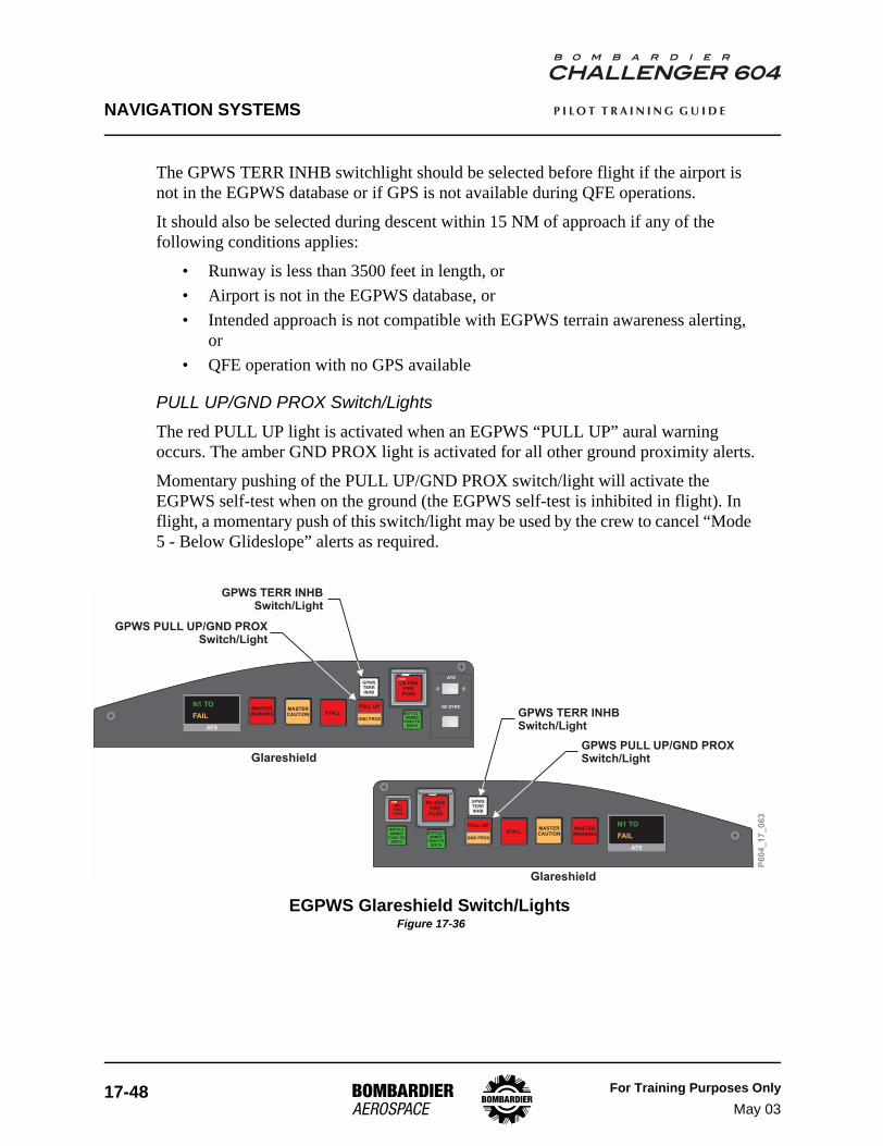
NAVIGATION SYSTEMS
17-48 For Training Purposes OnlyMay 03
P I L O T T R A I N I N G G U I D E
The GPWS TERR INHB switchlight should be selected before flight if the airport is not in the EGPWS database or if GPS is not available during QFE operations.
It should also be selected during descent within 15 NM of approach if any of the following conditions applies:
• Runway is less than 3500 feet in length, or• Airport is not in the EGPWS database, or• Intended approach is not compatible with EGPWS terrain awareness alerting,
or• QFE operation with no GPS available
PULL UP/GND PROX Switch/LightsThe red PULL UP light is activated when an EGPWS “PULL UP” aural warning occurs. The amber GND PROX light is activated for all other ground proximity alerts.
Momentary pushing of the PULL UP/GND PROX switch/light will activate the EGPWS self-test when on the ground (the EGPWS self-test is inhibited in flight). In flight, a momentary push of this switch/light may be used by the crew to cancel “Mode 5 - Below Glideslope” alerts as required.
EGPWS Glareshield Switch/Lights Figure 17-36
ATS
N1 TO
FAIL
APUFIREPUSH
RH ENGFIREPUSH
GPWSTERRINHB
MASTERWARNINGBOTTLE 2
ARMEDPUSH TO
DISCH
BOTTLEARMED
PUSH TODISCH
STALLMASTERCAUTION
PULL UP
GND PROX
LH ENGFIREPUSH
GPWSTERRINHB
MASTERWARNING BOTTLE 1
ARMEDPUSH TO
DISCH
STALLMASTERCAUTION
PULL UP
GND PROX
ATS
N2 SYNC
ATS
N1 TO
FAIL
P6
04
_1
7_
06
3Glareshield
Glareshield
GPWS TERR INHBSwitch/Light
GPWS PULL UP/GND PROXSwitch/Light
GPWS TERR INHBSwitch/Light
GPWS PULL UP/GND PROXSwitch/Light

NAVIGATION SYSTEMS
For Training Purposes OnlyMay 03
17-49
P I L O T T R A I N I N G G U I D E
Controls and Indicators
EGPWS Controls and Indicators Figure 17-37
LH ENGFIREPUSH
GPWSTERRINHB
MASTERWARNING BOTTLE 1
ARMEDPUSH TO
DISCH
STALLMASTERCAUTION
PULL UP
GND PROX
ATS
N2 SYNC
ATS
N1 TO
FAIL
P604_17_083
GLARESHIELD
GPWS TERR INHB Switch/Light (Alternate-action)Press
Illuminated white
- Inhibits Terrain Clearance Floor (TCF) and Terrain/ObstacleAwareness Alerting and Display (TAAD) Modes
- Indicates Terrain Inhibits is selected
PULL UP/GND PROX Switch/Light(Momentary-action)Press
PULL UP annunciator
GND PROX annunciator
-On the Ground - Initiates EGPWS self-testIn Flight - Cancels Mode 5 - Below Glideslope alerts
Flashes red - Indicates an EGPWS “PULL UP” alert isactive
Flashes amber - Indicates EGPWS caution alert isactive
GPWSFLAPOVRD
NORM
ADJACENT TO FLAP SECTION LEVERCENTE PEDESTALR
GPWS/FLAP Override(guarded toggle switch)GPWS/FLAP OVRD
NORM (guarded)
- Mutes flap auralwarning when entering the landingconfiguration with flaps at a position otherthan 45°
- Normal operation

NAVIGATION SYSTEMS
17-50 For Training Purposes OnlySept 04
P I L O T T R A I N I N G G U I D E
PFD Indications Figure 17-38
EGPWS Self-Test - Terrain Test Pattern Figure 17-39
P6
04
_1
7_
08
4
20
10
10
20
WINDSHEAR
Windshear MessageAmber
Red
- Flashes then comes on steady toindicate that the airplane is entering anincreasing performance windshearcondition
- Flashes then comes on steady toindicate that a severe decreasingperformance windshear condition has beenencountered
LX/TERRAIN TEST G+1 USTB T+10.7TAS 0 0
YUL
(8700)KDEN
(8215)0NM
2NM177NM
1NM0:010:31
0:00::::
CLIMB(8215)
ABOVEBELOW DME2
– – – –
USTB T-4.5UTC00:20 GS SAT-1C TAT-1C
VOR1 ADF2
5
10
328
(8700)
0:00/ 1NM618215A
(8215)KASE
/8700A
/8215A
P6
04
_1
7_
08
5
(8700)/8700A
(8215)KASE

NAVIGATION SYSTEMS
For Training Purposes OnlySept 04
17-51
P I L O T T R A I N I N G G U I D E
MFD Terrain Abnormal Annunciations Figure 17-40
EGPWS ABNORMAL ANNUNCIATION DESCRIPTION
TERRAIN FAILThe TAAD is inoperative due to an EGPWC internal fault or due to the failure of a required input.
TERRAIN NOT AVAIL
The TAAD and the TCF have been temporarily inhibited by the EGPWC because the estimated navigation accuracy from both the GPS and the FMS is insufficient.
TERRAIN CONTROL FAULTThe range of the terrain elevation data does not agree with the current MFD range.
EGPWS Abnormal Annunciation Table 17-8
LX/TERRAIN G+1 USTB T+10.7TAS 0 0
YUL
(8700)KDEN
(8215)0NM
2NM177NM
1NM0:010:31
0:00::::
CLIMB(8215)
ABOVEBELOW DME2
– – – –
USTB T-4.5UTC00:20 GS SAT-1C TAT-1C
VOR1 ADF2
5
10
328
(8700)
P6
04
_1
7_
08
6
0:00/ 1NM618215A
(8215)KASE
/8700A
/8215A
TERRAIN FAIL TERRAIN FAIL
(INTC)

NAVIGATION SYSTEMS
17-52 For Training Purposes OnlyMay 03
P I L O T T R A I N I N G G U I D E
EICAS MessagesThe following white EICAS status messages are provided to inform the crew when EGPWS functions are inoperative:
MESSAGE MEANING
GPWS FAIL The basic Ground Proximity Warning function (Mode 1 to 6) is inoperative.WINDSHEAR FAIL The windshear detection function is inoperative.
TERRAIN NOT AVAILThe terrain awareness alerting and display functions and the Terrain Clearance Floor function have been temporarily disabled by the EGPWS because the FMS navigation accuracy is insufficient.
TERRAIN FAIL The terrain awareness alerting and display functions and the Terrain Clearance Floor function are inoperative due to a fault condition.
EICAS Messages Table 17-9
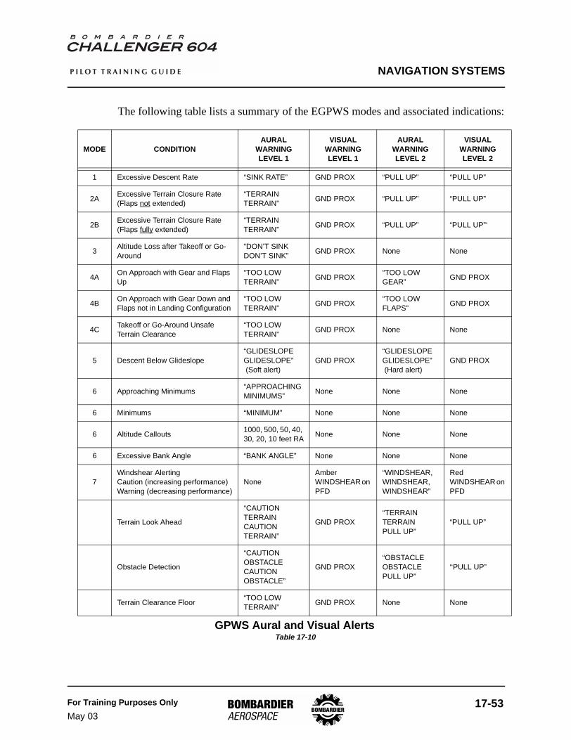
NAVIGATION SYSTEMS
For Training Purposes OnlyMay 03
17-53
P I L O T T R A I N I N G G U I D E
The following table lists a summary of the EGPWS modes and associated indications:
MODE CONDITIONAURAL
WARNING LEVEL 1
VISUAL WARNING LEVEL 1
AURAL WARNINGLEVEL 2
VISUAL WARNING LEVEL 2
1 Excessive Descent Rate “SINK RATE” GND PROX “PULL UP” “PULL UP”
2A Excessive Terrain Closure Rate(Flaps not extended)
“TERRAIN TERRAIN” GND PROX “PULL UP” “PULL UP”
2B Excessive Terrain Closure Rate(Flaps fully extended)
“TERRAIN TERRAIN” GND PROX “PULL UP” “PULL UP”‘
3 Altitude Loss after Takeoff or Go-Around
“DON’T SINK DON’T SINK” GND PROX None None
4A On Approach with Gear and Flaps Up
“TOO LOW TERRAIN” GND PROX “TOO LOW
GEAR” GND PROX
4B On Approach with Gear Down and Flaps not in Landing Configuration
“TOO LOW TERRAIN” GND PROX “TOO LOW
FLAPS” GND PROX
4C Takeoff or Go-Around Unsafe Terrain Clearance
“TOO LOW TERRAIN” GND PROX None None
5 Descent Below Glideslope“GLIDESLOPE GLIDESLOPE” (Soft alert)
GND PROX“GLIDESLOPE GLIDESLOPE” (Hard alert)
GND PROX
6 Approaching Minimums “APPROACHING MINIMUMS” None None None
6 Minimums “MINIMUM” None None None
6 Altitude Callouts 1000, 500, 50, 40, 30, 20, 10 feet RA None None None
6 Excessive Bank Angle “BANK ANGLE” None None None
7Windshear AlertingCaution (increasing performance)Warning (decreasing performance)
NoneAmber WINDSHEAR on PFD
“WINDSHEAR, WINDSHEAR, WINDSHEAR”
Red WINDSHEAR on PFD
Terrain Look Ahead
“CAUTION TERRAIN CAUTION TERRAIN”
GND PROX“TERRAIN TERRAIN PULL UP”
“PULL UP”
Obstacle Detection
“CAUTION OBSTACLE CAUTION OBSTACLE”
GND PROX“OBSTACLE OBSTACLE PULL UP”
‘‘PULL UP”
Terrain Clearance Floor “TOO LOW TERRAIN” GND PROX None None
GPWS Aural and Visual Alerts Table 17-10

17-54 For Training Purposes OnlyMay 03
NAVIGATION SYSTEMS P I L O T T R A I N I N G G U I D E
Page Intentionally Left Blank

NAVIGATION SYSTEMS
For Training Purposes OnlyMay 03
17-55
P I L O T T R A I N I N G G U I D E
VHF Navigation System
DescriptionThe VHF Navigation System is a dual-receiver system used for en route navigation and for precision approach and landing. Signals from VHF Omni Range (VOR), Instrument Landing System (ILS) stations and marker beacons are received and processed. Separate VOR and ILS modes of operation are provided.
The VHF Navigation System consists of two VHF Navigation Receivers and associated antennas.
Components and Operation
VHF Navigation Receiver
The VOR/LOC receiver operates in the frequency range of 108.0 MHz through 117.95 MHz. The frequencies are spaced 50 kHz apart, giving 200 channels. Forty channels are designated for Localizer and 150 channels are assigned to VOR. The frequency range of the Glideslope Receiver is 329.15 to 335.00 MHz. There are 40 channels with 150-kHz spacing. The Localizer and Glideslope channels are paired. The Marker Beacon operates on a fixed frequency of 75.0 MHz.
The VHF NAV 1 receiver is powered by the DC Essential Bus and VHF NAV 2 by DC Bus 2.
Nav Tuning
NAV tuning is normally performed from the top level page of the on-side RTU (see Figure 17-44). Tuning may also be accomplished by the cross-side RTU or by the FMS CDU.
When the NAV main display page is selected, the sensitivity of the marker beacon receiver can be controlled via the MKR SENS line select key.
Course Selection and Tracking
The desired VOR/LOC course may be displayed on the PFD horizontal situation indicator (HSI), by selecting VOR/LOC using the NAV SOURCE knob on the DCP, and then setting the desired course with the COURSE knob on the Flight Control Panel (FCP). Pushing the PUSH DIRECT inset button of the COURSE knob on the FCP sets the VOR course direct to the tuned VOR station.
The VOR/LOC course may also be displayed on the HSI and NAV SECTOR formats of the MFD.

NAVIGATION SYSTEMS
17-56 For Training Purposes OnlyMay 03
P I L O T T R A I N I N G G U I D E
Tracking of the VOR/LOC course is accomplished using the flight director and autopilot. For more information, see Chapter 4 Automatic Flight Control System.
Bearing Pointer Selection
The BRG pushbuttons on the DCPs allow selection of pilot’s side or copilot’s side VOR information in the form of bearing pointers. The single magenta bearing pointer displays the direct bearing to the NAV 1 VOR station. The cyan double bearing pointer displays the direct bearing to the NAV 2 VOR station.
Both pointers may be displayed simultaneously on either PFD’s HSI, and on the HSI, NAV SECTOR, and FMS MAP formats of the MFD.
Cross-Side Course Display
The PUSH X-SIDE inset button on the NAV SOURCE knob may be used to display cross-side course information on the HSI and NAV SECTOR MFD formats.
Controls and IndicatorsThe figures that follow outline the controls and indications relevant to VHF navigation. Refer to Chapter 6 Communications, and Chapter 11 Flight Instruments for additional information on the Radio Tuning Unit (RTU) and EFIS displays.
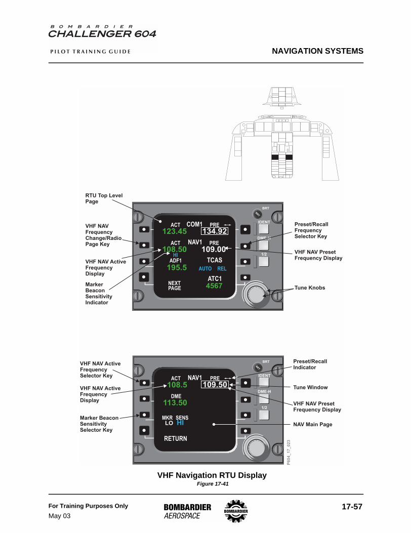
NAVIGATION SYSTEMS
For Training Purposes OnlyMay 03
17-57
P I L O T T R A I N I N G G U I D E
VHF Navigation RTU Display Figure 17-41
Preset/RecallIndicator
Tune Window
VHF NAV PresetFrequency Display
NAV Main Page
VHF NAV ActiveFrequencySelector Key
VHF NAV ActiveFrequencyDisplay
Marker BeaconSensitivitySelector Key
IDENT
DME-H
1/2
BRT
BRT
108.50ACT PRE
109.00NAV1
ACT PRE
123.45 134.92COM1
195.5ADF1 TCAS
AUTO
ATC1NEXTPAGE 4567
TONEREL
HI
IDENT
DME-H
1/2
BRT
BRT
ACT PRE
108.5 109.50NAV1
MKR
RETURN
TONE
SENS
DME
113.50
HILO
VHF NAVFrequencyChange/RadioPage Key
VHF NAV ActiveFrequencyDisplay
MarkerBeaconSensitivityIndicator
RTU Top LevelPage
Preset/RecallFrequencySelector Key
VHF NAV PresetFrequency Display
Tune KnobsP
60
4_
17
_0
23

NAVIGATION SYSTEMS
17-58 For Training Purposes OnlyMay 03
P I L O T T R A I N I N G G U I D E
Audio and Display Control Panel Figure 17-42
No. 1/2 Bearing PointerSource SwitchesPush to select No.1/2(single/dual bar) source:-OFF-VOR 1/2-ADF 1/2-FMS 1/2-(FMS 3)Source indicated onPFD/MFD.
NAVSOURCE
FORMAT RANGE
BRG TERR WX TFC
PUSH
X- S I D
E
1 - VHF - 2
1 - DME - 2
1 - NAV - 2 1 - MKR - 2
1 - ADF - 2
R/T
I/C
VOICE
BOTH
SPKR MASK
BOOM
EMER
NORM
PA
INT/SVCVHF 3 1 - HF - 2
Navigation Source KnobRotate to select navigationsource:-(FMS 3)-FMS 1-VOR 1 / LOC 1-OFF-VOR 2 / LOC 2-FMS 2-(FMS 3)
VOICE/BOTH SwitchVOICE
BOTH
– CW signals arefiltered out of VOR, ILSand ADF
– Stationidentification and voicesignals are audible
Navigation ReceiveSwitchesPress to monitorrespective navigationreceiver.Press again to deselect.Any number of audiosources can be monitoredat the same time.Rotate to adjust volume.
Marker Beacon ReceiveSwitches
3000 Hz1300 Hz
400 Hz
Press to monitor markerbeacon audio signals:
- inner marker- middle marker,
and- outer marker
Press again to deselect.Rotate to adjust volume.Marker-receive sensitivityand output volume are setby MKR sens mode, onNAV main page of RTU
AUDIO CONTROL PANEL
DISPLAY CONTROL PANEL
P6
04
_1
7_
02
4
Cross-side CourseSelection PushbuttonUsed only on MFD. In HSIand NAV sector formats,displays currently selectedcross-side course, alongwith course deviation andcourse labeling fromcross-side. Selection doesnot remove existing datafrom MFD. Push on/pushoff.
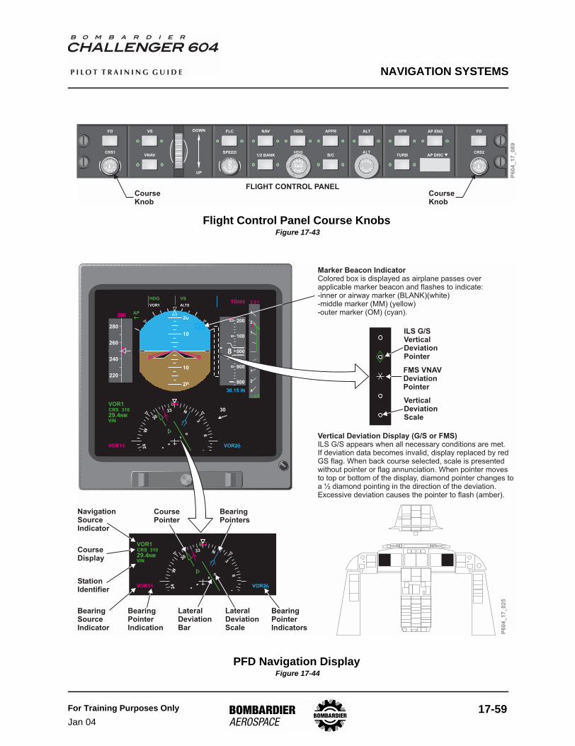
NAVIGATION SYSTEMS
For Training Purposes OnlyJan 04
17-59
P I L O T T R A I N I N G G U I D E
Flight Control Panel Course Knobs Figure 17-43
PFD Navigation Display Figure 17-44
FLC
SPEED
NAV HDG APPR
1/2 BANKHDG
B/C
ALT
ALTCRS1 CRS2
FD FDVS
VNAV
DOWN
UP
XFR
TURB AP DISC
AP ENG
P
USH
D
I R E C
T
IA
S/ M A
CH
PUSH
SY N C
PUSH
C
AN C E
L
P
USH
D
I R E C
T
FLIG T CONTROL PANELHCourseKnob
CourseKnob
P6
04
_1
7_
08
9
N33
30
W24
E6
3
VOR1
VOR1CRS
29.4NMVIN
310
VOR2
BRT
N33
30
W24
E6
3
20
10
10
20
260
220
240
280
000
900
800
100
200
19000
VOR1
30.15 IN
HDG DR VS
AP
1
2
4
1
2
4
1.9
250
8
M.452
VOR1CRS
29.4NMVIN
310
VOR13.0
30
VOR2
ALTS PATH GS10000
OM
BearingSourceIndicator
StationIdentifier
CourseDisplay
NavigationSourceIndicator
BearingPointerIndication
CoursePointer
BearingPointers
LateralDeviationScale
LateralDeviationBar
BearingPointerIndicators
ILS G/SVerticalDeviationPointer
VerticalDeviationScale
Vertical Deviation Display (G/S or FMS)ILS G/S appears when all necessary conditions are met.If deviation data becomes invalid, display replaced by redGS flag. When back course selected, scale is presentedwithout pointer or flag annunciation. When pointer movesto top or bottom of the display, diamond pointer changes toa ½ diamond pointing in the direction of the deviation.Excessive deviation causes the pointer to flash (amber).
Marker Beacon IndicatorColored box is displayed as airplane passes overapplicable marker beacon and flashes to indicate:-inner or airway marker (BLANK)(white)-middle marker (MM) (yellow)-outer marker (OM) (cyan).
FMS VNAVDeviationPointer
P6
04
_1
7_
02
5

NAVIGATION SYSTEMS
17-60 For Training Purposes OnlySept 04
P I L O T T R A I N I N G G U I D E
MFD Navigation Display Figure 17-45
BRT
VOR1 VOR2
WXUTC11 : 42
TTG : 0711
VOR1CID
CRS 350 FMS2 DTK 030
TAS GS SAT250 240 12C TAT–15CTGT
VIN30.0NM 104.7NMTTG : 2611
N33
30
W24
21
S 15
12
E6
3
340
MULTIFUNCTION DISPLAYPILOT'S AND COPILOT'S INSTRUMENT PANELS
MULTIFUNCTION DISPLAYPILOT'S AND COPILOT'S INSTRUMENT PANELS
No. 1 Bearing PointerPointer removed if bearing source failed.
No. 2 Bearing PointerPointer removed if bearing source failed.
VOR 1LOC 1FMS 1FMS 3
VOR 2LOC 2FMS 2FMS 3
VOR 1LOC 1FMS 1FMS 3
VOR 2LOC 2FMS 2FMS 3
MFD 1 MFD 2
VOR 1ADF 1FMS 1FMS 3
VOR 2ADF 2FMS 2FMS 3
VOR 1ADF 1FMS 1FMS 3
VOR 2ADF 2FMS 2FMS 3
MFD 1 MFD 2
To/From IndicatorIndicates direction to or from a tuned VOR or selectedwaypoint. Color matches navigation source.
Course PointerIndicates the active NAV course. The value isnumerically repeated in the course display.
Course Display
COURSE/DESIRED TRACK POINTER
BEARING POINTER
Lateral Deviation ScaleIndicates relative deviation.
Lateral Deviation BarIndicates airplane deviation from VOR or localizerbeam.
P6
04
_1
7_
02
6
Bearing Source IndicatorIndicates navigation source selected to obtainbearings.
BRT
VOR1 VOR2
LX/WX+TRB+GCSUTC11 : 42
TTG : 0711
VOR1CID
CRS 350 FMS2 DTK 030
TAS GS SAT250 240 15C TAT–15CTGT
VIN30.0NM 104.0NMTTG : 2611
50
100
340
G+3 USTB T+10.7
ALO
CID
DBQ

NAVIGATION SYSTEMS
For Training Purposes OnlySept 04
17-61
P I L O T T R A I N I N G G U I D E
PFD - VHF NAV - Failure Displays Figure 17-46
NavigationSource Flag
BRT
VOR1
N33
30
W24
E6
3
FDATT
GS
RA
TRUDCP2
LOC1FMS1
VOR2
ALTVS
IAS
DTK
29.4NMVIN
MSG1MSG2
072
DisplayControl PanelSource Flag
GlidescopeVerticalDeviationFlag
HeadingFlag
ExcessiveLateralDeviation/LocalizerComparatorIndicator
Will be absent if system isnot functioning
P6
04
_1
7_
02
7

NAVIGATION SYSTEMS
17-62 For Training Purposes OnlyMay 03
P I L O T T R A I N I N G G U I D E
Distance Measuring Equipment (DME) System
DescriptionThere are two Distance Measuring Equipment (DME) receivers installed on the Challenger 604, DME 1 and DME 2. The DME systems measure the slant distance between the aircraft and a ground station to a maximum range of 300 nautical miles. Distance information is supplied to the FMSs, the PFDs and the MFDs.
Components and Operation
DME Transceivers
The DME transceivers compute distance for display on PFDs and MFDs and also provide position updating data to the FMSs.
The transceivers transmit, receive and process RF signals to produce slant range to a ground station. The DME frequency range consists of 252 channels in the frequency band of 962 to 1213 MHz, designated as X and Y channels 1 to 126.
DME 1 is powered by DC Bus 1, and DME 2 is powered by DC Bus 2.
Tuning
Each DME is a three-channel transceiver. Channel one is manually tuned by the on-side RTU, the cross-side RTU or by the FMS. Channels two and three are automatically tuned by the FMS and are used for multisensor navigation.
DME Hold
Pushing the DME-H key (on the right side of each RTU) holds the last DME frequency. This permits changing to, and working with, another VOR/LOC station while still receiving DME distance information from the last DME station.
DME Aural Identification
The DME three-letter Morse code identifier is supplied to the audio integrating system. Audio outputs are monitored using the DME 1 and DME 2 switches on the audio control panels. When listening to other NAV idents simultaneously, the DME is recognizable by its higher pitch.

NAVIGATION SYSTEMS
For Training Purposes OnlyMay 03
17-63
P I L O T T R A I N I N G G U I D E
DME Status Page Selection
The DME status page can be selected by pushing the MFD MENU switch on the FMS Control Display Unit, followed by pressing the VOR STATUS line select key. For each DME channel, the following data is displayed:
• received DME ident• received DME frequency• received DME slant range
The identifier shown adjacent to the DME label corresponds to the ident received from the DME sensor. The display of an identifier adjacent to the VOR label is determined by the FMS. If a DME is in Hold mode, its frequency is followed with an amber “H”.

NAVIGATION SYSTEMS
17-64 For Training Purposes OnlyMay 03
P I L O T T R A I N I N G G U I D E
MFD - VOR / DME Status Page Figure 17-47
DIR LEGSDEPARR
FPLN IDX TUNE
MFDDATA
MFDMENU
MFDADV
PERF PREV NEXT
A
G1 2 3
M
S
Y
B C
SP
D
DEL
E F
H
N
T
Z
I
O
U
J
P
V
K
Q
W
/
L
R
X
CLR
4
7
.
5
8
O
6
9
+/-
BRT
SOURCEVOR 1
DME 1 - 1
DME 1 - 2
DME 1 - 3
VOR 2
DME 2 - 1
DME 2 - 2
DME 2 - 3
IDIOW
IOW
-------
DSM
CID
CID
ALO
LNR
FREQ116.2
116.2
111.6
114.1
117.6
117.6H
112.2
112.8
BRG/DIST337.4
14.1 NM
----.-- NM
77.9 NM
191.0°
21.5
63.3
126.4
VOR/DME STATUS
P6
04
_1
7_
03
5
MSG EXEC
POS BRT
VOR STATUS
LRN STATUS
INSTERS
ARFTS
TERM WPTS
L/ >R
TO+APPR REF
FPLN PROG
NAV STATUS
POS SUMMARY
POS REPORT
SEC FPLN
R MAP
R
E
DATE
R
SIDE
L TEXT PG
ACTIVE DATA BASE
SEC DATA BASE
UTC
PROGRAM
L
LEFT DISPLAY MENU 1/2
[ ]
MSG
TEXT DISPLAY
NAVIGATION SYSTEMS
For Training Purposes OnlyMay 03
17-65
P I L O T T R A I N I N G G U I D E
Controls and IndicatorsThe DME distance and station identifier are displayed in the lower left corner of the PFD. When DME system information is not valid or unavailable, the DME distance display is removed.
On the PFD, the H annunciator next to the frequency readout indicates that the HOLD mode has been selected.
On the MFD, DME information is displayed on the upper left corner of the HSI and NAV SECTOR format when VOR/LOC is selected as the NAV SOURCE.
On aircraft equipped with “Precision Plus”, DME 1 and DME 2 are continuously displayed on the left and right sides of the MFDs.
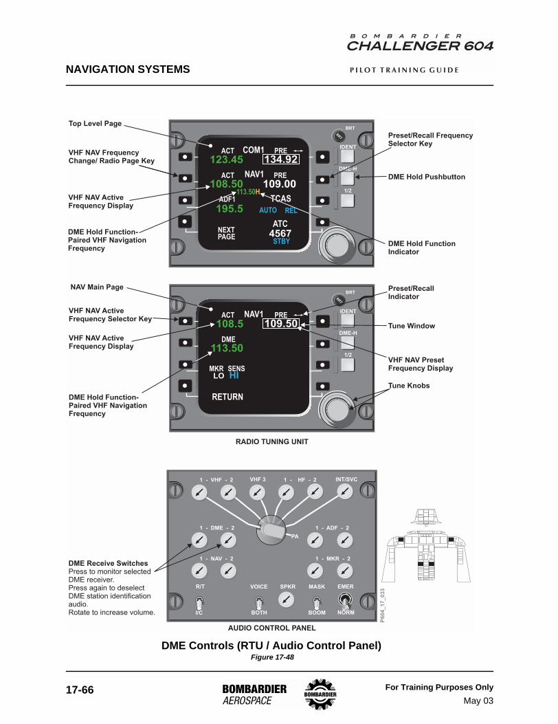
NAVIGATION SYSTEMS
17-66 For Training Purposes OnlyMay 03
P I L O T T R A I N I N G G U I D E
DME Controls (RTU / Audio Control Panel) Figure 17-48
IDENT
DME-H
1/2
BRT
BRT
108.50ACT PRE
109.00NAV1
ACT PRE
123.45 134.92COM1
195.5ADF1 TCAS
AUTO REL
ATCNEXTPAGE 4567
STBY
TONE
1 - VHF - 2
1 - DME - 2
1 - NAV - 2 1 - MKR - 2
1 - ADF - 2
R/T
I/C
VOICE
BOTH
SPKR MASK
BOOM
EMER
NORM
PA
INT/SVCVHF 3 1 - HF - 2
IDENT
DME-H
1/2
BRT
BRT
ACT PRE
108.5 109.50NAV1
MKR
RETURN
TONE
SENS
DME
113.50
HILO
Top Level Page
VHF NAV FrequencyChange/ Radio Page Key
VHF NAV ActiveFrequency Display
DME Hold Function-Paired VHF NavigationFrequency
DME Hold Function-Paired VHF NavigationFrequency
Preset/Recall FrequencySelector Key
VHF NAV PresetFrequency Display
DME Hold FunctionIndicator
Preset/RecallIndicator
Tune Window
Tune Knobs
DME Hold Pushbutton
NAV Main Page
VHF NAV ActiveFrequency Selector Key
VHF NAV ActiveFrequency Display
DME Receive SwitchesPress to monitor selectedDME receiver.Press again to deselect
station identificationaudio.Rotate to increase volume.
DME
RADIO TUNING UNIT
AUDIO CONTROL PANEL
P6
04
_1
7_
03
3
113.50H

NAVIGATION SYSTEMS
For Training Purposes OnlyJan 04
17-67
P I L O T T R A I N I N G G U I D E
.
DME Displays (PFD / MFD) Figure 17-49
ADF1 ADF2
LX/WX+TRB+GCSUTC11 : 42
TTG : 07
VOR1CID
CRS 350 FMS2 DTK 030
TAS GS SAT250 250 15C TAT–15CTGT
VIN30.0NM 104.0NMTTG : 2611
50
100
340
G+3 USTB T+10.7
ALO
CID
DBQ
N33
30
W24
E6
3
20
10
10
20T
220
200
180
160
000
900
800
100
200
ADF1
30.15 IN
HDG DR ALTS
AP
1
2
4
1
2
4
190
3
M.452
LOC1CRS
15.4NMVIN
310
LOC1
15
VOR2
ALTS GS1500
H
2400FT
MULTIFUNCTION DISPLAY(NAV SECTOR PAGE)
PRIMARY FLIGHT DISPLAYPILOT'S AND COPILOT'S INSTRUMENT PANELS
Distance ReadoutIndicates DME distance (slantrange maximum 300 NM) totuned navigation aid.
DME HOLD (H) SymbolWhen DME-H is selected, Hreplaces NM legend on distancereadout.
(yellow)
Distance Display
NavigationSource Indicator
Station Identifier
Time-To-Go Display
Nautical Miles (NM)DME Hold (H) Symbol
Ground Speed Readout (white)
When VOR is navigation source, readout indicates
DME ground speed.
When DME failed, readout and label blanked.
Cross-SideCourseDisplays
VOR 1LOC 1FMS 1FMS 3
VOR 2LOC 2FMS 2FMS 3
VOR 1LOC 1FMS 1FMS 3
VOR 2LOC 2FMS 2FMS 3
PFD 1 PFD 2
P6
04
_1
7_
03
4
YUL
LX/RADAR OFF G+3 USTB T+10.7TAS 345 345
YUL
THUROCYOW
HOKKE15NM
26NM66NM
9NM0:050:15
0:02::::
DIRECTTEXEN
3.3°2600A0:11/
2000
56NM
DME1
YUL
615.
G+3 USTB T+5.0UTC01: 06 GS SAT-29C TAT-13C
VOR1 ADF2
HOKKE
THURO
25
50
280
26000A
DME2
YUL
615.
ABOVEBELOW
MULTIFUNCTION DISPLAY(FMS MAP PAGE)

NAVIGATION SYSTEMS
17-68 For Training Purposes OnlyMay 03
P I L O T T R A I N I N G G U I D E
Automatic Direction Finder (ADF) System
DescriptionThe Automatic Direction Finder (ADF) system is a dual low-frequency radio navigation system (ADF 1 and ADF 2). The receivers are independently tunable in 0.5-kHz increments, in the frequency ranges of 190.0 to 1799.5 kHz and 2179 to 2185 kHz. The transmitting stations can be non-directional beacons (NDBs) or standard AM broadcasting stations.
Components and Operation
ADF Receivers
The ADF receivers supply bearing-to-station and audio outputs to the navigation and audio systems, and digital bus outputs to the Integrated Avionics Processor System (IAPS) and Electronic Flight Instrument System (EFIS).
ADF 1 is powered by the DC essential bus, and ADF 2 is powered by the DC bus 2.
ADF Antenna
The ADF Antenna contains one sense antenna and two loop antennas mounted 90° relative to each other.
ADF Tuning
The ADF receiver is normally tuned by the on-side RTU, but may also be tuned by the cross-side RTU or by the FMS. The audio is controlled by ADF 1 and ADF 2 switches on the audio control panel. A VOICE/BOTH switch filters out the station identification or selects both identification and voice.
When the 1/2 switch on the RTU is pushed, each RTU can control the on-side and cross-side ADF receivers.
ADF Bearing Pointer Selection and Navigation
The BRG pushbuttons on the DCPs allow selection of pilot's side or copilot's side ADF information in the form of bearing pointers. The magenta single bearing pointer displays the direct bearing to the ADF 1 station. The cyan double bearing pointer displays the direct bearing to the ADF 2 station.
Both pointers may be displayed simultaneously on either PFD’s HSI, and on the HSI, NAV SECTOR, and FMS MAP formats of the MFD.

NAVIGATION SYSTEMS
For Training Purposes OnlyMay 03
17-69
P I L O T T R A I N I N G G U I D E
ADF bearings cannot be coupled to course tracking or flight guidance systems. If navigation is being conducted using ADF information, the pilot is responsible to assign heading or course commands using the airplane’s other navigational systems.
ADF Operation Modes
The ADF system has two selectable modes of operation: ANT and ADF.
• when ANT is selected on the ADF page of the RTU, the NDB station signal may be received at long range, but no bearing information is available
• when ADF is selected, the reception range for the NDB signal is reduced, but bearing to the station is available
ADF Failure Indication
An ADF system failure is displayed as follows:
• the ADF frequency display on the RTU top level page is replaced with dashes• on the pilot’s and copilot’s PFDs and MFDs, the applicable bearing pointer is
removed• the applicable magenta or cyan bearing source indicator is replaced with a red
boxed bearing source indicator
ADF Self-test
To conduct the self-test, the ADF receiver must be in the ADF mode with a valid NDB frequency tuned in. The self-test is started by pushing the ADF TEST key on the RTU ADF main page. During the test, the bearing pointer rotates 90 degrees counterclockwise and the tone generator activates. The self-test is completed when the bearing pointer returns to its original bearing.
Controls and IndicatorsThe figures that follow outline the controls and indications relevant to ADF navigation. Refer to Chapter 6 Communications and Chapter 11 Flight Instruments for additional information on the Radio Tuning Unit (RTU) and EFIS displays.

NAVIGATION SYSTEMS
17-70 For Training Purposes OnlyJan 04
P I L O T T R A I N I N G G U I D E
ADF Bearing Display (PFD) Figure 17-50
No. 1 Bearing PointerSource SwitchesPush to select No.1 source:-OFF-VOR 1-ADF 1-FMS 1-(FMS 3)Source indicated onPFD/MFD.
BRT
N33
30
W24
E6
3
20
10
10
20
260
220
240
280
000
900
800
100
200
19000
ADF1
30.15 IN
HDG DR VS
AP
1
2
4
1
2
4
1.9
250
8
M.452
VOR1CRS
29.4NMVIN
310
VOR13.0
30
ADF2
ALTS PATH GS10000
NAVSOURCE
FORMAT RANGE
BRG TERR WX TFC
PUSH
X- S I D
E
PRIMARY FLIGHT DISPLAY
DISPLAY CONTROL PANELS
No. 1 Bearing SourceIndicatorIndicates navigation sourceselected to obtain No. 1bearing
No. 2 Bearing SourceIndicatorIndicates navigation sourceselected to obtain No. 2bearing
No. 1 Bearing PointerIndicates bearing to VOR,ADF or FMS navigationsource selected on displaycontrol panel. Pointerremoved if navigation sourcefailed
No. 2 Bearing PointerIndicates bearing to VOR,ADF navigationsource selected on displaycontrol panel. Pointerremoved if navigation sourcefailed
or FMS
VOR 1ADF 1FMS 1FMS 3
VOR 2ADF 2FMS 2FMS 3
VOR 1ADF 1FMS 1FMS 3
VOR 2ADF 2FMS 2FMS 3
PFD 1 PFD 2
BEARING POINTERP
60
4_
17
_0
29
No. 2 Bearing PointerSource SwitchesPush to select No.2(single/dual bar) source:-OFF-VOR 2-ADF 2-FMS 2-(FMS 3)Source indicated onPFD/MFD.
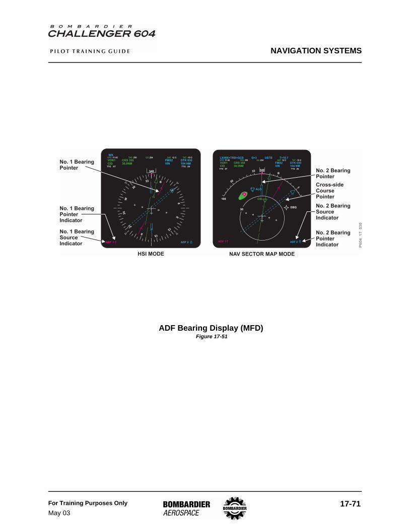
NAVIGATION SYSTEMS
For Training Purposes OnlyMay 03
17-71
P I L O T T R A I N I N G G U I D E
ADF Bearing Display (MFD) Figure 17-51
DBQ
ALO
CID
30
33 340N
3
50
ADF 1 ADF 2
100
LX/WX+TRB+GCS G+3 USTB T+10.7UTC TAS GS TAT11:42 250 254 SAT 12 C -15 C
VOR1CID
CRS 35030.0NM
FMS2VIN
DTK 030104 NMTTG :26TTG :07
No. 2 BearingPointer
No. 2 BearingSourceIndicator
No. 2 BearingPointerIndicator
NAV SECTOR MAP MODEHSI MODE
No. 1 BearingPointer
No. 1 BearingSourceIndicator
No. 1 BearingPointerIndicator
340
ADF 1 ADF 2
WXUTC TAS GS TAT11:42 250 254 SAT 12 C -15 C
VOR1CID
CRS 35030.0NM
FMS2VIN
DTK 030104 NMTTG :26TTG :07
33
30
21
S 15
12
6
3
N
E
W24
Cross-sideCoursePointer
P6
04
17
03
0

NAVIGATION SYSTEMS
17-72 For Training Purposes OnlyMay 03
P I L O T T R A I N I N G G U I D E
ADF Controls (RTU / Audio Control Panel) Figure 17-52
Tone Key
ON
Selects tone circuit either on oroff.
– Superimposes an auralsignal on unmodulated carrierwaves to aid in precisefrequency selection.
1 - DME - 2
1 - NAV - 2 1 - MKR - 2
1 - ADF - 2
R/T
I/C
VOICE
BOTH
SPKR MASK
BOOM
EMER
NORM
PA
IDENT
DME-H
1/2
BRT
BRT
108.50ACT PRE
109.00NAV1
ACT PRE
123.45 134.92COM1
195.5ADF1 TCAS
AUTO REL
ATCNEXTPAGE 4567
STBY
TONE
IDENT
DME-H
1/2
BRT
BRT
MODE
238.0ADF1
RETURN
TONE
TONE
TEST
ADF ANT
OFF ON
Top Level Page
ADF FREQ ReadoutIndicates active ADF frequency
FREQ Change / Radio PageKeyTune
Radio Page
– Push key once todirectly tune active frequencywith tuning knobs
– Push key twice toselect ADF main page
ADF Mode Key
ANT
ADF
Selects either ADF or antennafunctions:
– Used for rangenavigation, optimum stationtuning, or monitoring.
– Used to select directionalantenna which seeks signalsource. Bearing to selectedstation is displayed on the HSIportion of the primary flightdisplay or the multifunctiondisplay.
VOICE / BOTH SwitchVOICE
BOTH
– Station identificationCW signals are filtered out ofVOR, ILS and ADF audio
– Station identificationand voice signals are audible
AUDIO CONTROL PANELS
ADF Main Level PageUsed to select ADF modes andfrequencies
FREQ ReadoutIndicates active ADF frequency
ADF Receive SwitchesPress to monitor selected ADFreceiver.Press again to deselect ADFreceiver audio.Rotate to increase volume
TESTInitiates self-test. Pointer rotates90° CCW, tone activates
P6
04
_1
7_
03
1
RTU(Pilot Shown)
RTU(Pilot Shown)

NAVIGATION SYSTEMS
For Training Purposes OnlyMay 03
17-73
P I L O T T R A I N I N G G U I D E
Air Traffic Control (ATC) Transponder System
DescriptionThe ATC Transponder system is an automatic altitude and identification reporting unit which responds to ground ATC interrogators and airborne traffic alert and collision avoidance system (TCAS) interrogators.
There two Air Traffic Control transponders, ATC 1 and ATC 2. The transponders have three modes of operation:
• Mode A - aircraft identity reporting• Mode C - altitude reporting• Mode S - data links with other mode C and S transponders for the traffic collision
avoidance system (TCAS)
Components and Operation
Transponder
The solid-state transponders receive and decode air traffic control interrogations and reply automatically. The system can receive but cannot reply to interrogations when on the ground.
The ATC 1 system is powered by the DC Essential Bus, and the ATC 2 system is powered by DC Bus 2.
Antennas
Each transponder system has two paired antennas. Each system has an upper and lower antenna located on the forward fuselage.

NAVIGATION SYSTEMS
17-74 For Training Purposes OnlyMay 03
P I L O T T R A I N I N G G U I D E
Controls and Indicators
ATC Selector Knob
The ATC selector knob is located on the REVERSIONARY / INHIBIT panel of the center pedestal. The selector has three positions: 1, STBY and 2. When ATC 1 transponder is selected, it uses altitude information from ADC 1 to respond to mode C and mode S interrogations. ATC 2 receives altitude information from ADC 2. When either transponder is selected, the RTU four-digit identification code turns green. When in STBY, the RTU code is white.
In RVSM airspace, the pressure altitude source for the transponder must be the same as the pressure source used by the automatic altitude control system (i.e., the flight director and autopilot). If flight director 1 is in use, select ATC 1 as the transponder. If flight director 2 is in use, select ATC 2 as the transponder.
Code Selection
Selection of ATC identification code and altitude reporting are performed via the ATC Main Page on the RTUs. The TUNE page on the FMS permits manual selection of the ATC code.
NOTE

NAVIGATION SYSTEMS
For Training Purposes OnlyMay 03
17-75
P I L O T T R A I N I N G G U I D E
Transponder Controls (RTU) Figure 17-53
IDENT
DME-H
1/2
BRT
BRT
ALT
4567ATC
RETURN
TONE
ON OFF
41000
STBY R
IDENT
DME-H
1/2
BRT
BRT
108.50ACT PRE
109.00NAV1
ACT PRE
123.45 134.92COM1
195.5ADF1 TCAS
AUTO
ATC1NEXTPAGE 4567
TONEREL
ALT OFF ID
IDENT Pushbutton
ATC Identification CodeSelector Key
ATC Identification CodeDisplay
Altitude Mode Off IndicatorSTBY Mode
Top Level Page
Tune Indicator
Tune Window
Altitude Mode Selector Key
ATC Main Page
Reply Indicator
Reported Altitude DisplayStandby Mode Indicator
P604_17_037
IDENT Indicator or R ForReply

17-76 For Training Purposes OnlyMay 03
NAVIGATION SYSTEMS P I L O T T R A I N I N G G U I D E
Page Intentionally Left Blank

NAVIGATION SYSTEMS
For Training Purposes OnlyMay 03
17-77
P I L O T T R A I N I N G G U I D E
Transponder Controls (Reversionary / Inhibit Panel) Figure 17-54
ATC SELSelects No. 1 or No. 2ATC Transponder
P6
04
_1
7_
03
8
INHIBIT PUSH
1-RTU-2 FMS TUNE
1 2
AFCSSEL
STBY
1 2
ATCSEL
FMSTUNEINHIB
RTU 1INHIB
RTU 2INHIB
1 21 2

NAVIGATION SYSTEMS
17-78 For Training Purposes OnlyMay 03
P I L O T T R A I N I N G G U I D E
Traffic Alert and Collision Avoidance System (TCAS)
DescriptionThe TCAS is an airborne traffic surveillance system that provides collision avoidance alerts and conflict resolution cues to pilots. Operating with the Mode-S transponder, interrogations are transmitted, responses from other similarly equipped aircraft are received and analyzed, potential traffic threats are identified and displayed, and conflict resolutions are presented visually and aurally.
TCAS monitors a radius of approximately 5 to 40 NM around the aircraft. The TCAS transceiver transmits mode-C and mode-S transponder interrogation signals and monitors all replies. Internal processing determines the range, bearing, and altitude of each transponder-equipped aircraft within range. When a conflict exists, the TCAS generates traffic advisory (intruder alert), resolution advisory (recommended vertical escape maneuver), and/or synthesized-voice audio outputs. When an intruder aircraft is also equipped with a functioning mode-S transponder, the TCAS uses the transponder to transmit collision avoidance data to that aircraft. This mode-S link allows the two TCAS systems to coordinate conflict resolution between aircraft.
Components and Operation
TCAS Transmitter / Receiver
The TCAS transmitter / receiver contains the TCAS computer, and is installed in the underfloor avionics compartment. It selectively transmits interrogation signals, receives and analyzes the responses, determines if potential conflicts exist, generates collision avoidance solutions, and formats the data to visually and/or aurally present that information to the pilots.
The TCAS transmitter / receiver receives bearing information from the TCAS directional antenna on the top of the fuselage, and receives altitude information from the TCAS omnidirectional antenna located on the underside of the fuselage.
Power for the TCAS transmitter / receiver is supplied by the AC Essential Bus.
TCAS Traffic SymbologyThe TCAS computer classifies nearby aircraft into one of four types:
• Other traffic (OT)• Proximate traffic (PT)• Traffic alert (TA)• Resolution advisory (RA)

NAVIGATION SYSTEMS
For Training Purposes OnlyMay 03
17-79
P I L O T T R A I N I N G G U I D E
TCAS MFD Traffic Symbology Display Figure 17-55
BRT
T+10.7250 SAT 12C
10
LX/WX+TRBTAS 254
USTBUTC11:42 GS TAT-15C
FMS2YUL
G+3
+10
+01
RA 2. / 00TA 4. / -03
0NM
0NM
ABOVEBELOW
ALT180
-OFF
-02
+07
- 45
RA Traffic
TA Traffic
Proximate Traffic
Other Traffic
IntruderSymbol
ALT Data(REL/ABS Altitudex 100 feet)
VS Arrow(if VS > 500 fpm)
Traffic Detail: The following TCAS messages may display on theMFD screens:
The following TCAS messages may display on the PFDscreens:
Message
Message
Meaning
Meaning
TCAS FAILTCAS TESTTD FAIL
TRAFFICRA FAILTCAS FAILTCAS OFFTCAS TEST
TCAS system failure (amber)TCAS computer is in test mode (white)TCAS data not received (amber)
RA (red) or TA (amber) intruder detectedTCAS data not received (amber)TCAS system failure (amber)TCAS system is off (white)TCAS computer is in test mode (white)
TCAS TRAFFIC MAP FORMAT
TCASModeDisplay
TCASAltitudeDisplay
Traffic Symbol
RangeDistance
RangeRings
AircraftSymbol
No BearingAdvisoryWindow
Example:
RA traffic alert –intruder at 10:30; 4miles away, 700 feetabove, descendinggreater than 500 fpm
Azimuth TickMarks
P6
04
_1
7_
04
3
Intruder Symbology:
NAVIGATION SYSTEMS
17-80 For Training Purposes OnlyMay 03
P I L O T T R A I N I N G G U I D E
Other Traffic (OT)
Other Traffic (OT) is non-threat traffic within the TCAS surveillance area. The display of OT symbols on the MFD may be set to on or off. The control for this function is located on the RTU TCAS main display page.
Other Traffic is available for display in variable altitude volumes. The controls for this feature are also located on the RTU TCAS main display page. “NORMAL” mode is the default mode. “NORMAL” mode sets the OT window from between 2700 feet above to 2700 feet below own airplane altitude. Selecting “BELOW” extends the lower portion of the OT window to 9900 feet below own airplane altitude. Selecting “ABOVE” extends the upper portion of the OT window to 9900 feet above own airplane altitude.
Proximate Traffic (PT)
Proximate traffic are non-threat aircraft within ± 1200 feet relative altitude and six NM of own aircraft. Proximate traffic cannot be deselected, and is always shown on the traffic display as an aid to the pilots when visually acquiring TAs and RAs.
Traffic Alert (TA)
The TCAS computer issues Traffic Alerts as appropriate when TA/RA mode is active. TA/RA mode is selected on the TCAS RTU main menu page. Traffic alerts are issued for non-threat intruder aircraft that should be monitored because, depending upon their continued flight path, they may become RA traffic. Traffic alerts are issued aurally and visually on the MFD, starting 20 to 48 seconds before the calculated closest point of approach. The audio message “TRAFFIC, TRAFFIC” is annunciated over the aircraft audio system, and the message “TRAFFIC” shows in yellow below the VSI on the PFD when the system detects TA traffic.
When the TCAS computer is operating in TA ONLY mode, RA traffic shows as TA traffic, and no commanded vertical speeds show on the PFD. TA ONLY mode is selected via the RTU TCAS main display page. “TA ONLY” shows in white on the PFD when the system is operating in TA ONLY mode. “TA ONLY” shows in yellow when the system is operating in the TA ONLY mode and TA traffic is detected.
TA ONLY mode is automatically selected when below 1100 feet AGL on takeoff and 900 feet AGL on landing.
NOTE

NAVIGATION SYSTEMS
For Training Purposes OnlyMay 03
17-81
P I L O T T R A I N I N G G U I D E
Resolution Advisory (RA)
The TCAS computer issues Resolution Advisories as appropriate when TA/RA mode is active. TA/RA mode is selected on the TCAS RTU main menu page. When the system determines a potential threat requires immediate pilot action, a resolution advisory shows on the MFD. The TCAS system gives an RA on the PFD in the form of a vertical speed command designed to increase the separation between the intruding threat aircraft and own aircraft.
Resolution advisories show as red-only, or red-and-green bands. To comply with a resolution advisory, avoid flying vertical speeds within the red banded areas, and fly the vertical speeds within the green banded areas (if presented). “TRAFFIC” shows in red below the vertical speed scale on the PFD when the system detects RA traffic. There are two types of RA: corrective and preventive.
Corrective RA:A corrective RA is issued if the TCAS computer has determined that corrective action needs to be taken to avoid the threat traffic. The computer displays the vertical speed range to seek and/or avoid on the PFD vertical speed display. Corrective RA audio annunciations are issued by the TCAS computer over the cockpit audio system. (See Table 17-12).
Preventive RA:A preventive RA is issued if the TCAS computer has determined that the current vertical speed will resolve the threat situation. The computer displays the vertical speed range to maintain, and the vertical speed range to avoid, on the PFD vertical speed display. The command “Monitor Vertical Speed” is issued by the TCAS computer over the cockpit audio system.
RA Communication and Coordination
In a case where both aircraft are TCAS equipped, the TCAS communicates with the other aircraft to coordinate evasive strategies. This coordination may occur before an advisory is issued and is calculated for optimum safe separation using the least disruptive maneuver possible. For example, if one aircraft is in a particular vertical speed (VS) profile, it may be advantageous for that aircraft to increase or decrease its VS as opposed to the other assuming an evasive VS. Whatever maneuver is selected, this information is communicated to other aircraft and ground facilities.
If the other aircraft is not TCAS equipped, the corrective or preventive maneuver responsibility is assumed by the TCAS-equipped aircraft, and only the ground facility communication is possible.

NAVIGATION SYSTEMS
17-82 For Training Purposes OnlyMay 03
P I L O T T R A I N I N G G U I D E
TCAS Vertical Speed Advisories Figure 17-56
TCAS ADVISORY RANGE THRESHOLD (SECONDS)
ALTITUDE THRESHOLD (FEET)
FIXED RANGE THRESHOLD, USED
WITH SLOW CLOSURE RATES (NMI)
V6.04a V7 V6.04a V7 V6.04a V7
Traffic advisory
FL200 - FL300 48 48 850 850 1.3 1.3
FL300 - FL420 48 48 1200 850 1.3 1.3
Corrective RA
FL200 - FL300 35 35 600 600 1.1 1.1
FL300 - FL420 35 35 700 600 1.1 1.1
Preventive RA
FL200 - FL300 35 35 700 700 1.1 1.1
FL300 - FL420 35 35 800 700 1.1 1.1
TCAS Threat Resolution Parameters Table 17-11
P6
04
_1
7_
09
8
1
2
4
1
2
4
1
2
4
1
2
4
1
2
4
1
2
4
1
2
4
1
2
4
1
2
4
1
2
4
1
2
4
1
2
4
CLIMBPREVENTIVE
DESCENTPREVENTIVE
CLIMBCORRECTIVE
DESCENTCORRECTIVE
CLIMB PREVENTIVE/CLIMB CORRECTIVE
DESCEND PREVENTIVE/CORRECTIVEDESCEND

NAVIGATION SYSTEMS
For Training Purposes OnlyMay 03
17-83
P I L O T T R A I N I N G G U I D E
TCAS ADVISORY VERSION 7 AURAL ANNUNCIATION VERSION 6.04 AURAL ANNUNCIATION
Traffic Advisory Traffic, Traffic Traffic, Traffic
Climb RA Climb, Climb Climb, Climb, Climb
Descend RA Descend, Descend Descend, Descend, Descend
Altitude Crossing Climb RA Climb, Crossing Climb; Climb, Crossing Climb
Climb, Crossing Climb; Climb, Crossing Climb
Altitude Crossing Descend RA Descend, Crossing Descend;Descend, Crossing Descend
Descend, Crossing Descend;Descend, Crossing Descend
Reduce Climb RA Adjust Vertical Speed, Adjust Reduce Climb,Reduce Climb
Reduce Descent RA Adjust Vertical Speed, Adjust Reduce Descent,Reduce Descent
RA Reversal to a Climb RA Climb, Climb NOW;Climb, Climb NOW
Climb, Climb NOW;Climb, Climb NOW
RA Reversal to a Descend RA Descend, Descend NOW; Descend, Descend NOW
Descend, Descend NOW;Descend, Descend NOW
Increase Climb RA Increase Climb, Increase Climb Increase Climb, Increase Climb
Increase Descent RA Increase Descent, Increase Descent
Increase Descent,Increase Descent
Maintain Rate RA Maintain Vertical Speed, Maintain Monitor Vertical Speed
Altitude Crossing, MaintainRate RA (Climb and Descend)
Maintain Vertical Speed, Crossing Maintain Monitor Vertical Speed
Weakening of Initial RA Adjust Vertical Speed,Adjust Monitor Vertical Speed
Preventive RA (No change invertical speed required) Monitor Vertical Speed Monitor Vertical Speed,
Monitor Vertical Speed
RA Removed Clear of Conflict Clear of Conflict
TCAS Aural Annunciation Table Table 17-12

NAVIGATION SYSTEMS
17-84 For Training Purposes OnlyMay 03
P I L O T T R A I N I N G G U I D E
TCAS Resolution Advisories (RAs) Inhibits
TCAS resolution advisories and some audio annunciations are inhibited below certain radio altitudes. Radio altitudes and the associated RA status are as follows:
RADIO ALTITUDE RESOLUTION ADVISORY (RA) STATUS
Below 900 feet AGL descendingBelow 1100 feet AGL climbing All RAs inhibited (TA ONLY) and TA audio annunciations inhibited
Below 1000 feet AGL descendingBelow 1200 feet AGL climbing DESCEND RA inhibited
Below 1450 feet AGL INCREASE DESCENT RA inhibited
TCAS RA Inhibits Table 17-13

NAVIGATION SYSTEMS
For Training Purposes OnlySept 04
17-85
P I L O T T R A I N I N G G U I D E
Controls and Indicators
RTU Controller
The TCAS is controlled by the RTUs. The TCAS Main Display Page can be selected from the Top Level Display by pressing the TCAS line select button on the right side of the RTU display.
TCAS Controls (RTU) Figure 17-57
IDENT
DME-H
1/2
BRT
BRT
RELALT
MODETCAS
RETURN
TONE
ABS
TEST
BELOW
NORM
TRAFFICAUTO STBY
TA ONLYONOFF
ABOVE
IDENT
DME-H
1/2
BRT
BRT
108.50ACT PRE
109.00NAV1
ACT PRE
123.45 134.92COM1
195.5ADF1 TCAS
AUTO
ATC1NEXTPAGE 4567
TONEREL
HI
Altitude Tag Key
REL
ABS
Used to select altitudereadout type on MFD.
– Relative to ownaircraft altitude.
– Altitude reference iscorrected barometric altitude.ALTXXX displays on MFD.
TCAS TEST KeyUsed to initiate TCAS self-test. Takes normally about 8seconds to complete
: the TCAS test isdisabled with the airplane inthe air
Note RETURN KeyUsed to return to top levelpage
TCAS Main PageUsed to select TCAS modesand display formatsaccessed through TCAS keyon top level page
Traffic Display Select Key
ON
OFF
Used to select display mode:– Displays all
transponder-equipped traffic(threat, proximate and other).
– Displays threat trafficonly
Altitude Range Select Key
NORM
ABOVE
BELOW
Used to select relative rangevalues:
– -2700 feet to+2700 feet
– -2700 feet to+9900 feet
– -9900 feet to+2700 feet
TCAS Mode Select KeyAUTO
STBYTA ONLY
– Traffic resolutionindication automaticallyappears on vertical speedindication.
– Standby.– TRAFFIC
indication on PFD indicatesamber and flashes for TAindication.
TCAS Display
P6
04
_1
7_
04
0

NAVIGATION SYSTEMS
17-86 For Training Purposes OnlyMay 03
P I L O T T R A I N I N G G U I D E
MFD TCAS Displays
The altitude, relative position, distance and vertical speed of mode C or mode S transponder-equipped aircraft are displayed on the following MFD formats:
• MFD TCAS format• MFD NAV SECTOR format, when the TFC button is pushed on the DCP• MFD FMS MAP format, when the TFC button is pushed on the DCP
MFD TCAS Displays Figure 17-58
Display Control Panel Figure 17-59
The TFC button operates as follows:
• if the MFD is in NAV SECTOR or FMS MAP format at a range of 50 NM or less, pushing the TFC button alternately selects or removes the clock position hash marks and traffic display
• at MFD ranges greater than 50 NM in NAV SECTOR or FMS MAP format, pushing the TFC button once removes the traffic display. Pushing the TFC button a second time automatically displays the MFD TCAS format at 10 NM range
• if the MFD is in HSI or PLAN MAP format, pushing the TFC button automatically displays the TCAS format at 10 NM range
P6
04
_1
7_
08
8
TCAS DISPLAY NAV SECTOR
LX/MAP G+1 USTB T+10.7TAS 467 537
BDF
PMMCYUL
JDT22NM
153NM737NM
40NM0:071:33
0:05::::
DESADVISORY
1:11/ 616NM
ABOVEBELOW DME2
– – – –
USTB T-4.5UTC22:15 GS SAT-49C TAT-20C
VOR1 ADF2
25
100
071
-20-12
BDF
JOT
FMS MAP
JOT
ABOVEBELOW
VOR1 VOR2
UTC01 : 50
TTG : 4211
LOC1IUL
CRS 059 FMS2 DTK 030
TAS GS SAT146 145 10C TAT–13CTGT
YUL8.5NM 12.7NMTTG11 : 04
5
10
059
NAV SECTOR
RADAR OFF
-20
-12
LX/RADAR OFF G+3 USTB T+10.7UTC TAS GS22:39 0 0 SAT 15C TAT 15C
10
-20
-12
BDF
JOT
NAVSOURCE
FORMAT RANGE
BRG TERR WX TFC
PUSH
X- S I D
E
P6
04
_1
7_
07
9
TFC Button

NAVIGATION SYSTEMS
For Training Purposes OnlyJan 04
17-87
P I L O T T R A I N I N G G U I D E
PFD TCAS Displays
Resolution advisories are displayed on the vertical speed indicator (VSI) portion of the PFD. The VSI shows the appropriate vertical maneuver required to avoid a conflict.
PFD TCAS Display Figure 17-60
PRIMARY FLIGHT DISPLAY(PILOT'S AND COPILOT'S INSTRUMENT PANELS)
Traffic Resolution AdvisoryIndication on VerticalSpeed Scale
– Indicates thatpilot is advised to fly out of,or not to enter, indicatedvertical speed range(corrective/preventive RA).
– Advises pilotof vertical speed range(corrective RA) to attain toavoid traffic.
Red Band
Green Band
TCAS Message AreaTRAFFIC
TCAS FAIL
TCAS RA FAIL
TA ONLY
TCAS OFF
- RA (red) or TA(amber) intruder detected.
(amber) -Indicates TCAS failure.
(amber) -Indicates TCAS resolutionadvisory failure.
(white) - Indicatesthat TCAS has been selectedto traffic advisory mode.
(white)Indicates that TCAS hasbeen selected to standbymode.
-
P6
04
_1
7_
04
1
BRT
N33
30
W4
E6
3
20
10
10
20
260
280
300
320
000
900
800
100
200
VOR1
29.96 IN
1/2BNK HDG DR ALTS
AP
1
2
4
1
2
4
240
32
M.765
TRAFFICVOR1CRS
29.4NMVIN
310
VOR1
TCASRAFAIL
30
ADF2
ALTS PATH GS32000
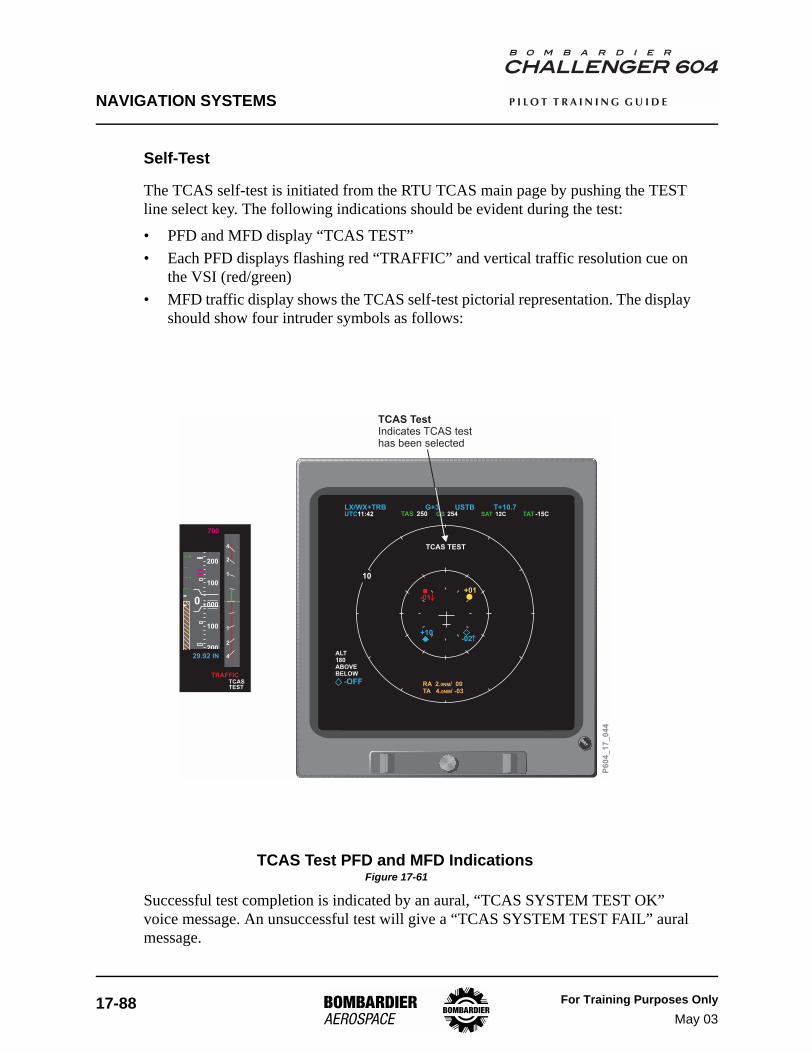
NAVIGATION SYSTEMS
17-88 For Training Purposes OnlyMay 03
P I L O T T R A I N I N G G U I D E
Self-Test
The TCAS self-test is initiated from the RTU TCAS main page by pushing the TEST line select key. The following indications should be evident during the test:
• PFD and MFD display “TCAS TEST”• Each PFD displays flashing red “TRAFFIC” and vertical traffic resolution cue on
the VSI (red/green)• MFD traffic display shows the TCAS self-test pictorial representation. The display
should show four intruder symbols as follows:
TCAS Test PFD and MFD Indications Figure 17-61
Successful test completion is indicated by an aural, “TCAS SYSTEM TEST OK” voice message. An unsuccessful test will give a “TCAS SYSTEM TEST FAIL” aural message.
BRT
T+10.7250 SAT 12C
10
LX/WX+TRBTAS 254
USTBUTC11:42 GS TAT-15C
FMS2YUL
G+3
+10
+01
TCAS TEST
RA 2. / 00TA 4. / -03
0NM
0NM
ABOVEBELOW
ALT180
-OFF
-02
-01
TCAS TestIndicates TCAS testhas been selected
P6
04
_1
7_
04
4000
100
200
100
200
29.92 IN
1
2
4
1
2
4
0
TRAFFICTCASTEST
2700
2
1

NAVIGATION SYSTEMS
For Training Purposes OnlyMay 03
17-89
P I L O T T R A I N I N G G U I D E
Global Positioning System (GPS)
DescriptionThe GPS is a space-based navigation system that provides highly accurate three-dimensional position, velocity and time information to ground or aircraft receivers.
The GPS is a sensor used by the flight management system to compute an accurate position. All GPS data is accessed through the FMS CDU.
The GPS has three main segments:
• space segment• control segment (ground)• user segment
Space SegmentThe space segment of the GPS is made up of 24 NAVSTAR satellites. There are 21 operational satellites at all times and three are spares. The satellites:
• are in a 10,900-mile-high orbit• are in six orbital planes with 3 to 4 satellites in each plane• have a 12-hour orbit• are spaced to provide a minimum of 4 satellites in view at all times• have atomic clocks and transmit on two coded frequencies
Control SegmentThe control segment monitors the space segment and adjusts the orbits when operationally required. It includes five ground stations around the world. One is the master control station and the others are monitor stations.
The monitor stations passively track all satellites in view and acquire range data from them. This data is forwarded to the master control station. The master control station uses the data from the monitor stations to estimate satellite orbit and clock data. This information is transmitted to the satellites and down to the users as a navigation message.
User SegmentThe FMS uses the signal from the GPS satellites as a navigation sensor to upgrade its own position. A minimum of three satellites is required for two-dimensional calculations and four satellites are required for three-dimensional calculations.

NAVIGATION SYSTEMS
17-90 For Training Purposes OnlyMay 03
P I L O T T R A I N I N G G U I D E
Components and Operation
GPS Receivers
Dual GPS receivers are installed in the Challenger 604 (GPS 1 and GPS 2). The GPS receivers process signals from the orbiting constellation of GPS satellites to determine geographic position. Each of the GPS receivers is capable of receiving up to 12 satellites. Tuning is fully automatic, and does not require any pilot input/action.
GPS 1 is powered by DC Bus 1, and GPS 2 is powered by DC Bus 2.
GPS Sensors and Navigation
The flight management system (FMS) is the interface between the GPS receivers and the aircraft navigation systems. GPS position information is supplied to each FMS by the on-side GPS receiver (GPS 1 supplies FMS 1, and GPS 2 supplies FMS 2). The FMS then calculates the integrated navigation solution (FMS position) using a combination of GPS, DME/DME, VOR/DME, and IRS sensor information.
In the event that on-side GPS information is not available, the FMS will automatically use cross-side information, and display the GPS REVERTED message on the FMS CDU.
GPS RAIM
GPS Receiver Autonomous Integrity Monitoring (RAIM) is used to assure that the GPS position information meets the required accuracy:
• 4 NM oceanic/remote• 2 NM en route• 1 NM terminal• 0.3 NM final approach
The current RAIM accuracy limit and measured accuracy limit are displayed on the MFD LRN STATUS page 2/2. The measured accuracy limit indicates the maximum estimated error based on measurement inconsistency. Unless an error is detected by RAIM, this value is always less than the RAIM accuracy limit.
When an error is detected, it is annunciated on the MFD LRN STATUS page 2/2. If the detected error cannot be predicted to be less than the required integrity threshold, GPS is removed from the navigation solution.
If no error is detected by RAIM, the probable GPS error is shown. This is a statistical number based on normal satellite error characteristics.

NAVIGATION SYSTEMS
For Training Purposes OnlyMay 03
17-91
P I L O T T R A I N I N G G U I D E
MFD LRN STATUS (Page 2/2) Figure 17-62
P6
04
_1
7_
09
2
LRN STATUS
SENSOR POSITION TRK/SPD
2/2
GPS 1
GPS 2
N33°40,87 W116°59,50 071°/405
MODE: NAVRAIM ACCURACY LIMIT:MEAS ACCURACY LIMIT:PROBABLE ERROR:
SATELLITES: 80.10 NM0.10 NM0.05 NM
0000000
GPS 2 N33°40,87 W116°59,50 071°/405
MODE: NAVRAIM ACCURACY LIMIT:MEAS ACCURACY LIMIT:PROBABLE ERROR:
SATELLITES: 80.10 NM0.10 NM0.05 NM
0000000
LRN STATUS
SENSOR POSITION TRK/SPD
2/2
GPS 1
GPS 2
N53°43,30 W000°12,30 315°/254
MODE: NAVRAIM ACCURACY LIMIT:MEAS ACCURACY LIMIT:PROBABLE ERROR:
SATELLITES:120.41 NM0.23 NM0.04 NM
000000
GPS 2 N53°43,30 W000°12,30 315°/254
MODE: NAVRAIM ACCURACY LIMIT:MEAS ACCURACY LIMIT:RAIM DETECTED ERROR
SATELLITES: 70.41 NM0.46 NM
00000000.05 NM
NORMAL RAIM INDICATIONS RAIM DETECTED ERROR ON GPS 2
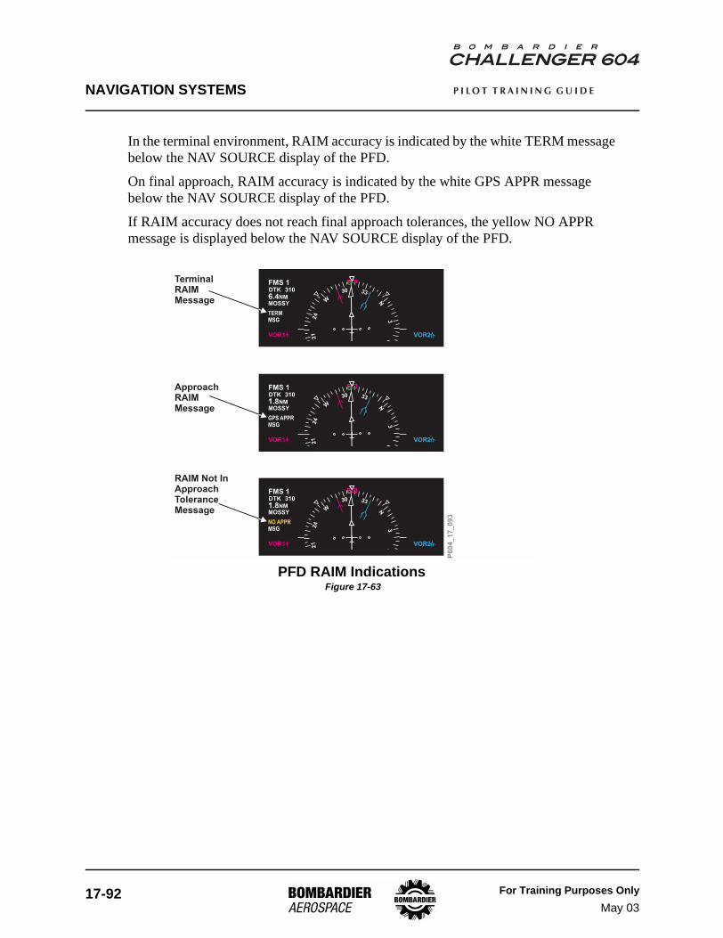
NAVIGATION SYSTEMS
17-92 For Training Purposes OnlyMay 03
P I L O T T R A I N I N G G U I D E
In the terminal environment, RAIM accuracy is indicated by the white TERM message below the NAV SOURCE display of the PFD.
On final approach, RAIM accuracy is indicated by the white GPS APPR message below the NAV SOURCE display of the PFD.
If RAIM accuracy does not reach final approach tolerances, the yellow NO APPR message is displayed below the NAV SOURCE display of the PFD.
PFD RAIM Indications Figure 17-63
N
3330
W
24
21
63
VOR1
FMS 1DTK
1.8NMMOSSY
310
VOR2
NO APPRMSG
P6
04
_1
7_
09
3
RAIM Not InApproachToleranceMessage
N
3330
W
24
21
63
VOR1
FMS 1DTK
1.8NMMOSSY
310
VOR2
GPS APPRMSG
N
3330
W
24
21
63
VOR1
FMS 1DTK
6.4NMMOSSY
310
VOR2
TERMMSG
TerminalRAIMMessage
ApproachRAIMMessage

NAVIGATION SYSTEMS
For Training Purposes OnlyMay 03
17-93
P I L O T T R A I N I N G G U I D E
For a complete listing of GPS and RAIM messages, see the “Collins FMS-6000 for the Challenger 604” Pilot’s Guide.
FMS CDU RAIM Message Figure 17-64
P6
04
_1
7_
09
1
MSG EXEC
POS BRT
TITLE LINE 1/3
PRED RAIM
CYYZ
CYOW
RW06L
ACTIVATE>
CYUL
GPS 2 <ENABLED>
RJ001
DIRECT
<ROUTE MENU
DEST
ALTN
ORIG RWY
ETA
R1
ORIGIN
ROUTE
FLT NO
VIA
DEST
L
SEC FPLN 1/3
[ ]
<SEC LEGSATC 1
YULTO
ATC 2SEC PERF>
AVAIL
NO GPS RAIM
FMS-CDU RAIM Message

NAVIGATION SYSTEMS
17-94 For Training Purposes OnlyMay 03
P I L O T T R A I N I N G G U I D E
Controls and Indicators
FMS-GPS Control Page
The GPS control page allows the pilot to monitor the FMS aircraft position in relation to the GPS. The position differential (POS DIFF) is shown in direction and magnitude from the FMS position.
To alternately enable or disable use of a specific GPS sensor, push the left side line-select key of that sensor. Enabled sensors show in large green font, and disabled sensors show in small white font.
The DEST and ETA entries are those of the active flight plan. You can manually enter changes to see if RAIM is available for other destinations and/or arrival times.
Satellite Deselect
Individual satellites can be deselected from use by entering the identifier for the satellite in the FMS. This function would be used if the satellite is NOTAMed under test. When deselected, the FMS ignores the data from the satellite. Deselected satellites are not included in the predicted RAIM computations.
FMS GPS Control Page Figure 17-65
P6
04
_1
7_
09
0
MSG EXEC
POS BRT
TITLE LINE 1/3
>
>
>
>
GPS 1 <ENABLED>
GPS 2 <ENABLED>
114.85
18 21 5 13
CYUL
R
R
E
ETA
R1
COM 1
RCL 1
NAV 1
SAT DESELECT
DEST
L
FMS1 GPS CONTROL 1/5
[ ]
<INDEXATC 1
016° / 0.0
114.85
AUTO/MAN
23:59
POS DIFF
RCL 2
NAV 2
NAV 2
1441ATC 2
>
AVAILPRED RAIM
016° / 0.0

NAVIGATION SYSTEMS
For Training Purposes OnlyMay 03
17-95
P I L O T T R A I N I N G G U I D E
Flight Management System (FMS)
DescriptionA dual flight management system (FMS) provides integrated cockpit and flight management functions. Each flight management system (FMS 1 and FMS 2) is composed of a Control Display Unit (CDU) in the cockpit and a Flight Management Computer (FMC) in the underfloor avionics equipment bay. A single Data Base Unit (DBU) allows data to be uploaded or downloaded to all of the FMCs. A third flight management system (FMS 3) may be installed as a customer option.
The FMS cockpit management functions include:
• Navigation sensor control• Radio tuning• Multifunction display (MFD) control menus• Navigation database management• Control and management of the data loader• Management of the data interface with external systems (AFIS)
Flight management functions include:
• Continuous calculation of the integrated navigation solution• Flight plan inputs by the crew• Lateral flight plan point-to-point navigation• Vertical navigation• Performance calculation• Lateral/vertical steering commands to the flight control system
The third FMS, if installed, is defined as a “hot spare” and is fully functional when selected.
For a comprehensive description of FMS functions and operation, refer to the “Collins FMS-6000 for the Challenger 604” Pilot’s Guide.
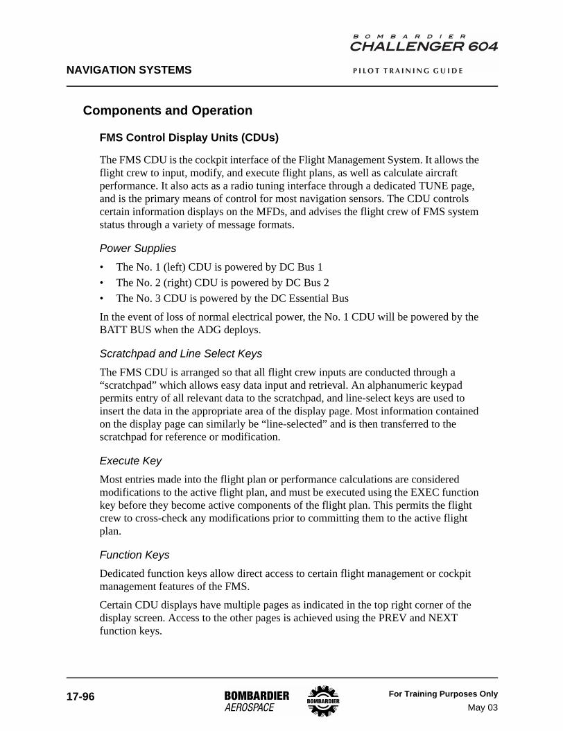
NAVIGATION SYSTEMS
17-96 For Training Purposes OnlyMay 03
P I L O T T R A I N I N G G U I D E
Components and Operation
FMS Control Display Units (CDUs)
The FMS CDU is the cockpit interface of the Flight Management System. It allows the flight crew to input, modify, and execute flight plans, as well as calculate aircraft performance. It also acts as a radio tuning interface through a dedicated TUNE page, and is the primary means of control for most navigation sensors. The CDU controls certain information displays on the MFDs, and advises the flight crew of FMS system status through a variety of message formats.
Power Supplies• The No. 1 (left) CDU is powered by DC Bus 1• The No. 2 (right) CDU is powered by DC Bus 2• The No. 3 CDU is powered by the DC Essential Bus
In the event of loss of normal electrical power, the No. 1 CDU will be powered by the BATT BUS when the ADG deploys.
Scratchpad and Line Select KeysThe FMS CDU is arranged so that all flight crew inputs are conducted through a “scratchpad” which allows easy data input and retrieval. An alphanumeric keypad permits entry of all relevant data to the scratchpad, and line-select keys are used to insert the data in the appropriate area of the display page. Most information contained on the display page can similarly be “line-selected” and is then transferred to the scratchpad for reference or modification.
Execute KeyMost entries made into the flight plan or performance calculations are considered modifications to the active flight plan, and must be executed using the EXEC function key before they become active components of the flight plan. This permits the flight crew to cross-check any modifications prior to committing them to the active flight plan.
Function KeysDedicated function keys allow direct access to certain flight management or cockpit management features of the FMS.
Certain CDU displays have multiple pages as indicated in the top right corner of the display screen. Access to the other pages is achieved using the PREV and NEXT function keys.

NAVIGATION SYSTEMS
For Training Purposes OnlyMay 03
17-97
P I L O T T R A I N I N G G U I D E
MFD Function KeysThree function keys relate specifically to MFD displays. The MFD DATA and MFD MENU keys control the type of information available on the MFD. The MFD ADV key allows access to multiple pages of MFD information. When the PLAN MAP format of the MFD is in use, the MFD ADV key allows the flight crew to view the waypoints of their flight plan.
FMS Control Display Unit (CDU) Figure 17-66
MSG EXEC
DIR LEGSDEPARR
FPLN IDX TUNE
MFDDATA
MFDMENU
MFDADV
PERF PREV NEXT
A
G1 2 3
M
S
Y
B C
SP
D
DEL
E F
H
N
T
Z
I
O
U
J
P
V
K
Q
W
/
L
R
X
CLR
4
7
.
5
8
O
6
9
+/-
POS BRT
TITLE LINE 1/3
>
>
>
23MAY02
>
POS INIT>
WORLD
23MAY02 23JUN02
25APR02 22MAY02
12:11
SCID 832-4117-034
<INDEX
R
R
E
DATE
R
R
NAV DATA
ACTIVE DATA BASE
SEC DATA BASE
UTC
PROGRAM
L
STATUS 1/2
[ ]SCRATCHPAD LINEANNUNCIATIONMSG EXEC
Line Select Keys Line Select Keys
Scratchpad LineMessageAnnunciation Line
Execute Key
MFD Function Keys
Message Key
FMS 3
FMS 1 FMS 2
P6
04
_1
7_
04
7
Function Keys
Alphanumeric Keys

NAVIGATION SYSTEMS
17-98 For Training Purposes OnlyMay 03
P I L O T T R A I N I N G G U I D E
Flight Management Computers (FMCs)
The flight management computers are installed in the Integrated Avionics Processor System (IAPS). The FMCs receive flight crew inputs from the CDU, and perform all the flight management and cockpit management functions. Each FMC contains a navigation database, which it uses to execute the active flight plan.
Integrated Navigation SolutionThe integrated navigation solution is the FMS-calculated position of the aircraft in latitude and longitude. The FMCs receive data from all aircraft navigation sensors, and continuously calculate the integrated navigation solution. GPS is normally the highest priority sensor used in this position calculation, but a combination of DME/DME, VOR/DME, and IRS information is also used according to predetermined blending algorithms. The FMC rejects sensor data that is not valid, and advises the flight crew of position determination errors through the CDU message system.
Flight Plan TrackingBy comparing the integrated navigation solution to the navigation database and the active flight plan, the FMC calculates and displays the aircraft's position relative to the flight plan routing, and issues steering commands to the flight control computers to track the lateral and vertical components of the active flight plan.
Data Base Unit (DBU)
The Data Base Unit (DBU) is a panel-mounted data loader with a disk drive that is used with the FMS system and the maintenance diagnostic computer. The FMS system uses the DBU to load database updates from diskettes into the FMS computers. The Integrated Avionics Processor System (IAPS) maintenance diagnostic computer uses the DBU to upload maintenance tables from diskette or download maintenance data files to diskette. High-density and double-density 3-1/2 inch diskettes are acceptable. The unit has a “drive in-use” indicator and a disk eject button.
The navigation database is loaded into each FMC individually through the DBU. Flight plans and waypoints may also be loaded or stored on disk through the DBU.

NAVIGATION SYSTEMS
For Training Purposes OnlyMay 03
17-99
P I L O T T R A I N I N G G U I D E
Data Base Unit Figure 17-67
DBUUsed to revise FMS NAV data base upload /download data from AFIS maintenancediagnostic computer.
P6
04
_1
7_
04
6

NAVIGATION SYSTEMS
17-100 For Training Purposes OnlyMay 03
P I L O T T R A I N I N G G U I D E
Synchronized / Independent Operation
Dual-FMS systems have provision for operation in synchronized (SYNC) or independent (INDEP) modes. By default, dual-FMS airplanes power up in SYNC, and triple-FMS airplanes power up in INDEP mode.
In the triple-FMS configuration, the flight crew decides which two FMSs to synchronize. FMS 3 is selected using the FMS reversionary selector switch (see Figure 17-69). SYNC / INDEP mode selections are made on the FMS CONTROL page of the CDU.
When two FMSs are synchronized, they share the following parameters:
• Flight Plan edits• Performance initialization• Leg sequencing• Active database selection• Fix entries• Deselection of navaids• Performance mode selection• MAG / TRU display mode• Thrust management
Parameters that are not synchronized include:
• FMC position initialization• Selection of left / right sensors
When the FMSs are operated in INDEP mode, all parameters must be manually entered in each FMS.
For additional information about SYNC / INDEP operation, see the “Collins FMS-6000 for the Challenger 604” Pilot’s Guide.

NAVIGATION SYSTEMS
For Training Purposes OnlyMay 03
17-101
P I L O T T R A I N I N G G U I D E
Controls and Indicators
FMS Tune Inhibit
The FMS may be inhibited from tuning the radios by selection of the FMS TUNE INHIB switch/light located on the Reversionary/Inhibit panel.
FMS TUNE INHIB Switch/Light Figure 17-68
P6
04
_1
7_
05
0
INHIBIT PUSH
1-RTU-2 FMS TUNE
1 2
AFCSSEL
STBY
1 2
ATCSEL
FMSTUNEINHIB
RTU 1INHIB
RTU 2INHIB
1 21 2
FMS Tune InhibitSwitch/Light
FMS TUNE INHIB Light
- Disables radio tuning fromFMS CDU
Illuminates when FMS auto tune inhibitselected

NAVIGATION SYSTEMS
17-102 For Training Purposes OnlyMay 03
P I L O T T R A I N I N G G U I D E
FMS 3 Reversionary Selector
FMS 3 may be selected using the FMS 3 reversionary selector switch on the center pedestal. FMS 3 replaces FMS 1 or FMS 2 when the rotary selector switch is moved to the position 1 or 2 respectively.
FMS 3 Reversionary Selector Figure 17-69
P6
04
_1
7_
09
7
L IRS R IRS FMS3
1 2NORM
1 2NORM ALTN ALTNNORM

NAVIGATION SYSTEMS
For Training Purposes OnlyMay 03
17-103
P I L O T T R A I N I N G G U I D E
FMS Message Displays
The FMS messages are displayed in several locations. Typically, a message remains displayed as long as the condition that generated the message persists. For a complete description of messages and message categories, see the “Collins FMS-6000 for the Challenger 604” Pilot’s Guide.
CDU MessagesMessages may appear in the scratchpad or in the message line immediately below the scratchpad. Selection of the MSG function key cycles the CDU display to a dedicated message page, where new and old messages may be reviewed.
CDU Message Display Figure 17-70
P6
04
_1
7_
09
4
MSG EXEC
POS BRT
TITLE LINE 1/3
PRED RAIM
NONE
GPS NOT AVAILABLE
FMS NAV INVALID
FMS INDEPENDENT OP
XTALK FAILETA
R1
DEST
L
MESSAGES 1/1
[ ]
INITIALIZE POSITIONATC 1 ATC 2
AVAIL
MSG
NEW MESSAGES
OLD MESSAGES
MSG EXEC
POS BRT
AUTO/INHIBIT
>
>
>
RW06R
YUL
YOW
373.0
SEQUENCE
R
E
R
R1
COM 1
331°
ADF 1
L
ACT LEGS 1/1
[ ]
<RWY UPDATE
AUTO/MAN
373.0
NAV 2
ADF 2
LEG WIND>
279°
13NM
INVALID DELETE
MSG
82NM
AUTO INHIBIT/
AUTO INHIBIT/
CDU Messages Line Scratchpad Message
CDU MESSAGES PAGE

NAVIGATION SYSTEMS
17-104 For Training Purposes OnlyJan 04
P I L O T T R A I N I N G G U I D E
PFD MessagesFMS messages also appear on the PFD, immediately under the NAV SOURCE display (when FMS is the NAV SOURCE). Additionally, certain PFD messages may be displayed in the center of the HSI.
PFD Message Display Figure 17-71
N33
S15
12
E6
3
N33
S15
12
E6
3
20
10
10
20
2R
T
160
140
120
100
800
700
600
500
400
RWY
ADF1
29.96 IN
1/2BNK LNV1 DR VGP
AP
1
2
4
1
2
4
0.7
128
1
840MDA
M.452
FMS1DTK
3.8NMRW07
GPS APPRMSG
072
LOC1
25
ADF2
ALTS PATH GS900
HDG 072
1200FT
25
BRT
PRIMARY FLIGHT DISPLAY
NO FLIGHT PLANFMS that is selected as NAV source hasno active flight plan
A1 and A2 FMS Messages- O
1 MSGs will flash for 5 secs t remain on.- A2 MSGs two types:1- Clearable using “MSG” key.2- Non-clearable until condition(s) clear.
nly highest priority MSG displayed if morethan one active.- Only displayed if FMS is the NAV sourceshown on that PFD. MSGs will clear if causeceases to exist.- A hen
P6
04
_1
7_
04
8
FMS1DTK
3.8NMRW07
GPS APPRMSG
072
NO FLIGHT PLAN

NAVIGATION SYSTEMS
For Training Purposes OnlyMay 03
17-105
P I L O T T R A I N I N G G U I D E
MFD MessagesFMS messages may be displayed on the lower portion of the MFD display area.
MFD Message Display Figure 17-72
WX G+1 USTB T+10.7TAS 0 0
RW06RYULYOWCYUL
0NM
95NM186NM
14NM::
0 050 071 33
:::::
DME2
– – – –
USTB T-4.5UTC12:03 GS SAT-15C TAT-0C
40
80
FMS NAV INVALID
MAP
P6
04
_1
7_
09
6

NAVIGATION SYSTEMS
17-106 For Training Purposes OnlyMay 03
P I L O T T R A I N I N G G U I D E
FMS Color Conventions
The FMS color conventions are outlined in the following table. The EFIS FMS colors have been included for reference only.
COLOR FMS CDU USE EFIS USE (REFERENCE ONLY)
RED Not used. Warnings.
YELLOW Cautions usually requiring timely pilot intervention. Cautions.
GREEN Active selections VNAV data on legs page. Safe/normal operation altitudes on map.
CYAN Secondary information (e.g. from waypoint, page titles, and route plan legs).
Legends, pilot-selected values, secondary map data.
MAGENTA Active leg (“to waypoint”). “To waypoint”, fly-to-reference flight director, airspeed bug, preselect altitude.
WHITEPrimary information (e.g. flight plan data, down track waypoints, and FPLN and legs ACT or MOD state).
Reference symbols, scales NAV MAP, alternate source sensor, on-side FMS, AFDS armed modes.
FMS Color Conventions Table Table 17-14


![, SYLVIE CHAMBON , ANAND P. SANTHANAM · XML Template (2008) [23.9.2008–3:12pm] [281–298] {TANDF REV}TCAS/TCAS I 13 05/TCAS A 343366.3d (TCAS)[Revised Proof] impact on improving](https://static.fdocuments.net/doc/165x107/5b1440a87f8b9a3e7c8c07bc/-sylvie-chambon-anand-p-santhanam-xml-template-2008-2392008312pm.jpg)