PILES TABLE OF CONTENTS - Virginia Department of ... · PDF file23.01-12 Steel H-Pile Design...
20
PILES TABLE OF CONTENTS PART 2 DATE: 30Jan2018 SHEET 1 of 1 FILE NO. 23.TOC CHAPTER 23 – PILES TABLE OF CONTENTS FILE NO. TITLE DATE TABLE OF CONTENTS 23.TOC Table of Contents ........................................................................... 30Jan2018 23.00 Introduction .................................................................................... 30Jan2018 DESIGN GUIDE FOR LATERALLY UNSUPPORTED PILES 23.01-1 Notes and Definitions ..................................................................... 30Jan2018 23.01-2 Design Criteria ............................................................................... 30Jan2018 23.01-3 Design Criteria ............................................................................... 30Jan2018 23.01-4 Coarse Grain Soil Example............................................................ 30Jan2018 23.01-5 Cohesive Soil Example .................................................................. 30Jan2018 23.01-6 Layered Soil Example .................................................................... 30Jan2018 23.01-7 Layered Soil Example .................................................................... 30Jan2018 23.01-8 Steel H-Pile Design Criteria ........................................................... 30Jan2018 23.01-9 Steel H-Pile Design Criteria ........................................................... 30Jan2018 23.01-10 Properties for Designing Steel H-Piles .......................................... 30Jan2018 23.01-11 Steel H-Pile Design Example ......................................................... 30Jan2018 23.01-12 Steel H-Pile Design Example ......................................................... 30Jan2018 23.01-13 Prestressed Concrete Pile Design Criteria .................................... 30Jan2018 23.01-14 Prestressed Concrete Pile Design Example .................................. 30Jan2018 LATERAL LOADED PILE ANALYSIS FOR POINT OF FIXITY 23.02-1 Design Procedure .......................................................................... 30Jan2018 23.02-2 Design Assumptions and Results .................................................. 30Jan2018 23.02-3 L-Pile Results for Scour Condition ................................................. 30Jan2018 23.02-4 L-Pile Results for Non-Scour Condition ......................................... 30Jan2018
Transcript of PILES TABLE OF CONTENTS - Virginia Department of ... · PDF file23.01-12 Steel H-Pile Design...

PILES TABLE OF CONTENTS
PART 2 DATE: 30Jan2018 SHEET 1 of 1
FILE NO. 23.TOC
CHAPTER 23 – PILES
TABLE OF CONTENTS
FILE NO. TITLE DATE
TABLE OF CONTENTS
23.TOC Table of Contents ........................................................................... 30Jan2018 23.00 Introduction .................................................................................... 30Jan2018
DESIGN GUIDE FOR LATERALLY UNSUPPORTED PILES
23.01-1 Notes and Definitions ..................................................................... 30Jan2018 23.01-2 Design Criteria ............................................................................... 30Jan2018 23.01-3 Design Criteria ............................................................................... 30Jan2018 23.01-4 Coarse Grain Soil Example ............................................................ 30Jan2018 23.01-5 Cohesive Soil Example .................................................................. 30Jan2018 23.01-6 Layered Soil Example .................................................................... 30Jan2018 23.01-7 Layered Soil Example .................................................................... 30Jan2018 23.01-8 Steel H-Pile Design Criteria ........................................................... 30Jan2018 23.01-9 Steel H-Pile Design Criteria ........................................................... 30Jan2018 23.01-10 Properties for Designing Steel H-Piles .......................................... 30Jan2018 23.01-11 Steel H-Pile Design Example ......................................................... 30Jan2018 23.01-12 Steel H-Pile Design Example ......................................................... 30Jan2018 23.01-13 Prestressed Concrete Pile Design Criteria .................................... 30Jan2018 23.01-14 Prestressed Concrete Pile Design Example .................................. 30Jan2018
LATERAL LOADED PILE ANALYSIS FOR POINT OF FIXITY
23.02-1 Design Procedure .......................................................................... 30Jan2018 23.02-2 Design Assumptions and Results .................................................. 30Jan2018 23.02-3 L-Pile Results for Scour Condition ................................................. 30Jan2018 23.02-4 L-Pile Results for Non-Scour Condition ......................................... 30Jan2018

PILES INTRODUCTION
PART 2 DATE: 30Jan2018 SHEET 1 of 1
FILE NO. 23.00
INTRODUCTION
It is the intent of this chapter to establish the guidelines and specific requirements of the Structure and Bridge Division for the design and analysis of laterally unsupported piles, specifically relating to the use of steel H-piles and prestressed concrete piles subjected to scour and biaxial bending. It provides design procedures and examples for determining the point of fixity, effective length factor, ‘K’, and the structural capacity of these piles. This chapter also provides a bridge specific example for determining the point of fixity for a laterally loaded pile for use in Elastic Frame Analysis using commercially available software for non-linear analysis of piles, L-Pile. Point of fixities for both the existing or final profile and the scoured condition may need to be determined. Shorter distances to points of fixities based on existing or final profile (non-scoured) can control design in exterior spans of large units and affect bridge behavior. Example calculations in this chapter show for scoured conditions, but non-scoured is similar. References to the AASHTO LRFD specifications in this chapter refer to the AASHTO LRFD Bridge Design Specifications, 7th Edition, 2014, and VDOT Modifications (current IIM-S&B-80). The practices and requirements set forth herein are intended to supplement or clarify the requirements of the AASHTO LRFD specifications, and to provide additional information to assist the designer. In the event of conflicts(s) between the practices and requirements set forth herein and those contained in the AASHTO LRFD specifications, the more stringent requirements shall govern. Standards for prestressed concrete piles are located in the Manual of the Structure and Bridge Division, Part 3.
Standard BPP-1 (Carbon Steel Strands) Standard BPP-2 (Stainless Steel Strands) Standard BPP-3 (Carbon Fiber Reinforced Polymer [CFRP] Strands)
It is expected that the users of this chapter will adhere to the guidelines and requirements stated herein. Major changes and/or additions to the past office practice (Part 2 of this manual) are as follows:
1. Updated calculations for design of steel H-piles to reflect AASHTO LFRD Specifications from previously referenced AASHTO Standard Specifications.
2. Added example including as-built bridge data for a laterally loaded pile analysis using L-
Pile for use in Elastic Frame Analysis. NOTE: Due to various restrictions on placing files in this manual onto the Internet, portions of the drawings shown do not necessarily reflect the correct line weights, line types, fonts, arrowheads, etc. Wherever discrepancies occur, the written text shall take precedence over any of the drawn views.
PILES DESIGN GUIDE FOR LATERALLY UNSUPPORTED PILES
GENERAL INFORMATION AND DEFINITIONS
PART 2
DATE: 30Jan2018
SHEET 1 of 14
FILE NO. 23.01-1
GENERAL INFORMATION: For the 100 year storm, the factored capacity is checked using the AASHTO Strength and Service Load Combinations and Load Factors. For the 500 year storm, the factored capacity is checked using the AASHTO Extreme Event Load Combinations and Load Factors. AASHTO Load Combinations and Load Factors shall be in accordance with Table 3.4.1-1.
This guide does not indicate how to determine the axial loads and moments to be used in the formulas for analysis of piles. Because the piles are not laterally restrained, sideway is not prevented; therefore, it is recommended that the designer utilize appropriate structural modeling software, such as RCPier, to determine the applied axial loads and moments.
DEFINITIONS:
b Pilewidthindirectionofbending ft
D Pileembedmentlengthintoground ft
D Depthofassumedpointoffixity ft
N StandardPenetrationTest STP Blowcount
c Cohesivestrength 0.125 ∙ N ksf
S undrainedshearstrengthofclays c ksf
n rateofincreaseofsoilmoduluswithdepthforsandsasspecifiedinTableC10.4.6.3 2
E Modulusofelasticityofconcrete AASHTOC5.4.2.4
586,029 ksf forf c 5,000psi
641,962 ksf forf c 6,000psi
E Modulusofelasticityofpile ksf
E soilmodulusforclays 0.465 ∙ S ksi (AASHTO C10.7.3.13.4)
A Grossareaofpile in
I MomentofInteriaofpile ft
S Elasticsectionmodulusofpile in
Z Plasticsectionmodulusofpile in
r radiusofgyrationofpile in
L Unsupportedlengthofpile ft
δ deflectionofpileincoarsegrainsoils; ifδ ∙ D 4, thenpinnedend; otherwisefixedend
β deflectionofpileincohesivesoils; ifβ ∙ D 2.25, thenpinnedends; otherwisefixedend

PILES DESIGN GUIDE FOR LATERALLY UNSUPPORTED PILES
DESIGN CRITERIA
PART 2
DATE: 30Jan2018
SHEET 2 of 14
FILE NO. 23.01-2
DESIGN CRITERIA: POINT OF FIXITY FOR FREE STANDING PILE DESIGN CRITERIA: Point of fixity for both the existing or final profile and the scoured condition may need to be determined. EFFECTIVE LENGTH FACTOR – K: Top
Bottom
Top: R_free & T_free R_fixed & T_free R_free & T_fixed
Bottom: R_fixed & T_fixed R_fixed & T_fixed R_fixed & T_fixed
K = 2.1 K = 1.2 K = 0.8
Pier bent on single rowof piles with load appliedin longitudinal direction
Pier bent on piles with load applied in transverse direction
Integral abutment on piles with load applied in longitudinal direction
End Conditions: R = Rotation; T = Translation
D must be ≥ 3D for fixity to be assumed

PILES DESIGN GUIDE FOR LATERALLY UNSUPPORTED PILES
DESIGN CRITERIA
PART 2
DATE: 30Jan2018
SHEET 3 of 14
FILE NO. 23.01-3
DESIGN CRITERIA (Cont’d): Table 1 – Rate of Increase of Soil Modulus with Depth, (ksi/ft)
for Sand (AASHTO Table C10.4.6.3-2)
Consistency Dry or Moist Submerged
Loose 0.417 0.208
Medium 1.11 0.556
Dense 2.78 1.39 Table 2 – Relationship between unconfined compressive strength, standard penetration
resistance, and unit weight for cohesive soils (Teng, 1962)
SHEAR STRENGTH OF COHESIVE SOILS
Consistency Very Soft
Soft Medium Stiff Very Stiff
Hard
qu = Unconfined compressive strength, lb/ft2
Standard penetration resistance N = No. of blows per ft. Unit weight, pcf (saturated)
110 - 130
130+
Cohesive (c) = ½ unconfined compression strength Table 3 – Relationship between relative density, standard penetration resistance, angle of
internal friction and unit weight for cohesive soils (Teng, 1962)
RELATIVE DENSITY OF GRANULAR SOILS
Compactness Very
Loose Loose Medium Dense
Very Dense
Relative density Standard penetration resistance, N = No. of blows per foot Angle of internal friction ∅ (degrees) * Unit weight, pcf Moist Submerged
<100 <60
95-125 55-65
110-130 60-70
110-140 65-85
>130 >75
*Highly dependent on gradation
0 500 1000 2000 4000 8000
0 2 4 8 16 32
100 - 120 120 - 140
28 30 36 41
0 4 10 30 50
0 15% 35% 65% 85% 100%

PILES DESIGN GUIDE FOR LATERALLY UNSUPPORTED PILES
COARSE GRAIN SOIL EXAMPLE
PART 2
DATE: 30Jan2018
SHEET 4 of 14
FILE NO. 23.01-4
POINT OF FIXITY FOR FREE STANDING PILE – COARSE GRAIN SOIL EXAMPLE: Coarse grain soil, medium relative density (N = 27 blows/ft), above ground water. HP12x53 subject to biaxial bending.
Pile Length 60ft Scour Depth 10ft D 50ft
I 393in I 127in E 29,000ksi
r 5.03in r 2.86in Based on N = 27, a medium-dense soil is assumed. Use Tables 1 and 3 on File No. 23.01-3 to determine the value of nh by performing linear interpolation between a medium soil (N = 20, nh = 1.11), and a dense soil (N = 50, nh = 2.78); n 1.5ksi/ft
E I29,000 393
14479,146kip ∙ ft E I
29,000 127144
25,576kip ∙ ft
D 1.8E In
1.879,146
1.5x144inft
5.86 ft (AASHTO C10.7.3.13.4-2)
D 1.8E I
n1.8
25,576
1.5x144inft
4.68 ft (AASHTO C10.7.3.13.4-2)
δnE I
0.3071ft
δ ∙ D 15.35 4 ∴ fixed end
δnE I
0.3851ft δ ∙ D 19.24 4 ∴ fixed end
DD
505.86
8.53 3 ∴ fixed end
DD
504.68
10.69 3 ∴ fixed end
ScourDepth D 10ft 5.86 ft 15.86 ft
ScourDepth D 10ft 4.68 ft 14.68 ft
Single row of piles with fixed ends in x-direction: Where: Unsupported length of pile
K Effective length factor
R Radius of gyration
K 2.1 Kr
2.1 15.86x 12inft
5.0379.47
Single row of piles with fixed ends in y-direction:
K 1.2 K
r
1.2 14.68x 12inft
2.8673.9

PILES DESIGN GUIDE FOR LATERALLY UNSUPPORTED PILES
COHESIVE SOIL EXAMPLE
PART 2
DATE: 30Jan2018
SHEET 5 of 14
FILE NO. 23.01-5
POINT OF FIXITY FOR FREE STANDING PILE – COHESIVE SOIL EXAMPLE: Cohesive soil, blow count N 12blows/ft
Pile Length: 60ft Scour Depth 10ft D 50ft HP12x53 subject to biaxial bending.
I 393in I 127in b 12.045in E 29,000ksi r 5.03in r 2.86in b 11.78in
c 0.125Nksf 1.5ksf S c 1.5ksf E 0.465 ∙ S 0.698ksi Note: Soil modulus is reduced for pile spacing < 8 times the pile width, see Article C10.7.3.13.4. (For this example, since a specific pile spacing is not provided, no reduction is assumed.)
D 1.4E IE
1.429000 393
0.698x
1
12inft
7.42 ft (AASHTO C10.7.3.13.4-1)
D 1.4E I
E1.4
29000 1270.698
x1
12inft
5.59 ft (AASHTO C10.7.3.13.4-1)
βEE I
x12inft
0.1891ft
β ∙ D 9.44 2.25 ∴ fixed end
βEE I
x12inft
0.251ft
β ∙ D 12.52 2.25 ∴ fixed end
DD
507.42
6.74 3 ∴ fixed end
DD
505.59
8.94 3 ∴ fixed end
ScourDepth D 10ft 7.42 ft 17.42 ft
ScourDepth D 10ft 5.59 ft 15.59 ft
Single row of piles with fixed ends in x-direction: Where: Unsupported length of pile
K Effective length factor
R Radius of gyration
K 2.1 Kr
2.1 17.42 x 12inft
5.0387.26
Single row of piles with fixed ends in y-direction:
K 1.2 K
r
1.2 15.59 x 12inft
2.8678.51

PILES DESIGN GUIDE FOR LATERALLY UNSUPPORTED PILES
LAYERED SOIL EXAMPLE
PART 2
DATE: 30Jan2018
SHEET 6 of 14
FILE NO. 23.01-6
POINT OF FIXITY FOR FREE STANDING PILE – LAYERED SOIL EXAMPLE: Soil Layer 1: Sand, N = 5 blows/ft nh1 = 0.417 ksi/ft Depth, d1 = 4 ft
Soil Layer 2: Sand, N = 10 blows/ft nh2 = 0.60 ksi/ft Depth, d2 = 4 ft
Soil Layer 3: Sand, N = 20 blows/ft nh3 = 1.11 ksi/ft Depth, d3 = 20 ft
Determination of the point of fixity for a layered soil condition is based on a trial and error approach, using an initial assumption of nh, selected based on the soil conditions observed. In this case, the values for nh were determined using linear interpolation based on the “compactness” description of the soil from the provided “N” values, and the nh values provided in Table 1 on File No. 23.01-3. Assume an initial average nh: n 0.50ksi/ft Pile EI 79,146kip ∙ ft
D 1.8EIn
1.879,146
0.50x144inft
7.303 ft d 3.303 ft
Due to rigidity of pile and soil profile, point of fixity does not extend into third soil layer; therefore, recalculate fixity based on two-layer soil profile. Calculate second moment of area for two-layer soil diagram taken about D:
n3D
n d3
n d y
3
7.3030.417 4
30.417 4 2 3.303
0.60 3.3033
0.60 3.303 1.652
0.527ksift
Use new nh to calculate new D:
D 1.879,146
0.527x144inft
7.226 ft d 3.226 ft

PILES DESIGN GUIDE FOR LATERALLY UNSUPPORTED PILES
LAYERED SOIL EXAMPLE
PART 2
DATE: 30Jan2018
SHEET 7 of 14
FILE NO. 23.01-7
POINT OF FIXITY FOR FREE STANDING PILE – LAYERED SOIL EXAMPLE (Cont’d):
n3
7.2260.417 4
30.417 4 2 3.226
0.60 3.2263
0.60 3.226 1.613
0.526ksift
D 1.879,146
0.526x144inft
7.228 ft ∴ Use this value as convergence.
Where: di = depth of layer
yi = distance from assumed D to center of layer

PILES DESIGN GUIDE FOR LATERALLY UNSUPPORTED PILES
STEEL H-PILE DESIGN CRITERIA
PART 2
DATE: 30Jan2018
SHEET 8 of 14
FILE NO. 23.01-8
STEEL H-PILE DESIGN CRITERIA: Compression members shall satisfy the following slenderness ratios:
Kr
120; For primary members
Determine axis for elastic critical buckling resistance:
If > , Use about the x-axis, otherwise use about the y-axis
If K < K , flexural buckling shall be applicable:
Pπ E
Kr
A (AASHTO 6.9.4.1.2-1)
If K > K , torsional buckling and flexural torsional buckling shall be applicable:
Pπ ECK z
GJA
I I (AASHTO 6.9.4.1.3-1)
Check compressive slenderness limits of member elements:
If 0.56 , then: Q 1.0 (AASHTO 6.9.4.2.1-1)
If 0.56 < 1.03 , then: Q 1.415 0.74 (AASHTO 6.9.4.2.2-1)
If 1.03 , then: Q .
(AASHTO 6.9.4.2.2-2)
Determine compressive resistance:
P Q F A
If 0. 44 , then: P = 0.658 P (AASHTO 6.9.4.1.1-1)
If 0. 44 , then: P = 0.877P (AASHTO 6.9.4.1.1-2)
P ∅ P (AASHTO 6.9.2.1-1)

PILES DESIGN GUIDE FOR LATERALLY UNSUPPORTED PILES
STEEL H-PILE DESIGN CRITERIA
PART 2
DATE: 30Jan2018
SHEET 9 of 14
FILE NO. 23.01-9
STEEL H-PILE DESIGN CRITERIA (Cont’d):
Where: ∅ 0.7 for combined axial & flexural resistance of H-piles as specified in Article 6.5.4.2
Cw = warping torsional constant (See HP Shapes Properties Table on Sheet 9)
G = shear modulus for elasticity for steel determined as specified in Article 6.9.4.1.3
J = St. Venant torsional constant (See HP Shapes Properties Table on Sheet 9)
Qs = slender element reduction factor determined as specified in Article 6.9.4.2
Po = equivalent nominal yield resistance determined as specified in Article 6.9.4.1.1
b = half-flange width of rolled I- and tee sections as specified in Table 6.9.4.2.1-1
Check flexural slenderness limits of flanges:
λ = = slenderness ratio for flange (AASHTO 6.12.2.2.1-3)
λ = 0.38 = limiting slenderness ratio for compact flange (AASHTO 6.12.2.2.1-4)
λ = 0.83 = limiting slenderness ratio for non-compact flange (AASHTO 6.12.2.2.1-5)
If λ λ , then: M M 1.5F S (AASHTO 6.12.2.2.1-1)
M M 1.5F S
If λ λ λ , then: M 1 1SZ
λ λ
0.45EFyf
F Z
(AASHTO 6.12.2.2.1-2)
M 1 1S
Zλ λ
0.45EFyf
F Z
If λ λ , then: M F S (AASHTO C6.12.2.2.1)
M F S
M ∅ ∙ M (AASHTO 6.12.1.2.1-1)
M ∅ ∙ M
Where: ∅ 1.0 for combined axial & flexural resistance of H-piles as specified in Article 6.5.4.2 Check combined axial and flexure:
If 0.2 , then: P2.0P
MM
M
M1.0 (AASHTO 6.9.2.2-1)
If 0.2 , then: PP
89
MM
M
M1.0 (AASHTO 6.9.2.2-2)

PILES DESIGN GUIDE FOR LATERALLY UNSUPPORTED PILES
PROPERTIES FOR DESIGNING STEEL H-PILES
PART 2
DATE: 30Jan2018
SHEET 10 of 14
FILE NO. 23.01-10
PROPERTIES FOR DESIGNING STEEL H-PILES:
HP Shapes Dimensions
Shape Area,
A Depth,
d
Web Flange
Thickness, tw
Width, bf
Thickness, tf
in. 2 in. in. in. in.
HP14x117 x102 x89 x73
34.4 30.0 26.1 21.4
14.2 14.0 13.8 13.6
0.805 0.705 0.615 0.505
14.9 14.8 14.7 14.6
0.805 0.705 0.615 0.505
HP12x84 x74 x63 x53
24.6 21.8 18.4 15.5
12.3 12.1 11.9 11.8
0.685 0.605 0.515 0.435
12.3 12.2 12.1 12.0
0.685 0.610 0.515 0.435
HP10x57 x42
16.8 12.4
9.99 9.70
0.565 0.415
10.2 10.1
0.565 0.420
Properties
Shape Nominal Weight
Axis X-X Axis Y-Y
l S r Z l S r Z
lb/ft in.4 in.3 in. in.3 in.4 in.3 in. in.3
HP14x117 x102 x89 x73
117 102 89 73
12201050 904 729
172 150 131 107
5.96 5.92 5.88 5.84
194 169 146 118
443 380 326 261
59.5 51.4 44.3 35.8
3.59 3.56 3.53 3.49
91.4 78.8 67.7 54.6
HP12x84 x74 x63 x53
84 74 63 53
650 569 472 393
106 93.8 79.1 66.7
5.14 5.11 5.06 5.03
120 105 88.3 74.0
213 186 153 127
34.6 30.4 25.3 21.1
2.94 2.92 2.88 2.86
53.2 46.6 38.7 32.2
HP10x57 x42
57 42
294 210
58.8 43.4
4.18 4.13
66.5 48.3
101 71.7
19.7 14.2
2.45 2.41
30.3 21.8

PILES DESIGN GUIDE FOR LATERALLY UNSUPPORTED PILES
STEEL H-PILE DESIGN EXAMPLE
PART 2
DATE: 30Jan2018
SHEET 11 of 14
FILE NO. 23.01-11
STEEL H-PILE DESIGN EXAMPLE: Coarse grain soil, medium relative density, above ground water. HP 12x53 Fy = 50 ksi E = 29,000 ksi Strength I Loading 100 Year Storm Pile Length = 60 ft Scour Depth = 10 ft D = 50 ft
P 124kip M 250kip ∙ in M 50kip ∙ in
K K 2.1 K 1.2 15.86ft
Determine axis for critical buckling resistance:
Kr
79.47 K
r73.9 (See coarse grain soil example.)
Kl120, ∴ element satisfies limiting slenderness ratio requirement.
Since Kr
K
r critically bucking,
K , will be determined about the x-axis.
K 2.1 15.86 x12inft
399.67 in K 1.2 14.68 x 12inft
211.4in
Since K K , torsional buckling and flexural torsional buckling shall be applicable:
Pπ ECK
GJA
I I; where G 0.385 ∙ E 1.12x10 ksi
π 29000 4080
399.671.12x10 1.12
15.5393 127
590.57kip
Check compressive slenderness limits of member elements:
bt
60.435
13.79 0.56EF
13.49 ∴ By inspection, 0.56EF
bt
1.03EF
Q 1.415 0.74bt
F
E1.415 0.74
60.435
5029000
0.991

PILES DESIGN GUIDE FOR LATERALLY UNSUPPORTED PILES
STEEL H-PILE DESIGN EXAMPLE
PART 2
DATE: 30Jan2018
SHEET 12 of 14
FILE NO. 23.01-12
STEEL H-PILE DESIGN EXAMPLE (Cont’d): Determine compressive resistance:
P Q F A 0.991 50 15.5 768.2kip
PP
590.6768.2
0.77 0.44
P 0.658 P 0.658.. ∙ 768.2 445.7 kip
P ∅ P 0.7 445.7 312kip
Check flexural slenderness limits of flanges:
λb2t
122 0.435
13.79
λ 0.38EF
0.382900050
9.15
λ 0.83EF
0.832900050
19.99 ∴ Section is non-compact.
λ λ λ , M 1 1SZ
λ λ
0.45EFyf
F Z 1 166.774
13.79 9.15
0.452900050
∙ 50 74
M 3.54x10 kip ∙ in
M 1 1S
Zλ λ
0.45EFyf
F Z 1 121.132.2
13.79 9.15
0.452900050
∙ 50 32.2
M 1.37x10 kip ∙ in
M ∅ M 1.0 3.54x10 3.54x10 kip ∙ in M ∅ M 1.0 1.37x10 1.37x10 kip ∙ in
Check combined axial and flexure:
PP
124312
0.40 0.2
PP
89
MM
M
M0.40
89
2503540
501370
0.49 1.0 ∴ Pile is adequate.

DESIPR
P P
Psh
T
C
W
IGN GUIDRESTRES
PRESTRES
er AASHTO 5
Klr
22
er AASHTO 5hall be such t
ension stress
fPA
Compression s
fPA
fPA
Where: P = ap
M = ap
Size in.
ArA
in
12 14
14 19
18 32
20 40
24 57
* Values fo
** With squa
DE FOR LSSED CON
SSED CONC
5.7.4.3, the ef
: For co
5.9.4.2, the athat:
ses:
M ∙ cI
0
0.1
0.0
stresses:
M ∙ cI
0.4
M ∙ cI
0.60
pplied axial loa
pplied momen
rea Ag
n.2
Mom of Iner
in.4
44 172
96 320
24 874
00 1333
76 2764
or fcpe taken froare strand pat
PILESLATERALNCRETE
CRETE PIL
ffects of slend
ompression m
llowable stres
k
19 ∙ f′ kssc
0948 ∙ f′ ks
5 ∙ f′ k
0 ∙ f′ k
ad
nt = Mx + My
ent rtia Ig
4
Sectio Modul
S
in.3
28 288
01 457
48 972
33 1333
48 2304
om VDOT Stattern
S LLY UNSU
PILE DE
LE DESIGN
derness may
members not b
sses at the se
ksi, for compo
si, for componsubjected to nconditions
ksi, for composubjected to s
ksi, compress
ksi, compress
Propertie
on us
Radius o Gyratio
r
in.
3.46
4.04
5.20
3 5.77
4 6.93
andard BPP P
UPPORTESIGN CR
N CRITERIA
be neglected
braced agains
erviceability li
onents with un
nents with bonot worse tha
onents with bosevere corros
sion due to pr
sion due to pr
es
of n
Compress effective allowance
Std. PS Strands
751
834
835
806
751
Plan sheets
ED PILESRITERIA
A:
d if:
st sidesway
mit state afte
nbonded pres
nded prestresn moderate c
onded prestresion condition
restress plus p
restress plus t
sive stress in prestress for
es for all prespsi
s
Stainles Steel Str
871
850
867
876
747
**
S PART 2
DATE: 30
SHEET 13
FILE NO.
r prestress lo
stressing tend
ssing tendonscorrosion
essing tendons
permanent lo
total load
concrete dueces only (afte
stess losses),
ss rands
CFRStran
1 78
0 85
7 86
6 83
7 78
**
Jan2018
3 of 14
23.01-13
osses
dons
s
ns
oads
e to er fcpe
RP nds
83
54
61
39
83

PILES DESIGN GUIDE FOR LATERALLY UNSUPPORTED PILES
PRESTRESSED CONCRETE PILE DESIGN EXAMPLE
PART 2
DATE: 30Jan2018
SHEET 14 of 14
FILE NO. 23.01-14
PRESTRESSED CONCRETE PILE DESIGN EXAMPLE: 12” prestressed concrete pile using standard prestress strands (4), moderate corrosion conditions. f’c = 5 ksi Strength I Loading 100 Year Storm Pile Length = 60 ft Scour Depth = 10 ft D = 50 ft K = 1.2 P 72kip M 120kip ∙ in M 12kip ∙ in
Klr
1.2 60x12inft
3.464249 22 ∴ Slenderness effects shall be considered.
Check serviceability stresses:
fPA
M ∙ cI
0.19 ∙ f
fPA
M ∙ cI
0.75172144
132 61728
0.793 ksi 0.424 ksi ∴ Tension OK
fPA
M ∙ cI
0.45 ∙ f′
fPA
M ∙ cI
0.75172144
132 61728
1.71 ksi 2.25 ksi ∴ Compression OK
fPA
M ∙ cI
0.60 ∙ f′
fPA
M ∙ cI
0.75172144
132 61728
1.71 ksi 3.0 ksi ∴ Compression OK
For 12” prestressed concrete pile using standard prestess strands, fcpe is the same value for both square and circular strand patterns. For pile sizes with different values, check serviceability stresses for both patterns. Reference: Teng, W. C. 1962. Foundation Design. Prentice-HalI, Inc., Englewood Cliffs, New Jersey.

PILES LATERAL LOADED PILE ANALYSIS FOR POINT OF FIXITY
DESIGN PROCEDURE
PART 2 DATE: 30Jan2018 SHEET 1 of 4
FILE NO. 23.02-1
POINT OF FIXITY ANALYSIS FOR LATERALLY LOADED SINGLE PILE: Design Procedure for single pile analysis: The design of a pile foundation requires the designer to consider factors involving performance, costs and methods of construction. Two aspects of design are the computation of loading that will cause the pile to fail as a structural member and the level of loading that will cause an unacceptable lateral deflection. This step-by-step procedure describes the use of an acceptable software program that has the capacity to develop p-y curves to determine the pile length to establish fixity. The final pile length (structural length) can then be used to determine the structural capacity of the selected pile. 1. Collect all relevant data, including the soil profile, soil properties, magnitude and type of
loading, and performance requirements for the structure being analyzed. Since limiting deflection criteria is a service condition, the loads used will be service limit state (unfactored).
2. Select a pile type and size for analysis. If a prestressed concrete pile is chosen, reinforcing will also be needed to determine pile properties. The analysis program selected may then compute remaining pile information used for analysis.
3. Develop site specific p-y curves based on in-situ data. The designer can obtain the soil data required from the selected analysis software using boring logs in conjunction with Tables 1 through 3 on File No. 23.01-3. Alternatively, soil parameters can be obtained directly from a geotechnical engineer. Most analysis programs have the ability to select p-y curves for each soil layer based on the provided soil input information. Alternatively, the user may input developed p-y curves.
4. Run software analysis using an initial pile depth based on the limiting project specific deflection criteria. Plot deflection verse depth curves for each load case under study. Several trial sizes and depths may be required to achieve the established design criteria. After the deflection criteria has been satisfied, the determination of fixity can be determined from the plots of Pile Depth verse Deflection.
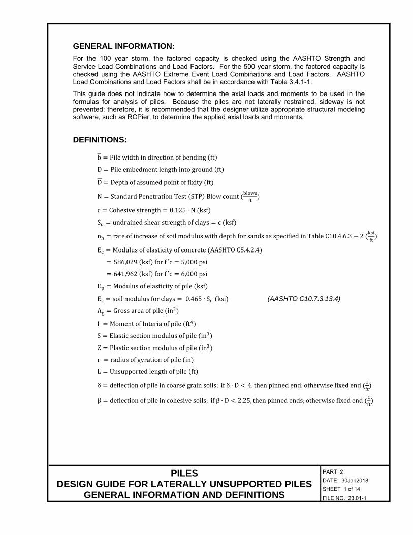
5. Select the point of fixity from the plotted curves. Point of fixity is where the deflection curve crosses the zero line when subjected to service lateral loads. There is no universal opinion as to whether fixity should occur at one or two crossings of the zero line. Choosing fixity at the second crossing would be a conservative assumption and will be used for this example.
The software used in this sample analysis is L-Pile 2016, Version 9. L-Pile is a multi-purpose program that can analyze a pile subjected to lateral loading. It computes deflection, shear, bending moment and soil response with respect to depth in nonlinear soils. The soil and rock is modeled using lateral load transfer curves (p-y) based on either published recommendations, or alternatively, user input p-y curves developed for each soil layer. Several types of pile head loading conditions may be selected along with the structural properties of the pile. The determination of point of fixity for a laterally loaded pile requires a pile deflection verse pile depth curve for all of the chosen load cases, as well as the soil profile along the length of pile. For this analysis, loads at the service limit state were chosen. Soils information from the boring logs was used in conjunction with the corresponding values for the soil properties provided in Tables 1 through 3 on File No. 23.01-3. The Coefficient of Horizontal Subgrade Reaction (k) was chosen by L-Pile using the user provided information.

PILES LATERAL LOADED PILE ANALYSIS FOR POINT OF FIXITY
DESIGN ASSUMPTIONS AND RESULTS
PART 2 DATE: 30Jan2018 SHEET 2 of 4
FILE NO. 23.02-2
DESIGN ASSUMPTIONS AND RESULTS: Loading: 1. The loads used for this example are per pile and unfactored. The loads used are 134 kips
vertical, 4.15 kips lateral longitudinal, 6.68 kips lateral transverse.
2. Moment at the top of pile was not used for this analysis. Both a fixed and free head (i.e., top of pile) condition is achievable without moment input, and therefore was not calculated for this example.
3. Since this analyses is for point of fixity, service limit state loads were used. Pile head deflection may have a limiting value depending on performance criteria that has been established. For this example, ½ inch at the top of pile is used.
4. Pile group effects were not considered.
5. In the longitudinal direction, the pile is assumed to be in a free head condition (i.e., rotation free and translation free). In the transverse direction, the pile is assumed to be in a fixed head condition (i.e., rotation fixed and translation free; slope equals zero).
Soils: 1. Soil properties used were determined using boring logs in conjunction with Tables 1 through
3 on File No. 23.01-3.
2. A 3.5 foot scour depth was assumed for this example. Results: 1. Plots of pile head deflection verse pile depth for scour and non-scour conditions are shown
on File Nos. 23.02-3 and -4, respectively.
2. The analysis considers the nonlinear properties of the soils. For this example, the effects of scour can be seen as negligible as shown by the top of pile deflections of the plots.
3. From both plots, the first inflection point is at a depth of approximately -18 ft. for the free head condition and approximately -23 ft. for the fixed head condition. The second inflection point occurs at approximately -36 ft. for both cases. The second inflection point is chosen for fixity and an unbraced length of 36 ft. below the pile head is assumed for determining the structural capacity of the pile.

PILES LATERAL LOADED PILE ANALYSIS FOR POINT OF FIXITY
L-PILE RESULTS FOR SCOUR CONDITION
PART 2 DATE: 30Jan2018 SHEET 3 of 4
FILE NO. 23.02-3
PILES LATERAL LOADED PILE ANALYSIS FOR POINT OF FIXITY
L-PILE RESULTS FOR NON-SCOUR CONDITION
PART 2 DATE: 30Jan2018 SHEET 4 of 4
FILE NO. 23.02-4

![[04899] - Design of Pile & Pile-Cap](https://static.fdocuments.net/doc/165x107/5695d3331a28ab9b029d273d/04899-design-of-pile-pile-cap.jpg)