Pigtail Nipper Operating Manual RevC
20
Operating & Maintenance Instructions For The Johnson Matthey 40 TON Bifurcated Pigtail Nipper Operating & Maintenance Instructions For The Johnson Matthey 40 TON Bifurcated Pigtail Nipper All enquires regarding this equipment should be directed to Services Manager Johnson Matthey Services PO Box 1 Billingham TS23 1LB England Telephone +44 1642 522206 Fax +44 1642 522542 22/05/06 Page 1 of 20 40 TON BIFURCATED PIGTAIL NIPPER
Transcript of Pigtail Nipper Operating Manual RevC

Operating & Maintenance Instructions For The Johnson Matthey 40 TON Bifurcated Pigtail Nipper
Operating & Maintenance Instructions
For The Johnson Matthey
40 TON Bifurcated Pigtail Nipper
All enquires regarding this equipment should be directed to Services Manager
Johnson Matthey Services PO Box 1 Billingham TS23 1LB England
Telephone +44 1642 522206
Fax +44 1642 522542
22/05/06 Page 1 of 20
40 TON BIFURCATED PIGTAIL NIPPER

Operating & Maintenance Instructions For The Johnson Matthey 40 TON Bifurcated Pigtail Nipper
1 Contents
1 Contents ...........................................................................................................2
2 Introduction......................................................................................................3
3 Problems Associated with Nipping Inlet Pigtails..........................................3
4 Problems Associated with Nipping Exit Pigtails...........................................4
4.1 Carburisation ...............................................................................................4
4.2 Creep ..........................................................................................................5
4.3 Clamp Plate Relaxation ...............................................................................5
4.4 Tube Selection ............................................................................................5 5 Description of the Equipment.........................................................................6
6 Assembly..........................................................................................................7
6.1 Important Note.............................................................................................8 7 Operation..........................................................................................................9
7.1 Detailed Procedure for Nipping Exit Pigtails ................................................9
7.2 Detailed Procedure for Nipping Inlet..........................................................11 8 Precautions ....................................................................................................12
9 Maintenance of Equipment ...........................................................................12
10 Footnotes .......................................................................................................12
11 Appendix 1 Contents of Box.......................................................................13
12 Appendix 2 Details of Pump ........................................................................15
13 Appendix 3 Material Safety Data Sheet.......................................................16
14 Appendix 4 Modification to lower clamp plate for thin pipe walls ..........20
22/05/06 Page 2 of 20
Operating & Maintenance Instructions For The Johnson Matthey 40 TON Bifurcated Pigtail Nipper
2 Introduction
The principle of performing an on line isolation of a leaking reformer tube by squeezing flat the inlet and exit pigtails was developed by ICI on the naphtha reformers at Heysham in the 1960's and subsequently used on other ICI reformers at Billingham, Severnside and Immingham. Perhaps as many as 1000 reformer tubes have been isolated successfully on ICI operated reformers. The technique which became known as pigtail nipping has been used by many other reformer operators throughout the world using equipment supplied by ICI. Johnson Matthey now provides this service. As the process of nipping pigtails became known more widely, ICI received an increasing number of enquiries from reformer operators who could not use the original design of pigtail nipper either because the pigtails were too closely spaced or in a few cases because the exit pigtails were too strong. ICI therefore decided to design a new and more powerful nipper to overcome these limitations and to be capable of giving a successful nip with just one application of the equipment instead of the two required when using the original design. The design also took account of the possibility that the clamp plates may have to operate in a hot environment. The result was a Pigtail Nipper with a load rating of 40 tons. This superseded the earlier equipment's rating of 20 tons. This nipper can be used on many different types of furnace to nip pigtails of a wide range of sizes and wall thicknesses. Johnson Matthey is prepared to give advice to users on the particular circumstances of their plant and if necessary for an agreed fee carry out tests on samples of the pigtails.
3 Problems Associated with Nipping Inlet Pigtails
Inlet pigtails are usually fabricated from carbon steel, carbon half moly, chrome/moly, stainless steel or in some rare instances Incoloy 800. Of these, Incoloy 800 is the ideal material from a nipping point of view. It does not deteriorate and is more than sufficiently ductile to prevent cracking. Stainless steel may suffer from stress corrosion cracking, but otherwise it too can readily be nipped. Some chrome/moly pigtails can be nipped at normal operating temperature without any problems, but others crack. It appears that the higher the ratio of wall thickness/OD the more likely it is that nipping will be performed without cracking. Carbon steel and carbon half moly pigtails will usually (but not always) crack if nipped at normal operating temperatures and for this reason they are not recommended as inlet pigtail materials. For plants that already have inlet pigtails made from carbon half moly or carbon steel it is recommended that a section be removed at a point convenient for nipping and replaced with a 25 - 30 cm length of Incoloy 800. The incoloy insert should have the same ID as the original material. This procedure has been adopted on several ICI
22/05/06 Page 3 of 20

Operating & Maintenance Instructions For The Johnson Matthey 40 TON Bifurcated Pigtail Nipper
operated reformers, but the more recent ICI furnaces were fitted with complete pigtails in Incoloy 800.
4 Problems Associated with Nipping Exit Pigtails
4.1 Carburisation Exit pigtails are usually fabricated from Incoloy 800, which at normal exit reformer tube temperatures can deteriorate in service due to the reaction between the chromium in the alloy and the carbon containing gases in the process stream. This reaction, known as carburisation, increases with increasing temperature and results in the formation of a brittle layer extending from the bore of the pigtail into the pigtail wall. ICI experience suggests that when carburisation has penetrated to more than 40% of the wall thickness then the pigtail may crack if it is nipped. However, because the carburised layer is magnetic whereas the new material is not, the thickness of the carburised layer can be estimated using an Elcometer thickness gauge. During the annual shutdown of the reformer Johnson Matthey recommend that all the exit pigtails be checked with the No 32 scale Elcometer thickness gauge (model type 101), which must first be standardised as described in the instrument's instruction card. Several readings are then taken at different points along the pigtail and at different places around the circumference of the pigtail. It is particularly important that readings be taken in the area where the pigtail would be nipped and that the pigtails are at ambient temperatures when the readings are taken. The instrument calibration should be checked frequently (after testing every 2 or 3 pigtails). If the average of the Elcometer readings for a given pigtail is above the rejection point, then file the surface of the pigtail to bright metal at several points and repeat the Elcometer Measurements. It is just possible that the high Elcometer readings were due to a thin layer of scale (magnetite on the outside and not to carburisation of the bore. If the readings are still above the rejection point then the pigtail should be replaced. The rejection point will vary for different pigtail wall thicknesses. For pigtails with wall thicknesses up to 5 mm (0.2 inches) the rejection point is 17% ferrite, for a wall thickness of 5 - 6.3 mm (0.2 - 0.25 inches) the rejection point is 14% ferrite and for pigtails with wall thicknesses above 6.3 mm (0.25 inches) the rejection point is 10% ferrite. These recommendations are based on Johnson Matthey’s experience of nipping pigtails with wall thicknesses in the range 3.75 - 5 mm (0.148 - 0.2 inches) and with pigtails with a wall thickness of 7.1 mm (0.28 inches). In both cases the rejection point corresponds to approximately 20 - 25% carburisation of the wall. We have found both from laboratory tests and from plant experience that this level of carburisation gives rise to no problems when the pigtails are nipped. The figures are almost certainly conservative but since the use of the Elcometer is not in itself precise, this is considered to be the safest policy. Because Johnson Matthey has no plant experience of pigtails with wall thicknesses in the range 5 - 7.1 mm (0.2 - 0.28 inches) and wall thicknesses greater than 7.1 mm (0.28 inches), it is recommended that any pigtails of these sizes that are
22/05/06 Page 4 of 20
Operating & Maintenance Instructions For The Johnson Matthey 40 TON Bifurcated Pigtail Nipper
replaced should be examined under a microscope to determine the percentage carburisation. Samples should also be tested to confirm that the pigtails are not going to fail when nipped. These tests could indicate that pigtail with higher levels of carburisation can be safely nipped but the test result should be interpreted conservatively.
4.2 Creep Like excessive carburisation, creep can be a source of trouble when nipping incoloy pigtails. The area where the pigtail is to be nipped must be checked for creep. Johnson Matthey use what is referred to as "Go - No Go" gauge to check that creep is not more than 2½%. The gauge is U-shaped with the clearance between the parallel vertical arms of the 'U' being equal to 1,025 times the diameter of the pipe at normal working temperature. Such a gauge can be used to scan the pigtail near the point where it is to be nipped. The pigtails are also checked for creep at shutdown and any pigtails which show creep of more than 2.5% of the cold diameter are replaced.
4.3 Clamp Plate Relaxation If the design of the reformer is such that the exit pigtails are not individually lagged and are therefore located in an insulated box, then the clamp plates and bolts which remain fastened to a pigtail after nipping will heat up and thus tend to relax. The design of the clamp plates and bolts makes some allowance for this but the problem can be minimised by arranging for a stainless steel pipe with an ID of approximately 50 mm (2 inches) to be passed through the wall of the insulated box to allow cold air to be drawn over the clamp plates.
4.4 Tube Selection Although it may be quite obvious from looking through the furnace inspection doors which tube has failed, this is not always the case and it can often be very difficult to decide which is the leaking tube. The tube failure will frequently give rise to a sharp jet-like flame which can vary in colour from yellow near the top of the tube to blue towards the bottom of the tube. The flame can impinge on adjacent tubes causing hot spots or on the furnace wall causing incandescence. It is always worthwhile numbering the tubes using chalk or a suitable paint such as Dulux Supermatt which contains no zinc or lead. The numbers should be painted in such a place so that they can be seen from the observation doors. If this is not possible then painting numbers or lines at gradually decreasing levels on the tubes (as one looks from one end of the furnace to the other) can help overcome the on-line identification problem. Better still perhaps, is to mark the tubes in groups of 10 with tube 1 marked at (say) 1 metre from the furnace roof, tube 10 marked at (say) 3 or 4 metres from the roof, then tube 11 marked at 1 metre and so on.
22/05/06 Page 5 of 20

Operating & Maintenance Instructions For The Johnson Matthey 40 TON Bifurcated Pigtail Nipper
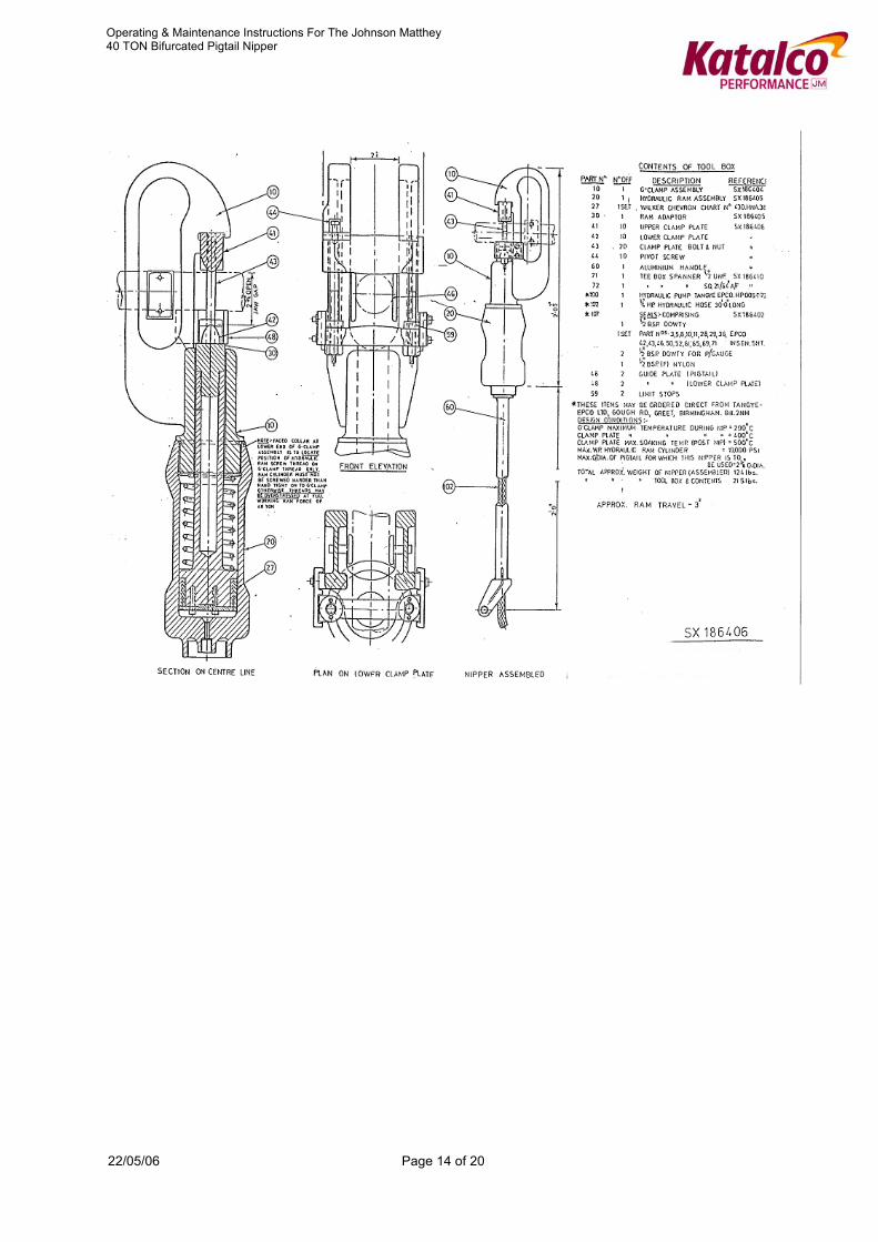
5 Description of the Equipment
The contents of the pigtail nipper toolbox are listed in Appendix 1. This drawing also shows a general arrangement and details of the G clamp and hydraulic ram assembly. The hydraulic pump made by Tangye Epco Limited is fitted with a 0 - 690 bar g (0 - 10,000 psig) pressure gauge and attached to a 3.8 litre (1 gallon) size hydraulic oil reservoir. The reservoir is bolted to the base of the tool chest in order to provide an anchorage for the pump. Appendix 2 shows details of the pump together with a parts list. Spares for the g-clamp and hydraulic ram assembly can be obtained from Johnson Matthey, but spares for the hydraulic pump should be obtained directly from Tangye Epco Limited. The bifurcated (split) g-clamp (10) and the hydraulic ram assembly (2) are supplied screwed together as one unit. The base of the hydraulic cylinder is fitted with two screw connections, one for the hydraulic hose (102) linking the pump to the ram assembly and one for the aluminium alloy handle (60). The g-clamp is fitted with guide plates (46) which are adjusted for individual pigtails using packing, to allow the nipper to be located centrally on the pigtail and with guides (48) for the lower clamp plate (42). These guides prevent the lower clamp plate from twisting during the early part of the nipping process. The upper clamp plate (41) which is restrained by slots cut into each web of the g-clamp, is fitted with a pivot screw (44). This screw (44) allows the upper clamp plates to drop just clear of these slots, so that with the right hand (viewing the front elevation) clamp plate bolt (43) removed the upper clamp plate can be swung round through 90° such that it lies in the plane of the left hand web of the g-clamp (open position). The g-clamp can thus be positioned on the pigtail with the pigtail up against the lower clamp plate. The upper clamp plate is then swung back through 90° and re-located in the slots (closed position), the right hand clamp plate bolt and nut are screwed in, and pressure applied by the pump to commence the nipping of the pipe. To prevent any possibility of the nipper cutting the pigtail in half, the lower clamp is fitted with limit stops (59) which must be machined to suit the wall thickness of the pigtail and which limit the gap between the upper and lower clamp plates. The Hydrapak hydraulic pump is a 2-speed light-weight totally enclosed pump made from non corrodible alloys and suitable for use with oil or water. It is fitted with a standard low-pressure plunger which has an output of 50.8 cc (3.1 cu in) per stroke and a maximum pressure of 52 bar (750 lbs per sq in). The high pressure plunger has a displacement of 3.6 cc (0.221 cu ins) which gives a maximum working pressure of 690 bar g (10,000 psig). All valves etc are readily accessible for cleaning and maintenance and a suction filter is fitted for protection against the ingress of dirt, etc. In addition to the operating handle, there are two controls; a release valve (Item 55) and a push/pull pressure-selection button (Item 32). The pump is fitted with a rubber faced delivery valve and ball-type suction valves, one for high pressure and one for low pressure. When the pump is operating on low pressure, both high and low pressure pistons are operative. The action of the pressure selection button is to lift the low-pressure suction ball off its seat so that the low-pressure system is rendered inoperative; only the high-pressure piston is then effective.
22/05/06 Page 6 of 20
Operating & Maintenance Instructions For The Johnson Matthey 40 TON Bifurcated Pigtail Nipper
Oil is preferable as the hydraulic medium because of its lubricating qualities. Good quality hydraulic oil should be used, having a viscosity of Redwood 310 seconds at 21°C (70°F). (5 litres [one gallon] of Shell WG Fluid, Type C Fire Resistant hydraulic fluid is supplied with the equipment. If for some reason it is decided to replace the oil with water, the water used should be clean and soft, and should be changed regularly to prevent build-up of impurities. Another suitable hydraulic fluid is Mobil PYROGARD D, a non-flammable emulsion. See Appendix 3 for the Material Safety Data Sheet (MSDS) for the oil provided.
6 Assembly
1. Remove the (g-clamp/nipper hydraulic ram assembly) from the toolbox. 2. Screw the hydraulic hose into the discharge port of the pump.
3. Thread the hose pipe through the aluminium alloy handle for the nipper (if
required).
4. Attach pump lever to pump ensuring there is enough space for handle to travel through its full range of motion.
5. Close the pump release valve. Pull out the pressure selector button. Operate
the pump to expel the air ensuring that the open end of the hose is held over the oil reservoir in order to return the excess oil.
6. Screw the hose and nipper handle to the end of the hydraulic cylinder.
7. Make any necessary adjustment to the pigtail guide plate packing washers to
ensure that the nipper can be located centrally on the hot pigtail.
8. Select a pair of clamp plates which must be fitted with the appropriate limit stops, a pair of clamp plate nuts and bolts, and a clamp plate pivot screw.
9. Check that the nuts run smoothly on the clamp plate bolts, that the bolts run
smoothly into the upper clamp plates and that when fully screwed in, the bolts do not protrude above the back face of the upper clamp plate.
10. Leave one bolt screwed into the upper clamp plate and screw the pivot screw
into the end of this bolt.
11. Fit the clamp plates into the g-clamp, sliding the lower clamp plate into the guide, and checking that clamp plate pivot screw is so adjusted that it does not foul on the top of its recess in the g-clamp when the upper clamp plate is held firmly in its slots. Check also that the upper clamp plate can swing freely on the pivot screw.
22/05/06 Page 7 of 20

Operating & Maintenance Instructions For The Johnson Matthey 40 TON Bifurcated Pigtail Nipper
12. With the lower clamp plate resting on the top of the ram adapter run up the nut on the one clamp plate bolt.
13. Fit any lifting lugs for the nipper that are required for the nipper support
system.
14. Load the nipper and the tool chest containing the pump onto a trolley and prepare to go to the reformer site. The two men operating the nipper and the man operating the pump should put on their protective clothing.
6.1 Important Note As supplied the upper and lower clamp plates are profiled for pigtails with a wall thickness greater than schedule 80. Where the pigtail wall thickness is less than, or equal to schedule 80, the upper and lower clamp plate profile should be modified to that shown on drawing number SX186408. (Appendix 4). On some plants it may be necessary to have clamp plates of both profiles because of the different wall thicknesses of the inlet and exit pigtails. The lower clamp plates are fitted with limit stops (Part 59) which may need to be machined down or fitted with packing so that the height of the stop is as follows: Pigtails up to and including schedule 80 wall thickness
Wall Thickness Limit Stop Height Less than 5.1mm (0.2 inch)
1.7 w + 1.59 mm (1.7 W + 0.0625 inch)
5.1 to 6.4 mm (0.2 to 0.25 inch)
1.6 w + 1.59 mm (1.6 W + 0.0625 inch)
Greater than 6.4 mm (0.25 inch)
1.5 w + 1.59 mm (1.5 W + 0.625 inch)
Where w and W are the minimum wall thicknesses of the pigtails in mm and inches respectively. Pigtails above schedule 80 wall thickness
Wall Thickness Limit Stop Height Less than 5.1mm (0.2 inch)
1.7 w + 3.18 mm (1.7 W + 0.125 inch)
5.1 to 6.4 mm (0.2 to 0.25 inch)
1.6 w + 3.18 mm (1.6 W + 0.125 inch)
Greater than 6.4 mm (0.25 inch)
1.5 w + 3.18 mm (1.5 W + 0.125 inch)
Where w and W are the minimum wall thicknesses of the pigtails in mm and inches respectively. If the nipper is used on the inlet and exit pigtails then assuming the pigtails have different wall thicknesses two sets of limit stops and possibly modified and standard clamp plates will be required. It is recommended that sets of clamp plates, spacers, clamp bolts and nuts are assembled and marked for the inlet or exit pigtails. Similarly
22/05/06 Page 8 of 20
Operating & Maintenance Instructions For The Johnson Matthey 40 TON Bifurcated Pigtail Nipper
the pigtail guide plates (Part 46) will need to be re-adjusted by removing or fitting extra packing washers unless the inlet and exit pigtails are of the same OD.
7 Operation
Depending upon what type of support system is used for the reformer tubes, some precautions may be required to protect the support system in the event of the reformer tube failing completely at a weld. This sometime happens when the reformer tube heats up to flue gas temperature after being isolated. On one of its furnaces with bottom supported tubes, Johnson Matthey has provided a retaining clamp which is fitted to the reformer tube top flange to limit excessive expansion of the tube and so prevent the tube tensioning system from being unbalanced (4 tubes are tensioned together). On its top supported furnaces, a platform is constructed a few inches below the tube bottom flange to catch any reformer tube that fails after nipping and so prevent it from falling completely out of the furnace. In deciding whether to nip the inlet or the exit pigtail first, consideration must be given to which pigtail will be the more difficult to nip at lower temperatures. With chrome/moly inlet pigtails operating at 450°C or above it is recommended that these be nipped first so that the material remains in its most ductile condition. When the inlet pigtails are of stainless steel or have Incoloy 800 inserts then the exit pigtail should be nipped first as this will normally require the greatest load and will therefore benefit most from being at its maximum temperature. When the nipper is being used on furnaces where the exit pigtails are not individually lagged and are contained in an insulated box, the box will have to be opened to give access to the pigtails. If a large section of the box is removed then it will be advisable to prepare some temporary insulation plates to protect the nipper operators from excessive radiation.
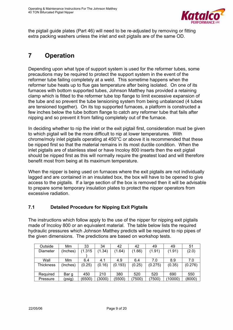
7.1 Detailed Procedure for Nipping Exit Pigtails The instructions which follow apply to the use of the nipper for nipping exit pigtails made of Incoloy 800 or an equivalent material. The table below lists the required hydraulic pressures which Johnson Matthey predicts will be required to nip pipes of the given dimensions. The predictions are based on workshop tests.
Outside Mm 33 34 42 42 49 49 51 Diameter (Inches) (1.315
) (1.34) (1.64) (1.66) (1.91) (1.91) (2.0)
Wall Mm 6.4 4.1 4.9 6.4 7.0 8.9 7.0
Thickness (Inches) (0.25) (0.16) (0.193) (0.25) (0.275) (0.35) (0.276)
Required Bar g 450 210 380 520 520 690 550 Pressure (psig) (6500) (3000) (5500) (7500) (7500) (10000) (8000)
22/05/06 Page 9 of 20

Operating & Maintenance Instructions For The Johnson Matthey 40 TON Bifurcated Pigtail Nipper
A. Determine which tube is to be isolated and ensure that the correct inlet and exit pigtails are selected for nipping. Prepare the necessary support system for the nipper.
B. Fit any support or clasp system that is required to protect the furnace in the
event of the reformer tube failing completely.
C. Attach the nipper to the support system and position the pump at the extremity of the hose.
D. Raise the nipper up near the pigtail. 'Open' the upper clamp plate and locate
the nipper on the pigtail. Hold it so that the lower clamp plate is hard up against the pigtail. 'Close' the upper clamp plate and allow the nipper to rest on the upper clamp plate. Check that the upper clamp plate is resting squarely in its slots in the g-clamp.
E. Fit the second clamp plate bolt and nut and check that there is room to do a
second nip on either side of the first nip, should this be necessary.
F. Apply an oil pressure of 50 bar g (750 psig) using the low pressure range of the pump and check that the nipper is square to the line of the pigtail.
G. The two men handling the nipper should then retire whilst the oil pressure is
increased to the recommended pressure using the HP setting on the pump pressure selector.
H. Wait 30 seconds. Listen for sounds of escaping gas before approaching.
Carefully inspect the pigtail for leakage or any signs of cracking in the area of the nip.
I. Tighten up the nuts on the clamp plate bolts using the long-handled spanner,
finishing off with a ring spanner, release the pressure and after pausing for 10 - 20 seconds to allow the ram to retract, unhook the nipper from the pigtail.
J. After confirming that the nipping of the inlet pigtail is complete, examine the
reformer tube to check that the leak has been sealed (or reduced to an acceptable level). If not, then either the inlet or exit pigtail (or both) will have to be nipped again on the tube side of the first nip.
K. To help to decide which pigtail to nip first, checking the temperatures may
indicate which one still has some hot gas passing through it. If the tube failure is near the top of the tube then if the leak is through the inlet pigtail the flame will tend to be yellowish whereas it will be a clear/blue flame if the leak is reformed gas from the exit pigtail. It may be possible to 'hear' which pigtail is leaking using an ultrasonic detector.
L. Where required fit a stainless steel pipe to direct cold air onto the clamp plate.
This should be done once flame emission has been eliminated or reduced to an acceptable level.
22/05/06 Page 10 of 20

Operating & Maintenance Instructions For The Johnson Matthey 40 TON Bifurcated Pigtail Nipper
In the days/weeks after a tube has been isolated it is usual for any remaining leak to gradually disappear due to the pigtails choking up with carbon, pipe scale or catalyst dust. A careful watch should be maintained on the isolated tube to ensure that any leak does not deteriorate, if it does then this could be due to some relaxation of the clamp plate bolts on the exit pigtails.
7.2 Detailed Procedure for Nipping Inlet If the pigtails are made of Incoloy 800 or have incoloy inserts then the hydraulic pressure listed in the table (in Section 6.2) above should be used but if the pigtails are made of chrome/moly then the table below should be used when selecting the required hydraulic pressure. Workshop tests should also be performed to confirm these pressures.
Outside Mm 21 33 41 42 44 Diameter (Inches) (0.844) (1.315) (1.63) (1.66) (1.75) Wall Mm 4.1 3.4 3.3 3.6 4.6 Thickness (Inches) (0.16) (0.133) (0.13) (0.14) (0.18) Required Bar g 280 240 210 350 350 Pressure (psig) (4000) (3500) (3000) (5000) (5000)
A. Check that limit stops suitable for use with the inlet pigtails have been fitted to
the lower clamp plate. B. Prepare the support system for the nipper.
C. Attach the nipper to the support system and position the pump at the extremity
of the hose.
D. Raise the nipper up near the pigtail, 'open' the upper clamp plate and locate the nipper on the pigtail, holding it so that the lower clamp plate is hard up against the pigtail. 'Close' the upper clamp plate and allow the nipper to rest on the upper clamp plate, checking that the upper clamp plate is resting squarely in its slots in the g-clamp.
E. Fit the second clamp plate bolt and nut and check that there is room to do a
second nip on either side of the first nip, should this be necessary.
F. Apply an oil pressure of 50 bar g (750 psig) using the low pressure range of the pump and check that the nipper is square to the line of the pigtail.
G. The two men handling the nipper should then retire whilst the oil pressure is
increased to the recommended pressure using the HP setting on the pump pressure selector.
H. Wait 30 seconds, listening for sounds of escaping gas before approaching,
then carefully inspect the pigtail for leakage or any signs of cracking in the area of the nip.
22/05/06 Page 11 of 20
Operating & Maintenance Instructions For The Johnson Matthey 40 TON Bifurcated Pigtail Nipper
I. Tighten up the nuts on the clamp plate bolts wing the long-handled spanner, finishing off with a ring spanner, release the pressure and after pausing for 10 - 20 seconds to allow the ram to retract, unhook the nipper from the pigtail.
8 Precautions
On furnaces where the exit pigtails are not individually lagged, the operators handling the nipper should wear full, air-cooled protective suits to obtain good protection from radiated heat. It is also advisable that the pump operator wear such a suit in case he is called upon to assist his colleagues. When the exit pigtails are individually lagged then only fire resistant headsets with suitable gloves will probably be adequate protective clothing.
9 Maintenance of Equipment
Occasionally the pump rocker shaft bearing surfaces should be charged with a medium grease via the nipple provided and the suction strainer should be washed out thoroughly in clean paraffin to remove all the filtered dirt. The release valve must be closed before the strainer is removed otherwise the system will drain itself through the passageway. Vent the air from the pump after replacing the filter. After three nipping operations unscrew the hydraulic ram from the g-clamp. Inspect the piston on all its bearing surfaces for dirt or grit, clean off and smear the surfaces with hydraulic fluid. Inspect the sealing rings for wear and if apparent renew them. Finally check for smooth free movement of the piston assembly and an easy positive return of the piston under the action of the return spring. Check that the lower clamp plates will move smoothly in the guides and if necessary remove any burrs with a honing stone.
10 Footnotes
1. Frequent reference is made in these instructions to Incoloy 800 which is a trade name used by Henry Wiggins and Company. In this context Incoloy 800 should be interpreted to mean any alloy 800 which meets the standard ASTMS B407 and not just Incoloy 800.
2. If, despite air-cooling, clamp plate relaxation is found to be a problem, ie if the
nip tends to deteriorate resulting in a gradually increasing flame at the tube failure, then over clamp plates should help to overcome this. The details of the over clamp plates will vary from furnace to furnace.
3. Whenever time allows, advantage should be taken of any brief reformer
shutdowns to cut the pigtails of isolated tubes and to weld in plugs.
22/05/06 Page 12 of 20
Operating & Maintenance Instructions For The Johnson Matthey 40 TON Bifurcated Pigtail Nipper
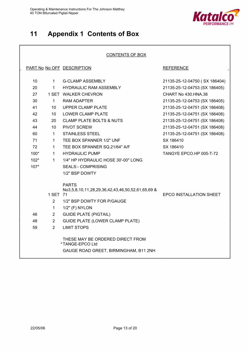
11 Appendix 1 Contents of Box
CONTENTS OF BOX PART No No OFF DESCRIPTION REFERENCE 10 1 G-CLAMP ASSEMBLY 21135-25-12-04750 ( SX 186404) 20 1 HYDRAULIC RAM ASSEMBLY 21135-25-12-04753 (SX 186405) 27 1 SET WALKER CHEVRON CHART No 430.HNA.38 30 1 RAM ADAPTER 21135-25-12-04753 (SX 186405) 41 10 UPPER CLAMP PLATE 21135-25-12-04751 (SX 186408) 42 10 LOWER CLAMP PLATE 21135-25-12-04751 (SX 186408) 43 20 CLAMP PLATE BOLTS & NUTS 21135-25-12-04751 (SX 186408) 44 10 PIVOT SCREW 21135-25-12-04751 (SX 186408) 60 1 STAINLESS STEEL 21135-25-12-04751 (SX 186408) 71 1 TEE BOX SPANNER 1/2" UNF SX 186410 72 1 TEE BOX SPANNER SQ.21/64" A/F SX 186410 100* 1 HYDRAULIC PUMP TANGYE EPCO.HP 005-T-72 102* 1 1/4" HP HYDRAULIC HOSE 30'-00" LONG 107* SEALS:- COMPRISING 1/2" BSP DOWTY
1 SET
PARTS No3,5,8,10,11,28,29,36,42,43,46,50,52,61,65,69 & 71 EPCO INSTALLATION SHEET
2 1/2" BSP DOWTY FOR P/GAUGE 1 1/2" (F) NYLON 46 2 GUIDE PLATE (PIGTAIL) 48 2 GUIDE PLATE (LOWER CLAMP PLATE) 59 2 LIMIT STOPS
* THESE MAY BE ORDERED DIRECT FROM TANGE-EPCO Ltd
GAUGE ROAD GREET, BIRMINGHAM, B11 2NH
22/05/06 Page 13 of 20
Operating & Maintenance Instructions For The Johnson Matthey 40 TON Bifurcated Pigtail Nipper
22/05/06 Page 14 of 20
Operating & Maintenance Instructions For The Johnson Matthey 40 TON Bifurcated Pigtail Nipper
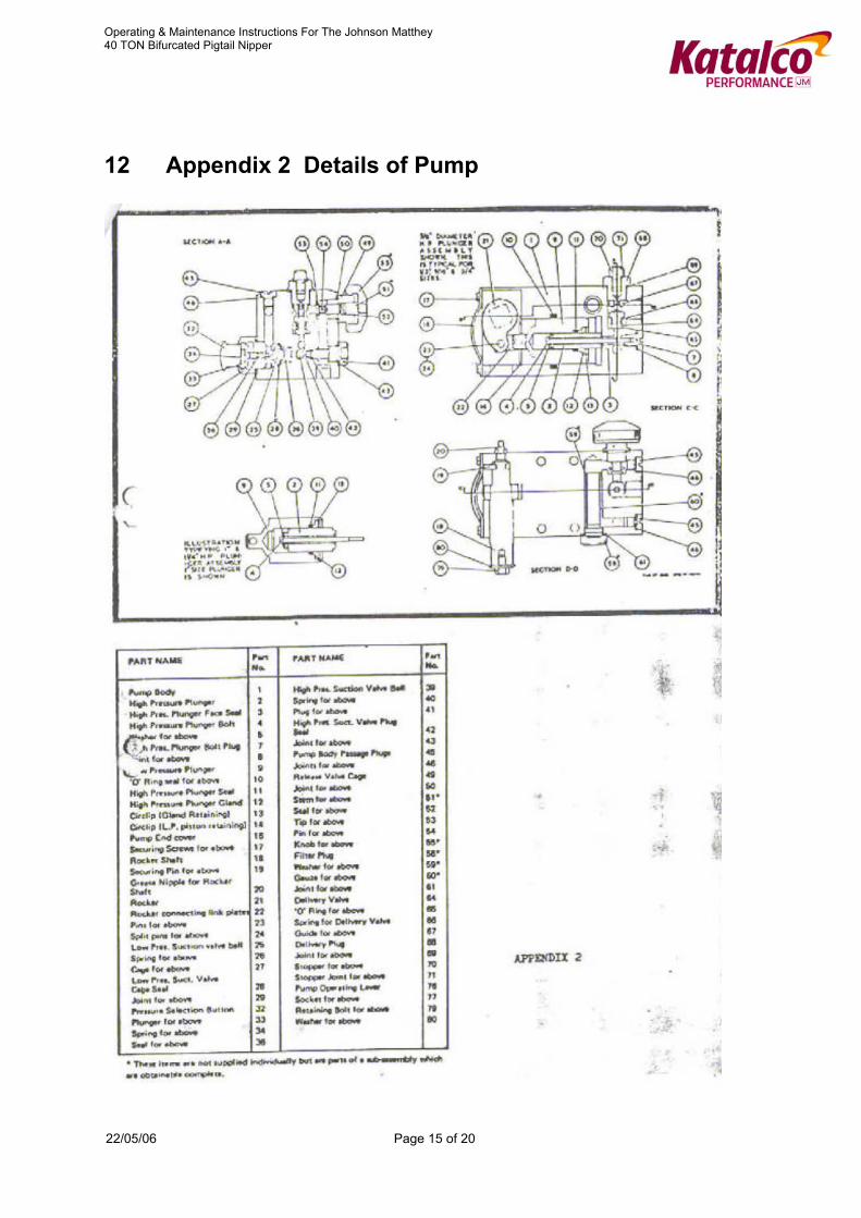
12 Appendix 2 Details of Pump
22/05/06 Page 15 of 20

Operating & Maintenance Instructions For The Johnson Matthey 40 TON Bifurcated Pigtail Nipper
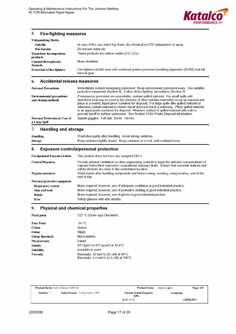
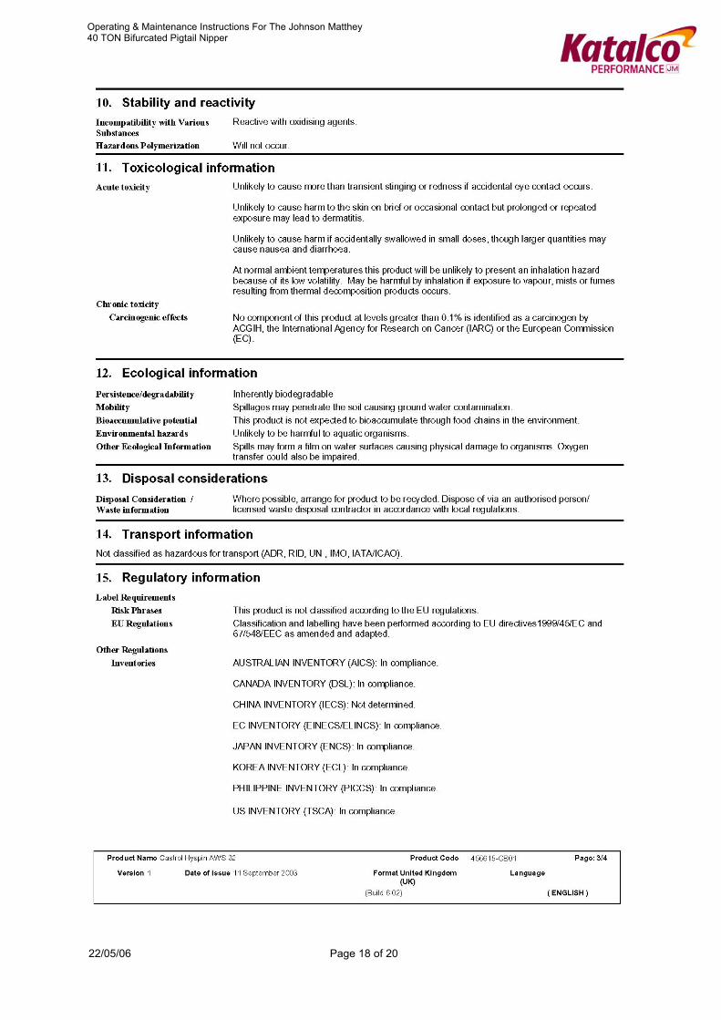
13 Appendix 3 Material Safety Data Sheet
22/05/06 Page 16 of 20
Operating & Maintenance Instructions For The Johnson Matthey 40 TON Bifurcated Pigtail Nipper
22/05/06 Page 17 of 20
Operating & Maintenance Instructions For The Johnson Matthey 40 TON Bifurcated Pigtail Nipper
22/05/06 Page 18 of 20

Operating & Maintenance Instructions For The Johnson Matthey 40 TON Bifurcated Pigtail Nipper
22/05/06 Page 19 of 20

Operating & Maintenance Instructions For The Johnson Matthey 40 TON Bifurcated Pigtail Nipper
22/05/06 Page 20 of 20
14 Appendix 4 Modification to lower clamp plate for thin pipe walls