PHV V NT VERTICAL AIR CURTAINS INSTALLATION, OPERATION & MAINTENANCE...
25
9901020-6 Page 1 of 25 PHV V NT VERTICAL AIR CURTAINS INSTALLATION, OPERATION & MAINTENANCE INSTRUCTIONS PLEASE READ THESE INSTRUCTIONS CAREFULLY BEFORE ATTEMPTING INSTALLATION Thermoscreens Ltd St. Mary’s Road Nuneaton Warwickshire England CV11 5AU Email: [email protected] Tel: +44 (0) 24 7638 4646 Fax: +44 (0) 24 7638 8578 www.thermoscreens.com
Transcript of PHV V NT VERTICAL AIR CURTAINS INSTALLATION, OPERATION & MAINTENANCE...

9901020-6 Page 1 of 25
PHV V NT VERTICAL AIR CURTAINS
INSTALLATION, OPERATION & MAINTENANCE INSTRUCTIONS
PLEASE READ THESE INSTRUCTIONS CAREFULLY BEFORE ATTEMPTING INSTALLATION
Thermoscreens Ltd
St. Mary’s Road Nuneaton Warwickshire England
CV11 5AU
Email: [email protected] Tel: +44 (0) 24 7638 4646 Fax: +44 (0) 24 7638 8578 www.thermoscreens.com
9901020-6 Page 2 of 25
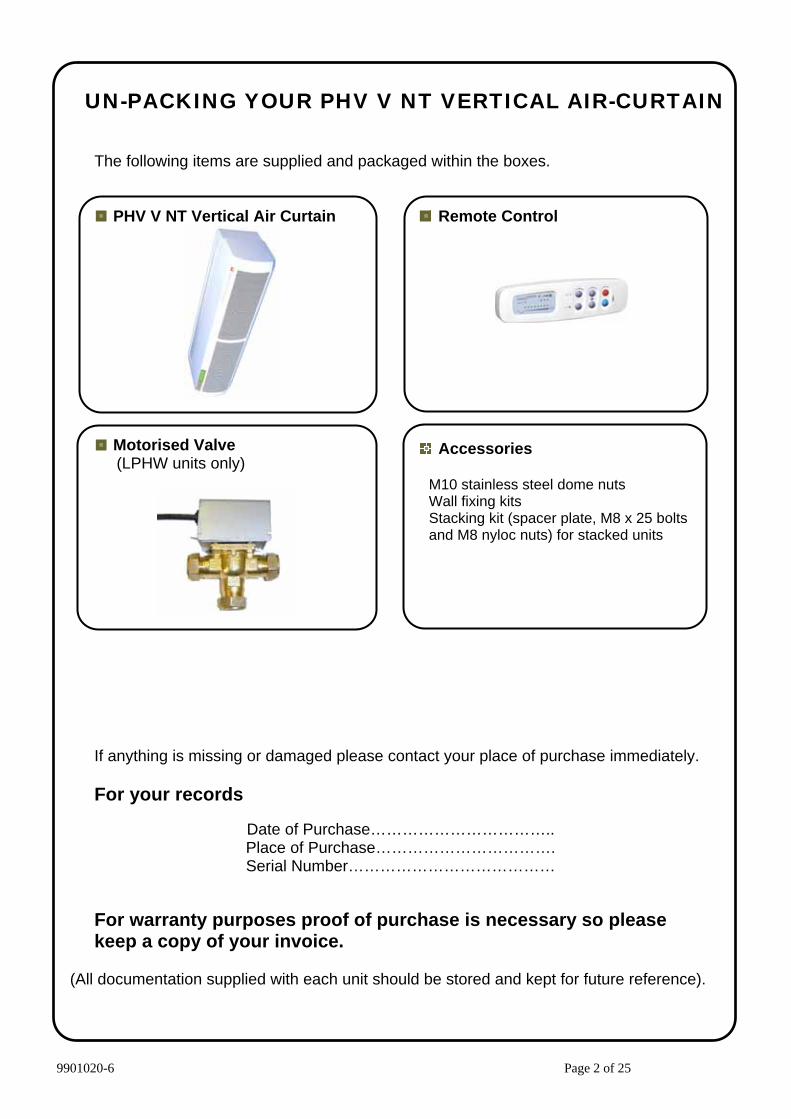
UN-PACKING YOUR PHV V NT VERTICAL AIR-CURTAIN
The following items are supplied and packaged within the boxes.
PHV V NT Vertical Air Curtain
Motorised Valve (LPHW units only)
Remote Control
Accessories
M10 stainless steel dome nuts Wall fixing kits Stacking kit (spacer plate, M8 x 25 bolts and M8 nyloc nuts) for stacked units
If anything is missing or damaged please contact your place of purchase immediately. For your records
Date of Purchase…………………………….. Place of Purchase……………………………. Serial Number…………………………………
For warranty purposes proof of purchase is necessary so please keep a copy of your invoice.
(All documentation supplied with each unit should be stored and kept for future reference).

9901020-6 Page 3 of 25
INSTALLATION OF YOUR VERTICAL APPLICATION PHV V NT AIR CURTAIN
The air curtain must be surface mounted within the building and not exposed to the external environment or moist conditions. Do not install the air curtain in a
doorway situation where there is a likelihood, or there has been a history of, rain ingress. The air curtain must not be built into a compartment or recessed.
Location
Prior to commencing any vertical installation it is essential to ensure the correct handing has been selected, i.e. Left Hand (LH) or Right Hand (RH) - . see “Handing Guide” in Figure 1. Maximum doorway width = 2m per air curtain.
The air curtain should be located close to the door opening with the air discharge grille positioned nearest to the door. For maximum effectiveness it is essential to ensure the top of the air curtain is slightly higher than the opening height of the door. Obstructions such as door opening devices, structural beams etc will reduce the efficiency of the air curtain.
Floor Fixing
Before installing the air curtain obtain four suitable M10 fixing bolts, taking into account floor type and unit weight (See Table 1)*. Rawlplug ® M10 Projecting Rawlbolt ® 44356 type may be suitable. For dimensional details refer to the general assembly drawing, Figure 1.
Determine and place the unit in position. A wall bracket is provided to secure the vertical air curtain to the wall and this must be used. So that the wall bracket touches the wall, ensure the back of the base plate touches against the wall, skirting board will need to be cut away if necessary.
Using the base plate as a template, mark the location of the four holes, as indicated in the adjacent picture.
Using a suitable masonry drill bit correctly drill the four marked out holes. Place M10 fixing bolts into each hole, ensuring all bolts are upright. Reposition the air curtain base plate over the projecting bolts. Tighten each M10 nut as indicated in the adjacent picture. Ensure the vertical unit is secure, level and square. It may be necessary to pack under the base plate to ensure unit is vertical. Using a hacksaw carefully cut the projecting bolt flush with the nut, ensuring the base plate is not damaged or marked in any way.
Base plate to touch wall (cut away skirting board)

9901020-6 Page 4 of 25
Remove only one M10 nut and refit and resecure bolt with a stainless steel M10 dome nut supplied. Repeat for each of the other three projecting bolts one at a time.
Stacking of Units
PHV1500V and PHV2000V air curtains are delivered as single units. PHV2500V and PHV3000V air curtains are delivered as separate 1.5m + 1m air curtains for a PHV2500V unit and 2m + 1m air curtains for a PHV3000V unit. The 1m air curtain must always be mounted as the top unit using the stacking kit supplied to secure it to the bottom unit. The spacer plate, in the stacking kit must be bolted between the two units using the 4 off M8 x 25 bolts and nyloc nuts. This will allow the removal of access panels when required. All wall brackets must be used to properly secure both the bottom and top air curtains in the stack to the wall (See Figure 1). * It is the sole responsibility of the installer to ensure that all the fixing points and bolts used are suitable for the air curtain.
Attention: The panels of the air curtain are coated in an easy to peel protective film. Please ensure all the protective film is removed before the air curtain is put into service.

9901020-6 Page 5 of 25
ENTERING AIR
DISCHARGE AIR
Vie
w 'A
'
Vie
w 'B
'
Vie
w 'A
'
As
draw
n fo
r R.H
.O
ppos
ite h
and
for L
.H.
Bol
t Hol
es fo
r M10
Raw
l bol
ts -
4 of
f
Figu
re 1
- VE
RTI
CA
L PH
V V
NT
AIR
CU
RTA
IN
PHV1
500V
2809
2257
1707
A(m
m)
PHV2
000V
PHV2
500V
PHV3
000V
3359
DO
OR
WAY
RH
LH
OU
TSID
E
INSI
DE
"Han
ding
Gui
de"
A
350Foot Plate
439.
6Fo
ot P
late
254.6
377.
514
.717
Vie
w 'B
'
Ele
ctric
al in
let
Wal
l Bra
cket
:-1
off f
or P
HV1
500V
& P
HV2
000V
.2
off f
or P
HV2
500V
&
PH
V300
0V
Alte
rnat
ive
wat
er c
onne
ctio
nE
lect
rical
sup
ply
inle
t fo
r PH
V20
00E
V o
nly
Con
trols
Wat
er c
onne
ctio
n
Ele
ctric
al in
let
Con
trols
(not
use
d on
s
tack
ed u
nits
)
Wat
er c
onne
ctio
n
1m S
tack
Uni
t2
Hol
es fo
r M8
fixin
g bo
lts
Dis
tanc
e be
twee
nho
le c
entre
s 29
5mm
Ove
rhea
t res
et
butto
n fo
r ele
ctric
heat
ed u
nit
Ove
rhea
t res
et
butto
n fo
r ele
ctric
heat
ed u
nit
2m M
ax.
Alte
rnat
ive
wat
er c
onne
ctio
n
9901020-6 Page 6 of 25
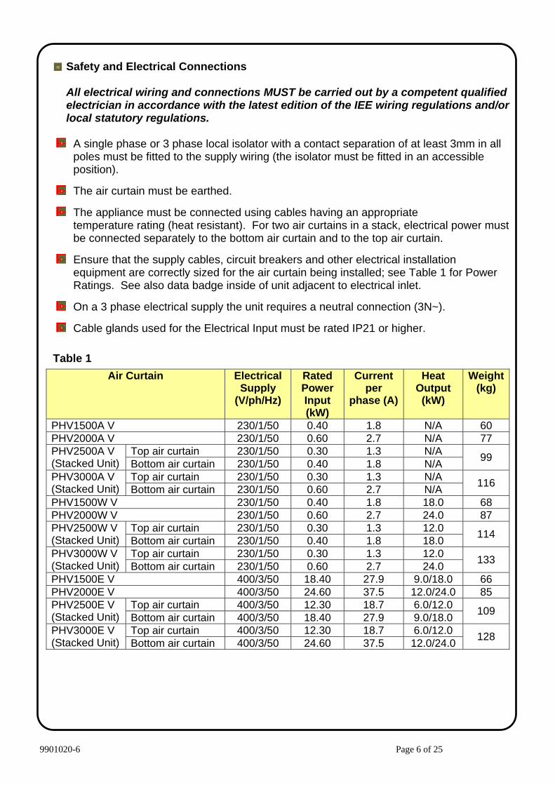
Safety and Electrical Connections
All electrical wiring and connections MUST be carried out by a competent qualified electrician in accordance with the latest edition of the IEE wiring regulations and/or local statutory regulations.
A single phase or 3 phase local isolator with a contact separation of at least 3mm in all
poles must be fitted to the supply wiring (the isolator must be fitted in an accessible position).
The air curtain must be earthed.
The appliance must be connected using cables having an appropriate
temperature rating (heat resistant). For two air curtains in a stack, electrical power must be connected separately to the bottom air curtain and to the top air curtain.
Ensure that the supply cables, circuit breakers and other electrical installation equipment are correctly sized for the air curtain being installed; see Table 1 for Power Ratings. See also data badge inside of unit adjacent to electrical inlet.
On a 3 phase electrical supply the unit requires a neutral connection (3N~).
Cable glands used for the Electrical Input must be rated IP21 or higher.
Table 1
Air Curtain Electrical Supply
(V/ph/Hz)
Rated Power Input (kW)
Current per
phase (A)
Heat Output (kW)
Weight(kg)
PHV1500A V 230/1/50 0.40 1.8 N/A 60 PHV2000A V 230/1/50 0.60 2.7 N/A 77
Top air curtain 230/1/50 0.30 1.3 N/A PHV2500A V (Stacked Unit) Bottom air curtain 230/1/50 0.40 1.8 N/A 99
Top air curtain 230/1/50 0.30 1.3 N/A PHV3000A V (Stacked Unit) Bottom air curtain 230/1/50 0.60 2.7 N/A 116
PHV1500W V 230/1/50 0.40 1.8 18.0 68 PHV2000W V 230/1/50 0.60 2.7 24.0 87
Top air curtain 230/1/50 0.30 1.3 12.0 PHV2500W V (Stacked Unit) Bottom air curtain 230/1/50 0.40 1.8 18.0 114
Top air curtain 230/1/50 0.30 1.3 12.0 PHV3000W V (Stacked Unit) Bottom air curtain 230/1/50 0.60 2.7 24.0 133
PHV1500E V 400/3/50 18.40 27.9 9.0/18.0 66 PHV2000E V 400/3/50 24.60 37.5 12.0/24.0 85
Top air curtain 400/3/50 12.30 18.7 6.0/12.0 PHV2500E V (Stacked Unit) Bottom air curtain 400/3/50 18.40 27.9 9.0/18.0 109
Top air curtain 400/3/50 12.30 18.7 6.0/12.0 PHV3000E V (Stacked Unit) Bottom air curtain 400/3/50 24.60 37.5 12.0/24.0 128

9901020-6 Page 7 of 25
To gain access for making electrical and/or water services the air intake grilles must be removed. Remove intake grilles by unfastening two screws on each grille; M4 x 10mm Pozi screws accessed via larger hole in the side of the grille (See Insert). Access can now be gained to make the electrical connections and assist with water connections.
When making electrical connections first remove the safety cover plates over the electrical supply terminals. On 2m electric air curtains the safety cover plates are located towards the centre of the air curtain (See Insert).
For two air curtains in a stack electrical and water connections are made separately to the bottom air curtain and to the top air curtain (See Figure 1 View B).
Fitting/Connecting the Ecopower Remote Control
The remote control unit should be located in a suitable place for easy access, it can be fixed to the wall via two key-hole slots. Drill and fix the screws into the wall leaving a small gap between the head and the wall, lower the unit onto the screws, for fixing centres see adjacent figure. Ensure suitable fixing screws are used. The remote control is supplied with cable and a pre-fitted RJ connecting plug.
Ensure the remote control cable is safely secured and connected to the air curtain as indicated. It can be plugged into either socket.
80mm
3.5mm
6mm
Safety cover plates

9901020-6 Page 8 of 25
RJ master/slave cable safely routed internally between circuit boards of top and bottom air curtains
Figure 2
Route master/slave cable via internal hole in stacking kit
Two Air Curtains in a Stack
When two air curtains are in a 2.5m or 3m stack the Ecopower control wiring needs to be wired “master/slave”, so the air curtain stack is controlled by a single Ecopower remote control. Plug the control cable from the remote control into one of the RJ sockets at the side of the top air curtain. Inside the air curtain stack connect the RJ master/slave cable that is already plugged into the top unit circuit board, into the Ecopower PCB of the bottom unit. Route the RJ master/slave cable safely via the hole in the stacking kit (Refer to Figure 2).

9901020-6 Page 9 of 25
A B
A/B
22mm pipe
22mm pipe
22mm pipe
15mm pipe
RETURN
FLOW
Upper water entry point shown for Right Hand air curtain
Alternative water entry points shown in dotted
A B
A/B
22mm pipe
22mm pipe
22mm pipe
15mm pipe
RETURN
FLOW
Optional 1m Stack Unit
Figure 3
LPHW Models
For LPHW models ensure suitable water mains isolation valves are fitted in the flow and return pipework. When fitting the 3-port valve ensure that the pipe connections are fitted as detailed and are in accordance with the manufacturers leaflet supplied with the valve. For two air curtains in a stack each air curtain requires a separate and independent water flow and return connection with its separate control valve (See Figure 3). Each control valve is wired to the terminal block in each air curtain (see wiring diagram for water heated units). In order to obtain optimum heat output, all air from the system and the heating coil must be vented. Refer to insert detailing the water coil air bleed valve.
Air Curtain Water Flow Rate (l/s) 82/72 °C
Coil Water Pressure Drop (kPa)
PHV1500W V 0.43 2.60 PHV2000W V 0.57 4.72
Top air curtain 0.29 1.14 PHV2500W V (Stacked Unit) Bottom air curtain 0.43 2.60
Top air curtain 0.29 1.14 PHV3000W V (Stacked Unit) Bottom air curtain 0.57 4.72
Air vent

9901020-6 Page 10 of 25
Ecopower Controller Motherboard (v8)
Function
Control
Comments
Standard
Fan Heat Interlock for Electric Heated Air Curtains– The heat output is dependent on the fan speed. If low or medium fan speed is selected the heat output can only go up to first heat stage. Only if the unit is operating on high fan speed can the second heat stage be selected. This feature operates in manual or auto mode.
DIP1
Maximum heat output achieved if maximum fan speed selected. Independently set-up DIP switch on each mother board.
Used to avoid excessive temperatures with electric heated air curtains.
As supplied, for electric heated air curtains the default setting for heat output would be dependent on fan speed (DIP1 ON).
For Ambient and LPHW heated air curtains default setting for DIP1 OFF.
Disable Fan Run-on for LPHW and Ambient Air Curtains – Disable fan run-on.
DIP2
Must only be used for LPHW and Ambient air curtains. Independently set-up DIP switch on each mother board.
As supplied, for Ambient and LPHW heated air curtains the default setting would disable fan run-on (DIP2 ON).
Thermostat Master – Only the air sensor thermistor in the master air curtain will be used for measuring the reference air temperature for the whole master/slave installation.
DIP3 Option
The air sensor thermistors in all the slave air curtains will be ignored. This will then avoid situations on larger doorways with master/slave air curtains where some units can blow cold air whilst others can blow warm air, because they currently all refer to their own air sensor for control of the heat output of each air curtain. The master air curtain need not be the one that the wall control is plugged into. This dip switch setting must also be used for Global Switching (Master/Slave) via the INHIBIT terminal – see next page.
As supplied, the default setting would be for the air sensor thermistor on all units to be measuring (DIP3 OFF).
Overheat Fan Disable – If DIP4 is on and thermal overheat trips, heat and fan circuits are isolated and LED’s on wall switch flash. If DIP4 is off and TOC trips out, only the heat circuit is isolated and the LED’s on the wall switch flash.
DIP4 Option (Electric only)
Wall switch upgrade required. The handset has to be powered on. Independently set-up DIP switch on each mother board. To remove fault, isolate electrical supply to air curtain, reset TOC and reconnect supply.
As supplied, the default setting would enable fan if TOC trips (DIP4 OFF). NB: If TOC operates with an upgraded switch the LED’s on switch flash, regardless of DIP4 settings.
Retain User Settings (toggle) – If electrical supply to the air curtain is removed, upon restoring electrical supply the customer’s settings on the remote control will be retained, i.e. if unit were operating beforehand, it would automatically start up again and operate on the exact same settings as before.
Optional feature –via secret key press (Fan-down)
Wall switch upgrade required. To toggle – switch unit on from handset. Hold Auto button till Auto LED flashes. Press fan down button to toggle selection.
As supplied, the default setting would be for the unit to start up again automatically. Need to do the secret key presses to revert back to “nothing happens” when power is restored, as we have it now.
Fan run-on time set two minutes. Built-in If “FAN ONLY” has been selected, at switch off, no fan run-on.
Reduce time for fan speeds to turn on and index up through Low, Medium and High fan speed when turning on via the BMS/Remote On/Off option.
Built-in
- white rectangle indicates the moveable head of each 4 way DIP switch
ON
OFF
1 2 3 4
ON
OFF
1 2 3 4
ON
OFF
1 2 3 4
ON
OFF
1 2 3 4

9901020-6 Page 11 of 25
DIP switches fitted on the Ecopower board provide a selection of optional features as described above. Isolate and switch electrical power off before configuring and/or changing any DIP switch settings.
• Easy plug-in arrangement for remote air sensor thermistor on a 1m lead. Plugging-in the remote air sensor to J3
disables the standard air sensor thermistor already fitted on the Ecopower board. As supplied, the board will not have the remote air sensor fitted.
• An INHIBIT two screw terminal fitted on the Ecopower board for BMS remote On/Off feature. If the terminal is linked, i.e. by 2 wires to a remote volt free contact, the unit will run. If it is open circuit across the terminal the unit will switch off. This remote On/Off feature has global switching logic, i.e. if you master/slave several units together you need connect the remote contact to only one of them to turn all units on and off in the master/slave system. For global switching to work on the slave units, need to set DIP3 Option (see previous page) on the unit that the remote contact is wired to and have previously turned the unit on with the wall switch. As supplied, a wire link will be fitted to the terminal block on every unit. For summer settings place a 3.3kΩ resistance across the INHIBIT terminal, with these settings fans only will run even if controller is requesting for heat.
ECOPOWER BOARD
Customer Building Management System
• A HEALTHY two screw terminal is included on the board for a fault signal indication if the electric elements overheat cut-out has operated. A healthy system provides a 24V DC signal at the terminals compared to an overheat fault which provides OV DC.

9901020-6 Page 12 of 25
9901020-6 Page 13 of 25

9901020-6 Page 14 of 25
9901020-6 Page 15 of 25

9901020-6 Page 16 of 25

9901020-6 Page 17 of 25

9901020-6 Page 18 of 25

9901020-6 Page 19 of 25

9901020-6 Page 20 of 25

9901020-6 Page 21 of 25

9901020-6 Page 22 of 25
Ecopower Remote Control Operation
Push On/Off switch to turn On, then operate as follows :-
Auto Switches between manual and automatic heat regulation. The Auto on indicator LED is lit for "Auto Mode" and un-lit for "Manual Mode".
On/Off Turns the air curtain On or Off (when turned off the settings for heat and fan speed are retained). If the air curtain is heating when it is turned off with this switch the fan will run-on for a time (approx. 2 minute) to dissipate excess heat.
Selects the appropriate fan speed (Low, Medium or High) to suit the air curtain height and outside wind conditions. Fan speed can be changed when unit is in either Auto or Manual Modes. A fan speed indicator LED shows which fan speed is selected.
In "Auto Mode” the air curtain measures the incoming air temperature and automatically selects the necessary amount of heat to keep it at the level selected. Heating level indicator LED's go from 0% to 100% in 8 steps to show the level selected. In "Manual Mode” heat output can be selected as Zero, Half Heat or Full Heat. Heating level indicator LED's go 0%, 50% or 100% to show the
level selected.
Push On/Off switch again to turn Off
Note If the mains supply is isolated or cuts-out during operation the On/Off switch will need to be pushed again to start the air curtain when the mains supply is restored. The safety thermal cut-out in the air curtain may operate, if this happens it will need to be reset by a competent technician.
Higher Heat
Lower Heat Lower Fan speed
Higher Fan Speed
On / Off
Auto Mode
Auto on Indicator Fan Speed Indicator
Heating Level Indicator

9901020-6 Page 23 of 25
Commissioning
Set the discharge grille vanes so they point straight across the doorway. Once the air curtain is functioning check that the fans operate at Low, Medium and High speeds, that there is no excessive mechanical noise coming from the fans and that all fans are working. If the unit is electric heated or water heated check that the air stream from the discharge grille warms up across the whole height of the air curtain when heating is selected. If there are two air curtains in a stack PHV2500V or PHV3000V ensure both units in the stack operate correctly as master/slave. Check that heating increases as higher heat is selected and feel to see that the warm air stream is reaching across the doorway with door open or closed. If necessary the vanes of the discharge grille can be angled either inwards or outwards if this gives better penetration/warming of any incoming draughts. For the Ecopower controller check all functions operate correctly in Manual Mode. Then select Auto Mode and increase the heating set point until the air stream warms up. Reduce the heating set point until the air stream goes cold.
Once functional tests have been completed and verified all electrical safety plates and intake grilles must be correctly refitted. The plastic cap should be clipped on the top of the air curtain (See Insert).
Before leaving site it is important that the air curtain installation and these instructions are “Handed-Over” to the end user or his representative and the operation of it is fully explained and that they understand how it operates. Explain also the service intervals and that the unit must be regularly cleaned.
Fault Conditions
In the event of a fault with electrical heated air curtains the thermal cut out(s) may operate. Note: If the mains supply is isolated during operation then the thermal cut outs may operate. The thermal cut out(s) are located within the unit adjacent to the electric elements (one on the 1m & 1.5m and two on the 2m model). There are two fuses on the Ecopower circuit board which may blow in the event of a fault. The Ecopower circuit board is located towards the top of each unit.
In the case of a fault condition (refer to flowchart) do not attempt to reset the thermal cut outs or replace the fuses. Arrange for a Thermoscreens appointed technician or certified electrician to attend the unit to investigate the reason why the thermal cut outs/fuse(s) have operated. Once the cause has been determined and rectified, they will reset/replace the thermal cut out/fuse and function test the unit.
PCB Status
Fitted on the PCB board inside of the air curtain is an LED shown as LED1 on wiring diagrams that will indicate the Ecopower control status.
1. LED flashing green – operation normal. 2. LED flashing red – low supply voltage. 3. LED permanently red – thermal cut outs open circuit (electrically heated models only).
Note to reset the thermal cut outs please refer to Fault Conditions section detailed above.

9901020-6 Page 24 of 25
User Fault Finding Flowchart (for Ecopower Control)
Yes
Unit is working satisfactorily
Switch on Electrical
Power
Connect remote control and push On/Off switch
to turn unit on
Select heat output
Contact Installer
Service Agent to investigate why
thermal cut-out(s) have operated
Service Agent to reset thermal cut-
out(s)
Contact Installer
Yes
No
Yes
Yes
No
No
No
Yes Yes
No
No
Is Electrical Power
switched on
Are the fans operating correctly
Is the unit discharging
warm air
Check if thermal cut-out(s) have tripped (Electric
Heated only)
Do the LED’s light up on the remote
control
Is the remote control
plugged in and turned
on

9901020-6 Page 25 of 25
Service & Maintenance
Always disconnect and isolate the mains electricity supply before installing, maintaining or repairing this equipment. With 2.5m or 3m vertical air curtains there are two air curtains, one stacked on top of the other. Isolate the mains supply to both top and bottom air curtains. Note: All maintenance/repairs should only be carried out by a competent electrician or Thermoscreens appointed technician. Once the mains supply is isolated, remove the plastic cap from the top of the air curtain. Remove each air intake grille by unfastening two screws on each grille – M4 x 10mm Pozi screws accessed via the larger hole at one edge of each grille. To ensure the air curtain operates at full efficiency the inlet/outlet grilles, fan impellers, housings and motors must be kept free of dust and debris. Build up of dust on the fan impellers can cause vibration, noise and excessive wear on the motor bearings. Frequency of cleaning will depend on the environment, but we would recommend that the unit be cleaned a minimum of every 3 months (failure to adequately maintain the unit and provide a suitable cleaning schedule will result in performance degradation and reduce the life expectancy of the air-curtain). Vacuum and clean the build-up of dirt and debris within the air-curtain (please note that the motor(s) are permanently lubricated and require no additional lubrication). Once the air curtain has been cleaned, remove appropriate electrical safety cover plates and check all electrical connections within the unit ensuring terminals are tight and that crimped connections have not become loose. Always ensure all safety cover plates are correctly refitted. Refit inlet grilles and plastic cap. Reconnect the electrical supply and fully function test the air-curtain to ensure correct operation (See Commissioning). If the outer casing requires cleaning this should be done using a warm soft cloth. Do not use solvents or abrasive materials.
Warranty
If any problems are encountered, please contact your installer/supplier. Failing this please contact the Thermoscreens warranty department. All units are covered by a two year warranty period. Care has been taken in compiling these instructions to ensure they are correct, although Thermoscreens disclaims all liability for damage resulting from any inaccuracies and/or deficiencies in this documentation. Thermoscreens retain the right to change the specifications stated in these instructions. Thermoscreens Ltd St. Mary’s Road Nuneaton Warwickshire England CV11 5AU Email: [email protected] Tel: + 44 (0) 24 7638 4646 Fax: + 44 (0) 24 7638 8578 www.thermoscreens.com