Photogrammetric Measurements for Rigid Body Movements in Low Speed Wind Tunnel Testing
7
American Institute of Aeronautics and Astronautics 1 Photogrammetric Measurements for Rigid Body Movements in Low Speed Wind Tunnel Testing Deepak M. Atyam 1 University of California San Diego, La Jolla, CA, 92092-0100 A new photogrammetry system manufactured by Vicon has been tested as a means of determining shape and dynamic behavior of a rotorcraft model in a low speed wind tunnel facility. The Vicon system is able to utilize a series of cameras to triangulate retro reflective targets in 3D space with a high degree of accuracy. The Vicon system is an off the shelf system, primarily in the entertainment industry, used to produce accurate 3D biomechanical reconstructions of human movements. It was created for the tracking of biomechanical operations but will be evaluated in this case for its accuracy in measurements of rigid body motion. A discussion of the utilization of the entertainment industry system for tracking rigid body deformation including the lighting, design, calibration, and testing process is included. The successful tests were conducted in the NASA Langley Research Center (LaRC) 14x22 Low Speed Wind Tunnel. I. Introduction HERE is considerable interest in accurately measuring the rigid body motion of a model in a low speed wind tunnel. Prototypes of many commercial vehicles are tested in low speed wind tunnels including aircraft, rotorcraft, and ground based vehicles. To accurately measure the model movement retro reflective targets provide the system a high contrast feature that allows the imaging system the ability to compute the spatial coordinates. The coordinates of each retro reflective target can be utilized to compute the vibration, frequency, and dynamic effects of a simulated flight during testing by calculating precise movements for each target. Experimental testing of wind tunnel models provides data that can be compared with computational fluid dynamics (CFD) predictions to help validate design geometries. These measurements can also be used to calibrate and validate other computational methods such as the finite element model (FEM). Static and dynamic deformations from wind tunnel tests are measured to predict full vehicle response and correct aerodynamic and aeroelastic analytical predictions. The LaRC 14x22 wind tunnel is a subsonic low speed wind tunnel with a 14 foot by 22 foot test section that is capable of reaching speeds up to 230 mph. The model is set in place before the test section is active. II. System Design Optical access is feasible from three out of four sides while testing in the LaRC 14x22 wind tunnel. Optical measurements can be made from either lateral side as well as the wall that is over the model. To meet aerodynamic testing requirements a three-camera video system was utilized to employ the basic principles of photogrammetry. The cameras that were utilized are the MX-F40 cameras created by Vicon Systems. 1 Undergraduate Student, Department of Mechanical and Aerospace Engineering, AIAA Student Member. . T (a) Vicon MX-F40 Cameras (b) 3 MX-F40 Cameras arranged in the 14x22 wind tunnel Figure 1. Vicon Systems MX-F40 Cameras Displayed
description
Placed 3rd place at the 2013 AIAA Student Conference Region VI. Conduct Photogrammetry research at Langley Research Center during the summer of 2012
Transcript of Photogrammetric Measurements for Rigid Body Movements in Low Speed Wind Tunnel Testing

American Institute of Aeronautics and Astronautics
1
Photogrammetric Measurements for Rigid Body Movements
in Low Speed Wind Tunnel Testing
Deepak M. Atyam1
University of California San Diego, La Jolla, CA, 92092-0100
A new photogrammetry system manufactured by Vicon has been tested as a means of
determining shape and dynamic behavior of a rotorcraft model in a low speed wind tunnel facility.
The Vicon system is able to utilize a series of cameras to triangulate retro reflective targets in 3D
space with a high degree of accuracy. The Vicon system is an off the shelf system, primarily in the
entertainment industry, used to produce accurate 3D biomechanical reconstructions of human
movements. It was created for the tracking of biomechanical operations but will be evaluated in
this case for its accuracy in measurements of rigid body motion. A discussion of the utilization of
the entertainment industry system for tracking rigid body deformation including the lighting,
design, calibration, and testing process is included. The successful tests were conducted in the
NASA Langley Research Center (LaRC) 14x22 Low Speed Wind Tunnel.
I. Introduction
HERE is considerable interest in accurately measuring the rigid body motion of a model in a low speed wind tunnel. Prototypes of many commercial vehicles are tested in low speed wind tunnels including aircraft,
rotorcraft, and ground based vehicles. To accurately measure the model movement retro reflective targets
provide the system a high contrast feature that allows the imaging system the ability to compute the spatial
coordinates. The coordinates of each retro reflective target can be utilized to compute the vibration, frequency, and
dynamic effects of a simulated flight during testing by calculating precise movements for each target. Experimental
testing of wind tunnel models provides data that can be compared with computational fluid dynamics (CFD)
predictions to help validate design geometries. These measurements can also be used to calibrate and validate other
computational methods such as the finite element model (FEM). Static and dynamic deformations from wind tunnel
tests are measured to predict full vehicle response and correct aerodynamic and aeroelastic analytical predictions.
The LaRC 14x22 wind tunnel is a subsonic low speed wind tunnel with a 14 foot by 22 foot test section
that is capable of reaching speeds up to 230 mph. The model is set in place before the test section is active.
II. System Design
Optical access is feasible from three out of four sides while testing in the LaRC 14x22 wind tunnel. Optical
measurements can be made from either lateral side as well as the wall that is over the model. To meet aerodynamic
testing requirements a three-camera video system was utilized to employ the basic principles of photogrammetry. The cameras that were utilized are the MX-F40 cameras created by Vicon Systems.
1 Undergraduate Student, Department of Mechanical and Aerospace Engineering, AIAA Student Member.
II. T
(a) Vicon MX-F40 Cameras (b) 3 MX-F40 Cameras arranged in the 14x22 wind tunnel
Figure 1. Vicon Systems MX-F40 Cameras Displayed

American Institute of Aeronautics and Astronautics
2
Photogrammetry is the science of measuring the size and location of a three-dimensional (3D) object by using
photographs. The ability to put a series of images together with references to their frequency of capture enables the
use of a technology referred to as “videogrammetry” (or “videometrics”) instead of “photogrammetry”. In this
situation targets were utilized in specified positions to help compute distances traveled in addition to computing the
accuracy of tracking the centroid of the targets. The targets were constructed with 3M 7610 reflective tape. The
targets on the rotorcraft were circular with a 0.5” diameter. The retro reflective tape, which is 0.004” thick, serves as a beacon by sending back the Near Infrared (NIR) light that is transmitted back at a luminance factor of 900X.
The measured set of points can be used to characterize shape and position. To triangulate the targets, the
images are processed to determine the 3D coordinates of the points to calculate the intersection of the light rays. An example of the setup system can be seen in Figure 3.
While performing lab test with the Vicon MX-F40 cameras, it was observed that a minimum diameter of 8-
10 pixels on the image plane was necessary to obtain accurate data. By understanding that the larger the iris enables
more light, it is apparent that there is an increase in the amount of noise for the subject capture. The 4 Megapixel
Figure 2. Circular 3M 7610 Reflective tape targets on rotorcraft model
Figure 3. 3M 7610 Reflective tape targets on rotorcraft model

American Institute of Aeronautics and Astronautics
3
Figure 4. Scale Bar on Translation Stage mounted on Tripod
Figure 5. L-Frame and Calibration
Wand for Vicon System
Vicon MX-F40’s were configured with a 25mm Fujinon lens to obtain the optimal resolution for the desired field of
view (FOV). The cameras have a user selectable frame rate, for this test the acquisition rate was set at 200 Hz.
To ensure the highest accuracy for the system the cameras were placed at separate heights and distances
from each other to ensure that the targets are being triangulated from the entire volume of the Nexus program. It is
optimal to keep the cameras at a maximum of 55° from the alpha of the target. Alpha is the angle that is measured
from the difference of the incoming ray from the normal of the target. The reason for keeping the cameras at a minimum of 55° from the alpha of the target is because the 7610 tape’s retro reflectivity decreases exponentially for
angles past 55° from the normal.
For portability and ease of use the cameras were mounted to an
extruded aluminum frame on the outer walls of the wind tunnel.
The aluminum materials are available from 80/20 Inc. and provide
the system designer with a lot of options for hardware mounting. A
predesigned camera mounting system was not utilized. Instead, a
custom mount created from raw 80/20 extrusions was used to hold
the cameras. To maintain the integrity of the calibration the frame
supporting the cameras were very rigid to ensure the cameras are
not moving as a result of vibration induced from the tunnel
operation.
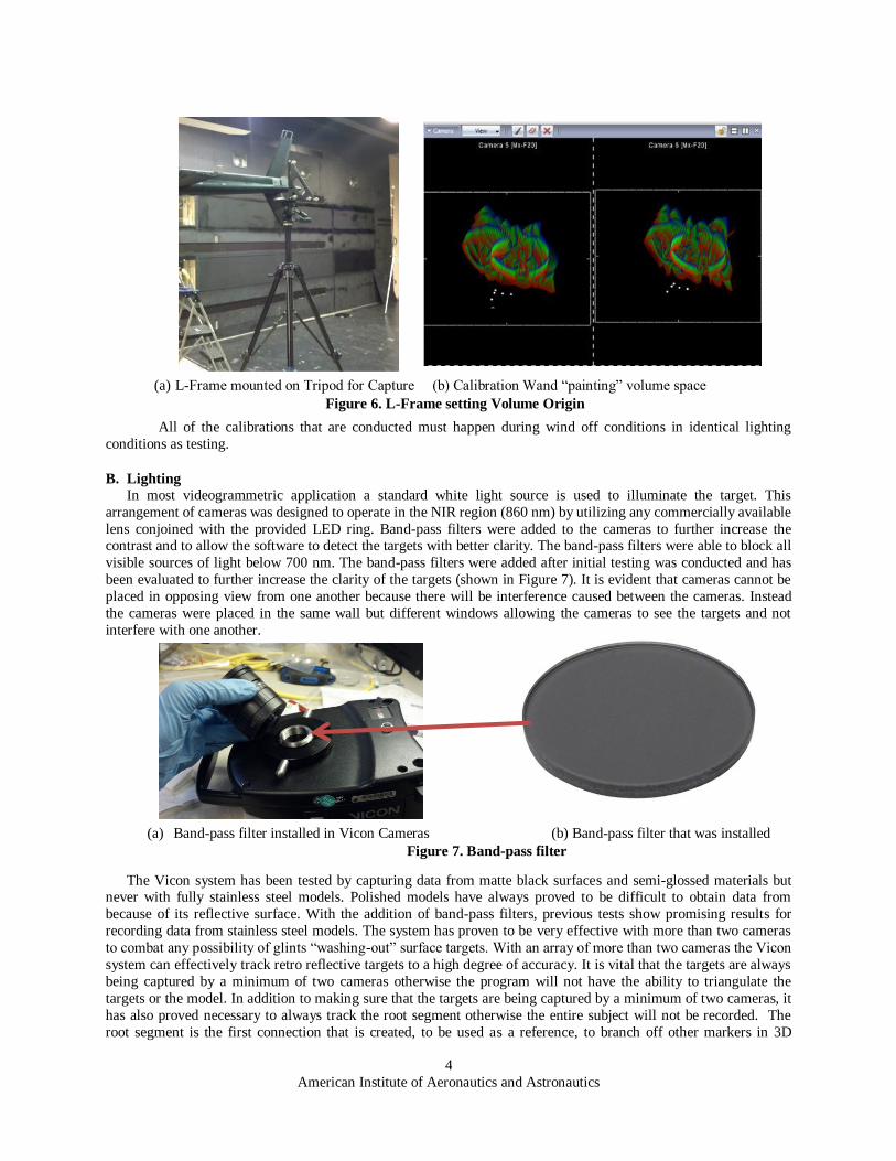
A. Calibration
Calibration is of critical importance with any measurement
system to make sure that the system is performing consistently and
taking measurements accurately. The general technique for
calibrating a volume space, with this Vicon system, is to use a
series of recorded images from multiple perspectives with objects
of known size and spacing with a software package called Nexus. By obtaining a series of images in the Nexus
software the program is able to perform a camera calibration which utilizes the known size and spacing of the retro
reflective targets in reference to one another to account for lens distortion and unify all of the cameras to a set volume of data capturing. In order to calibrate the system, all cameras must have the Calibration Wand in their field
of view to capture the movements. The Calibration Wand is an object
with retro reflective spheres set a specific distances used to calibrate the
volume that the cameras can capture. The Calibration Wand and L-
Frame are shown in Figure 5.
The Nexus software is able to detect the Calibration Wand as it
covers the volume space in which the targets are located in. The wand
fundamentally “paints” a volume space to visually show the user what
regional area is being calibrated in reference to the wand’s position. By
using a wand with retro reflective targets of known size and spacing in
relation to one another the Nexus software is able to using captured data
to calibrate the cameras to record accurate data in the set volume space.
After calibrating the cameras the program is able to set a
defined axis of origin using an L-Frame with specified sizes of the
retro reflective targets along with referenced distances from one
another, similar to the calibration wand. The axis of origin, a specified point in the volume space, is referred to as a
volume origin through the Nexus software. By setting a volume origin, for all cameras to reference, that one point in
space serves as the basis for all measurements made using the Nexus software until a new volume origin is set.
American Institute of Aeronautics and Astronautics
4
All of the calibrations that are conducted must happen during wind off conditions in identical lighting
conditions as testing.
B. Lighting
In most videogrammetric application a standard white light source is used to illuminate the target. This
arrangement of cameras was designed to operate in the NIR region (860 nm) by utilizing any commercially available
lens conjoined with the provided LED ring. Band-pass filters were added to the cameras to further increase the contrast and to allow the software to detect the targets with better clarity. The band-pass filters were able to block all
visible sources of light below 700 nm. The band-pass filters were added after initial testing was conducted and has
been evaluated to further increase the clarity of the targets (shown in Figure 7). It is evident that cameras cannot be
placed in opposing view from one another because there will be interference caused between the cameras. Instead
the cameras were placed in the same wall but different windows allowing the cameras to see the targets and not
interfere with one another.
The Vicon system has been tested by capturing data from matte black surfaces and semi-glossed materials but never with fully stainless steel models. Polished models have always proved to be difficult to obtain data from
because of its reflective surface. With the addition of band-pass filters, previous tests show promising results for
recording data from stainless steel models. The system has proven to be very effective with more than two cameras
to combat any possibility of glints “washing-out” surface targets. With an array of more than two cameras the Vicon
system can effectively track retro reflective targets to a high degree of accuracy. It is vital that the targets are always
being captured by a minimum of two cameras otherwise the program will not have the ability to triangulate the
targets or the model. In addition to making sure that the targets are being captured by a minimum of two cameras, it
has also proved necessary to always track the root segment otherwise the entire subject will not be recorded. The
root segment is the first connection that is created, to be used as a reference, to branch off other markers in 3D
(a) L-Frame mounted on Tripod for Capture (b) Calibration Wand “painting” volume space
Figure 6. L-Frame setting Volume Origin
(a) Band-pass filter installed in Vicon Cameras (b) Band-pass filter that was installed
Figure 7. Band-pass filter

American Institute of Aeronautics and Astronautics
5
space, shown in Figure 8. Complex geometries should not adversely affect the quality of the subject capture as long
as all of the targets can be seen during the entire capture process.
III. Integration and Testing
The goal of the work is to test whether the system is reliable and accurate during certain conditions while
being tested in a wind tunnel. A few methods were derived to conduct the testing but ultimately concluded in
utilizing scale bars in a static wind tunnel. The scale bars have accuracy to .001” and were utilized with retro
reflective targets at known positions to determine the accuracy of the system during motion capture.
The tests were conducted in the 14x22 LaRC wind tunnel through .24” glass under wind off conditions.
The reason why these tests were conducted in a wind off condition was due to the movements in the model during
wind on tests. It was calculated that the system is responsive to vibrations and movements up to .0009”, thus
movements with the model have been noted during wind on conditions and measurements would prove to be too
noisy. The only way to get an accuracy reading of the system itself is to conduct the test during wind off conditions.
The scale bar tests were conducted by capturing movements of a scale bar on a translation stage with a resolution to
.001” (Shown in Figure 9). The Nexus software was able to capture the final resting points of the targets after the 1”
translations. By using the Pythagorean Theorem the points can be triangulated to calculate the total distance traveled
Figure 9. Scale bar with targets on translation stage
1 2 4 5
3
Figure 8. Root segment seen in the Nexus Software

American Institute of Aeronautics and Astronautics
6
instead of assuming that the scale bar was being translated perpendicular to the volume origin. The volume origin is
a point in 3D space that was set during the calibration of the system. C = Total distance traveled.
The scale bar was captured at a zero point, then moved exactly 1” on the translation stage in a lateral direction and then captured again. This process was repeated a total of 8 times with 5 second captures recording
each 1” translation. By triangulating the position the total translation distance is verified therefore validating the
system to a degree of accuracy of .0009”.
In addition to tracking 1 target and verifying that the target is being triangulated to move 1”, the scale bar allows
the opportunity to triangulate the targets on both sides of the scale bar. The scale bar, created from Invar, has an
extremely low coefficient of thermal expansion making it a great tool for recording precise measurements. The scale bar is exactly 23 inches from the center of targets number 2 to 4 and 25” from the center of
targets 1 and 5. By utilizing this known distance, it has been verified that the software is able to precisely track the
centroid of a target to a degree of accuracy of .04” in the scale bar configuration.
Figure 10. Data from a capture highlighting the accuracy of the translation recorded
Figure 11. Data from a capture highlighting accuracy of finding the centroid of a target

American Institute of Aeronautics and Astronautics
7
IV. Conclusion
The investigation and validation of Vicon Systems Cameras with the Nexus software for use of rigid body
motion in low speed wind tunnels has been presented. Many important aspects of the system design have been
explored and addressed. The lighting, camera calibration, and accuracy of the system have been investigated and
confirmed to an acceptable performance when compared with other photogrammetric techniques. The operational
capability of the system has been tested in laboratory, wind off, and wind on conditions.
Vibrations were not accounted in these calculations due to the fact that the cameras were not able to
accurately measure the retro reflective target on the opposing wall because of an insufficient light source and
environmental factors that drastically reduced the amount of emitted light to return to the camera. In addition to
accounting for the environmental factors it was noted that the vibration in the wall created an identical structured movement within all cameras so it did not cause a loss in a triangulated solution.
While testing, problems that dealt with the loss of targets occurred due to noise in the cameras. These
problems were quickly corrected with the use of ban-pass filters that blocked all light below 700 nm. Due to the use
of the band-pass filters the targets appeared as a higher contrast object through the system so the program was able
to easily identify all the targets.
It was measured that the Vicon system array had the ability to accurately measure the movement of an
object to .0009”. Even with this high of an accuracy of the transposition of the target it was calculated that the array
was only able to measure the centroid of a target to .04”. This data did not fit with the results of the transposition.
This is a bias error due to a number of reasons including mating surfaces along with a minuscule soiling of threads.
There are a variety of reasons why there is a bias error which is justified by continuous use, utilization in soiled
environments, as well as random errors. It was systematically measured that the centroid of the target was at an offset by .04” during the testing period which consisted of over 20 tests. Due to this error, the array is only validated
to .04” for the targeting of the centroid. This number is not the main piece of data though. When recording
movements, the centroid of the target is being utilized to verify that there is a high contrast marker at that point in
volume space. Even if the system were to not accurately measure the centroid, the movements of the targets are
being recorded to an accuracy of .0009” which is what matters during the testing.
Even though the entertainment system has not been fully integrated into Langley’s 14x22 foot wind tunnel,
the validation of the system demonstrates the capabilities of the utilization in the future. The design of the system
does not interfere with the models, in any intrusive fashion, other than the .004” thin retro reflective targets. It was
only necessary to calibrate the system once a day. Despite being an off the shelf entertainment industry product,
these are promising results for the utilization of this system in low speed wind tunnel tests.
Acknowledgments
I would like to thank Thomas W. Jones for being my mentor during my time as a Langley Aerospace
Research Student Scholar. Without him I would not be able to have completed my project and learned an incredible
amount from my experience. Charles B. Lundsford was also a large help to me when completing this research and I am fortunate he was able to sacrifice much of his time to assist me. I would also like to thank the Education
Department at NASA Langley Research Center for giving me the opportunity to conduct this research.
References
1Graves, Sharon S., and Alpheus W. Burner. Development of an Intelligent Videogrammetric Wind Tunnel Measurement
System. Tech. NASA Langley Research Center, n.d. Web. 2 Oct. 2012.
<http://ntrs.nasa.gov/archive/nasa/casi.ntrs.nasa.gov/20040086082_2004090457.pdf>. 2 Barrows, Danny A. Videogrammetric Model Deformation Measurement Technique for Wind Tunnel Applications. Tech.
AIAA/ NASA Langley Research Center, n.d. Web. 2 Oct. 2012. <http://ntrs.nasa.gov/archive/nasa/casi.ntrs.nasa.gov/20070003495_2007002900.pdf>. 3 Jones, Thomas W., and Charles B. Lunsford. Design and Development of a Real-Time Model Attitude Measurement System
for Hypersonic Facilities. Tech. AIAA/ NASA Langley Research Center, n.d. Web. 2 Oct. 2012. <http://archive.org/details/nasa_techdoc_20050060678>. 4"Scotchlite High Gain Reflective Sheeting 7610." Product Catalog 3M US:Â Scotchlite High Gain Reflective Sheeting 7610.
N.p., n.d. Web. 02 Oct. 2012. <http://solutions.3m.com/wps/portal/3M/en_US/Converter_Solutions/Home/Prod_Info/Prod_Catalog/?PC_7_RJH9U5230GE
3E02LECIE20GER4000000_nid=CQD8DPFK87be1BGS6T8P60gl>.