Phone: 907/777-8300 907/777-8300 Fax: 907/777.-8301 April 26, 2016 ... API 650 Welded Steel Tanks...
39
Hilcorp Alaska, LLC 3800 Centerpoint Drive Suite 1400 Anchorage, AK 99503 Phone: 907/777-8300 Fax: 907/777.-8301 April 26, 2016 Chris Hoidal Director, Western Region U.S. Department of Transportation Pipeline and Hazardous Materials Safety Administration 12300 W. Dakota Avenue, Suite 110 Lakewood, Colorado 80228 Re: CPF 5-2016-7002M Attached please find Hilcorp Alaska LLC’s amended procedure P-195.561 External Corrosion in response to NOA CPF 5-2016-7002M regarding the North Star Sales Oil Pipeline in Prudhoe Bay, Alaska. Please feel free to contact me at (907) 777-8430 or [email protected] if further information is needed. Sincerely, HILCORP ALASKA, LLC Erin McKay Regulatory Compliance Manager Alaska Integrity Group Enclosures cc (e-mail): Donald T. Johnson (PHMSA) Mr. Richard Novcaski, Vice President and Alaska Operations Manager Harvest Alaska, LLC Digitally signed by Erin M McKay DN: cn=Erin M McKay, c=US, o=Hilcorp Alaska LLC, ou=Facilities Engineering, [email protected] Date: 2016.04.26 16:36:10 -08'00' Erin M McKay
Transcript of Phone: 907/777-8300 907/777-8300 Fax: 907/777.-8301 April 26, 2016 ... API 650 Welded Steel Tanks...
Hilcorp Alaska, LLC3800 Centerpoint DriveSuite 1400Anchorage, AK 99503
Phone: 907/777-8300Fax: 907/777.-8301
April 26, 2016
Chris HoidalDirector, Western RegionU.S. Department of TransportationPipeline and Hazardous Materials Safety Administration12300 W. Dakota Avenue, Suite 110Lakewood, Colorado 80228
Re: CPF 5-2016-7002M
Attached please find Hilcorp Alaska LLC’s amended procedure P-195.561 External Corrosionin response to NOA CPF 5-2016-7002M regarding the North Star Sales Oil Pipeline in PrudhoeBay, Alaska.
Please feel free to contact me at (907) 777-8430 or [email protected] if further informationis needed.
Sincerely,
HILCORP ALASKA, LLC
Erin McKayRegulatory Compliance ManagerAlaska Integrity Group
Enclosurescc (e-mail): Donald T. Johnson (PHMSA)
Mr. Richard Novcaski, Vice President andAlaska Operations Manager Harvest Alaska, LLC
Digitally signed by Erin M McKayDN: cn=Erin M McKay, c=US,o=Hilcorp Alaska LLC, ou=FacilitiesEngineering,[email protected]: 2016.04.26 16:36:10 -08'00'
Erin MMcKay


Hilcorp Alaska Liquid Operations & Maintenance ManualP-195.561: External Corrosion
April 5, 2016
2 of 38
corrosion control?49 CFR 195.563 Which pipelines must have cathodic protection?49 CFR 195.567 Which pipelines must have test leads and how do I install
and maintain the leads?49 CFR 195.571 What criteria must I use to determine the adequacy of
cathodic protection?49 CFR 195.573 What must I do to monitor external corrosion control?49 CFR 195.575 Which facilities must I electronically isolate and what
inspections, tests and safeguards are required?49 CFR 195.577 What must I do to alleviate interference currents?49 CFR 195.585 What must I do to correct corroded pipe?49 CFR 195.588 What standards apply to direct assessment?
Forms
F-195.422 Leak Investigation / Repair and Exposed Pipe and ForeignCrossing Report
F-195.561 Cathodic Protection InstallationF-195.573 External Corrosion Control Monitoring
RelatedSpecifications
API 1162 Public Awareness Programs for Pipeline OperatorsAPI Spec. 12F Specification for Shop-Welded Tanks For Storage Of
Production LiquidsAPI 650 Welded Steel Tanks for Oil Storage, Including Addenda 1-3API RP 651 Cathodic Protection of Aboveground Petroleum Storage
TanksASME/ANSE B31G Manual for Determining the Remaining Strength of
Corroded PipelinesNACE RP-0169-96 Control of External Corrosion on Underground or
Submerged Metallic Piping Systems
OQ Covered TaskList
CT1--Conducting Cathodic Protection SurveysCT1.1--Measuring structure-to-soil PotentialsCT1.2--Conduct Close Interval SurveysCT1.3--Test to Detect InterferenceCT1.4-- Inspect and perform electrical test of bondsCT1.5-- Inspect and test isolation deviceCT2--Maintain Test LeadsCT2.1--Inspect and verify test lead continuityCT2.2--Repair damaged test leadsCT2.3--Install test lead by non-exothermic welding methodsCT2.4Install test leads by exothermic welding methodsCT3-- Inspect Rectifier (Obtain Voltage and Current output reading from rectifier
to verify proper performance)CT4-- Maintain and Repair RectifierCT4.1--Troubleshoot rectifier
Hilcorp Alaska Liquid Operations & Maintenance ManualP-195.561: External Corrosion
April 5, 2016
3 of 38
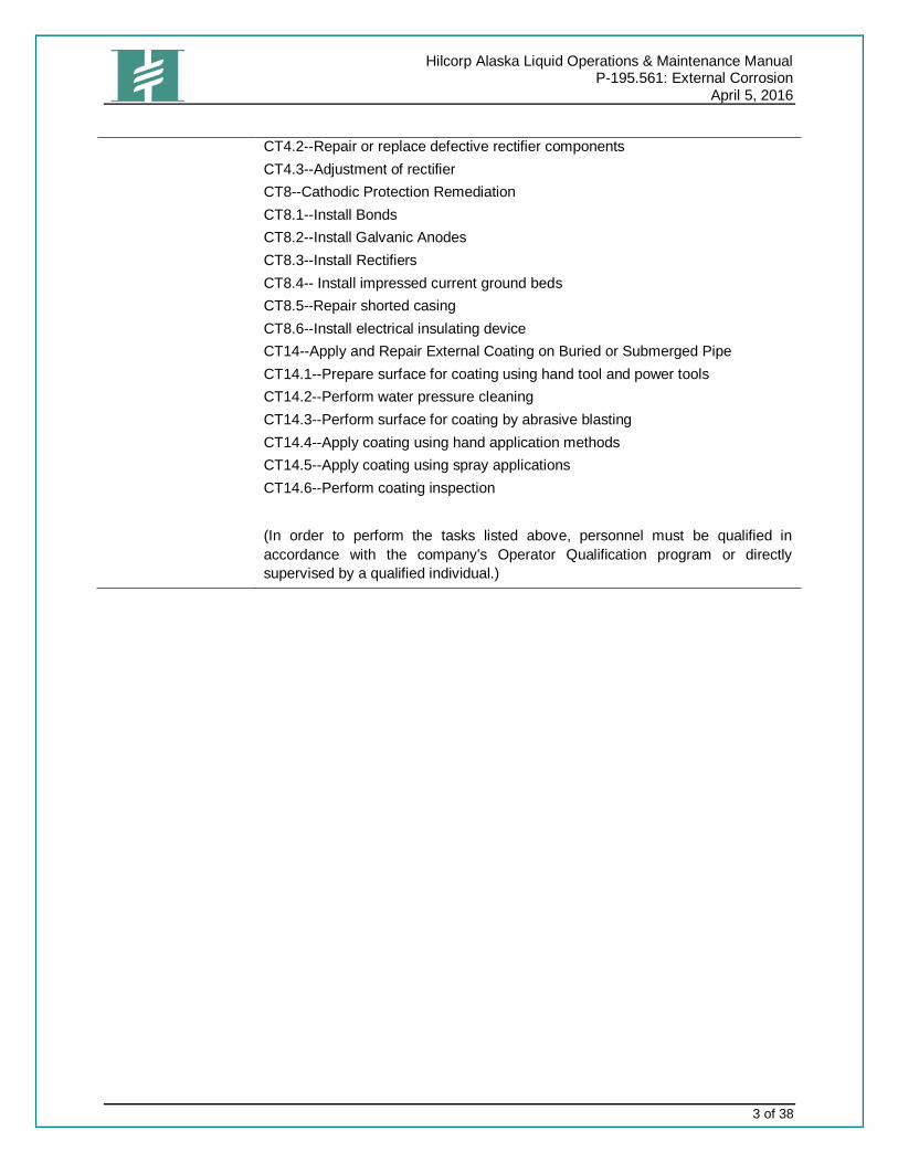
CT4.2--Repair or replace defective rectifier componentsCT4.3--Adjustment of rectifierCT8--Cathodic Protection RemediationCT8.1--Install BondsCT8.2--Install Galvanic AnodesCT8.3--Install RectifiersCT8.4-- Install impressed current ground bedsCT8.5--Repair shorted casingCT8.6--Install electrical insulating deviceCT14--Apply and Repair External Coating on Buried or Submerged PipeCT14.1--Prepare surface for coating using hand tool and power toolsCT14.2--Perform water pressure cleaningCT14.3--Perform surface for coating by abrasive blastingCT14.4--Apply coating using hand application methodsCT14.5--Apply coating using spray applicationsCT14.6--Perform coating inspection
(In order to perform the tasks listed above, personnel must be qualified inaccordance with the company’s Operator Qualification program or directlysupervised by a qualified individual.)


Hilcorp Alaska Liquid Operations & Maintenance ManualP-195.561: External Corrosion
April 5, 2016
5 of 38
PROCEDURE STEPS
Cathodic ProtectionPer DOT 49 CFR 195.563, each buried or submerged pipeline that is constructed, replaced or otherwisechanged must have cathodic protection that is in operation no later than one (1) year after theconstruction, replacement or change.
Each buried or submerged pipeline converted under 49 CFR 195.5 for use in transporting hazardousliquids must have cathodic protection if the pipeline:
· Has cathodic protection that substantially complies with one or more applicable criteria containedin paragraphs 6.2 and 6.3 of NACE SP0169; and/or
· Is a segment that is relocated, replaced or substantially altered.
All other buried or submerged pipelines that have an effective external coating1 must also have cathodicprotection. This requirement does not apply to breakout tanks, and does not apply to buried piping inbreakout tank areas and pumping stations until December 29, 2003.
Bare pipelines, breakout tank areas, and buried pumping station piping must have cathodic protection inplaces where regulations in effect before January 28, 2002 (i.e. previous editions of this part in 49 CFRparts 186 through 199) required cathodic protection as a result of electrical inspections.
Unprotected pipeline must have cathodic protection if a three or five-year re-evaluation (required under 49CFR 195.573(b)) indicates cathodic protection is warranted.
Note: The procedure steps listed below are the minimum required to meet regulatory compliance. Projectspecific instructions or Facility specific manuals may require more detailed data collection or reportingrequirements. These reporting requirements should be verified with the Facility Engineers, ProjectManagers and Regulatory Compliance Specialists to insure all necessary information will be collected.
Supervisor Qualifications (§195.555)Personnel who perform and/or supervise corrosion control activities shall be qualified by training, industrycertifications and/or previous experience prior to engaging in the practice of corrosion control for externalcorrosion. Hilcorp management is responsible for ensuring that the qualifications of those who overseeand direct corrosion control activities are adequate and appropriate for the type of work being performedfor hazardous liquids in transportation established under Title 49: Part 195 -Subpart H-Corrosion Control.If Hilcorp does not have qualified personnel, they may utilize the services of a competent, qualifiedcontractor or consultant. Qualified supervisors shall take prompt remedial action to correct anydeficiencies observed during cathodic protection monitoring and determine the appropriate repairsrequired.
1 A pipeline does not have an effective external coating if the current required to cathodically protect the line is the same as if theline was bare.

Hilcorp Alaska Liquid Operations & Maintenance ManualP-195.561: External Corrosion
April 5, 2016
6 of 38
External Corrosion Design ConsiderationsStructure design should include but not be limited to corrosion control considerations and cathodicprotection current requirements in the following sections. Refer to local engineering and constructionstandards manuals and typical drawings for additional details.
Electrically isolate the pipeline from all the following points, except where the pipeline is electricallyinterconnected with a structure and both are cathodically protected as a single unit or where the pipelineis intentionally bonded to mitigate interference currents:
· Shipper/customer and other mechanically interconnected pipelines at changes in ownership;
· Metallic casings and wall sleeves;
· Metal buildings and foundation steel;
· River weights;
· Valve enclosures (metallic buried valve boxes);
· Pipeline bridges;
· Other foreign metallic structures; and
· Anywhere electrical isolation is required to facilitate applying cathodic protection.
Note: Avoid installing insulating devices in areas containing a combustible or explosive atmospherewithout taking precautions to prevent arcing.
Consider the following when designing for external corrosion:
· Induced A/C current while operating in power line rights-of-way;
· Shielding;
· Other foreign cathodic protection systems near the facility; and
· Protect pipelines and insulating devices from fault currents and lightning with grounding anodesand fault current mitigation devices such as solid state surge suppressors.
Electrical Isolation
Electrical isolation may be attained by:
1. Flange insulation: Mating standard raised face flanges may be made into an insulating deviceby installing an insulating kit in the flange. An insulating kit consists of an electrically non-conductive gasket, non-conductive sleeves to encase the studs, and non-conductive washersfor both nuts of a stud. Steel washers should also be placed immediately under nuts to protectthe insulating washer from being crushed during torquing. When welding the insulating flangeunit or the weld type insulated coupling into the line, care shall be exercised to be sure that theinsulation is not damaged by the current “arc” which could occur from welding. This can beachieved by moving the ground cable to the same side of the flange set as the electrode cablethus eliminating current “arc” across the insulating flange during welding.
2. Monoblock insulating joints: Monoblock insulating joints are factory-assembled insulatingassemblies that are welded into a pipeline; they have no serviceable parts.
Hilcorp Alaska Liquid Operations & Maintenance ManualP-195.561: External Corrosion
April 5, 2016
7 of 38
3. Insulated unions: Insulating unions are usually used for small diameter (3” or less) pipingattachments that required electrical insulation.
4. Casing centralizers and end seals: Non-conductive centralizing devices are attached topipelines where the carrier pipe passes through a cased crossing. These centralizers preventelectrical contact between the casing and the carrier pipe. Casing end seals prevent water orsoil from entering the annular space between the carrier pipe and casing and causing an“electrolytic” short between the casing and pipe.
5. Other devices: Frequently, high-pressure laminated (e.g., micarta) dielectric blocks orneoprene rubber pads are used to electrically isolate a pipeline from supports or other structuralappurtenances which are not a part of the cathodically protected pipeline.
Test Stations and Other Contact Points
Provide sufficient test stations or other contact points for electrical measurements to determine if cathodicprotection is adequate.
Test points include test leads, valves, taps, meters, risers and other aboveground piping and shouldgenerally be no more than one mile apart. Install corrosion control test leads at:
· Pipe casings;
· Foreign metallic structure crossings, if practical; and
· Buried insulating joints (install insulating joints above ground when practical).
These factors are important when selecting test point locations:
· Land use;
· Accessibility;
· Distance from other test points;
· Population density;
· Pipe coating condition and pipeline current demand;
· Problem areas indicated by close interval survey data; and
· Span length test stations.
The following may also be used in conjunction with test stations:
· Cathodic protection determining coupons; and
· Permanent reference electrodes.
Attaching Test Leads
1. Exothermic welding shall be carried out by personnel proficient in using the equipment andrequirements of this specification to produce satisfactory results. Personnel conducting thermitewelding shall perform a satisfactory cable-to-pipe demonstration weld (on a sample pipe),witnessed by a Hilcorp representative, prior to welding to product piping.
2. Connect structure leads to piping
Hilcorp Alaska Liquid Operations & Maintenance ManualP-195.561: External Corrosion
April 5, 2016
8 of 38
3. Do not make connections within 6 inches of pipe girth welds or in areas of visible corrosion metalloss. Maintain at least 1 inch of spacing from longitudinal pipe welds. Leads shall be separated byat least 24 inches on piping.
4. Prepare the connection area by removing any existing coatings using a knife or scraper. Cleanthe area to bare metal. Remove an approximately 3” x 3” square area of coating and feather theedges (do not exceed 4” x 4” in exposed metal). File with a coarse file or rasp, or grind with adisc grinder and flexible disc to bright metal. Brushing the surface is not sufficient. Do not useresin-based sanding disks. Remove only the amount of metal necessary to achieve a clear, cleanarea.
5. Cut cable ends using a cable cutter to minimize deformation. Remove jacketing from the end toallow for insertion into the mold. Do not remove more that will be covered by the encapsulation.The conductor must be clean and dry to ensure a good weld. If the conductor end is wet andmuddy, heat the conductor using a torch to remove all moisture. Wiping while heating helps toremove mud. Next, rap the conductor to remove as much dirt as possible. Finally, wire brush theconductor ends to remove any remaining dirt and oxidation.
6. Verify that the correct mold type is being used. Ensure the mold used is clean, dry and in goodcondition. Confirm the following items:
a. The conductor fits snugly in the cable opening (preventing leakage), and the opening isnot chipped or worn out of round.
b. The weld cavity is well-defined, with no chips or gouges.c. The tap hole is well-defined.d. The disk seat is not worn or chipped, and allows the disk to seat properly.e. The mold parting face is not chipped, and has been cleaned properly using a towel or
cloth since the last use. Do not use a wire brush to clean this face.
7. Heat the mold before using for the first time each day. The mold may be dried by heating toaround 250° F with a torch.
8. Preheat the open mold with a torch to a maximum of 150° F. Place cable end into the mold.Close and lock the mold. Insert the metal disk (concave side up) in the weld metal cavity,covering the tap hole. Prepare the mold with the appropriate charge size (provided in section2.04). Substitutions are not permissible.
9. To ensure the base metal is dry, preheat the base material to 70-150° F using a torch. Next,gently set the mold on the base metal. When ready, hold the mold steady and ignite the startingmaterial using a flint igniter. Never use a match or lighter for igniting the charge. Lightly tap themold with the igniter while it is burning to help produce a more uniform weld.
10. Wait approximately 40 seconds for the reaction to complete, the weld to solidify, and the weld tocool. Open and remove the mold.
11. Examine the weld visually and by impact testing to ensure that it is acceptable.a. Visual Examination: Visually confirm that the weld is free of excessive slag, and is
reasonably smooth and porosity free. Excessive porosity is usually due to contaminantssuch as dirt, water and oil. Reject and replace the weld if slag deposits cover more than20% of the connection surface; if cable strands are exposed after slag removal; if a 1/32-inch diameter wire (paper clip) can penetrate a surface pinhole beyond the center of the

Hilcorp Alaska Liquid Operations & Maintenance ManualP-195.561: External Corrosion
April 5, 2016
9 of 38
conductor; or if the any portion of the conductor within the normal confines of the weld isexposed.
b. Impact Test: Impact test the connection to determine mechanical integrity using a metalor plastic hammer (1-2 lbs). Tap the base of the weld to confirm proper bonding. If theconnection moves or breaks free, reject the weld and repeat the weld process.
12. Remove rejected welds by grinding, minimizing removal of the base metal. Do not reweld within 6inches of a prior weld location. Consult Engineering for coating instructions for areas of exposedmetal due to rejected welds.
13. Encapsulate the completed cable connection using a Royston Handy Cap IP encapsulation (4” x4”), or a Handy Cap XL IP (5” x 5”). These encapsulations employ an integrated primer and donot require further priming. Install the encapsulation per the manufacturer’s instructions. Consultthe on-site Field Engineer if the “XL” encapsulation is not large enough to cover the exposedarea.
14. Prior to backfilling, perform a pipe-to-soil survey.
15. Backfill without disturbing the test station or wires.
16. Install post or pole with station attached directly above the pipeline. Do not connect the post orpole directly to the pipeline.
17. If more than one pipeline is monitored at this test station, attach permanent labels designatingeach pipeline to the appropriate station terminals and wires.
18. Add test station number and location to the most recent annual survey and map.
19. Distribute revised maps as required.
Applying External Coatings
1. Identify section to be coated. Coat all external surfaces. When evaluating existing coating,repair any locations where the coating is not well bonded to the substrate or has visible gaps.
2. Identify existing coating type, if previously coated.
3. Determine type of coating to be applied. Coating must:
a. Be designed to mitigate corrosion of the buried or submerged pipe;
b. Have sufficient adhesion to the metal surface to prevent under film migration of moisture;
c. Be sufficiently ductile to resist cracking;
d. Have enough strength to resist damage due handling and soil stress;
e. Support any supplemental cathodic protection; and
f. If the coating is an insulating type, have low moisture absorption and provide highelectrical resistance.
4. Obtain the necessary tools, materials, and safety equipment.
5. If pipeline was previously coated, remove damaged coating on existing pipe.

Hilcorp Alaska Liquid Operations & Maintenance ManualP-195.561: External Corrosion
April 5, 2016
10 of 38
6. Prepare surface for coating application according to coating manufacturer’s specification. Makeall practical efforts to dry the pipe before applying coatings or primers. Never apply coatingswhen the steel surface is wet unless the coating is designed to be applied to wet surfaces asspecified in the coating manufacturer's application instructions. Review the recommendedcleaning and surface preparation requirements for each coating before applying. All coatingshave improved performance based on the quality of surface preparation. Abrasive grit blastingis the preferred surface preparation method. If abrasive grit blasting is not feasible, use methodssuch as hand tools or power equipment with 80-grit abrasive disk pads, air driven needlescalers or non-woven abrasive pads to remove corrosion rust products, old coating productsand to prepare the surface for coating.
7. Examine the pipe for evidence of corrosion, pitting, gouges, dents or other surface damage.
8. Does the pipe surface have any of these damages that require further investigation?
a. If no, continue with Step 9.
b. If yes, seek assistance from the Pipeline Maintenance Technician for additionalinvestigation and corrective actions before applying coating.
9. Apply coating according to vendor specifications. Allow time for the coating to sufficiently cure.
10. Just prior to lowering the pipe into the ditch, submerging the pipeline, or covering repair, inspectthe pipe coating for damage. Repair any damage found with a protective coating compatiblewith the original coating.
a. The coating on new or replacement pipeline installations shall be inspected over the entiresurface area for coating holidays using an electronic holiday detector prior to lowering inthe ditch and backfilling. Large-scale coating repairs (> 5 feet in length) utilizing a paint orepoxy-coating system (non-tape wrap systems), shall also be inspected for coatingholidays using an electronic holiday detector prior to backfilling the pipeline. Wrappedsystems such as wax tapes and A-Plus wraps will be visually inspected. Repair allcoating holidays detected with a compatible approved coating prior to backfill.
b. All small-scale coating repairs (≤ 5 feet in length) or patch coating repairs shall be visuallyinspected for coating holidays and repaired prior to backfill.
c. The necessary holiday detector voltage will vary with the type of coating and thickness.The application tables include guidance voltage for holiday detector settings. As a rule,detector voltage setting should be 125 times the coating mil thickness. Example for 30 milcoating: 125 x 30 = 3,750 volts. Consult the coating manufacturer’s literature foradditional guidance.
d. Holiday detectors for higher voltage ranges are available with metal coils, metal brushesor conductive rubber wands for contact. Low voltage types using a wet sponge wand areavailable for small, irregular painted surfaces up to 10 mils thick (or on painted surfacesup to 20 mils thick with suitable wetting agent).
Note: Provide additional protection to the coating where needed during backfilling by using clean earthpadding, rock shield or pipeline felt.
e. Buried pipe that extends above grade should be coated with an approved undergroundcoating at least one foot above grade. Coating application may be less than one foot if
Hilcorp Alaska Liquid Operations & Maintenance ManualP-195.561: External Corrosion
April 5, 2016
11 of 38
applying coating limits proper operation of control valves or other appurtenances. Paintover the aboveground coating to match the paint color applied for atmospheric corrosionand to protect the below grade coating from ultraviolet rays from the sun.
11. Have Manual Coordinator (or designated individual) document the type of coating applied.
Coating Performance Considerations
Tape Coatings
Hot applied tapes can be used on pipelines ≤ 16” in diameter with an operating temperature £ 120° F.
Apply per manufacturer’s instructions.
Liquid Epoxy Product Coatings
Liquid epoxy product coatings provide excellent coating performance but require surface preparation to anear white cleanliness and 2 mils or more anchor pattern for best results. Correct mixing ratios arenecessary for proper reaction. Liquid epoxies specified in the tables have a wide range of operatingtemperature limitations and various cure times for cold or warm weather application.
1. Prepare the surface by blasting with appropriate abrasive grit media to a white metal surface;use 80-grit abrasive sandpaper or hand power equipment with an 80-grit disk to roughen thesurface to a white metal finish.
2. Apply to a thickness specified by the manufacturer.
3. Apply by pouring, brushing, rolling, spraying or daubing as specified by the manufacturer.
New and Existing Casings
Avoid installing casings whenever allowable or practical. Remove all casings that are no longer required ifpractical, such as at abandoned railroad crossings, road crossings and canals. In some cases, however,railroad or public highway regulations require the installation of a casing for right-of-way crossings. Whencasings are required, the carrier pipe will be electrically isolated from the casing.
Cathodic Protection DesignPipelines and Stations
Follow these considerations when designing cathodic protection systems:
1. Materials and installation practices shall conform to existing codes and National ElectricalManufacturers Association (NEMA) standards.
2. Select and design the cathodic protection system for optimum economies of installation,maintenance and operation.
3. Deliver sufficient cathodic protection current to the structure to meet an applicable criterion forcathodic protection efficiency.
4. Minimize interference currents on neighboring structures.

Hilcorp Alaska Liquid Operations & Maintenance ManualP-195.561: External Corrosion
April 5, 2016
12 of 38
Breakout Tanks
This procedure shall apply to the design, construction, and monitoring of all Hilcorp Alaska tank facilities.
Responsibility
Corrosion personnel shall be responsible for determining the level of protection on protected facilities andimplementing appropriate remedial action when so required. Refer to API 651, Sections 5-7 forinformation on the need for protection, type of system and system design.
Design and Construction of Tanks Installed after 10/2/2000
All tanks designed and installed after the above date shall include a cathodic protection system inaccordance with API Recommended Practice 651. The cathodic protection must be in operation no laterthan one year after construction is complete. The following equipment may be considered during thedesign.
1. Determine need for protection using API 651, Section 5.
2. Determine type of system to install using API 651, Section 6.
3. Design the system according to API 651, Section 7.
4. Install galvanic anode system according to API 651, Section 9.2
5. Install impressed current systems according to API 651, Section 9.3.1 and the applicablesections:
6. Shallow ground beds (API 651, Section 9.3.2);
7. Deep ground bed (API 651, Section 9.3.3);
8. Rectifiers (API 651, Section 9.3.4); and
9. Cables (API 651, Section 9.3.5).
10. Install corrosion control test station, connections and bonds according to API 651, Section 9.4.
11. Determine interference currents and isolate according to API 651, Section 10.
Design and Construction of Tanks Installed before October 2, 2000
During retrofitting or upgrading of tanks installed prior to the above date, utilization of equipment as listedabove should be considered.
Current Requirements
Current requirement estimates may be obtained from:
· Using a "generator" test to arrive at the actual current required to meet one or more of theapplicable cathodic protection criteria; and/or
· Prior experience or test data obtained from pipelines with a similar coating material in similarelectrolytes.
Note: Additional current capacity should be provided in the design based on a best engineering estimateof coating deterioration rates, pipeline expansion, bond currents, etc.

Hilcorp Alaska Liquid Operations & Maintenance ManualP-195.561: External Corrosion
April 5, 2016
13 of 38
Field Survey Work
For all impressed current cathodic ground bed designs:
1. Determine the foreign facility crossings within the projected influence of the designed cathodicprotection facility.
2. Obtain accurate measurements of the proposed cathodic protection system hardware locations.
3. Conduct current requirement and interference testing when practical.
4. Verify accessibility to the proposed work site.
5. Verify A/C power availability, voltage and phase.
6. Verify and document any existing/historical ground bed locations.
7. Review site for environmental considerations.
For deep anode ground bed designs, determine the geology of the strata at the deep anode location.
For distributed and conventional impressed current ground bed designs and galvanic anode designs,determine the electrolyte resistivity for the proposed anode locations.
Reviewing Design and Construction Work
Personnel knowledgeable in corrosion and/or Hilcorp Alaska Integrity Group practices shall reviewimpressed current and galvanic anode ground bed designs. The review should include calculationaccuracy an agreement with assumptions and empirical design parameters, conformance to HilcorpAlaska material and design standards, drawings, specifications and applicable codes.
All construction work designed for corrosion control systems shall be in conformance with the latestrevisions of construction drawings, specifications and applicable codes.
Criteria for Cathodic ProtectionThis procedure specifies criteria (applied individually or collectively) to provide adequate cathodicprotection for all regulated facilities. No single criterion has proven satisfactory or practical to evaluatecathodic protection effectiveness for all conditions. Special cases may require using criteria different fromthose provided in this procedure.
Consult with the Area Corrosion representative (or designated individual) for assistance with applicationsthat may require other monitoring criteria.
Buried or Submerged Steel Structures Cathodic Protection Criteria
A Negative 850 mV with Protective Current Applied
A negative (cathodic) voltage of at least 850 mV as measured between the structure and a saturatedcopper-copper sulfate electrode (CSE) contacting the electrolyte.
Determine this voltage with the protective current applied. Place the half-cell directly over the pipeline tomeasure the pipe-to-soil (P/S) potential. Consider IR drops other than those across the structure’selectrolyte boundary for valid voltage measurement interpretation, such as:
· Historical performance of the cathodic protection system;

Hilcorp Alaska Liquid Operations & Maintenance ManualP-195.561: External Corrosion
April 5, 2016
14 of 38
· Measuring or calculating the voltage drop;
· Evaluating the physical and electrical characteristics of the pipe and its environment;
· Visual inspection of pipeline assets; and
· Determining whether or not there is physical evidence of corrosion.
Negative 850 mV – Instant Off
Place the CSE directly over the pipeline to measure the P/S potential. Determine voltage by interruptingthe protective current. When the current is initially interrupted, an immediate voltage shift will occur. Usethe voltage reading after the immediate shift. If this reading is more negative than 850 mV, compliance isachieved.
100 mV Polarization Shift
A minimum negative (cathodic) polarization voltage shift of 100 mV measured between the structuresurfaces and a saturated CSE contacting the electrolyte.
Following are two methods for determining the 100 mV polarization shift.
· First method: Place the CSE directly over the pipeline to measure the P/S potential. Determinepolarization voltage shift by interrupting the protective current and measuring the polarizationdecay. When the current is initially interrupted, an immediate voltage shift will occur. Use thevoltage reading after the immediate shift as the base reading from which to measure polarizationdecay. When polarization decays 100 mV or more, compliance is achieved.
· Second method: Place the CSE directly over the pipeline to measure the P/S potential. Determinethe instant-off (polarized potential) by interrupting all current sources affecting the test point andrecording the instant-off P/S potential. Compare the instant-off polarized potential to the staticpotential and confirm 100 mV or greater difference.
The 100 mV shift can be measured against data from a Depolarization Survey. A Depolarization Surveyis conducted by isolating the structure (pipeline) from all sources of CP current. The structure is allowedto depolarize. Each test station is surveyed by measuring the P/S potential between the structure and aCSE placed directly over the pipeline. The data gathered in either of the two methods described abovecan be compared to the Depolarization Data to determine if compliance has been achieved using the 100mV polarization shift criteria.
If a structure is able to meet either of the negative 850 mV criteria described above it is not necessary touse Depolarization Survey data in order to determine compliance. If a structure is using the 100 mV shiftto meet compliance, then it is necessary to consider the accuracy of the data from the DepolarizationSurvey. Typically Depolarization Surveys are conducted (when needed to determine compliance) every 5to 7 years. If a structure is relying on the 100 mV shift to meet criteria, use sound engineering judgmentto determine if a new Depolarization Survey should be conducted.
Breakout Tanks

Hilcorp Alaska Liquid Operations & Maintenance ManualP-195.561: External Corrosion
April 5, 2016
15 of 38
Use API 651, Section 8 to determine the criteria for cathodic protection on breakout tanks.
Cathodic Protection InstallationNote: Installation of new or additional cathodic protection is documented on F-195.561: ExternalCorrosion Control Installation and Monitoring.
Ground Beds
1. Excavate line and install sacrificial or impressed current anodes per project specific instructionsand manufacturer guidelines.
2. Surface beds:
a. Remote: Install vertically or horizontally between 5-15’ deep on 10-15’ centers atdistances up to 400’ away from pipeline.
b. Distributed: Locate in close proximity to structure. In stations and terminals, anodesshould be located 5-10’ away from the structure.
3. Deep beds:
a. Shallow well anodes.
i. Installed in vertically drilled holes.
ii. Drill hole depths according to company and manufacturer standards.
iii. Install anode singular or multiple stacked according to company needs.
iv. Backfill with carbonaceous backfill materials.
b. Deep well anodes:
i. Installed in vertically drilled holes up to 500 feet deep
ii. Drill hole depths according to company and manufacturer standards.
iii. Install anodes per project instructions and manufacturer recommendations.
iv. Backfill with carbonaceous backfill materials.
Bonds
1. Test for the presence of AC/DC current interference. Potential sources include, but are notlimited to, other pipeline cathodic protection facilities, DC traction systems (subways, light railsystems, trolleys, etc.), high-voltage AC transmission lines, welding facilities, stray currents, etc.Install bonds according to the following section as applicable. Follow these steps to installbonds for cathodic protection:
2. Conduct joint cooperative interference tests with the effecting structure to determine location ofcurrent discharge and magnitude of interference current.
3. Install test wires on both structures at location of current discharge.
4. Test wires are to be attached by thermite weld (Cadweld, Thermoweld, etc.), brazing or othermethod which will yield a permanent, low resistance connection. Welding must be done by aqualified welder.
5. Terminate test wires inside of appropriate test, box that is accessible to both structures.
Hilcorp Alaska Liquid Operations & Maintenance ManualP-195.561: External Corrosion
April 5, 2016
16 of 38
6. Inside of the test box, install shunts for measurement of current flow. Also, install resistors asrequired, to limit current interchange between the structures.
7. Install blocking diodes as required.
8. Conduct tests to determine effectiveness of the installed interference bond.
9. Install rectifiers or reverse current switches in unusual situations where a conventional metallicbond is not effective. This installation must be done by a qualified person.
Galvanic Anodes
1. Determine the most suitable location for anode installation.
2. Excavate anode hole.
3. Install anode by placing in augured hole or horizontal excavation.
4. Wet down anode prior to backfilling or prior to installation in ground.
5. Uncoil anode pigtail and extend fully being careful not to damage or kink wire.
6. Backfill carefully with native soil backfill. Use rock-free backfill to pad anode and the anode leadwire.
Impressed Current Anodes
1. Determine location of anode installation.
2. Excavate vertical hole or horizontal ditch for anode installation.
3. Carefully install anodes in excavated hole. Do not lift or lower the anode by its lead wire.
4. Surround anode with coke breeze or bentonite. For vertically augured holes bring coke breezelevel up to just under ground surface and if a vent pipe is not installed to make a porous path foroff-gassing to occur.
5. Backfill with native soil. Use rock free soil to pad the anode and the lead wire, being careful notto damage either.
Cathodic Protection Surveys, Monitoring and AdjustmentsConduct periodic measurements and inspections to detect changes in the cathodic protection system toensure that each part of the cathodic protection system is operating properly. As conditions that affectcathodic protection change with time, changes may be required to maintain protection.
Pipe-to-Soil Surveys
Measure pipe-to-soil readings at least once each calendar year, not to exceed 15 months at allestablished test points on all pipelines and appurtenances needed to meet the applicable criteria.
New metallic pipelines shall be cathodically protected and must have a post-installation close intervalcathodic survey performed within one year of the installation date. Normally a close interval surveycollects voltage readings approximately every three feet as a person walks the pipeline right-of-way. Incases where access is restricted—such as off-shore, tidal zones and beneath rivers, and underneath builtstructures—reasonable steps will be taken to assess cathodic protection levels.

Hilcorp Alaska Liquid Operations & Maintenance ManualP-195.561: External Corrosion
April 5, 2016
17 of 38
Measure Pipeline-to-Soil Potentials, DC
1. Bring proper equipment:
a. Hi-impedance voltmeter;
b. Copper-copper sulfate reference electrode (half-cell); and
c. Test leads.
2. Properly locate the half-cell relative to the structure.
3. Measure pipeline-to-soil potential by connecting the voltmeter’s positive lead to the pipeline andthe negative (common) lead to the half-cell. Use the DC voltage scale.
4. Document readings in appropriate format. Use Form F-195.573(a): Casing Inspection.
5. Field-analyze readings to ensure that are within the desired range, more negative than -850mV.
6. Promptly notify appropriate personnel if readings do not fall within desired range.
7. Forward all results to appropriate personnel for interpretation.
8. Determine proper correction of any deficiencies found.
Measure Casing-to-Soil Potentials, DC
Repeat Steps 1-4 from Measuring Pipeline-to-Soil Potentials, DC (above) for all casings, except connectvoltmeter’s positive lead to the test station lead connected to the casings. Keep the voltmeter negativelead (common) connected to the half-cell. If test station lead to the casing does not exist or produces aquestionable reading, crosscheck by connecting positive lead of voltmeter directly to a clean metallic spoton the casing vent pipe, and retake reading. Note missing or inactive test station lead wire in Commentsection of Form F-195.573(a): Cathodic Protection Survey.
Measure Pipeline-to-Soil Potentials, AC
1. All steps are the same as for measuring pipeline-to-soil DC potentials, Steps 1-4, except forStep 3 where the scale setting of the voltmeter must be changed to AC voltage.
2. Notify appropriate personnel immediately if any reading is above 15 volts AC.
3. Determine proper correction of any deficiencies found.
Measure Amperage at Test Stations Where Anode Lead-Wire(s) Come Above Ground
1. Use voltmeter on DC millivolt scale to read voltage drop across shunt, if installed. Recorddirections of current flow, positive or negative, using the following convention for use of thevoltmeter: attach pipeline side of the shunt to the positive lead of the voltmeter, and the anodeside to the negative, or “common” lead.
2. Record the DC millivolt reading, and whether the voltage is positive or negative.
3. Forward all results to appropriate personnel for interpretation.
Cathodic Protection Units (CPU) Surveys
Electrically check all impressed current rectifiers or other impressed current sources for proper operation.Read and record output at least six times each calendar year, not to exceed 2.5 months. Aerial indicatorsmay be an acceptable means of verifying proper operation of impressed current rectifiers.

Hilcorp Alaska Liquid Operations & Maintenance ManualP-195.561: External Corrosion
April 5, 2016
18 of 38
Inspect Rectifier
1. Read volts across rectifier terminals, with rectifier on-line.
2. Read amps on panel meter. Also check and record amperage across pre-installed shunt byusing millivolt scale of a portable voltmeter. If amps on panel meter do not agree with ampsdetermined by shunt, have the panel meter adjusted.
3. Open rectifier top cover and record tap positions, coarse and fine. Also, check oil level andcondition if the unit is oil cooled.
4. Take and record pipe-to-soil potential on the pipeline in an area protected by the rectifier. Ifreading is more positive than –850 mV, adjust the rectifier. Go to procedure section AdjustRectifier.
5. Turn rectifier off briefly or interrupt on a known cycle. Go over to pipeline and take another pipe-to-soil potential reading. Reading should be more positive than reading taken in Step 4.
6. Turn rectifier back on. Amps and voltage should return nearly to pre-“off” conditions, althoughamperage may be slightly higher.
7. Take one more pipe-to-soil reading, at the same location as in Steps 4 and 5. Voltage should bewithin 0.04 volts of the voltage read in Step 4.
8. Write a work order (Form F-195.422: Leak Investigation Repair and Exposed Pipe and ForeignPipeline Crossing Report), if any step above shows rectifier is not working properly.
Obtain Rectifier Voltage/Current Output Reading
1. Determine voltage by connecting a suitable voltmeter across the output terminals of the rectifier.
a. Connect the positive lead to the rectifier positive terminal.
b. Connect the negative lead to the rectifier negative terminal.
2. Determine current on a pre-installed shunt by reading the millivolt drop across the shunt andmultiplying by the shunt ratio.
3. Obtain the shunt ratio by reading the value labeled on the shunt and dividing the amp value bythe mV value.
4. Examine rectifier for any abnormal defects.
5. Does the rectifier need adjusting?
a. No – Continue with Step 6.
b. Yes – Notify appropriate personnel of the rectifier output adjustment.
6. Record all required readings.
Check Rectifier for Proper Operations
1. Perform basic unit inspection.
2. Read and record the rectifier output voltage.
3. Determine voltage:
a. Connect a suitable voltmeter across the output terminals of the rectifier.
b. Connect the positive lead to the rectifier positive terminal.

Hilcorp Alaska Liquid Operations & Maintenance ManualP-195.561: External Corrosion
April 5, 2016
19 of 38
c. Connect the negative lead to the rectifier negative terminal. The reading should bepositive.
4. Determine current on a pre-installed shunt by reading the millivolt drop across the shunt andmultiplying by the shunt ratio.
5. Obtain the shunt ratio by reading the value labeled on the shunt and dividing the amp value bythe mV value.
6. Examine rectifier for any abnormal defects.
7. Does rectifier need adjusting?
a. No – Continue with Step 8.
b. Yes – Notify appropriate personnel of the rectifier output adjustment.
8. Compare observation with historical data.
Perform On/Off Test
1. Perform basic unit inspection.
2. Read and record the rectifier output voltage.
3. Determine voltage:
a. Connect a suitable voltmeter across the output terminals of the rectifier.
b. Connect the positive lead to the rectifier positive terminal.
c. Connect the negative lead to the rectifier negative terminal.
d. The reading should be positive.
4. Determine current on a pre-installed shunt by reading the millivolt drop across the shunt andmultiplying by the shunt ratio.
5. Obtain the shunt ratio by reading the value labeled on the shunt and dividing the amp value bythe mV value.
6. Examine rectifier for any abnormal defects.
7. Collect on potential readings at structures to be protected.
8. Install current interrupter per manufacturer’s instructions or briefly turn rectifier off.
9. Recollect potential readings on structures to be protected.
10. Determine if readings meet compliance requirements.
11. Does rectifier need adjusting?
a. No – Continue with Step 12.
b. Yes – Notify appropriate personnel of the rectifier output adjustment (See AdjustRectifier).
12. Compare observation with historical data.
Adjust Rectifier1. Turn rectifier “off” with external switch using internal breaker on the unit.
Hilcorp Alaska Liquid Operations & Maintenance ManualP-195.561: External Corrosion
April 5, 2016
20 of 38
2. Increase the fine tap setting in progressive steps. Turn rectifier back on after each step, andtake structure pipe-to-soil potential reading again. Continue fine adjustment step-wise untildesired structure pipe-to-soil has been achieved.
3. If the fine tap setting reaches its highest setting and desired structure pipe-to-soil potential hasnot yet been achieved, turn rectifier off again. Set fine tap to the lowest setting and increase thecoarse tap in increments of one. Turn rectifier back on and recheck structure pipe-to-soilpipeline voltage. Repeat step-wise fine tap adjustments per Step 2 until desired structurepipeline voltage is obtained.
4. Record final new tap settings, and voltage and amperage outputs. Read amperage both onpanel meter and by mV drop across permanent shunt. Leave rectifier switched on.

Hilcorp Alaska Liquid Operations & Maintenance ManualP-195.561: External Corrosion
April 5, 2016
21 of 38
Troubleshoot/Repair RectifierNote: Rectifier servicing should be performed by a licensed electrician or a technician familiar with themaintenance and operation of the rectifier unit.
1. Complete the following on primary AC breaker:
a. With power on, check that voltage is being supplied to the rectifier by confirming ACvoltage on the line side of the rectifier’s circuit breaker.
b. With the rectifier’s circuit breaker closed, check that voltage is being supplied to therectifier by confirming AC voltage on the secondary side of the rectifier’s circuit breaker.
Note: AC voltage should be the same on the supplied and secondary sides of the circuit breaker.
2. Complete the following on primary AC fuses:
a. Remove fuse or fuses.
b. Check fuse or fuses for continuity with ohmmeter.
3. Complete the following on transformer:
a. With the unit on, check the transformer secondary by reading AC voltage between thecenter studs of the tap setting terminals.
b. Voltage may be checked between any of the secondary taps.
c. The entire secondary winding can be measured between the highest coarse tap and thehighest fine tap.
d. If the circuit breaker trips, indicating a short circuit, the transformer may be isolated fromthe DC circuit by removing the secondary tap changing link bars.
e. If the circuit breaker continues to trip, look for visible shorts between the transformerleads.
f. If the circuit breaker does not trip, the short is not in the transformer, but in the DC circuit.
4. Complete the following on secondary AC fuses:
a. Remove secondary AC fuses located in the circuit between the center studs of the tapsetting terminals and the bridge connections on the stack.
b. Check fuse or fuses for continuity with ohmmeter.
5. Complete the following on stack:
Caution: To check diodes in a stack, turn off the unit at disconnect breaker and the unit breaker.
a. Remove either the fine or coarse tap link bar.
b. Remove either the positive or negative DC output lead.
c. Connect one ohmmeter lead to either the coarse or fine tap center stud and the other leadto the positive terminal. Reverse the leads and check again.
d. Move the lead from the positive terminal to the negative terminal. Reverse the leads andcheck again.
e. Move the other lead from whichever tap center stud it is connected to the other tap centerstud and repeat the checks at the negative and positive output terminals.

Hilcorp Alaska Liquid Operations & Maintenance ManualP-195.561: External Corrosion
April 5, 2016
22 of 38
f. Each diode should have a low resistance value in the forward direction and a very high orinfinite resistance measured in the reverse direction. If a diode has a low or highresistance in both directions, replace and retest the stack.
Note: Diodes are tested to check the rectifier efficiency
6. Complete the following on DC fuses:
a. Remove fuse or fuses.
b. Replace defective fuse or fuses with proper size fuse.
7. Examine rectifier for any abnormal defects.
8. Does rectifier need adjusting?
a. No – Continue with Step 10.
b. Yes – Seek assistance from appropriate personnel for additional investigation andcorrective actions before making any adjustments.
9. Record all required information per the Corrosion Control Data Management System and theCathodic Protection Unit Logbook
Replacing Defective Rectifier ComponentsNote: Rectifier servicing should be performed by a licensed electrician or a technician familiar with themaintenance and operation of the rectifier unit.
1. Complete the following on primary AC breaker:
a. Disconnect wires from supply to breaker.
b. Disconnect wires from breaker to rectifier.
c. Replace defective breaker with new breaker.
d. Connect wires from breaker to rectifier.
e. Connect wires from AC supply to breaker.
2. Complete the following on primary AC fuses:
a. Remove fuse or fuses.
b. Replace defective fuse or fuses with proper size fuse.
3. Complete the following on transformer:
a. Disconnect wires from rectifier AC breaker to transformer.
b. Disconnect wires from transformer to coarse and fine tap panels.
c. Replace defective transformer with new transformer.
d. Connect wires from transformer to coarse and fine tap panel.
e. Connect wires from transformer to AC rectifier breaker.
4. Complete the following on stack:
a. Disconnect wires from fine and coarse tap panel to stack.
b. Disconnect wires from stack to positive and negative DC output terminals.
i. If stack is selenium: Remove stack and replace with new stack.

Hilcorp Alaska Liquid Operations & Maintenance ManualP-195.561: External Corrosion
April 5, 2016
23 of 38
ii. If stack is silicon: Remove defective diodes and replace with new diodes.
c. Connect wires from stack to positive and negative DC output terminals.
d. Connect wires from fine and coarse tap panel to stack.
5. Complete the following on DC fuses:
a. Remove fuse or fuses.
b. Replace defective fuse or fuses with proper size fuse.
6. Examine rectifier for any abnormal defects.
7. Does rectifier need adjusting?
a. No – Continue with Step 8.
b. Yes – Seek assistance from appropriate personnel for additional investigation andcorrective actions before making any adjustments.
8. Record all required information per the Corrosion Control Data Management System and theCathodic Protection Unit Logbook.
Interference Bond Surveys (Positive and Negative)
Test positive interference bonds, diodes, and reverse current switches whose failure would be detrimentalto structure protection for proper operation at least six times each calendar year, not to exceed 2.5months. Positive interference is where current discharges from a regulated structure into an electrolyteand the bond, diode or reverse current switch is intended to prevent this current discharge into theelectrolyte and the associated corrosion.
Test negative interference bonds, system bonds, diodes, or reverse current switches whose failure wouldnot be detrimental to structure protection for proper operation at least once each calendar year, not toexceed 15 months. Negative interference is where current discharges from a non-regulated structure intoan electrolyte and the bond, diode or reverse current switch is intended to prevent this current dischargeinto the electrolyte and the associated corrosion.
Interference Bonds
1. Select the proper instrumentation, test leads and half-cell.
2. Make proper connections between instrument, test station and half-cell.
3. Take correct reading of instrument.
4. Review readings to ensure they are within the desired range.
5. Determine if existing bonds provide desired result.
6. Recommend appropriate modifications to the bond in order to provide adequate bonding.
7. Document reading and recommended modifications in appropriate format.
Isolation Device Surveys
Test the insulating effectiveness of each insulating set necessary to facilitate applying corrosion control toensure that electrical isolation is adequate at least once each calendar year, not to exceed 15 months.
Hilcorp Alaska Liquid Operations & Maintenance ManualP-195.561: External Corrosion
April 5, 2016
24 of 38
Check for Interference between Pipeline and Foreign Structures
The voltage shifts caused by foreign interference can be sharp, and confined to small areas. It is likelythat foreign interference will not be detected by review of test-station data alone.
The locations of current in flow and out flow on the affected line may be very close to each other, or theycan be widely separated, perhaps several miles apart.
1. Review close interval survey or structure-to-soil potentials for possible interference. Look forunexplained rises or falls in voltage not explained by positioning/condition of anodes, orchanges in soil condition.
2. Determine possible sources of the cathodic interference.
Note: This can sometimes be difficult to accomplish. The following steps are often helpful.
a. Determine whether any impressed current ground-beds for foreign structures are near theaffected pipeline.
b. Consider routes of foreign pipelines and locations of any associated rectifiers in decidingwhich foreign pipelines to investigate. Foreign pipelines that run parallel to the affectedpipeline are more likely to contribute to interference than pipelines that approach andcross the affected pipeline’s route only a single time. Also, consider the proximity of anybranches of a foreign pipeline to the affected pipeline.
3. Determine if there are high voltage transmission lines above the pipeline.
4. Discuss with personnel representing a suspected foreign structure the usefulness of impressingclearly distinguishable on/off cycles of applied known potential on the foreign structure(s), andlook for a corresponding response pattern of changing pipe-to-soil potentials on the affected(interfered with) pipeline.
5. Recommend the most effective method of interference mitigation between the structures. If it ispossible to do, repair of the coating break(s) on the affected pipeline that allows foreign currentto enter that pipeline should be considered.
6. Document readings and recommended mitigation in appropriate format.
7. If a foreign interference is determined to exist, and the pipeline’s pipe-to-soil voltage is morepositive than –850 mV, time will be of the essence. It will be imperative that corrective action betaken quickly in order to avoid a possible leak. Management (or designated individual) must beimmediately notified that such a condition exists.
8. If a bond is used to mitigate interference effects, use Form F-195.573(a): Cathodic ProtectionSurvey to record initial information about connection. Use Form F-195.573(a) to recordperformance information at least 6 times annually, at intervals not to exceed 2 ½ months.
Test Leads
Inspect and Verify Test Lead Continuity
1. Select the proper instrumentation for taking a structure-to-soil reading.
2. Show how to correctly use the instrumentation.
3. Have a qualified individual measure structure-to-soil potential.

Hilcorp Alaska Liquid Operations & Maintenance ManualP-195.561: External Corrosion
April 5, 2016
25 of 38
4. Verify that the reading is within the desired range.
5. Confirm that test leads are installed and terminated properly and that test leads are notdamaged.
6. If test lead continuity is not found, identify damage if possible and recommend mitigation actionsbased on readings and visible condition of the test lead.
7. Document findings in proper format.
Repair Test Lead
1. Identify the test lead damage.
2. Where necessary, make proper notifications to Operations prior to working around structure. Ifexcavation is required, also notify the One-Call system.
3. Repair test lead damage.
4. Verify that test leads function properly and are no longer damaged.
5. Where necessary, make proper notifications to Operations that work has been completed.
6. Document actions and readings.
Replace Test Lead
1. Make proper notifications to Operations prior to working around structure.
2. Identify the test lead damage.
3. Remove coating and clean surface where test leads will be installed.
4. Attach test leads properly.
5. Verify that test leads function properly.
6. Notify Operations that work has been completed.
7. Document actions and readings.
Breakout Tanks
Ensure measurements are taken with an adequate level in the tank to maximize contact of the tankbottom with the cushion material.
If the system is shut-off during maintenance, re-energize as soon as possible to avoid corrosion damageduring extensive maintenance periods.
Cathodic protection surveys for new systems:
1. Before energizing a new system, take measurements of the native structure-to-soil potential.
2. Immediately after energizing or repairing the system, conduct a survey to verify that it operatesproperly.
3. After adequate polarization has occurred (several months), take complete an initial survey thatincludes one or more of the following:
a. Structure-to-soil potential;
b. Anode current;
Hilcorp Alaska Liquid Operations & Maintenance ManualP-195.561: External Corrosion
April 5, 2016
26 of 38
c. Native structure-to-soil potentials;
d. Structure-to-structure potential;
e. Piping-to-tank isolation if protected separately;
f. Stricture-to-soil potential on adjacent structures;
g. Continuity of structures id protected as a single structure; and
h. Rectifier DC volts, DC amps, efficiency, and tap settings.
4. Take annual surveys to ensure the effectiveness of the system. The electrical measurementsmay include any of those listed above.
5. Inspect all sources of impressed current.
6. Check impressed current facilities for electrical shorts, ground connections, meter accuracy,efficiency and circuit resistance.
7. Inspect isolating devices, continuity bonds, and insulators (on–site or by evaluating test data).
8. Whenever it is possible to access the tank bottom, inspect for corrosion damage. This may bedone by coupon cutouts or by nondestructive methods.
9. Take appropriate remedial measures when testing indicates protection is no longer adequate:
a. Repair, replace or adjust system components.
b. Provide supplementary facilities when additional protection is needed.
c. Repair, replace or adjust continuity and interference bonds.
d. Eliminate accidental metallic contacts.
e. Repair defective insulating devices.
f. Resolve interference currents.
10. Keep the following records for 5 years:
a. Record of surveys, inspections and tests;
b. Repair of rectifiers and other DC power sources;
c. Repair or replacement of anodes, connections and cable; and
d. Maintenance, repair, and replacement of coating, isolating devices, test leads and othertest facilities.
Monitoring of Tank Cathodic Protection Systems
Annual structure-to-soil potential surveys should be performed and rectifiers should be checked for properoperation every two months.
Hilcorp Alaska Liquid Operations & Maintenance ManualP-195.561: External Corrosion
April 5, 2016
27 of 38
Cathodic Protection Structure-to-Soil Readings
Structure-to-soil potential measurements taken with the reference electrode in contact with soil at theperimeter of the tank is the most common method of determining the effectiveness of the cathodicprotection system. Consideration must be given to the IR drop in the soil.
Criteria for Close Interval Survey
This procedure shall apply when pipe-to-soil Close Interval Survey (CIS) readings are being consideredand/or taken on mainline pipelines. This procedure does not apply to piping within terminals, stations,pumping plants, or other non-mainline areas.
Responsibility
The Area Corrosion Engineer/Specialist/Engineering Assistant (or designated individual) shall beresponsible for determining the need for CIS, for the selection of qualified personnel to gather closeinterval field data, and for analysis of (CIS) data.
Determination of Need
The Corrosion Engineer shall perform, not more than 2 years after cathodic protection is installed, a closeinterval survey, or comparable technology, to accomplish the objectives of paragraph 10.1.3 of NACE SP0169, when practicable. In addition, the Corrosion Engineer shall perform a close interval survey, orcomparable technology, at least every 10 years, when practicable.
Sound Engineering judgment shall be applied when determining the need for a close interval survey. Aclose interval survey detects localized changes in the corrosivity of the environment that may goundetected by test point, rectifier and bond inspections. A close interval potential survey should beconducted within two years of any of the following occurrences.
· When two consecutive test point readings at the same location indicate inadequate cathodicprotection, perform a close interval survey from the upstream test point to the downstream testpoint.
· After the amperage output of cathodic protection devices unexpectedly increases, perform aclose interval potential survey to locate structures shorted to the pipeline.
· After significant adjustments to cathodic protection systems that are bonded to the pipeline orsignificant adjustments to the bonds themselves, perform a close interval survey to locateinterference and ensure that cathodic protection devices adequately balance cathodic protectionlevels.
· After excavation work in the pipeline right of way, perform a close interval survey through thedisturbed area.
· After significant ground movement in the pipeline right of way following an earthquake,avalanche, or similar event, perform a close interval survey through the disturbed area.
· After a significant spill in the pipeline right of way, perform a close interval survey through theaffected area.

Hilcorp Alaska Liquid Operations & Maintenance ManualP-195.561: External Corrosion
April 5, 2016
28 of 38
· After the installation of new high voltage powerlines that are within 500 feet and parallel to thepipeline right of way or cross the pipeline right of way, perform a close interval survey to detectinduced currents and the necessity for grounding grids.
· When in-line inspection (ILI) indicates active external corrosion and cathodic protection shieldingis not indicated, perform a close interval survey to determine the area that would benefit fromadditional cathodic protection.
Determination of the best course for future action should include review of ILI inspection schedules andother integrity management, inspection, and testing programs.
CPU Adjustments
Adjust all cathodic protection unit (CPU) voltage and current settings considering soil moisture conditionsalong the affected pipeline that can affect soil resistivity. This will help ensure maintaining an acceptablelevel of output for the unit under varying soil conditions that will prevent damage to the pipe and pipecoating.
Review the rectifier manufacturer owner's manual to determine the unit operating characteristics. Confirmthat the installation is correct and that the rectifier ground bed is ready to energize. Items to verify for newrectifier installations include:
· The rectifier positive and negative terminals are labeled correctly.
· The rectifier AC input voltage is as indicated for the rectifier unit installed.
· The rectifier is grounded correctly.
· Pipeline cables are connected to the negative rectifier terminal.
· Anode cables are connected to the positive rectifier terminal.
· Rectifier output does not exceed the rated capacity.
Post-Installation Survey
Conduct a survey after installing any cathodic protection bond, isolation device or CPU system todetermine if the installation and cathodic protection adjustments satisfy applicable criteria and operateefficiently.
· Post-installation tests shall include the following survey information:
· Pipe-to-soil potentials at all affected test points;
· Casing-to-soil potentials at all affected casings;
· Foreign line-to-soil potentials at affected crossings;
· Foreign line-to-soil potentials at all affected insulating fittings;
· Copies of all interference test data (if performed), completed company forms andcorrespondence;
· Current and voltage of impressed current rectifiers affecting the pipeline segment (if applicable);and
· Current of galvanic anodes affecting the pipeline segment (if applicable).
Other types of measurements that may be required to document the post-installation survey include:


Hilcorp Alaska Liquid Operations & Maintenance ManualP-195.561: External Corrosion
April 5, 2016
30 of 38
When treating casings as mechanically shorted, perform leakage survey inspections at the samefrequency as mechanically shorted casings, thus eliminating the need for the five-year test to determine ifthe casing is electrolytically shorted.
Clearing Mechanically Shorted Casings
Clear mechanical shorts if practical prior to the next inspection. Approved methods to attempt to clearshorted casings include:
· Cutting bond straps;
· Trimming back the casing end;
· Installing new end seals; and
· Installing additional insulators at casing ends.
Support the carrier pipe to prevent any movement during or after working on the casing. Do not jack, pullor move the carrier pipe or casing in any way as a method to clear mechanical shorts. If exposingone end clears the short, it is not necessary to expose both ends of the casing.
Install approved end seals on any exposed casing end. Replace dresser-type end seals when practical. Ifpossible, use smart pigging to monitor for corrosion inside the casing. Smart pigging and increasedinspection cannot replace practical attempts to clear the short.
A/C Voltage and Fault Current MitigationPipelines operating in the same corridor or near electric high voltage transmission lines often experiencehigh voltage levels due to a combination of conditions. These conditions can occur both during steady ACtransmission system operation as well as during fault conditions. Take remedial measures to prevent thevoltage level from exceeding 15 VAC-RMS.
AC Voltage and Fault Current Remedial Action
When voltage levels exceed 15 VAC-RMS, take mitigation measure, including but not limited to:
· Installing magnesium anodes;
· Installing zinc anodes;
· Installing zinc ribbon in the affected area; and
· Installing AC grounding devices.
Contact Alaska Integrity Group for assistance before developing or installing mitigation plans
Monitor External Corrosion – Unprotected PipeNOTE: If an electrical survey is impractical, areas of “Active corrosion” may be determined by othermeans that include review and analysis of leak repair and inspection records, corrosion monitoringrecords, exposed pipe inspection records, and the pipeline environment. (“Active Corrosion” is defined ascontinuing corrosion which, unless controlled, could result in a condition that is detrimental to publicsafety.)
1. Visually inspect below ground unprotected pipe that is naturally accessible for active corrosion.

Hilcorp Alaska Liquid Operations & Maintenance ManualP-195.561: External Corrosion
April 5, 2016
31 of 38
2. Determine areas of active corrosion by electrical survey or where impacted by other means thatinclude review and analysis of leak repair and inspection record, corrosion monitoring records,exposed pipe inspection records, and the pipeline environment.
3. Cathodically protect areas that contain “active corrosion”.
4. Evaluate the MOP of the pipeline and revise if necessary.
5. Make necessary repairs.
Remedial ActionWhen cathodic protection levels are discovered to be below established criteria levels, take remedialaction to restore cathodic protection to acceptable levels. Consider the particular problem affectingpipeline integrity in completing the remedial action. Any remedial action necessary to facilitate theeffective application of corrosion control must not extend 15 months beyond discovery.
If the remaining pipe wall thickness is less than that required to substantiate the MOP of the pipeline, oneof the following will be done:
1. Pipe segment replaced.
2. MOP reduced based on actual remaining wall thickness.
3. Pipe repaired according to Procedure P-195.422: Pipeline Repair Procedures.
The remaining strength of the corroded pipe will be determined using ASME B-31G or RSTRENG, aslong as the corroded sections do not exceed 80% of the actual pipe wall thickness.
Testing Electrodes & Voltmeters for AccuracyAfter prolonged use, the copper sulfate can become contaminated by outside elements (reverseosmosis). This will cause faulty readings to occur and generate errors. To check your electrode for thistype of error, the following is recommended.
1. A new electrode should be prepared as a standard. This standard electrode should be a newreference electrode.
2. One electrode should always be maintained as a standard and not used in the field.
3. Using an LC-4 voltmeter, set the DC voltage scale to 200mv and the input impedance to 200 aswell.
4. Attach the standard reference electrode to the negative (or common) side of the meter and theelectrode to be tested to the positive DC side.
5. Place the two electrodes end-to-end, making contact with each plug assembly. Once contact ismade, you will be checking the potential of the two electrodes. The difference between thestandard and the electrode being tested should have a reading of no more than 5mv positive or5mv negative. Since CuSO4 electrodes are affected by temperature, it is necessary to allow theelectrodes needing testing, as well as the standard electrode, to settle to the same roomtemperature. 72° F is ideal.
6. If you are unable to get a reading, apply a couple drops of CuSO4 and H2O solution to the plusassemblies to increase the conductivity.
Hilcorp Alaska Liquid Operations & Maintenance ManualP-195.561: External Corrosion
April 5, 2016
32 of 38
7. If/when an electrode has more than +/- 5mv reading, the electrode should be rejuvenatedfollowing the steps mentioned at the beginning of this procedure.
8. The end-to-end method of testing on the RE-5C plug assemblies can be inaccurate. To test anelectrode where the RE-5C-type plug assemblies are used, use a CuSO4 solution in a cup orbeaker. Instead of placing the electrodes end-to-end, dip both into the CuSO4 solution. Thesolution will act as a bridge and produce relatively the same results.
Direct Assessment StandardsIf direct assessment is performed on onshore pipelines to evaluate the effects of external corrosion, followthe requirements of this section. This section does not apply to the methods associated with directassessment (close interval surveys, voltage gradient surveys, or examination of exposed pipelines) whenused separately from the direct assessment process.
Develop and implement an External Corrosion Direct Assessment (ECDA) plan that follows therequirements of NACE SP0502 and includes procedures addressing pre-assessment, indirectexamination, direct examination, and post-assessment.
1. In addition to the requirements in Section 3 of NACE SP0502, the ECDA plan procedures forpre-assessment will include
a. Provisions for applying more restrictive criteria when conducting ECDA for the first time ona pipeline segment;
b. The basis on which at least two different, but complementary, indirect assessment tools toassess each ECDA region were selected; and
c. If an indirect inspection method that is not described in Appendix A of NACE SP0502 isutilized (demonstrate the applicability, validation basis, equipment used, applicationprocedure, and utilization of data for the inspection method.
2. In addition to the requirements in Section 4 of NACE SP0502, the procedures for indirectexamination of the ECDA regions must include:
a. Provisions for applying more restrictive criteria when conducting ECDA for the first time ona pipeline segment;
b. Criteria for identifying and documenting those indications that must be considered forexcavation and direct examination, including at least the following:
i. The known sensitivities of assessment tools;
ii. The procedures for using each tool; and
iii. The approach to be used for decreasing the physical spacing of indirect assessmenttool readings when the presence of a defect is suspected;
c. For each indication identified during the indirect examination, criteria for-
i. Defining the urgency of excavation and direct examination of the indication; and
ii. Defining the excavation urgency as immediate, scheduled, or monitored; and
iii. Criteria for scheduling excavations of indications in each urgency level.
3. In addition to the requirements in Section 5 of NACE SP0502, the procedures for directexamination of indications from the indirect examination must include:

Hilcorp Alaska Liquid Operations & Maintenance ManualP-195.561: External Corrosion
April 5, 2016
33 of 38
a. Provisions for applying more restrictive criteria when conducting ECDA for the first time ona pipeline segment;
b. Criteria for deciding what action should be taken if either:
i. Corrosion defects are discovered that exceed allowable limits (Section 5.5.2.2 ofNACE SP0502 provides guidance for criteria); or
ii. Root cause analysis reveals conditions for which ECDA is not suitable (Section 5.6.2of NACE SP0502) provides guidance for criteria);
c. Criteria and notification procedures for any changes in the ECDA plan, including changesthat affect the severity classification, the priority of direct examination, and the time framefor direct examination of indications; and
d. Criteria that describe how and on what basis you will reclassify and re-prioritize any of theprovisions specified in Section 5.9 of NACE SP0502
4. In addition to the requirements in Section 6 of NACE SP0502, the procedures for postassessment of the effectiveness of the ECDA process must include:
a. Measures for evaluating the long-term effectiveness of ECDA in addressing externalcorrosion in pipeline segments; and
b. Criteria for evaluating whether conditions discovered by direct examination of indicationsin each ECDA region indicate a need for reassessment of the pipeline segment at aninterval less than that specified in Sections 6.2 and 6.3 of NACE SP0502 (see appendix Dof NACE SP0502).

Hilcorp Alaska Liquid Operations & Maintenance ManualP-195.561: External Corrosion
April 5, 2016
34 of 38
APPENDIX A: GROUNDING PIPE FOR INDUCED VOLTAGE
PurposeWhere the pipeline follows a power line right-of-way (ROW), a hazard may exist if the pipeline lies withinthe electrical field generated by overhead transmission lines. The pipe can carry a hazardous AC voltage,known as induced voltage, which occurs as a result of stray current from the power lines. This hazardalso applies to pipe set up on skids for welding.
The voltage level depends on the current in the transmission lines, the geometric configuration of thepipeline with respect to the transmission lines, and the length of pipeline paralleling the transmission line.
Induced voltage caused by proximity to overhead transmission lines may continue to affect pipelines,even when the pipeline no longer parallels the transmission cables. Induced voltage can be a hazard forup to 16 km (10 mi) beyond the point of departure.
The inducted voltage limit on pipelines and appurtenances that is accepted as safe within industry is 15volts. Therefore, bonding and grounding is required to bleed off any charge in excess of 15 volts.
RequirementsNOTE: Contact qualified personnel if there are any concerns about induced high voltage and workequipment.
Special Clothing and Equipment
Wear insulating gloves (11-inch, low-voltage lineman’s rubber gloves inside lineman’s leather gauntlets)at all times when handling pipe, valves, casing or measuring equipment. Before work begins, groundpipelines on the surface and subsurface using ground cables and/or ground mats.
Safety Precautions
If any problems with induced voltage are encountered, stop work and immediately notify the AlaskaIntegrity Group (or designated individual). Stop work if an electrical storm is passing through the area.Avoid simultaneously contacting the earth and the ground mat when entering or leaving a matted area.This will prevent an electrical shock from voltage difference between the edge of the ground mat(s) andthe earth. Electrically driven tools and equipment must be grounded unless specifically designed forungrounded use, i.e., double insulated. Use ground fault circuit interruption (GFCI) protection when usingportable tools outdoors.
Installing Grounding Rods
1. Check the status of the overhead transmission line with the power company, and inform them ofthe of the pipeline activity on their ROW.
2. Put on insulating gloves.
3. Before starting work (or restarting after an interruption), measure the induced voltage on thepipeline using a high-input, impedance AC voltmeter connected between the pipe and ascrewdriver pushed into the ground.
a. If the voltage exceeds 15 volts, go to step 5.
Hilcorp Alaska Liquid Operations & Maintenance ManualP-195.561: External Corrosion
April 5, 2016
35 of 38
b. If the voltage is less than 15 volts, grounding is unnecessary and work may proceedwithout the use of insulating gloves.
4. Install grounding clamps and bonding cables.
5. Connect the bonding cable to ground (Figure 1):
a. Braze the cable to three 1 ½ in diameter galvanized steel conduit ground rods 1.2 m (4ft)long at 2 m (6ft) intervals along with the length of the cable.
b. Drive the ground rods 1 m (3ft) into the ground.
NOTE: The integrity of every grounding/bonding connection should be tested using an AV voltmeter.
6. Measure voltage on the pipeline using a voltmeter (should be zero).
a. If the voltage measured from pipe to ground exceeds 15 volts, go to step 8.
b. If the voltage is less than 15 volts, work may proceed without the use of insulating gloves.
7. Ensure the excavation is large enough to install ground mats.
8. Place adequate ground mats in the excavation so that a worker in contact with the pipe can onlymake contact with the bottom or sides of the excavation through the ground mat.
9. Connect the ground mats together (Figure 2).
10. Connect the mats to the ground (Figure 3).
a. Connect the spade connector on one end of a #4 AWG wire to a spade connector locationon a ground mat.
b. Connect the other end of the wire to the second nut connection of a grounding clamp.
Warning: If arcing occurs between the wire and grounding clamps when the connection is madebetween pipe and ground mats, and if an explosive atmosphere could exist in the area whererepairs are about to be made, then the connection must be moved to an area where there is nodanger of explosion.
11. Proceed with pipeline maintenance.
NOTE: Leave ground mats connected if the line is left exposed over night.
12. When the work is complete, put on insulating gloves.
13. Disconnect the ground connection and bond connection from the pipeline.
14. Carefully remove the ground mats and cables, avoiding any contact with the pipeline.
15. Record the removal of all grounds on the Electrical Equipment Isolation/Clearance Form.

Hilcorp Alaska Liquid Operations & Maintenance ManualP-195.561: External Corrosion
April 5, 2016
36 of 38
Figure 1: Installing Ground Beds

Hilcorp Alaska Liquid Operations & Maintenance ManualP-195.561: External Corrosion
April 5, 2016
37 of 38
Figure 2: Ground Mats

Hilcorp Alaska Liquid Operations & Maintenance ManualP-195.561: External Corrosion
April 5, 2016
38 of 38
Figure 3: Installing Ground Mats