
Petition No. 1221 Interrogatories Set One April 14, 2016 ...\Users\Steve Broyer\Box Sync\Projects -...
40
D:\Users\Steve Broyer\Box Sync\Projects - Solar\Eversource\1. Projects\Plainfield Pike\7. Permitting\Interrogatories Responses\PE1221 Interrogatories Set One.docx Petition No. 1221 Interrogatories Set One April 14, 2016 Windham Solar LLC (WS) Responses April 28, 2016 General Questions 1. Windham Solar LLC (WS) included an abutters map under Exhibit D of its Petition (Petition) dated March 15, 2016 for the proposed project in Plainfield. Please submit a properly-labeled abutters map identifying each parcel owner, including but not limited to, the abutters listed in Exhibit D of the petition. A revised Map has been attached identifying parcels, and the associated owners. – Exhibit A 2. Where is the nearest off-site residence from the center of the eastern portion of the project? Provide the distance, direction, and address of such off-site residence. Where is the nearest- off-site residence from the center of the western portion of the project? Provide the distance, direction, and address of such off-site residence. The overall site plan has been revised to show dimensions from the homes to the closest modules to the facility and parcels are identified. – Exhibit B Electrical/Energy Questions 3. The proposed project consists of two 1.0 megawatt (MW) and one 1.5 MW solar arrays totaling 3.5 MW. Is that 3.5 MW power output for the proposed solar project based on alternating current (AC)? If no, explain. Output to the grid is calculated in AC. The AC:DC ratio of the project is 1:1.17. 4. Indicate which solar arrays on the Overall Site Plan (Sheet 3 of 17) are the 1 MW arrays and which array is the 1.5 MW array. Boundaries have been added to the overall site plan, illustrating each array area. – Exhibit B 5. Page five of the Petition indicates that, “Each Facility will consist of approximately 3,395 solar modules (based on a module rating of 345 watts).” How many “Facilities” is the Petitioner referring to? In other words, how many multiples of 3,395 solar modules are proposed? Please provide the number of solar modules for the two 1.0 MW and one 1.5 MW arrays and for the entire proposed project. Boundaries have been added to the overall site plan illustrating each array area and total module count. – Exhibit B
Transcript of Petition No. 1221 Interrogatories Set One April 14, 2016 ...\Users\Steve Broyer\Box Sync\Projects -...

D:\Users\Steve Broyer\Box Sync\Projects - Solar\Eversource\1. Projects\Plainfield Pike\7. Permitting\Interrogatories Responses\PE1221 Interrogatories Set One.docx
Petition No. 1221Interrogatories
Set OneApril 14, 2016
Windham Solar LLC (WS) Responses April 28, 2016
General Questions
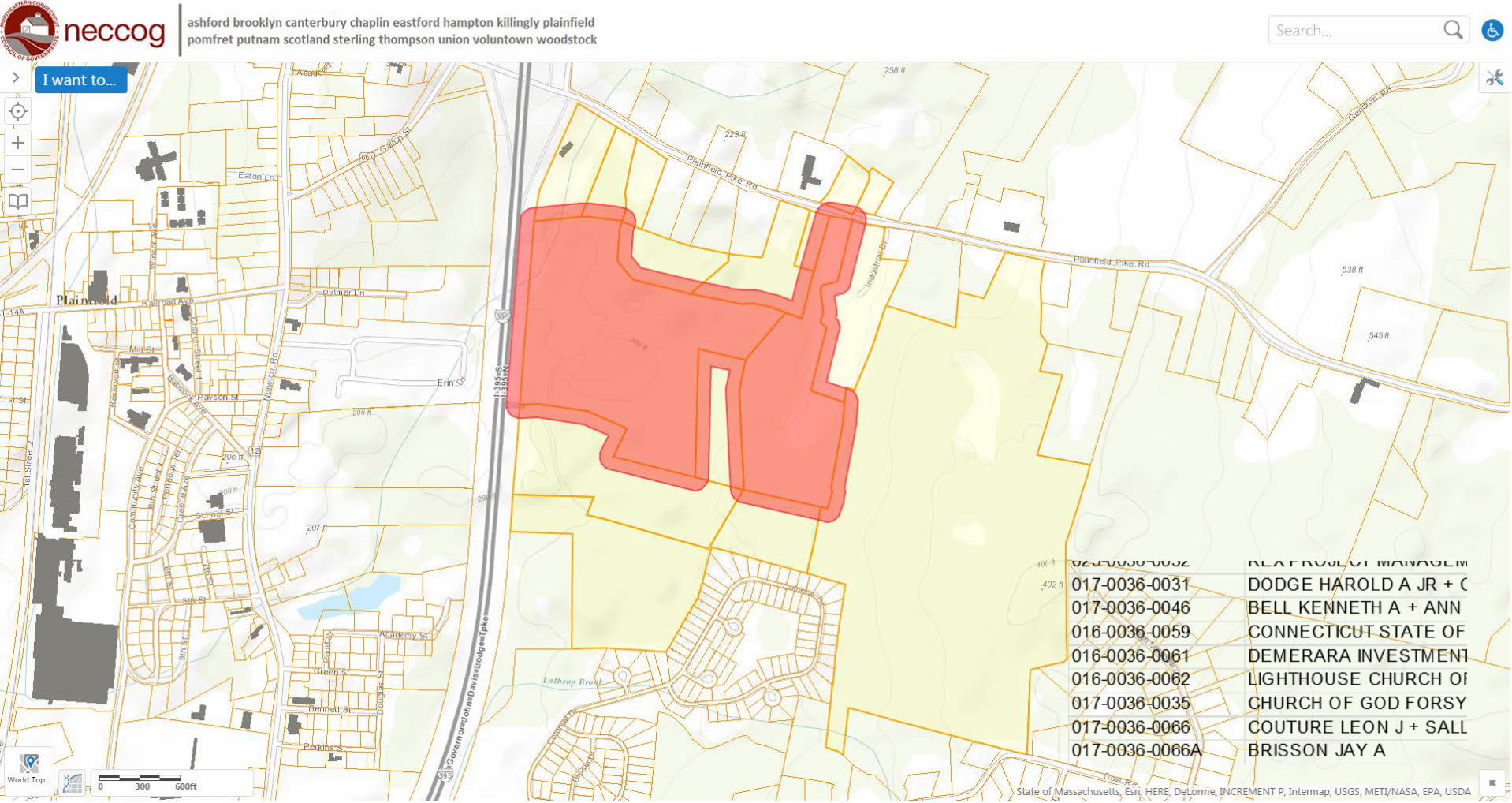
1. Windham Solar LLC (WS) included an abutters map under Exhibit D of its Petition(Petition) dated March 15, 2016 for the proposed project in Plainfield. Please submit aproperly-labeled abutters map identifying each parcel owner, including but not limited to, theabutters listed in Exhibit D of the petition.A revised Map has been attached identifying parcels, and the associated owners. – Exhibit A
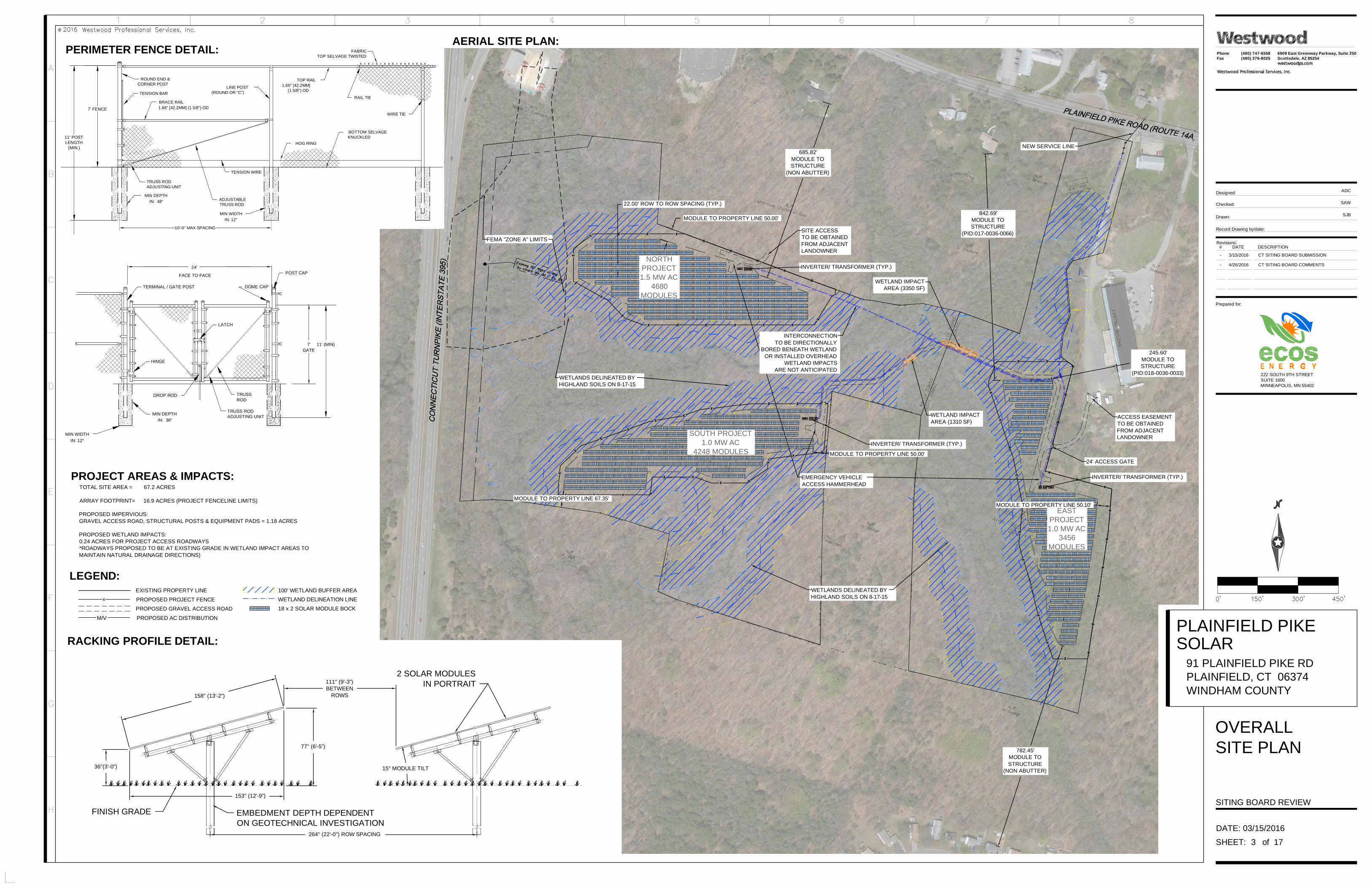
2. Where is the nearest off-site residence from the center of the eastern portion of the project?Provide the distance, direction, and address of such off-site residence. Where is the nearest-off-site residence from the center of the western portion of the project? Provide thedistance, direction, and address of such off-site residence.The overall site plan has been revised to show dimensions from the homes to the closestmodules to the facility and parcels are identified. – Exhibit B
Electrical/Energy Questions
3. The proposed project consists of two 1.0 megawatt (MW) and one 1.5 MW solar arraystotaling 3.5 MW. Is that 3.5 MW power output for the proposed solar project based onalternating current (AC)? If no, explain.Output to the grid is calculated in AC. The AC:DC ratio of the project is 1:1.17.
4. Indicate which solar arrays on the Overall Site Plan (Sheet 3 of 17) are the 1 MW arrays andwhich array is the 1.5 MW array.Boundaries have been added to the overall site plan, illustrating each array area. – Exhibit B
5. Page five of the Petition indicates that, “Each Facility will consist of approximately 3,395solar modules (based on a module rating of 345 watts).” How many “Facilities” is thePetitioner referring to? In other words, how many multiples of 3,395 solar modules areproposed? Please provide the number of solar modules for the two 1.0 MW and one 1.5MW arrays and for the entire proposed project.Boundaries have been added to the overall site plan illustrating each array area and totalmodule count. – Exhibit B

D:\Users\Steve Broyer\Box Sync\Projects - Solar\Eversource\1. Projects\Plainfield Pike\7. Permitting\Interrogatories Responses\PE1221 Interrogatories Set One.docx
6. Provide the total direct current (DC) power output in MW for the project based on the totalnumber of modules and wattage of such modules.The Maximum DC power output for each project on the site is based on the use of a 345wmodule throughout the site:North Project = 4680 Modules x 345W Module = 1,614,000 Watts DCEast Project = 3456 Modules x 345W Module = 1,192,320 Watts DCSouth Project = 4248 Modules x 345W Module = 1,465,560 Watts DC
Each project may be reduced in overall DC by using a lower wattage module, or removal ofmodules due to shading, or interconnection limitations.
7. In general, in the case of fixed solar panels, does orienting your solar panels to the southprovide a sort of balance (in terms of sun exposure) between the sun rising in the east andsetting in the west and ultimately result in optimizing (or attempting to maximize) your totalannual energy production (in kilowatt-hours) and your capacity factor?This statement is correct for the WS project. There are situations in some parts of thecountry where a more westerly orientation is preferred in order to maximize energyproduction during peak demand periods, but this is usually only considered in situationswhere the power purchaser pays a time-of-use rate that is higher during peak demandperiods than what is paid during shoulder or off-peak periods.
8. On page 7 of the Petition, WS notes that, according to the 2012 Integrated Resources Plan(IRP), the capacity factor for PV solar (and thus the proposed project) is approximately 13percent. Is that based on the DC or AC side of the proposed solar facility?The 13% capacity factor stated in the 2012 Integrated Resources Plan for Connecticut isbased on the DC nameplate of a solar facility.
9. How many 1,000-kilowatt inverters would be installed?(2) 1,000 kW inverters and (1) 1500 kW inverter is planned to be installed, however, WS mayelect to utilize a 60 kW string inverter design. In the case of a string inverter design,approximately 75 – 60 kW inverters would be installed throughout the projects.
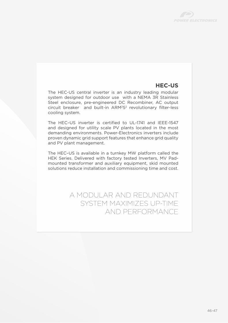
10. Provide the specifications sheet for the inverters.Attached are two specifications of the PV inverters that are currently being considered forthe project. - Exhibit C
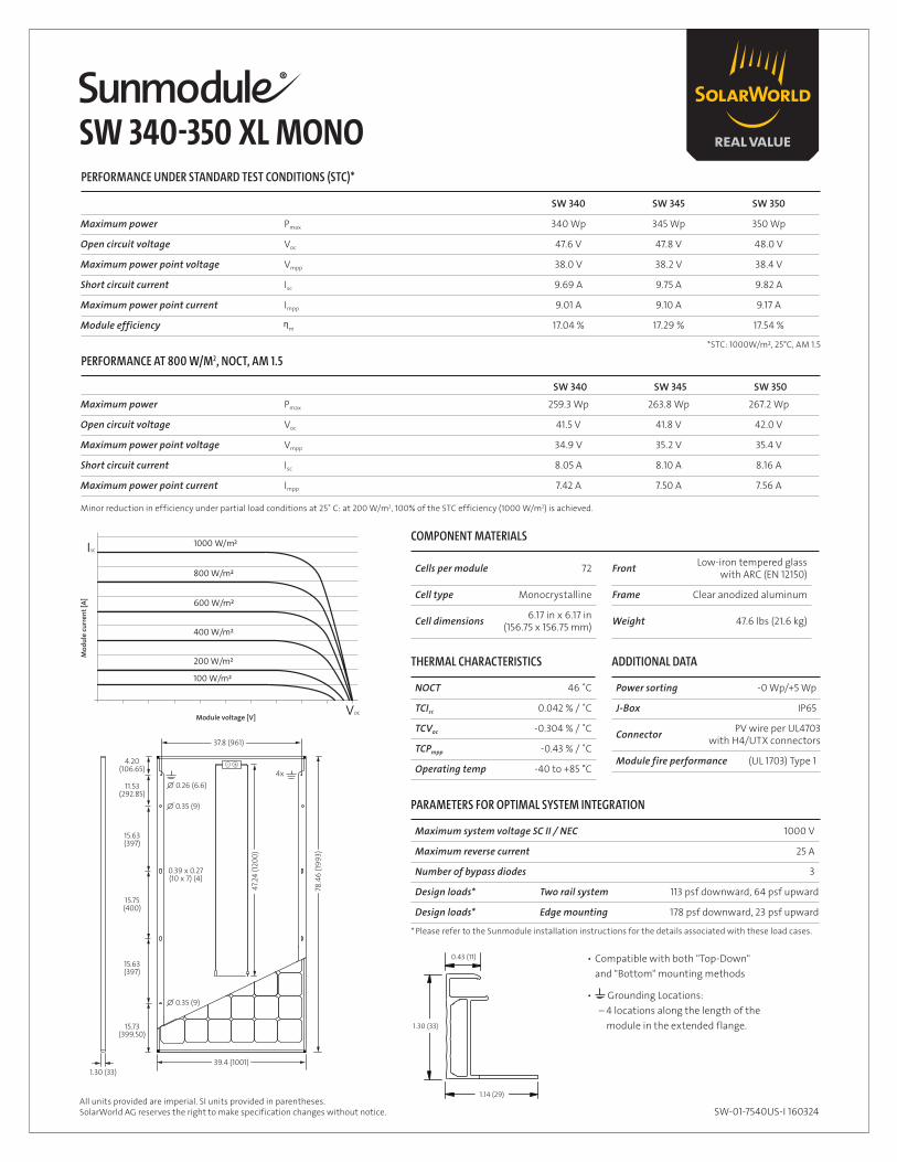
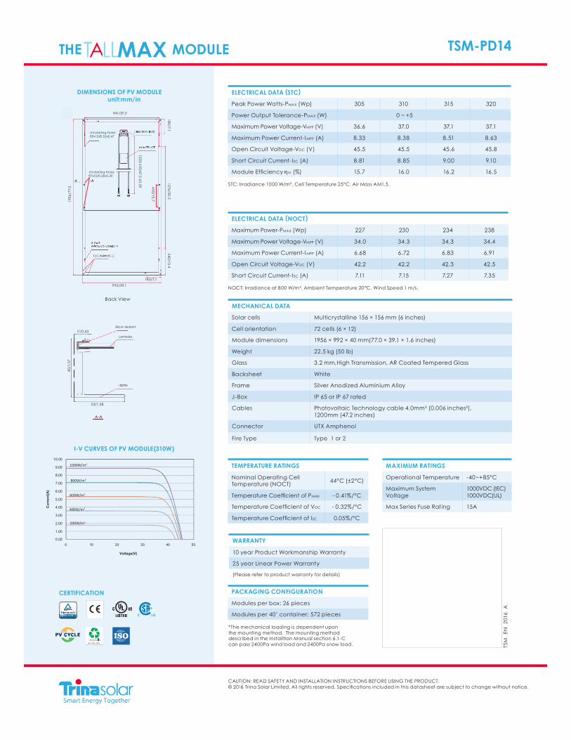
11. Provide the specification sheet for the proposed solar photovoltaic modules/panels.Attached are two specification of the PV modules that are currently being considered for theproject. – Exhibit D
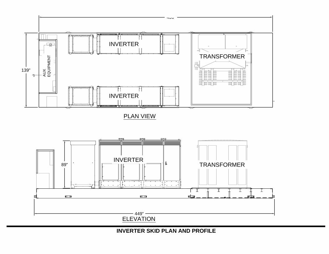
12. What are the estimated heights of the transformers and inverters?The transformer is approximately 7’ high. The 1,000 kW centralized inverter isapproximately 7’ high. The 60 kW string inverters would be mounted at a height ofapproximately 5’ – 6’ high and be located throughout the array field.A cut sheet of a typicalinverter/transformer pad has been added (2-1000-kilowatt inverters and 1 2000KvAtransformer) – Exhibit E

D:\Users\Steve Broyer\Box Sync\Projects - Solar\Eversource\1. Projects\Plainfield Pike\7. Permitting\Interrogatories Responses\PE1221 Interrogatories Set One.docx
13. Does Eversource currently have three-phase overhead electrical distribution on PlainfieldPike Road (Route 14A)?Yes.
Construction Questions
14. Would the tree clearing be performed in stages (e.g. five acres at a time), or would theclearing all be performed together as one stage of construction? (Note: ConnecticutDepartment of Energy and Environmental Protection “DEEP” General Permit for theDischarge of Stormwater and Dewatering Wastewasters Associated with ConstructionActivities states that, “Whenever possible, the site shall be phased to avoid the disturbanceof over five acres at a time…”)Tree clearing will be phased per the DEEP requirements, and the federal NPDESrequirements.
15. Estimate the amounts of cut and fill in cubic yards.500 yards cut and 500 yards fill, no export or import of soil is anticipated.
16. Approximately how tall would the poles be for the video cameras and meteorologicalequipment noted on page 12 of the Petition?Video and meteorological poles at the central skid will be 12’ to 15’ high. Approximately 6-10 perimeter fence posts per project limits will be installed at 12’ high and will have motiondetecting video mounted to atop the higher fence posts. These locations will be based onthe final footprint, and camera sight lines. The cameras are battery powered, and run on aninternal wireless project network.
17. How would the H-beams (that support the racking system) be driven into the ground?The intent is that a majority of the H-beams will be driven pile. However, an alternativegrouted foundation is also designed if subsurface boulders or ledge is encountered. Allstructural pile designs will be signed by a CT licensed Professional Engineer.
18. What are the estimated constructed hours (e.g. Monday through Friday 8 AM to 5 PM)?Local zoning code working hours will be adhered to which are as follows:
Plainfield Zoning Code Section 12.32.7.d.:Hours of operation. Operating hours shall be between the hours of 7:00 AM and 7:00 PM inall but the Industrial District. The Commission may stipulate reasonable operating hourswhich may be more or less restrictive depending upon the nature of surrounding land uses..
19. Approximately what size mesh does WS anticipate utilizing for the chain link fence? While2-inch mesh is a common size, would WS consider utilizing a mesh size less than two inchesas an anti-climbing measure? Would the fence have barbed wire?7’ chain link would be preferred. The sites security system will identify intruders or a breachin the perimeter on the site. WS would consider a smaller mesh, if costs are similar. Themajority of our sites do not have barb wire given our planned security measures, and barbwire is not intended for this project.

D:\Users\Steve Broyer\Box Sync\Projects - Solar\Eversource\1. Projects\Plainfield Pike\7. Permitting\Interrogatories Responses\PE1221 Interrogatories Set One.docx
20. Did WS consider an overhead electrical connection as a way to minimize disturbance in thevicinity of wetlands? Provide the pros and cons of overhead versus underground electricalconnections.An overhead alignment will be explored at the final design. If underground conduit isinstalled crossings of conveyances within the wetlands would be directionally bored, soexisting hydraulic flow lines remain undisturbed. Our experience has shown if conduit isopen trenched in areas that convey water, that it eventually erodes, and becomes a sitemaintenance and erosion issue.
Environmental Questions
21. Did the Petitioner attempt to minimize wetland crossings when designing the access drivesto each of the three solar arrays? For example, for the center (or southwestern) solar array,could the access to that solar array be shifted to the northwest to reduce the 1,455 squarefeet of wetland impacts? (See Overall Site Plan – Sheet 3 of 17).The site visit, and updated wetland report, identifies a brook on the site that has constantflow, the crossing location has been abandoned and WS is exploring other options foraccessing the central area of the site. Also the alignment of the access roads have beenrevised given the site visit to more upland locations and the overall project wetland impacthas been reduced to 4660 sf. - Exhibit B
22. Has the Petitioner received a response from the Connecticut Department of Energy andEnvironmental Protection regarding the Natural Diversity Database to date? If yes, providea copy of such correspondence. While DEEP reviews state-listed species, are any federally-listed species known in the vicinity of the proposed project? If yes, describe possibleimpacts to such species and mitigation measures.WS is still awaiting a response from DEEP on the project, our submission was made inNovember of 2105.
A search of the Federal Endangered Species highlights the following Species Occurrence onthe project:
AnimalsNorthern long-eared Bat (Myotis septentrionalis)Piping Plover (Charadrius melodus)
PlantsSandplain gerardia (Agalinis acuta)Small Whorled pogonia (Isotria medeoloides)
A wildlife biologist will be contacted to perform a site visit and determine if the sitepossesses the appropriate habitat for the above plants and animals. The biologist willdetermine if mitigation measures are necessary, and to what extent.

D:\Users\Steve Broyer\Box Sync\Projects - Solar\Eversource\1. Projects\Plainfield Pike\7. Permitting\Interrogatories Responses\PE1221 Interrogatories Set One.docx
23. Is the total tree clearing area for the proposed project about 18.4 acres? If no, provide thetotal tree clearing area. Does this total also include the tree removal in wetland areas?Approximately how many acres of tree clearing in wetland areas are expected?
The revised site plan has the following values:Total site clearing = 18.07 ACClearing in wetland = 0.10 ACClearing in wetland buffers = 3.6 AC
24. Provide the carbon debt payback period. Specifically, as an estimate, you may utilize theU.S. Environmental Protection Agency (EPA) number of 1.22 metric tons of carbon dioxidesequestered by one acre of average U.S. forest in one year. That number can be multipliedby the number of acres of trees to be cleared to estimate the annual loss of carbon dioxidesequestration in metric tons per year for the project. Then the total projected annualelectrical production in kilowatt-hours for the solar facility can be multiplied by the EPAestimate of 6.89551 x 10⁻⁴ metric tons of carbon dioxide displaced per kilowatt-hour in orderto provide the annual carbon dioxide emissions avoided by the operation of solar plant.Based on this or a different analysis, compute the number of months or years it would taketo “break even” with carbon dioxide or when the carbon dioxide emissions reductionswould equal the sequestration loss. (Data source: http://www.epa.gov/energy/ghg-equivalencies-calculator-calculations-and-references)WS is proposing to clear 18.1 acres as part of the construction of the facility. Based on theformula provided above, the loss of carbon dioxide sequestration would be 22.082 tons peryear. The WS facility is expected to generate 5,434,065 kWh during its first year of operation,degrading by 0.5% per year thereafter. Based on the EPA estimates provided above, the WSfacility would off-set 3,747 metric tons of carbon dioxide during its first year of operation orapproximately 10.27 tons per day. Therefore, the sequestration loss from clearing the treeswould be off-set by the solar facility in 2.15 days of operation in the first year.
25. On page 11 of the Petition, WS estimates 115,000 tons of CO2 equivalent offset oreliminated during the 45-year life of the facility. How was the 115,000 tons computed?The carbon off-set estimates provided in the Petition for Declaratory Ruling were based offof an estimated carbon off-set rate of 1.645 lbs per kWh of generation. This figure was basedon a generation mix of 50% coal (2.07 lbs per kWh) and 50% natural gas (1.22 lbs per kWh)(source: https://www.eia.gov/tools/faqs/faq.cfm?id=74&t=11). Windham Solar is willingto accept the calculations provided by the EPA above.
26. Has the Petitioner received a response from the State Historic Preservation Office to date?If yes, provide a copy of such correspondence.An application was submitted to SHPO by WS in mid-February. WS is still awaiting aresponse from SHPO on the parcel.
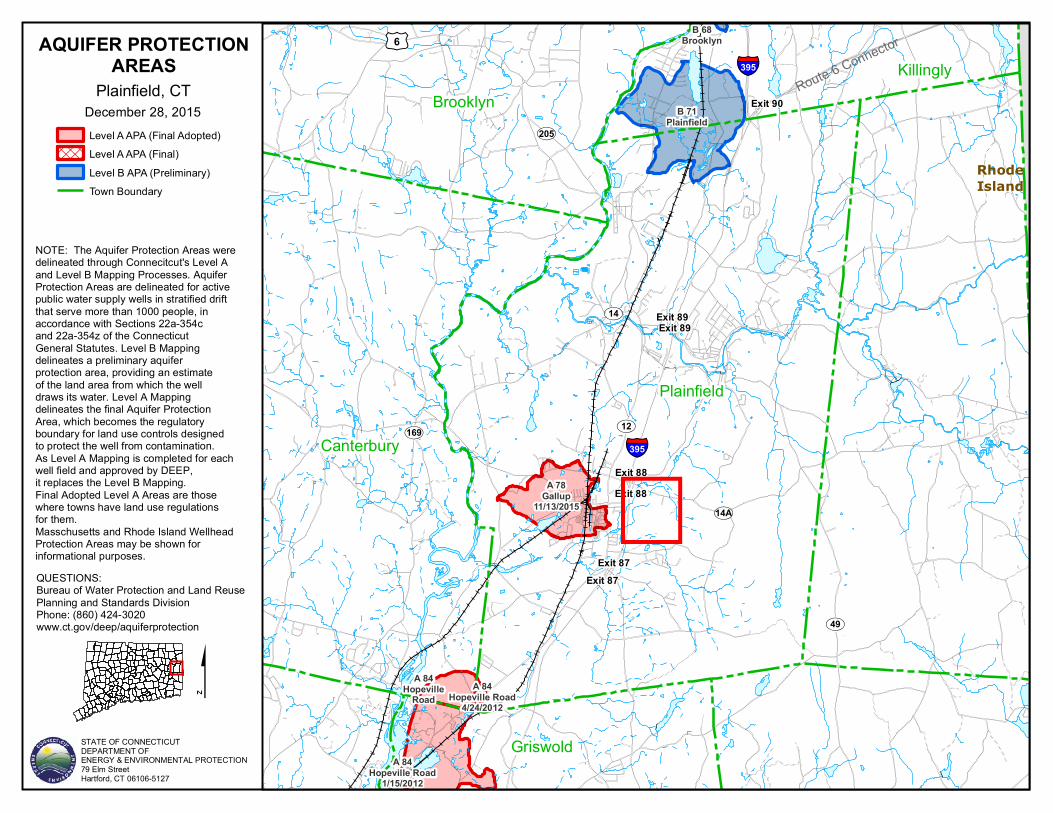
27. Is the proposed project located within an aquifer protection area?No, an acquifer protection map has been attached. - Exhibit F

D:\Users\Steve Broyer\Box Sync\Projects - Solar\Eversource\1. Projects\Plainfield Pike\7. Permitting\Interrogatories Responses\PE1221 Interrogatories Set One.docx
28. Is any of the proposed project located within a 100-year or 500-year flood zone? If yes,indicate which portion(s) of the project area are located within flood zones, and provide aFederal Emergency Management Agency flood zone map that includes the subject property.Yes, a portion of the western site is Zone A, no modules are proposed in the area, and themapping is not following existing topography. An Elevation of the Zone will be requestedfrom FEMA to determine the flood elevation in the aera. A freeboard separation of 1 footfrom that elevation will be incorporated to the design of all electrical generating equipment.
29. In Exhibit H of the Petition, it is stated that a stormwater pond would be necessary tocontrol stormwater runoff. On the Overall Site Plan, indicate the location of the stormwaterpond. Would construction of the stormwater pond be within wetlands? Is so, identify thesquare feet of disturbance and permits necessary for this action.Ponding will be installed at a continuous elevation at the perimeter of the site footprint, andsized upon the contributing drainage area, construction will not occur within the wetlands,but potentially within the wetland buffer. Post construction hydraulic discharge from thesite, will be less than pre construction values. Detailed hydrology, and grading design, will bean element of the project construction documents.
30. In Exhibit F of the Petition, by letter dated February 2, 2016, Highland Soils, LLC indicatedthat a more detailed wetland report would be prepared following another site visit. Does thePetitioner have an updated Wetlands Report at this time? If yes, provide a copy of such fullreport. Were any vernal pools located as a result of such site visit? Are any additionalwetland and/or vernal pool protective measures proposed at this time? If no visit has beenmade, provide an estimated timeframe for the visit and updated report.Updated Wetland report with vernal pool analysis is attached –Exhibit G.
31. If vernal pools are identified as result of a site visit, include the following. Describe themethodologies used to evaluate the vernal pools and include the date(s) of hisstudies. Specifically detail how the egg masses were counted, how many visits over whatperiod of time were made, and indicate if any other techniques such as minnow trappingwere used, if applicable.Updated Wetland report with vernal pool analysis is attached –Exhibit G.
32. If vernal pools are identified as a result of a site visit, include the following. Analyze thevernal pools using the Calhoun and Klemens methodology. While forested habitat ispreferable, open habitat may be used and also can serve as areas that animals movethrough. Open habitat also over time can improve by regrowth. It cannot be merelydiscounted as developed habitat as one can have areas that have houses and roads. Anexcellent example of how to correctly analyze a habitat that has various components is thatfor Council Docket 455 (Tab 14 of that application) which clearly shows the correcttreatment of wooded, open and grassed areas, versus developed areas. Only the developedareas are considered to be lost habitat. This document, as a sample wetlands and vernalpool analysis, has been attached for your convenience. The map at the end of the documentis a useful template or reference.Updated Wetland report with vernal pool analysis is attached –Exhibit G.

D:\Users\Steve Broyer\Box Sync\Projects - Solar\Eversource\1. Projects\Plainfield Pike\7. Permitting\Interrogatories Responses\PE1221 Interrogatories Set One.docx
33. Would WS comply with the recommendations on page 22 of the Phase I Environmental SiteAssessment?WS doesn’t intend on any additional investigation given the location of the foundation andthat there is no proposed disturbance in the area.
34. Would the solar panels “heat” rainwater and potentially thermally pollute wetlands?No. There is no evidence that this occurs given the short duration that rainwater is on thepanels, furthermore, the panels would be clouded during the time of rainfall, so surfacetemperatures of the panels would be less than on a sunny day.
35. Would the proposed project meet the applicable DEEP noise standards at the boundaries ofthe subject properties? (Sources of noise might include but not be limited to inverters,transformers, etc.)Yes.
Maintenance Questions
36. How would WS handle potential snow accumulation on the panels and its effects ofblocking the sunlight?Snow soiling has been accounted for in our solar modeling, no cleaning of panels iscontemplated.
37. Has WS done any analysis to determine structural limits of snow accumulation on the solarpanels and steel support structures, assuming heavy, wet snow? What accumulation of snowcould the structures handle? Would WS clear snow from the panels when it approached thelimit?The project racking will be designed for the regions wind and snow loading, and will bestamped by a licensed structural engineer. No clearing of snow is contemplated.
38. Would any mowing be required under or around the proposed solar panels/modules, and ifso, approximately how often would mowing occur?
Below is a typical operations and maintenance schedule, an operations and maintenancemanual will be included in the projects final design.
Monthly:Inspect the site vegetation growth, and establish a mowing schedule keeping vegetationbetween 6” and 18”. Any growth above 18” begins shading lower elevation panels.Inspect the gravel roadways for washout locations or potential erosion issues, schedulemaintenance as necessaryInspect the array field for any locations where excessive growth is identified, schedulemaintenance as necessary
Bi-Annually (April and October):Inspect vegetation during both the growing and non-growing seasons to ensure propergroundcover density.

D:\Users\Steve Broyer\Box Sync\Projects - Solar\Eversource\1. Projects\Plainfield Pike\7. Permitting\Interrogatories Responses\PE1221 Interrogatories Set One.docx
Identify stumps and areas within the array or at the perimeter, that have grown to createshading, schedule maintenance as necessary.Replant bare areas or areas with sparse growth with the project specific seed mix.Inspect perimeter landscaping screening, to ensure ongoing establishment of new plantings.
Blake Nicholson
Typewritten Text
016-0036-0059
Blake Nicholson
Typewritten Text
016-0036-061
Blake Nicholson
Typewritten Text
016-0036-0062
Blake Nicholson
Typewritten Text
Blake Nicholson
Typewritten Text
Blake Nicholson
Typewritten Text
Subject Property
Blake Nicholson
Typewritten Text
017-0036-0035
Blake Nicholson
Typewritten Text
Blake Nicholson
Typewritten Text
017-0036-0066
Blake Nicholson
Typewritten Text
016-0057-0003
Blake Nicholson
Typewritten Text
Blake Nicholson
Typewritten Text
016-0057-0004
Blake Nicholson
Typewritten Text
Blake Nicholson
Typewritten Text
017-0036-0033
Blake Nicholson
Typewritten Text
025-0036-0032
Blake Nicholson
Typewritten Text
017-0036-0031
Blake Nicholson
Typewritten Text
Blake Nicholson
Typewritten Text
017-0036-0031
Blake Nicholson
Typewritten Text
017-0036-0046
Blake Nicholson
Typewritten Text
Blake Nicholson
Text Box
Blake Nicholson
Placed Image
M/V
M/V
M/V
M/V
M/V
M/V
M/V
M/V
M/V
M/V
M/V
M/V
M/V
M/V
M/V
M/V
M/V
M/V
M/V
M/V
M/V
M/V
M/V
M/V
M/V
M/V
M/V
M/V
M/V
M/V
M/V
M/V
M/V
M/V
M/VM/V M/V
NORTHPROJECT1.5 MW AC
4680MODULES
M/VM/VM/V
M/V
M/V
M/V
M/V
M/V
M/V
M/V
M/V
M/VM/VM/V
M/V
M/V
SOUTH PROJECT1.0 MW AC
4248 MODULES
EASTPROJECT1.0 MW AC
3456MODULES
24' ACCESS GATE
NEW SERVICE LINE
INVERTER/ TRANSFORMER (TYP.)
INVERTER/ TRANSFORMER (TYP.)
INVERTER/ TRANSFORMER (TYP.)
WETLANDS DELINEATED BYHIGHLAND SOILS ON 8-17-15
WETLANDS DELINEATED BYHIGHLAND SOILS ON 8-17-15
EMERGENCY VEHICLEACCESS HAMMERHEAD
22.00' ROW TO ROW SPACING (TYP.)
MODULE TO PROPERTY LINE 50.00'
MODULE TO PROPERTY LINE 67.35'
MODULE TO PROPERTY LINE 50.00'
MODULE TO PROPERTY LINE 50.10'
WETLAND IMPACTAREA (3350 SF)
WETLAND IMPACTAREA (1310 SF)
ACCESS EASEMENTTO BE OBTAINEDFROM ADJACENTLANDOWNER
SITE ACCESSTO BE OBTAINEDFROM ADJACENTLANDOWNER
245.60'MODULE TOSTRUCTURE
(PID:018-0036-0033)
842.69'MODULE TOSTRUCTURE
(PID:017-0036-0066)
685.82'MODULE TOSTRUCTURE
(NON ABUTTER)
FEMA "ZONE A" LIMITS
782.45'MODULE TOSTRUCTURE
(NON ABUTTER)
INTERCONNECTIONTO BE DIRECTIONALLY
BORED BENEATH WETLANDOR INSTALLED OVERHEAD
WETLAND IMPACTSARE NOT ANTICIPATED
36"(3'-0")
158" (13'-2")
77" (6'-5")
15° MODULE TILT
2 SOLAR MODULESIN PORTRAIT
FINISH GRADE EMBEDMENT DEPTH DEPENDENTON GEOTECHNICAL INVESTIGATION
153" (12'-9")
111" (9'-3")BETWEEN
ROWS
264" (22'-0") ROW SPACING
Record Drawing by/date:
Drawn:
Checked:
Designed:
Prepared for:
ADC
SAW
SJB
Revisions:# DATE DESCRIPTION
- 3/15/2016 CT SITING BOARD SUBMISSION
SITING BOARD REVIEW
222 SOUTH 9TH STREETSUITE 1600MINNEAPOLIS, MN 55402
SHEET: of 17DATE: 03/15/2016
PLAINFIELD PIKE
PLAINFIELD, CT 0637491 PLAINFIELD PIKE RD
WINDHAM COUNTY
SOLAR
Phone (480) 747-6558 6909 East Greenway Parkway, Suite 250Fax (480) 376-8025 Scottsdale, AZ 85254
- 4/26/2016 CT SITING BOARD COMMENTS
OVERALLSITE PLAN
3
RACKING PROFILE DETAIL:
AERIAL SITE PLAN:
IN: 36"MIN DEPTH TRUSS ROD
ADJUSTING UNIT
TERMINAL / GATE POST DOME CAP
POST CAP
HINGE
LATCH
TRUSSROD
DROP ROD
MIN WIDTHIN: 12"
7'
24'
FACE TO FACE
11' (MIN)
PERIMETER FENCE DETAIL:
ADJUSTABLETRUSS ROD
BOTTOM SELVAGE
RAIL TIE
KNUCKLEDHOG RING
FABRICTOP SELVAGE TWISTED
MIN DEPTHIN: 48"
TOP RAIL
(1 5/8") OD1.66" [42.2MM]
(ROUND OR "C")LINE POST
CORNER POSTROUND END &
10'-0" MAX SPACING
1.66" [42.2MM] (1 5/8") ODBRACE RAIL
TENSION WIRE
TRUSS RODADJUSTING UNIT
WIRE TIE
TENSION BAR
MIN WIDTHIN: 12"
7' FENCE
11' POSTLENGTH
(MIN.)
LEGEND:
PROPOSED PROJECT FENCEPROPOSED GRAVEL ACCESS ROAD
EXISTING PROPERTY LINE
PROPOSED AC DISTRIBUTIONM/V
100' WETLAND BUFFER AREAWETLAND DELINEATION LINE18 x 2 SOLAR MODULE BOCK
GATE
TOTAL SITE AREA = 67.2 ACRES
ARRAY FOOTPRINT= 16.9 ACRES (PROJECT FENCELINE LIMITS)
PROPOSED IMPERVIOUS:GRAVEL ACCESS ROAD, STRUCTURAL POSTS & EQUIPMENT PADS = 1.18 ACRES
PROPOSED WETLAND IMPACTS:0.24 ACRES FOR PROJECT ACCESS ROADWAYS*ROADWAYS PROPOSED TO BE AT EXISTING GRADE IN WETLAND IMPACT AREAS TOMAINTAIN NATURAL DRAINAGE DIRECTIONS)
PROJECT AREAS & IMPACTS:

POWER ELECTRONICS / SOLAR INVERTER
NORTH AMERICAOUTDOOR UTILITY SCALESolar Inverters

44-45

POWER ELECTRONICS / SOLAR INVERTER
HEC-USUTILITY SCALE SOLAR INVERTER
EXTENDED MPPT
The HEC-US central inverter is an industry leading modular system designed for outdoor use with a NEMA 3R Stainless Steel enclosure, pre-engineered DC Recombiner, AC output circuit breaker and built-in ARM2S2 revolutionary filter-less cooling system.
The HEC–US inverter is certified to UL-1741 and IEEE-1547 and designed for utility scale PV plants located in the most demanding environments. Power-Electronics inverters include proven dynamic grid support features that enhance grid quality and PV plant management.
The HEC–US is available in a turnkey MW platform called the HEK Series. Delivered with factory tested Inverters, MV Pad-mounted transformer and auxiliary equipment, skid mounted solutions reduce installation and commissioning time and cost.
A MODULAR AND REDUNDANT SYSTEM MAXIMIZES UP-TIME
AND PERFORMANCE
HEC-US
46-47
POWER ELECTRONICS / SOLAR INVERTER
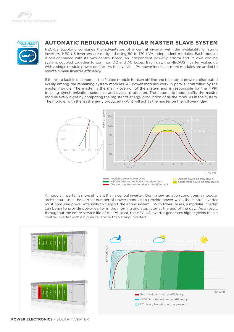
HEC-US topology combines the advantages of a central inverter with the availability of string inverters. HEC-US inverters are designed using 80 to 170 KVA independent modules. Each module is self-contained with its own control board, an independent power platform and its own cooling system, coupled together to common DC and AC buses. Each day, the HEC-US inverter wakes up with a single module power on-line. As the available PV power increases more modules are added to maintain peak inverter efficiency.
If there is a fault in one module, the faulted module is taken off-line and the output power is distributed evenly among the remaining system modules. All power modules work in parallel controlled by the master module. The master is the main governor of the system and is responsible for the MPPt tracking, synchronization sequence and overall protection. The automatic mode shifts the master module every night by comparing the register of energy production of all the modules in the system. The module with the least energy produced (kWh) will act as the master on the following day.
AUTOMATIC REDUNDANT MODULAR MASTER SLAVE SYSTEM
0 3 5 7 9 11 13 15 17 19 21
1200
900
600
300
1500
AUGUST
SEPTEMBER
PO
WE
R (
KW
)
TIME (h)
Available solar Power (kW)HEC-US Production (kW) -1 Module faultCompetitors Production (kW) -1 Module fault
4:25
10kW
4:354:30
5kW
15kW
4:20 4:40
August saved Energy (kWh)September saved Energy (kWh)
A modular inverter is more efficient than a central inverter. During low radiation conditions, a modular architecture uses the correct number of power modules to provide power while the central inverter must consume power internally to support the entire system. With lower losses, a modular inverter can begin to provide power earlier in the morning and stop later at the end of the day. As a result, throughout the entire service life of the PV plant, the HEC-US inverter generates higher yields than a central inverter with a higher reliability than string inverters.
EF
FIC
IEN
CY
HEC-US
POWER

50-51
The design philosophy for the HEC-US inverters is to oversize sensitive components (like IGBTs & DC bus capacitors) and provide sufficient margin so the HEC-US can operate at 122F (50°C) with no power derating. Power-Electronics equipment is installed in mines, water treatment plants and concentrated solar power facilities in the most demanding locations in the world. Our expertise in harsh environments is the foundation for the perfect technical solution for our outdoor solar inverters.
The cooling systems on the HEC-US modules are divided into two main areas: the clean area (electronics) and the hot area (LC filters and heat sinks). The electronics are sealed in a NEMA 4 area and use a temperature control low flow cooling system that reduces filter maintenance. The hot area integrates independent speed controlled fans per each module that reduce stand-by consumption at low capacity, minimize audible noise and increase cooling capacity for PV installations located in hot environments or high altitudes.
REVOLUTIONARY COOLING SYSTEM
ELECTRONICS
FILTERS ANDHEAT SINKS
AVAILABLE WITH FRONT OR BACK EXHAUST AIR VENTS FOR FLEXIBILITY IN SKID INTEGRATION
HE
C-U
S
POWER ELECTRONICS / SOLAR INVERTER
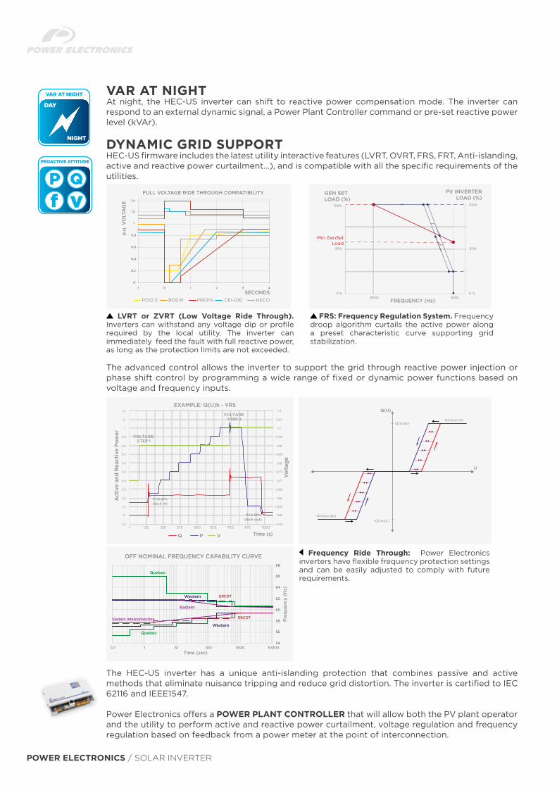
At night, the HEC-US inverter can shift to reactive power compensation mode. The inverter can respond to an external dynamic signal, a Power Plant Controller command or pre-set reactive power level (kVAr).
VAR AT NIGHT
HEC-US firmware includes the latest utility interactive features (LVRT, OVRT, FRS, FRT, Anti-islanding, active and reactive power curtailment…), and is compatible with all the specific requirements of the utilities.
The advanced control allows the inverter to support the grid through reactive power injection or phase shift control by programming a wide range of fixed or dynamic power functions based on voltage and frequency inputs.
FRS: Frequency Regulation System. Frequency droop algorithm curtails the active power along a preset characteristic curve supporting grid stabilization.
Frequency Ride Through: Power Electronics inverters have flexible frequency protection settings and can be easily adjusted to comply with future requirements.
The HEC-US inverter has a unique anti-islanding protection that combines passive and active methods that eliminate nuisance tripping and reduce grid distortion. The inverter is certified to IEC 62116 and IEEE1547.
Power Electronics offers a POWER PLANT CONTROLLER that will allow both the PV plant operator and the utility to perform active and reactive power curtailment, voltage regulation and frequency regulation based on feedback from a power meter at the point of interconnection.
DYNAMIC GRID SUPPORT
1.2
1.4
1
0.8
0.6
0.4
0.2
0
-1 0 1 2 3 4
BDEWPO12.3 CEI-016PREPA HECO
FULL VOLTAGE RIDE THROUGH COMPATIBILITY
SECONDS
p.u.
VO
LTA
GE
PV INVERTERLOAD (%)
GEN SET LOAD (%)
FREQUENCY (Hz)50Hz
0 %
50%
100%
0 %
50%
100%
52Hz
Min GenSetLoad
Q(U)
U
Q(max)
-Q(max)Qmax(cap)
Qmax(ind)
Q P V
EXAMPLE: Q(U)h - VRS1.2
1.1
1
0.9
0.8
0.7
0.6
0.5
0.4
0.3
0.2
0.1
0
1 125 250 375 500 625 750 875 1000-0.1
1.11
1.1
1.105
1.095
1.09
1.085
1.08
1.075
1.07
1.065
1.06
1.055
1.05
1.045
Time (s)
Act
ive
and
Rea
ctiv
e Po
wer
Vol
tage
VOLTAGE STEP 1
VOLTAGE STEP 2
P>0.2Pn(lock in)
P>0.5Pn(lock out)
LVRT or ZVRT (Low Voltage Ride Through). Inverters can withstand any voltage dip or profile required by the local utility. The inverter can immediately feed the fault with full reactive power, as long as the protection limits are not exceeded.
68
66
64
62
60
58
56
541000010001001010.1
OFF NOMINAL FREQUENCY CAPABILITY CURVE
Freq
uenc
y (H
z)
Time (sec)
Quebec
Quebec
Western
Western
Eastern
ERCOT
ERCOTEastern Interconnection
52-53
HEC-US HEC-US+ NEC2011 HEC-US+ NEC2014
+
-
DC
BUSAC
CONTACTOR
T(ºC)
A20
8-39
0V A
C B
US
UP
TO
10
MODULES
CA
NC
OM
MU
NIC
ATI
ON
SY
NC
HR
ON
IZA
TIO
NMODULE 1
MODULE 10
DC
BUSAC
CONTACTOR
T(ºC)
A A
A
ETH
ER
NE
TC
OM
MU
NIC
ATI
ON
ETHEWIFI
RNET
SWITCH
O
RS485
NEC 2014FSDK SUBSYSTEM HEC-US
HEC-US+
VERVOLTAGE
PROTECT ON
RS485
A
A
A
A
+
-
CONTROL
CONTROL
METEO - STATIONPOWER PLANT CONTROLLER
Communication Ports: RS485, RS232, USB
Analogue and Digital E/S
GROUND FAULT PROTECTION
MO
DU
LAR
MP
Pt D
C B
US
UP
TO 5
MP
Pt
DCCONTACTOR
INVERTERBRIDGE
SINUSOIDALFILTER
AUTOMATICCIRCUIT
BREAKER
FUSES
CIRCUIT BREAKER
R
S
T
208V
AC
PO
WER
SOU
RC
E 2k
VA
PE
OVERVOLTAGEPROTECTION
L1
L2
L3 208
– 39
0VA
CO
UTP
UT
POW
ER
OVERVOLTAGEPROTECTION
AUXILIARTRANSFORMER
EM
C F
ILTE
R
Aux
iliar
y Po
wer
SU
pply
400
VAC
DCCONTACTOR
FUSES INVERTERBRIDGE
SINUSOIDALFILTER
AUTOMATICCIRCUIT
BREAKER
EM
RET
LIF
C
R
S
TPE
208V
AC
EX
TER
NA
LPO
WER
SU
PPLY
EM
CFI
LTE
RE
MC
FILT
ER
208-330-360-390 / 400
(OPT
ION
AL)
FUSEPROTECTION
EM
CFI
LTE
R
CONTACTORSFUSES
CT´s FORZONE MONITORING
FUSES
+
-
FUSEPROTECTION
192.9”
94
.5”
192.9”
94
.5”
153.5”
94
.5”
232.3”
94
.5”
232.3”
94
.5”
285”
94
.5”
248”
RECOMBINER
89.4
”50
” 94
.5”
208.7”
RECOMBINER
89.4
”50
” 94
.5”
287.4”
89.4
”
RECOMBINER
50” 94
.5”
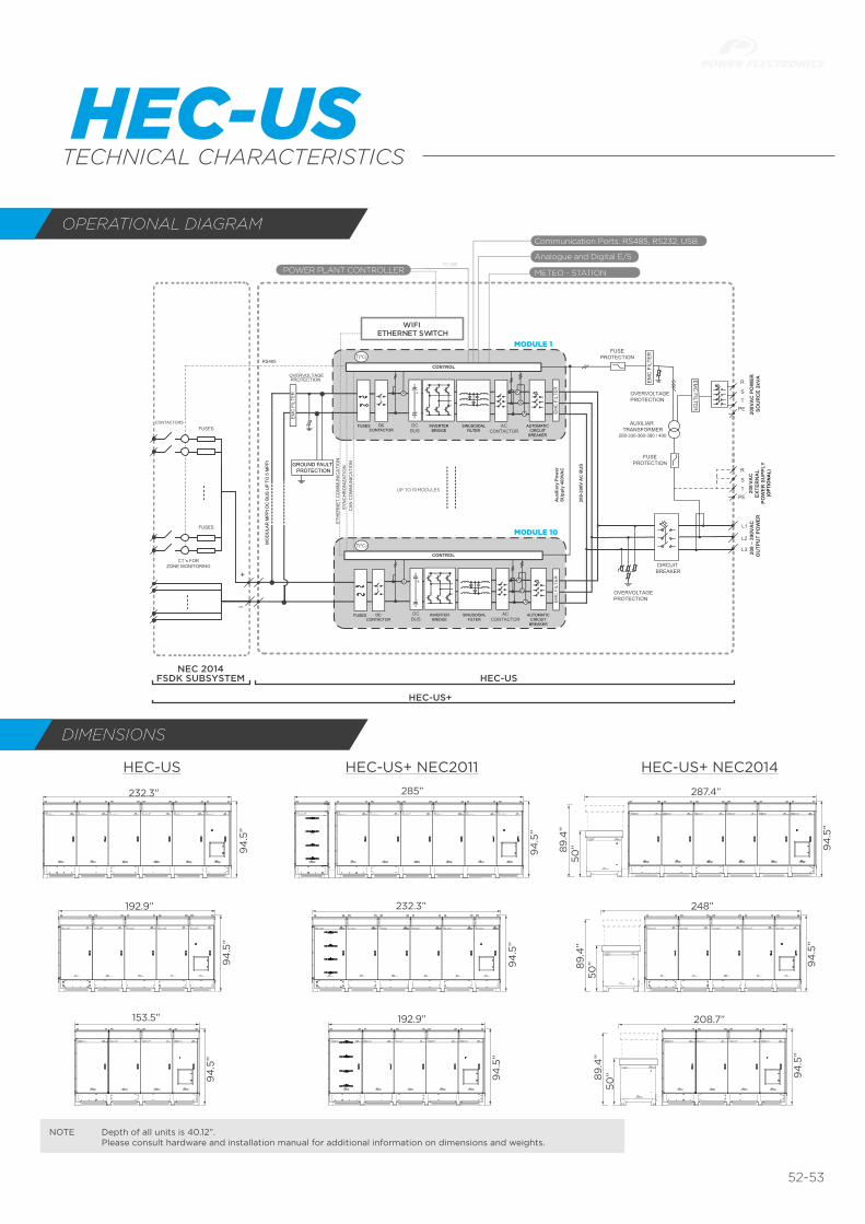
OPERATIONAL DIAGRAM
DIMENSIONS
NOTE Depth of all units is 40.12”. Please consult hardware and installation manual for additional information on dimensions and weights.
HEC-USTECHNICAL CHARACTERISTICS
POWER ELECTRONICS / SOLAR INVERTER
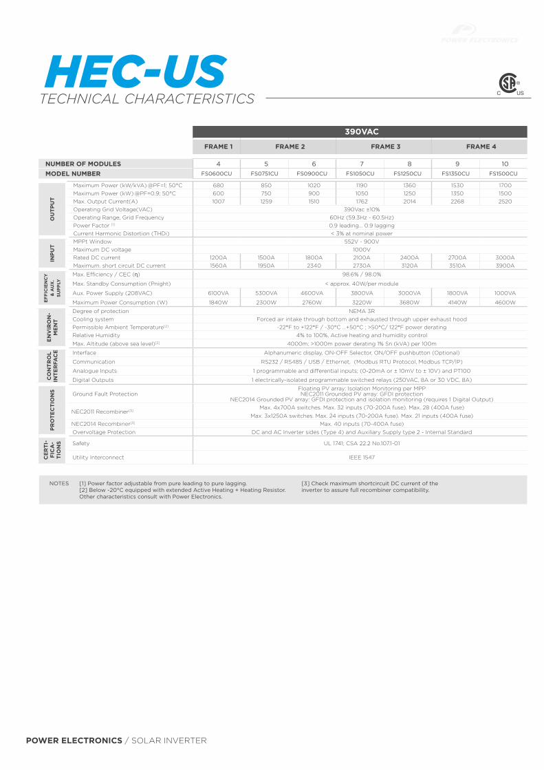
390VAC
FRAME 1 FRAME 2 FRAME 3 FRAME 4
NUMBER OF MODULES 4 5 6 7 8 9 10MODEL NUMBER FS0600CU FS0751CU FS0900CU FS1050CU FS1250CU FS1350CU FS1500CU
[1] Power factor adjustable from pure leading to pure lagging. [2] Below -20°C equipped with extended Active Heating + Heating Resistor.Other characteristics consult with Power Electronics.
NOTES [3] Check maximum shortcircuit DC current of the inverter to assure full recombiner compatibility.
OU
TPU
T
Maximum Power (kW/kVA) @PF=1; 50°C 680 850 1020 1190 1360 1530 1700Maximum Power (kW) @PF=0.9; 50°C 600 750 900 1050 1250 1350 1500Max. Output Current(A) 1007 1259 1510 1762 2014 2268 2520Operating Grid Voltage(VAC) 390Vac ±10%Operating Range, Grid Frequency 60Hz (59.3Hz - 60.5Hz)Power Factor [1] 0.9 leading... 0.9 laggingCurrent Harmonic Distortion (THDi) < 3% at nominal power
INP
UT
MPPt Window 552V - 900VMaximum DC voltage 1000VRated DC current 1200A 1500A 1800A 2100A 2400A 2700A 3000AMaximum. short circuit DC current 1560A 1950A 2340 2730A 3120A 3510A 3900A
EFF
ICIE
NC
Y
& A
UX
. SU
PP
LY
Max. Efficiency / CEC (η) 98.6% / 98.0%
Max. Standby Consumption (Pnight) < approx. 40W/per module
Aux. Power Supply (208VAC) 6100VA 5300VA 4600VA 3800VA 3000VA 1800VA 1000VA
Maximum Power Consumption (W) 1840W 2300W 2760W 3220W 3680W 4140W 4600W
EN
VIR
ON
-M
EN
T
Degree of protection NEMA 3RCooling system Forced air intake through bottom and exhausted through upper exhaust hoodPermissible Ambient Temperature[2] -22°F to +122°F / -30°C …+50°C ; >50°C/ 122°F power deratingRelative Humidity 4% to 100%, Active heating and humidity control
Max. Altitude (above sea level)[2] 4000m; >1000m power derating 1% Sn (kVA) per 100m
CO
NTR
OL
INTE
RFA
CE Interface Alphanumeric display, ON-OFF Selector, ON/OFF pushbutton (Optional)
Communication RS232 / RS485 / USB / Ethernet, (Modbus RTU Protocol, Modbus TCP/IP)
Analogue Inputs 1 programmable and differential inputs; (0-20mA or ± 10mV to ± 10V) and PT100
Digital Outputs 1 electrically-isolated programmable switched relays (250VAC, 8A or 30 VDC, 8A)
PR
OTE
CTI
ON
S Ground Fault ProtectionFloating PV array: Isolation Monitoring per MPPNEC2011 Grounded PV array: GFDI protection
NEC2014 Grounded PV array: GFDI protection and isolation monitoring (requires 1 Digital Output)
NEC2011 Recombiner[3]Max. 4x700A switches. Max. 32 inputs (70-200A fuse). Max. 28 (400A fuse)
Max. 3x1250A switches. Max. 24 inputs (70-200A fuse). Max. 21 inputs (400A fuse)NEC2014 Recombiner[3] Max. 40 inputs (70-400A fuse)Overvoltage Protection DC and AC Inverter sides (Type 4) and Auxiliary Supply type 2 - Internal Standard
CE
RTI
-FI
CA
-TI
ON
S Safety UL 1741; CSA 22.2 No.107.1-01
Utility Interconnect IEEE 1547
HEC-USTECHNICAL CHARACTERISTICS
54-55
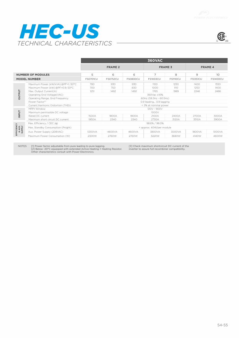
360VAC
FRAME 2 FRAME 3 FRAME 4
NUMBER OF MODULES 5 6 6 7 8 9 10MODEL NUMBER FS0701CU FS0752CU FS0830CU FS1003CU FS1110CU FS1251CU FS1400CU
[1] Power factor adjustable from pure leading to pure lagging. [2] Below -20°C equipped with extended Active Heating + Heating Resistor.Other characteristics consult with Power Electronics.
NOTES [3] Check maximum shortcircuit DC current of the inverter to assure full recombiner compatibility.
OU
TPU
T
Maximum Power (kW/kVA) @PF=1; 50°C 780 930 930 1100 1250 1400 1550Maximum Power (kW) @PF=0.9; 50°C 700 750 830 1000 1110 1250 1400Max. Output Current(A) 1251 1492 1492 1765 1989 2246 2486Operating Grid Voltage(VAC) 360Vac ±10%Operating Range, Grid Frequency 60Hz (59.3Hz - 60.5Hz)Power Factor[1] 0.9 leading... 0.9 laggingCurrent Harmonic Distortion (THDi) < 3% at nominal power
INP
UT
MPPt Window 510V - 900VMaximum permissible DC voltage 1000VRated DC current 1500A 1800A 1800A 2100A 2400A 2700A 3000AMaximum short circuit DC current 1950A 2340 2340 2730A 3120A 3510A 3900A
EFF
ICIE
NC
Y &
AU
X.
SUP
PLY
Max. Efficiency / CEC (η) 98.6% / 98.0%
Max. Standby Consumption (Pnight) < approx. 40W/per module
Aux. Power Supply (208VAC) 5300VA 4600VA 4600VA 3800VA 3000VA 1800VA 1000VA
Maximum Power Consumption (W) 2300W 2760W 2760W 3220W 3680W 4140W 4600W
HEC-USTECHNICAL CHARACTERISTICS

SG 60KU-M
Efficiency Curve
Effi
cien
cy
Normalized Output Power
90%
92%
94%
96%
98%
100%
0% 20% 40% 60% 80% 100%
Vdc=550V
Vdc=710V
Vdc=850V
MPP trackers and a wide input voltage range
Output power up to 66kVA / 66kW at power factor of 1
Can be installed at any angle
CSA C22.2 107.1-01-2001, FCC Part 15 Sub-part B
Class B Limits
OHSAS 18000
Efficient and flexible
ReliableIntegrated combiner box: 16 x Screw terminal pairs
with DC string fuses (both positive and negative), Type
II overvoltage protection(both DC and AC), DC and
AC switch, more safety and lower the system cost
Integrated string detection function and arc fault
detection
Intelligent design
Active power continuously adjustable (0~100%)
requirments with power factor 0.8 overexited ~ 0.8
underexited
Integrated LVRT and HVRT function
Includes RS-485 and Ethernet interface, compatible
with all common monitoring systems
Grid-friendly
www.sungrowpower.com
PV Grid-Connected Inverters 2015~2016 V121
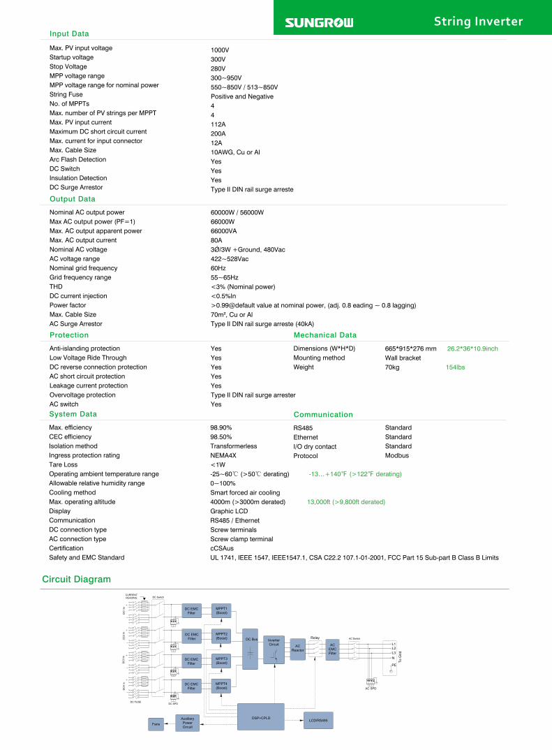
Max. PV input voltageStartup voltageStop VoltageMPP voltage rangeMPP voltage range for nominal powerString FuseNo. of MPPTsMax. number of PV strings per MPPTMax. PV input currentMaximum DC short circuit currentMax. current for input connectorMax. Cable SizeArc Flash DetectionDC SwitchInsulation DetectionDC Surge Arrestor
String InverterInput Data
Output Data
Protection
System Data Communication
Mechanical Data
Nominal AC output powerMax AC output power (PF=1)Max. AC output apparent powerMax. AC output currentNominal AC voltageAC voltage rangeNominal grid frequencyGrid frequency rangeTHDDC current injectionPower factorMax. Cable SizeAC Surge Arrestor
Anti-islanding protectionLow Voltage Ride ThroughDC reverse connection protectionAC short circuit protectionLeakage current protectionOvervoltage protectionAC switch
Max. efficiencyCEC efficiencyIsolation methodIngress protection ratingTare LossOperating ambient temperature rangeAllowable relative humidity rangeCooling methodMax. operating altitudeDisplayCommunicationDC connection typeAC connection typeCertificationSafety and EMC Standard
RS485EthernetI/O dry contactProtocol
Dimensions (W*H*D)Mounting methodWeight
1000V 300V 280V 300~950V550~850V / 513~850V Positive and Negative 4 4 112A 200A 12A 10AWG, Cu or Al Yes Yes Yes
Type II DIN rail surge arreste
60000W / 56000W66000W66000VA80A3Ǿ/3W +Ground, 480Vac 422~528Vac 60Hz55~65Hz<3% (Nominal power) <0.5%In >0.99@default value at nominal power, (adj. 0.8 eading ~ 0.8 lagging) 70m², Cu or Al Type II DIN rail surge arreste (40kA)
Yes Yes Yes Yes Yes Type II DIN rail surge arresterYes
98.90%98.50%TransformerlessNEMA4X<1W -25~60 (>50 derating) -13…+140 (>122 derating) 0~100% Smart forced air cooling4000m (>3000m derated) 13,000ft (>9,800ft derated)Graphic LCD RS485 / Ethernet Screw terminals Screw clamp terminalcCSAusUL 1741, IEEE 1547, IEEE1547.1, CSA C22.2 107.1-01-2001, FCC Part 15 Sub-part B Class B Limits
Standard Standard Standard Modbus
665*915*276 mm 26.2*36*10.9inchWall bracket70kg 154lbs
Circuit Diagram
DC SwitchCURRENTREADING
DC
1 In MPPT1
(Boost)
L2
N
PE
L1
L3
LCD/RS485DSP+CPLD
MPPT2(Boost)
MPPT3(Boost)
MPPT4(Boost)
DC
2 In
DC
3 In
DC
4 In
DC EMC Filter
DC EMC Filter
DC EMC Filter
DC EMC Filter
DC SPDDC FUSE
FansAuxiliary Power Circuit
DC Bus InverterCircuit AC
Reactor
Relay
ACEMCFilter
To G
rid
AC Switch
AC SPD

solarworld.com
SW 340-350 XL MONO
Designed to withstand heavy accumulations of snow and ice
Every component is tested to meet 3 times IEC requirements
SunmodulePositive performance tolerance
25-year linear performance warranty and 10-year product warranty
Glass with anti-reflective coating
-0/+5 Wp
Anti-ReflectiveCoating
TUV Power controlled: Lowest measuring tolerance in industry
World-class qualityFully-automated production lines and seamless monitoring of the process and material ensure the quality that the company sets as its benchmark for its sites worldwide.
SolarWorld Plus-SortingPlus-Sorting guarantees highest system efficiency. SolarWorld only delivers modules that have greater than or equal to the nameplate rated power.
25-year linear performance guarantee and extension of product warranty to 10 yearsSolarWorld guarantees a maximum performance digression of 0.7% p.a. in the course of 25 years, a significant added value compared to the two-phase warranties common in the industry, along with our industry-first 10-year product warranty.*
*in accordance with the applicable SolarWorld Limited Warranty at purchase.www.solarworld.com/warranty
geprüteSicherheit
• Qualified, IEC 61215• Safety tested, IEC 61730• Blowing sand resistance, IEC 60068-2-68• Ammonia resistance, IEC 62716• Salt mist corrosion, IEC 61701• Periodic inspection
• Periodic inspection• Power controlled
SW-01-7540US-I 160324All units provided are imperial. SI units provided in parentheses. SolarWorld AG reserves the right to make specification changes without notice.
Mod
ule
curr
ent [
A]
Module voltage [V]
1000 W/m²
800 W/m²
600 W/m²
400 W/m²
200 W/m²
100 W/m²
ISC
VOC
COMPONENT MATERIALS
Cells per module 72 Front Low-iron tempered glass with ARC (EN 12150)
Cell type Monocrystalline Frame Clear anodized aluminum
Cell dimensions 6.17 in x 6.17 in (156.75 x 156.75 mm) Weight 47.6 lbs (21.6 kg)
PERFORMANCE UNDER STANDARD TEST CONDITIONS (STC)*
SW 340 SW 345 SW 350
Maximum power Pmax 340 Wp 345 Wp 350 Wp
Open circuit voltage Voc 47.6 V 47.8 V 48.0 V
Maximum power point voltage Vmpp 38.0 V 38.2 V 38.4 V
Short circuit current Isc 9.69 A 9.75 A 9.82 A
Maximum power point current Impp 9.01 A 9.10 A 9.17 A
Module efficiency m 17.04 % 17.29 % 17.54 %
*STC: 1000W/m², 25°C, AM 1.5
PERFORMANCE AT 800 W/M2, NOCT, AM 1.5
SW 340 SW 345 SW 350
Maximum power Pmax 259.3 Wp 263.8 Wp 267.2 Wp
Open circuit voltage Voc 41.5 V 41.8 V 42.0 V
Maximum power point voltage Vmpp 34.9 V 35.2 V 35.4 V
Short circuit current Isc 8.05 A 8.10 A 8.16 A
Maximum power point current Impp 7.42 A 7.50 A 7.56 A
Minor reduction in efficiency under partial load conditions at 25 C: at 200 W/m2, 100% of the STC efficiency (1000 W/m2) is achieved.
THERMAL CHARACTERISTICS
NOCT 46 C
TCIsc 0.042 % / C
TCVoc -0.304 % / C
TCPmpp -0.43 % / C
Operating temp -40 to +85 °C
ADDITIONAL DATA
Power sorting -0 Wp/+5 Wp
J-Box IP65
Connector PV wire per UL4703 with H4/UTX connectors
Module fire performance (UL 1703) Type 1
PARAMETERS FOR OPTIMAL SYSTEM INTEGRATION
Maximum system voltage SC II / NEC 1000 V
Maximum reverse current 25 A
Number of bypass diodes 3
Design loads* Two rail system 113 psf downward, 64 psf upward
Design loads* Edge mounting 178 psf downward, 23 psf upward
* Please refer to the Sunmodule installation instructions for the details associated with these load cases.
• Compatible with both "Top-Down" and "Bottom" mounting methods
• Grounding Locations:– 4 locations along the length of the
module in the extended flange.
1.14 (29)
0.43 (11)
1.30 (33)
SW 340-350 XL MONO
+-
78.4
6 (19
93)
4x
37.8 (961)
47.2
4 (12
00)
∅ 0.26 (6.6)
∅ 0.35 (9)
0.39 x 0.27(10 x 7) (4)
11.53(292.85)
15.63(397)
15.63(397)
15.75(400)
4.20(106.65)
15.73(399.50)
∅ 0.35 (9)
39.4 (1001)1.30 (33)

/ΘΠΘ/ΩΝςΚ5ΘΝΩςΚΘΠΥ
/#:+/7/∋((+%+∋0%;
9219∋41762764#0)∋ +ΦΓΧΝΗΘΤΝΧΤΙΓΥΕΧΝΓΚΠΥςΧΝΝΧςΚΘΠΥ
∗ΚΙϑΡΘΨΓΤΗΩΝΗΘΘςΡΤΚΠςΤΓΦΩΕΓΥΚΠΥςΧΝΝΧςΚΘΠςΚΟΓΧΠΦ∃15ΕΘΥςΥ87.8+∋%ΕΓΤςΚ↵ΓΦ
1ΠΓΘΗςϑΓΚΠΦΩΥςΤ[∂ΥΟΘΥςςΤΩΥςΓΦΟΘΦΩΝΓΥ(ΚΓΝΦΡΤΘΞΓΠΡΓΤΗΘΤΟΧΠΕΓ
%ΓΤςΚ↵ΓΦςΘΨΚςϑΥςΧΠΦΕϑΧΝΝΓΠΙΚΠΙΓΠΞΚΤΘΠΟΓΠςΧΝΕΘΠΦΚςΚΘΠΥ2ΧΨΚΠΦΝΘΧΦ2ΧΥΠΘΨΝΘΧΦΟΟϑΧΚΝΥςΘΠΓΥΧςΜΟϑ
%∋../7.6+%4;56#..+0∋/1&7.∋
∗ΚΙϑΝ[ΤΓΝΚΧ∆ΝΓΦΩΓςΘΥςΤΚΠΙΓΠςΣΩΧΝΚς[ΕΘΠςΤΘΝ1ΞΓΤΚΠϑΘΩΥΓςΓΥςΥ786%∗(ΧΠΦΟΧΠ[ΟΘΤΓ+ΠϑΘΩΥΓςΓΥςΚΠΙΙΘΓΥΨΓΝΝ∆Γ[ΘΠΦΕΓΤςΚ↵ΕΧςΚΘΠΤΓΣΩΚΤΓΟΓΠςΥ2+&ΤΓΥΚΥςΧΠς
6∗∋
/1&7.∋
%∋46+(+%#6+10
65/Α∋0ΑΑ∃
%#76+104∋#&5#(∋6;#0&+056#..#6+10+05647%6+105∃∋(14∋75+0)6∗∋241&7%66ΤΚΠΧ5ΘΝΧΤ.ΚΟΚςΓΦ#ΝΝΤΚΙϑςΥΤΓΥΓΤΞΓΦ5ΡΓΕΚ↵ΕΧςΚΘΠΥΚΠΕΝΩΦΓΦΚΠςϑΚΥΦΧςΧΥϑΓΓςΧΤΓΥΩ∆ΛΓΕςςΘΕϑΧΠΙΓΨΚςϑΘΩςΠΘςΚΕΓ
+8%748∋51(28/1&7.∋9
6∋/2∋4#674∋4#6+0)5
0ΘΟΚΠΧΝ1ΡΓΤΧςΚΠΙ%ΓΝΝ6ΓΟΡΓΤΧςΩΤΓ01%6
%%
6ΓΟΡΓΤΧςΩΤΓ%ΘΓΗ↵ΕΚΓΠςΘΗ2/#: %
6ΓΟΡΓΤΧςΩΤΓ%ΘΓΗ↵ΕΚΓΠςΘΗ81% %
6ΓΟΡΓΤΧςΩΤΓ%ΘΓΗ↵ΕΚΓΠςΘΗ+5% %
2#%−#)+0)%10(+)74#6+10
/ΘΦΩΝΓΥΡΓΤ∆ΘΖΡΚΓΕΓΥ
/ΘΦΩΝΓΥΡΓΤ∂ΕΘΠςΧΚΠΓΤΡΚΓΕΓΥ
/#:+/7/4#6+0)5
1ΡΓΤΧςΚΘΠΧΝ6ΓΟΡΓΤΧςΩΤΓ %
/ΧΖΚΟΩΟ5[ΥςΓΟ8ΘΝςΧΙΓ
8&%+∋%8&%7.
/ΧΖ5ΓΤΚΓΥ(ΩΥΓ4ΧςΚΠΙ #
9#44#06;
[ΓΧΤ2ΤΘΦΩΕς9ΘΤΜΟΧΠΥϑΚΡ9ΧΤΤΧΠς[
[ΓΧΤ.ΚΠΓΧΤ2ΘΨΓΤ9ΧΤΤΧΠς[
2ΝΓΧΥΓΤΓΗΓΤςΘΡΤΘΦΩΕςΨΧΤΤΧΠς[ΗΘΤΦΓςΧΚΝΥ
/∋%∗#0+%#.#
5ΘΝΧΤΕΓΝΝΥ /ΩΝςΚΕΤ[ΥςΧΝΝΚΠΓΟΟΚΠΕϑΓΥ
%ΓΝΝΘΤΚΓΠςΧςΚΘΠ ΕΓΝΝΥ
/ΘΦΩΝΓΦΚΟΓΠΥΚΘΠΥ ΟΟΚΠΕϑΓΥ
9ΓΚΙϑς ΜΙΝ∆
)ΝΧΥΥ ΟΟ∗ΚΙϑ6ΤΧΠΥΟΚΥΥΚΘΠ#4%ΘΧςΓΦ6ΓΟΡΓΤΓΦ)ΝΧΥΥ
∃ΧΕΜΥϑΓΓς 9ϑΚςΓ
(ΤΧΟΓ 5ΚΝΞΓΤ#ΠΘΦΚ∴ΓΦ#ΝΩΟΚΠΚΩΟ#ΝΝΘ[
,∃ΘΖ +2ΘΤ+2ΤΧςΓΦ
%Χ∆ΝΓΥ 2ϑΘςΘΞΘΝςΧΚΕ6ΓΕϑΠΘΝΘΙ[ΕΧ∆ΝΓΟΟ⟩ΚΠΕϑΓΥ⟩ΟΟΚΠΕϑΓΥ
%ΘΠΠΓΕςΘΤ 76:#ΟΡϑΓΠΘΝ
%ΩΤΤΓΠς#
8ΘΝςΧΙΓ8
ϭϬϬϬtŵϮ
ϴϬϬtŵϮ
ϲϬϬtŵϮ
ϰϬϬtŵϮ
ϮϬϬtŵϮ
6∗∋/1&7.∋
∋.∋%64+%#.#56%
2ΓΧΜ2ΘΨΓΤ9ΧςςΥ2/#:9Ρ
2ΘΨΓΤ1ΩςΡΩς6ΘΝΓΤΧΠΕΓ2/#:9
/ΧΖΚΟΩΟ2ΘΨΓΤ8ΘΝςΧΙΓ8/228
/ΧΖΚΟΩΟ2ΘΨΓΤ%ΩΤΤΓΠς+/22#
1ΡΓΠ%ΚΤΕΩΚς8ΘΝςΧΙΓ81%8
5ϑΘΤς%ΚΤΕΩΚς%ΩΤΤΓΠς+5%#
/ΘΦΩΝΓ∋Η↵ΕΚΓΠΕ[ Ο
56%+ΤΤΧΦΚΧΠΕΓ9Ο⟩%ΓΝΝ6ΓΟΡΓΤΧςΩΤΓ%#ΚΤ/ΧΥΥ#/
∋.∋%64+%#.#01%6
/ΧΖΚΟΩΟ2ΘΨΓΤ2/#:9Ρ
/ΧΖΚΟΩΟ2ΘΨΓΤ8ΘΝςΧΙΓ8/228
/ΧΖΚΟΩΟ2ΘΨΓΤ%ΩΤΤΓΠς+/22#
1ΡΓΠ%ΚΤΕΩΚς8ΘΝςΧΙΓ81%8
5ϑΘΤς%ΚΤΕΩΚς%ΩΤΤΓΠς+5%#
01%6+ΤΤΧΦΚΧΠΕΓΧς9Ο⟩#Ο∆ΚΓΠς6ΓΟΡΓΤΧςΩΤΓ%9ΚΠΦ5ΡΓΓΦΟΥ
65/2&
(ΚΤΓ6[ΡΓ 6[ΡΓΘΤ
65/Α∋0ΑΑ#
6ϑΓΟΓΕϑΧΠΚΕΧΝΝΘΧΦΚΠΙΚΥΦΓΡΓΠΦΓΠςΩΡΘΠςϑΓΟΘΩΠςΚΠΙΟΓςϑΘΦ6ϑΓΟΘΩΠςΚΠΙΟΓςϑΘΦΦΓΥΕΤΚ∆ΓΦΚΠςϑΓ+ΠΥςΧΝΝςΚΘΠ/ΧΠΩΧΝΥΓΕςΚΘΠ%ΕΧΠΡΧΥΥ2ΧΨΚΠΦΝΘΧΦΧΠΦ2ΧΥΠΘΨΝΘΧΦ
&+/∋05+1051(28/1&7.∋
∃ΧΕΜ8ΚΓΨ
##
,70%6+10∃1:
0#/∋2.#6∋
+056#..+0)∗1.∋
)4170&+0)∗1.∋
&4#+0∗1.∋
ΩΠΚςΟΟΚΠ
##
5ΚΝΚΕΘΠ5ΓΧΝΧΠς
.ΧΟΚΠΧςΓ
(ΤΧΟΓ
+ΠΥςΧΝ ΝΚΠΙ∗ΘΝΓΥΖΖ
+ΠΥςΧΝ ΝΚΠΙ∗ΘΝΓΥΖΖ
PLAN VIEW
ELEVATION
436"
449"
139"
INVERTER
INVERTER
TRANSFORMER
AUX
EQU
IPM
ENT
INVERTERTRANSFORMER89"
INVERTER SKID PLAN AND PROFILE
Brooklyn
Canterbury
Griswold
Killingly
Plainfield
Route 6 Connector
!V205
!V49
!V14A
!V169 !V12
!V14
£¤6
§¦395
§¦395
Exit 87
Exit 88Exit 88
Exit 90
Exit 87
Exit 89Exit 89
B 68Brooklyn
B 71Plainfield
A 78Gallup
11/13/2015
A 84Hopeville
Road
A 84Hopeville Road
1/15/2012
A 84Hopeville Road
4/24/2012
RhodeIsland
December 28, 2015
NOTE: The Aquifer Protection Areas weredelineated through Connecitcut's Level Aand Level B Mapping Processes. AquiferProtection Areas are delineated for activepublic water supply wells in stratified driftthat serve more than 1000 people, in accordance with Sections 22a-354cand 22a-354z of the ConnecticutGeneral Statutes. Level B Mappingdelineates a preliminary aquiferprotection area, providing an estimate of the land area from which the well draws its water. Level A Mappingdelineates the final Aquifer ProtectionArea, which becomes the regulatoryboundary for land use controls designedto protect the well from contamination.As Level A Mapping is completed for each well field and approved by DEEP,it replaces the Level B Mapping. Final Adopted Level A Areas are thosewhere towns have land use regulationsfor them.Masschusetts and Rhode Island WellheadProtection Areas may be shown forinformational purposes.QUESTIONS: Bureau of Water Protection and Land Reuse Planning and Standards DivisionPhone: (860) 424-3020www.ct.gov/deep/aquiferprotection
Plainfield, CT
AQUIFER PROTECTIONAREAS
STATE OF CONNECTICUTDEPARTMENT OF ENERGY & ENVIRONMENTAL PROTECTION79 Elm StreetHartford, CT 06106-5127
Level A APA (Final Adopted)Level A APA (Final)Level B APA (Preliminary)Town Boundary
$
Steve Broyer
Rectangle
Steve Broyer
Callout
PROJECT AREA
HIGHLAND SOILS LLC
WETLAND REPORT
PLAINFIELD PIKE SOLAR FACILITY91 PLAINFIELD PIKE
PLAINFIELD, CONNECTICUT
PREPARED FORECOS ENERGY
BYJOHN P. IANNI
PROFESSIONAL SOIL SCIENTIST
APRIL 27, 2016
P.O Box 337, Storrs, CT 06268 ∙ 860-742-5868 ∙ [email protected]

2P.O Box 337, Storrs, CT 06268 ∙ 860-742-5868 ∙ [email protected]
INTRODUCTION
The project site contains just over 69 acres and is located on the south side of Plainfield PikeRoad and westerly of Interstate 396 in Plainfield, CT. The site is currently wooded and slopes in ageneral east to west direction. In the fall of 2015 the inland wetland boundaries were fielddelineated and in March and April of 2016 additional site walks were conducted to collectinformation on the natural resources of the site.
The inland wetland delineation on the subject property was completed on August 30, 2015.The wetlands were field delineated in accordance with the standards of the National CooperativeSoil Survey and the definition of wetlands as found in the Connecticut General Statutes, Chapter440, Section 22A-38. I have reviewed the prepared plans have found the representation of the fielddelineated wetlands to be substantially correct.
The eastern-most wetland line was flagged as part of the 2015 wetland survey, however, aprevious wetland survey was conducted on the property and the eastern-most line is from theprevious survey. Most of the previous flags were visible and the more recent line is in generalagreement with the older line.
Additionally, the wetland boundaries also conform to the jurisdictional wetlands definition(Federal or Army Corps wetlands) as based on:
Environmental Laboratory. 1987. “Corps of Engineers WetlandsDelineation Manual,” Technical Report Y-87-1, US Army EngineerWaterways Experiment Station, Vicksburg, Miss.
EXISTING CONDITIONS
The subject property is currently wooded with mixed hardwood species. A small loggingoperation has been ongoing on the property since the summer of 2015 and a selective harvest ofhardwoods for firewood has removed most of the Ash trees and some Oaks. The operation wasmainly concentrated in the eastern third of the site where the trees were cut and then skidded to aprocessing area on the adjacent property to the east. Small skid roads traverse the site, includingwetland areas. However, minimal disturbance to the soils was observed in the spring of 2016.
As stated earlier, the site slopes from east to west and two watercourse systems traversethe site. The site contains a small area of sand and gravel dominated soils in the northeasternlimits of the site, but glacial till dominates the soil resources.
The site consists of two parcels of land that are very distinguishable based on historicland uses, which have impacted the current vegetative communities. The eastern third of the sitecontains an understory dominated by Japanese barberry with Multiflora rose thickets. Older fieldareas also contain Multiflora rose and Honeysuckle, the species are indicative of a transitionfrom agriculture to the present woodlands. The western third of the property contains a moremature Oak/Hickory growth with less of the invasive species. The understory is more open inthe western portion of the property and the forest is more typical of areas that have not been usedfor agriculture in the recent past.

3P.O Box 337, Storrs, CT 06268 ∙ 860-742-5868 ∙ [email protected]
WETLAND RESOURCES
The mapped wetlands comprise approximately a quarter of the site. Two perennialwatercourses enter and exit the site, and although they combine offsite, they originate fromdifferent drainage areas. The main wetland feature on the site is a large system that is found inthe eastern third of the site. Along the southeastern property line a small intermittent or seasonalwatercourse enters the site and flows northerly toward the main body of the wetland. Thewatercourse hugs the western edge of the wetland before it exits and reenters from the abuttingDodge property. The eventual discharge is off the property along the southern property line.The watercourse channel is well defined through the upper portion of the wetlands where it isbuffered by wide areas of poorly drained or wetland soils. After the watercourse renters theproperty it is in a well-defined but small channel with just a narrow strip of wetland soils alongits edges. No evidence of overbank flow was noted along the lower channel, and surface flowsappear diminished by the capacity of the main body of wetlands to store surface water afterprecipitation events.
The main body of the wetland is along the northern property line where a perennialwatercourse also enters the property. The perennial watercourse enters the wetland system alongthe northern border near the northeastern corner of the abutting church property. Ground waterseepage wetlands were noted to the east of the watercourses. The water course channel is welldefined and recent overbank flows were noted. The ground surface is very stony and flat and thewatercourse channel tends to flow along the western edge of the mapped wetlands. Thevegetation begins to transition at this point and along with Red maple, Winterberry begins toappear in the understory. The ground cover includes Sphagnum moss, Skunk cabbage, Falsehellsbore, Sensitive fern and Blue flag iris. Japanese barberry is still present in this area.Surface water flow outside of the defined channel is diffuse and evidence of ponding afterprecipitation events is apparent in the main wetland body. A small upland island was mappedadjacent to the perennial watercourse.
The ground water seepage wetlands are wooded with Red maple as the dominant treespecies. The understory reflects the agricultural history of the property and Multiflora rose isprevalent, but Japanese barberry dominates the wetland boundaries and drier portions of thewetland. Spicebush is also present but the barberry forms the majority of the understory. In theinterior of the wetland where openings in the canopy allow for more light penetration, Soft rushand Woolgrass are found. Oaks, Hickory and Ash are also present in the wetland and are areflection of the seasonally fluctuating water table within the wetlands.
The wetland system narrows as the topographic gradient increases. The next fewhundred feet of wetlands are characterized by the perennial watercourse and a small buffer ofwetland soils. The vegetation also transitions to a more mature mixed hardwood system. Thechannel size decreases as the topographic gradient increases and overbank flows are not asapparent.

4P.O Box 337, Storrs, CT 06268 ∙ 860-742-5868 ∙ [email protected]
The wetland system flows westerly to a large flat area where flows are dissipated and thechannel size decreases and turns to the south before discharging off the property in thesouthwestern portion of the property. At the property line, an existing stone wall acts as a smallconstriction in the system and overbank flows are apparent.
A separate wetland system was observed along the northwestern corner of the property.It should be noted that although the hydrology of this wetland system is separate from the mainbody of wetlands, there is a connection between the two wetlands that results in a continuouswetland mapping between the two areas. The two systems do not have a surface flowconnection, and a distinct drainage divide was noted between the systems. This wetland isassociated with a perennial watercourse that enters the subject property from the StateDepartment of Transportation property located in the northwestern corner of the site. Thewetland associated with the watercourse is a Red maple/Highbush blueberry, Sweet pepperbushplant community with very poorly drained soils that are saturated to the surface for most of theyear.
The final wetland is an isolated area of poorly drained soils located along the southernproperty line. This wetland system has a seasonally high water table but is not associated withany surface water or surface flows. The vegetation consists of mixed hardwoods that includeRed maple, White oak and Shagbark hickory. American beech is in the understory and thewetland is supported by shallow ground water flows.
VERNAL POOL HABITAT
On March 30, 2016 a survey for breeding amphibians was conducted on the property.Skies were mostly cloudy in the morning with clearing skies in the afternoon. Temperaturesranged from the upper 40’s F to the upper 50’s by late afternoon. Three areas of breedingamphibians were found within the mapped wetlands.
A second survey was conducted on April 13, 2016. Temperatures were around 55degrees F and skies were sunny.
It should be noted that Vernal Pool Assessments (Assessment Sheets attached) wereconducted in accordance with the methodology contained in the following publication, hereafterreferred to as the BDP (Best Development Practices):
Calhoun, A. J. K. and M. W. Klemens. 2002. Best development practices:Conserving pool-breeding amphibians in residential and commercialdevelopments in the northeastern United States. MCA Technical Paper No. 5,Metropolitan Conservation Alliance, Wildlife Conservation Society, Bronx, NewYork.
Area #1 is located in a small area of standing surface water adjacent to wetland flag #23.The area of surface water was approximately 10 feet by 20 feet and up to a foot in depth. Thearea is adjacent to diffuse surface flows within the mapped wetlands but the hydrology appearsto be supported by shallow ground water flows. Eleven Wood frog egg masses were noted in a
5P.O Box 337, Storrs, CT 06268 ∙ 860-742-5868 ∙ [email protected]
cluster along the edge of the pool. A single Spotted salamander egg mass was also seen in thesecond survey. A small area of shallow standing water was noted just north of the breeding area;this area does not contain wetland soils and no breeding activity was noted.
The second area of breeding amphibians was found in the center of the southeasternwetland finger and is located equidistant from wetland flags #136 and #C39. The breeding poolis an older man-made excavation adjacent to the seasonal watercourse. The pool isapproximately 15 feet in diameter and up to two feet deep. It is clearly man-made and the spoilsare located along all the edges. The spoils separate the surface flow of the intermittentwatercourse from the ground water-fed breeding pool. In this breeding area 18 Spottedsalamander egg masses and eleven Wood frog egg masses were noted.
The third breeding area is located approximately 100 feet to the south along the westernedge of the mapped wetlands. A small depression with shallow ponding of less than one footwas noted and two Spotted salamander egg masses and four Wood frog egg masses were noted.
All three of the pools are rated as Tier I based on the Vernal Pool Assessment.
Individual Wood frog and Spotted salamander egg masses were scattered throughout theupper or eastern portion of the wetland and are associated with small micro-pools and shallowponded areas created by previous logging activities.
WETLAND FUNCTIONS
The functions and values of the wetlands will be described in a qualitative mannermodeled after the method used by the US Army Corps of Engineers. The information is fromThe Highway Methodology Workbook Supplement. This publication uses a descriptive approachto assessing functional values, versus the CT D.E.P. approach, which uses a quantitative ornumerical approach to ranking wetland functions and values.
Ground Water Recharge/Discharge - This function considers the potential for a wetland to serveas a ground water recharge and/or discharge area. It refers to the fundamental interactionbetween wetlands and aquifers, regardless of the size or importance of either.
Ground water seepage into the wetlands through shallow ground water flows occurs inthe upper part of the wetland. Surface inputs in the form of watercourses are found inthree locations and there are two discharge points at the property boundaries. Thewetlands are underlain by a sandy and friable glacial till and there are signs of decreasedsurface flows in the wetlands. The wetlands are ground water discharge wetlands with acomponent of shallow ground water recharge in places. Ground water recharge anddischarge are a primary function of the on-site wetlands.
Floodflow Alteration - This function considers the effectiveness of the wetland in reducing flooddamage by water retention for prolonged periods following precipitation events and the gradualrelease of flood waters. It adds to the stability of the wetland ecological system or its buffering

6P.O Box 337, Storrs, CT 06268 ∙ 860-742-5868 ∙ [email protected]
characteristics and provides social or economic value relative to erosion and/or flood proneareas.
Areas of the wetlands are flat and signs of overbank flows are present. Signs of variablewater levels are also present and there is a constricted outlet to the main wetland on theproperty. Channel sizes vary within the wetlands with larger areas suitable for storage ofexcess storm flows. Poorly drained soils are located adjacent to the watercourses and arecapable of storing water during precipitation events. This function occurs to a highdegree in the upper and lower portion of the wetlands.
Fish and Shellfish Habitat - This function considers the effectiveness of seasonal or permanentwatercourses associated with wetland in question for fish and shellfish habitat.
The watercourses associated with the wetlands are small and although they are persistent,perennial flows are limited to the wetland in the northwestern corner. This system hasculverts at the inlet to the property and outlet. Significant barriers to fish movement arepresent. The main wetland system is associated with more seasonal flows and is notsuitable for fish habitat. Stone walls and off-site culverts form significant barriers forfish movements. No evidence of fish was present but an extensive survey was notconducted. This is not a primary function of the on-site wetlands.
Sediment/Toxicant/Pathogen Retention - This function reduces or prevents degradation of waterquality. It relates to the effectiveness of the wetland as a trap for sediments, toxicants orpathogens in runoff water from surrounding uplands, or upstream eroding wetland areas.
The potential for sediment sources exist in the watershed above this wetland. Althoughassociated with watercourses, there are many indications of overbank flows during smallstorm events. The surface flows outside of the defined channels are diffuse and themicro-topography allows for sediment capture. Velocity decreases are apparent in thewetlands and the opportunity for sediment capture at constriction points is apparent. Thewetlands lack a high degree of open water vegetation interspersion but sediment capturewas apparent. This is a main function of the wetlands.
Nutrient Removal/Retention/Transformation - This function considers the effectiveness of thewetland as a trap for nutrients in runoff water from surrounding uplands or contiguous wetlands,and the ability of the wetlands to process these nutrients into other forms or trophic levels. Oneaspect of this function is to prevent ill effects of nutrients entering aquifers or surface waterssuch as ponds, lakes, streams, rivers or estuaries.
The ability for the wetlands to perform this function is limited by the watercourses thatflow through the wetland. During normal flows the watercourse conveys flows throughthe wetland and there is little opportunity for nutrient capture and uptake. During stormflows, overbank flows saturate the surrounding wetlands and nutrient capture can occur.However, the lack of sufficient areas of open water and the lack of diversity andabundance of aquatic plants limits the function. The wetland system in the northwestern

7P.O Box 337, Storrs, CT 06268 ∙ 860-742-5868 ∙ [email protected]
corner of the site has the ability to perform this function while the main wetland systemdoes not. This is a primary function for small portions of the on-site wetlands.
Production Export - This function relates to the effectiveness of the wetland to produce food orusable products for human, or other living organisms.
Only the wetland system in the northwestern part of the property has enough qualifiersfor this to be a consideration. This wetland has a dense shrub layer of berry-producingshrubs and the production of organic matter is high. The remaining wetland system haslittle potential for organic matter production and export due to its thin canopy of trees andsparse shrub layer other than Barberry. The potential for flushing of the wetlands islimited other than the northwestern system. This is not a principle function.
Sediment/Shoreline Stabilization - This function evaluates the effectiveness of a wetland tostabilize stream banks and shorelines against erosion.
The on-site wetlands are not associated with a pond, lake or other water body. Thewatercourse channels are stable and no unusual erosion was noted. The wetlandsgenerally have very stony surfaces and topographic gradients are generally low. This isnot a primary function.
Wildlife Habitat - This function considers the effectiveness of the wetland to provide habitat forvarious types and populations of animals typically associated with wetlands and wetland edges.Both resident and/or migrating species are considered.
The wetlands are a single cover class and lack interspersion of other wetland types. Openwater areas and marsh habitat are lacking. Density of vegetation is high in some areasbut the wetlands generally have open understories. Aquatic vegetation and multiplecover classes are generally lacking. Interstate 395 is along the western border of the siteand connectivity to other wetland areas is fragmented by the highway and other roads.Wildlife utilization of the site occurs but it is not a primary function of the wetlands.
Recreation – (Consumptive and Non-Consumptive) This value considers the suitability of thewetland and associated watercourses to provide recreational opportunities such as hiking,canoeing, boating, fishing, hunting and other active or passive recreational activities.
The wetlands are not associated with a river, stream, pond or other feature that wouldaccommodate water-based recreation such as fishing, canoeing or boating. The watercourses are not of sufficient size for swimming or other active recreation. The wetlandsare not wildlife habitat wetlands and this function is not present on the site.
Educational/Scientific Value - This function considers the suitability of the wetland as an“outdoor classroom” or for scientific research.
The wetlands have low potential for this function. The site is not part of an educationalsite and lacks the diversity in wetland classes. The site is not readily accessible and has a

8P.O Box 337, Storrs, CT 06268 ∙ 860-742-5868 ∙ [email protected]
high degree of invasive plants. No significant open water areas exist and the recentlogging has resulted in a disturbed appearance. The site lacks significant cultural featuresand access to the site is not available. This is not a primary value.
Uniqueness/Heritage - This value considers the effectiveness of the wetland for special valuessuch as archeological sites, rare and endangered species habitat or uniqueness for its location.
This value is not represented on the site. The wetlands are generally a single cover classand lack a pond site or other site features that enhance the potential for this value. Thereare no known archeological features, rare and endangered habitat or existing study siteswithin the wetlands. The wetlands have a high degree of invasive plants and views intothe wetlands are limited. Of the 31 qualifiers for this value only a few are representedand they include a well vegetated stream corridor, and potential viewing locations andstone walls. This is not a primary value.
Visual Qualities/Aesthetics - This value relates to the visual qualities of the wetlands.
The wetlands lack the diversity in wetland types including shallow marshes and other lowgrowing open type wetland systems. The site has extensive disturbances due to recentlogging and the presence of large areas of invasive species detracts from this value. Thisis not a primary value.
Endangered Species Habitat – This value considers the suitability of the wetland to supportthreatened or endangered species.
A review of the Natural Diversity Data Base maintained by the State of Connecticutindicates no rare endangered or threatened species on or near the site. An inquiry hasbeen made to the State for additional information and guidance.
WETLAND IMPACTS
Direct Wetland Impacts
Three areas of solar arrays are proposed for the site. Access to the southerly arrayrequires a wetland crossing for an access drive. The drive will cross a relatively narrow area inthe wetland and will utilize a small upland island in the middle of the wetland to minimize thefootprint of the access drive. A low water crossing is proposed (as detailed on the plans). Thecrossing minimizes grading and reduces the footprint of the crossing to the maximum extentpossible. The total direct wetland impact is 4,660 square feet and should be eligible for aCategory 1 permit from the Army Corps of Engineers.
The area of the proposed crossing has been recently disturbed and has been used as alogging road for a harvest operation from the fall of 2015. The wetland in the area of thecrossing has a seasonally high water table but is very dry in the summer months. An intermittentwatercourse is associated with the wetland but only flows during the wet periods in the springand fall.

9P.O Box 337, Storrs, CT 06268 ∙ 860-742-5868 ∙ [email protected]
The original proposal was to have an access road along the northerly property line with aspur to access the southerly array. After a more detailed investigation of the crossing analternative is being explored that would access the northerly array through an abutting property.This alternative access would greatly reduce the initially proposed direct wetland impacts.
Indirect Wetland Impacts
The project has been designed so that all of the solar arrays are outside of wetlands.Minor clearing along the one hundred foot upland review area is proposed and the perimeterfence is within the upland review area. All disturbed areas will be seeded and stabilized withvegetation and long-term impacts have been minimized.
It is recommended that the wetland crossing be conducted during the dry season whenground water levels are low and surface flows are minimal. Additionally, it is recommended thatsite work be minimized in the early spring during the migration and breeding season for theobligate amphibian species. This could be accomplished by avoiding site work near the vernalpools from March through June. Silt fence exclusion barriers can be used to minimize impact tothe amphibian populations during that period.

P\cl,"€\e\dr P\e,
IZEBHLAL p_O_SL_.4SsE_.ss_ngE NT §E±BB
.i. Bi®Iogfcal Vak!e ®f the Vernal Pool
S¥Pe¥LEhorerisj
1Arethereanystate-listedspeciesEndangeeSThatened,orSpecialConcempresentor
:rrc==th]eu¥fl3Aretheretwc®rmorevemalpooEindicatcrspeciesbreedingi.e.,evidencecfeggifiassess
sperm`ajpphores [sperm packets]s mating, iarvae in the pcoi?
3 Are there 25 or more egg masses regardess Gf species) present in theconclusion of the braeYes No
Yesx . N-o
ing seaen?pcol by the
a. Condition of the Critical Terrestrial Habitat
(1Isatle;a;t75%of`thevernalpoolenvelope100feetfrompcolundeveloped?
(2) Is at least 50% of the critical terrestrial habitat 100-750 feet undeveloped?\/Yesx NoNOTE: For these purposes, "undeveloped" means open land largely free of roads,structures, and other infrastructure. It can be forested, partially forested, or openagricultnd land.
CnmtElative Assessment
Number ofquestionsanswered
Number ofquestionsanswered
1! ¥Esin i YEsirJ i Hating fiI
i category Ar category a
[® I © !®_i-3 1 Tier [1
0 I-2 I Tier Ill
I-3 0 Tier Ill
CAIIFI!ORE This rating system is designedstricliy as a planning tool, ncit as an officialassessl#g7z/ /oo/. £t will enable you todetermine the relative ecological value ofpools within your`community. A Tier Irating ..--which wilt most [ike!y apply to only aminority of sitesTndenotes exempEary pools;Frfanagem[er,t P`ecc;Trtif]erldat!cr[s sET]otiid be
applied at these sites. For pco!s rated as TieriE; proceed with care; you need moreinformation! Tier EI pools will probablyconstitute the majority of ,Your venal poolresources; Manage'men€ Recommendaticmsshould be applied at these sites to themaximum extent practicable. Tier EI poolsmight also be likely candidates for restorationefforts e.g.. reforEstation of the crfeica!terrestrial hab ifat.
9
+iiiiiiii

5EBI+FELPPOL_4_§fl2SSELE_rgrs_ETiELg][.i. Biological Valtte ®f the Vernal Po®[
¥¥Lfhereirs!
!)Arethereanystate-listedspecies(Endngered,Theatened,orSpecialConcempesentor
:rr:se=thiTg°|(2AretheretwcormorevemaEpoolindicaterspeciesbFeedingi.e,3evidericeofeggmasses9
______ _,L _ _1 r
[spenn packets]9 mating, larvae in the pcor?
3Arethere25ormoFeeggmassesregardiessGfspeeies)presentinthepcolbythe
;°ensc*Onofifioebre:dingseason?
a. Condition of the Critical Terrestrial Habitat
(1I+eastl#75%Of`thevemalpoolenvelope(100feetfrompcolundeveloped?No
(2"Seast¥0°oNo
of the critical terrestrial habitat 100-750 feet) undeveloped?
NOTE: For these pxpses, .`undeveloped" means open land largely free of roads,structures, and other infrastructure. It can be forested, partially forested, or openagricultunl land.
Cumulative Assessment
I category A . category a
EL_© ® (TT:rji-3 1 Tier I1
0 I-2 ( Tier Ill
I-3 0 Tier Ill
CAJITI!ORE This rating system is designedstrict,y as a p]anr,ing too,, r,ot as an offic;a,c"e£S]#g7f /oo/. It will enable you todetermine the relative ecological value ofpools within your community. A Tier Irating-Lwhich wilt most likely apply to only aminority of sitesTndenotes exemplary poo!s;l#anagem.erLt RecGTrtif]erldatiSris s£Lio-L!id beappli?d at these sites. For pco!s rated as TieriE; proceed u'€th care; you need moreinfomiation! Tier EI pools wi!i probablyconstitute the majority of your vernal poolresoLErces; Management Recommendationsshould be applied at these sites to themaximum extent practicable. Tier 1[ poolsmight also be likely candidates for restorationefforts (e.g.. reforestation of the criticalterrestrial hab itat).
iiiiiiiiii

5EBrleLppOL_4_§sE=ssRIERE_sL±±EB
.i. Biological ValHe of the Vernal Pool
¥egH¥hareies!
1ArethereanystateiistedspeciesEndangered,Theatened,orSpecialConcempesentor
:rr¢:=thi,goK(2AretheretwoormorevemalpooEindicatorspeeiesbreedingi.e.,evidenceOfeggif!assess
______ _i 1 r[sperHi packets]s mating, larvae in the pcoi-?
3)Arethere25ormoFeeggrpjLassesregardessQfspeeies)ppesentinthepcolbythe.-A(,conclusion of the
Yes Nobrfding season?
a. Condition of the Critical Terrestrial Habitat
1)Isatleast75%of`thevemalpoolenvelope100feetfrompcol)undeveloped?Yes x No
2) Is at least 50% of the critical terrestrial habitat 100-750 feet) undeveloped?I,i,YesLjx_ NO
NOTE: For these pulpeses, "undeveloped.' means open land largely free of roads,structures, and other infrastructure. It can be forested, partially forested, or openagricultnd land.
CuimHEative Assessment
Number ofqtiestionsanswered
Number ofquestionsanswered
# YEsiri i YEsiri i i.\a,LL18 i;
I category A i category 8 -_L® ® --,)
1-3 i Tier [1
0 i I-2 , Tier 1II
i-3 0 Tier lrl
9
CA]IFI!ORE This rating system is designedstrjc;fly as a plow,ing tool, not as an official4£sefsmg#f /oo/. £t will enable you todetermine the relative ecological value ofpools within your community. A Tier Irating---which will most likely apply to only aminority Of sitesTutenotes exemplary pools;.ManagemLer.t Recc5TET[merldatiGrts sriot!id beapplied at these sites. For pco[s rated as TieriE; proceed with care; you need moreinformation! Tier EI pools wiii probablyconstitute the majority of .Your venal pcoiresources; Management Recommendationsshould be applied at these sites to themaximum extent practicable. Tier EI poolsmight also be likely candidates for restorationefforts (e.g.. reforestation of the criticalterrestrial habitat).
iiiiiiiiiiiii

![[88713] PLAINTIFF'S DISCOVERY - viethmms.comataa/docs/Interrogatories-1st-to... · provided the information to answer these interrogatories and requests for production. 2. Identify](https://static.fdocuments.net/doc/165x107/5afe72447f8b9a864d8ef440/88713-plaintiffs-discovery-ataadocsinterrogatories-1st-toprovided-the.jpg)


![[88553] DISCOVERY - PLAINTIFF - viethmms.comataa/docs/Interrogatories-1st-to...definitions of that term. INTERROGATORIES DIXIELAND COMPANY INFORMATION If you contend that Plaintiff](https://static.fdocuments.net/doc/165x107/5afe11067f8b9a68498dce7b/88553-discovery-plaintiff-ataadocsinterrogatories-1st-todefinitions-of.jpg)