Performance investigation of advanced adsorption ...
16
This document is downloaded from DR‑NTU (https://dr.ntu.edu.sg) Nanyang Technological University, Singapore. Performance investigation of advanced adsorption desalination cycle with condenser–evaporator heat recovery scheme Thu, Kyaw; Kim, Young Deuk; Myat, Aung; Chakraborty, Anutosh; Ng, Kim Choon 2013 Thu, K., Kim, Y. D., Myat, A., Chakraborty, A., & Ng, K. C. (2013). Performance investigation of advanced adsorption desalination cycle with condenser–evaporator heat recovery scheme. Desalination and Water Treatment, 51(1‑3), 150‑163. https://hdl.handle.net/10356/100406 https://doi.org/10.1080/19443994.2012.693659 © 2013 Desalination Publications. This paper was published in Desalination and Water Treatment and is made available as an electronic reprint (preprint) with permission of Desalination Publications. The paper can be found at the following official DOI: [http://dx.doi.org/10.1080/19443994.2012.693659]. One print or electronic copy may be made for personal use only. Systematic or multiple reproduction, distribution to multiple locations via electronic or other means, duplication of any material in this paper for a fee or for commercial purposes, or modification of the content of the paper is prohibited and is subject to penalties under law. Downloaded on 27 Jan 2022 00:48:31 SGT
Transcript of Performance investigation of advanced adsorption ...

This document is downloaded from DR‑NTU (https://dr.ntu.edu.sg)Nanyang Technological University, Singapore.
Performance investigation of advancedadsorption desalination cycle withcondenser–evaporator heat recovery scheme
Thu, Kyaw; Kim, Young Deuk; Myat, Aung; Chakraborty, Anutosh; Ng, Kim Choon
2013
Thu, K., Kim, Y. D., Myat, A., Chakraborty, A., & Ng, K. C. (2013). Performance investigation ofadvanced adsorption desalination cycle with condenser–evaporator heat recovery scheme.Desalination and Water Treatment, 51(1‑3), 150‑163.
https://hdl.handle.net/10356/100406
https://doi.org/10.1080/19443994.2012.693659
© 2013 Desalination Publications. This paper was published in Desalination and WaterTreatment and is made available as an electronic reprint (preprint) with permission ofDesalination Publications. The paper can be found at the following official DOI:[http://dx.doi.org/10.1080/19443994.2012.693659]. One print or electronic copy may bemade for personal use only. Systematic or multiple reproduction, distribution to multiplelocations via electronic or other means, duplication of any material in this paper for a fee orfor commercial purposes, or modification of the content of the paper is prohibited and issubject to penalties under law.
Downloaded on 27 Jan 2022 00:48:31 SGT

This article was downloaded by: [Nanyang Technological University]On: 09 January 2014, At: 23:33Publisher: Taylor & FrancisInforma Ltd Registered in England and Wales Registered Number: 1072954 Registered office: Mortimer House,37-41 Mortimer Street, London W1T 3JH, UK
Desalination and Water TreatmentPublication details, including instructions for authors and subscription information:http://www.tandfonline.com/loi/tdwt20
Performance investigation of advanced adsorptiondesalination cycle with condenser–evaporator heatrecovery schemeKyaw Thu a , Young-Deuk Kim a , Aung Myat b , Anutosh Chakraborty c & Kim Choon Ng ba Water Desalination and Reuse Center, 4700 King Abdullah University of Science andTechnology , Thuwal , 23955-6900 , Kingdom of Saudi Arabiab Department of Mechanical Engineering , National University of Singapore , 10 Kent RidgeCrescent, Singapore , 117576 , Singapore Phone: Tel. +65 6516 2214c School of Mechanical and Aerospace Engineering, Nanyang Technological University , 50Nanyang Avenue, Singapore , 639798 , SingaporePublished online: 18 Jun 2012.
To cite this article: Kyaw Thu , Young-Deuk Kim , Aung Myat , Anutosh Chakraborty & Kim Choon Ng (2013) Performanceinvestigation of advanced adsorption desalination cycle with condenser–evaporator heat recovery scheme, Desalination andWater Treatment, 51:1-3, 150-163, DOI: 10.1080/19443994.2012.693659
To link to this article: http://dx.doi.org/10.1080/19443994.2012.693659
PLEASE SCROLL DOWN FOR ARTICLE
Taylor & Francis makes every effort to ensure the accuracy of all the information (the “Content”) containedin the publications on our platform. However, Taylor & Francis, our agents, and our licensors make norepresentations or warranties whatsoever as to the accuracy, completeness, or suitability for any purpose of theContent. Any opinions and views expressed in this publication are the opinions and views of the authors, andare not the views of or endorsed by Taylor & Francis. The accuracy of the Content should not be relied upon andshould be independently verified with primary sources of information. Taylor and Francis shall not be liable forany losses, actions, claims, proceedings, demands, costs, expenses, damages, and other liabilities whatsoeveror howsoever caused arising directly or indirectly in connection with, in relation to or arising out of the use ofthe Content.
This article may be used for research, teaching, and private study purposes. Any substantial or systematicreproduction, redistribution, reselling, loan, sub-licensing, systematic supply, or distribution in anyform to anyone is expressly forbidden. Terms & Conditions of access and use can be found at http://www.tandfonline.com/page/terms-and-conditions

Performance investigation of advanced adsorption desalinationcycle with condenser–evaporator heat recovery scheme
Kyaw Thua, Young-Deuk Kima, Aung Myatb, Anutosh Chakrabortyc, Kim Choon Ngb,*aWater Desalination and Reuse Center, 4700 King Abdullah University of Science and Technology, Thuwal23955-6900, Kingdom of Saudi ArabiabDepartment of Mechanical Engineering, National University of Singapore, 10 Kent Ridge Crescent, Singapore117576, SingaporeTel. +65 6516 2214; email: [email protected] of Mechanical and Aerospace Engineering, Nanyang Technological University, 50 Nanyang Avenue,Singapore 639798, Singapore
Received 2 March 2012; Accepted 10 May 2012
ABSTRACT
Energy or heat recovery schemes are keys for the performance improvement of anyheat-activated cycles such as the absorption and adsorption cycles. We present two inno-vative heat recovery schemes between the condensing and evaporating units of anadsorption desalination (AD) cycle. By recovering the latent heat of condenser anddumping it into the evaporative process of the evaporator, it elevates the evaporatingtemperature and hence the adsorption pressure seen by the adsorbent. From isotherms,this has an effect of increasing the vapour uptake. In the proposed configurations, oneapproach is simply to have a run-about water circuit between the condenser and theevaporator and a pump is used to achieve the water circulation. This run-around circuitis a practical method for retrofitting purposes. The second method is targeted towards anew AD cycle where an encapsulated condenser–evaporator unit is employed. The heattransfer between the condensing and evaporative vapour is almost immediate and theprocesses occur in a fully integrated vessel, thereby minimizing the heat transfer resis-tances of heat exchangers.
Keywords: Desalination; Adsorption; Heat recovery; Solar energy
1. Introduction
Potable water is a basic and essential resource thatpermeates all human activities such as agriculture,industrial and domestic sectors [1]. With increasing
economic development and population, freshwaterdemand of the world is expected to grow 2% annuallyto 6,900 billion or Gm3 in 2030 from today’s 4,500Gm3.The sustainable water supply from the earth’s natural
*Corresponding author.
Presented at the International Conference on Desalination for the Environment, Clean Water and Energy, European Desalina-tion Society, 23–26 April 2012, Barcelona, Spain
Desalination and Water Treatmentwww.deswater.com
1944-3994/1944-3986 � 2013 Desalination Publications. All rights reserveddoi: 10.1080/19443994.2012.693659
51 (2013) 150–163
January
Dow
nloa
ded
by [
Nan
yang
Tec
hnol
ogic
al U
nive
rsity
] at
23:
33 0
9 Ja
nuar
y 20
14

water cycle is presently at 4,200Gm3 [2–8]. Waterscarcity is one of the most critical problems faced bythe governments in the countries around semi-aridand desert regions, as well as the land scarce andhighly populated countries. The shortfall betweendemand and supply of water in such countries couldbe met by energy-intensive desalination of the seawa-ter, brackish and recycled water. Presently, the com-mercially proven desalination methods are the multi-stage flash (MSF), the multi-effect distillation (MED),reverse osmosis (RO) and others such as vapourcompression, electro-dialysis (ED), etc., as shown inTable 1 [9].
Two dominant desalination technologies are usedworldwide and they are the MSF and the RO. Interms of the shares of the total online capacity of60million cubic meters, the RO technology represents59% with more than 14,000 plants of assorted capaci-ties, whilst the MSF has a 27% share [10]. The MSFand the MED plants are widely practised in the Mid-dle East and North Africa region, and each plant hasa water production capacity up to 100,000m3 per day.The reasons for having such thermally activatedplants are that: (i) the high salinity of seawater foundin the region (>45 ppt as opposed to 32–35 ppt in otherparts of the world) and (ii) the frequent occurrence ofbacteria blooms (algae/red tides) in the seawater ofthe Gulf region. The evaporative processes in theMSFs and MEDs are less affected by the above men-tioned factors. Another key reason pertains to theavailability of cheaper fossil fuels that favours theimplementation of cogeneration in the thermal powerplants: The integration of thermal desalination meth-ods as a bottoming cycle to extract low pressure steamfrom the gas or steam-turbine power plants [11,12].Such a cogeneration concept is widely implemented,leading to high-energy utilization of the primary fossilfuels for electricity and water production. For a giventop-brine temperature from the exhaust of low pres-sure turbines, the MSF and MED designs maximizethe recovery of latent heat of condensation/evapora-
tion processes at each successive stages, leading to ahigh Gain to Output Ratio [13] for the MSFs and theMEDs.
The membrane-based RO desalination systems uti-lize a pressure differential to overcome the osmoticpressure of saline solution through a semi-permeablemembrane where suitably organized pore layers onthe membrane permit the smaller water molecules topass through. Osmotic pressure varies with the salin-ity and it is about 10–15 bar for brackish water sys-tems and 50–80 bar for seawater systems [14,15]. Therequired pressure to push less concentrated permeatethrough membrane is generated by electrically drivenpumps. Over the recent years, improved membranetechnology and better energy recovery systems haveyielded RO systems to have specific energy consump-tion between 2.5 and 4.3 kWh/m3 [16,17]. Despite thelow specific energy consumption, the drawbacks ofRO systems are the product water quality in terms ofresiduals of boron, chlorides, bromides as well as thehigh maintenance of mechanical equipment and shortmembrane lifespan [18].
All desalination (other than the natural watercycle) technologies require either electricity or thermalheat, which requires the burning of primary energyfossil fuels. The exhaust of the power plants emitsgreenhouse gases (CO2, CH4 and N2O) that have theassociated environmental issues such as global warm-ing, etc. With increasing demand for freshwater, thereis motivation for engineers and scientists to developnovel desalination technologies that are both energyefficient and yet environment-friendly. To this end,however, new emerging methods for desalinationhave been developed and tested, such as the mem-brane distillation, forward osmosis and AD. The keycriteria for evaluating such desalination methods are:(i) reducing the specific energy consumption of desalt-ing process to a level close to the thermodynamiclimit of 0.8 kWh/m3, (ii) minimizing chemical usagefor the pre- and post-treatment of water and (iii)achieving lower targets for both carbon dioxide andbrine discharge.
This paper presents the development of anadvanced adsorption desalination (AD) cycle, onetype of thermal desalination [19,20], which utilizes alow-temperature waste heat for the regeneration ofthe adsorbents, namely silica gel during every halfcycle of the batch operation. As most of the majorcomponents used in an AD plant are stationary, andonly waste heat is consumed, the specific energyneeded to the AD cycle is only 1.38 kWh/m3, and thisis almost twice that of the thermodynamic limit fordesalination. In this paper, we present an enhancedAD cycle with novel heat recovery schemes where the
Table 1Desalination method and capacity
Desalination method Total capacity(�106m3/day)
% bycapacity
RO 37 59
MSF 17 27
MED 6 9
ED 2 4
Others 1 1
Total 63 100
K. Thu et al. / Desalination and Water Treatment 51 (2013) 150–163 151
Dow
nloa
ded
by [
Nan
yang
Tec
hnol
ogic
al U
nive
rsity
] at
23:
33 0
9 Ja
nuar
y 20
14

latent heat of condensation of vapour is extracted anddumped into the evaporation process of saline water:such a design achieves a pressurization effect on theadsorbent and this increases the vapour uptake dur-ing the adsorption process.
We propose two possible configurations for theheat recovery process: in the first configuration, a run-around water circuit is used between the evaporatorand condenser units and a suitable flow rate of wateris pumped through the evaporator and condenser.Another approach is to encapsulate the evaporatorand condenser as an integrated unit and this saves thepumping power needed to move the transportingcoolant. The former approach is experimented in apilot plant in the laboratory of the National Universityof Singapore whilst the performance of an integratedevaporator–condenser configuration is based on pro-cess simulation. The predicted and experimentalresults of the advanced AD cycles are analysed interms of the specific daily water production (SDWP)and the performance ratio (PR).
2. Description of the advanced AD cycle
In AD cycles, desalination of saline water isachieved by adsorption-triggered-evaporation anddesorption-aided-condensation processes and theplant comprises three major components, namely (i)the adsorber/desorber bed, (ii) the evaporator and (iii)the condenser. Evaporative boiling of the saline solu-tion is achieved by the high water vapour affinity ofadsorbent, namely, silica gel (SiO2 ·nH2O). Such adsor-bents are hydrophilic with surface area in excess of800m2/g and they are packed around the outer tubesurfaces of heat exchangers, housed with vacuum-rated reactors or beds. The processes are arranged tooperate in a batch-type cycle [21,22]. In an adsorptionprocess, unsaturated silica gel is exposed to the evap-orator filled with seawater. Owing to the high affinityfor water vapour, immediate vapour uptake occurs,triggering an evaporative process that achieves thedesalting phenomenon where dissolved salts remainin the solution. The drawn vapour is attached to thepores of the silica gel and remains captured by thevan der Waals forces––a process known as physicalsorption. The molecular kinetic energy is trapped andthus, the adsorption process is an exothermic and thisrapid enhanced sorption is facilitated by cooling theadsorbent. Concomitantly, the previously saturatedadsorbent is now fed with a heat source from circulat-ing hot water in the heat exchanger. The rise in theadsorbent temperature from heating increases the
vibrational energy of captured vapour moleculeswithin the pores, and until a critical level is reached,the water vapour leaves the pore surfaces to becomefree vapour molecules. This process is termed as thedesorption process and desorption continues until thepreset half-cycle time is reached. The desorbed vapourtravels to cooler tube surfaces within a condenser unitand condenses to give pure distillate as potable water.
In an advanced AD cycle, the heat recovery fromthe condensation to the evaporation of the salinewater is introduced to enhance the water productionrate. This type of heat recovery can be implementedusing two configurations: (1) with a heat recovery cir-cuit running across the evaporator and the condenserand (2) the encapsulated evaporator–condenserdevice. Fig. 1 shows the schematic diagrams of anadvanced AD cycle with the evaporator–condenserheat recovery scheme. Fig. 1(a) gives the schematics ofConfiguration_1 with heat recovery circuit betweenthe evaporator and the condenser whilst Fig. 1(b)shows the schematics of Configuration_2 with anencapsulated evaporator–condenser device. The firstconfiguration is suitable for existing AD cycles thatcan be readily configured with a slight modification tothe piping arrangement. It provides the operation flex-ibility to switch the operation modes between dual-effect (cooling and desalination) and single purpose(desalination) modes whereas the latter configurationis optimized for desalination.
The latter cycle employs an enclosed evaporator–condenser device where it can be either a shell andtube-type or plate-type heat exchanger. Here a shelland tube type with horizontal tube heat exchanger isconsidered for the evaporation of saline water in theshell side and the condensation of the water vapourin the tube side. It is noted that both the condenserand the evaporator heat transfer water circuits used inthe conventional AD cycle are eliminated and hence, asignificant saving in the pumping cost is realized inadvanced AD cycle. Condensation heat is transferreddirectly across the walls of the condenser tubes to theevaporator. This arrangement reduces the heat trans-fer resistances, leading to an improvement in theevaporation rates of water vapour from the seawatersolution.
The advantage of the advanced AD cycle with thiskind of heat recovery is the pressurization of theadsorption environment through higher vapour pres-sure in the evaporator, and this has a direct effect ofincreasing the vapour uptake by the silica gel duringthe adsorption process. Thus, the advantages of theadvanced AD cycle (with condenser–evaporator heatrecovery) are summarized as follows:
152 K. Thu et al. / Desalination and Water Treatment 51 (2013) 150–163
Dow
nloa
ded
by [
Nan
yang
Tec
hnol
ogic
al U
nive
rsity
] at
23:
33 0
9 Ja
nuar
y 20
14

(1) a reduction in the parasitic electrical power owingto the elimination of pumps for the chilled andcooling water circuits,
(2) an improvement in the adsorption capacity of sil-ica gel due to the pressurization effect,
(3) a lowering of the effective condensation tempera-ture in condenser and this tends to desorb morevapour during the desorption process, and
(4) the ability to operate low temperature of heatsource at 50˚C or higher.
3. Mathematical modelling
A mathematical model on an advanced AD cyclethat employs the internal heat recovery process wasdeveloped to access the performance of the cycle. Iso-
therm and kinetics properties of the silica gel–waterpair are employed to predict the uptake of the watervapour by the silica gel at specific temperature andpressure conditions. Type A++ silica gel was used asthe adsorbent and Table 2 shows the physical proper-ties of Type A++ silica gel.
A complete numerical modelling of the advancedAD cycles considering all the components involvedare listed in Table 3. These model equations coverboth configurations of heat recovery.
Here, Ms;Evap is the amount of seawater in theevaporator, _ms;in is the rate of feed seawater, _md;Cond isthe mass of potable water extracted from the con-denser, and _mBrine is the mass of concentrated brinerejected from the evaporator. The feed seawater isintermittently pumped into the evaporator dependingon the amount and level of seawater, whilst brine isdischarged once the concentration in the evaporatorreaches the predetermined limit. In the concentrationbalance equation, Xs;in and Xs;Evap are the concentra-tion of the feed and seawater in the evaporator XD isthe concentration of the vapour, whilst the values h, c,and n are the flags in the equations during operationand switching processes which are listed in Table 4.
The evaporation of seawater is attributed to theuptake of the water vapour by the adsorbent and theenergy recovered from the condensation is used tomaintain the evaporation process at a certain tempera-ture level.
The first term in the right-hand side of the evapo-rator energy balance equation represents the sensibleheat by the supplied feed seawater, the second term
Table 2Physical properties of Type A++ silica gel
Property Value
Pore size (nm) 0.8–7.5
Porous volume (cm3 g�1) 0.476
Surface area (m2 g�1) 863.6
Average pore diameter (nm) 2.2
Apparent density (kgm�3) 700
pH 4.0
Specific heat capacity (kJ kg�1 k�1) 0.921
Thermal conductivity (Wm�1 k�1) 0.198
Advanced AD cycle with the
evaporator–condenser heat recovery circuit
Advanced AD cycle with encapsulated
evaporator–condenser device
(a) (b)
Fig. 1. Schematic diagrams of advanced AD cycle.
K. Thu et al. / Desalination and Water Treatment 51 (2013) 150–163 153
Dow
nloa
ded
by [
Nan
yang
Tec
hnol
ogic
al U
nive
rsity
] at
23:
33 0
9 Ja
nuar
y 20
14

154 K. Thu et al. / Desalination and Water Treatment 51 (2013) 150–163Tab
le3
Asu
mmaryofthenumerical
modellingofad
van
cedAD
cycles
Balan
ceeq
uation
Configuration_1
Configuration_2
Adsorptionisotherm
q�¼
q 0exp½�
ðRT ElnðP P
0ÞÞn
�Adsorptionkinetics
dq dt¼
15D
s0expð�
Ea
RTÞ
R2 p
ðq��qÞ
Isosteric
heatof
adsorption
Qst¼
h fgþEf�
lnðc c m
Þg1=nþTv gð@P @
TÞ g
c pofad
sorbed
phase
c p;a¼
c p;gþf1 T
�1 v gð@v
g
@TÞ PgQ
st�@
Qst
@T
� � P
Concentration
balan
ceM
s;Evap
dXs;Evap
dt¼
hX
s;in
_ ms;in�cX
s;Evap
_ mBrine�nX
Ddc a
ds
dtM
sg
Evap
oratoren
ergy
balan
ce½c p
;sðT
evapÞM
s;ev
apþM
HX;Evap
c pHX�dT
evap
dt¼
hhfðT
evapÞ_ ms;in�nh f
g
ðTev
apÞM
sgðdq
ads
dtÞþ
_ mev
apc p
;evapðT
chilled;in�
Tch
illed;out�ch f
ðTEvap;X
s;EvapÞ_ mBrine
½Ms;Evapc p
;sðT
Evap;X
s;EvapÞþ
MHX;Evap
c p;H
X�dT
Evap
dt¼
hh fðT
Evap;X
s;EvapÞ_ ms;in�nh f
gðT
EvapÞdq
ads
dtM
sgþ
UECAðT
Cond�TEvap�
ch fðT
Evap;X
s;EvapÞ_ mBrine
Conden
seren
ergy
balan
ce½c p
ðTcondÞM
condþM
HX;Condc p
HX�dT
cond
dt¼
�hfðT
condÞdM
d
dtþh
fgðT
condÞM
sgðdq
des
dtÞþ
_ mcondc p
;condðT
cond;in�Tcond;outÞ
½MCondc pðT
CondÞþ
MHX;Condc p
;HX�dT
Cond
dt¼
�hfðT
CondÞdM
d
dtþnh f
gðT
CondÞdq
des
dtM
sg�
UOverallAðT
Cond�TEvapÞ
Conden
serwall
temperature
–ðm
c pÞ ss
dTw2
dt¼
h CondA
CondðT
Cond�Tw2Þ�
2pkL
lnr 1 r 2
ðTw2�Tw1Þ
Evap
orator-sidewall
temperature
–ðm
c pÞ ss
dTw1
dt¼
h EvapA
EvapðT
w1�TEvapÞþ
2pkL
lnr 1 r 2
ðTw2�Tw1Þ
Uofev
aporator–
conden
serdev
ice
–U
Overall¼
ð1
h Condþ
r 2ln
r 1 r 2
kþ
r 2 r 11
h Evap�
1
hforev
aporation
Experim
entaldata
Tw�T¼
Csfh f
gPrs l
Cpf
��
q0 load
l lh f
g
ffiffiffiffiffiffiffiffiffiffiffi
rgðql�
q gÞ
p"
# n �P
Patm�� m
Awetted
Abase
�� a
hforconden
sation
Experim
entaldata
h¼
Fq lgk
3ðq
l�qvÞ½h
fgþ3 8c
plðT
�Tw�
DlðT�T
wÞ
hi 0:25
Adsorber
ðMsgc p
;sgþM
HX;A
dsc p
;HXþM
abec p
;aÞdT
ads=des
dt¼
�QstðT
ads=des;Pev
ap=condÞn
�
Msg
dqad
s=des
dt�
_ mcw
=hwc p
;cw=hwðT
ads=desÞð
Tcw
=hw;in�Tcw
=hw;outÞ
½Msgc p
;sgþM
HXc p
;HXþM
abec p
;a�dT
ads=des
dt¼
�
n:Q
stM
sgdq
ads=des
dt�
_ mcw
=hwc pðT
cw=hw;in�Tcw
=hw;outÞ
Outlet
water
temperature
Tout¼
T0þðT
in�T0Þe
xpð
�UA
_ mc pðT
0ÞÞ
Adsorber
heat
Qad
s¼
_ mcw
c p;cwðT
cw;out�Tcw
;inÞ
Desorber
heat
Qad
s¼
_ mcw
c p;cwðT
cw;out�Tcw
;inÞ
Evap
oratorheat
QEvap
¼_ mEvapc p
;EvapðT
EvapÞð
Tch
illed;in�Tch
illed;outÞ
QEvap
¼h E
vapA
EvapðT
w1�TEvapÞ
Conden
serheat
Qcond¼
_ mcondc p
;cwðT
condÞð
Tcond;out�Tcond;inÞ
QCond¼
h CondA
CondðT
Cond�Tw2Þ
SDW
PSDW
P¼
R t cycle
0Q
Conds
h fgðT
CondÞM
sgdt
PR
PR¼
1t cycle
R t cycle
0
_ md;Condh f
gðT
CondÞ
Qdes
dt
Dow
nloa
ded
by [
Nan
yang
Tec
hnol
ogic
al U
nive
rsity
] at
23:
33 0
9 Ja
nuar
y 20
14

stands for the heat removal by the uptake of adsor-bent, the third and fourth terms denote the energysupplied for the evaporation through heat recoveryfrom the condensation process and the sensible heatremoval by the brine discharge. The specific heat ðcp;sÞand enthalpy (hf) of seawater are calculated as func-tions of temperature, pressure and salinity.
As the evaporated seawater is associated onto thesolid adsorbent by the flow of external cooling fluidduring adsorption period, whilst the desorbed watervapour is dissociated from the solid adsorbent by theflow of heating fluid during desorption period, theheat energy is exchanged between the cooling/heatingfluid and the adsorption/desorption bed. Here isoster-ic heat, Qst, and the specific heat cp;a of the adsorbedphase are considered for better prediction [23].
Using the heat transfer Equation, the outlet tem-perature of water from each heat exchanger is esti-mated using the log mean temperature differencemethod.
The adsorption/desorption rate of water vapourby the silica gel is calculated from the knowledge ofadsorption equilibrium and kinetics and is given bythe conventional linear driving force equation, whereDso defines a pre-exponential factor of the efficientwater diffusivity in the adsorbent, Ea represents theactivation energy, R is the universal gas constant andRp is the average radius of the adsorbent grains.Kinetic data were taken from [24,25]. The adsorptionuptake at equilibrium condition is expressed as afunction of pressure (P) and temperature (T). Theseexperimentally measured data are fitted using theDubinin–Astakhov equation.
After desorption, the desorbed water vapours aredelivered to the condenser as latent heat and inadvanced AD cycle, this energy is internally recoveredfor the evaporation process. In modelling, it is
assumed that the condenser tube bank surface is ableto hold a certain maximum amount of condensate.Beyond this, the condensate would flow into thewater collection tank via a U-tube.
For Configuration_2 i.e. the integrated evaporator–condenser design, the heat transfer coefficient of theboiling of the saline solution is predicted using themodified Rohsenow correlation for subatmosphericpressures [26] whilst Nusselt film condensation corre-lation is applied to calculate the heat transfer coeffi-cient for condensation of the water vapour inside thecondenser. The values of all the coefficients and theparameters used in the simulation are listed in Table 5.
For the desorption process, the energy required todesorb water vapour from the silica gels, Qdes; is cal-culated using the inlet and outlet temperatures of theheat source supplied to the reactors. Concomitantly,the energy rejected to the cooling water during theadsorption process is estimated by the inlet and outlettemperatures of the cooling fluid that is supplied tothe other reactor.
The performance of the AD cycle is given bySDWP and PR, defined here as the ratio of usefuleffects to the energy input to the cycle.
These sets of energy and mass balance equationsare solved by Adams–Moulton’s method in the DIV-PAG subroutine of the IMSL FORTRAN math librarysubroutines. A double-precision accuracy was appliedand the tolerance was set to 1� 10�12. The code runson the platform of FORTRAN PowerStation. As theAD cycle is operated in a batch manner, the connec-tion or pointers for linking one subroutine to anotherhave to be carefully directed so that the correctboundary conditions are maintained during the com-putation. The cyclic steady-state condition can beachieved in 4 to 5 cycles after the commencement ofcomputation.
4. Results and discussion
The advanced AD cycle with internal heat recov-ery between the condenser and the evaporator isinvestigated at various operation conditions such asdifferent cycle times, hot and cooling water tempera-tures, different hot and cooling water flow rates.Fig. 2 depicts the pictorial view of the advanced ADplant showing the condenser–evaporator heat recov-ery circuit.
The transient temperature profiles of the majorcomponents of the advanced AD cycle that incorpo-rates the heat recovery scheme between the condenserand the evaporator are shown in Fig. 3. In this analy-sis, the hot water inlet temperature was maintained at70˚C whilst the cycle time (tcycle) and the switching
Table 4Values of the indicators for changing the operation modeof the AD cycle
Mode Parameter Value
Operation n 2
h 1 (charging sea water)
0 (otherwise)
c 1 (brine discharge)
0 (otherwise)
Switching n 2
h 1 (charging sea water)
0 (otherwise)
c 1 (brine discharge)
0 (otherwise)
K. Thu et al. / Desalination and Water Treatment 51 (2013) 150–163 155
Dow
nloa
ded
by [
Nan
yang
Tec
hnol
ogic
al U
nive
rsity
] at
23:
33 0
9 Ja
nuar
y 20
14

time (tswitching) are kept 600 s with 40 s, respectively. Itis noted that the experimental temperature measure-ments are subjects to the time constant and accuracyof the sensors. As can be observed from Fig. 3, thesimulated results of transient temperature agree wellwith those of the experimental data, thus the simula-tion is being validated by the experiment. The hyster-etic found in the condenser temperature resulted fromthe location of the sensor that is placed near thedesorber vapour pipe. Thus, it fails to capture thetemperature drop by the cold front from the evapora-tor at the beginning of the cycle operation.
Fig. 4 gives the SDWP and the PR of the advancedAD cycle whilst operating at different hot water inlettemperatures. The experimental results show that theSDWP linearly increases with the hot water inlet tem-perature and is about 9.24m3/tonne of silica gel perday at 70˚C hot water inlet temperature, whilst theSDWP reaches 14.2m3/tonne of silica gel per day at85˚C hot water inlet temperature. The increase in theSDWP with the increase in the hot water temperatureis attributed to the better desorption–condensationprocess at higher regeneration temperatures resultingin the increase in SDWP. It should be noted that the
Table 5Values of the parameters used in the simulation program
Parameter Value Unit
q0 0.592 kg/kg of silica gel
E 3.105 kJmole�1
n 1.1 –
Dso 2.54� 10�4 m2 s�1
Ea (kJ/kg) 4.2� 10�4 kJ kg�1
Rp 0.4 mm
Hot water inlet temperature 50–85 ˚C
Cooling water inlet temperature 30 ˚C
Mass of silica gel per bed, Msg 36 kg
Adsorber/desorber bed heat transfer area 41.7 m2
Tube length 0.576 m
MHXcp;HX 184.1 kJK�1
Uads 250 [27] Wm�2 K�1
Udes 240 [27] Wm�2 K�1
Configuration_1 (Evaporator–condenser heat recovery circuit)
Uevap 1,715.2 Wm�2 K�1
Ucond 2,657.5 Wm�2 K�1
Aevap 3.5 m2
Acond 5.08 m2
Thermal mass of the evaporator including fins and support 25.44 kJK�1
Mass of refrigerant in the evaporator 250 kg
Thermal mass of the condenser including fins and support 18.61 kJK�1
Mass of condensate in the condenser 10 kg
Configuration_2 (Integrated evaporator–condenser)
Ltube 2.0 m
Number of tubes (stainless steel) 60 –
r1 7.1 mm
Awetted 9.35 m2
Abase 4.67 m2
ACond 5.35 m2
cp 500 J kg�1 K�1
k 16.2 Wm�1 K�1
Operation conditions
tcycle 300–600 s
tswtiching 20 s
156 K. Thu et al. / Desalination and Water Treatment 51 (2013) 150–163
Dow
nloa
ded
by [
Nan
yang
Tec
hnol
ogic
al U
nive
rsity
] at
23:
33 0
9 Ja
nuar
y 20
14

advanced AD cycle is capable of operating at a sub-stantially low hot water inlet temperature, i.e. 50˚C atwhich conventional AD cycle fails to operate and theproduced SDWP is 5.2m3 of potable water per tonneof silica gel per day.
The effect of the cooling water inlet temperatureon the performance of the advanced AD cycle isshown in Fig. 5. The SDWP of the cycle for two setsof hot water inlet temperatures, i.e. 50 and 70˚C, ispresented whilst varying the temperature of the cool-ant from 26 to 32˚C. A higher water production rate is
achieved at lower coolant temperatures whilst the pro-duction rate decreases as the coolant temperature isincreased.
Fig. 6 shows the temperature–time history of theadsorber, desorber, evaporator and condenser of theadvanced AD cycle with an evaporator–condenserdevice at the cyclic steady-state conditions. Thetemperatures of the heat source and cooling waterare maintained at 85 and 30˚C, respectively, whilstthe half-cycle time is set at 300 s and the switchingtime 20 s. Owing to the integral evaporator–con-
Fig. 2. Pictorial view of the AD cycle with the condenser–evaporator heat recovery circuit.
Fig. 3. The temperature profiles of the major components of the advanced AD cycle.
K. Thu et al. / Desalination and Water Treatment 51 (2013) 150–163 157
Dow
nloa
ded
by [
Nan
yang
Tec
hnol
ogic
al U
nive
rsity
] at
23:
33 0
9 Ja
nuar
y 20
14

denser design, the pressurization effect on theadsorption–evaporation process is observed. This isachieved by bringing about an increase in theevaporation temperature, which is about 42˚Cthrough heat recovery from condensation. From theisotherm properties of silica gel–water pair, thehigher adsorption pressure enhances the adsorptioncapacity by the adsorbent.
The improvement in the uptake of the adsorbenttends to a higher rejection of adsorption heat and sub-sequently the adsorption temperature. It is observedthat the adsorber bed temperature is relatively high at
44˚C whilst the condensation temperature is found tobe about 48˚C. The pressure profile of the cycle isgiven in Fig. 7 and it is noted that the operating pres-sure region of the advanced AD cycle is elevated to 7–12 kPa in contrast to the conventional cycle where thepressure ranges from 3 to 7 kPa. The performance ofthe evaporator–condenser device presented is given inFig. 8 where the maximum temperature differencebetween the evaporator and the condenser wall isobserved to be 1.3˚C.
The performance of the evaporator–condenserdevice implemented in the advanced AD cycle is alsoanalysed in terms of the overall heat transfer coeffi-cient. The overall heat transfer coefficient of the evap-orator–condenser unit is evaluated using the ModifiedRohsenow correlation for subatmospheric conditionsfor evaporation and Nusselt film correlation for con-densation. The thermal resistance imposed by thestainless steel tubes is also accounted for. The overallheat transfer coefficient (U) of the evaporator–con-denser device is shown in Fig. 9.
The predicted data showed that the U value ishigher at the beginning of every cycle and graduallylower with the cycle time. This is because the uptakeand desorption amount by the silica gel is higher atthe beginning of the cycle operation resulting in rapidboiling and condensation. Thus, the U value is higherat that period. The uptake amount gets diminished asthe silica gel gets saturated as well as the desorptionrate becomes slower as the cycle operation advances.However, during the switching period, the U value
Fig. 4. The SDWP and PR of the advanced AD cycle with assorted hot water inlet temperatures ranging from 50˚C to70˚C.
Fig. 5. The performance of the advanced AD cycle atdifferent cooling water inlet temperatures.
158 K. Thu et al. / Desalination and Water Treatment 51 (2013) 150–163
Dow
nloa
ded
by [
Nan
yang
Tec
hnol
ogic
al U
nive
rsity
] at
23:
33 0
9 Ja
nuar
y 20
14

drops to a value less than 500Wm�2 K�1. This isbecause there are no adsorption and desorption phe-nomena in this period and the resultant small value ofU is due to the exchange of heat between the thermalmasses of the evaporator and the condenser. The aver-age overall heat transfer coefficient (UOverall) is found
to be about 2,300Wm�2 K�1, which is quite a goodvalue across the vapour condensing in the condenserto the vapour leaving the saline solution falling overthe surface of tubes of evaporator.
A parametric analysis on the advanced AD cyclewas conducted to study the performance of the cycle
Fig. 6. Predicted temperature–time histories of the adsorber, desorber, evaporator, and condenser of the advanced ADcycle.
Fig. 7. The temporal pressure profiles of the advanced AD cycle.
K. Thu et al. / Desalination and Water Treatment 51 (2013) 150–163 159
Dow
nloa
ded
by [
Nan
yang
Tec
hnol
ogic
al U
nive
rsity
] at
23:
33 0
9 Ja
nuar
y 20
14

at various operating conditions such as different cycletimes, different hot and cooling water inlet tempera-tures to the adsorber beds.
Fig. 10 represents the SDWP of the advanced ADcycle for assorted regeneration temperatures from 50to 85˚C. The results show that the water production
rate of the advanced cycle linearly varies with the hotwater temperature. This is due to a better regenerationprocess for higher hot water temperatures.
The effect of cooling water temperature on the per-formance of the advanced AD cycle is also investi-gated. The temperature range between 25 and 35˚C is
Fig. 8. Temperature profiles of the evaporator–condenser device in advanced AD cycle.
Fig. 9. Overall heat transfer coefficient of the evaporator–condenser device.
160 K. Thu et al. / Desalination and Water Treatment 51 (2013) 150–163
Dow
nloa
ded
by [
Nan
yang
Tec
hnol
ogic
al U
nive
rsity
] at
23:
33 0
9 Ja
nuar
y 20
14
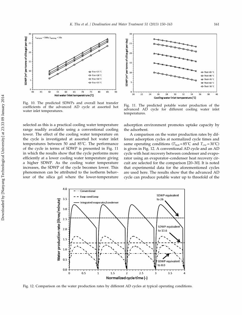
selected as this is a practical cooling water temperaturerange readily available using a conventional coolingtower. The effect of the cooling water temperature onthe cycle is investigated at assorted hot water inlettemperatures between 50 and 85˚C. The performanceof the cycle in terms of SDWP is presented in Fig. 11in which the results show that the cycle performs moreefficiently at a lower cooling water temperature givinga higher SDWP. As the cooling water temperatureincreases, the SDWP of the cycle becomes lower. Thisphenomenon can be attributed to the isotherm behav-iour of the silica gel where the lower-temperature
adsorption environment promotes uptake capacity bythe adsorbent.
A comparison on the water production rates by dif-ferent adsorption cycles at normalized cycle times andsame operating conditions (Thot = 85˚C and Tcw = 30˚C)is given in Fig. 12. A conventional AD cycle and an ADcycle with heat recovery between condenser and evapo-rator using an evaporator–condenser heat recovery cir-cuit are selected for the comparison [20–30]. It is notedthat experimental data for the aforementioned cyclesare used here. The results show that the advanced ADcycle can produce potable water up to threefold of the
Fig. 10. The predicted SDWPs and overall heat transfercoefficients of the advanced AD cycle at assorted hotwater inlet temperatures.
Fig. 11. The predicted potable water production of theadvanced AD cycle for different cooling water inlettemperatures.
Fig. 12. Comparison on the water production rates by different AD cycles at typical operating conditions.
K. Thu et al. / Desalination and Water Treatment 51 (2013) 150–163 161
Dow
nloa
ded
by [
Nan
yang
Tec
hnol
ogic
al U
nive
rsity
] at
23:
33 0
9 Ja
nuar
y 20
14
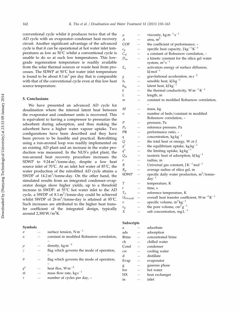
conventional cycle whilst it produces twice that of theAD cycle with an evaporator–condenser heat recoverycircuit. Another significant advantage of the advancedcycle is that it can be operational at hot water inlet tem-peratures as low as 50˚C whilst a conventional cycle isunable to do so at such low temperatures. This low-grade regeneration temperature is readily availablefrom the solar thermal sources or waste heat from pro-cesses. The SDWP at 50˚C hot water inlet temperatureis found to be about 8.1m3 per day that is comparablewith that of the conventional cycle even at this low heatsource temperature.
5. Conclusions
We have presented an advanced AD cycle fordesalination where the internal latent heat betweenthe evaporator and condenser units is recovered. Thisis equivalent to having a compressor to pressurize theadsorbent during adsorption, and thus making theadsorbent have a higher water vapour uptake. Twoconfigurations have been described and they havebeen proven to be feasible and practical. Retrofittingusing a run-around loop was readily implemented onan existing AD plant and an increase in the water pro-duction was measured. In the NUS’s pilot plant, therun-around heat recovery procedure increases theSDWP to 9.24m3/tonne-day, despite a low heatsource inlet of 70˚C. At an inlet hot water of 85˚C, thewater production of the retrofitted AD cycle attains aSWDP of 14.2m3/tonne-day. On the other hand, thesimulated results from an integrated condenser–evap-orator design show higher yields, up to a threefoldincrease in SWDP: at 55˚C hot water inlet to the ADcycle, a SWDP of 8.1m3/tonne-day could be achievedwhilst SWDP of 26m3/tonne-day is attained at 85˚C.Such increases are attributed to the higher heat trans-fer coefficient of the integrated design, typicallyaround 2,300W/m2K.
Symbols
r –– surface tension, Nm�1
a –– constant in modified Rohsenow correlation,–
q –– density, kgm�3
c –– flag which governs the mode of operation,–
h –– flag which governs the mode of operation,–
q00 –– heat flux, Wm�2
_m –– mass flow rate, kg s�1
s –– number of cycles per day, –
l –– viscosity, kgm�1 s�1
A –– area, m2
COP –– the coefficient of performance, –
cp –– specific heat capacity, J kg�1K�1
Csf –– a constant of Rohsenow correlation, –
Dso –– a kinetic constant for the silica gel watersystem, m2 s�1
Ea –– activation energy of surface diffusion,kJmol�1
g –– gravitational acceleration, m s�2
hf –– sensible heat, kJ kg�1
hfg –– latent heat, kJ kg�1
k –– the thermal conductivity, Wm�1 K�1
L –– length, m
m –– constant in modified Rohsenow correlation,–
M –– mass, kg
n –– number of beds/constant in modifiedRohsenow correlation, –
P –– pressure, Pa
P0 –– reference pressure, Pa
PR –– performance ratio, –
q –– concentration, kg kg�1
Q –– the total heat or energy, W or J
q⁄ –– the equilibrium uptake, kg kg�1
qo –– the limiting uptake, kg kg�1
Qst –– isosteric heat of adsorption, kJ kg�1
r –– radius, m
R –– Universal gas constant, J K�1mol�1
Rp –– average radius of silica gel, m
SDWP –– specific daily water production, m3/tonne-day�1
T –– temperature, K
t –– time, s
T0 –– reference temperature, K
UOverall –– overall heat transfer coefficient, Wm�2K�1
v –– specific volume, m3 kg�1
vp –– the pore volume, cm3 g�1
X –– salt concentration, mgL�1
Subscripts
a –– adsorbate
ads –– adsorption
Brine –– concentrated brine
ch –– chilled water
Cond –– condenser
cw –– cooling water
d –– distillate
Evap –– evaporator
g –– gaseous phase
hw –– hot water
HX –– heat exchanger
in –– inlet
162 K. Thu et al. / Desalination and Water Treatment 51 (2013) 150–163
Dow
nloa
ded
by [
Nan
yang
Tec
hnol
ogic
al U
nive
rsity
] at
23:
33 0
9 Ja
nuar
y 20
14
References[1] http://www.un.org/waterforlifedecade/background.shtml[2] http://www.2030waterresourcesgroup.com/water_full/[3] Jim S. Wallace, Peter J. Gregory, Water resources and their
use in food production systems, Aquatic Science 64 (2002)363–375.
[4] P. Pinstrup-Andersen, R. Pandya-Lorch, M.W. Rosegrant,The World Food Situation: Recent Developments, EmergingIssues, and Long-term Prospects, IFPRI, Washington, DC,1997.
[5] V. Frenkel, Desalination methods, technology and economics,in: Desalination Conference, Santa Barbara, CA, April 16,2004.
[6] http://webworld.unesco.org/water/ihp/db/shiklomanov/summary/html/summary.html#5.%20Water
[7] Semih Otles., Serkan Otles, Desalination techniques, Elec-tronic journal of Environmental, Agricultural and FoodChemistry 4 (2004) 963–969.
[8] Paul Alois, Global water crisis overview. Available from:http://www.arlingtoninstitute.org/wbp/global-water-crisis/441#, 2007.
[9] GWI DesalData/IDA, 21st GWI/International DesalinationAssociation Worldwide Desalting Plant Inventory, Desalina-tion in 2008, Global Market snapshot (2008).
[10] Lisa Henthorne, The current state of desalination. Availablefrom: http://www.idadesal.org/PDF/the%20current%20state%20of%20desalination%20remarks%20nov%2009%20by%20lisa%20henthorne.pdf.
[11] M.A. Darwish, N.M. Al-Najem, Energy consumption bymulti-stage flash and reverse osmosis desalters, AppliedThermal Engineering 20 (2000) 399–416.
[12] Masahiro Murakami, Managing Water for Peace in the Mid-dle East: Alternative Strategies, United Nations University,Tokyo, 1995.
[13] K.S. Spiegler, Y.M. El-Sayed, A desalination primer, Bal-aban Desalination, Santa Maria Imbaro, 1994.
[14] O.K. Buros, The ABCs of desalting, second ed., InternationalDesalination Association, Topsfield, MA, 2000.
[15] James E. Miller, Review of Water Resources and DesalinationTechnologies, http://prod.sandia.gov/techlib/access-control.cgi/2003/030800.pdf, 2003.
[16] John MacHarg., Thomas F. Seacord, Bradley sessions, ADCbaseline tests reveal trends in membrane performance, Desali-nation & Water Reuse 18 (2008) 30–39.
[17] M. A1-Shammiri, M. A1-Dawas, Maximum recovery fromseawater reverse osmosis plants in Kuwait, Desalination 110(1997) 37–48.
[18] Nikolay Voutchkov, Advances in seawater desalination tech-nology, Water Conditioning & Purification Magazine 49(2007) http://www.wcponline.com/pdf/0709Voutchkov.pdf.
[19] Kim Choon Ng., Bidyut Baran Saha, Anutosh Chakraborty,Shigeru Koyama, Adsorption desalination quenches globalthirst, Heat Transfer Engineering 29 (2008) 845–848.
[20] X. Wang, K.C. Ng, Experimental investigation of an adsorp-tion desalination plant using low-temperature waste heat,Applied Thermal Engineering 25 (2005) 2780–2789.
[21] K.C. Ng, X.L. Wang, L.Z. Gao, A. Chakraborty, B.B. Saha, S.Koyama, Apparatus and method for desalination, SG Patentapplication number 200503029-1 (2005) and WO Patent no.121414A1 (2006).
[22] K.C. Ng, H.T. Chua, C.Y. Chung, C.H. Loke, T. Kashiwagi, A.Akisawa, B.B. Saha, Experimental investigation of the silicagel–water adsorption isotherm characteristics, Applied Ther-mal Engineering 21 (2001) 1631–1642.
[23] A. Chakraborty, B.B. Saha, S. Koyama, K.C. Ng, Specific heatcapacity of a single component adsorbent-adsorbate system,Applied Physics Letters 98 (2011) 221910, doi: 10.1063/1.3592260.
[24] Chi Tien, Adsorption calculations and modeling, Elsevier Sci-ence & Technology Books, Boston, 1994.
[25] B.B. Saha, T. Kashiwagi, Experimental investigation of anadvanced adsorption refrigeration cycle, ASHRAE Transac-tions 103 (1997) 50–58.
[26] Kim Choon Ng, Anutosh Chakraborty, Sai Maung Aye, WangXiaolin, New pool boiling data for water with copper-foammetal at sub-atmospheric pressures: Experiments and correla-tion, Applied Thermal Engineering 26 (2006) 1286–1290.
[27] Kyaw Thu, K.C. Ng, B.B. Saha, A. Chakraborty, Overall ofheat transfer analyses of a heat-driven adsorption chiller atassorted regeneration temperatures, in: International Sympo-sium on Next-generation Air Conditioning and RefrigerationTechnology, Tokyo, Japan, February 17–19, 2010.
[28] Kyaw Thu, Bidyut Baran Saha, Anutosh Chakraborty, WonGee Chun, Kim Choon Ng, Study on an advanced adsorptiondesalination cycle with evaporator–condenser heat recoverycircuit, International Journal of Heat and Mass Transfer 54(2011) 43–51.
[29] K. Thu, K.C. Ng, B.B. Saha, A. Chakraborty, S. Koyama,Operational strategy of adsorption desalination system, Inter-national Journal of Heat and Mass Transfer 52 (2009)1811–1816.
[30] Kim Choon Ng, Kyaw Thu, Hideharu Yanagi, Anutosh Cha-kraborty, Bidyut B. Saha, Performance analysis of a low tem-perature waste heat-driven adsorption desalination prototypeplant, in: The 5th Asian Conference on Refrigeration and Air-conditioning, Tokyo, Japan, June 7–9, 2010.
l –– liquid
des –– desorption
out –– outlet
reg –– regeneration
s –– salt/adsorbent
sg –– silica gel
ss –– stainless steel
v –– vapour
w –– wall
K. Thu et al. / Desalination and Water Treatment 51 (2013) 150–163 163
Dow
nloa
ded
by [
Nan
yang
Tec
hnol
ogic
al U
nive
rsity
] at
23:
33 0
9 Ja
nuar
y 20
14


![-A-iodp.tamu.edu/publications/resources/IODP_dictionary.pdf · IODP Dictionary 2 adnVISION [logging] adsorption advanced circulation obviation retrofit kit ACORK advanced diamond](https://static.fdocuments.net/doc/165x107/5e0d326b80ba053f616eb3dc/a-iodptamuedupublicationsresourcesiodp-iodp-dictionary-2-adnvision-logging.jpg)