Performance Evaluation of Mobile Video Delivery Technologies · Performance Evaluation of Mobile...
94
Diplomarbeit Performance Evaluation of Mobile Video Delivery Technologies ausgef¨ uhrt zum Zwecke der Erlangung des akademischen Grades eines Diplom-Ingenieurs unter Leitung von Betreuer: Michal Ries Professor: Markus Rupp E389 Institut f¨ ur Nachrichtentechnik und Hochfrequenztechnik eingereicht an der Technischen Universit¨ at Wien Fakult¨ at f¨ ur Elektrotechnik und Informationstechnik von Jan Gero Matrikelnummer: 0526970 Wien, im September 2007
Transcript of Performance Evaluation of Mobile Video Delivery Technologies · Performance Evaluation of Mobile...
Diplomarbeit
Performance Evaluation of
Mobile Video Delivery
Technologies
ausgefuhrt zum Zwecke der Erlangung des akademischen Grades einesDiplom-Ingenieurs unter Leitung von
Betreuer: Michal RiesProfessor: Markus Rupp
E389Institut fur Nachrichtentechnik und Hochfrequenztechnik
eingereicht an der Technischen Universitat WienFakultat fur Elektrotechnik und Informationstechnik
von
Jan GeroMatrikelnummer: 0526970
Wien, im September 2007
Contents
Abstract iv
List of Abbreviations v
List of Figures ix
List of Tables x
1 Introduction 1
1.1 Motivation . . . . . . . . . . . . . . . . . . . . . . . . . . . . . . 3
1.2 Outline of the thesis . . . . . . . . . . . . . . . . . . . . . . . . 4
2 High Speed Downlink Packet Access 6
2.1 Historical overview . . . . . . . . . . . . . . . . . . . . . . . . . 6
2.1.1 3GPP releases . . . . . . . . . . . . . . . . . . . . . . . . 7
2.1.2 Release 99 - UMTS . . . . . . . . . . . . . . . . . . . . . 7
2.2 HSDPA enhancements . . . . . . . . . . . . . . . . . . . . . . . 10
2.2.1 General Channel Structure . . . . . . . . . . . . . . . . . 10
2.2.2 Adaptive Modulation and Coding . . . . . . . . . . . . . 13
2.2.3 Hybrid ARQ . . . . . . . . . . . . . . . . . . . . . . . . 14
2.2.4 Fast scheduling . . . . . . . . . . . . . . . . . . . . . . . 15
2.3 Additional notes . . . . . . . . . . . . . . . . . . . . . . . . . . 16
3 Digital Video Broadcasting - Handheld 17
3.1 Introduction to DVB-H . . . . . . . . . . . . . . . . . . . . . . . 17
i
CONTENTS ii
3.1.1 Requirements . . . . . . . . . . . . . . . . . . . . . . . . 18
3.1.2 Overview of the System . . . . . . . . . . . . . . . . . . 19
3.2 Innovations in the physical layer . . . . . . . . . . . . . . . . . . 21
3.2.1 Signaling in the TPS-bits . . . . . . . . . . . . . . . . . . 21
3.2.2 OFDM transmission modes . . . . . . . . . . . . . . . . 22
3.2.3 In-depth interleaver . . . . . . . . . . . . . . . . . . . . . 23
3.3 Link Layer . . . . . . . . . . . . . . . . . . . . . . . . . . . . . . 24
3.3.1 Time Slicing . . . . . . . . . . . . . . . . . . . . . . . . . 24
3.3.2 MPE - FEC . . . . . . . . . . . . . . . . . . . . . . . . . 29
3.4 Remaining issues about DVB-H . . . . . . . . . . . . . . . . . . 33
3.4.1 Interactivity . . . . . . . . . . . . . . . . . . . . . . . . . 33
3.4.2 DVB-H network . . . . . . . . . . . . . . . . . . . . . . . 34
3.4.3 Standardization . . . . . . . . . . . . . . . . . . . . . . . 36
4 HSDPA measurements 37
4.1 Scenarios . . . . . . . . . . . . . . . . . . . . . . . . . . . . . . . 38
4.1.1 Indoor scenario . . . . . . . . . . . . . . . . . . . . . . . 38
4.1.2 Tram scenario . . . . . . . . . . . . . . . . . . . . . . . . 39
4.1.3 Pedestrian . . . . . . . . . . . . . . . . . . . . . . . . . . 40
4.2 Video Content . . . . . . . . . . . . . . . . . . . . . . . . . . . . 41
4.3 Tools . . . . . . . . . . . . . . . . . . . . . . . . . . . . . . . . . 42
4.4 Methodology . . . . . . . . . . . . . . . . . . . . . . . . . . . . 44
4.4.1 Set-up of video sequences . . . . . . . . . . . . . . . . . 45
4.4.2 Streaming server setup . . . . . . . . . . . . . . . . . . . 46
4.4.3 Streaming and recording . . . . . . . . . . . . . . . . . . 47
4.4.4 Packet analyses . . . . . . . . . . . . . . . . . . . . . . . 47
4.4.5 Video processing and calculations . . . . . . . . . . . . . 47
4.5 Results . . . . . . . . . . . . . . . . . . . . . . . . . . . . . . . . 48
4.5.1 QuickTime vs. VLC . . . . . . . . . . . . . . . . . . . . 48
4.5.2 Network analyses . . . . . . . . . . . . . . . . . . . . . . 50

CONTENTS iii
4.5.3 PSNR analyses . . . . . . . . . . . . . . . . . . . . . . . 53
4.5.4 Overall results . . . . . . . . . . . . . . . . . . . . . . . . 58
5 DVB-H measurements 60
5.1 Scenarios . . . . . . . . . . . . . . . . . . . . . . . . . . . . . . . 61
5.2 Video Content . . . . . . . . . . . . . . . . . . . . . . . . . . . . 62
5.3 Tools . . . . . . . . . . . . . . . . . . . . . . . . . . . . . . . . . 63
5.4 Methodology . . . . . . . . . . . . . . . . . . . . . . . . . . . . 63
5.4.1 Enabling DVB-H services on DVB-T receiver . . . . . . . 63
5.4.2 Receiving and recording . . . . . . . . . . . . . . . . . . 63
5.4.3 Capturing . . . . . . . . . . . . . . . . . . . . . . . . . . 64
5.4.4 Video processing and calculations . . . . . . . . . . . . . 64
5.5 Results . . . . . . . . . . . . . . . . . . . . . . . . . . . . . . . . 65
5.5.1 Difficulties . . . . . . . . . . . . . . . . . . . . . . . . . . 65
5.5.2 PSNR analyses . . . . . . . . . . . . . . . . . . . . . . . 67
6 Conclusions 69
Appendix 72
Bibliography 76

Abstract
The aim of this diploma thesis was to evaluate the performance of the state-of-
the-art mobile video delivery technologies. For this purpose two technologies,
HSDPA and DVB-H, were chosen. The performance parameters for ”high qual-
ity” streaming were investigated and all measurements were provided in live
network.
A video service over HSDPA is an On Demand approach, which means that
users are requesting any media at any time they want. DVB-H is a broadcasting
approach like standard TV usage scenario, where all users are receiving the same
media at the same time.
Using these technologies, video sequences were recorded in several situations
- scenarios. Additionally, streaming of the most promising video content types
was investigated. An objective video quality metric PSNR was used to compute
the quality of received video streams at the application layer of the OSI model.
Moreover measurements at the network layer were provided.
In the HSDPA case a streaming server was used to provide these measure-
ments. However, this was not possible in DVB-H case, where we did not get
access to the content provider. Therefore an alternative solution was chosen.
This thesis proves the ability of mentioned technologies to provide high qual-
ity video services.
iv
List of Abbreviations
2G Second Generation
3G Third Generation
3GPP Third Generation Partnership Project
ADT Application Data Table
AMC Adaptive Modulation and Coding
ARIB Association of Radio Industries and Businesses
ARQ Automatic Repeat Request
ATIS Alliance for Telecommunications Industry Solutions
AVI Audio Video Interleave
C/I Carrier to Interference
CC Chase Combining
CCSA China Communications Standards Association
CDMA Code Division Multiple Access
CDP Content Delivery Protocols
CN Core Network
CQI Channel Quality Indicator
CRC Cyclic Redundancy Check
CS Circuit Switched
DMB Digital Multimedia Broadcasting
DSCH Downlink Shared Channel
DSS Darwin Streaming Server
DVB Digital Video Broadcasting
DVB-H Digital Video Broadcasting-Handheld
DVB-T Digital Video Broadcasting-Terrestrial
EDGE Enhanced Data rates for GSM Evolution
v

vi
ES Elementary Stream
ESG Electronic Service Guide
ETSI European Telecommunications Standards Institute
FEC Forward Error Correction
FFT Fast Fourier Transformation
Fig. Figure
FPS Frames per Second
GERAN GSM/EDGE Radio Acces Network
GPRS General Packet Radio Service
HARQ Hybrid Automatic Repeat Request
HS-DPCCH High-Speed Dedicated Physical Control Channel
HS-DSCH High-Speed Downlink Shared Channel
HS-SCCH High-Speed Shared Control Channel
HSDPA High Speed Downlink Packet Access
HSUPA High Speed Uplink Packet Access
IEEE Institute of Electrical and Electronics Engineers
IMS IP Multimedia System
IMT - 2000 International Mobile Telecommunications - 2000
IP Internet Protocol
IR Incremental Redundancy
ISDB Integrated Services Digital Broadcasting
ITU International Telecommunication Union
LTE Long Term Evolution
MAC-hs Media Access Control high speed
MBMS Multimedia Broadcast Multicast Service
MCS Modulation and Coding Schemes
MediaFLO Forward Link Only
MPE Multi-Protocol Encapsulation
MPE-FEC Multi-Protocol Encapsulation Forward Error Correction

vii
MPEG Motion Picture Experts Group
OFDM Orthogonal Frequency Division Multiplex
PC Personal Computer
PCM/CIA Personal Computer Memory / Card International Association
PDA Personal Digital Assistent
PDF Probability Density Function
PID Program Identifier
PS Packet Switched
PSI/SI Program Specific Information/Service Information
PSNR Peak Signal to Noise Ratio
QAM Quadrature Amplitude Modulation
QoS Quality of Service
QPSK Quadrature Phase-Shift Keying
QT QuickTime
RAN Radio Acces Network
RF Radio Frequency
RNC Radio Network Controller
RS Reed Solomon (code)
RTP Real-time Transport Protocol
RTCP Real-time Transport Control Protocol
RTSP Real Time Streaming Protocol
SAW Stop and Wait
SDP Session Description Protocol
SF Spreading Factor
SI Service Information
SNR Signal to Nosie Ratio
SPP Service Purchase and Protection
SSH Secure Shell
TD-CDMA Time Division - Code Division Multiple Access

TDM Time Division Multiplex
TDtv Time Division TV
TPS Transmission-Parameter Signaling
TS Transport Stream
TTA Telecommunication Technology Association
TTC Telecommunication Technology Committee
TTI Transmission Time Interval
UE User Equipment
UHF Ultra High Frequency
UMTS Universal Mobile Telecommunications System
UTRAN UMTS Terrestrial Radio Acces Network
VHF Very High Frequency
W-CDMA Wideband Code Division Multiple Access
WLAN Wireless Local Area Network
viii
List of Figures
1.1 Video Broadcasting and Video On Demand scenarios . . . . . . 3
2.1 UMTS Radio Access Network . . . . . . . . . . . . . . . . . . . 9
2.2 The code and time structure of HS-DSCH [Park Eng] . . . . . . 11
2.3 New channels in HSDPA [Qualcomm] . . . . . . . . . . . . . . . 12
3.1 DVB-H System, including added new features [FactSheet 07] . . 20
3.2 In-depth symbol interleaving [Kornfeld 05] . . . . . . . . . . . . 23
3.3 Conceptual structure of DVB-H receiver [EN 302 304] . . . . . . 24
3.4 Continual transmission structure [Kangas 06] . . . . . . . . . . . 25
3.5 Time slicing structure [Kangas 06] . . . . . . . . . . . . . . . . . 26
3.6 DVB-H and DVB-T services [Henriksson 05] . . . . . . . . . . . 26
3.7 Delta-T method [EN 301 192] . . . . . . . . . . . . . . . . . . . 27
3.8 Burst parameters [EN 301 192] . . . . . . . . . . . . . . . . . . 28
3.9 Protocol stack of DVB-H [Sams] . . . . . . . . . . . . . . . . . . 29
3.10 Different stages of error protection in an DVB-H transmitter
block [Kornf Perf 06] . . . . . . . . . . . . . . . . . . . . . . . . 30
3.11 MPE-FEC frame [Lopez 06] . . . . . . . . . . . . . . . . . . . . 31
3.12 MPE-FEC frame structure containing data [Balaguer] . . . . . . 33
3.13 Interactivity as proposed by Nokia [Nok Inter] . . . . . . . . . . 34
3.14 The family of DVB-H standards . . . . . . . . . . . . . . . . . . 36
4.1 Indoor scenario location and the corresponding base station . . 39
4.2 Average HSDPA traffic in time during the Indoor measurements 39
ix
x
4.3 The measurement route of the Tram scenario . . . . . . . . . . . 40
4.4 Pedestrian scenario location and the corresponding base station 41
4.5 Average HSDPA traffic in time during the Pedestrian measurements 42
4.6 Video content . . . . . . . . . . . . . . . . . . . . . . . . . . . . 42
4.7 QT and VLC comparison of the data packet flow - Football . . . 49
4.8 QT and VLC comparison of the data packet flow - News . . . . 50
4.9 QT and VLC comparison of the data packet flow - Music . . . . 51
4.10 Example of PSNR graph for soccer in the Indoor scenario . . . . 53
4.11 PDF of Football in Indoor scenario for QuickTime and VLC . . 55
4.12 PDF of News in Indoor scenario for QuickTime and VLC . . . . 55
4.13 PDF of Music in Indoor scenario for QuickTime and VLC . . . 55
4.14 PDF of Football in Tram scenario for QuickTime and VLC . . . 56
4.15 PDF of News in Tram scenario for QuickTime and VLC . . . . 56
4.16 PDF of Music in Tram scenario for QuickTime and VLC . . . . 56
4.17 PDF of Football in Pedestrian scenario for QuickTime and VLC 57
4.18 PDF of News in Pedestrian scenario for QuickTime and VLC . . 57
4.19 PDF of Music in Pedestrian scenario for QuickTime and VLC . 57
5.1 Locations of the DVB-H scenarios . . . . . . . . . . . . . . . . . 62
5.2 The difference between coding formats of DVB-T and DVB-H . 66
5.3 The color shade of DVB-T and DVB-H video . . . . . . . . . . 67
5.4 PSNR between the first 1000 frames of the pedestrian scenario . 68
List of Tables
1.1 The attributes of standard TV and mobile TV [Rhode] . . . . . 2
1.2 Overview of mobile technologies providing TV services . . . . . 4
3.1 Signal parameters for possible DVB-H OFDM transmission modes
[Kornfeld 05] . . . . . . . . . . . . . . . . . . . . . . . . . . . . 22
4.1 Video content . . . . . . . . . . . . . . . . . . . . . . . . . . . . 46
4.2 Packet analyses when streaming through VLC . . . . . . . . . . 51
4.3 Packet analyses when streaming through QT . . . . . . . . . . . 52
4.4 PSNR values for all scenarios . . . . . . . . . . . . . . . . . . . 58
xi

Chapter 1
INTRODUCTION
The idea of communication was always understood as a process that allows
people to exchange thoughts by one of several methods. By the means of tech-
nical progress, these methods came to a higher level. The main communication
drivers nowadays are television and mobile communication.
Television became commercially available in the 1930s [TVhist]. Since then it
captured people all over the world and became the biggest media. However,
probably the highest qualitative step was made in recent years by introducing
digital broadcasting. It was supported by former deployment of digital tech-
nologies like personal video recorders, DVD technology and video streaming
technologies over internet. These triggered enormous interest of consumers.
Mobile communication itself is an extension of the basic telecommunication
service - telephony, which started already at the end of nineteenth century.
Worldwide employment of mobile services began in the 1990s. The step into a
new millennium was also a step to another generation of mobile communication
technology. Third Generation (3G) networks provide new services and features,
where the most significant are higher capacity and data rates.
The rapid evolution in these two environments and huge user demand of both,
leads to a logical ambition of merging them into new types of services - mobile
1

Chapter 1 - INTRODUCTION 2
video services. As a matter of course, this carries some new challenges which
can be approached from the side of either of the communication drivers.
• From the digital broadcasting (TV) point of view; broadcasters were used
to bring TV services to home. Their TV receivers have generally great
screen resolution and are supplied directly from mains. This will not
be the case if they would like to broadcast to mobile handsets, because
these equipments have generally small screens, limited battery and are in
motion. The difference is shown in the Table 1.1.
Table 1.1: The attributes of standard TV and mobile TV [Rhode]
• From the point of view of mobile communications ; service operators are
well experienced in issues related to mobile environment. However they
were used to offer their services to single users, called unicast. Broadcast
services, how we understand them by means of television is the great
challenge for this approach [Alcat 06].
There is also another way to look at the growing inquiry for mobile video ser-
vices. Looking from the providing perspective (the way of distributing the
service), there are basically two approaches. One is called Video Broadcasting
Chapter 1 - INTRODUCTION 3
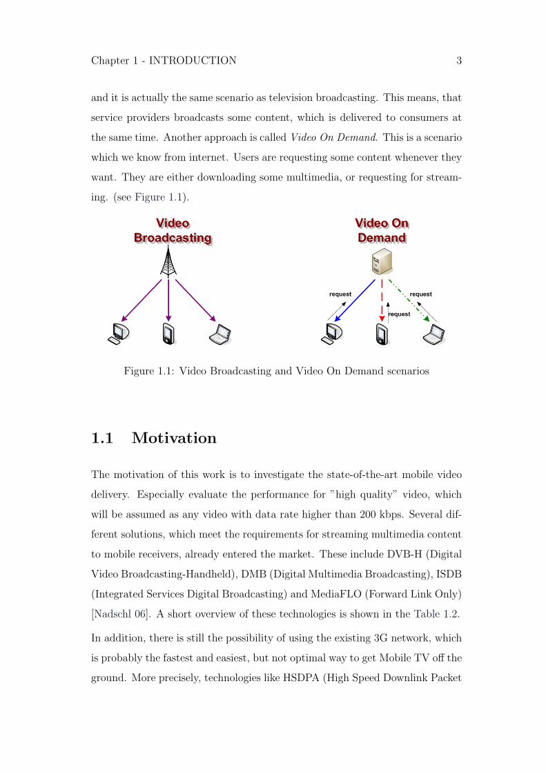
and it is actually the same scenario as television broadcasting. This means, that
service providers broadcasts some content, which is delivered to consumers at
the same time. Another approach is called Video On Demand. This is a scenario
which we know from internet. Users are requesting some content whenever they
want. They are either downloading some multimedia, or requesting for stream-
ing. (see Figure 1.1).
Figure 1.1: Video Broadcasting and Video On Demand scenarios
1.1 Motivation
The motivation of this work is to investigate the state-of-the-art mobile video
delivery. Especially evaluate the performance for ”high quality” video, which
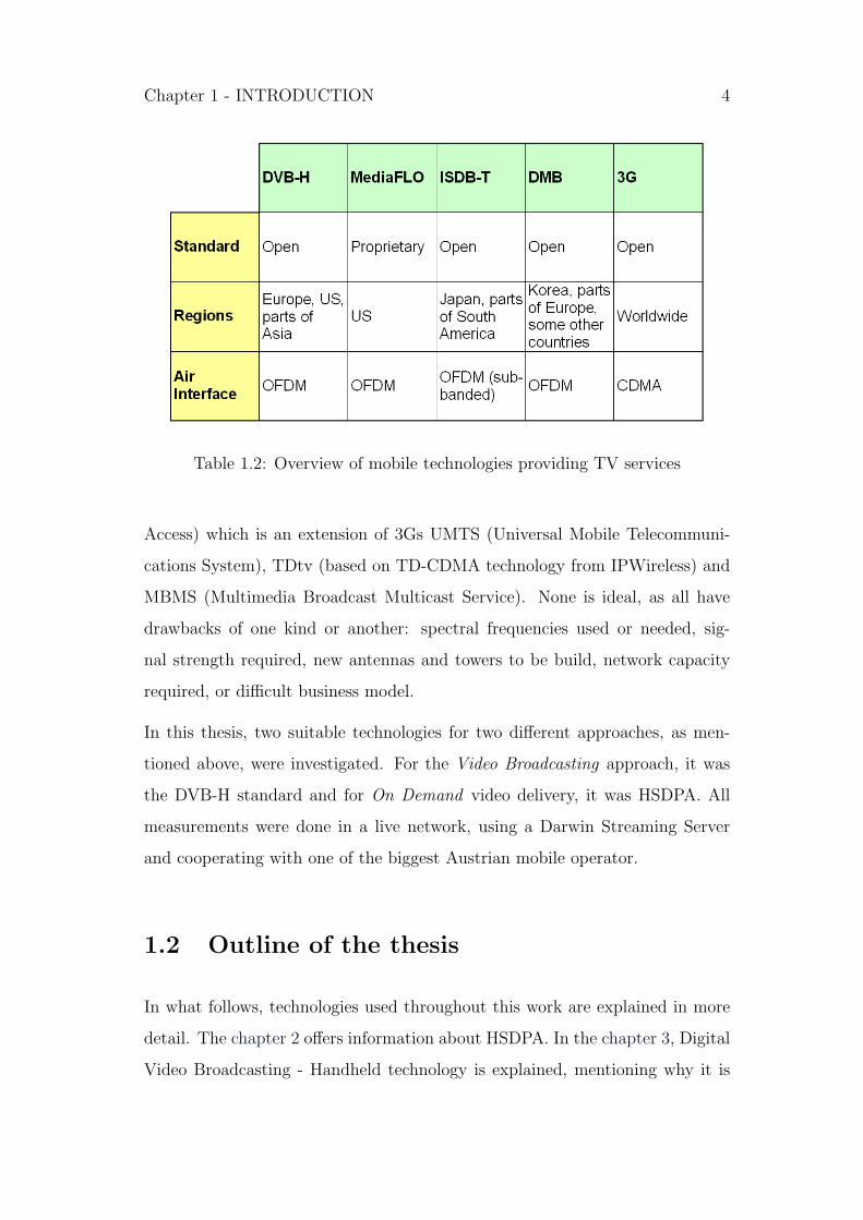
will be assumed as any video with data rate higher than 200 kbps. Several dif-
ferent solutions, which meet the requirements for streaming multimedia content
to mobile receivers, already entered the market. These include DVB-H (Digital
Video Broadcasting-Handheld), DMB (Digital Multimedia Broadcasting), ISDB
(Integrated Services Digital Broadcasting) and MediaFLO (Forward Link Only)
[Nadschl 06]. A short overview of these technologies is shown in the Table 1.2.
In addition, there is still the possibility of using the existing 3G network, which
is probably the fastest and easiest, but not optimal way to get Mobile TV off the
ground. More precisely, technologies like HSDPA (High Speed Downlink Packet
Chapter 1 - INTRODUCTION 4
Table 1.2: Overview of mobile technologies providing TV services
Access) which is an extension of 3Gs UMTS (Universal Mobile Telecommuni-
cations System), TDtv (based on TD-CDMA technology from IPWireless) and
MBMS (Multimedia Broadcast Multicast Service). None is ideal, as all have
drawbacks of one kind or another: spectral frequencies used or needed, sig-
nal strength required, new antennas and towers to be build, network capacity
required, or difficult business model.
In this thesis, two suitable technologies for two different approaches, as men-
tioned above, were investigated. For the Video Broadcasting approach, it was
the DVB-H standard and for On Demand video delivery, it was HSDPA. All
measurements were done in a live network, using a Darwin Streaming Server
and cooperating with one of the biggest Austrian mobile operator.
1.2 Outline of the thesis
In what follows, technologies used throughout this work are explained in more
detail. The chapter 2 offers information about HSDPA. In the chapter 3, Digital
Video Broadcasting - Handheld technology is explained, mentioning why it is

Chapter 1 - INTRODUCTION 5
appropriate for mobile environments. Subsequently, information about the test
bed, scenarios, measurements and results of HSDPA and DVB-H are presented
in chapter 4 and chapter 5 respectively. Finally, in the chapter 6 this work ends
with some conclusions.

Chapter 2
HIGH SPEED DOWNLINK
PACKET ACCESS
2.1 Historical overview
Mobile telephony systems are undergoing a rapid evolution in recent years.
Nowadays the very successful 2G (Second Generation) technology GSM (Global
System for Mobile communication), is being altered by its 3G successor, called
UMTS (Universal Mobile Telecommunications System).
While the 2G made a giant step from analog networks to digital, the key fea-
tures of 3G are increased capacity of customers, as well as significantly higher
data rates. This opens a variety of new service opportunities, including video
telephony or mobile TV. 3G can be based on different underlying radio air in-
terfaces, which are basically related to CDMA (Code Division Multiple Access).
Currently, the most common mobile phone technology, UMTS, is based on the
use of W-CDMA (Wideband Code Division Multiple Access).
6

Chapter 2 - HSDPA 7
2.1.1 3GPP releases
UMTS was standardized by the 3GPP (3rd Generation Partnership Project),
which is a collaboration agreement established in December 1998. It is an inter-
national co-operation between European ETSI, Japanese ARIB/TTC, Chinese
CCSA, North American ATIS and South Korean TTA1 [3GPP]. The great num-
bers of 3GPP standards are structured in a so-called Release, which introduces
new features. Up to now releases are:
Release 98 - specifies pre-3G GSM networks
Release 99 - specifies the UMTS 3G networks [Summary 99]
Release 4 - adds features including an all-IP Core Network
[Summary 04]
Release 5 - introduces HSDPA and IMS (IP Multimedia System)
[Summary 05]
Release 6 - introduces WLAN (Wireless Local Area Network)
integration, HSUPA (High Speed Uplink Packet Access),
MBMS (Multimedia Broadcast Multicast Service)
and some other features [Summary 06]
Release 7 - (in progress) focuses on QoS improvements and decreasing
latency and other features
Plans for the future beyond Release 7 are developed under the title Long Term
Evolution (LTE). One of the main objectives of this research is to enable an
all-IP network [Am Rel 7].
2.1.2 Release 99 - UMTS
Every 3GPP release is in some way a milestone in the 3G development, but
Realease 99 is one of special importance. It meets the original scope of 3GPP,
1For convenience are the shortcuts explained only in the List of Abbreviations

Chapter 2 - HSDPA 8
to produce globally applicable 3G mobile phone system, which would fulfill the
IMT-20002 requirements [Wireless]:
• better spectral efficiency;
• higher peak data rates - up to 2Mbit/s - which would result in a choice
of channels with a bandwidth of 5MHz instead of 200kHz indoor and
384kbit/s outdoor of GSM;
• supporting multimedia applications, meaning the retransmission of voice,
arbitrary data, text, pictures, audio and video, which requires increased
flexibility in the choice of data rates;
• backwards compatibility to second-generation systems;
Release 99 (UMTS) is a very mature specification, providing an evolution path
for the GSM network and especially for its improvements GPRS (General Packet
Radio Service) and EDGE (Enhanced Data rates for GSM Evolution) [Am Evol 04].
The architecture of UMTS in whole is composed of three subsystems:
• radio access network (RAN)
• circuit switched (CS) core network (CN)
• packet switched (PS) core network.
To ensure the backward compatibility, access network of the new system con-
sists of two main components: GSM/EDGE radio access network (GERAN)
and UMTS terrestrial radio access network (UTRAN) [Hakaste]. UTRAN ar-
chitecture is depicted on the Figure 2.1.
UMTS is nowadays commercial deployed in many countries all over the world,
provided by hundreds of mobile operators and having more than 30 million
2International Mobile Telecommunications - 2000 is the global standard for 3G as defined
by International Telecommunication Union (ITU).

Chapter 2 - HSDPA 9
Figure 2.1: UMTS Radio Access Network
subscribers [UMTS Forum]. Data rates considerably exceed the speeds of GSM
and reach the limit of 384 kbps. However, these seem not to be enough for some
demanding services, like video and music on demand. Hence the potential of
3G had to be further exploited.
Introduction of the new Release 5 aimed to increase the spectral efficiency,
improve user experiences and add new services [Nort paper]. One of the key
feature of this release is High Speed Downlink Packet Access (HSDPA), which
offers much higher capacity and downlink data rates. HSDPA is being described
in the following sections.

Chapter 2 - HSDPA 10
2.2 HSDPA enhancements
HSDPA provides considerable improvements over Release 99 for the downlink,
achieved by employing of some new techniques. Possible peak data rates are
up to 14,4 Mbps and sector throughput is increased three- to five-fold, which
significantly raises the number of data users on a single frequency [Qualcomm].
Applying some small changes in the UTRAN translates into shorter connection
and response times.
Implemented methods like Adaptive Modulation and Coding (AMC), Hybrid
ARQ (Automatic Repeat Request), or Fast Scheduling, make this improvements
possible. Great advantage of HSDPA is also in the very cost effective deploy-
ment, since the incremental cost is mainly due to software/hardware upgrade
of the Node B and RNC (Radio Network Controller) [Qualcomm]. Mentioned
techniques are described in the following subsections.
2.2.1 General Channel Structure
One of the major innovations of HSDPA over Release 99 is the introduction of
three new channel types:
• High-Speed Downlink Shared Channel (HS-DSCH)
• High-Speed Shared Control Channel (HS-SCCH)
• High-Speed Dedicated Physical Control Channel (HS-DPCCH)
HS-DSCH
The HS-DSCH is a shared transport channel type very similar to the DSCH
in Release 99. As in case of DSCH, the channel is shared among all users in
some specific sector. However, while the scheduling in DSCH is done in the
RNC, scheduling in HS-DSCH is done closer to the user equipment, in the Node

Chapter 2 - HSDPA 11
B. The purpose of the new channel is to be the main radio bearer, offering a
best-effort packet data service and supporting the technologies discussed below
[Parkvall].
Since HSDPA is based on the CDMA technology, channels are divided by the
means of Spreading Factor (SF) codes. HS-DSCH is shared in a number of SF
16 codes. In addition it is shared in the time domain. The corresponding time
unit is called TTI (Transmission Time Interval). Its duration is fixed and equal
to 2 ms [TS 25.308]. Since HSDPA is a best-effort service, all codes can be
assigned to one user during the TTI, or may be divided between other users.
The corresponding code and time structure is shown on the Figure 2.2.
Figure 2.2: The code and time structure of HS-DSCH [Park Eng]
The TTI of 2 ms in HSDPA is significantly lower than the 20 ms, 40 ms, or 80 ms
in Release 99. The advantage of shorter TTI is in better short round trip delay
between the UE (User Equipment) and the Node B. Furthermore it improves
Chapter 2 - HSDPA 12
the link adaptation ability and is important for the Adaptive Modulation and
Coding (AMC) technique.
HS-DSCH is supported by two additional control channels described next.
HS-SCCH
The HS-SCCH is a control channel used for the downlink signaling between the
Node B and the UE. It is accompanied with each HS-DSCH before the beginning
of every TTI. Although it is a shared channel, it has a fixed rate of 60 kbps and
SF of 128 [Qualcomm]. It carries the information regarding when to receive the
HS-DSCH [Hiltunen]. The signaling message furthermore includes AMC and
HARQ (Hybrid ARQ) information [DSCH Design].
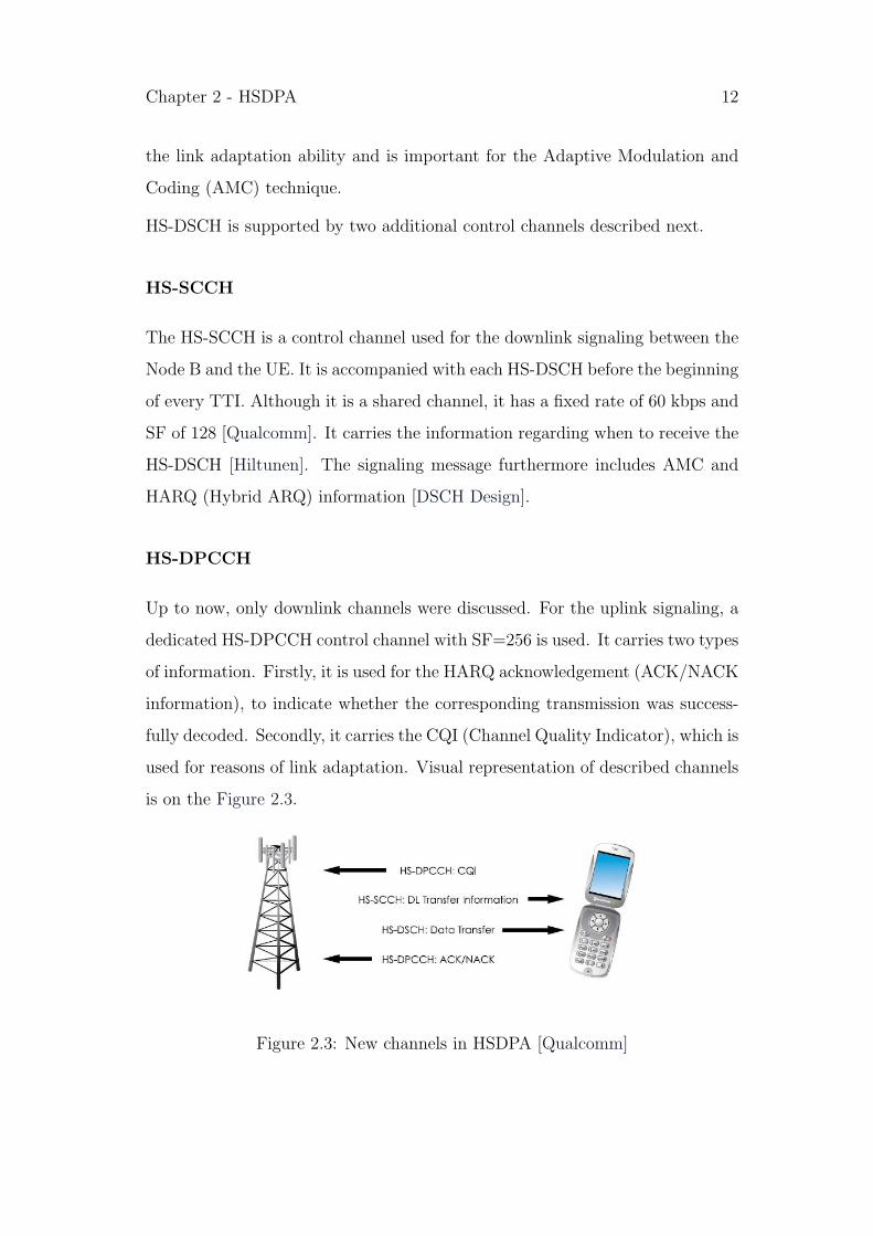
HS-DPCCH
Up to now, only downlink channels were discussed. For the uplink signaling, a
dedicated HS-DPCCH control channel with SF=256 is used. It carries two types
of information. Firstly, it is used for the HARQ acknowledgement (ACK/NACK
information), to indicate whether the corresponding transmission was success-
fully decoded. Secondly, it carries the CQI (Channel Quality Indicator), which is
used for reasons of link adaptation. Visual representation of described channels
is on the Figure 2.3.
Figure 2.3: New channels in HSDPA [Qualcomm]

Chapter 2 - HSDPA 13
2.2.2 Adaptive Modulation and Coding
One of the basic features of HSDPA is the AMC. The fundamental idea is to
dynamically change defined Modulation and Coding Schemes (MSC) [AMC 3G].
Each MSC consist of some parameters like code rate, modulation scheme, number
of codes, or transmit power [Dotlling]. The aim is to continuously optimize these
parameters to the actual channel conditions. The decision about choosing the
optimum MSC is performed according to the report received from the CQI and
can change every TTI.
Encoding
The encoding scheme used in HSDPA is based on the Release 99 rate (1/3 Turbo
encoder), but adds some new alternatives (1/4 to 3/4).
Modulation scheme
Another way to adapt to channel conditions is to change the modulation scheme.
High order modulations offer higher data rate, but at cost of the robustness.
Thus when targeting a higher level of reliability, e.g. being closer to Node B,
system can offer higher modulation. Lower modulation is then assigned, when
facing worse conditions, e.g. being at the end of a cell. HSDPA standards intro-
duce an additional 16QAM modulation to the existing QPSK used in Release
99.
Number of codes
User equipments in HSDPA can support different number of codes: five, ten, or
fifteen. Assigning more codes to one user, results in higher data rates. In the
very special case, with 16QAM modulation, 15 codes and with no coding (code
rate is one), user is able to achieve the maximum specified peak data rate of
14,4Mbps. However, this case is very unlikely in the reality.
Chapter 2 - HSDPA 14
Transmit power
The employment of AMC results in better utilization of the power of Node B.
2.2.3 Hybrid ARQ
Hybrid Automatic Repeat Request is another essential feature of HSDA. It
gives better performance than the ordinary ARQ error control method, which is
achieved by soft combining and using N-Channel Stop and Wait (SAW) protocol.
Retransmissions requests are sent in the case, when data is not correctly de-
coded. Otherwise, a positive acknowledgement is signaled through the uplink
dedicated physical channel [Parkvall]. The major gain of HARQ provides the
utilization of the erroneously received information. This is not discarded, but
combined together with retransmitted information, resulting in significantly im-
proved performance and robustness to link adaptation errors. The combining
of the retransmitted and erroneously transmitted soft information can be per-
formed in two main ways: Chase Combining (CC), or Incremental Redundancy
(IR).
• CC is the simpler way, requiring minimum complexity and buffer. The
retransmission is identical with the initial transmission, which was erro-
neously decoded.
• IR is a more complex scheme, requiring higher memory for the UE. In-
stead of sending simple repeats of the information, additional redundant
information is incrementally transmitted [HARQ].
Stop and Wait mechanism is used, to manage the retransmissions and acknowl-
edgements. In a single SAW protocol, the transmitter waits for an acknowledge-
ment after every sent information unit. However, there is a desire for better
exploitation of the waiting time between acknowledgements. For this purpose
N-channel SAW is used, whereby N different SAW protocols are working in
Chapter 2 - HSDPA 15
parallel. While one channel is waiting for the acknowledgement, the remaining
N-1 channels continue to transmit. There are up to six such channels used for
advanced Node B implementation [Qualcomm].
Another benefit of HARQ follows from the place of its implementation. It is
implemented at the MAC-hs (Media Access Control high speed) sub layer, which
is located at the Node B. On the other hand, the retransmission functionality
of Release 99 is implemented in the RNC. These outcomes with much lower
retransmission delay for HSDPA compared to Release 99.
2.2.4 Fast scheduling
As mentioned above, the HS-DSCH is a best-effort transmit channel, which is
shared among all users in a particular sector. Therefore, some part of the system
has to be responsible for the allocation of the channel resources among the users.
Fast Scheduler is the key element of HSDPA providing described functionality.
One of the advantages of scheduling in HSDPA over Release 99 is again in the
emplacement. As with the HARQ, also the scheduler is located in the Node B.
This leads to better performance and overall behavior of the whole system.
Scheduling method works in conjunction with AMC, choosing different sched-
ulers for different scenarios. Just as in the case of AMC, also the scheduler can
modify with each TTI. The chosen scheduler depends also on the CQI, which
provides the actual information about the channel. This enables the base station
to flexibly decide which terminal’s packets to send, considering the fairness and
throughput [Etoh]. Corresponding to them, there are several scheduling algo-
rithms. The most common are: Round Robin, Maximum Carrier to Interference
(C/I), and Proportional Fair.
• Round Robin is the easiest algorithm. The channel resources are equally
assigned to all communicating users [Ofuji]. Users are served regardless of
Chapter 2 - HSDPA 16
their signal quality. The outcome is a very high degree of fairness, but at
the cost of system throughput.
• On the other hand, the Maximum C/I algorithm want to maximize
the overall throughput. Therefore this scheme chooses only users with
maximum C/I, i.e. the best channel conditions. It provides no degree of
fairness, penalizing some users who are for instance at the edge of the cell.
• A good trade-off between the fairness and throughput is provided by the
Proportional Fair algorithm. According to [Troels] it can ideally offer
100% capacity gain over Round Robin. The scheduler selects users ac-
cording to the ratio between their momentary data rates and their mean
data rate [Qualcomm].
There are some other algorithm techniques which take in consideration also the
users application (e.g. streaming-aware algorithms) [Lundevall].
2.3 Additional notes
There is a lot to write about the HSDPA technology. But the aim of this work
is to be rather more practical than theoretical. The corresponding description
of the measurements of this technology follows in chapter 4.
In the end, there has to be mentioned, that HSDPA is already deployed through-
out the world. In some countries (including Austria) already by the download
data rates of 7,2 Mbps. This is one of the reasons, why this technology was
chosen for the thesis.

Chapter 3
DIGITAL VIDEO
BROADCASTING -
HANDHELD
3.1 Introduction to DVB-H
Digital Video Broadcasting - Handheld is a digital standard which aims at mo-
bile video delivery. It was developed by DVB Project and released by ETSI
(European Telecommunications Standards Institute) in November 2004 as a
part of the DVB family of standards [FactSheet 07]. It was developed to an-
swer the users demand for Mobile TV service. DVB-H is nowadays (july 2007)
launched nationwide in only few countries (Albania, Finland, Italy, Vietnam)
[DVBServ], but there are many trials running in different cities (also in Vienna)
[MobKom]. There are also several countries were the nationwide service launch
is planned for 2007 (France, Germany, Spain, etc.) [DVBServ]. Concerning the
availability of DVB-H receivers, yet there are many devices offered on the mar-
ket by various companies (Nokia [Nokia], Siemens [Siem], LG [LGe], and more).
These important matters make it much easier for the possible future success of
DVB-H.
17

Chapter 3 - DVB-H 18
3.1.1 Requirements
The principles behind DVB-H are based on former released and already world-
wide implemented standard DVB-T (Terrestrial), which specified the terrestrial
transmission of MPEG-2 based television services. DVB-T was designed to re-
place the basic analogue TV broadcasting and hence it should support mostly
fixed receivers. However, experimental results and deployments illustrated the
technology’s ability to also support mobile environments [Bennett]. In spite of
that, the DVB-T technology, which targets fixed, electrically powered receivers,
does not support battery-limited handheld devices. For this reason, a new stan-
dard had to be developed to deal with issues related to mobile environment.
DVB-H is an extension of DVB-T and introduces some new features to fulfill
all expected requirements [TR 102 377], [Kornfeld 05]:
• Small power consumption
Receivers used in this systems are primarily portable (hand-held) and
mobile. The term hand-held includes equipments like multimedia mobile
phones, personal digital assistants (PDAs) and pocket PCs. Consequen-
tially, such a device is considered to be battery powered and therefore
the DVB-H receiver must avoid high power consumption. Therefore, this
transmission system should provide possibility to turn off some part of the
reception chain to increase the holding time of the battery [Torshizi 06].
• Handover
As mentioned above DVB-H receivers should be mobile. To guarantee
the mobility of users, this system should be able to ensure DVB-H service
while leaving a given transmission cell and entering a new one.
• Flexibility and Scalability
DVB-H is expected to be served in different scenarios. Not only indoor and
outdoor locations should be considered, but also pedestrian and moving

Chapter 3 - DVB-H 19
vehicles environments. The transmission system should offer enough flex-
ibility and scalability to allow the reception of DVB-H services at various
speeds, while optimizing transmitter coverage [EN 302 304].
• Robustness and Man Made Noise
Mobile channels suffer of fading and Doppler effects. In addition, receivers
are mostly used in areas with high levels of man-made noise. Hence, the
transmission system should provide some means to mitigate these effects.
In other words, DVB-H standard should ensure some robustness to their
services.
• Various transmission bands and channel bandwidths
If a transmission system aims to be served in various part of the world,
it should offer the flexibility to be used in various transmission bands and
channel bandwidths.
It is also necessary to mention the expectation that DVB-H will provide useful
data rate of up to 10 Mbps. The transmission channels are the regular UHF
band or alternatively VHF III band [Kornfeld 05].
3.1.2 Overview of the System
In order to meet the above requirements, DVB-H contains a bundle of new
extensions over DVB-T, however they can share the same multiplex. For this
purposes an encapsulation mechanism called MPE (Multi-Protocol Encapsula-
tion) is used, which makes it possible to transport to data protocols on top of
MPEG-2 transport streams. In conjunction with this mechanism, a forward
error correction (FEC) scheme is used. This mechanism improves the mobility
and the robustness of the signal by employing powerful channel coding and time
interleaving.
Another key feature aims to improve battery consumption. It uses power saving
algorithm based on time multiplexing of different services. This technique, called
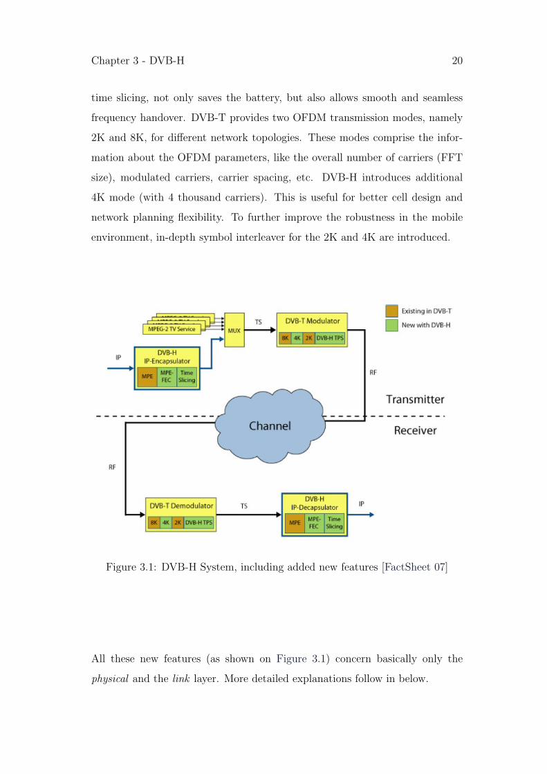
Chapter 3 - DVB-H 20
time slicing, not only saves the battery, but also allows smooth and seamless
frequency handover. DVB-T provides two OFDM transmission modes, namely
2K and 8K, for different network topologies. These modes comprise the infor-
mation about the OFDM parameters, like the overall number of carriers (FFT
size), modulated carriers, carrier spacing, etc. DVB-H introduces additional
4K mode (with 4 thousand carriers). This is useful for better cell design and
network planning flexibility. To further improve the robustness in the mobile
environment, in-depth symbol interleaver for the 2K and 4K are introduced.
Figure 3.1: DVB-H System, including added new features [FactSheet 07]
All these new features (as shown on Figure 3.1) concern basically only the
physical and the link layer. More detailed explanations follow in below.

Chapter 3 - DVB-H 21
3.2 Innovations in the physical layer
The physical layer of DVB-H is performed by the means of the DVB-T standard
using OFDM modulation [Kornfeld 05]. It consists of the DVB-T modulator and
demodulator. This means that the DVB-H data streams are absolutely compat-
ible with basic DVB-T transport streams. This feature results in a guarantee
that DVB-H streams are able to be broadcast not only in networks totally ded-
icated to DVB-H services, but also in networks where DVB-H streams are only
additions to DVB-T streams. To distinguish a DVB-H signal from an DVB-T
signal, one mandatory new feature is introduced in the physical layer of DVB-H
- it is the TPS signaling for the DVB-H streams in the multiplex. To fulfill other
characteristic requirements for mobile environment, techniques like time slicing
or MPE-FEC are put onto higher, link level.
For reasons of backwards compatibility, there was an ambition to introduce just
few changes in DVB-H. Nevertheless, there are some other new features in the
physical layer, which are however not mandatory. A new OFDM 4K mode and
an in-depth interleaver are introduced in DVB-H.
3.2.1 Signaling in the TPS-bits
TPS-bits are known already from the DVB-T standard. However, DVB-H cre-
ates some new elements of the TPS channel. The purpose of these additional
TPS-bits is to signal the presence of time slicing and MPE-FEC as well as
the 4K mode option. Broadcasting of the cell identifier, which was optional in
DVB-T, is in DVB-H made obligatory [TR 102 377]. TPS-bits are very robust
and in addition to that, demodulating of the carried information can be pro-
cessed much faster than demodulating of SI-tables (Service Information) or the
MPE-header.

Chapter 3 - DVB-H 22
3.2.2 OFDM transmission modes
DVB standards are based on OFDM transmission system. It is advantageous
to use different OFDM parameters for different environment scenarios. The set
of OFDM parameters are called modes. DVB-T uses two modes, particularly
2K and 8K mode, which correspond to about two thousand and eight thousand
OFDM carriers respectively. Since the 8K mode has four times as many carriers
than 2K, its carrier spacing is four times lower. This means that 8K mode
can offer better maximum distance of transmitters, but consequently it is also
more sensitive to Doppler effects. On the other hand, in the 8K mode, the
mobile receiver process the transmission at lower speeds compared to 2K. The
comparison between OFDM transmission modes is shown in the Table 3.1.
Table 3.1: Signal parameters for possible DVB-H OFDM transmission modes
[Kornfeld 05]
Since the network planning of DVB-H carries some additional challenges, it is
very useful if the system provides more flexibility. That is why DVB-H intro-
duces an additional OFDM transmission mode (4K) using 4096 FFT size, which
represents a compromise solution between the 2K and 8K modes. It suppose to
fill the gap of DVB-T modes and thus should be the alternative solution for the
trade-offs between coverage area and mobility [Bennett], [Faria 02].
Chapter 3 - DVB-H 23
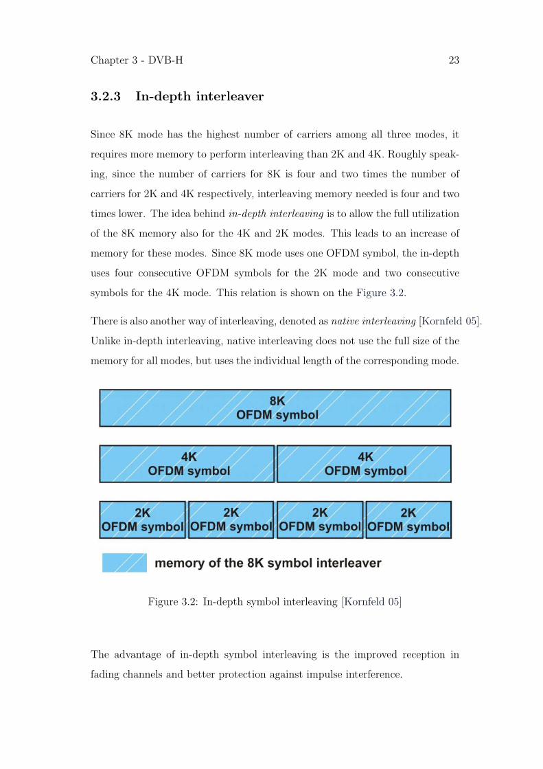
3.2.3 In-depth interleaver
Since 8K mode has the highest number of carriers among all three modes, it
requires more memory to perform interleaving than 2K and 4K. Roughly speak-
ing, since the number of carriers for 8K is four and two times the number of
carriers for 2K and 4K respectively, interleaving memory needed is four and two
times lower. The idea behind in-depth interleaving is to allow the full utilization
of the 8K memory also for the 4K and 2K modes. This leads to an increase of
memory for these modes. Since 8K mode uses one OFDM symbol, the in-depth
uses four consecutive OFDM symbols for the 2K mode and two consecutive
symbols for the 4K mode. This relation is shown on the Figure 3.2.
There is also another way of interleaving, denoted as native interleaving [Kornfeld 05].
Unlike in-depth interleaving, native interleaving does not use the full size of the
memory for all modes, but uses the individual length of the corresponding mode.
Figure 3.2: In-depth symbol interleaving [Kornfeld 05]
The advantage of in-depth symbol interleaving is the improved reception in
fading channels and better protection against impulse interference.

Chapter 3 - DVB-H 24
3.3 Link Layer
As shown above, DVB-H uses almost the same physical layer as DVB-T, with
only small extensions. That is the reason why DVB-H can be backward com-
patible with DVB-T [DigiTAG 05]. However, there are still some major require-
ments to be fulfilled for the ability of mobile video delivery. These are addressed
to the link layer. This layer provides the most significant changes compared to
DVB-T.
Given the requirement of power saving, DVB-H introduces a special technique
called time slicing. It results in remarkable battery saving effect and additionally
allows soft handover. To solve the issues of robustness and poor signal reception
conditions, a new error protection scheme called MPE-FEC (Multi-Protocol En-
capsulation Forward Error Correction) is introduced (graphically shown on the
Figure 3.3). This scheme employs Reed-Solomon channel coding.
Figure 3.3: Conceptual structure of DVB-H receiver [EN 302 304]
These major extensions are described in the following sections.
3.3.1 Time Slicing
In traditional continuous mode (as used in DVB-T MPEG-2 data transmis-
sion), several services (e.g. TV programs) are transmitted in one transport

Chapter 3 - DVB-H 25
stream. The services are multiplexed together and transmitted in parallel
[Henriksson 05]. Therefore, it is not possible to receive only one transport
stream, but the receiver has to process all the data (see Figure 3.4) and af-
terwards choose desired stream (service). This obviously leads to high power
consumption.
Figure 3.4: Continual transmission structure [Kangas 06]
The objective of time-slicing is to reduce the average power consumption of
the terminal and enable smooth and seamless service handover [EN 302 304].
The technique is based on the TDM (Time Division Multiplexing), which has
long been used in communications systems for providing services to different
users in different time slots over common media [Yang Song 04]. Services are
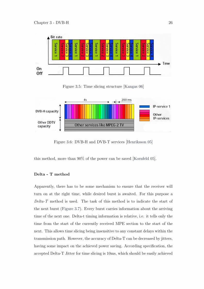
not longer transmitted in parallel, but consecutively in time slots, called bursts.
These bursts have not necessarily the same duration, which is illustrated on the
Figure 3.5.
From this follows, that the full DVB-H data capacity is always used only by
one service for a fraction of time (say 200ms). After this, another service is
transmitted and then another, and so on. After couple of services, the first
service is again in the air. This is shown on the Figure 3.6, where the period
between sending the same service for this example is 4s.
Hence, in contrast to DVB-T, it is possible to receive only the desired service.
Receiver is receiving data only in a short time, while processing the desired
service burst. During the waiting time for the next burst, it is turned off. Using
Chapter 3 - DVB-H 26
Figure 3.5: Time slicing structure [Kangas 06]
Figure 3.6: DVB-H and DVB-T services [Henriksson 05]
this method, more than 90% of the power can be saved [Kornfeld 05].
Delta - T method
Apparently, there has to be some mechanism to ensure that the receiver will
turn on at the right time, while desired burst is awaited. For this purpose a
Delta-T method is used. The task of this method is to indicate the start of
the next burst (Figure 3.7). Every burst carries information about the arriving
time of the next one. Delta-t timing information is relative, i.e. it tells only the
time from the start of the currently received MPE section to the start of the
next. This allows time slicing being insensitive to any constant delays within the
transmission path. However, the accuracy of Delta-T can be decreased by jitters,
having some impact on the achieved power saving. According specification, the
accepted Delta-T Jitter for time slicing is 10ms, which should be easily achieved

Chapter 3 - DVB-H 27
[EN 301 192].
Figure 3.7: Delta-T method [EN 301 192]
Another benefit of using relative delta-t time instead of absolute, is that there
is no need for special synchronization between the transmitter and receiver
[Bennett].
Burst parameters
There has been always an effort from two sides for getting better support of
various services in mobile environment. Firstly, it is a still present effort of
increasing the transmission data rates. Secondly, it is an ambition for getting
better content compression schemes (e.g. video compression), roughly speaking,
it is an effort for decreasing the data rates of the content. The fact that trans-
mission data rates in today’s mobile networks are much higher than data rates
needed for delivering ”high quality” video1 allows the using of time slicing and
1”High quality” video was defined in chapter 1 as any video with data rate higher than
200 kbps
Chapter 3 - DVB-H 28
thereby battery saving.
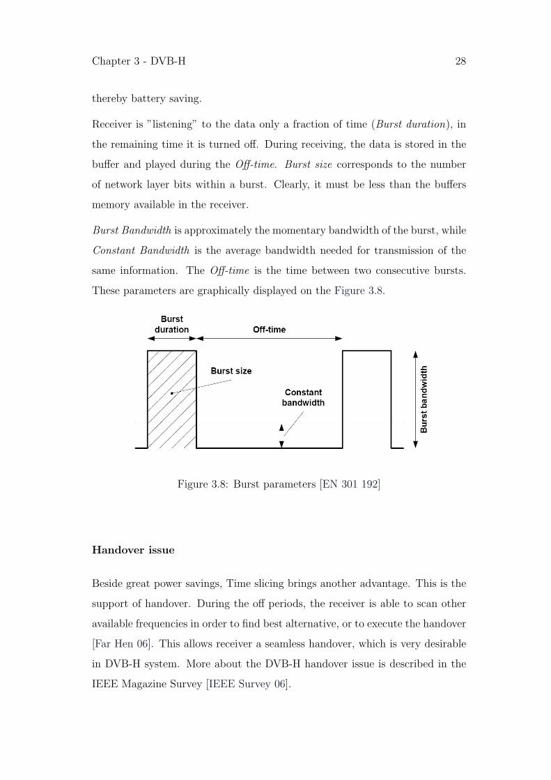
Receiver is ”listening” to the data only a fraction of time (Burst duration), in
the remaining time it is turned off. During receiving, the data is stored in the
buffer and played during the Off-time. Burst size corresponds to the number
of network layer bits within a burst. Clearly, it must be less than the buffers
memory available in the receiver.
Burst Bandwidth is approximately the momentary bandwidth of the burst, while
Constant Bandwidth is the average bandwidth needed for transmission of the
same information. The Off-time is the time between two consecutive bursts.
These parameters are graphically displayed on the Figure 3.8.
Figure 3.8: Burst parameters [EN 301 192]
Handover issue
Beside great power savings, Time slicing brings another advantage. This is the
support of handover. During the off periods, the receiver is able to scan other
available frequencies in order to find best alternative, or to execute the handover
[Far Hen 06]. This allows receiver a seamless handover, which is very desirable
in DVB-H system. More about the DVB-H handover issue is described in the
IEEE Magazine Survey [IEEE Survey 06].
Chapter 3 - DVB-H 29
3.3.2 MPE - FEC
Multi-Protocol Encapsulation
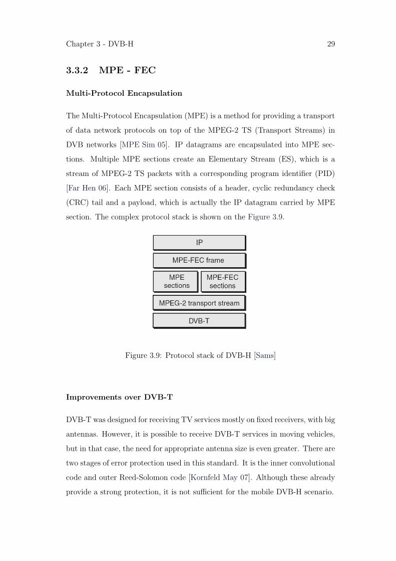
The Multi-Protocol Encapsulation (MPE) is a method for providing a transport
of data network protocols on top of the MPEG-2 TS (Transport Streams) in
DVB networks [MPE Sim 05]. IP datagrams are encapsulated into MPE sec-
tions. Multiple MPE sections create an Elementary Stream (ES), which is a
stream of MPEG-2 TS packets with a corresponding program identifier (PID)
[Far Hen 06]. Each MPE section consists of a header, cyclic redundancy check
(CRC) tail and a payload, which is actually the IP datagram carried by MPE
section. The complex protocol stack is shown on the Figure 3.9.
Figure 3.9: Protocol stack of DVB-H [Sams]
Improvements over DVB-T
DVB-T was designed for receiving TV services mostly on fixed receivers, with big
antennas. However, it is possible to receive DVB-T services in moving vehicles,
but in that case, the need for appropriate antenna size is even greater. There are
two stages of error protection used in this standard. It is the inner convolutional
code and outer Reed-Solomon code [Kornfeld May 07]. Although these already
provide a strong protection, it is not sufficient for the mobile DVB-H scenario.
Chapter 3 - DVB-H 30
In contrast to DVB-T, receivers in DVB-H networks are generally in motion and
are characterized by small antennas. In addition to that, signal transmission has
to deal with multipath effects like frequency selective fading and Doppler effects.
Of course, in such scenarios, one can assume a high level of man-made noise.
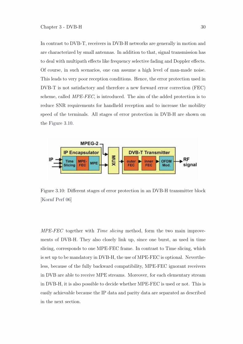
This leads to very poor reception conditions. Hence, the error protection used in
DVB-T is not satisfactory and therefore a new forward error correction (FEC)
scheme, called MPE-FEC, is introduced. The aim of the added protection is to
reduce SNR requirements for handheld reception and to increase the mobility
speed of the terminals. All stages of error protection in DVB-H are shown on
the Figure 3.10.
Figure 3.10: Different stages of error protection in an DVB-H transmitter block
[Kornf Perf 06]
MPE-FEC together with Time slicing method, form the two main improve-
ments of DVB-H. They also closely link up, since one burst, as used in time
slicing, corresponds to one MPE-FEC frame. In contrast to Time slicing, which
is set up to be mandatory in DVB-H, the use of MPE-FEC is optional. Neverthe-
less, because of the fully backward compatibility, MPE-FEC ignorant receivers
in DVB are able to receive MPE streams. Moreover, for each elementary stream
in DVB-H, it is also possible to decide whether MPE-FEC is used or not. This is
easily achievable because the IP data and parity data are separated as described
in the next section.

Chapter 3 - DVB-H 31
MPE-FEC frame
MPE-FEC frame is organized as a matrix with constant number of 255 columns
and a variable number of rows. The information about the number of rows is
carried in the service information (SI) and gains the common values of 256, 512,
768, or maximum 1024 [Far Hen 06]. Since one cell of the frame corresponds to
one byte, a MPE-FEC frame (and thus a time sliced burst) of maximum size
(with 1024 rows) would be almost 2 Mbits large.
MPF-FEC frame is composed of two parts; Application data table (ADT) with
191 columns and RS (Reed Solomon) data table with remaining 64 columns (see
Figure 3.11). The data itself, carried in form of IP datagrams, fill the ADT.
These are the information bits, which are intended to be protected. In the
RS data table is the parity information calculated from the ADT using a Reed
Solomon code.
Figure 3.11: MPE-FEC frame [Lopez 06]
• RS coding
IP datagrams are located in the frame one after another, starting in the

Chapter 3 - DVB-H 32
upper left corner of the matrix and continuing vertically - column wise.
There is no space left between datagrams, although they might be of
different lengths. If a datagram does not finish until the end of a column,
it proceeds to the next column. When all datagrams are included in the
frame, the remaining unoccupied byte positions are filled with padding
bytes (all zero bytes).
RS data table is filled with parity bytes calculated from the IP datagrams
and possible padding bytes from the ADT. Certain code generator polyno-
mial and field generator polynomial are used for this Reed Solomon code
RS (255, 191). Using these technique, the RS data table is completely
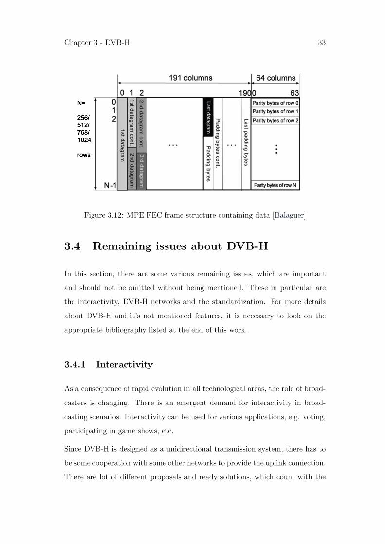
filled and thus the MPE-FEC frame is completed [TR 102 377].
• Block interleaving
In addition to the powerful coding mechanism, MPE-FEC frame structur-
ing contains a block interleaving effect [Kornfeld May 07]. This is achieved
by the different direction of writing/reading process and coding. Partic-
ularly, writing to and reading from the MPE-FEC data frame is done
vertically, in column direction, whereas coding is performed horizontally,
in row direction (as clearly shown on the Figure 3.12). The outcome is an
interleaving effect applied over the whole data [Kornfeld May 07].
Decoding
Very important feature in the decoding mechanism is the CRC-32 code protec-
tion, which is used instead of checksums. It tells the receiver whether a message
was corrupted or not. Bytes are marked as reliable or unreliable. For more
details of how decoding mechanism in DVB-H works, or more details about
different decoding methods, see [TR 102 377] and [Himmanen 06] respectively.
Chapter 3 - DVB-H 33
N=
256/512/768/1024
rows
Figure 3.12: MPE-FEC frame structure containing data [Balaguer]
3.4 Remaining issues about DVB-H
In this section, there are some various remaining issues, which are important
and should not be omitted without being mentioned. These in particular are
the interactivity, DVB-H networks and the standardization. For more details
about DVB-H and it’s not mentioned features, it is necessary to look on the
appropriate bibliography listed at the end of this work.
3.4.1 Interactivity
As a consequence of rapid evolution in all technological areas, the role of broad-
casters is changing. There is an emergent demand for interactivity in broad-
casting scenarios. Interactivity can be used for various applications, e.g. voting,
participating in game shows, etc.
Since DVB-H is designed as a unidirectional transmission system, there has to
be some cooperation with some other networks to provide the uplink connection.
There are lot of different proposals and ready solutions, which count with the
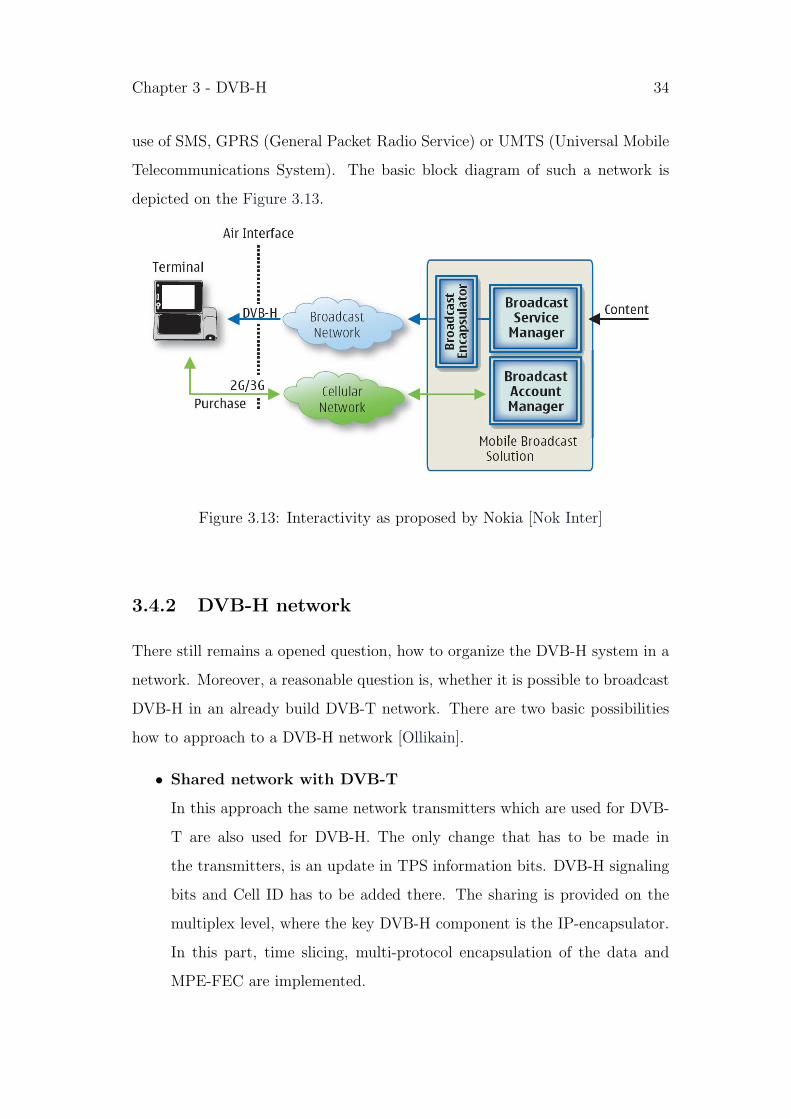
Chapter 3 - DVB-H 34
use of SMS, GPRS (General Packet Radio Service) or UMTS (Universal Mobile
Telecommunications System). The basic block diagram of such a network is
depicted on the Figure 3.13.
Figure 3.13: Interactivity as proposed by Nokia [Nok Inter]
3.4.2 DVB-H network
There still remains a opened question, how to organize the DVB-H system in a
network. Moreover, a reasonable question is, whether it is possible to broadcast
DVB-H in an already build DVB-T network. There are two basic possibilities
how to approach to a DVB-H network [Ollikain].
• Shared network with DVB-T
In this approach the same network transmitters which are used for DVB-
T are also used for DVB-H. The only change that has to be made in
the transmitters, is an update in TPS information bits. DVB-H signaling
bits and Cell ID has to be added there. The sharing is provided on the
multiplex level, where the key DVB-H component is the IP-encapsulator.
In this part, time slicing, multi-protocol encapsulation of the data and
MPE-FEC are implemented.

Chapter 3 - DVB-H 35
• DVB-H Dedicated network
In dedicated network, the full multiplex and the complete RF (Radio
Frequency) channel serve to DVB-H transmissions. Dedicated approach
takes advantage over the shared network mostly by the means of freedom
of planning. This is increased due to the possible use of the additional
OFDM 4K mode or in depth interleavers, which were introduced in DVB-
H standard.
A typical dedicated network is composed of several SFN (Single Frequency
Network) areas, which then create an MFN (Multi Frequency Network).
The maximum size of such a SFN is typically in the order of tens of
kilometers and depends on several parameters, like the FFT size and guard
interval [Far Hen 06]. Furthermore, the geographical aspect has to be
taken into account.
Practical drawback of this approach is the low number of users, who has
to bear the costs. But this problem should be solved by the increase of
availability and popularity of DVB-H.
IP Datacast
One of the major differences between DVB-T and DVB-H, which has not yet
been mentioned, is that DVB-T is a transmission system based on MPEG-2
transport streams, whereas DVB-H is IP based. This allows the system much
better interoperability with other networks as defined in IP Datacast. IP Data-
cast is a system which makes it possible to employ broadcast content and mobile
communications services on a single device [May]. This is very useful thinking
especially of combining classical (but mobile) telephone services with the digital
TV services of DVB-H, but also for the interactivity issue.
IP Datacast is a set of individual specifications, with an intention to form an
overall system comprising different networks. These are specified in several doc-
Chapter 3 - DVB-H 36
uments, which can be found on the official DVB-H webpage http://www.dvb-
h.org.
The key components of DVB IP Datacast are: ESG (Electronic Service Guide),
CDP (Content Delivery Protocols), SPP (Service Purchase and Protection),
PSI/SI (Programme Specific Information/Service Information) [FactIP 07].
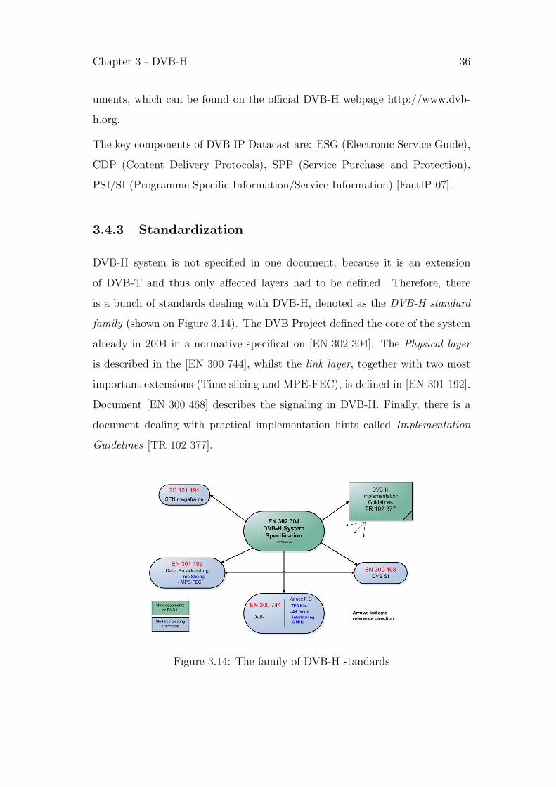
3.4.3 Standardization
DVB-H system is not specified in one document, because it is an extension
of DVB-T and thus only affected layers had to be defined. Therefore, there
is a bunch of standards dealing with DVB-H, denoted as the DVB-H standard
family (shown on Figure 3.14). The DVB Project defined the core of the system
already in 2004 in a normative specification [EN 302 304]. The Physical layer
is described in the [EN 300 744], whilst the link layer, together with two most
important extensions (Time slicing and MPE-FEC), is defined in [EN 301 192].
Document [EN 300 468] describes the signaling in DVB-H. Finally, there is a
document dealing with practical implementation hints called Implementation
Guidelines [TR 102 377].
Figure 3.14: The family of DVB-H standards
Chapter 4
HSDPA MEASUREMENTS
The aim of this work is to evaluate the performance of the chosen video delivery
technologies. This can be done by several different ways. One possibility is to
investigate the delivery at the very lower layer, looking for packet losses, bit
rates, etc. For this work, an upper layer approach was chosen, looking at the
received video. The evaluation is based on the measurement of video quality. For
this purpose the received video was recorded in different scenarios and compared
it to its original. Note that that only video, no audio streams, were recorded
and measured.
Since mobile TV is expected to be used in various situations, measurements
were performed in different scenarios. Despite the mobile nature of this service,
it is assumed that TV will be watched also in fixed situations, for instance
while waiting on the bus station, or inside the building. Therefore, the chosen
scenarios include a simple indoor and outdoor environment without any or small
movement. In addition, some truly moving scenario is very typical for mobile
environment and therefore was investigated as well.
For providing the measurements, there was an ambition to use a promising video
content for mobile TV environment. This in particular includes sport (football),
news and music clips [Knoche 05]. However, measuring the same videos was only
possible in the HSDPA case. With the use of a streaming server, it was possible
37

Chapter 4 - HSDPA MEASUREMENTS 38
to stream any arbitrary video. On that account, one could study the desired
videos in all chosen scenarios. This was not workable in the DVB-H case as it
is described in chapter 5.
Before stating the HSDPA measurement results, some information about the
measured videos, about the scenarios and tools is offered. Furthermore, in this
section there is an exact procedure description of the video quality analyses.
4.1 Scenarios
All measurements were provided in 3 different scenarios in the Vienna city.
The ambition was to test the most promising scenarios for the mobile TV use
and thus to emulate the real usage scenarios. It is expected that videos, will
be watched in a indoor environment. Furthermore, the utilization in a truly
mobile environment is expected, e.g. traveling in a tram, train or a car. With
the growing popularity of the HSDPA service, it is expected that some cells will
experience high traffics at some parts of the day.
Chosen scenarios for this work include the Indoor scenario, the Tram scenario
and the Pedestrian scenario and all of them are experiencing high data traffic.
4.1.1 Indoor scenario
The indoor scenario was measured at the Institute of Communications and
Radio-Frequency Engineering of the Vienna University of Technology. This
place was chosen for three reasons: relative high traffic in cell, good signal
strength and convenient working conditions (since it was measured at the place
of work for this thesis). The map on Figure 4.1 shows the indoor location and
the base station of the corresponding cell. The average HSDPA traffic of the
cell during the measurements is shown on the Figure 4.2.

Chapter 4 - HSDPA MEASUREMENTS 39
Figure 4.1: Indoor scenario location and the corresponding base station
Figure 4.2: Average HSDPA traffic in time during the Indoor measurements
4.1.2 Tram scenario
The tram scenario was measured at the centre of Vienna, while traveling in the
tram number 1. The route of this tram is shown on the Figure 4.3. It was

Chapter 4 - HSDPA MEASUREMENTS 40
expected that during the streaming and measuring this scenario it would come
to more handovers. This was also the reason of providing this measurement, to
investigate the quality in a environment with high data traffic and handovers.
Figure 4.3: The measurement route of the Tram scenario
4.1.3 Pedestrian
The Pedestrian scenario was measured in a cell which previously showed high
traffic and was proposed by the cooperating mobile provider. The area of Hi-
etzinger Kai and Hackinger Strasse was chosen. It is shown on the Figure 4.4
together with the base station. This scenario was measured outdoor, sitting on
a bench or walking little bit on the street. However, the movements were not

Chapter 4 - HSDPA MEASUREMENTS 41
fast, since it is not expected that anybody will be watching some videos while
fastly walking or even running. However this was a difficult scenario with lot
of fading, because the measurements were provided behind big buildings. The
Figure 4.4: Pedestrian scenario location and the corresponding base station
average HSDPA traffic of the cell during the measurements is shown on the
Figure 4.5.
4.2 Video Content
As already stated in the beginning of this chapter, there were 3 different types
of the most frequent video content used for this work (the captures are shown
on the Figure 4.6): football, news and music clip.
The major characteristics of football are the prevailing green field and the fast
moving ball. Therefore it is expected that the streaming of this video will lead
to more transmission errors than the news.

Chapter 4 - HSDPA MEASUREMENTS 42
Figure 4.5: Average HSDPA traffic in time during the Pedestrian measurements
Figure 4.6: Video content
The news video is characterized by very few and slow changes which naturally
is expected to result in better performance.
The music clip is a mixture of different characteristics. On the one hand the
scenes in the particular video are not moving fast, but on the other hand, they
are changing very quickly.
4.3 Tools
There are a number of different programs and tools, which were used for pro-
viding this performance evaluation.
Firstly, some tools for video preparation were needed. For this purpose, VLC
Chapter 4 - HSDPA MEASUREMENTS 43
media player was used for transcoding, Camtasia Studio for adding black and
white sequences and QuickTime for adding the hinted track.
Videos were streamed by the Darwin Streaming Server (DSS) and were received
and played either on QuickTime or VLC. This was then captured using Camtasia
Studio, synchronized to its original by VirtualDub and processed by Matlab for
demanding computations.
Along the way, packet analyzes were provided using Wireshark. To be able to
remotely access the streaming server and thus capture the packet network also
on server side, an PuTTy client for SSH (Secure Shell) connection and Xming
for the graphical interface were used.
As final remark, Linux computer was used as a server, and Windows laptop
with an HSDPA PCM/CIA card, supporting data rates up to 3,6 Mbps, as a
client (receiver).
All the mentioned programs are shortly described below:
• VLC media player (v.0.8.6c) - is a highly portable media player produced
by VideoLAN project [VideoLAN]. Beside the basic player functionality,
it is able to stream over network, to transcode multimedia files and save
them to various different formats.
• QuickTime player (v.7.1.3) - is a multimedia framework developed by
[Apple]. It is capable of handling various formats of digital video, me-
dia clips, music, animation, etc. Because it is a part of the QuickTime
family of digital creation it can prepare videos for streaming (adding a
hinted track).
• Camtasia Studio (v.4) - is a video screen capturing and recording program,
which allows some additional editing of the video. It is published by
[TechSmith].

Chapter 4 - HSDPA MEASUREMENTS 44
• VirtualDub (v.1.6.19.) - is a video capture/processing utility for 32-bit
Windows platforms. It is streamlined for fast linear operations over video.
It has batch-processing capabilities for processing large numbers of files.
• Darwin Streaming Server (v.5) - is an open sourced RTP/RTSP (real-time
protocols) streaming server, capable of streaming a variety of media types
including H.264. It is developed by Apple and thus based on the source
code of QuickTime Streaming Server.
• Matlab (v.6.4) - is a numerical computing environment and programming
language, created by [MathWorks].
• Wireshark (v.0.99.6a) - formerly known as Ethereal, is a protocol network
analyzer [Wireshark].
• PuTTy (v.0.60)- is a SSH client (usable also for other network protocols),
which enables to create an SSH connection to remote computer.
• Xming (v.6.9.0.24) - is a port of the X Window System to the Microsoft
Windows operating system. With implementation of SSH, it can be used
to securely forward X11 session from UNIX machines. This is helpful for
getting graphical interface.
4.4 Methodology
To be able to measure the received video quality, there were some steps needed to
be done in prior. The videos had to be transcoded and prepared for streaming,
streaming server had to be installed, some method of video capturing had to be
proposed and finally, the results had to be calculated. The methodology of all
these steps is described below.

Chapter 4 - HSDPA MEASUREMENTS 45
4.4.1 Set-up of video sequences
Videos had to be prepared for the use in the test bed. In particularly, the initial
aim was to analyze ”high quality” video, which was defined in chapter 1 as a
video of data rate higher than 200 kbps. There is of course a natural effort
that this data rate will not be too high in streaming applications. Hence, an
effective compression mechanism is needed to achieve sufficient video quality,
while retaining the desired data rate. Additional important parameter for video
quality is the number of frames per second denoted as FPS (Frames per Second).
Furthermore, to enable streaming of a particular video sequence, a hinted track
has to be added to each video. This is necessary for the streaming server to
control the SDP sessions.
Moreover, some additional black and white sequences were added to the videos.
Each was of duration of 1 second. Three of them were put in mixed order before
the beginning of the video. One was added at the end. All of them were removed
after the streaming and capturing and are not included in measurements results.
This step was realized for reasons of more comfortable handling with videos and
easier preparation for latter processing.
The desired streamed video started after 3 seconds of black and white sequences,
which was sufficient time for the streaming applications VLC and QuickTime
to be completely loaded. Especially VLC takes a longer time to start playing
the streamed video. Using this method one could be sure that at the time when
the desired video starts, video window already appeared on the screen.
As a second reason, it was very easy to identify the beginning and the end of
the desired captured video.
The setting up of the videos consisted of three steps:
1. video transcoding to H.264 codec with 256 kbps bit rate and 12 FPS
2. adding of the black and white sequences
3. augmentation by a hinted track

Chapter 4 - HSDPA MEASUREMENTS 46
Videos were saved in the 3GP video container format, which was accepted for
use by the Darwin Streaming Server (DSS).
Parameters of the prepared videos are shown in the Table 4.1.
Table 4.1: Video content
Although, the video was initially transcoded to 256 kbps, this rate was increased
by adding the hinted track.
4.4.2 Streaming server setup
DSS was installed on a Linux desktop computer in the laboratory room. Al-
though there are possibilities to set up a streaming playlist, it was needless, since
only streaming on demand was desired. For this reason, prepared videos were
just copied onto the streaming server. Furthermore it was necessary to take out
the IP address of the streaming server out of the firewalls of the institute, to be
able to access it. The access to the videos from the client is carried out through
RTSP (e.g. rtsp://128.131.x.y/news.3gp).
Chapter 4 - HSDPA MEASUREMENTS 47
4.4.3 Streaming and recording
There is a variety of possibilities for playing the streamed videos. For this work,
two of them were chosen: QuickTime player and VideoLAN player. During the
streaming process, the video was captured using Camtasia recorder. Since the
streamed video was of 12 FPS, the capturing was set to its double rate - 24 FPS.
The capturing and the consecutive processing and calculations were performed
in RAW format, using an AVI (Audio Video Interleave) multimedia container.
The same procedure was repeated in all defined scenarios and with both video
players.
4.4.4 Packet analyses
At the same time with previous described measurements, network analyses were
provided. Shortly before the beginning of streaming, the Wireshark analyses
were started. Wireshark for network packet analyses was installed and measured
on both, streaming server and the client (laptop). There was a need to capture
the packet traffic also while measuring in the outdoor scenarios. Therefore
Xming and Putty (SSH client) were installed on the client to provide remote
access to the streaming server.
4.4.5 Video processing and calculations
Captured video had to be compared to its original. But firstly, they had to
be absolutely synchronized; i.e. the number and positions of frames had to
be exactly the same. For this reason, the added black and white sequences
were very helpful. In addition to that, the received video and its original were
synchronized in VirtualDub, i.e. some frames were dropped to ensure that
remaining frames of the received video are at the same position as the frames
of its original.

Chapter 4 - HSDPA MEASUREMENTS 48
For the evaluation of the video quality, a PSNR (Peak Signal to Noise Ratio)
video quality metric was chosen. It is a measurement of the mean error between
the original and corrupted video as a ratio of the peak signal level, expressed
in dB. PSNR is the simplest and most common objective video quality metric
[Wang], [Winkler] and it is defined via mean squered error (MSE) as:
PSNR = 10 · log10
(MAX 2
MSE
)(4.1)
where MSE, which for two mxn monochrome images I and K, where one of the
images is considered a noisy approximation of the other, is defined as:
PSNR = 10 · log10
(255 2
1mn
∑m−1i=0
∑n−1j=0 ||I(i, j) − K(i, j)||2
)(4.2)
MAX is the maximum pixel value of the image. In case of this work, the pixels
where represented by an 8 bit value, which implies the MAX to be 255.
This algorithm was written in Matlab and is added in Appendix.
4.5 Results
4.5.1 QuickTime vs. VLC
It was expected that streaming through QuickTime (QT) player would show dif-
ferent results than through VLC player. This fact was approved already during
the first test measurements. The streamed video showed viewable better quality
using QT player. In VLC, more transmission errors occurred. Accordingly it
was decided to provide all measurements in both players.
The reason for the better QT performance has become evident after doing the
network analyses. Both players were set up to provide the streaming in RTP over
UDP. It was discovered, that QT is regularly sending some RTCP feedback ac-
knowledgments. The whole communication between server and client consisted

Chapter 4 - HSDPA MEASUREMENTS 49
of approximately 65% of RTP (the data itself) and 35% of RTCP packets. There
were no acknowledgements sent in VLC. The only RTCP packets in this case,
were the ’sender’ and ’receiver reports’. Therefore the communication consisted
of almost 99% of RTP and 1% of RTCP packets.
To explain this fact, it is necessary to remind, that the DSS server is an open
source version of Apple’s QuickTime Streaming Server technology. These are
set up to provide the best performance when working together with QuickTime
player. When the player detects that it is streaming from a known server,
it automatically involves the RTCP feedback technology, which leads to the
increased performance.
Figure 4.7: QT and VLC comparison of the data packet flow - Football
Another difference in the streaming process of QT and VLC was the data packet
flow. Figures 4.7, 4.8 and 4.9 show the graphs of football, news and music video
data packet flow in the indoor scenario. The flows in other scenarios were very

Chapter 4 - HSDPA MEASUREMENTS 50
similar.
Figure 4.8: QT and VLC comparison of the data packet flow - News
QT is transmitting more amounts of data at the beginning of streaming. Hence,
at the end (cca. the last 20 seconds) there is no more data sent. The transmission
in VLC is processed more or less continuously. This buffer scheduling makes
QuickTime player much more robust for working in severe conditions.
The horizontal line in the graphs shows the approximate average data rate of
the video. The vertical line, shows the end of the video, including the black and
white sequences discussed in subsection 4.4.1.
4.5.2 Network analyses
The previous mentioned different streaming strategy between Quicktime and
VLC was clearly seen after doing the network analyses. The packet network
traffic of VLC is shown in the Table 4.2. It shows the average number of
packets for particular scenario and video content. The table shows only the
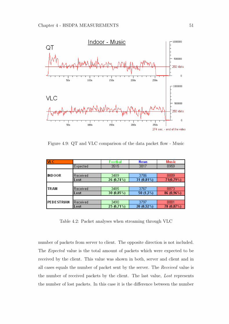
Chapter 4 - HSDPA MEASUREMENTS 51
Figure 4.9: QT and VLC comparison of the data packet flow - Music
Table 4.2: Packet analyses when streaming through VLC
number of packets from server to client. The opposite direction is not included.
The Expected value is the total amount of packets which were expected to be
received by the client. This value was shown in both, server and client and in
all cases equals the number of packet sent by the server. The Received value is
the number of received packets by the client. The last value, Lost represents
the number of lost packets. In this case it is the difference between the number

Chapter 4 - HSDPA MEASUREMENTS 52
of sent (expected) and received packets.
The network analyses when using QuickTime player was more complicated. It
is shown in the Table 4.3. The Expected value was still present at the server
Table 4.3: Packet analyses when streaming through QT
and receiver. However, looking at the server shows, that the total number of
Sent packets is higher than the number of expected. This is another prove that
there must be some retransmission mechanism when using QuickTime player.
The difference between sent and expected values yields the number of Retrans-
missions. For these reasons it can happen (and it happened in all cases in this
work), that also the number of Received packets is higher than the number
of expected. The final packet loss is the difference between sent and received
packets and is represented by the Lost value.
Altogether, these results show us that there is a different streaming strategy for
QuickTime and VLC players.

Chapter 4 - HSDPA MEASUREMENTS 53
4.5.3 PSNR analyses
Using the Equation 4.1, PSNR was calculated from every measured video se-
quence. An example of such PSNR graph is shown on the Figure 4.10. It shows
0 1000 2000 3000 4000 5000 6000 7000 80000
10
20
30
40
50
60
70
80
90
100PSNR − Football − INDOOR (VLC)
Frames
PS
NR
[dB
]
Figure 4.10: Example of PSNR graph for soccer in the Indoor scenario
the PSNR value of every frame of the video sequence. There are some frames
with almost 100 dB PSNR. These present the non corrupted frames compared
to the original. Calculating the PSNR of these frames would go to infinity,
therefore some clipping mechanism had to be involved in the Matlab algorithm.
However, showing the results in the form of PSNR values is not very clear.
Therefore the results are presented in histograms, showing the empirical PDF
(Probability Density Function). It shows the standardized amount of frames
with particular PSNR value. The distance between two consecutive histograms
is 3 dB. Every of the following graphs present mainly 3 or more video sequences
measured in particular scenario and video player (i.e. more than 5 minutes of

Chapter 4 - HSDPA MEASUREMENTS 54
football and news and more than 12 minutes of music). All PDF results are
shown in the figures 4.11, 4.12, 4.13, 4.14, 4.15, 4.16, 4.17, 4.18 and 4.19.

Chapter 4 - HSDPA MEASUREMENTS 55
Indoor
10 20 30 40 50 60 70 80 90 1000
0.1
0.2
0.3
0.4
0.5
0.6
0.7
0.8
0.9
1PDF − Football − INDOOR
PSNR [dB]
Empi
rical
PD
F
10 20 30 40 50 60 70 80 90 1000
0.1
0.2
0.3
0.4
0.5
0.6
0.7
0.8
0.9
1PDF − Football − INDOOR (VLC)
PSNR [dB]
Empi
rical
PD
F
Figure 4.11: PDF of Football in Indoor scenario for QuickTime and VLC
10 20 30 40 50 60 70 80 90 1000
0.1
0.2
0.3
0.4
0.5
0.6
0.7
0.8
0.9
1PDF − News − INDOOR
PSNR [dB]
Empi
rical
PD
F
10 20 30 40 50 60 70 80 90 1000
0.1
0.2
0.3
0.4
0.5
0.6
0.7
0.8
0.9
1PDF − News − INDOOR (VLC)
PSNR [dB]
Empi
rical
PD
F
Figure 4.12: PDF of News in Indoor scenario for QuickTime and VLC
10 20 30 40 50 60 70 80 90 1000
0.1
0.2
0.3
0.4
0.5
0.6
0.7
0.8
0.9
1PDF − Music − INDOOR
PSNR [dB]
Empi
rical
PD
F
10 20 30 40 50 60 70 80 90 1000
0.1
0.2
0.3
0.4
0.5
0.6
0.7
0.8
0.9
1PDF − Music − INDOOR (VLC)
PSNR [dB]
Empi
rical
PD
F
Figure 4.13: PDF of Music in Indoor scenario for QuickTime and VLC
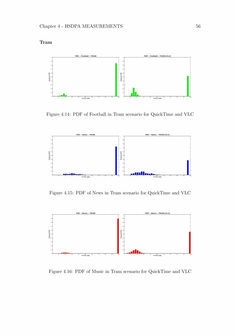
Chapter 4 - HSDPA MEASUREMENTS 56
Tram
10 20 30 40 50 60 70 80 90 1000
0.1
0.2
0.3
0.4
0.5
0.6
0.7
0.8
0.9
1PDF − Football − TRAM
PSNR [dB]
Empi
rical
PD
F
10 20 30 40 50 60 70 80 90 1000
0.1
0.2
0.3
0.4
0.5
0.6
0.7
0.8
0.9
1PDF − Football − TRAM (VLC)
PSNR [dB]
Empi
rical
PD
F
Figure 4.14: PDF of Football in Tram scenario for QuickTime and VLC
10 20 30 40 50 60 70 80 90 1000
0.1
0.2
0.3
0.4
0.5
0.6
0.7
0.8
0.9
1PDF − News − TRAM
PSNR [dB]
Empi
rical
PD
F
10 20 30 40 50 60 70 80 90 1000
0.1
0.2
0.3
0.4
0.5
0.6
0.7
0.8
0.9
1PDF − News − TRAM (VLC)
PSNR [dB]
Empi
rical
PD
F
Figure 4.15: PDF of News in Tram scenario for QuickTime and VLC
10 20 30 40 50 60 70 80 90 1000
0.1
0.2
0.3
0.4
0.5
0.6
0.7
0.8
0.9
1PDF − Music − TRAM
PSNR [dB]
Empi
rical
PD
F
10 20 30 40 50 60 70 80 90 1000
0.1
0.2
0.3
0.4
0.5
0.6
0.7
0.8
0.9
1PDF − Music − TRAM (VLC)
PSNR [dB]
Empi
rical
PD
F
Figure 4.16: PDF of Music in Tram scenario for QuickTime and VLC
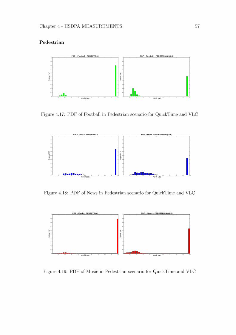
Chapter 4 - HSDPA MEASUREMENTS 57
Pedestrian
10 20 30 40 50 60 70 80 90 1000
0.1
0.2
0.3
0.4
0.5
0.6
0.7
0.8
0.9
1PDF − Football − PEDESTRIAN
PSNR [dB]
Empi
rical
PD
F
10 20 30 40 50 60 70 80 90 1000
0.1
0.2
0.3
0.4
0.5
0.6
0.7
0.8
0.9
1PDF − Football − PEDESTRIAN (VLC)
PSNR [dB]
Empi
rical
PD
F
Figure 4.17: PDF of Football in Pedestrian scenario for QuickTime and VLC
10 20 30 40 50 60 70 80 90 1000
0.1
0.2
0.3
0.4
0.5
0.6
0.7
0.8
0.9
1PDF − News − PEDESTRIAN
PSNR [dB]
Empi
rical
PD
F
10 20 30 40 50 60 70 80 90 1000
0.1
0.2
0.3
0.4
0.5
0.6
0.7
0.8
0.9
1PDF − News − PEDESTRIAN (VLC)
PSNR [dB]
Empi
rical
PD
F
Figure 4.18: PDF of News in Pedestrian scenario for QuickTime and VLC
10 20 30 40 50 60 70 80 90 1000
0.1
0.2
0.3
0.4
0.5
0.6
0.7
0.8
0.9
1PDF − Music − PEDESTRIAN
PSNR [dB]
Empi
rical
PD
F
10 20 30 40 50 60 70 80 90 1000
0.1
0.2
0.3
0.4
0.5
0.6
0.7
0.8
0.9
1PDF − Music − PEDESTRIAN (VLC)
PSNR [dB]
Empi
rical
PD
F
Figure 4.19: PDF of Music in Pedestrian scenario for QuickTime and VLC
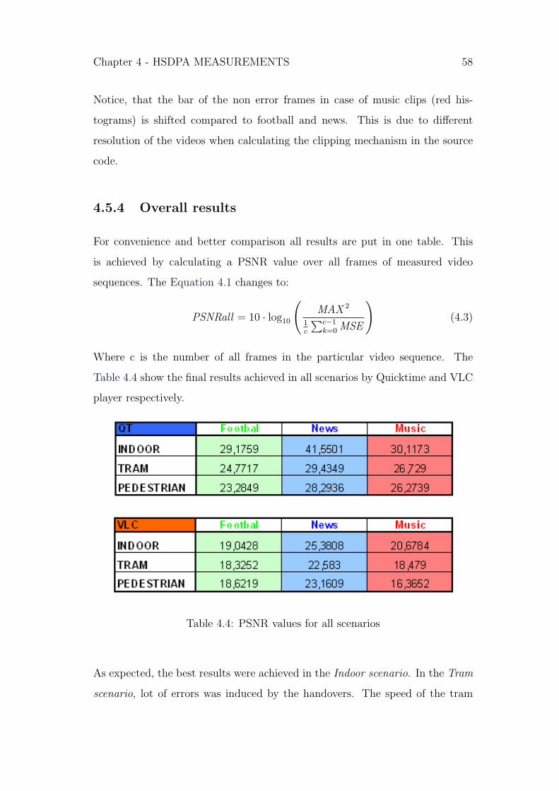
Chapter 4 - HSDPA MEASUREMENTS 58
Notice, that the bar of the non error frames in case of music clips (red his-
tograms) is shifted compared to football and news. This is due to different
resolution of the videos when calculating the clipping mechanism in the source
code.
4.5.4 Overall results
For convenience and better comparison all results are put in one table. This
is achieved by calculating a PSNR value over all frames of measured video
sequences. The Equation 4.1 changes to:
PSNRall = 10 · log10
(MAX 2
1c
∑c−1k=0 MSE
)(4.3)
Where c is the number of all frames in the particular video sequence. The
Table 4.4 show the final results achieved in all scenarios by Quicktime and VLC
player respectively.
Table 4.4: PSNR values for all scenarios
As expected, the best results were achieved in the Indoor scenario. In the Tram
scenario, lot of errors was induced by the handovers. The speed of the tram

Chapter 4 - HSDPA MEASUREMENTS 59
was not very high with lot of stops and thus one could see only small artifacts
on the video. These errors are visible on the corresponding histograms or on
the overall PSNR value which is in general lower than the indoor value. In the
Pedestrian scenario, the majority of errors were induced by the strong fading
and high data traffic. Therefore the results are in most cases even worse than
it was in the Tram scenario.
Further more, one can see the different performance between the content types.
News is showing best results. This is due to many similar frames in the news
video sequences. The scenes are not changing as fast as it is in case of Music
clip. Football is in most cases performing even worse than music. The reason
for this are the fast movements of the scenes in football.
Finally, the results confirm the assumption that QuickTime player would provide
better results than VLC.

Chapter 5
DVB-H MEASUREMENTS
For measuring DVB-H a different approach was used, which was somehow simi-
lar to HSDPA measurements, but still having some differences. The biggest one
was that unlike in HSDPA case, we were not able to use our own server for video
streaming. Therefore, no specific video content type could be chosen. One had
to deal with videos actually broadcasted by the content providers. The only
possibility to measure desired video type (e.g. football, news, or music clip)
was, to wait until it will be transmitted by any of the providers.
However this fact brought another consequence. Since we had no access to the
content providers, we were not able to get the original (reference) videos which
were broadcasted. Therefore it was impossible to measure the PSNR between
the captured video in particular scenario and the original video.
For these reasons another approach had to be chosen. The question was how to
get the original (reference) video for the measurements. For the solving of this
problem, three possibilities were proposed:
1. Getting the reference video by capturing it from digital cable TV.
2. Getting the reference video by capturing DVB-H close to the transmitter
(antenna).
3. Getting the reference video by capturing it form DVB-T
60

Chapter 5 - DVB-H MEASUREMENTS 61
The first approach was not chosen, because we couldn’t find needful equipment
(TV card and cable television).
The second approach was more considerable. The problem was that we had no
guarantee of error free transmission even being close to the antenna. Further-
more, since at the time there is only one antenna, broadcasting DVB-H services
in Vienna (trial service), there would be almost no difference between the refer-
ence video and measurements in indoor, or outdoor scenario. The only scenario
which could provide interesting results would be a moving scenario. In addition
to these reasons, comparing two DVB-H videos would not tell us anything about
the quality of DVB-H services.
After considering all pros and cons, the third approach was chosen. The moti-
vation was, that even though we are not able to measure the objective quality
of DVB-H video services, we can compare it to a similar, already worldwide
launched, DVB-T service. We found this solution very interesting and therefore
we decided for this approach. However, we were aware of many of the difficul-
ties, which we would face by choosing this approach. All of them are described
in section 5.5.
The following sections describe all information, about the DVB-H measure-
ments.
5.1 Scenarios
DVB-H technology is in Vienna, during the time of working on this thesis, only
in trial. There is only one antenna broadcasting the DVB-H services. Choosing
the test scenarios had to take in account this fact and hence the measurements
had to be provided close to the antenna.
As in the HSDPA case, also here was the effort to measure in the most promising
scenarios - Indoor, Pedestrian (outdoor) and Tram. Certainly, the location of
these scenarios is different than in the HSDPA case.

Chapter 5 - DVB-H MEASUREMENTS 62
The DVB - H antenna is on the Arsenal street, close to the railway station
Sudbahnhof and it is shown on the Figure 5.1 with black color. Indoor mea-
surements were provided inside the railway station building (green ”I”) For the
Pedestrian scenario the park Schweizer Garten was chosen (blue ”P”). Moving
scenario was measured in the tram number 18, which route is shown with red
color.
Figure 5.1: Locations of the DVB-H scenarios
5.2 Video Content
As already described in the introduction to this chapter, we were not able to
choose the video content type. Therefore, more or less randomly (explanation
follows in section 5.4) chosen video sequences were recorded.

Chapter 5 - DVB-H MEASUREMENTS 63
5.3 Tools
Many of the tools, which were needed in the HSDPA part, were used again.
Video sequences had to be played (using VLC player), recorded (Camtasia
Studio) and processed (VirtualDub and Matlab).
There are not many DVB - H receivers on the market which enable processing
on a computer (laptop). However as explained in chapter 3, DVB-H is only an
extension of DVB-T and therefore for purpose of this work a DVB-T receiver
was used. It was used in conjunction with special software, dvbSAM version 2
[Decontis], enabling DVB-H reception and processing. It is software for analyz-
ing, monitoring and testing of DVB-H transmissions. However, exploitation of
all its features was outside the scope of this thesis.
5.4 Methodology
In this section, there is an exact description of how the measurements were
provided.
5.4.1 Enabling DVB-H services on DVB-T receiver
The first task was to enable the reception of DVB-H services on a DVB-T
receiver. For this reason a comprehensive research was done, for looking a
suitable solution. As already mentioned, software dvbSAM was found to provide
this functionality.
5.4.2 Receiving and recording
Receiving DVB-T and DVB-H services on one receiver at the same time is
not possible. But there was a need to get two exactly same videos with these
technologies, DVB-T as a reference and DVB-H as the measured one. Instead

Chapter 5 - DVB-H MEASUREMENTS 64
of buying new DVB-T receiver, we decided to record and measure only those
videos (TV programs), which are being repeated on the next day. Using this
method, reference video was recorded using DVB-T at the evening and the
corresponding repetition was recorded using DVB-H on next day’s morning in
particular scenario.
Both, reference and measured videos, were recorded using the original software
for DVB-T receiver and the already mentioned dvbSAM for DVB-H. This pro-
cedure was different, but easier, as it was in the HSDPA case, where the received
videos were directly captured by Camtasia Studio.
5.4.3 Capturing
Although we had our desired video recorded, we were only able to run them by
using the particular application at which they were recorded. For example in
the DVB-H case, videos were saved in a transport stream container (.ts) and
even though this is a common container type, DVB-H videos were not detected
and read by any other application. Therefore we were not able to do anything
with recorded videos, because for doing the processing and calculations, videos
need to be in RAW format and AVI container.
The only solution we saw, was the capturing in Camtasia as it was done in the
HSDPA case. But unlike as in the HSDPA measurements, the videos here were
already recorded, so we had the possibility to do the capturing at any time.
5.4.4 Video processing and calculations
The processing and calculations where provided in the exactly same manner as
it was in HSDPA case, using the same calculations of the Equation 4.1 was used.
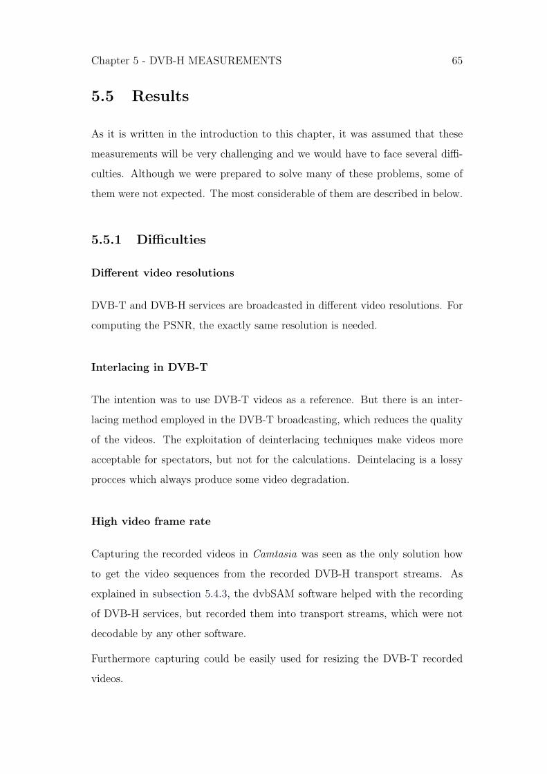
Chapter 5 - DVB-H MEASUREMENTS 65
5.5 Results
As it is written in the introduction to this chapter, it was assumed that these
measurements will be very challenging and we would have to face several diffi-
culties. Although we were prepared to solve many of these problems, some of
them were not expected. The most considerable of them are described in below.
5.5.1 Difficulties
Different video resolutions
DVB-T and DVB-H services are broadcasted in different video resolutions. For
computing the PSNR, the exactly same resolution is needed.
Interlacing in DVB-T
The intention was to use DVB-T videos as a reference. But there is an inter-
lacing method employed in the DVB-T broadcasting, which reduces the quality
of the videos. The exploitation of deinterlacing techniques make videos more
acceptable for spectators, but not for the calculations. Deintelacing is a lossy
procces which always produce some video degradation.
High video frame rate
Capturing the recorded videos in Camtasia was seen as the only solution how
to get the video sequences from the recorded DVB-H transport streams. As
explained in subsection 5.4.3, the dvbSAM software helped with the recording
of DVB-H services, but recorded them into transport streams, which were not
decodable by any other software.
Furthermore capturing could be easily used for resizing the DVB-T recorded
videos.

Chapter 5 - DVB-H MEASUREMENTS 66
However, this method is only reasonable if the capturing is provided by a dou-
bled frame rate than the actual video. Since the DVB-T and DVB-H services
are broadcasted by a frame rate of 25 FPS a reasonable capturing frame rate
would be 50 FPS. Even though the video resolution was only 320x240 pixels,
capturing at such high frame rate would need much more powerful computers.
On computers used for this work, the acceptable frame rate for capturing was
just 25 FPS.
The capturing of videos at their own frame rate caused the captures to be
inaccurate, with some frames doubled and some frames dropped.
Different coding format
Another difference between DVB-T and DVB-H broadcasting is in the video
coding format. They are using MPEG-2 and H.264 respectively. Furthermore
they are coded to different data rates, resulting in the better quality of DVB-
T. This implies that calculating the PSNR between these videos would never
provide any non-error frames as it was in the HSDPA case. An obvious example
is shown on the Figure 5.2.
Figure 5.2: The difference between coding formats of DVB-T and DVB-H
Chapter 5 - DVB-H MEASUREMENTS 67
Different color shade
Even worse problem than the previous one, was a little, but still visible color
difference of the videos. Having the measured and the reference video abreast,
one could see the different shade. It is the matter of the different coding format,
but also the matter of the player used for the recording. An example is shown on
the Figure 5.3. This problem implies that not only the frames of the captured
and measured video can not be the same, but also that each pixels are different
Figure 5.3: The color shade of DVB-T and DVB-H video
5.5.2 PSNR analyses
Although many of the above described difficulties could be solved, the quality
of the reference DVB-T video was not reliable enough. Futhermore many of the
solutions raised more and more problems. However, after partially overcoming
the main problematic issues, we could finally compute the PSNR between the
reference and the measured videos. There is a graph on the Figure 5.4 showing
the PSNR between the first 1000 frames of the pedestrian scenario. It clearly
shows the degradation of the DVB-H video over DVB-T, but also the absence
of any non-error frames.

Chapter 5 - DVB-H MEASUREMENTS 68
100 200 300 400 500 600 700 800 900 10000
10
20
30
40
50
60
70
80
90
100DVB−H Outdoor − PSNR
Frames
PS
NR
[dB
]
Figure 5.4: PSNR between the first 1000 frames of the pedestrian scenario
Although, the results show the quality difference between DVB-T and DVB-H,
they hide many other errors, which cannot be identified (e.g. different coding,
interlacing errors, capturing errors, etc.). The most important, it is not clear
which errors are induced by different scenarios. For these reasons they are
considered to be insufficient for the initial aim of this thesis and therefore are
not presented at this place.

Chapter 6
CONCLUSIONS
The aim of this work was to evaluate the performance of the state-of-the-art
mobile video delivery technologies. For this purpose, DVB-H and HSDPA were
investigated. This work should prove, whether these technologies are suitable,
or mature enough, to provide ”high quality” video services. ”High quality”
video was defined in chapter 1 as any video with data rate higher than 200
kbps. All information about the provided measurements (where, what and how
was measured) is in detail described in previous chapter 4 and chapter 5. These
chapters also include the results of this work.
Altogether, the most important conclusion of this thesis is that the investigated
technologies are already suitable for providing ”high quality” video services.
This was proved by computing the PSNR between some original and measured
videos in different scenarios. The resulting PSNR values might look a bit low,
comparing it to usual PSNR values for video compression (which is around 30
dB). But there is an important difference between video compression and PSNR
measurements provided in this thesis. When comparing a compressed video to
its original, there is an almost constant, but small degradation of the video. In
the measurements for this thesis, there is no constant degradation. The mea-
sured video has the same coding format and data rate as its original. Therefore
the measured video in many parts equal to the original, but in some parts, arti-
69
Chapter 6 - CONCLUSIONS 70
facts induced by the transmission arise. When computing a PSNR of an artifact
frame, the value is very low. Having a video with some corrupted frames pro-
vides low PSNR. Therefore the PSNR values for the provided measurements are
lower in general.
The measurements of HSDPA technology provide acceptable and sufficient PSNR
results, but also some other very interesting conclusions. Unfortunately, because
of the absence of the original video sequences, there was no expected success
achieved within the DVB-H measurements.
Some other conclusions of this work are concerning the video quality dependence
on several factors, but mostly on:
• Video content
• Scenario
• Software tools
The measurements clearly show the expected better quality of ”news” video
over the others. This is due to few and slow changes in this video content.
Some changes between the performances in different scenarios were also ex-
pected. This work proves that a stable indoor scenario performs better than
the moving scenarios.
However, the most interesting result was about the video players. In chapter 4
was shown and proved that the video quality depends also on the software tools.
In this thesis two players were investigated - QuickTime and VLC. It was proved
that QuickTime player cooperates with Darwin Streaming Server (DSS) and
thus provides better results than the VLC player. This knowledge emphasizes
the importance of choosing, or adjusting, the cooperation between streaming
server and client’s application, when designing a video service for customer.
Good cooperation, as at is in case of QuickTime and DSS, can improve the
quality significantly.
Chapter 6 - CONCLUSIONS 71
Although the measurements of HSDPA provided satisfactory results, there is
still some space for futher improvements. These could be achieved by an au-
tomatic measurement environment, which would allow an easier performance
evaluation of longer video sequences. This would yield better statistics.
The DVB-H measurements were more complicated due to the fact of not having
access to the content provider and thus not having the original video sequences.
Therefore an alternative solution was searched. As described in introduction to
chapter 5, comparing DVB-T and DVB-H was seen as the best possible answer.
Nevertheless, it led only to not satisfactory results. These were therefore only
shortly shown in this thesis, but not all of them were published. To evaluate
the performance of DVB-H video delivery, we propose to have the original video
sequences. This can be achieved by cooperating with the content provider.
Another approach is to use a DVB-H simulator for analyzing this service. A
project using this approach was just opened at our institute.

Appendix
function PSNR(aviName_orig,aviName_copy)
info_orig=aviinfo(aviName_orig);
info_copy=aviinfo(aviName_copy); % read information about avi files
do=info_copy.NumFrames % number of frames
Wid=info_copy.Width;
Hei=info_copy.Height;
PSNR_Clipp=((255^2)*Wid*Hei); %Clipping value
limit=floor(do/100)
rest=mod(do,100)
if(rest>0);
limit=limit+1;
end
for k=1:limit
if(rest>0)&&(k==limit)
framesA=k*100-99;
framesB=k*100-100+rest;
72
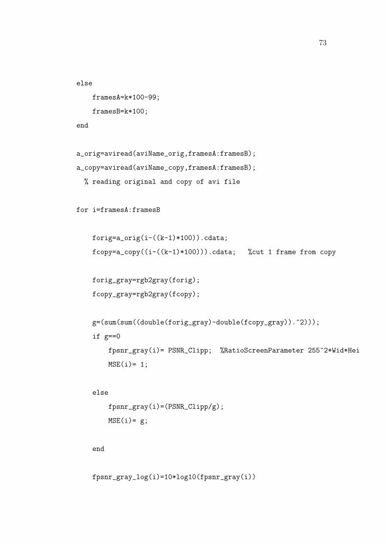
73
else
framesA=k*100-99;
framesB=k*100;
end
a_orig=aviread(aviName_orig,framesA:framesB);
a_copy=aviread(aviName_copy,framesA:framesB);
% reading original and copy of avi file
for i=framesA:framesB
forig=a_orig(i-((k-1)*100)).cdata;
fcopy=a_copy((i-((k-1)*100))).cdata; %cut 1 frame from copy
forig_gray=rgb2gray(forig);
fcopy_gray=rgb2gray(fcopy);
g=(sum(sum((double(forig_gray)-double(fcopy_gray)).^2)));
if g==0
fpsnr_gray(i)= PSNR_Clipp; %RatioScreenParameter 255^2*Wid*Hei
MSE(i)= 1;
else
fpsnr_gray(i)=(PSNR_Clipp/g);
MSE(i)= g;
end
fpsnr_gray_log(i)=10*log10(fpsnr_gray(i))
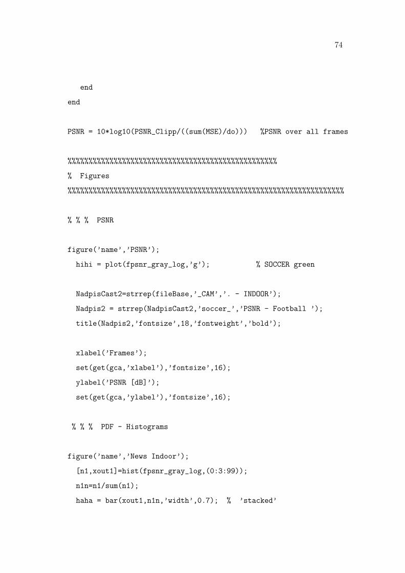
74
end
end
PSNR = 10*log10(PSNR_Clipp/((sum(MSE)/do))) %PSNR over all frames
%%%%%%%%%%%%%%%%%%%%%%%%%%%%%%%%%%%%%%%%%%%%%%%%%%
% Figures
%%%%%%%%%%%%%%%%%%%%%%%%%%%%%%%%%%%%%%%%%%%%%%%%%%%%%%%%%%%%%%%%%%
% % % PSNR
figure(’name’,’PSNR’);
hihi = plot(fpsnr_gray_log,’g’); % SOCCER green
NadpisCast2=strrep(fileBase,’_CAM’,’. - INDOOR’);
Nadpis2 = strrep(NadpisCast2,’soccer_’,’PSNR - Football ’);
title(Nadpis2,’fontsize’,18,’fontweight’,’bold’);
xlabel(’Frames’);
set(get(gca,’xlabel’),’fontsize’,16);
ylabel(’PSNR [dB]’);
set(get(gca,’ylabel’),’fontsize’,16);
% % % PDF - Histograms
figure(’name’,’News Indoor’);
[n1,xout1]=hist(fpsnr_gray_log,(0:3:99));
n1n=n1/sum(n1);
haha = bar(xout1,n1n,’width’,0.7); % ’stacked’
75
NadpisCast=strrep(fileBase,’_CAM’,’. - INDOOR’);
Nadpis = strrep(NadpisCast,’soccer_’,’PDF - Football ’);
axis([1 100 0 1]);
set(haha,’FaceColor’,’g’) %
set(haha,’linewidth’,1)
title(Nadpis,’fontsize’,18,’fontweight’,’bold’);
xlabel(’PSNR [dB]’);
set(get(gca,’xlabel’),’fontsize’,16);
ylabel(’Empirical PDF’);
set(get(gca,’ylabel’),’fontsize’,16);

Bibliography
[3GPP] Third Generation Partnership Project, URL, http://www.3gpp.org
[Alcat 06] Philippe Laine, Alistair Urie, Philip Kelley, Christophe Nussli, ”Un-
limited Mobile TV for the Mass Market”, Alcatel’s Strategy White Paper,
February 2006
[Am Evol 04] 3G Americas, ”The Evolution of UMTS - 3GPP Release 5 and
Beyond”, August 2004
[Am Rel 7] 3G Americas, ”Mobile Broadband: The Global Evolution of
UMTS/HSPA 3GPP Release 7 and Beyond”, July 2006
[AMC 3G] James Yang, Noel Tin, and Amir K. Khandani, ”Adaptive Modu-
lation and Coding in 3G Wireless Systems”, IEEE Vehicular Technology
Conference, Pages 544-548, Vol. 1, 2002
[Apple] Apple Inc., URL, http://www.apple.com
[Balaguer] Edith de Diego Balaguer, ”DVB-H Mobile Television”, Dept. of
Communication Technology, Aalborg University
[Bennett] Bruce Bennett, Pamela Hemmings,Christopher Holt, Booz Allen
Hamilton, McLean, ”Digital Video Broadcast - Handheld (DVB-H) - A
Mobile Last-Mile Tactical Broadcast Solution”, IEEE Military Communi-
cations Conference, Pages 141-147, Vol.1, October 2005
[Decontis] Decontis GmbH, URL, http://www.decontis.com
76

77
[DigiTAG 05] Digital Terrestrial Television Action Group, ”Television on a
handheld receiver - broadcasting with DVB-H”, DigiTAG, Version 1.2, 2005
[Dotlling] Martin Dotlling, Jurgen Michel, Bernhard Raaf, ”Hybrid ARQ and
Adaptive Modulation and Coding Schemes for High Speed Downlink Packet
Access”, IEEE Personal Indoor and Mobile Radio Communications, Pages
1073-1077, Vol.3, September 2002
[DSCH Design] Arnab Das, Farooq Khan, Ashwin Sampath and Hsuan-Jung
Su, ”Design and Performance of Downlink Shared Control Channel for
HSDPA”, IEEE Personal Indoor and Mobile Radio Communications, Pages
1088-1091, Vol.3, September 2002
[DVBServ] Global Mobile TV DVB-H, URL, http://www.dvb-
h.org/services.htm
[EN 300 468] ETSI, ”Digital Video Broadcasting (DVB); Specification for Ser-
vice Information (SI) in DVB systems”, EN 300 468 v1.5.1, January 2003
[EN 300 744] ETSI, ”Digital Video Broadcasting (DVB); Framing structure,
channel coding and modulation for digital terrestrial television”, EN 300
744 v1.5.1, June 2004
[EN 301 192] ETSI, ”Digital Video Broadcasting (DVB); DVB specification for
data broadcasting”, EN 301 192 v1.4.1, June 2006
[EN 302 304] ETSI, ”Digital Video Broadcasting (DVB); Transmission System
for Handheld Terminals (DVB-H)”, EN 302 304 v1.1.1, November 2004
[Etoh] Minoru Etoh, and Takeshi Yoshimura, ”Advances in Wireless Video De-
livery”, Proceedings of the IEEE, Pages 111-122, Vol. 93, No. 1, January
2005
[FactSheet 07] DVB Fact Sheet, ”Broadcasting to Handhelds”, in URL,
http://www.dvb-h.org, February 2007
78
[FactIP 07] DVB Fact Sheet, ”Internet Protocol Datacast”, in URL,
http://www.dvb-h.org, February 2007
[Faria 02] Gerard Faria, ”New Operative Modes for Digital Terrestrial TV”,
Teamcast, Singapore, June 2002
[Far Hen 06] Gerard Faria, Jukka A. Henriksson, Erik Stare, Pekke Talmola,
”DVB-H: Digital Broadcast Services to Handheld Devices”, Proceedings of
the IEEE, Pages 194-209, Vol. 94, No.1, January 2006
[Hakaste] Markus Hakaste, Eero Nikula and Shkumbin Hamiti, ”GSM/EDGE
Standards Evolution (up to Rel’4)”, John Wiley & Sons Ltd., ISBN: 0-470-
86694-2, 2003
[HARQ] Arnab Das, Farooq Khan, Ashwin Sampath and Hsuan-Jung Su, ”Per-
formance of Hybrid ARQ for High Speed Downlink Packet Access in
UMTS”, Bell Laboratories, Lucent Technologies, Holmdel, USA, 2001
[Henriksson 05] Jukka Henriksson,”DVB-H - standard, principles and services”,
Nokia Research Center, Helsinki, February 2005
[Hiltunen] Kimmo Hiltunen, Magnus Lundevall, Sverker Magnusson, ”Perfor-
mance of Link Admission Control in a WCDMA System with HS-DSCH
and Mixed Services”, IEEE Personal, Indoor and Mobile Radio Communi-
cations, Pages 1178-1182, Vol.2, September 2004
[Himmanen 06] Heidi Himmanen, Ali Hazmi, Jarkko Paavola, ”Comparison of
DVB-H Link Layer FEC Decoding Strategies in a Mobile Fading Chan-
nell”, IEEE Personal, Indoor and Mobile Radio Communications, Pages
1-5, September 2006
[IEEE Survey 06] Xiaodong Yang, Jani Vare, Thomas J. Owens, ”A Survey
of Handover Algorithms in DVB-H”, IEEE Communications Surveys &
Tutorials, Pages 16-29, Vol. 8, No. 4, 4th Quarter 2006

79
[Kangas 06] Mauri Kangas, ”DVB and DVB-H Systems”, Helsinki University
of Technology, Post-Graduate Course in Radio Communication, January
2006
[Knoche 05] Hendrik Knoche, John D. McCarthy, ”Design Requirements for
Mobile TV”, MobileHCI’05, University College London, Salzburg, Austria,
September 2005
[Kornfeld 05] Michael Kornfeld, Ulrich Reimers, ”DVB-H - The emerging stan-
dard for mobile data communication”, IEEE Consumer Electronics, Pages
193-198, September 2004
[Kornfeld May 07] Michael Kornfeld, Gunther May, ”DVB-H and IP Datacast
- Broadcast to Handheld Devices”, IEEE Transaction on Broadcasting,
Pages 161-170, Vol. 53, No. 1, March 2007
[Kornf Perf 06] Michael Kornfeld, ”DVB-H for Wireless Broadband Terminal
Access - A Performance Evaluation”, IEEE Consumer Electronics, Pages
413- 414, January 2006
[Lopez 06] A. Lopez, G. Fernandez, ”Efficient media delivery over mobile ter-
minals using DVB-H”, IEEE Consumer Electronics, Pages 1-6, 2006
[LGe] LG Electronics, URL, http://www.lge.com
[Lundevall] Magnus Lundevall, Birgitta Olin, Jonas Olsson, Niclas Wiberg, Ste-
fan Wanstedt, Jonas Eriksson and Frida Eng, ”Streaming Applications over
HSDPA in Mixed Service Scenarios”, IEEE Vehicular Technology Confer-
ence, Pages 841- 845, Vol. 2, September 2004
[May] Gunther May, ”IP Datacast over DVB-H”, Institute for Communications
Technology, Technische Universitat Braunschweig, Germany, 2004
[MathWorks] MathWorks, URL, http://www.mathworks.com
80
[MobKom] Mobilkom Austria, URL, http://www.mobilkomaustria.at
[MPE Sim 05] Teh Chee Hong, Wan Tat Chee, Rahmat Budiarto, ”Simulation
and Design of IP over DVB using Multi-Protocol Encapsulation and Ul-
tra Lightweight Encapsulation”, National Computer Science Postgraduate
Colloquium, University Sains Malaysia, June 2005
[Nadschl 06] Elmar Nadschlager, ”Technological and Economical Aspects of
Digital Video Broadcasting for Handheld”, Diploma thesis, Institut for
Broadband Communication, TU Wien, 2006
[Nok Inter] Nokia, ”DVB-H: Live broadcast MobileTV”, in URL,
http://www.nokia.com/mobiletv
[Nokia] Nokia, URL, http://www.nokia.com
[Nort paper] Nortel, ”HSDPA and beyond”, White paper, 2005
[Ofuji] Yoshiaki Ofuji, Akihito Morimoto, Sasayuki Abeta and Mamuru
Sawashi, ”Comparison of Packet Scheduling Algorithms Focusing on User
Throughput in HSDPA”, IEEE Personal, Indoor and Mobile Radio Com-
munications, Pages 1462-1466, Vol.3, September 2002
[Ollikain] V. Ollikainen, C. Peng, ”Integration of DVB-T into DVB-H Trans-
mission Systems”, VTT Research Centre of Finland, 2006
[Park Eng] Stefan Parkvall, Eva Englund, Peter Malm, Tomas Hedberg, Mag-
nus Persson and Janne Peisa, ”WCDMA evolved-High-speed packet-data
services”, Ericsson Review No. 2, Sweden, 2003
[Parkvall] Stefan Parkvall, Erik Dahlman, Pal Frenger, Per Beming, Magnus
Persson, ”The Evolution of WCDMA Towards Higher Speed Downlink
Packet Data Access”, Ericsson Research, Stockholm, Sweden, 2001
[Qualcomm] , Qualcomm, ”HSDPA for Improved Downlink Data Transfer”,
Qualcomm CDMA Technology White Paper, October 2004

81
[Rhode] Rhode & Schwarz, ”DVB-H Solutions”, in URL, http://www.rohde-
schwarz.com
[Sams] Samsung, ”DVB-H Digital Video Broadcasting for Handhelds”, White
Paper, Germany, in URL, http://mobiletv.samsungmobile.com
[Siem] Siemens, URL, http://www.siemens.com
[Summary 99] ETSI Mobile Competence Centre, ”Overview of 3GPP Release
99 Summary of all Release 99 Features”, Version 05/03/04
[Summary 04] ETSI Mobile Competence Centre, ”Overview of 3GPP Release
4 Summary of all Release 4 Features”, v.1.1.0 (draft), 2004
[Summary 05] ETSI Mobile Competence Centre, ”Overview of 3GPP Release
5 Summary of all Release 5 Features”, Version 9th September 2003
[Summary 06] ETSI Mobile Competence Centre, ”Overview of 3GPP Release
99 Summary of all Release 99 Features”, Version TSG #33, 2006
[TechSmith] TechSmith, URL, http://www.techsmith.com
[Torshizi 06] Glenn Torshizi, Estefanos Woldemariam, ”Mobile Tv on the move
with Digital Video Broadcast-Handheld standard”, Bechtel Corporation,
June 2006
[TR 102 377] ETSI, ”Digital Video Broadcasting (DVB); DVB-H Implementa-
tion Guidelines”, TR 102 377 v1.2.1, November 2005
[Troels] Troels E. Kolding, ”Link and System Performance Aspects of Propor-
tional Fair Scheduling in WCDMA/HSDPA”, IEEE Vehicular Technology
Conference, Pages 1717-1722, Vol.3, October 2003
[TS 25.308] 3GPP; Technical Specification Group Radio Access Network, ”High
Speed Downlink Packet Access (HSDPA); Overall description;”, Stage 2
(Release 6), V6.4.0, March 2007

82
[TVhist] Television History, URL, http://www.tvhistory.tv
[UMTS Forum] UMTS Forum, URL, http://www.umts-forum.org
[VideoLAN] VideoLAN project, URL, http://www.videolan.org
[Yang Song 04] X.D. Yang, Y.H. Song, T.J. Owens, J. Cosmas, T. Itagaki, ”Per-
formance analysis of time slicing in DVB-H”, Mobile Future, 2004 and the
Symposium on Trends in Communications, Pages 183-186, October 2004
[Wang] Yubing Wang, ”Survey of Objective Video Quality Measurements”,
EMC Corporation Hopkinton, USA
[Winkler] , Stefan Stefan, Digital Video Quality: Vision Models and Metrics,
”Video Quality”, Page 5, John Wiley & Sons Ltd., 2005
[Wireless] Andreas F. Molisch, Wireless Communications, ”WCDMA/UMTS”,
Page 513, John Wiley & Sons Ltd., The Atrium, Southern Gate, Chichester,
West Sussex, England, 2005
[Wireshark] Wireshark, URL, http://www.wireshark.org


